WO2022130634A1 - 空気調和システム - Google Patents
空気調和システム Download PDFInfo
- Publication number
- WO2022130634A1 WO2022130634A1 PCT/JP2020/047515 JP2020047515W WO2022130634A1 WO 2022130634 A1 WO2022130634 A1 WO 2022130634A1 JP 2020047515 W JP2020047515 W JP 2020047515W WO 2022130634 A1 WO2022130634 A1 WO 2022130634A1
- Authority
- WO
- WIPO (PCT)
- Prior art keywords
- air conditioning
- indoor
- humidity
- air
- heat load
- Prior art date
Links
- 238000004378 air conditioning Methods 0.000 title claims abstract description 263
- 238000009423 ventilation Methods 0.000 claims description 58
- 239000003507 refrigerant Substances 0.000 claims description 10
- 238000007664 blowing Methods 0.000 claims description 5
- 238000009833 condensation Methods 0.000 abstract description 9
- 230000005494 condensation Effects 0.000 abstract description 9
- 238000001514 detection method Methods 0.000 description 21
- 238000000034 method Methods 0.000 description 21
- 238000010586 diagram Methods 0.000 description 20
- 238000013528 artificial neural network Methods 0.000 description 9
- 230000005540 biological transmission Effects 0.000 description 5
- 238000001816 cooling Methods 0.000 description 5
- 230000002265 prevention Effects 0.000 description 5
- 238000012986 modification Methods 0.000 description 4
- 230000004048 modification Effects 0.000 description 4
- 230000001276 controlling effect Effects 0.000 description 3
- 210000002569 neuron Anatomy 0.000 description 3
- 230000007613 environmental effect Effects 0.000 description 2
- 238000001704 evaporation Methods 0.000 description 2
- 230000008020 evaporation Effects 0.000 description 2
- 238000010438 heat treatment Methods 0.000 description 2
- 230000002787 reinforcement Effects 0.000 description 2
- 238000013459 approach Methods 0.000 description 1
- 238000013135 deep learning Methods 0.000 description 1
- 238000000605 extraction Methods 0.000 description 1
- 230000006870 function Effects 0.000 description 1
- 230000002068 genetic effect Effects 0.000 description 1
- 238000010801 machine learning Methods 0.000 description 1
- 238000003062 neural network model Methods 0.000 description 1
- 238000005057 refrigeration Methods 0.000 description 1
- 230000001105 regulatory effect Effects 0.000 description 1
- 230000009385 viral infection Effects 0.000 description 1
Images


Classifications
-
- F—MECHANICAL ENGINEERING; LIGHTING; HEATING; WEAPONS; BLASTING
- F24—HEATING; RANGES; VENTILATING
- F24F—AIR-CONDITIONING; AIR-HUMIDIFICATION; VENTILATION; USE OF AIR CURRENTS FOR SCREENING
- F24F11/00—Control or safety arrangements
- F24F11/30—Control or safety arrangements for purposes related to the operation of the system, e.g. for safety or monitoring
- F24F11/46—Improving electric energy efficiency or saving
-
- F—MECHANICAL ENGINEERING; LIGHTING; HEATING; WEAPONS; BLASTING
- F24—HEATING; RANGES; VENTILATING
- F24F—AIR-CONDITIONING; AIR-HUMIDIFICATION; VENTILATION; USE OF AIR CURRENTS FOR SCREENING
- F24F11/00—Control or safety arrangements
- F24F11/62—Control or safety arrangements characterised by the type of control or by internal processing, e.g. using fuzzy logic, adaptive control or estimation of values
- F24F11/63—Electronic processing
- F24F11/64—Electronic processing using pre-stored data
-
- F—MECHANICAL ENGINEERING; LIGHTING; HEATING; WEAPONS; BLASTING
- F24—HEATING; RANGES; VENTILATING
- F24F—AIR-CONDITIONING; AIR-HUMIDIFICATION; VENTILATION; USE OF AIR CURRENTS FOR SCREENING
- F24F2110/00—Control inputs relating to air properties
- F24F2110/10—Temperature
-
- F—MECHANICAL ENGINEERING; LIGHTING; HEATING; WEAPONS; BLASTING
- F24—HEATING; RANGES; VENTILATING
- F24F—AIR-CONDITIONING; AIR-HUMIDIFICATION; VENTILATION; USE OF AIR CURRENTS FOR SCREENING
- F24F2110/00—Control inputs relating to air properties
- F24F2110/20—Humidity
Definitions
- This disclosure relates to an air conditioning system.
- the ventilation control device of Patent Document 1 Japanese Unexamined Patent Publication No. 7-120022
- the ventilation control device of Patent Document 1 has a ventilation fan for ventilating the room, a plurality of sensors for detecting the environmental state in the room, and input values of the sensors to the input layer.
- a neural network that is trained by allocating ventilation to the output layer, a judgment unit that selects ventilation from the output value of the output layer of the neural network, and a drive that controls the operation of the ventilation fan based on the selection result of the judgment unit. It is equipped with a control unit.
- the ventilation control device described in Patent Document 1 can optimize the ventilation volume, but is an air conditioning device corresponding to natural ventilation randomly generated by a person opening an opening of an air conditioning management space such as a window. Cannot be controlled.
- the object of the present disclosure is to provide an air conditioning system capable of controlling the air conditioning equipment according to natural ventilation.
- the air conditioning outlet when notified that the air conditioning equipment and the opening of the air conditioning control space are open, the air conditioning outlet does not condense multiple indoor target temperatures and indoor target humidity.
- the candidate having the minimum power consumption is selected, and the control device for controlling the air conditioning equipment is provided based on the selected candidate.
- the candidate with the lowest power consumption is selected from the candidates for the combination of the indoor target temperature and the indoor target humidity in which the air conditioning outlet does not condense, so that the air conditioning according to the natural ventilation is selected.
- Equipment can be controlled.
- FIG. It is a figure which shows the structure of the air conditioning system 100 of Embodiment 1.
- FIG. It is a figure which shows the structure of the control panel 500 of Embodiment 1.
- FIG. It is a schematic diagram of the refrigerant circuit of the air conditioning system 100.
- It is a figure which shows the schematic structure of the ventilation apparatus 13.
- It is a figure which shows the data about the heat load amount in the air-conditioning management space in Embodiment 1.
- FIG. It is a figure which shows the structure of the learning apparatus 101.
- It is a flowchart which shows the learning procedure of a learning apparatus 101.
- FIG. It is a figure which shows the 1st example of the candidate of the combination of the target temperature and the target humidity so that the air conditioning outlet does not condense dew. It is a figure which shows the 2nd example of the candidate of the combination of the target temperature and the target humidity so that the air conditioning outlet does not condense dew. It is a figure which shows the 3rd example of the candidate of the combination of the target temperature and the target humidity so that the air conditioning outlet does not condense dew.
- FIG. It is a figure which shows the structure of the air conditioning system 100 of Embodiment 2. It is a figure which shows the data about the heat load amount in the air-conditioning management space in Embodiment 2.
- FIG. It is a flowchart which shows the procedure of the dew condensation prevention control of Embodiment 2. It is a figure which shows the structure of the air conditioning system 100 of Embodiment 3. It is a figure which shows the structure of the control panel 500 of Embodiment 3. It is a figure which shows the hardware composition of the learning apparatus 101, the inference apparatus 201, or the control apparatus 600.
- FIG. 1 is a diagram showing the configuration of the air conditioning system 100 of the first embodiment.
- the air conditioning system 100 includes a control panel 500 and an air conditioning facility 200.
- the air conditioner 200 includes an air conditioner 1 that operates as an internal air conditioner and a ventilation device 13 that operates as an external air conditioner.
- the air conditioning device 1 mainly handles the sensible heat load in the room 901, which is an air conditioning management space.
- the ventilation device 13 ventilates the room 901, which is an air conditioning management space, and mainly processes the latent heat load in the room 901.
- FIG. 2 is a diagram showing the configuration of the control panel 500 of the first embodiment.
- the control panel 500 includes a target temperature / humidity input unit 44, a control device 600, a learning device 101, a learned model storage device 301, and an inference device 201.
- the control device 600 includes an air conditioning control unit 601 and a display device 701.
- the air conditioning outlet does not condense dew.
- the candidate with the lowest power is selected, and the air conditioning equipment 200 is controlled based on the selected candidate.
- the air-conditioned harmony management space is, for example, an indoor space.
- the opening is a window, a door, a shutter, or the like.
- the open / closed state is an open state or a closed state.
- the control device 600 When the opening of the air conditioning control space is open, the control device 600 does not condense dew on the air conditioning outlet. If there is no candidate for a combination of a plurality of indoor target temperatures and indoor target humidity, the air conditioning equipment 200 The circulation of the refrigerant is stopped, and the air conditioning equipment 200 is operated by blowing air.
- the control device 600 When the control device 600 receives a notification that the opening of the air conditioning management space is open and then a notification that the opening of the air conditioning management space is closed, the control device 600 manages the air conditioning.
- the air conditioning equipment 200 is controlled based on the indoor target temperature and the indoor target humidity set by the user through the target temperature / humidity input unit 44 before receiving the notification that the opening of the space is in the open state.
- the air conditioner 1 includes a plurality of indoor units 11 and an outdoor unit 12.
- the outdoor unit 12 is installed outdoors.
- the indoor unit 11 is installed in the room 901.
- Each of the outdoor unit 12 and each indoor unit 11 is connected to the control device 600 by the transmission line 903.
- the ventilation device 13 is connected to the control device 600 by the transmission line 903.
- FIG. 3 is a schematic diagram of the refrigerant circuit of the air conditioning system 100.
- the air conditioner 1 includes a compressor 2, a four-way valve 3, an outdoor heat exchanger 4, an expansion valve 5, and an indoor heat exchanger 6. These are sequentially connected by pipes to form a refrigeration cycle configured to circulate the refrigerant.
- the air conditioner 1 further includes an outdoor heat exchanger blower 7 and an indoor heat exchanger blower 8.
- a compressor 2 a four-way valve 3, an outdoor heat exchanger 4, and a blower for an outdoor heat exchanger 7 are installed in the outdoor unit 12.
- the outdoor unit 12 is provided with an evaporation temperature detecting device 31.
- Each indoor unit 11 is provided with a suction temperature / humidity detection device 32 that detects the temperature / humidity of the suction air of the indoor unit 11.
- the ventilation device 13 includes an expansion valve 5a mounted on the ventilation device and a cooler 9 for the ventilation device.
- the ventilation device-mounted expansion valve 5a and the ventilation device cooler 9 connected in series to each other are connected in parallel to the expansion valve 5 and the indoor heat exchanger 6.
- the ventilator 13 is provided with an air supply blower 10 for allowing air to pass through the ventilator cooler 9.
- the air conditioner 1 is configured so that the flow direction of the refrigerant discharged from the compressor 2 can be switched by the four-way valve 3 to switch between cooling operation and heating operation.
- the indoor heat exchanger 6 and the ventilator cooler 9 serve as an evaporator
- the outdoor heat exchanger 4 serves as a condenser
- the cooling operation is performed.
- the indoor heat exchanger 6 becomes a condenser
- the outdoor heat exchanger 4 becomes an evaporator
- FIG. 3 shows the flow of the refrigerant during the cooling operation.
- FIG. 4 is a diagram showing a schematic configuration of the ventilation device 13.
- the ventilation device 13 includes a ventilation device cooler 9, a total heat exchanger 22, an air supply blower 10, and an exhaust blower 21 in the main body casing 13a.
- the air supply air passage A and the exhaust air passage B are formed independently of each other.
- the air supply air passage A takes in the outdoor air OA by the air supply blower 10 and passes it through the total heat exchanger 22 and the ventilation device cooler 9, and supplies it to the indoor 901 as the regulated air SA.
- the exhaust ventilation passage B takes in the indoor air RA by the exhaust blower 21 and passes it through the total heat exchanger 22, and exhausts it to the outside as an exhaust EA.
- the air that flows into the ventilator cooler 9 after passing through the total heat exchanger 22 in the air supply air passage A is referred to as a cooler inflow air IA.
- the ventilation device 13 further includes a cooler inflow temperature / humidity detection device 23 that detects the temperature and humidity of the cooler inflow air IA, a CO2 concentration detection device 24 that detects the CO2 concentration of the indoor air RA, and a ventilation air volume detection device 25. To prepare for. The detected values of these detection devices 23 to 25 are output to the control device 600 via the transmission line 903.
- the total heat exchanger 22 has, for example, a structure in which ventilation passages orthogonal to each other are alternately laminated.
- the ventilator cooler 9 is composed of an evaporator of a refrigerating cycle, and cools the air passing through itself to a dew point temperature or lower to dehumidify it.
- the ventilator 13 handles the latent heat load in the room 901 by the total heat exchanger 22 and the ventilator cooler 9.
- the air supply blower 10 and the exhaust blower 21 control the amount of air flowing in the ventilation device 13 by controlling the rotation speed.
- the ventilation device 13 configured in this way, ventilation is performed with the required ventilation volume (air volume VA) for maintaining a good environment (air quality, for example, CO2 concentration) in the room 901 (for example, keeping the CO2 concentration at 1000 ppm or less).
- the control device 600 controls the rotation speeds of the air supply blower 10 and the exhaust blower 21.
- the ventilation device 13 passes the outdoor air OA through the total heat exchanger 22 of the air supply air passage A and the cooler 9 for the ventilation device to dehumidify and supply the room 901, while the indoor air RA is supplied to the indoor air passage.
- the latent heat load in the room 901 is processed by passing it through B and exhausting it to the outside of the room.
- the air conditioning system 100 further includes an indoor temperature sensor 501, an indoor humidity sensor 502, an outdoor temperature sensor 503, and an outdoor humidity sensor 504.
- the indoor temperature sensor 501 and the indoor humidity sensor 502 are arranged indoors, and the outdoor temperature sensor 503 and the outdoor humidity sensor 504 are arranged outdoors.
- the control device 600 is connected to each of the indoor temperature sensor 501, the indoor humidity sensor 502, the outdoor temperature sensor 503, and the outdoor humidity sensor 504 by a transmission line 903.
- the indoor temperature sensor 501 detects the indoor temperature Ta.
- the outdoor temperature sensor 503 detects the outside air temperature Tb.
- the target temperature / humidity input unit 44 sets the target temperature Ta_tgt in the room based on the operation of the user.
- the indoor humidity sensor 502 detects the indoor humidity Xa.
- the outdoor humidity sensor 504 detects the outside air humidity Xb.
- the target temperature / humidity input unit 44 sets the target humidity Xa_tgt in the room based on the user's operation.
- the air conditioning control unit 601 executes air conditioning control based on the detection values of the detection devices 31 and 32 in the air conditioning device 1 and the detection values of the detection devices 23 to 25 of the ventilation device 13.
- the air conditioning control unit 601 calculates the temperature difference ⁇ T between the room temperature Ta detected by the room temperature sensor 501 and the target temperature Ta_tgt set by the target temperature / humidity input unit 44 as the air conditioning sensible heat load Q1.
- the air conditioning control unit 601 calculates the outside air latent heat load Q2o by the following formula.
- Q2o VA ⁇ ⁇ a ⁇ (Xa_o-Xa_tgt) ⁇ ⁇ ⁇ (1)
- VA represents the ventilation air volume detected by the ventilation air volume detecting device 25
- Xa_o represents the humidity of the air after passing through the total heat exchanger 22
- ⁇ a represents the air density.
- the air conditioning control unit 601 calculates the latent heat load Q2m of the human body by the following formula.
- Q2m Qi ⁇ N ...
- Qi is the latent heat load per person
- N is the number of people in the room.
- the number of people in the room N can be determined by using the CO2 concentration, the detection value VA of the ventilation air volume detection device 25, the motion sensor, or the like.
- the air conditioning control unit 601 calculates the sum of the outside air latent heat load Q2o and the human body latent heat load Q2m as the air conditioning latent heat load Q2.
- the trained model storage device 301 stores a trained model that infers the open / closed state of the opening of the air conditioning management space from the data regarding the heat load amount in the air conditioning management space.
- the learning device 101 generates a trained model and stores it in the trained model storage device 301.
- FIG. 5 is a diagram showing data regarding the amount of heat load in the air conditioning management space according to the first embodiment.
- the data regarding the heat load amount in the air conditioning control space in the first embodiment includes the outside air temperature, the outside air humidity, the room temperature, the room humidity, the sensible heat load for air conditioning, the latent heat load for air conditioning, the power consumption of the equipment in the room, and the date and time. Includes at least one.
- the data on the amount of heat load in these air-conditioning control spaces are highly related to the open / closed state of the opening of the air-conditioning control space.
- the air conditioning control unit 601 acquires the outside air temperature Tb from the outdoor temperature sensor 503.
- the air conditioning control unit 601 acquires the outside air humidity Xb from the outdoor humidity sensor 504.
- the air conditioning control unit 601 acquires the indoor temperature Ta from the indoor temperature sensor 501.
- the air conditioning control unit 601 acquires the indoor humidity Xa from the indoor humidity sensor 502.
- the air conditioning control unit 601 calculates the temperature difference ⁇ T between the room temperature Ta and the target temperature Ta_tgt set by the target temperature / humidity input unit 44 as the air conditioning sensible heat load Q1.
- the air conditioning control unit 601 calculates the air conditioning latent heat load Q2 according to the equations (1) to (3).
- the air conditioning control unit 601 acquires the power consumption of the indoor equipment from the switchboard or the like.
- the power consumption of indoor equipment includes the power consumption of air conditioning systems, lighting equipment, personal computers, and displays.
- the air conditioning control unit 601 acquires the date and time by an internal timer or the like.
- the outside air temperature, outside air humidity, room temperature, room humidity, air conditioning sensible heat load, air conditioning latent heat load, power consumption of indoor equipment, and date and time are sent from the air conditioning control unit 601 to the learning device 101 and the inference device 201.
- the inference device 201 infers the open / closed state of the opening of the air conditioning management space by using the learned model stored in the learned model storage device 301.
- FIG. 6 is a diagram showing the configuration of the learning device 101.
- the learning device 101 includes an operation input unit 104, a data acquisition unit 102, and a model generation unit 103.
- the operation input unit 104 inputs the current open / closed state of the opening and outputs it to the control device 600.
- the data acquisition unit 102 acquires (correct answer) the open / closed state of the opening of the air conditioning management space from the operation input unit 104. For example, the open state is "0" and the closed state is "1".
- the data acquisition unit 102 acquires data on the heat load amount in the air conditioning management space at the time when the open / closed state of the opening of the air conditioning management space is acquired from the operation input unit 104 from the air conditioning control unit 601.
- the model generation unit 103 is based on the data on the heat load amount in the air conditioning management space acquired by the data acquisition unit 102 and the learning data in which the open / closed state (correct answer) of the opening of the air conditioning management space is associated with each other. Then, from the data on the heat load in the air conditioning control space, a trained model that infers the open / closed state of the opening of the air conditioning control space is generated.
- the learning algorithm used by the model generation unit 103 a known algorithm such as supervised learning, unsupervised learning, or reinforcement learning can be used. As an example, a case where a neural network is applied will be described.
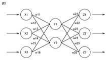
- FIG. 7 is a diagram showing the configuration of a neural network.
- the model generation unit 103 learns the open / closed state of the opening of the air conditioning management space by, for example, according to a neural network model, by so-called supervised learning.
- supervised learning refers to a method of learning a feature in the learning data by giving a set of data of an input and a result (label) to the learning device 101, and inferring the result from the input.
- a neural network is composed of an input layer consisting of a plurality of neurons, an intermediate layer (hidden layer) consisting of a plurality of neurons, and an output layer consisting of a plurality of neurons.
- the intermediate layer may be one layer or two or more layers.
- the values are multiplied by the weights W1 (w11 to w16) and input to the intermediate layers (Y1 to Y2). Then, the result is further multiplied by the weight W2 (w21 to w26) and output from the output layer (Z1 to Z3). This output result depends on the values of the weights W1 and W2.
- the neural network is learning to infer the open / closed state of the opening of the air conditioning management space from the data on the heat load in the air conditioning management space by so-called supervised learning according to the learning data acquired by the data acquisition unit 102. Generate a finished model.
- the neural network inputs data on the amount of heat load in the air conditioning management space to the input layer, and the result output from the output layer approaches the open / closed state (correct answer) of the opening of the air conditioning management space. Learning is done by adjusting the weights W1 and W2.
- the model generation unit 103 generates and outputs a trained model by executing the above learning.
- the trained model storage device 301 stores the trained model output from the model generation unit 103.
- FIG. 8 is a flowchart showing the learning procedure of the learning device 101.
- the data acquisition unit 102 acquires (correct answer) the open / closed state of the opening of the air conditioning management space input by the user through the operation input unit 104.
- the data acquisition unit 102 acquires data on the heat load amount in the air conditioning management space at the time when the open / closed state of the opening of the air conditioning management space input from the user through the operation input unit 104 is acquired from the air conditioning control unit 601. do.
- step b2 the model generation unit 103 learns that the data regarding the heat load amount in the air conditioning management space acquired by the data acquisition unit 102 and the open / closed state (correct answer) of the opening of the air conditioning management space are associated with each other. Based on the data, a trained model that infers the open / closed state of the opening of the air conditioning control space is generated from the data on the heat load in the air conditioning control space.
- step b3 the trained model storage device 301 stores the trained model generated by the model generation unit 103.
- FIG. 9 is a diagram showing the configuration of the inference device 201.
- the inference device 201 includes a data acquisition unit 202 and an inference unit 203.
- the data acquisition unit 202 acquires data on the amount of heat load in the air conditioning management space from the air conditioning control unit 601.
- the inference unit 203 uses the trained model stored in the trained model storage device 301 to open the air harmony management space from the data regarding the heat load in the air balance management space acquired by the data acquisition unit 202. Infer the open / closed state of. That is, the inference unit 203 is inferred from the data on the heat load in the air conditioning management space by inputting the data on the heat load in the air conditioning management space acquired by the data acquisition unit 202 into the trained model. It is possible to output the open / closed state of the opening of the air conditioning control space.
- FIG. 10 is a flowchart showing the inference procedure of the inference device 201.
- the data acquisition unit 202 acquires data regarding the amount of heat load in the air conditioning management space from the air conditioning control unit 601.
- step c2 the inference unit 203 uses the trained model stored in the trained model storage device 301 to perform air balance management from the data on the heat load in the air balance management space acquired by the data acquisition unit 202. Infer the open / closed state of the opening in the space.
- step c3 the inference unit 203 outputs the open / closed state of the opening of the air conditioning management space obtained by the trained model to the air conditioning control unit 601.
- step c4 when the opening of the air conditioning control space is closed, the process proceeds to step c5, and when the opening of the air conditioning control space is open, the process proceeds to step c6.
- step c5 the inference unit 203 notifies the air conditioning control unit 601 that the opening of the air conditioning management space is closed.
- step c6 the control device 600 notifies the air conditioning control unit 601 that the opening of the air conditioning management space is open.
- FIG. 11 is a flowchart showing the procedure of air conditioning control according to the first embodiment.
- the air conditioning control unit 601 starts the normal operation of the air conditioning device 1 and the ventilation device 13 based on the indoor target temperature and the indoor target humidity set by the user through the target temperature / humidity input unit 44.
- step S102 When the air conditioning control unit 601 receives the notification that the opening of the air conditioning management space is open in step S102, the process proceeds to step S103.
- step S103 the air conditioning control unit 601 starts dew condensation prevention control.
- the air conditioning control unit 601 receives the notification that the opening of the air conditioning management space is closed in step S104, the process proceeds to step S105.
- step S105 the air conditioning control unit 601 causes the air conditioning device 1 and the ventilation device 13 to resume normal operation.
- the air conditioning control unit 601 restarts the normal operation of the air conditioning device 1 and the ventilation device 13 based on the indoor target temperature and the indoor target humidity set by the user through the target temperature / humidity input unit 44. ..
- FIG. 12 is a flowchart showing the procedure of the dew condensation prevention control according to the first embodiment.
- the air conditioning control unit 601 acquires the indoor temperature Ta from the indoor temperature sensor 501 and the indoor humidity Xa from the indoor humidity sensor 502.
- step S202 when there is a candidate for a combination of the target temperature and the target humidity so that the air conditioning outlet does not condense, the process proceeds to step S203. If there is no candidate for a combination of the target temperature and the target humidity such that the air conditioning outlet does not condense dew, the process proceeds to step S207.
- step S203 the air conditioning control unit 601 calculates the air conditioning sensible heat load Q1 and the air conditioning latent heat load Q2 for each candidate.
- the air conditioning control unit 601 calculates the temperature difference ⁇ T between the room temperature Ta and the target temperature Ta_tgt set by the target temperature / humidity input unit 44 as the air conditioning sensible heat load Q1.
- the air conditioning control unit 601 calculates the outside air latent heat load Q2o using the target temperature Ta_tgt set by the target temperature / humidity input unit 44 based on the equation (1).
- the air conditioning control unit 601 calculates the latent heat load Q2m of the human body according to the equation (2).
- the air conditioning control unit 601 calculates the sum of the outside air latent heat load Q2o and the human body latent heat load Q2m as the air conditioning latent heat load Q2.
- step S204 the air conditioning control unit 601 refers to a predetermined table based on the air conditioning sensible heat load Q1 and the air conditioning latent heat load Q2 for each candidate, and refers to the power consumption of the air conditioning device 1 and the ventilation device. The sum Qxy with the power consumption of is obtained.
- step S205 the air conditioning control unit 601 sets the candidate having the smallest sum Qxy of power consumption as a combination of the indoor target temperature Ta_tgt and the indoor target humidity Xa_tgt.
- step S206 the air conditioning control unit 601 controls the air conditioning device 1 and the ventilation device 13 based on the combination of the indoor target temperature Ta_tgt and the indoor target humidity Xa_tgt.
- step S207 the air conditioning control unit 601 stops the circulation of the refrigerant of the air conditioning device 1 and the ventilation device 13, and causes the air conditioning device 1 and the ventilation device 13 to perform an air blowing operation.
- the air conditioning control unit 601 causes the air conditioning device 1 and the ventilation device 13 to perform the blowing operation by operating the indoor heat exchanger blower 8 and the air supply blower 10.
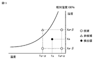
- FIG. 13 is a diagram showing the first example of a candidate for a combination of a target temperature and a target humidity so that the air conditioning outlet does not condense dew.
- the air conditioning control unit 601 sets a candidate for a combination of a target temperature in a plurality of rooms where the air conditioning outlet does not condense and a target humidity in the room based on the detected indoor temperature Ta and the detected indoor humidity Xa.
- the air conditioning control unit 601 is the air among the four vicinitys (Ta + ⁇ , Xa- ⁇ ), (Ta + ⁇ , Xa + ⁇ ), (Ta- ⁇ , Xa- ⁇ ), and (Ta- ⁇ , Xa + ⁇ ) of (Ta, Xa). If the relative humidity of the diagram is below the 100% curve, set it as a candidate for the combination of the target temperature and the target humidity so that the air conditioning outlet does not condense.
- ⁇ and ⁇ are predetermined values.
- the air conditioning equipment can be controlled according to the presence or absence of natural ventilation from the opening of the air conditioning management space.
- air conditioning control when it is detected that the opening is open, air conditioning control can be executed so as to prevent dew condensation while suppressing power consumption.
- the user When it is detected that the opening is open, the user may be notified not to forget to close the opening. If it is detected that the opening is closed, the user may be notified to open the opening to prevent virus infection.
- FIG. 14 is a diagram showing a second example of a candidate combination of a target temperature and a target humidity so that dew condensation does not occur on the air conditioning outlet.
- the temperature can be set to Tx or less during cooling operation.
- the air conditioning control unit 601 Based on the detected indoor temperature Ta and the detected indoor humidity Xa, the air conditioning control unit 601 sets candidates for a combination of a plurality of indoor target temperatures and indoor target humidity in which the air conditioning outlet does not condense.
- the air conditioning control unit 601 is the air among the four vicinitys (Ta + ⁇ , Xa- ⁇ ), (Ta + ⁇ , Xa + ⁇ ), (Ta- ⁇ , Xa- ⁇ ), and (Ta- ⁇ , Xa + ⁇ ) of (Ta, Xa). If the relative humidity of the diagram is below the 100% curve and the upper limit temperature Tx or less that can be set during cooling operation is set as a candidate for the combination of the target temperature and the target humidity so that the air conditioning outlet does not condense. do. However, ⁇ and ⁇ are predetermined values. In the example of FIG. 14, there is no candidate for a combination of the target temperature and the target humidity so that the air conditioning outlet does not condense dew.
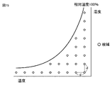
- FIG. 15 is a diagram showing a third example of a candidate combination of a target temperature and a target humidity so that dew condensation does not occur on the air conditioning outlet.
- the air conditioning control unit 601 sets the target temperature and the target humidity so that the air conditioning outlet does not condense at points on the grid at regular intervals d, where the relative humidity of the air diagram is below the curve of 100%. Set as a candidate for combination.
- FIG. 16 is a diagram showing the configuration of the air conditioning system 100 of the second embodiment.
- the difference between the air conditioning system 100 of the second embodiment and the air conditioning system 100 of the first embodiment is that the air conditioning system 100 of the second embodiment does not include the ventilation device 13.
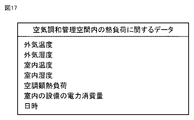
- FIG. 17 is a diagram showing data regarding the amount of heat load in the air conditioning management space according to the second embodiment.
- the data regarding the amount of heat load in the air conditioning control space in the second embodiment includes at least one of outside air temperature, outside air humidity, room temperature, room humidity, air conditioning sensible heat load, power consumption of room equipment, and date and time. include.
- the data regarding the heat load amount in the air conditioning control space does not have the latent heat load for air conditioning.
- the learning device 101 generates a trained model that infers the open / closed state of the opening of the air conditioning management space from the data related to the heat load shown in FIG.
- the inference device 201 inputs data regarding the heat load amount shown in FIG. 17 into the trained model, and outputs the open / closed state of the opening of the air conditioning management space.
- FIG. 18 is a flowchart showing the procedure of the dew condensation prevention control according to the second embodiment.
- the air conditioning control unit 601 acquires the indoor temperature Ta from the indoor temperature sensor 501 and the indoor humidity Xa from the indoor humidity sensor 502.
- step S302 when there is a candidate for a combination of the target temperature and the target humidity so that the air conditioning outlet does not condense, the process proceeds to step S303. If there is no candidate for a combination of the target temperature and the target humidity such that the air conditioning outlet does not condense dew, the process proceeds to step S307.
- step S303 the air conditioning control unit 601 calculates the air conditioning sensible heat load Q1 for each candidate.
- the air conditioning control unit 601 calculates the temperature difference ⁇ T between the room temperature Ta and the target temperature Ta_tgt set by the target temperature / humidity input unit 44 as the air conditioning sensible heat load Q1.
- step S304 the air conditioning control unit 601 obtains the power consumption Qx of the air conditioning device 1 for each candidate with reference to a predetermined table based on the air conditioning sensible heat load Q1.
- step S305 the air conditioning control unit 601 sets the candidate with the minimum power consumption Qx as a combination of the indoor target temperature Ta_tgt and the indoor target humidity Xa_tgt.
- step S306 the air conditioning control unit 601 controls the air conditioning device 1 based on the combination of the indoor target temperature Ta_tgt and the indoor target humidity Xa_tgt.
- step S307 the air conditioning control unit 601 causes the air conditioning device 1 to perform a ventilation operation. That is, the air conditioning control unit 601 stops the circulation of the refrigerant in the air conditioning system and operates the blower 8 for the indoor heat exchanger.
- FIG. 19 is a diagram showing the configuration of the air conditioning system 100 of the third embodiment.
- the difference between the air conditioning system 100 of the third embodiment and the air conditioning system of the first embodiment is that the air conditioning system 100 of the third embodiment includes an opening detection sensor 801.
- the opening detection sensor 801 detects the open / closed state of the air conditioning management space and outputs a detection signal indicating the open / closed state to the control panel 500.
- FIG. 20 is a diagram showing the configuration of the control panel 500 according to the third embodiment.
- the control panel 500 of the third embodiment does not include the learning device 101, the trained model storage device 301, and the inference device 201.
- the air conditioning control unit 601 receives a detection signal indicating the open / closed state of the air conditioning management space from the opening detection sensor 801.
- the air conditioning control unit 601 executes air conditioning control in the same manner as in the first embodiment based on the open / closed state of the air conditioning management space represented by the detection signal.
- the learning device 101 and the inference device 201 are provided inside the air conditioning system, they may be connected to the air conditioning system through a network and may be devices separate from the air conditioning system. Further, the learning device 101 and the inference device 201 may exist on the cloud server.
- the model generation unit 103 may learn the opening state of the opening according to the learning data created in the plurality of air conditioning systems.
- the model generation unit 103 may acquire learning data from a plurality of air conditioning systems used in the same area, or may acquire training data from a plurality of air conditioning systems operating independently in different areas. May be used to learn the opening state of the opening. It is also possible to add or remove an air conditioning system that collects learning data from the target on the way. Further, a learning device that has learned the open / closed state of the opening for one air conditioning system is applied to another air conditioning system, and the open / closed state of the opening is relearned and updated for this other air conditioning system. You may do so.
- model generation unit 103 As the learning algorithm in which the model generation unit 103 is used, deep learning that learns the extraction of the feature amount itself can also be used, and other known methods such as genetic programming, functional logic programming, or support vector can be used. Machine learning may be executed according to the machine or the like.
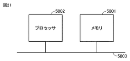
- FIG. 21 is a diagram showing a hardware configuration of the learning device 101, the inference device 201, or the control device 600.
- the learning device 101, the inference device 201, and the control device 600 can configure the corresponding operation with the hardware or software of the digital circuit.
- the functions of the learning device 101, the inference device 201, and the control device 600 are realized by using software
- the learning device 101, the inference device 201, and the control device 600 are, for example, as shown in FIG. 21, the bus 5003.
- the processor 5002 and the memory 5001 connected by the above are provided, and the program stored in the memory 5001 can be executed by the processor 5002.
- the inference device infers the open / closed state of the opening of the air conditioning management space from the input data acquired by the data acquisition unit using the trained model. It is not limited.
- the inference device may infer the open / closed state of the opening of the air conditioning management space from the input data acquired by the data acquisition unit based on rule-based inference or case-based inference.
- the control device 600 has a plurality of candidates for a combination of indoor target temperature and indoor target humidity in which the air conditioning outlet does not condense when the opening of the air conditioning control space is open. If not, the circulation of the refrigerant of the air conditioning equipment 200 is stopped and the air conditioning equipment 200 is operated by blowing air, but the present invention is not limited to this. In such a case, the control device 600 may also stop the ventilation operation of the air conditioning equipment 200.
Landscapes
- Engineering & Computer Science (AREA)
- Chemical & Material Sciences (AREA)
- Combustion & Propulsion (AREA)
- Mechanical Engineering (AREA)
- General Engineering & Computer Science (AREA)
- Signal Processing (AREA)
- Physics & Mathematics (AREA)
- Fuzzy Systems (AREA)
- Mathematical Physics (AREA)
- Air Conditioning Control Device (AREA)
Abstract
制御装置(600)は、空気調和管理空間の開口部が開いた状態である旨の通知を受けたときに、空調吹き出し口が結露しない複数の室内目標温度および室内目標湿度の組み合わせの候補のうち、消費電力が最小の候補を選択し、選択した候補に基づいて、空気調和設備(200)を制御する。
Description
本開示は、空気調和システムに関する。
従来から、室内の環境状態に応じて、室内の換気量を調整する換気制御装置が知られている。たとえば、特許文献1(特開平7-120022号公報)の換気制御装置は、室内の換気を行う換気扇と、室内の環境状態を検知する複数のセンサと、センサの出力値を入力層への入力とし、出力層に換気量を割当てて学習させたニューラルネットワークと、ニューラルネットワークの出力層の出力値から換気量を選択する判定部と、判定部の選択結果に基づいて換気扇の動作を制御する駆動制御部とを備える。
特許文献1に記載の換気制御装置は、換気量を最適化することができるが、人が窓などの空気調和管理空間の開口部を開けることによってランダムに発生する自然換気に応じた空気調和設備の制御ができない。
それゆえに、本開示の目的は、自然換気に応じた空気調和設備の制御が可能な空気調和システムを提供することである。
本開示の空気調和システムは、空気調和設備と、空気調和管理空間の開口部が開いた状態である旨の通知を受けたときに、空調吹き出し口が結露しない複数の室内目標温度および室内目標湿度の組み合わせの候補のうち、消費電力が最小の候補を選択し、選択した候補に基づいて、空気調和設備を制御する制御装置とを備える。
本開示の空気調和システムによれば、空調吹き出し口が結露しない複数の室内目標温度および室内目標湿度の組み合わせの候補のうち、消費電力が最小の候補を選択するので、自然換気に応じた空気調和設備の制御が可能である。
以下、実施の形態について、図面を参照して説明する。
実施の形態1.
図1は、実施の形態1の空気調和システム100の構成を表わす図である。
実施の形態1.
図1は、実施の形態1の空気調和システム100の構成を表わす図である。
空気調和システム100は、制御盤500と、空気調和設備200とを備える。実施の形態1において、空気調和設備200は、内調機として動作する空気調和装置1と、外調機として動作する換気装置13とを備える。空気調和装置1は、主に空気調和管理空間である室内901の顕熱負荷を処理する。換気装置13は、空気調和管理空間である室内901の換気と主に室内901の潜熱負荷の処理とを行なう。
図2は、実施の形態1の制御盤500の構成を表わす図である。
制御盤500は、目標温湿度入力部44と、制御装置600と、学習装置101と、学習済みモデル記憶装置301と、推論装置201とを備える。制御装置600は、空気調和制御部601と、表示装置701とを備える。
制御盤500は、目標温湿度入力部44と、制御装置600と、学習装置101と、学習済みモデル記憶装置301と、推論装置201とを備える。制御装置600は、空気調和制御部601と、表示装置701とを備える。
制御装置600は、空気調和管理空間の開口部が開いた状態である旨の通知を受けたときに、空調吹き出し口が結露しない複数の室内目標温度および室内目標湿度の組み合わせの候補のうち、消費電力が最小の候補を選択し、選択した候補に基づいて、空気調和設備200を制御する。空気調和和管理空間とは、たとえば室内である。開口部とは、窓、ドア、またはシャッタなどである。開閉状態とは、開いている状態、または閉じている状態である。
制御装置600は、空気調和管理空間の開口部が開いた状態のときに、空調吹き出し口が結露しない複数の室内目標温度および室内目標湿度の組み合わせの候補が存在しない場合には、空気調和設備200の冷媒の循環を停止させるとともに、空気調和設備200を送風運転させる。
制御装置600は、空気調和管理空間の開口部が開いた状態である旨の通知を受けた後、空気調和管理空間の開口部が閉じた状態である旨の通知を受けたときには、空気調和管理空間の開口部が開いた状態である旨の通知を受ける前に目標温湿度入力部44を通じてユーザによって設定された室内目標温度および室内目標湿度に基づいて、空気調和設備200を制御する。
空気調和装置1は、複数の室内機11と室外機12とを備える。室外機12は室外に設置されている。室内機11は室内901に設置されている。室外機12及び各室内機11のそれぞれは、伝送線903により制御装置600に接続される。換気装置13は、伝送線903により制御装置600に接続される。
図3は、空気調和システム100の冷媒回路の概略図である。
空気調和装置1は、圧縮機2と、四方弁3と、室外熱交換器4と、膨張弁5と、室内熱交換器6とを備える。これらが順次配管で接続され、冷媒が循環するように構成された冷凍サイクルが形成される。空気調和装置1は、さらに、室外熱交換器用送風機7及び室内熱交換器用送風機8を備える。
空気調和装置1は、圧縮機2と、四方弁3と、室外熱交換器4と、膨張弁5と、室内熱交換器6とを備える。これらが順次配管で接続され、冷媒が循環するように構成された冷凍サイクルが形成される。空気調和装置1は、さらに、室外熱交換器用送風機7及び室内熱交換器用送風機8を備える。
室外機12に、圧縮機2、四方弁3、室外熱交換器4及び室外熱交換器用送風機7が設置される。室内機11に、膨張弁5、室内熱交換器6及び室内熱交換器用送風機8が設置される。
室外機12に蒸発温度検出装置31が設けられている。各室内機11のそれぞれに、室内機11の吸込空気の温湿度を検出する吸込温湿度検出装置32が設けられている。
換気装置13は、換気装置搭載膨張弁5a及び換気装置用冷却器9を備える。互いに直列に接続された換気装置搭載膨張弁5a及び換気装置用冷却器9が、膨張弁5及び室内熱交換器6に並列に接続されている。換気装置13には、換気装置用冷却器9に空気を通過させるための給気用送風機10が設置される。
空気調和装置1は、圧縮機2から吐出した冷媒の流れ方向を四方弁3により切り換えて冷房運転又は暖房運転に切り換え可能に構成される。四方弁3が図3の実線側に切り換えられた場合、室内熱交換器6及び換気装置用冷却器9が蒸発器、室外熱交換器4が凝縮器となり冷房運転が実施される。四方弁3を図3の点線側に切り換えられた場合、室内熱交換器6が凝縮器、室外熱交換器4が蒸発器となり暖房運転が実施される。図3には、冷房運転時の冷媒の流れが示されている。
図4は、換気装置13の概略構成を示す図である。
換気装置13は、本体ケーシング13a内に、換気装置用冷却器9と、全熱交換器22と、給気用送風機10と、排気用送風機21とを備える。本体ケーシング13a内には、給気通風路Aと排気通風路Bとが互いに独立して形成されている。給気通風路Aは、給気用送風機10により室外空気OAを取り入れて全熱交換器22及び換気装置用冷却器9に通過させ、調整空気SAとして室内901に供給する。排気通風路Bは、排気用送風機21により室内空気RAを取り入れて全熱交換器22に通過させ、排気EAとして室外に排気する。以下では、給気通風路Aにおいて全熱交換器22を通過した後、換気装置用冷却器9に流入する空気を冷却器流入空気IAという。
換気装置13は、本体ケーシング13a内に、換気装置用冷却器9と、全熱交換器22と、給気用送風機10と、排気用送風機21とを備える。本体ケーシング13a内には、給気通風路Aと排気通風路Bとが互いに独立して形成されている。給気通風路Aは、給気用送風機10により室外空気OAを取り入れて全熱交換器22及び換気装置用冷却器9に通過させ、調整空気SAとして室内901に供給する。排気通風路Bは、排気用送風機21により室内空気RAを取り入れて全熱交換器22に通過させ、排気EAとして室外に排気する。以下では、給気通風路Aにおいて全熱交換器22を通過した後、換気装置用冷却器9に流入する空気を冷却器流入空気IAという。
換気装置13は更に、冷却器流入空気IAの温度及び湿度を検出する冷却器流入温湿度検出装置23と、室内空気RAのCO2濃度を検出するCO2濃度検出装置24と、換気風量検出装置25とを備える。これらの検出装置23~25の検出値は、伝送線903を介して制御装置600に出力される。
全熱交換器22は、例えば互いに直交する通風路が交互に積層された構造を有する。全熱交換器22の通風路に室内空気RAと室外空気OAとが通過することによって両気流の間で全熱交換が行われる。換気装置用冷却器9は、上述したように冷凍サイクルの蒸発器で構成され、自身を通過する空気を露点温度以下に冷却して除湿する。換気装置13は、全熱交換器22と換気装置用冷却器9とにより室内901の潜熱負荷を処理する。
給気用送風機10及び排気用送風機21は、回転数制御により換気装置13内を流れる空気の風量を制御する。
このように構成された換気装置13では、室内901の環境(空気質、例えばCO2濃度)を良好に保つ(例えば、CO2濃度を1000ppm以下に保つ)ための必要換気量(風量VA)で換気が行われるように、制御装置600により給気用送風機10及び排気用送風機21の回転数が制御される。換気装置13は、室外空気OAを、給気通風路Aの全熱交換器22及び換気装置用冷却器9に通過させて除湿した上で室内901に供給する一方、室内空気RAを排気通風路Bに通過させて室外に排気することで、室内901の潜熱負荷を処理する。
空気調和システム100は、さらに、室内温度センサ501と、室内湿度センサ502と、室外温度センサ503と、室外湿度センサ504とを備える。
室内温度センサ501、および室内湿度センサ502は、室内に配置され、室外温度センサ503、および室外湿度センサ504は、室外に配置される。
制御装置600は、室内温度センサ501、室内湿度センサ502、室外温度センサ503、および室外湿度センサ504のそれぞれと、伝送線903で接続されている。
室内温度センサ501は、室内温度Taを検出する。室外温度センサ503は、外気温度Tbを検出する。目標温湿度入力部44は、ユーザの操作に基づいて、室内の目標温度Ta_tgtを設定する。
室内湿度センサ502は、室内湿度Xaを検出する。室外湿度センサ504は、外気湿度Xbを検出する。目標温湿度入力部44は、ユーザの操作に基づいて、室内の目標湿度Xa_tgtを設定する。
空気調和制御部601は、空気調和装置1内の検出装置31、32の検出値、および換気装置13の検出装置23~25の検出値に基づいて、空気調和制御を実行する。
空気調和制御部601は、室内温度センサ501によって検出された室内温度Taと、目標温湿度入力部44で設定された目標温度Ta_tgtとの温度差ΔTを空調顕熱負荷Q1として算出する。
空気調和制御部601は、以下の式によって、外気潜熱負荷Q2oを算出する。
Q2o=VA×ρa×(Xa_o-Xa_tgt)・・・(1)
VAは、換気風量検出装置25によって検出された換気風量、Xa_oは、全熱交換器22を通過後の空気の湿度、ρaは、空気の密度を表わす。
Q2o=VA×ρa×(Xa_o-Xa_tgt)・・・(1)
VAは、換気風量検出装置25によって検出された換気風量、Xa_oは、全熱交換器22を通過後の空気の湿度、ρaは、空気の密度を表わす。
空気調和制御部601は、以下の式によって、人体潜熱負荷Q2mを算出する。
Q2m=Qi×N・・・(2)
Qiは1人当りの潜熱負荷、Nは在室人数である。在室人数Nは、CO2濃度、換気風量検出装置25の検出値VA、または人感センサなどを用いて求めることができる。
Q2m=Qi×N・・・(2)
Qiは1人当りの潜熱負荷、Nは在室人数である。在室人数Nは、CO2濃度、換気風量検出装置25の検出値VA、または人感センサなどを用いて求めることができる。
空気調和制御部601は、外気潜熱負荷Q2oと人体潜熱負荷Q2mとの和を空調潜熱負荷Q2として算出する。
Q2=Q2o+Q2m・・・(3)
学習済みモデル記憶装置301は、空気調和管理空間内の熱負荷量に関するデータから、空気調和管理空間の開口部の開閉状態を推論する学習済みモデルを記憶する。
学習済みモデル記憶装置301は、空気調和管理空間内の熱負荷量に関するデータから、空気調和管理空間の開口部の開閉状態を推論する学習済みモデルを記憶する。
学習装置101は、学習済みモデルを生成して、学習済みモデル記憶装置301に記憶させる。
図5は、実施の形態1における空気調和管理空間内の熱負荷量に関するデータを表わす図である。実施の形態1における空気調和管理空間内の熱負荷量に関するデータは、外気温度、外気湿度、室内温度、室内湿度、空調顕熱負荷、空調潜熱負荷、室内の設備の電力消費量および日時のうち少なくとも1つを含む。これらの空気調和管理空間内の熱負荷量に関するデータは、空気調和管理空間の開口部の開閉状態との間の関連性が高い。
空気調和制御部601は、室外温度センサ503から外気温度Tbを取得する。空気調和制御部601は、室外湿度センサ504から外気湿度Xbを取得する。空気調和制御部601は、室内温度センサ501から室内温度Taを取得する。空気調和制御部601は、室内湿度センサ502から室内湿度Xaを取得する。
空気調和制御部601は、室内温度Taと、目標温湿度入力部44で設定された目標温度Ta_tgtとの温度差ΔTを空調顕熱負荷Q1として算出する。
空気調和制御部601は、式(1)~(3)に従って、空調潜熱負荷Q2を算出する。
空気調和制御部601は、配電盤などから室内の設備の電力消費量を取得する。室内の設備の電力消費量は、空気調和システム、照明機器、パソコン、およびディスプレイなどの電力消費量を含む。空気調和制御部601は、内部のタイマなどによって日時を取得する。
空気調和制御部601は、配電盤などから室内の設備の電力消費量を取得する。室内の設備の電力消費量は、空気調和システム、照明機器、パソコン、およびディスプレイなどの電力消費量を含む。空気調和制御部601は、内部のタイマなどによって日時を取得する。
外気温度、外気湿度、室内温度、室内湿度、空調顕熱負荷、空調潜熱負荷、室内の設備の電力消費量および日時は、空気調和制御部601から学習装置101および推論装置201に送られる。
推論装置201は、学習済みモデル記憶装置301に記憶させている学習済みモデルを用いて、空気調和管理空間の開口部の開閉状態を推論する。
図6は、学習装置101の構成を表わす図である。学習装置101は、操作入力部104、データ取得部102、およびモデル生成部103を備える。
操作入力部104は、ユーザが現在の開口部の開閉状態を入力し、制御装置600へ出力する。
データ取得部102は、操作入力部104から、空気調和管理空間の開口部の開閉状態を(正解)を取得する。たとえば、開いた状態を「0」、閉じた状態を「1」とする。データ取得部102は、操作入力部104から空気調和管理空間の開口部の開閉状態を取得した時点の空気調和管理空間内の熱負荷量に関するデータを空気調和制御部601から取得する。
モデル生成部103は、データ取得部102が取得した空気調和管理空間内の熱負荷量に関するデータと、空気調和管理空間の開口部の開閉状態(正解)とが互いに関連付けられた学習用データに基づいて、空気調和管理空間内の熱負荷量に関するデータから、空気調和管理空間の開口部の開閉状態を推論する学習済みモデルを生成する。
モデル生成部103が用いる学習アルゴリズムとして、教師あり学習、教師なし学習、または強化学習等の公知のアルゴリズムを用いることができる。一例として、ニューラルネットワークを適用した場合について説明する。
図7は、ニューラルネットワークの構成を表わす図である。
モデル生成部103は、例えば、ニューラルネットワークモデルに従って、いわゆる教師あり学習により、空気調和管理空間の開口部の開閉状態を学習する。ここで、教師あり学習とは、入力と結果(ラベル)のデータの組を学習装置101に与えることによって、それらの学習用データにある特徴を学習し、入力から結果を推論する手法をいう。
モデル生成部103は、例えば、ニューラルネットワークモデルに従って、いわゆる教師あり学習により、空気調和管理空間の開口部の開閉状態を学習する。ここで、教師あり学習とは、入力と結果(ラベル)のデータの組を学習装置101に与えることによって、それらの学習用データにある特徴を学習し、入力から結果を推論する手法をいう。
ニューラルネットワークは、複数のニューロンからなる入力層、複数のニューロンからなる中間層(隠れ層)、及び複数のニューロンからなる出力層によって構成される。中間層は、1層、又は2層以上でもよい。
例えば、3層のニューラルネットワークであれば、複数の入力が入力層(X1~X3)に入力されると、その値に重みW1(w11~w16)を掛けて中間層(Y1~Y2)に入力され、その結果にさらに重みW2(w21~w26)を掛けて出力層(Z1~Z3)から出力される。この出力結果は、重みW1とW2の値によって変わる。
ニューラルネットワークは、データ取得部102によって取得される学習用データに従って、いわゆる教師あり学習により、空気調和管理空間内の熱負荷量に関するデータから、空気調和管理空間の開口部の開閉状態を推論する学習済みモデルを生成する。
すなわち、ニューラルネットワークは、入力層に空気調和管理空間内の熱負荷量に関するデータを入力して出力層から出力された結果が、空気調和管理空間の開口部の開閉状態(正解)に近づくように重みW1とW2を調整することで学習する。
モデル生成部103は、以上のような学習を実行することで学習済みモデルを生成し、出力する。
学習済みモデル記憶装置301は、モデル生成部103から出力された学習済みモデルを記憶する。
図8は、学習装置101の学習手順を表わすフローチャートである。
ステップb1において、データ取得部102は、操作入力部104を通じて、ユーザが入力する空気調和管理空間の開口部の開閉状態を(正解)を取得する。データ取得部102は、操作入力部104を通じてユーザから入力される空気調和管理空間の開口部の開閉状態を取得した時点の空気調和管理空間内の熱負荷量に関するデータを空気調和制御部601から取得する。
ステップb1において、データ取得部102は、操作入力部104を通じて、ユーザが入力する空気調和管理空間の開口部の開閉状態を(正解)を取得する。データ取得部102は、操作入力部104を通じてユーザから入力される空気調和管理空間の開口部の開閉状態を取得した時点の空気調和管理空間内の熱負荷量に関するデータを空気調和制御部601から取得する。
ステップb2において、モデル生成部103は、データ取得部102が取得した空気調和管理空間内の熱負荷量に関するデータと、空気調和管理空間の開口部の開閉状態(正解)とが互いに関連付けられた学習用データに基づいて、空気調和管理空間内の熱負荷量に関するデータから、空気調和管理空間の開口部の開閉状態を推論する学習済みモデルを生成する。
ステップb3において、学習済みモデル記憶装置301は、モデル生成部103が生成した学習済みモデルを記憶する。
図9は、推論装置201の構成を表わす図である。推論装置201は、データ取得部202、および推論部203を備える。
データ取得部202は、空気調和管理空間内の熱負荷量に関するデータを空気調和制御部601から取得する。
推論部203は、学習済みモデル記憶装置301に記憶されている学習済みモデルを利用して、データ取得部202によって取得した空気調和管理空間内の熱負荷量に関するデータから空気調和管理空間の開口部の開閉状態を推論する。すなわち、推論部203は、学習済みモデルにデータ取得部202で取得した空気調和管理空間内の熱負荷量に関するデータを入力することによって、空気調和管理空間内の熱負荷量に関するデータから推論される空気調和管理空間の開口部の開閉状態を出力することができる。
図10は、推論装置201の推論手順を表わすフローチャートである。
ステップc1において、データ取得部202は、空気調和管理空間内の熱負荷量に関するデータを空気調和制御部601から取得する。
ステップc1において、データ取得部202は、空気調和管理空間内の熱負荷量に関するデータを空気調和制御部601から取得する。
ステップc2において、推論部203は、学習済みモデル記憶装置301に記憶されている学習済みモデルを利用して、データ取得部202によって取得した空気調和管理空間内の熱負荷量に関するデータから空気調和管理空間の開口部の開閉状態を推論する。
ステップc3において、推論部203は、学習済みモデルにより得られた空気調和管理空間の開口部の開閉状態を空気調和制御部601に出力する。
ステップc4において、空気調和管理空間の開口部が閉じた状態の場合に、処理がステップc5に進み、空気調和管理空間の開口部が開いた状態の場合に、処理がステップc6に進む。
ステップc5において、推論部203は、空気調和管理空間の開口部が閉じた状態であることを空気調和制御部601に通知する。ステップc6において、制御装置600は、空気調和管理空間の開口部が開いた状態であることを空気調和制御部601に通知する。
図11は、実施の形態1の空気調和制御の手順を表わすフローチャートである。
ステップS101において、空気調和制御部601は、目標温湿度入力部44を通じてユーザによって設定された室内目標温度および室内目標湿度に基づいて、空気調和装置1および換気装置13の通常運転を開始させる。
ステップS101において、空気調和制御部601は、目標温湿度入力部44を通じてユーザによって設定された室内目標温度および室内目標湿度に基づいて、空気調和装置1および換気装置13の通常運転を開始させる。
ステップS102において、空気調和制御部601が、空気調和管理空間の開口部が開いた状態である旨の通知を受信した場合には、処理がステップS103に進む。
ステップS103において、空気調和制御部601は、結露防止制御を開始する。
ステップS104において、空気調和制御部601が、空気調和管理空間の開口部が閉じた状態である旨の通知を受信した場合には、処理がステップS105に進む。
ステップS104において、空気調和制御部601が、空気調和管理空間の開口部が閉じた状態である旨の通知を受信した場合には、処理がステップS105に進む。
ステップS105において、空気調和制御部601は、空気調和装置1および換気装置13に通常運転を再開させる。空気調和制御部601は、ステップS102の前において、目標温湿度入力部44を通じてユーザによって設定された室内目標温度および室内目標湿度に基づいて、空気調和装置1および換気装置13の通常運転を再開させる。
図12は、実施の形態1の結露防止制御の手順を表わすフローチャートである。
ステップS201において、空気調和制御部601は、空気調和制御部601は、室内温度センサ501から室内温度Taを取得し、室内湿度センサ502から室内湿度Xaを取得する。
ステップS201において、空気調和制御部601は、空気調和制御部601は、室内温度センサ501から室内温度Taを取得し、室内湿度センサ502から室内湿度Xaを取得する。
ステップS202において、空調吹き出し口が結露しないような目標温度と目標湿度との組み合わせの候補が存在する場合に、処理がステップS203に進む。空調吹き出し口が結露しないような目標温度と目標湿度との組み合わせの候補が存在しない場合に、処理がステップS207に進む。
ステップS203において、空気調和制御部601は、各候補について、空調顕熱負荷Q1および空調潜熱負荷Q2を算出する。空気調和制御部601は、室内温度Taと、目標温湿度入力部44で設定された目標温度Ta_tgtとの温度差ΔTを空調顕熱負荷Q1として算出する。空気調和制御部601は、式(1)に基づいて、目標温湿度入力部44で設定された目標温度Ta_tgtを用いて、外気潜熱負荷Q2oを算出する。空気調和制御部601は、式(2)に従って、人体潜熱負荷Q2mを算出する。空気調和制御部601は、外気潜熱負荷Q2oと人体潜熱負荷Q2mとの和を空調潜熱負荷Q2として算出する。
ステップS204において、空気調和制御部601は、各候補について、その空調顕熱負荷Q1および空調潜熱負荷Q2に基づいて、予め定められたテーブルを参照して、空気調和装置1の消費電力と換気装置の消費電力との和Qxyを求める。
ステップS205において、空気調和制御部601は、消費電力の和Qxyが最小の候補を室内の目標温度Ta_tgt、および室内の目標湿度Xa_tgtの組み合わせに設定する。
ステップS206において、空気調和制御部601は、室内の目標温度Ta_tgt、および室内の目標湿度Xa_tgtの組み合わせに基づいて、空気調和装置1および換気装置13を制御する。
ステップS207において、空気調和制御部601は、空気調和装置1および換気装置13の冷媒の循環を停止させるとともに、空気調和装置1および換気装置13に送風運転をさせる。空気調和制御部601は、室内熱交換器用送風機8および給気用送風機10を運転させることによって、空気調和装置1および換気装置13に送風運転をさせる。
図13は、空調吹き出し口が結露しないような目標温度と目標湿度との組み合わせの候補の第1の例を表わす図である。
空気調和制御部601は、検出された室内温度Ta、および検出された室内湿度Xaに基づいて、空調吹き出し口が結露しない複数の室内の目標温度および室内の目標湿度の組み合わせの候補を設定する。空気調和制御部601は、(Ta,Xa)の4近傍(Ta+α、Xa-β)、(Ta+α、Xa+β)、(Ta-α、Xa-β)、(Ta-α、Xa+β)のうち、空気線図の相対湿度が100%の曲線よりも下側にあるものを空調吹き出し口が結露しないような目標温度と目標湿度との組み合わせの候補に設定する。ただし、αおよびβは、予め定められた値である。
本実施の形態によれば、空気調和管理空間の開口部からの自然換気の有無に応じて、空気調和設備を制御することができる。本実施の形態では、開口部が開いていることが検出された場合に、消費電力を抑制しつつ、結露を防止するように空気調和制御を実行することができる。
なお、開口部が開いていることが検出された場合に、開口部の閉め忘れしないようにユーザに通知してもよい。開口部が閉じていることが検出された場合に、ウイルスの感染防止のために開口部を開くようにユーザに通知してもよい。
実施の形態1の変形例1.
図14は、空調吹き出し口が結露しないような目標温度と目標湿度との組み合わせの候補の第2の例を表わす図である。
図14は、空調吹き出し口が結露しないような目標温度と目標湿度との組み合わせの候補の第2の例を表わす図である。
冷房運転時において、Tx以下の温度に設定が可能であるとする。空気調和制御部601は、検出された室内温度Ta、および検出された室内湿度Xaに基づいて、空調吹き出し口が結露しない複数の室内目標温度および室内目標湿度の組み合わせの候補を設定する。
空気調和制御部601は、(Ta,Xa)の4近傍(Ta+α、Xa-β)、(Ta+α、Xa+β)、(Ta-α、Xa-β)、(Ta-α、Xa+β)のうち、空気線図の相対湿度が100%の曲線よりも下側にあり、かつ冷房運転時に設定可能上限温度Tx以下のものを空調吹き出し口が結露しないような目標温度と目標湿度との組み合わせの候補に設定する。ただし、αおよびβは、予め定められた値である。図14の例では、空調吹き出し口が結露しないような目標温度と目標湿度との組み合わせの候補が存在しない。
実施の形態1の変形例2.
図15は、空調吹き出し口が結露しないような目標温度と目標湿度との組み合わせの候補の第3の例を表わす図である。
図15は、空調吹き出し口が結露しないような目標温度と目標湿度との組み合わせの候補の第3の例を表わす図である。
空気調和制御部601は、空気線図の相対湿度が100%の曲線よりも下側にある、一定間隔dごとの格子上の点を空調吹き出し口が結露しないような目標温度と目標湿度との組み合わせの候補に設定する。
実施の形態2.
図16は、実施の形態2の空気調和システム100の構成を表わす図である。
図16は、実施の形態2の空気調和システム100の構成を表わす図である。
実施の形態2の空気調和システム100が、実施の形態1の空気調和システム100と相違する点は、実施の形態2の空気調和システム100は、換気装置13を備えない点である。
図17は、実施の形態2における空気調和管理空間内の熱負荷量に関するデータを表わす図である。実施の形態2における空気調和管理空間内の熱負荷量に関するデータは、外気温度、外気湿度、室内温度、室内湿度、空調顕熱負荷、室内の設備の電力消費量および日時のうち少なくとも1つを含む。実施の形態2では、実施の形態1と異なり、空気調和管理空間内の熱負荷量に関するデータは、空調潜熱負荷を有さない。
学習装置101は、図17に示す熱負荷量に関するデータから、空気調和管理空間の開口部の開閉状態を推論する学習済みモデルを生成する。推論装置201は、学習済みモデルに図17に示す熱負荷量に関するデータを入力して、空気調和管理空間の開口部の開閉状態を出力する。
図18は、実施の形態2の結露防止制御の手順を表わすフローチャートである。
ステップS301において、空気調和制御部601は、空気調和制御部601は、室内温度センサ501から室内温度Taを取得し、室内湿度センサ502から室内湿度Xaを取得する。
ステップS301において、空気調和制御部601は、空気調和制御部601は、室内温度センサ501から室内温度Taを取得し、室内湿度センサ502から室内湿度Xaを取得する。
ステップS302において、空調吹き出し口が結露しないような目標温度と目標湿度との組み合わせの候補が存在する場合に、処理がステップS303に進む。空調吹き出し口が結露しないような目標温度と目標湿度との組み合わせの候補が存在しない場合に、処理がステップS307に進む。
ステップS303において、空気調和制御部601は、各候補について、空調顕熱負荷Q1を算出する。空気調和制御部601は、室内温度Taと、目標温湿度入力部44で設定された目標温度Ta_tgtとの温度差ΔTを空調顕熱負荷Q1として算出する。
ステップS304において、空気調和制御部601は、各候補について、その空調顕熱負荷Q1に基づいて、予め定められたテーブルを参照して、空気調和装置1の消費電力Qxを求める。
ステップS305において、空気調和制御部601は、消費電力Qxが最小の候補を室内の目標温度Ta_tgt、および室内の目標湿度Xa_tgtの組み合わせに設定する。
ステップS306において、空気調和制御部601は、室内の目標温度Ta_tgt、および室内の目標湿度Xa_tgtの組み合わせに基づいて、空気調和装置1を制御する。
ステップS307において、空気調和制御部601は、空気調和装置1に送風運転をさせる。すなわち、空気調和制御部601は、空気調和システム内の冷媒の循環を停止させるとともに、室内熱交換器用送風機8を運転させる。
実施の形態3.
図19は、実施の形態3の空気調和システム100の構成を表わす図である。
図19は、実施の形態3の空気調和システム100の構成を表わす図である。
実施の形態3の空気調和システム100が、実施の形態1の空気調和システムと相違する点は、実施の形態3の空気調和システム100は、開口部検出センサ801を備える点である。
開口部検出センサ801は、空気調和管理空間の開閉状態を検出して、開閉状態を表わす検出信号を制御盤500へ出力する。
図20は、実施の形態3の制御盤500の構成を表わす図である。
実施の形態3の制御盤500は、学習装置101、学習済みモデル記憶装置301、おおよび推論装置201を備えない。空気調和制御部601は、開口部検出センサ801から空気調和管理空間の開閉状態を表わす検出信号を受ける。空気調和制御部601は、検出信号で表される空気調和管理空間の開閉状態に基づいて、実施の形態1と同様にして空気調和制御を実行する。
実施の形態3の制御盤500は、学習装置101、学習済みモデル記憶装置301、おおよび推論装置201を備えない。空気調和制御部601は、開口部検出センサ801から空気調和管理空間の開閉状態を表わす検出信号を受ける。空気調和制御部601は、検出信号で表される空気調和管理空間の開閉状態に基づいて、実施の形態1と同様にして空気調和制御を実行する。
変形例.
(1)学習装置101及び推論装置201は、空気調和システムの内部に設けられるが、ネットワークを通じて、空気調和システムと接続され、空気調和システムとは別個の装置であってもよい。さらに、学習装置101及び推論装置201は、クラウドサーバ上に存在していてもよい。
(1)学習装置101及び推論装置201は、空気調和システムの内部に設けられるが、ネットワークを通じて、空気調和システムと接続され、空気調和システムとは別個の装置であってもよい。さらに、学習装置101及び推論装置201は、クラウドサーバ上に存在していてもよい。
(2)実施の形態では、モデル生成部103が用いる学習アルゴリズムに教師あり学習を適用した場合について説明したが、これに限られるものではない。学習アルゴリズムについては、教師あり学習以外にも、強化学習、教師なし学習、又は半教師あり学習等を適用することも可能である。
モデル生成部103は、複数の空気調和システムにおいて作成される学習用データに従って、開口部の開口状態を学習するようにしてもよい。モデル生成部103は、同一のエリアで使用される複数の空気調和システムから学習用データを取得してもよいし、異なるエリアで独立して動作する複数の空気調和システムから収集される学習用データを利用して開口部の開口状態を学習してもよい。また、学習用データを収集する空気調和システムを途中で対象に追加したり、対象から除去することも可能である。さらに、ある空気調和システムに関して開口部の開閉状態を学習した学習装置を、これとは別の空気調和システムに適用し、この別の空気調和システムに関して開口部の開閉状態を再学習して更新するようにしてもよい。
(3)モデル生成部103が用いられる学習アルゴリズムとしては、特徴量そのものの抽出を学習する、深層学習を用いることもでき、他の公知の方法、例えば遺伝的プログラミング、機能論理プログラミング、またはサポートベクターマシンなどに従って機械学習を実行してもよい。
(4)図21は、学習装置101、推論装置201、または制御装置600のハードウェア構成を表わす図である。
学習装置101、推論装置201、および制御装置600は、相当する動作をデジタル回路のハードウェアまたはソフトウェアで構成することができる。学習装置101、推論装置201、および制御装置600の機能をソフトウェアを用いて実現する場合には、学習装置101、推論装置201、および制御装置600は、例えば、図21に示すように、バス5003によって接続されたプロセッサ5002とメモリ5001とを備え、メモリ5001に記憶されたプログラムをプロセッサ5002が実行するようにすることができる。
(5)上記の実施形態では、推論装置は、学習済みモデルを用いて、データ取得部が取得した入力データから、空気調和管理空間の開口部の開閉状態を推論するものとしたが、これに限定するものではない。たとえば、推論装置は、ルールベース推論、または事例ベース推論に基づいて、データ取得部が取得した入力データから、空気調和管理空間の開口部の開閉状態を推論するものとしてもよい。
(6)上記の実施形態では、制御装置600は、空気調和管理空間の開口部が開いた状態のときに、空調吹き出し口が結露しない複数の室内目標温度および室内目標湿度の組み合わせの候補が存在しない場合には、空気調和設備200の冷媒の循環を停止させるとともに、空気調和設備200を送風運転させたが、これに限定されるものではない。このような場合には、制御装置600は、空気調和設備200の送風運転も停止するものとしてもよい。
今回開示された実施の形態はすべての点で例示であって制限的なものではないと考えられるべきである。本開示の範囲は上記した説明ではなくて請求の範囲によって示され、請求の範囲と均等の意味及び範囲内でのすべての変更が含まれることが意図される。
1 空気調和装置、2 圧縮機、3 四方弁、4 室外熱交換器、5 膨張弁、5a 換気装置搭載膨張弁、6 室内熱交換器、7 室外熱交換器用送風機、8 室内熱交換器用送風機、9 換気装置用冷却器、10 給気用送風機、11 室内機、12 室外機、13 換気装置、21 排気用送風機、22 全熱交換器、23 湿度検出装置、24 CO2濃度検出装置、25 換気風量検出装置、31 蒸発温度検出装置、32 吸込温湿度検出装置、44 目標温湿度入力部、100 空気調和システム、101 学習装置、102,202 データ取得部、103 モデル生成部、104 操作入力部、200 空気調和設備、201 推論装置、203 推論部、301 学習済みモデル記憶装置、500 制御盤、501 室内温度センサ、502 室内湿度センサ、503 室外温度センサ、504 室外湿度センサ、600 制御装置、601 空気調和制御部、701 表示装置、801 開口部検出センサ、901 室内、903 伝送線、5001 メモリ、5002 プロセッサ、5003 バス。
Claims (11)
- 空気調和設備と、
空気調和管理空間の開口部が開いた状態である旨の通知を受けたときに、空調吹き出し口が結露しない複数の室内目標温度および室内目標湿度の組み合わせの候補のうち、消費電力が最小の候補を選択し、選択した候補に基づいて、前記空気調和設備を制御する制御装置と、を備えた空気調和システム。 - 前記制御装置は、空気調和管理空間の開口部が開いた状態のときに、空調吹き出し口が結露しない複数の室内目標温度および室内目標湿度の組み合わせの候補が存在しない場合には、前記空気調和設備の冷媒の循環を停止させるとともに、前記空気調和設備を送風運転させる、請求項1記載の空気調和システム。
- 室内温度を検出する室内温度センサと、
室内湿度を検出する室内湿度センサと、をさらに備え、
前記制御装置は、検出された前記室内温度、および検出された前記室内湿度に基づいて、空調吹き出し口が結露しない複数の室内目標温度および室内目標湿度の組み合わせの候補を設定する、請求項1または2記載の空気調和システム。 - 前記制御装置は、前記開口部が開いた状態である旨の通知を受けた後、前記開口部が閉じた状態である旨の通知を受けたときには、前記開口部が開いた状態である旨の通知を受ける前に目標温湿度入力部を通じて設定された室内目標温度および室内目標湿度に基づいて、前記空気調和設備を制御する、請求項1~3のいずれか1項に記載の空気調和システム。
- 空気調和管理空間内の熱負荷量に関するデータから前記空気調和管理空間の開口部の開閉状態を推論し、前記制御装置に通知する推論装置をさらに備えた、請求項1~4のいずれか1項に記載の空気調和システム。
- 前記推論装置は、
空気調和管理空間内の熱負荷量に関するデータを取得するデータ取得部と、
前記空気調和管理空間内の熱負荷量に関するデータから前記空気調和管理空間の開口部の開閉状態を推論するための学習済みモデルに前記データ取得部が取得した熱負荷量に関するデータを入力して、前記空気調和管理空間の開口部の開閉状態を推論する推論部と、
を含む、請求項5記載の空気調和システム。 - 前記空気調和設備は、
空気調和装置と、
熱交換機能を有する換気装置と、を含み、
前記空気調和管理空間内の熱負荷量に関するデータは、外気温度、外気湿度、室内温度、室内湿度、空調顕熱負荷、空調潜熱負荷、室内の設備の電力消費量、および日時のうち少なくとも1つを含む、請求項6に記載の空気調和システム。 - 前記制御装置は、空調潜熱負荷および空調顕熱負荷に基づいて、前記消費電力を求める、請求項7記載の空気調和システム。
- 前記空気調和設備は、
空気調和装置を含み、
換気装置を含まず、
前記空気調和管理空間内の熱負荷量に関するデータは、外気温度、外気湿度、室内温度、室内湿度、空調顕熱負荷、室内の設備の電力消費量、および日時のうち少なくとも1つを含む、請求項6に記載の空気調和システム。 - 前記制御装置は、空調顕熱負荷に基づいて、前記消費電力を求める、請求項9記載の空気調和システム。
- 前記開口部は、窓、ドア、およびシャッタのうちのいずれかである、請求項1~10のいずれか1項に記載の空気調和システム。
Priority Applications (2)
| Application Number | Priority Date | Filing Date | Title |
|---|---|---|---|
| PCT/JP2020/047515 WO2022130634A1 (ja) | 2020-12-18 | 2020-12-18 | 空気調和システム |
| JP2022569675A JP7345687B2 (ja) | 2020-12-18 | 2020-12-18 | 空気調和システム |
Applications Claiming Priority (1)
| Application Number | Priority Date | Filing Date | Title |
|---|---|---|---|
| PCT/JP2020/047515 WO2022130634A1 (ja) | 2020-12-18 | 2020-12-18 | 空気調和システム |
Publications (1)
| Publication Number | Publication Date |
|---|---|
| WO2022130634A1 true WO2022130634A1 (ja) | 2022-06-23 |
Family
ID=82059288
Family Applications (1)
| Application Number | Title | Priority Date | Filing Date |
|---|---|---|---|
| PCT/JP2020/047515 WO2022130634A1 (ja) | 2020-12-18 | 2020-12-18 | 空気調和システム |
Country Status (2)
| Country | Link |
|---|---|
| JP (1) | JP7345687B2 (ja) |
| WO (1) | WO2022130634A1 (ja) |
Citations (4)
| Publication number | Priority date | Publication date | Assignee | Title |
|---|---|---|---|---|
| JP2017142013A (ja) * | 2016-02-10 | 2017-08-17 | 三菱電機株式会社 | 制御装置、制御システムおよびプログラム |
| JP2019043279A (ja) * | 2017-08-31 | 2019-03-22 | 株式会社デンソー | 埃濃度検出装置 |
| WO2019087264A1 (ja) * | 2017-10-30 | 2019-05-09 | 三菱電機株式会社 | 空気調和装置、制御方法およびプログラム |
| JP2020079784A (ja) * | 2014-03-03 | 2020-05-28 | パナソニック インテレクチュアル プロパティ コーポレーション オブ アメリカPanasonic Intellectual Property Corporation of America | 熱画像処理方法および熱画像処理装置 |
-
2020
- 2020-12-18 JP JP2022569675A patent/JP7345687B2/ja active Active
- 2020-12-18 WO PCT/JP2020/047515 patent/WO2022130634A1/ja active Application Filing
Patent Citations (4)
| Publication number | Priority date | Publication date | Assignee | Title |
|---|---|---|---|---|
| JP2020079784A (ja) * | 2014-03-03 | 2020-05-28 | パナソニック インテレクチュアル プロパティ コーポレーション オブ アメリカPanasonic Intellectual Property Corporation of America | 熱画像処理方法および熱画像処理装置 |
| JP2017142013A (ja) * | 2016-02-10 | 2017-08-17 | 三菱電機株式会社 | 制御装置、制御システムおよびプログラム |
| JP2019043279A (ja) * | 2017-08-31 | 2019-03-22 | 株式会社デンソー | 埃濃度検出装置 |
| WO2019087264A1 (ja) * | 2017-10-30 | 2019-05-09 | 三菱電機株式会社 | 空気調和装置、制御方法およびプログラム |
Also Published As
| Publication number | Publication date |
|---|---|
| JP7345687B2 (ja) | 2023-09-15 |
| JPWO2022130634A1 (ja) | 2022-06-23 |
Similar Documents
| Publication | Publication Date | Title |
|---|---|---|
| Karunakaran et al. | Energy efficient fuzzy based combined variable refrigerant volume and variable air volume air conditioning system for buildings | |
| Lee et al. | Deep-learning-based fault detection and diagnosis of air-handling units | |
| JP5759808B2 (ja) | サーバ室管理用の空調システムおよび空調制御方法 | |
| Kang et al. | A study on the control method of single duct VAV terminal unit through the determination of proper minimum air flow | |
| CN108131789B (zh) | 空调的换气控制方法及系统 | |
| JP2013148254A (ja) | 空調装置および空調制御方法 | |
| JP6937261B2 (ja) | 空調制御装置、空調制御方法及びコンピュータプログラム | |
| CN113039395B (zh) | 换气调整装置以及换气调整方法 | |
| JP2011242011A (ja) | サーバ用空調システム | |
| EP3862645A1 (en) | Air conditioner and method for controlling the same | |
| JP5404556B2 (ja) | 空気調和機の制御装置および冷凍装置の制御装置 | |
| JP2000088316A (ja) | 設定温度決定装置、空気調和装置およびプログラム記録媒体 | |
| JP2007271128A (ja) | 空調設備 | |
| JP6833057B2 (ja) | 空気調和装置、制御方法およびプログラム | |
| JP5602072B2 (ja) | サーバ室管理用の空調システム | |
| JP2015169399A (ja) | 換気装置 | |
| CN110686330A (zh) | 新风机复合空调系统及其控制方法 | |
| WO2022130634A1 (ja) | 空気調和システム | |
| JP2005301582A (ja) | プロセス管理装置 | |
| JP7002918B2 (ja) | 換気システム、空調システム、換気方法及びプログラム | |
| Kim et al. | A study on the control method without stratification of single duct VAV terminal units | |
| JP2014173795A (ja) | 換気システム | |
| WO2022130633A1 (ja) | 空気調和システムおよび空気調和システムの学習装置 | |
| JP2004271095A (ja) | 空調設備 | |
| JP2010196997A (ja) | 建物 |
Legal Events
| Date | Code | Title | Description |
|---|---|---|---|
| 121 | Ep: the epo has been informed by wipo that ep was designated in this application |
Ref document number: 20966020 Country of ref document: EP Kind code of ref document: A1 |
|
| ENP | Entry into the national phase |
Ref document number: 2022569675 Country of ref document: JP Kind code of ref document: A |
|
| NENP | Non-entry into the national phase |
Ref country code: DE |
|
| 122 | Ep: pct application non-entry in european phase |
Ref document number: 20966020 Country of ref document: EP Kind code of ref document: A1 |