WO2022130620A1 - 熱交換器および熱交換器の製造方法 - Google Patents
熱交換器および熱交換器の製造方法 Download PDFInfo
- Publication number
- WO2022130620A1 WO2022130620A1 PCT/JP2020/047427 JP2020047427W WO2022130620A1 WO 2022130620 A1 WO2022130620 A1 WO 2022130620A1 JP 2020047427 W JP2020047427 W JP 2020047427W WO 2022130620 A1 WO2022130620 A1 WO 2022130620A1
- Authority
- WO
- WIPO (PCT)
- Prior art keywords
- inorganic particles
- aluminum plate
- particles
- heat exchanger
- fluororesin
- Prior art date
- Legal status (The legal status is an assumption and is not a legal conclusion. Google has not performed a legal analysis and makes no representation as to the accuracy of the status listed.)
- Ceased
Links
Images


Classifications
-
- F—MECHANICAL ENGINEERING; LIGHTING; HEATING; WEAPONS; BLASTING
- F28—HEAT EXCHANGE IN GENERAL
- F28F—DETAILS OF HEAT-EXCHANGE AND HEAT-TRANSFER APPARATUS, OF GENERAL APPLICATION
- F28F13/00—Arrangements for modifying heat-transfer, e.g. increasing, decreasing
- F28F13/18—Arrangements for modifying heat-transfer, e.g. increasing, decreasing by applying coatings, e.g. radiation-absorbing, radiation-reflecting; by surface treatment, e.g. polishing
-
- F—MECHANICAL ENGINEERING; LIGHTING; HEATING; WEAPONS; BLASTING
- F28—HEAT EXCHANGE IN GENERAL
- F28F—DETAILS OF HEAT-EXCHANGE AND HEAT-TRANSFER APPARATUS, OF GENERAL APPLICATION
- F28F19/00—Preventing the formation of deposits or corrosion, e.g. by using filters or scrapers
- F28F19/02—Preventing the formation of deposits or corrosion, e.g. by using filters or scrapers by using coatings, e.g. vitreous or enamel coatings
- F28F19/04—Preventing the formation of deposits or corrosion, e.g. by using filters or scrapers by using coatings, e.g. vitreous or enamel coatings of rubber; of plastics material; of varnish
Definitions
- the present disclosure relates to a heat exchanger having aluminum fins and a method for manufacturing the heat exchanger.
- the heat exchanger has a structure in which a large number of fins (for example, an aluminum plate) are attached to a pipe through which the refrigerant passes, and the heat exchange efficiency is enhanced by the fins having a large surface area.
- Condensed water easily adheres to the surface of the fins during heating and cooling, and the phenomenon in which the fins are blocked by the condensed water (hereinafter referred to as "bridge phenomenon") increases ventilation resistance and reduces heat exchange efficiency.
- the bridging phenomenon is likely to occur when dirt such as dust adheres to the surface of the fins. Therefore, conventionally, the bridging phenomenon is prevented by forming an organic or inorganic hydrophilic film having excellent antifouling property on the surface of the fin.
- the term "antifouling property” as used herein means a performance in which stains are difficult to adhere and a performance in which the adhered stains are easily removed.
- Patent Document 1 a substrate made of aluminum and a resin coating film formed on the substrate and exposed on the surface thereof are provided, and the resin coating film has a saponification degree of 95.0 to 99.8%.
- the fluororesin particles (D) having a diameter of about 300 nm are contained and the mass of the resin coating film is 100 parts by mass
- the content of the polyethylene glycol (C) is 1.0 to 13 parts by mass.
- the content of the fluororesin particles (D) is 2.0 to 5.0 parts by mass
- the content of the polyvinyl alcohol (A) is the content of the acrylamide polymer (B) in terms of mass ratio.
- the amount is 0.3 to 0.6 times the amount ", a pre-coated fin material has been proposed.
- Patent Document 1 it is stated that antifouling property and hydrophilicity can be imparted to fins, but in heat exchangers, the antifouling property of fins and the maintenance of hydrophilicity for a long period of time are problems, and further. Improvement is required.
- the present disclosure has been made to solve the above-mentioned problems, and an object of the present disclosure is to provide a heat exchanger having antifouling property and long-lasting hydrophilicity, and a method for manufacturing the heat exchanger.
- the heat exchanger according to the present disclosure is a heat exchanger having aluminum fins arranged along the air flow direction, and the aluminum fins are an aluminum plate and an aluminum plate surface along the air flow direction in the aluminum plate.
- the hydrophilic layer is composed of bound inorganic particles and spherical inorganic particles having a structure in which small-diameter inorganic particles having a smaller diameter than the large-diameter inorganic particles are bound to the surface of the large-diameter inorganic particles.
- the water-repellent layer has a structure in which fluorine resin particles having an uneven structure are formed on the surface of a film having bound inorganic particles and spherical inorganic particles. It has.
- the method for manufacturing a heat exchanger according to the present disclosure is a method for manufacturing a heat exchanger having aluminum fins arranged along the flow direction of air, and is along the flow direction of air in an aluminum plate constituting the aluminum fins.
- a second step of imparting a hydrophilic composition having a bound inorganic particle having a structure in which small-diameter inorganic particles having a smaller diameter than the smaller diameter, a spherical inorganic particle, and a fluororesin particle are bound to form a hydrophilic layer, and a hydrophilic layer are formed. It has a third step of spraying a fluororesin particle powder on the end face of the
- the heat exchanger has excellent antifouling property against dust because the hydrophilic layer has a structure in which fluororesin particles are interspersed in a film having bound inorganic particles and spherical inorganic particles.
- the hydrophilic layer has spherical inorganic particles
- the heat exchanger has sustained hydrophilicity.
- the water-repellent layer has a structure in which a fluororesin film having an uneven structure is formed on the surface of a film having bound inorganic particles and spherical inorganic particles, the heat exchanger has antifouling property and sustained hydrophilicity. Have.
- FIG. It is a schematic block diagram of the heat exchanger which concerns on Embodiment 1.
- FIG. It is a schematic diagram of the aluminum fin of the heat exchanger which concerns on Embodiment 1.
- FIG. It is a schematic diagram of the surface of the aluminum fin of the heat exchanger which concerns on Embodiment 1.
- FIG. It is a schematic diagram of the end face of the aluminum fin of the heat exchanger which concerns on Embodiment 1.
- FIG. It is a schematic diagram which shows the cold spray apparatus used for manufacturing the heat exchanger which concerns on Embodiment 2.
- FIG. It is a schematic diagram of the uneven structure of the water-repellent layer in the heat exchanger according to the second embodiment.
- FIG. 1 is a schematic configuration diagram of the heat exchanger according to the first embodiment.
- FIG. 2 is a schematic view of aluminum fins of the heat exchanger according to the first embodiment.
- FIG. 3 is a schematic view of the surface of the aluminum fins of the heat exchanger according to the first embodiment.
- FIG. 4 is a schematic view of the end face of the aluminum fin of the heat exchanger according to the first embodiment.
- the heat exchanger 1 according to the first embodiment includes a refrigerant pipe 2 and aluminum fins 3 having antifouling properties.
- the aluminum fin 3 includes an aluminum plate 8, a corrosion-resistant resin layer 4, a hydrophilic layer 9, and a water-repellent layer 10.
- the surface in the direction along the air flow passing through the heat exchanger 1 is referred to as the aluminum fin surface 3a
- the surface perpendicular to the air flow passing through the heat exchanger 1 is referred to as the aluminum fin end surface 3b.
- the aluminum plate surface 8a and the aluminum plate end surface 8b are defined.
- the aluminum fin 3 according to the first embodiment has a structure in which the corrosion-resistant resin layer 4 is formed on the surface 8a of the aluminum plate and the hydrophilic layer 9 is formed on the surface of the corrosion-resistant resin layer 4. Further, the aluminum fin 3 according to the first embodiment has a structure in which the corrosion-resistant resin layer 4 is formed on the end surface 8b of the aluminum plate and the water-repellent layer 10 is formed on the surface of the corrosion-resistant resin layer 4.
- the aluminum fin 3 may further include a base treatment layer between the aluminum plate 8 and the corrosion-resistant resin layer 4.
- Each layer of the aluminum plate surface 8a may be formed only on one side surface of the aluminum plate 8 or may be formed on both side surfaces. The same applies to each layer of the aluminum fin end face 3b, and it may be formed only on one end face of the aluminum plate 8 or may be formed on both end faces.
- the water-repellent layer 10 is formed only on one end surface of the aluminum plate 8, it is formed on the end surface on the upstream side of the air flow. That is, the water-repellent layer 10 is formed at least on the end face of the aluminum plate on the upstream side of the air flow among the end faces 8b of the two sides of the aluminum plate 8.
- the aluminum plate 8 is made of pure aluminum or an aluminum alloy.
- 1000 series aluminum specified in JIS H 4000: 2014 can be preferably used from the viewpoint of thermal conductivity and workability. More specifically, aluminum having alloy numbers 1050, 1070 and 1200 is preferably used as the aluminum plate 8. However, a 2000 series to 9000 series aluminum alloy may be appropriately used as the aluminum plate 8.
- the plate thickness of the aluminum plate 8 may be appropriately determined according to the application and specifications of the heat exchanger 1. Specifically, the thickness of the aluminum plate 8 is preferably 0.08 mm or more and 0.3 mm or less from the viewpoint of appropriately ensuring workability to fins, strength of fins, thermal conductivity, and the like.
- the thickness of the aluminum plate 8 is 0.08 mm or more, it is possible to secure the strength required for a general fin material. On the other hand, if the plate thickness of the aluminum plate 8 is 0.3 mm or less, the workability to the fins can be ensured.
- the hydrophilic layer 9 is a layer having hydrophilicity and is a film having antifouling property.
- the hydrophilic layer 9 has the bound inorganic particles 5, the spherical inorganic particles 6, and the fluororesin particles 7. Since the hydrophilic layer 9 has the bound inorganic particles 5, it is possible to increase the contact area with the dew condensation water generated on the aluminum fins 3 during cooling. The contact area becomes large because the surface structure of the hydrophilic layer 9 has two fractal-like structures: a large uneven structure due to the presence of the bound inorganic particles 5 itself and a fine uneven structure on the surface of the bound inorganic particles 5. By taking.
- the aluminum fin surface 3a on which the hydrophilic layer 9 is formed has high hydrophilicity and can drain the dew condensation water generated on the surface of the aluminum fin 3. .
- the spherical inorganic particles 6 have an effect of enhancing the adhesion between the bound inorganic particles 5 and the corrosion-resistant resin layer 4 and an effect of maintaining hydrophilicity for a long period of time.
- the fluororesin particles 7 have an effect of suppressing adhesion of hydrophilic dust.
- the hydrophilic layer 9 has a structure in which fluororesin particles 7 are interspersed in a film having bound inorganic particles 5 and spherical inorganic particles 6.
- the film having the bound inorganic particles 5 and the spherical inorganic particles 6 is continuous without being divided by the fluororesin particles 7, and the area of the film having the bound inorganic particles 5 and the spherical inorganic particles 6 is the largest. It is sufficiently large compared to the area of the fluororesin particles 7 exposed on the surface.
- the hydrophilic layer 9 Since the film having the bound inorganic particles 5 and the spherical inorganic particles 6 is continuous, the hydrophilic layer 9 has a characteristic that water is very easy to spread when water droplets adhere to the surface of the hydrophilic layer.
- the hydrophilic layer 9 when the fluororesin particles 7 are connected to each other, are arranged close to each other, have a large area, or are unevenly distributed and a large number are locally arranged, the surface of the hydrophilic layer is covered. The spread of water is hindered.
- the hydrophilic layer 9 of the first embodiment maintains a highly hydrophilic state in which water easily spreads, and when viewed in a minute region related to the adhesion of contaminated particles, the fluororesin particles 7 are dispersed on the outermost surface. By having a scattered configuration, the hydrophilic portion and the hydrophobic portion coexist.
- the aluminum fin surface 3a having the hydrophilic layer 9 having such a structure can easily move moisture during moisture absorption and drying, and the hydrophilic particles and hydrophobic particles adhering to the aluminum fin surface 3a are lifted and released. It also has the effect of making it difficult to stick. That is, the aluminum fin surface 3a having the hydrophilic layer 9 has excellent antifouling property.
- the hydrophilic layer 9 has a property that water easily flows and spreads, it has the following effects. That is, in a situation where water flows on the aluminum fin surface 3a such as during dew condensation, rainfall, and cleaning, the substance adhering to the aluminum fin surface 3a flows together with the water flowing on the aluminum fin surface 3a and is very easily removed. There is also. From the above, the aluminum fin surface 3a having the hydrophilic layer 9 has excellent antifouling property, and the hydrophilic layer 9 has the spherical inorganic particles 6, so that the aluminum fin surface 3a having the hydrophilic layer 9 has continuous hydrophilicity. Will have.
- the water-repellent layer 10 is an oil-repellent water-repellent layer and is a film having antifouling properties.
- the water-repellent layer 10 has a structure in which a fluororesin film 10a having an uneven structure is formed on the surface of a film having the bound inorganic particles 5 and the spherical inorganic particles 6.
- the fluororesin film 10a is an antifouling film made of fluororesin particle powder.
- the aluminum fin end surface 3b can suppress the adhesion of oil smoke and the like due to the oil repellency and water repellency of the water repellent layer 10.
- the fluororesin film 10a has an uneven structure, the contact area between the surface of the water-repellent layer 10 and the particulate matter such as dust becomes small, so that the aluminum fin end surface 3b can also suppress the adhesion of dust. .. Further, since the water-repellent layer 10 has the bound inorganic particles 5, it has a microconcavo-convex structure capable of increasing the contact area with water. As a result, the aluminum fin end face 3b has high hydrophilicity, and the dew condensation water generated on the aluminum fin end face 3b can be drained.
- the corrosion-resistant resin layer 4 is a layer composed of a resin component for suppressing corrosion of the aluminum plate 8.
- the corrosion-resistant resin layer 4 may be configured to contain both an acrylic resin and an epoxy-based resin, or may be configured to include substantially only one of them. That is, the corrosion resistant resin layer 4 may be made of an acrylic resin or an epoxy resin.
- the content of the resin in the corrosion-resistant resin layer 4 is, for example, 90% by mass or more or 95% by mass or more. Further, the corrosion resistant resin layer 4 may contain other resins other than the acrylic resin and the epoxy resin, if necessary.
- Acrylic resin is a polymer having a structural unit derived from (meth) acrylic acid, (meth) acrylic acid ester, and the like.
- the acrylic resin may contain a crosslinked structure, and the crosslinked structure is formed from a monomer having a crosslinkable functional group.
- the crosslinkable functional group include an isocyanate group, an oxazoline group, a methylene group, a carbodiimide group, an aziridine group and the like.
- the crosslinked structure may be formed from melamine or the like.
- the resin composition containing the acrylic resin may be appropriately selected from commercially available products capable of forming a resin layer having metal adhesion. Examples of commercially available products include the Boncoat (registered trademark) series manufactured by DIC Corporation and the TOP series manufactured by Nihon Parkerizing Co., Ltd.
- the epoxy resin is a polymer composed of structural units derived from a monomer having an epoxy group in the molecule.
- the epoxy resin may contain a crosslinked structure, and the above-mentioned crosslinked structure is formed from a monomer having a crosslinkable functional group.
- the resin composition containing the epoxy resin may be appropriately selected from commercially available products capable of forming a resin layer having metal adhesion. Examples of commercially available products include EPICRON (registered trademark) manufactured by DIC Corporation.
- the corrosion-resistant resin layer 4 may contain one type of epoxy resin alone, or may contain two or more types in combination. Examples of other resins include polyester resins, ethylene acrylic resins, urethane resins and the like.
- the coating amount of the corrosion-resistant resin layer 4 is 0.05 mg / dm 2 or more, preferably 0.08 mg / dm 2 or more, and more preferably 0.10 mg / dm 2 or more.
- the amount of the corrosion-resistant resin layer 4 is 8.00 mg / dm 2 or less, preferably 6.00 mg / dm 2 or less, and more preferably 5.00 mg / dm 2 or less.
- the film amount of the corrosion-resistant resin layer 4 exceeds 8.00 mg / dm 2 , the hydrophilicity is lowered, and a high level of hydrophilicity cannot be ensured.
- the amount of the corrosion-resistant resin layer 4 is determined by the concentration of the coating composition used for the film formation of the corrosion-resistant resin layer 4 and the bar coater No. used for the film formation. It can be adjusted by selecting. Further, the amount of the film of the corrosion resistant resin layer 4 can be measured by a fluorescent X-ray, an infrared film thickness meter, mass measurement by film peeling, or the like. The method for adjusting and measuring the amount of the hydrophilic layer 9 and the fluororesin film 10a is the same as that for the corrosion-resistant resin layer 4 described above.
- the hydrophilic layer 9 has the bound inorganic particles 5, the spherical inorganic particles 6, and the fluororesin particles 7.
- Spherical inorganic particles 6 are SiO 2 , Al 2 O 3 , Sb 2 O 5 , ZrO 2 , TIO 2 , Fe 2 O 3 , CeO 2 , AgO, CuO, Cu 2 O, ZnO and composite oxides or mixtures thereof. It is composed of at least one selected from.
- the spherical inorganic particles 6 preferably have an average particle size of 5 nm or more and 30 nm or less.
- the spherical inorganic particles 6 are preferably hydrophilic silica particles or titanium particles. Since the silica is spherical particles, the hydrophilic effect can be further enhanced.
- the average particle size of the silica particles is preferably 5 nm or more and about 30 nm or less when measured by a light scattering method.
- the details of the method for producing the hydrophilic layer 9 will be described later, but the hydrophilic layer 9 is formed by applying a hydrophilic composition, which is a liquid coating solution, to an aluminum plate 8 and drying it.
- Silica particles having an average particle size in the range of 5 nm or more and 30 nm or less have a surface portion corresponding to approximately 15 to 30% of the weight of the silica particles for one silica particle, which is half water in the hydrophilic composition. It is in a melted state.
- the proportion of the silica component in a state of being half-dissolved in water becomes too high in the hydrophilic composition, and the silica particles aggregate with each other.
- the transparency of the obtained hydrophilic layer 9 decreases.
- the silica particles have an average particle size of 5 nm or more and 30 nm or less, so that the scattering of light reflected by the hydrophilic layer 9 is reduced, so that the transparency of the hydrophilic layer 9 is improved.
- the transparency of the hydrophilic layer 9 changes in the color tone and texture of the aluminum plate 8 can be suppressed, and the color tone and texture of the aluminum plate 8 can be prevented from being impaired.
- the obtained hydrophilic layer 9 has fine voids between the silica particles while having a dense silica component. It becomes.
- the film thickness of the hydrophilic layer 9 can be reduced due to the fineness of the silica component. Further, since the intermolecular force, that is, the adhesive force between the particles causing contamination and the silica particles is reduced due to the voids formed between the silica particles, the hydrophilic layer 9 makes it difficult for the particles causing contamination to adhere. effective.
- the bound inorganic particles 5 have hydrophilicity.
- the bound inorganic particles 5 are composed of silica particles or titanium particles. As shown in FIG. 3, the bound inorganic particles 5 have a structure in which small-diameter inorganic particles 5b having a diameter smaller than that of the large-diameter inorganic particles 5a are bound to the surface of the large-diameter inorganic particles 5a which is a substrate.
- the bound inorganic particles 5 have two fractal-like structures, one is a large uneven structure due to the presence of the large-diameter inorganic particles 5a itself, and the other is a fine uneven structure due to the fine small-diameter inorganic particles 5b on the surface of the large-diameter inorganic particles 5a. Therefore, it has even higher hydrophilicity.
- the bound inorganic particles 5 since the bound inorganic particles 5 have small-diameter inorganic particles 5b having the same particle size arranged on the large-diameter inorganic particles 5a, it is easy to obtain the above-mentioned fractal-like structure. Therefore, it is considered that the bound inorganic particles 5 are more likely to develop hydrophilicity than other inorganic particles.
- the hydrophilicity of the surface of the bound inorganic particles 5 increases as the number of -OH groups on the particle surface increases, and in addition to the number of -OH groups, the surface of the bound inorganic particles 5 has nano-sized fine irregularities. It will be even higher. Further, it is known that when such a matrix component is used, inorganic particles are clustered to form a film. However, in this method, the adhesion of the film is insufficient or a transparent film is formed. When you want to obtain it, it may become a film with low transparency.
- the particle size of the large-diameter inorganic particles 5a is preferably 80 nm or more and 300 nm or less. If the particle size of the large-diameter inorganic particles 5a is less than 80 nm, the drainage effect cannot be obtained, which is not preferable. Further, if the particle size of the large-diameter inorganic particles 5a is more than 300 nm, the adhesion to the substrate is lowered and the particles become cloudy, which is not preferable.
- the particle size of the small-diameter inorganic particles 5b is preferably 5 nm or more and 20 nm or less.
- the particle size of the small-diameter inorganic particles 5b is less than 5 nm, it is difficult to manufacture, which is not preferable. Further, if the particle size of the small-diameter inorganic particles 5b is more than 20 nm, the adhesion to the substrate is lowered, which is not preferable.
- the average particle size of the bound inorganic particles 5 is 80 nm or more and 350 nm or less.
- the fluororesin particles 7 preferably have an average particle diameter of 0.1 ⁇ m or more and 1.0 ⁇ m or less, and more preferably 0.2 ⁇ m or more and 0.9 ⁇ m or less. Although the fluororesin particles 7 have such a preferable average particle size, the average particle size of the fluororesin particles 7 is not particularly limited. The particle size of the fluororesin particles 7 can be measured by a scanning electron microscope (SEM) and an electron probe microanalyzer (EPMA).
- SEM scanning electron microscope
- EPMA electron probe microanalyzer
- the heat exchanger 1 of the first embodiment is a heat exchanger having aluminum fins 3 arranged along the air flow direction.
- the aluminum fins 3 are a corrosion resistant resin layer 4 formed on an aluminum plate 8, an aluminum plate surface 8a along the air flow direction in the aluminum plate 8, and an aluminum plate end surface 8b which is a surface perpendicular to the air flow direction in the aluminum plate. And prepare.
- the aluminum fin 3 further includes a hydrophilic layer 9 formed on the surface of the corrosion-resistant resin layer 4 on the aluminum plate surface 8a, and a water-repellent layer 10 formed on the surface of the corrosion-resistant resin layer 4 on the aluminum plate end surface 8b.
- the hydrophilic layer 9 is formed on a film having a bound inorganic particle 5 and a spherical inorganic particle 6 having a structure in which small-diameter inorganic particles 5b having a diameter smaller than that of the large-diameter inorganic particle 5a are bound to the surface of the large-diameter inorganic particle 5a. It has a structure in which 7s are scattered.
- the water-repellent layer 10 has a structure in which a fluororesin film 10a having an uneven structure is formed on the surface of a film having the bound inorganic particles 5 and the spherical inorganic particles 6.
- the hydrophilic layer 9 has a structure in which the fluororesin particles 7 are scattered on the film having the bound inorganic particles 5 and the spherical inorganic particles 6, so that the hydrophilic layer 9 has a hydrophilic portion and a hydrophobic portion. It has a coexisting state. Therefore, the heat exchanger 1 provided with the aluminum fins 3 having the hydrophilic layer 9 has excellent antifouling property against dust. Further, since the hydrophilic layer 9 has spherical inorganic particles 6, the heat exchanger 1 provided with the aluminum fins 3 having the hydrophilic layer 9 has sustained hydrophilicity.
- the water-repellent layer 10 has a structure in which a fluororesin film 10a having an uneven structure is formed on the surface of the film having the bound inorganic particles 5 and the spherical inorganic particles 6, the aluminum fin 3 having the water-repellent layer 10 is formed.
- the heat exchanger 1 provided with the above has continuous hydrophilicity and excellent antifouling property against oil droplets and dust.
- the particle diameter of the large-diameter inorganic particles 5a is 80 nm or more and 300 nm or less
- the particle diameter of the small-diameter inorganic particles 5b is 5 nm or more and 20 nm or less
- the average particle diameter of the bound inorganic particles 5 is 80 nm or more and 350 nm or less.
- the spherical inorganic particles 6 have an average particle size of 5 nm or more and 30 nm or less.
- the fluororesin particles 7 have an average particle size of 0.1 ⁇ m or more and 1.0 ⁇ m or less.
- the heat exchanger 1 having antifouling property and continuous hydrophilicity can be obtained.
- Embodiment 2 relates to a manufacturing process of the aluminum fin 3.
- the method for manufacturing the aluminum fins 3 for the heat exchanger includes the first step of applying the corrosion-resistant resin composition to the aluminum plate 8 to form the corrosion-resistant resin layer 4, and the first step of forming the hydrophilic layer 9 on the surface of the corrosion-resistant resin layer 4. It includes two steps and a third step of forming the water-repellent layer 10 on the end surface 8b of the aluminum plate.
- the aluminum plate 8 a substrate made of a simple substance of aluminum or a substrate made of an aluminum alloy is used.
- the base treatment layer is formed on one side or both sides, preferably both sides of the aluminum plate 8.
- the base treatment layer is formed by a known method.
- the base treatment layer containing the inorganic oxide is, for example, at least one selected from the group consisting of phosphoric acid chromate treatment, zirconium phosphate treatment, chromium acid chromate treatment, zinc phosphate treatment, titanium phosphate treatment and the like.
- the base treatment layer containing the organic-inorganic composite compound is formed by performing at least one selected from the group consisting of, for example, a coating type chromate treatment and a coating type zirconium treatment.
- the corrosion-resistant resin composition is applied to the aluminum plate surface 8a and the aluminum plate end surface 8b to form the corrosion-resistant resin layer 4.
- the aluminum plate surface 8a on which the corrosion-resistant resin layer 4 is formed may be one-sided surface or both-sided surface.
- the aluminum plate end face 8b on which the corrosion resistant resin layer 4 is formed may be either one side end face or both side end faces.
- the aluminum plate 8 used in the first step may or may not have been subjected to the above-mentioned base treatment step.
- the corrosion-resistant resin composition contains at least one selected from the group consisting of acrylic resins and epoxy resins, and is, for example, an aqueous resin composition containing water as a medium.
- the corrosion-resistant resin composition may be appropriately selected from commercially available resin compositions containing an acrylic resin or an epoxy resin.
- Examples of the method for applying the corrosion-resistant resin composition to the aluminum plate 8 include a method using a commonly used coating device such as a bar coater, a roll coater, and a flow coater. Further, the amount of the composition to be applied may be appropriately selected according to the thickness of the target corrosion-resistant resin layer 4 and the like.
- the hydrophilic composition is applied onto the corrosion-resistant resin layer 4 of the aluminum plate 8 after the first step to form the hydrophilic layer 9.
- the hydrophilic composition is an aqueous composition containing, for example, water as a medium, which contains the bound inorganic particles 5, the spherical inorganic particles 6, and the fluororesin particles 7.
- Examples of the method for applying the hydrophilic composition onto the corrosion-resistant resin layer 4 include a method using a commonly used coating device such as a bar coater, a roll coater, and a flow coater.
- the content of each of the bound inorganic particles 5 and the spherical inorganic particles 6 in the hydrophilic composition is preferably 0.01% by mass or more and 5% by mass or less, and more preferably 0.02% by mass or more and 4% by mass or less. If the content is too small, the inorganic particles become sparse and cannot form the substrate of the hydrophilic layer 9, and sufficient hydrophilicity cannot be obtained. If the content exceeds 5% by mass, the substrate of the hydrophilic layer 9 becomes too thick and cracks are likely to occur, which is not preferable. Further, if the content is too small, odor is likely to occur, which is not preferable.
- the mass ratio of the spherical inorganic particles 6 to the bound inorganic particles 5 in the hydrophilic composition is 50:50 to 95: 5, more preferably 80:20. With a weight ratio in such a range, the obtained hydrophilic layer 9 can obtain high initial hydrophilicity and long-term sustained hydrophilicity.
- the content of the fluororesin particles 7 in the hydrophilic composition is preferably 0.01% by mass or more and 0.30% by mass or less with respect to the hydrophilic composition.
- the content of the fluororesin particles 7 is 0.01% by mass or more, excellent antifouling property can be exhibited. If the content of the fluororesin particles 7 exceeds 0.30% by mass, the hydrophobicity based on the fluororesin particles 7 is excessively improved, and the hydrophilicity is lowered.
- the hydrophilic layer 9 which is a film having antifouling property can be formed on the surface 8a of the aluminum plate. Further, the hydrophilic layer 9 is once formed on the end surface 8b of the aluminum plate by the method described above, but by performing the third step described in detail below, the hydrophilic layer 9 is changed to the water repellent layer 10 and aluminum is used. The water repellent layer 10 is formed on the plate end surface 8b.
- the fluororesin particle powder is sprayed on the aluminum plate end surface 8b on which the hydrophilic layer 9 is formed to form the fluororesin film 10a on the aluminum plate end surface 8b and form the water-repellent layer 10.
- the fluororesin particle powder By spraying the fluororesin particle powder on the hydrophilic layer 9 formed on the end surface 8b of the aluminum plate, the sprayed fluororesin particle powder and the fluororesin particles 7 scattered on the surface of the hydrophilic layer 9 become familiar and fluorine. It is formed as a resin film 10a.
- the water-repellent layer 10 having a structure in which the fluororesin film 10a is formed on the surface of the concave-convex structure formed by the bound inorganic particles 5 and the spherical inorganic particles 6 is formed on the end surface 8b of the aluminum plate.
- the fluororesin particles 7 are not in the form of particles but become a fluororesin film 10a by performing the third step, the fluororesin particles 7 remain and are scattered on the end surface 8b of the aluminum plate after the second step. However, there is no effect on the water repellency of the finally obtained water repellent layer 10.
- the cold spray method is a technique for forming a film by colliding a cold spray powder with a substrate in a solid phase state below the melting temperature.
- fluororesin particle powder is used as the powder for cold spray.
- PTFE powder HMP-40, HMP-50 and HMP-70 manufactured by M-Tech Chemical Co., Ltd., Micro Disperse manufactured by Techno Chemical Co., Ltd. and the like are used as the fluororesin particle powder.
- the film formation by the cold spray method can be performed using a commercially available low-pressure cold spray device, for example, PCS-1000 manufactured by Plasma Giken Co., Ltd.
- the cold spray method is classified as a type of thermal spraying, but compared to the conventional thermal spraying method in which material particles are melted and sprayed by thermal energy, the material particles are not melted and a film is formed mainly by kinetic energy. There is a big difference.
- Vcr critical velocity
- the formation of the fluororesin film 10a is not limited to the cold spray device described above, and other devices may be used as long as a film having the described structure can be formed.
- the fluororesin film 10a is formed by spraying a cold spray powder onto a base material using a low-pressure cold spray device.
- a low-pressure cold spray device By using a low-pressure cold spray device, it is possible to selectively form a film only on the end face of the aluminum plate, which is an advantage.
- the fluororesin powder as compared with the fluororesin dispersed in a solvent or water, a film firmly adhered to the substrate can be formed. In the high-pressure type, the impact when colliding with the base material becomes strong and the powder particles bounce off, so that a good film cannot be formed.
- FIG. 5 is a schematic view showing a cold spray device used for manufacturing the heat exchanger according to the second embodiment.
- the cold spray device 17 shown in FIG. 5 has a gas supply port 11, a heater 12, a powder supply unit 13, and a nozzle 14.
- the cold spray device 17 heats the pressurized carrier gas supplied from the gas supply port 11 with the heater 12, and together with the cold spray powder 15 supplied from the powder supply unit 13, the base material 16 is formed from the tip of the nozzle 14.
- a film 16a is formed on the base material 16 by spraying toward.
- the low pressure type cold spray device 17 refers to a device in which the pressure of the carrier gas is 1 Mpa or less.
- the temperature at which the carrier gas is heated is preferably 100 ° C. or higher and 300 ° C. or lower. If this temperature is less than 100 ° C., the adhesion rate of the cold spray powder 15 to the base material 16 is low, which is not preferable. If the temperature exceeds 300 ° C., the fluororesin particle powder, which is the cold spray powder 15, is dissolved and the antifouling property is deteriorated, which is not preferable.
- the pressure of the carrier gas is preferably 0.2 MPa or more and 0.8 MPa or less. If the pressure of the carrier gas is less than 0.2 MPa, the adhesion between the base material 16 and the film 16a of the fluororesin particle powder formed on the base material 16 cannot be sufficiently obtained, which is not preferable. It is not preferable that the pressure of the carrier gas exceeds 0.8 MPa because it is difficult to realize in terms of the apparatus.
- FIG. 6 is a schematic view of the uneven structure of the water-repellent layer in the heat exchanger according to the second embodiment.
- a cross-sectional observation of the water-repellent layer 10 is performed with a scanning electron microscope, and the film thickness of the convex portion 10aa having the highest height from the surface 80a of the base material 80 is defined as A, and the film thickness of the concave portion 10ab having the lowest height is defined as B.
- the water-repellent layer 10 preferably has an A / B of 1 or more and 40 or less. When A / B is in this range, antifouling property against pollutants containing oil droplets can be obtained.
- the A / B is less than 1, the effect of reducing the contact area with the polluted particles due to the uneven structure cannot be obtained, which is not preferable. If the A / B exceeds 40, the adhesion of the water-repellent layer 10 to the base material 80 is lowered, which is not preferable.
- the aluminum plate 8 used as the substrate an aluminum plate having an alloy number of 1200 specified in JIS H4000 and having a plate thickness of 0.1 mm was used.
- the aluminum plate surface (both sides) 8a and the aluminum plate end surface 8b were subjected to phosphoric acid chromate treatment to form a base treatment layer.
- phosphoric acid chromate treatment Alsurf (registered trademark) 401/45, phosphoric acid and chromic acid manufactured by Nippon Paint Co., Ltd. were used as the chemical conversion treatment liquid.
- the film thickness of the base treatment layer was 40 nm.
- a corrosion-resistant resin composition (Lx18-ALSURF M90 manufactured by Nippon Paint Co., Ltd.) for forming the corrosion-resistant resin layer 4 was applied onto the base treatment layer and baked to form the corrosion-resistant resin layer 4. ..
- the baking temperature was set to 230 ° C. as the ultimate temperature of the aluminum plate.
- a hydrophilic composition for forming the hydrophilic layer 9 was applied onto the aluminum plate 8 and dried to form the hydrophilic layer 9.
- the composition of the hydrophilic composition was 0.1% by mass of spherical inorganic particles, 0.05% by mass of bound inorganic particles, and 0.02% by mass of fluororesin particles.
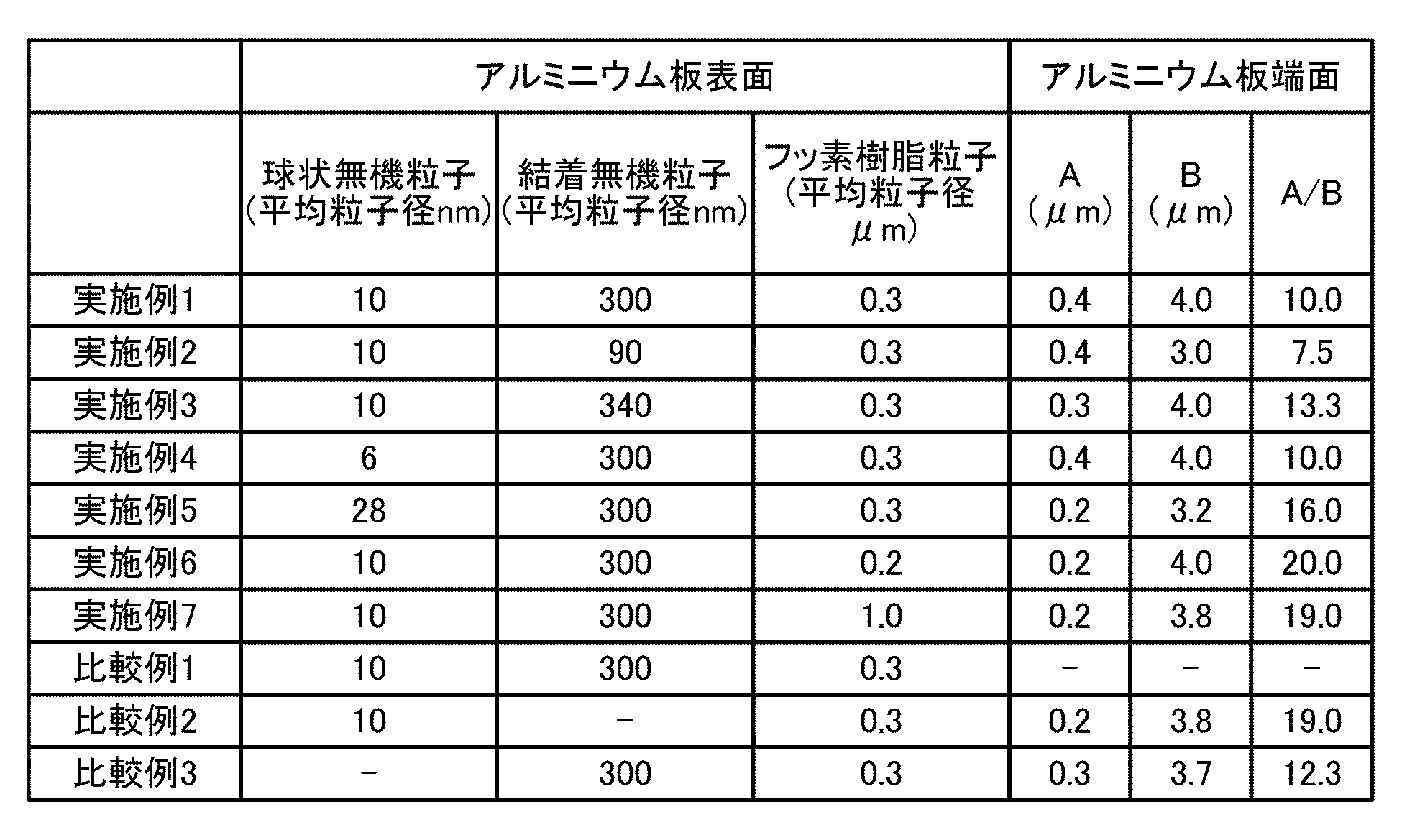
- Example 1 As the hydrophilic composition, the particle size composition shown in "Example 1" of Table 1 was used. As the spherical inorganic particles, JGC Catalysts and Chemicals Co., Ltd. Cataloid (registered trademark) SI-550 was used. After the formation of the hydrophilic layer 9, a fluororesin film 10a was formed on the end face 8b of the aluminum plate at a gas temperature of 150 ° C. and a gas pressure of 0.5 MPa by cold spraying. A / B was measured from the cross-sectional observation. The results are shown in Table 1.
- Example 2 the composition of the average particle size of each particle constituting the hydrophilic composition is different from that of Example 1, and the other parts are the same as in Example 1. That is, as the hydrophilic composition, the particle size composition shown in "Example 2" of Table 1 was used. As the spherical inorganic particles, the same Cataloid (registered trademark) SI-550 manufactured by JGC Catalysts and Chemicals Co., Ltd. as in Example 1 was used. After the formation of the hydrophilic layer 9, a fluororesin film 10a was formed on the end face 8b of the aluminum plate at a gas temperature of 150 ° C. and a gas pressure of 0.5 MPa by cold spraying. A / B was measured from the cross-sectional observation. The results are shown in Table 1.
- Example 3 the composition of the average particle size of each particle constituting the hydrophilic composition and the spherical inorganic particles used in the hydrophilic composition are different from those of Example 1, and the others are the same as in Example 1. .. That is, as the hydrophilic composition, the particle size composition shown in "Example 3" of Table 1 was used. As the spherical inorganic particles, ST-OXS (registered trademark) manufactured by JGC Catalysts and Chemicals Co., Ltd., which is different from Example 1, was used. After the formation of the hydrophilic layer 9, a fluororesin film 10a was formed on the end face 8b of the aluminum plate at a gas temperature of 150 ° C. and a gas pressure of 0.5 MPa by cold spraying. A / B was measured from the cross-sectional observation. The results are shown in Table 1.
- Example 4 the composition of the average particle size of each particle constituting the hydrophilic composition and the spherical inorganic particles used in the hydrophilic composition are different from those of Example 1, and the others are the same as in Example 1. .. That is, as the hydrophilic composition, the particle size composition shown in "Example 4" of Table 1 was used. As the spherical inorganic particles, Cataloid (registered trademark) SI-550 manufactured by Nissan Chemical Industries, Ltd., which is different from Example 1, was used. After the formation of the hydrophilic layer 9, a fluororesin film 10a was formed on the end face 8b of the aluminum plate at a gas temperature of 150 ° C. and a gas pressure of 0.5 MPa by cold spraying. A / B was measured from the cross-sectional observation. The results are shown in Table 1.
- Example 5 the composition of the average particle size of each particle constituting the hydrophilic composition and the spherical inorganic particles used in the hydrophilic composition are different from those of Example 1, and the others are the same as in Example 1. .. That is, as the hydrophilic composition, the particle size composition shown in "Example 5" of Table 1 was used. As the spherical inorganic particles, Cataloid (registered trademark) ST-O40 manufactured by Nissan Chemical Industries, Ltd., which is different from Example 1, was used. After the formation of the hydrophilic layer 9, a fluororesin film 10a was formed on the end face 8b of the aluminum plate at a gas temperature of 150 ° C. and a gas pressure of 0.5 MPa by cold spraying. A / B was measured from the cross-sectional observation. The results are shown in Table 1.
- Example 6 the composition of the average particle size of each particle constituting the hydrophilic composition, the spherical inorganic particles used in the hydrophilic composition, and the gas temperature at the time of forming the fluororesin film 10a are different from those of Example 1. Others are the same as in Example 1. That is, as the hydrophilic composition, the particle size composition shown in "Example 6" of Table 1 was used. As the spherical inorganic particles, Cataloid (registered trademark) ST-O40 manufactured by Nissan Chemical Industries, Ltd., which is different from Example 1, was used. After the formation of the hydrophilic layer 9, a fluororesin film 10a was formed on the end face 8b of the aluminum plate at a gas temperature of 200 ° C. and a gas pressure of 0.5 MPa by cold spraying. A / B was measured from the cross-sectional observation. The results are shown in Table 1.
- Example 7 the composition of the average particle size of each particle constituting the hydrophilic composition, the spherical inorganic particles used in the hydrophilic composition, and the gas temperature at the time of forming the fluororesin film 10a are different from those in Example 1. Others are the same as in Example 1. That is, as the hydrophilic composition, the particle size composition shown in "Example 7" of Table 1 was used. As the spherical inorganic particles, Cataloid (registered trademark) ST-O40 manufactured by Nissan Chemical Industries, Ltd., which is different from Example 1, was used. After the formation of the hydrophilic layer 9, a fluororesin film 10a was formed on the end face 8b of the aluminum plate at a gas temperature of 200 ° C. and a gas pressure of 0.5 MPa by cold spraying. A / B was measured from the cross-sectional observation. The results are shown in Table 1.
- Comparative Example 1 is an example in which the fluororesin film 10a is not formed on the end surface 8b of the aluminum plate.
- the hydrophilic composition the particle size composition shown in "Comparative Example 1" in Table 1 was used.
- the spherical inorganic particles Cataloid (registered trademark) ST-O40 manufactured by Nissan Chemical Industries, Ltd., which is different from Example 1, was used.
- Comparative Example 1 since the fluororesin film 10a was not formed, the A / B was not measured.
- Comparative Example 2 is an example in which the hydrophilic layer 9 does not contain the bound inorganic particles 5.
- the composition of the hydrophilic composition was 0.1% by mass of spherical inorganic particles, 0.05% by mass of bound silica particles, and 0.02% by mass of fluororesin particles, but Comparative Example 2 Is an exception because the hydrophilic layer 9 does not contain the bound inorganic particles 5.
- the composition of the hydrophilic composition of Comparative Example 2 is 0.1% by mass of spherical inorganic particles and 0.02% by mass of fluororesin particles.
- the hydrophilic composition the one having the particle size composition shown in "Comparative Example 2" of Table 1 was used.
- the same Cataloid (registered trademark) SI-550 manufactured by JGC Catalysts and Chemicals Co., Ltd. as in Example 1 was used.
- a fluororesin film 10a was formed on the end face 8b of the aluminum plate at a gas temperature of 150 ° C. and a gas of 0.5 MPa by cold spraying.
- a / B was measured from the cross-sectional observation. The results are shown in Table 1.
- Comparative Example 3 is an example in which the hydrophilic layer 9 does not contain the spherical inorganic particles 6.
- the composition of the hydrophilic composition was 0.1% by mass of spherical inorganic particles, 0.05% by mass of bound silica particles, and 0.02% by mass of fluororesin particles. The exception is because the hydrophilic layer 9 does not contain spherical inorganic particles 6.
- the composition of the hydrophilic composition of Comparative Example 3 is 0.05% by mass of the bound silica particles and 0.02% by mass of the fluororesin particles.
- the hydrophilic composition the one having the particle size composition shown in "Comparative Example 3" of Table 1 was used.
- the initial hydrophilicity was evaluated using aluminum fins left at room temperature (25 ° C.) for 1 hour. Approximately 5 ⁇ L of water droplets are dropped onto the surface of the aluminum fin from the tip of a PTFE (polytetrafluoroethylene) coated needle with an inner diameter of 0.1 mm, and a contact angle meter (CX-150 type manufactured by Kyowa Interface Science Co., Ltd.) is used. , The contact angle (initial water contact angle) was measured. It can be said that the smaller the contact angle, the better the hydrophilicity.
- Initial hydrophilicity was evaluated according to the following criteria. The results are shown in Table 2.
- the contact angle is 10 ° or less.
- the contact angle is 10 ° or more and less than 30 °.
- the contact angle is 30 ° or more and less than 50 °.
- the contact angle is 50 ° or more and less than 70 °.
- the contact angle is 70 ° or more.
- the sustained hydrophilicity was evaluated by conducting an accelerated test simulating air conditioning.
- the aluminum fins were left in an ion-exchanged running water environment for 7 hours and then exposed in a constant temperature bath at 80 ° C. for 17 hours. With this as one cycle, the contact angle was measured after 14 cycles. Persistent hydrophilicity was evaluated according to the following criteria. The results are shown in Table 2.
- the contact angle is 10 ° or less.
- the contact angle is 10 ° or more and less than 30 °.
- the contact angle is 30 ° or more and less than 50 °.
- the contact angle is 50 ° or more and less than 70 °.
- the contact angle is 70 ° or more.
- the dust adhesion suppression performance was evaluated by evaluating the amount of mixed dust of sand dust, which is a hydrophilic fouling substance, and carbon black dust, which is a hydrophobic fouling substance. Under the conditions of temperature 25 ° C and humidity 50%, JIS 11 type Kanto loam dust and JIS 12 type carbon black dust are sprayed on the aluminum plate with air, and then the surface of the aluminum plate is covered with mending tape (manufactured by 3M Japan Ltd.). Remove deposits. Then, the absorbance (wavelength 550 nm) of the surface of the aluminum plate from which the deposits were removed was measured with a spectrophotometer (manufactured by Shimadzu Corporation; UV-3100PC) and evaluated according to the following criteria. The smaller the absorbance, the higher the dust adhesion suppression performance. The results are shown in Table 2.
- Absorbance is less than 0.1.
- 3 Absorbance of 0.2 or more and less than 0.3.
- 4 Absorbance of 0.3 or more and less than 0.4.
- 5 Absorbance of 0.4 or more.
- Adhesion area is less than 10%.
- Adhesion area is 10% or more and less than 30%.
- Adhesion area is 30% or more and less than 50%.
- Adhesion area is 50% or more and less than 70%.
- Adhesion area is 70% or more.
- the aluminum fins of Examples 1 to 7 have an evaluation result of initial hydrophilicity and sustained hydrophilicity of 3 or less, and have initial water repellency and water repellency based on the contact angle. Good sustainability. Further, the aluminum fins having the antifouling property of Examples 1 to 7 have an evaluation result of 3 or less in the dust adhesion suppressing performance, and the dust adhesion suppressing performance based on the absorbance is also high. Further, the aluminum fins having the antifouling property of Examples 1 to 7 had an evaluation result of 3 or less in the oil droplet dust adhesion suppressing performance, and could maintain a high oil droplet dust adhesion suppressing performance based on the adhesion area. .. Among them, the aluminum fin having antifouling property of Example 1 had good initial hydrophilicity, continuous hydrophilicity, dust adhesion suppressing performance, and oil droplet dust adhesion suppressing performance.
- the aluminum fin of Comparative Example 1 does not form the water-repellent layer 10 on the end surface 8b of the aluminum plate, the oil droplet dust adhesion suppressing performance is significantly deteriorated. Further, in the aluminum fin of Comparative Example 2, since the hydrophilic layer 9 does not contain the bound inorganic particles 5, the initial hydrophilicity is deteriorated. Further, in the aluminum fin of Comparative Example 3, since the hydrophilic layer 9 does not contain the spherical inorganic particles 6, the sustained hydrophilicity is deteriorated.
- the aluminum plate surface 8a along the air flow direction in the aluminum plate 8 constituting the aluminum fin 3 and the aluminum plate are perpendicular to the air flow direction.
- the configuration shown in the above-described embodiment shows an example of the contents of the present disclosure, can be combined with another known technique, and is one of the configurations as long as it does not deviate from the gist of the present disclosure. It is also possible to omit or change the part.
Landscapes
- Engineering & Computer Science (AREA)
- Physics & Mathematics (AREA)
- Thermal Sciences (AREA)
- Mechanical Engineering (AREA)
- General Engineering & Computer Science (AREA)
- Laminated Bodies (AREA)
Abstract
熱交換器のアルミフィンは、アルミニウム板と、アルミニウム板において空気の流れ方向に沿うアルミニウム板表面およびアルミニウム板において空気の流れ方向に垂直な面であるアルミニウム板端面に形成された耐食樹脂層と、アルミニウム板表面の耐食樹脂層の表面に形成された親水層と、アルミニウム板端面の耐食樹脂層の表面に形成された撥水層と、を備える。親水層は、大径無機粒子の表面に大径無機粒子よりも小径の小径無機粒子が結着した構成の結着無機粒子と球状無機粒子とを有する膜にフッ素樹脂粒子が点在した構成を有する。撥水層は、結着無機粒子と球状無機粒子とを有する膜の表面に凹凸構造を有するフッ素樹脂皮膜が形成された構成を有する。
Description
本開示は、アルミフィンを有する熱交換器および熱交換器の製造方法に関するものである。
各種の製品表面は、その環境からの様々な汚染物質に曝されることで、汚く見えたり、衛生的に問題を生じたり、腐食等により性能劣化が引き起こされたりする。中でも、空調機器における熱交換器は、その機能上、環境からの汚染の影響を非常に受けやすいものであり、汚染によって各種の不都合を生じやすい。
熱交換器は、冷媒が通るパイプに多数枚のフィン(例えば、アルミニウム板)が取り付けられた構造を有しており、表面積が大きいフィンによって熱交換効率を高めている。このフィンの表面には、冷暖房時に凝結水が付着し易く、フィン間が凝結水によって封鎖される現象(以下、「ブリッジ現象」という。)によって通風抵抗が増大して熱交換効率が低下することがある。特に、ブリッジ現象は、粉塵などの汚れがフィンの表面に付着することによって起こり易くなる。このため、従来、防汚性に優れた有機系または無機系の親水性被膜をフィンの表面に形成することによってブリッジ現象を防止している。ここで、本明細書において「防汚性」とは、汚れが付着し難い性能、および付着した汚れが除去され易い性能を意味する。
熱交換器のフィンに防汚性を付与する技術については、これまでいくつかの方法が開示されている。特許文献1では、「アルミニウムからなる基板と、前記基板上に形成され、表面に露出した樹脂塗膜と、を有し、前記樹脂塗膜は、けん化度が95.0~99.8%であるポリビニルアルコール(A)と、酸価が20~100mgKOH/gであるアクリルアミド系ポリマー(B)と、数平均分子量が6000~20000であるポリエチレングリコール(C)と、体積基準における平均粒子径が100~300nmであるフッ素樹脂粒子(D)と、を含有し、前記樹脂塗膜の質量を100質量部とした場合に、前記ポリエチレングリコール(C)の含有量は1.0~13質量部であり、かつ、前記フッ素樹脂粒子(D)の含有量は2.0~5.0質量部であり、前記ポリビニルアルコール(A)の含有量は、質量比において、前記アクリルアミド系ポリマー(B)の含有量の0.3~0.6倍である」、プレコートフィン材が提案されている。
特許文献1では、フィンに防汚性および親水性を付与できるとされているが、熱交換器においては、フィンの防汚性と長期に渡る親水性の持続が課題とされており、更なる改良が求められている。
本開示は、上記のような問題を解決するためになされたものであり、防汚性および持続親水性を有する熱交換器および熱交換器の製造方法を提供することを目的とする。
本開示に係る熱交換器は、空気の流れ方向に沿って配置されるアルミフィンを有する熱交換器であって、アルミフィンは、アルミニウム板と、アルミニウム板において空気の流れ方向に沿うアルミニウム板表面およびアルミニウム板において空気の流れ方向に垂直な面であるアルミニウム板端面に形成された耐食樹脂層と、アルミニウム板表面の耐食樹脂層の表面に形成された親水層と、アルミニウム板端面の耐食樹脂層の表面に形成された撥水層と、を備え、親水層は、大径無機粒子の表面に大径無機粒子よりも小径の小径無機粒子が結着した構成の結着無機粒子と球状無機粒子とを有する膜にフッ素樹脂粒子が点在した構成を有し、撥水層は、結着無機粒子と球状無機粒子とを有する膜の表面に凹凸構造を有するフッ素樹脂皮膜が形成された構成を有するものである。
本開示に係る熱交換器の製造方法は、空気の流れ方向に沿って配置されるアルミフィンを有する熱交換器の製造方法であって、アルミフィンを構成するアルミニウム板において空気の流れ方向に沿うアルミニウム板表面およびアルミニウム板において空気の流れ方向に垂直な面であるアルミニウム板端面に耐食樹脂層を形成する第1工程と、耐食樹脂層の表面に、大径無機粒子の表面に大径無機粒子よりも小径の小径無機粒子が結着した構成の結着無機粒子と球状無機粒子とフッ素樹脂粒子とを有する親水組成物を付与して親水層を形成する第2工程と、親水層が形成されたアルミニウム板端面にフッ素樹脂粒子粉末を吹き付けてフッ素樹脂皮膜を形成し、撥水層を形成する第3工程と、を有するものである。
本開示によれば、親水層が、結着無機粒子と球状無機粒子とを有する膜にフッ素樹脂粒子が点在した構成を有することで、熱交換器は、粉塵に対して優れた防汚性を有する。また、親水層が球状無機粒子を有するため、熱交換器は持続親水性を有する。さらに、撥水層が結着無機粒子と球状無機粒子とを有する膜の表面に凹凸構造を有するフッ素樹脂皮膜が形成された構成を有するため、熱交換器は、防汚性および持続親水性を有する。
以下、防汚性を有する熱交換器、および熱交換器の製造方法について図面等を参照しながら説明する。なお、図1を含む以下の図面では、各構成部材の相対的な寸法の関係および形状等が実際のものとは異なる場合がある。また、以下の図面において、同一の符号を付したものは、同一またはこれに相当するものであり、このことは明細書の全文において共通することとする。そして、明細書全文に表わされている構成要素の形態は、あくまでも例示であって、明細書に記載された形態に限定するものではない。
実施の形態1.
図1は、実施の形態1に係る熱交換器の概略構成図である。図2は、実施の形態1に係る熱交換器のアルミフィンの模式図である。図3は、実施の形態1に係る熱交換器のアルミフィンの表面の模式図である。図4は、実施の形態1に係る熱交換器のアルミフィンの端面の模式図である。
図1に示すように、本実施の形態1に係る熱交換器1は、冷媒管2と、防汚性を有するアルミフィン3とを備える。アルミフィン3は、図2に示すように、アルミニウム板8と、耐食樹脂層4と、親水層9と、撥水層10と、を備える。以下では、アルミフィン3のうち、熱交換器1を通過する空気の流れに沿う方向の表面をアルミフィン表面3a、熱交換器1を通過する空気の流れに垂直な面をアルミフィン端面3bと定義する。アルミニウム板8についても同様に、アルミニウム板表面8aとアルミニウム板端面8bとを定義する。
図1は、実施の形態1に係る熱交換器の概略構成図である。図2は、実施の形態1に係る熱交換器のアルミフィンの模式図である。図3は、実施の形態1に係る熱交換器のアルミフィンの表面の模式図である。図4は、実施の形態1に係る熱交換器のアルミフィンの端面の模式図である。
図1に示すように、本実施の形態1に係る熱交換器1は、冷媒管2と、防汚性を有するアルミフィン3とを備える。アルミフィン3は、図2に示すように、アルミニウム板8と、耐食樹脂層4と、親水層9と、撥水層10と、を備える。以下では、アルミフィン3のうち、熱交換器1を通過する空気の流れに沿う方向の表面をアルミフィン表面3a、熱交換器1を通過する空気の流れに垂直な面をアルミフィン端面3bと定義する。アルミニウム板8についても同様に、アルミニウム板表面8aとアルミニウム板端面8bとを定義する。
本実施の形態1に係るアルミフィン3は、アルミニウム板表面8aに耐食樹脂層4が形成され、耐食樹脂層4の表面に親水層9が形成された構成を有する。また、本実施の形態1に係るアルミフィン3は、アルミニウム板端面8bに耐食樹脂層4が形成され、耐食樹脂層4の表面に撥水層10が形成された構成を有する。なお、アルミフィン3は、アルミニウム板8と耐食樹脂層4との間に下地処理層をさらに備えていてもよい。
アルミニウム板表面8aの各層は、アルミニウム板8の片側表面のみに形成されていてもよいし、両側表面に形成されていてもよい。アルミフィン端面3bの各層についても同様であり、アルミニウム板8の片側端面のみに形成されていてもよいし、両側端面に形成されていてもよい。なお、撥水層10がアルミニウム板8の片側端面のみに形成される場合は、空気の流れの上流側の端面に形成される。すなわち、撥水層10は、アルミニウム板8において2面あるアルミニウム板端面8bのうち、空気の流れの上流側のアルミニウム板端面に少なくとも形成される。
アルミニウム板8は、純アルミニウムまたはアルミニウム合金からなる。そして、アルミニウム板8としては、熱伝導性および加工性の観点から、JIS H 4000:2014に規定されている1000系のアルミニウムを好適に用いることができる。より具体的には、アルミニウム板8として合金番号1050、1070、1200のアルミニウムが好ましく用いられる。ただし、アルミニウム板8として適宜、2000系ないし9000系のアルミニウム合金を用いてもよい。アルミニウム板8の板厚は、熱交換器1の用途および仕様などに応じて適宜決定すればよい。具体的には、アルミニウム板8の板厚は、フィンへの加工性、フィンの強度および熱伝導性などを適切に確保する観点から0.08mm以上、0.3mm以下とするのが好ましい。
アルミニウム板8の板厚が0.08mm以上であれば、一般的なフィン材に求められる程度の強度を確保することができる。一方、アルミニウム板8の板厚が0.3mm以下であれば、フィンへの加工性を確保することができる。
親水層9は、親水性を有する層であって、防汚性を有する膜である。親水層9は、結着無機粒子5と球状無機粒子6とフッ素樹脂粒子7とを有する。親水層9が結着無機粒子5を有することにより、冷房時にアルミフィン3上に生成する結露水との接触面積を大きくすることが可能となる。接触面積が大きくなるのは、親水層9の表面構造が、結着無機粒子5自体の存在による大きな凹凸構造と、該結着無機粒子5の表面の微細凹凸と、の二つのフラクタル様構造をとることによる。このように親水層9の表面構造がフラクタル様構造をとることにより、親水層9が形成されたアルミフィン表面3aは、高い親水性を有し、アルミフィン3表面に生成する結露水を排水できる。また、球状無機粒子6は、結着無機粒子5と耐食樹脂層4との密着性を高める効果および長期に渡って親水性を持続する効果がある。フッ素樹脂粒子7は、親水性粉塵の付着抑制効果がある。
親水層9は、具体的には図3に示すように結着無機粒子5と球状無機粒子6とを有する膜中に、フッ素樹脂粒子7が点在した構成を有する。結着無機粒子5と球状無機粒子6とを有する膜は、フッ素樹脂粒子7で分断されることなく連続しており、結着無機粒子5と球状無機粒子6とを有する膜の面積は、最表面に露出するフッ素樹脂粒子7の面積に比べ十分に大きい。結着無機粒子5と球状無機粒子6とを有する膜が連続していることにより、親水層9は、親水層表面に水滴が付着した場合等において、水が非常に拡がりやすい特性を有する。一方、親水層9においてフッ素樹脂粒子7同士が繋がったり、近接して配置されたり、面積が大きかったり、不均一に分布し局所的に多数が配置されたりした状態であると、親水層表面での水の拡がりが阻害される。
実施の形態1の親水層9は、水が拡がりやすいという高い親水性の状態を維持したまま、汚染粒子の付着に関連する微小な領域で見れば、フッ素樹脂粒子7が分散して最表面に点在する構成を有することで、親水性部分と疎水性部分とが共存した状態を有する。このような構成の親水層9を有するアルミフィン表面3aは、吸湿時および乾燥時の水分の移動が容易であり、アルミフィン表面3aに付着した親水性粒子および疎水性粒子を浮き上がらせて遊離させたり、固着し難くしたりする効果がある。つまり、親水層9を有するアルミフィン表面3aは、優れた防汚性を有する。また、親水層9は、水が流れやすく拡がりやすい特性を有するため、以下の効果を有する。すなわち、結露時、降雨時および洗浄時等、アルミフィン表面3aに水が流れる状況においては、アルミフィン表面3aに付着した物質がアルミフィン表面3aに流れる水と共に流れて非常に除去されやすいという効果もある。以上より、親水層9を有するアルミフィン表面3aは、優れた防汚性を有すると共に、親水層9が球状無機粒子6を有することで、親水層9を有するアルミフィン表面3aは持続親水性を有するものとなる。
撥水層10は、撥油撥水性を有する層であって、防汚性を有する膜である。撥水層10は、結着無機粒子5と球状無機粒子6とを有する膜の表面に、凹凸構造を有するフッ素樹脂皮膜10aが形成された構成を有する。フッ素樹脂皮膜10aは、フッ素樹脂粒子粉末による防汚皮膜である。アルミフィン端面3bは、撥水層10の撥油撥水性により、油煙などの付着を抑制できる。また、フッ素樹脂皮膜10aが凹凸構造を有することで、撥水層10の表面と粉塵などの粒子物質との接触面積が小さくなるため、アルミフィン端面3bは、粉塵の付着も抑制することができる。また、撥水層10は、結着無機粒子5を有するため、水との接触面積を大きくすることが可能な微小凹凸構造を有する。これにより、アルミフィン端面3bは、高い親水性を有し、アルミフィン端面3bに生成する結露水を排水できる。
以下、耐食樹脂層4、親水層9および撥水層10についてさらに詳細に説明する。
[耐食樹脂層]
耐食樹脂層4は、アルミニウム板8の腐食を抑制するための樹脂成分で構成される層である。耐食樹脂層4は、アクリル系樹脂およびエポキシ系樹脂の両方を含んで構成されていてもよく、実質的に一方のみを含んで構成されていてもよい。すなわち、耐食樹脂層4は、アクリル系樹脂またはエポキシ系樹脂からなっていてもよい。耐食樹脂層4中の樹脂の含有率は、例えば90質量%以上または95質量%以上である。また耐食樹脂層4は、必要に応じて、アクリル系樹脂およびエポキシ系樹脂以外のその他の樹脂を含んでいてもよい。
耐食樹脂層4は、アルミニウム板8の腐食を抑制するための樹脂成分で構成される層である。耐食樹脂層4は、アクリル系樹脂およびエポキシ系樹脂の両方を含んで構成されていてもよく、実質的に一方のみを含んで構成されていてもよい。すなわち、耐食樹脂層4は、アクリル系樹脂またはエポキシ系樹脂からなっていてもよい。耐食樹脂層4中の樹脂の含有率は、例えば90質量%以上または95質量%以上である。また耐食樹脂層4は、必要に応じて、アクリル系樹脂およびエポキシ系樹脂以外のその他の樹脂を含んでいてもよい。
アクリル系樹脂は、(メタ)アクリル酸、(メタ)アクリル酸エステル等に由来する構造単位を有する重合体である。アクリル系樹脂は架橋構造を含んでいてもよく、架橋構造は架橋性の官能基を有する単量体に由来して形成される。架橋性の官能基としては、例えば、イソシアネート基、オキサゾリン基、メチレン基、カルボジイミド基またはアジリジン基などが挙げられる。また、架橋構造はメラミン等に由来して形成されていてもよい。アクリル系樹脂を含む樹脂組成物としては、金属付着性を有する樹脂層を形成可能な市販品から適宜選択すればよい。市販品としては、例えば、DIC株式会社製のボンコート(登録商標)シリーズまたは日本パーカライジング株式会社製のTOPシリーズ等を挙げることができる。
エポキシ系樹脂は、分子内にエポキシ基を有する単量体に由来する構造単位を含んで構成される重合体である。エポキシ系樹脂は架橋構造を含んでいてもよく、上述した架橋構造は架橋性の官能基を有する単量体に由来して形成される。エポキシ系樹脂を含む樹脂組成物としては、金属付着性を有する樹脂層を形成可能な市販品から適宜選択すればよい。市販品としては、例えば、DIC株式会社製のEPICRON(登録商標)等を挙げることができる。耐食樹脂層4は、エポキシ系樹脂を1種単独で含んでいてもよく、2種以上を組合せて含んでいてもよい。その他の樹脂としては、例えば、ポリエステル系樹脂、エチレンアクリル系樹脂およびウレタン系樹脂等を挙げることができる。
耐食樹脂層4の皮膜量は、0.05mg/dm2以上であり、0.08mg/dm2以上、さらに0.10mg/dm2以上が好ましい。耐食樹脂層4の皮膜量が0.05mg/dm2以上であることによって、優れた防汚性を発揮することができる。また、耐食樹脂層4の皮膜量は、8.00mg/dm2以下であり、6.00mg/dm2以下、さらに5.00mg/dm2以下が好ましい。耐食樹脂層4の皮膜量が8.00mg/dm2を超えると、親水性が低下し、高いレベルの親水性を確保できなくなる。
耐食樹脂層4の皮膜量は、耐食樹脂層4の成膜に用いる塗料組成物の濃度、および、成膜に用いるバーコーターNo.の選択などによって調整することができる。また、耐食樹脂層4の皮膜量は、蛍光X線、赤外膜厚計または皮膜剥離による質量測定などで測定することが可能である。なお、親水層9およびフッ素樹脂皮膜10aの皮膜量の調整方法ならびに測定方法は、前記した耐食樹脂層4の場合と同様である。
[親水層]
親水層9は、上述したように結着無機粒子5と球状無機粒子6とフッ素樹脂粒子7とを有する。球状無機粒子6は、SiO2、Al2O3、Sb2O5、ZrO2、TiO2、Fe2O3、CeO2、AgO、CuO、Cu2O、ZnOおよびこれらの複合酸化物または混合物から選ばれる少なくとも1種で構成される。球状無機粒子6は、平均粒径が5nm以上、30nm以下であることが好ましい。球状無機粒子6は、親水性のシリカ粒子またはチタン粒子が好ましい。シリカが球状粒子であることにより、さらに、親水性の効果を高めることができる。
親水層9は、上述したように結着無機粒子5と球状無機粒子6とフッ素樹脂粒子7とを有する。球状無機粒子6は、SiO2、Al2O3、Sb2O5、ZrO2、TiO2、Fe2O3、CeO2、AgO、CuO、Cu2O、ZnOおよびこれらの複合酸化物または混合物から選ばれる少なくとも1種で構成される。球状無機粒子6は、平均粒径が5nm以上、30nm以下であることが好ましい。球状無機粒子6は、親水性のシリカ粒子またはチタン粒子が好ましい。シリカが球状粒子であることにより、さらに、親水性の効果を高めることができる。
シリカ粒子の平均粒径は、光散乱法により測定した場合、平均粒径が5nm以上、30nm程度以下であることが好ましい。親水層9の製造方法の詳細は後述するが、親水層9は、液状のコーティング溶液である親水組成物をアルミニウム板8に塗布して乾燥させて形成される。平均粒径が5nm以上、30nm以下の範囲内にあるシリカ粒子は、1つのシリカ粒子について、シリカ粒子重量のおおよそ15~30%の重量に相当する表面部分が、親水組成物において、半ば水に溶解した状態となっている。しかし、平均粒径が5nm未満のシリカ粒子は、親水組成物において、半ば水に溶解した状態のシリカ成分の割合が高くなりすぎて、シリカ粒子同士が凝集してしまう。シリカ粒子同士が凝集すると、得られる親水層9の透明性が低下する。
一方、平均粒径が5nm以上、30nm以下のシリカ粒子であれば、親水層9により反射する光の散乱が小さくなるため、親水層9の透明性が向上する。親水層9の透明性が向上することで、アルミニウム板8の色調および風合いの変化が抑えられ、アルミニウム板8の色調および風合いを損なわないようにできる。また、球状無機粒子6として、平均粒径が5nm以上、30nm以下の球状シリカ粒子を用いることで、得られる親水層9は、シリカ成分が緻密ではありながらシリカ粒子間に微細な空隙を有するものとなる。シリカ成分の緻密さにより、親水層9の膜厚は薄くできる。また、シリカ粒子間に形成される空隙により、汚染の原因となる粒子とシリカ粒子との分子間力つまり付着力が小さくなるため、親水層9は、汚染の原因となる粒子を固着させにくくする効果がある。
結着無機粒子5は、親水性を有する。結着無機粒子5は、シリカ粒子もしくはチタン粒子で構成される。結着無機粒子5は、図3に示すように基体となる大径無機粒子5aの表面に、大径無機粒子5aよりも小径の小径無機粒子5bが結着した構成を有する。結着無機粒子5は、大径無機粒子5a自体の存在による大きな凹凸構造と、この大径無機粒子5aの表面の微細な小径無機粒子5bによる微細凹凸と、の二つのフラクタル様構造をとることにより、さらに高い親水性を有している。特に結着無機粒子5は、大径無機粒子5a上に粒子径の揃った小径無機粒子5bが配置されているので、上記のフラクタル様構造を取り易い。そのため、結着無機粒子5は、他の無機粒子に比べ、より親水性を発現しやすいと考えられる。
結着無機粒子5の表面の親水性は、粒子表面の-OH基の数が多くなると高くなり、さらに-OH基の数以外に、結着無機粒子5の表面にナノサイズの微細凹凸を有することによってさらに高くなる。また、このようなマトリックス成分を使用するときに、無機粒子をクラスター状にして皮膜を形成することが知られているが、この方法では、皮膜の密着性が不十分であったり、透明皮膜を得たいときに透明性の低い膜になったりする場合がある。
大径無機粒子5aの粒子径は、80nm以上、300nm以下であることが好ましい。大径無機粒子5aの粒子径が80nm未満であると、排水性効果が得られないため好ましくない。また、大径無機粒子5aの粒子径が300nm超であると、基材との密着性が低下したり、白濁したりするため好ましくない。小径無機粒子5bの粒子径は、5nm以上、20nm以下であることが好ましい。小径無機粒子5bの粒子径が5nm未満であると、製造上困難であるため好ましくない。また、小径無機粒子5bの粒子径が20nm超であると、基材との密着性が低下するため好ましくない。結着無機粒子5の平均粒子径は、80nm以上、350nm以下である。
フッ素樹脂粒子7は、フッ素樹脂粒子7の平均粒子径が0.1μm以上、1.0μm以下であるのが好ましく、0.2μm以上、0.9μm以下であるのがより好ましい。フッ素樹脂粒子7には、このように好ましい平均粒子径があるものの、フッ素樹脂粒子7の平均粒子径は特に限定されない。フッ素樹脂粒子7の粒子径は、走査電子顕微鏡(SEM)および電子線マイクロアナライザ(EPMA)によって測定することができる。
以上説明したように、実施の形態1の熱交換器1は、空気の流れ方向に沿って配置されるアルミフィン3を有する熱交換器である。アルミフィン3は、アルミニウム板8と、アルミニウム板8において空気の流れ方向に沿うアルミニウム板表面8aおよびアルミニウム板において空気の流れ方向に垂直な面であるアルミニウム板端面8bに形成された耐食樹脂層4とを備える。アルミフィン3はさらに、アルミニウム板表面8aの耐食樹脂層4の表面に形成された親水層9と、アルミニウム板端面8bの耐食樹脂層4の表面に形成された撥水層10と、を備える。親水層9は、大径無機粒子5aの表面に大径無機粒子5aよりも小径の小径無機粒子5bが結着した構成の結着無機粒子5と球状無機粒子6とを有する膜にフッ素樹脂粒子7が点在した構成を有する。撥水層10は、結着無機粒子5と球状無機粒子6とを有する膜の表面に凹凸構造を有するフッ素樹脂皮膜10aが形成された構成を有する。
このように親水層9が結着無機粒子5と球状無機粒子6とを有する膜にフッ素樹脂粒子7が点在した構成を有することで、親水層9は、親水性部分と疎水性部分とが共存した状態を有する。このため、親水層9を有するアルミフィン3を備えた熱交換器1は、粉塵に対して優れた防汚性を有する。また、親水層9が球状無機粒子6を有するため、親水層9を有するアルミフィン3を備えた熱交換器1は持続親水性を有する。さらに、撥水層10が結着無機粒子5と球状無機粒子6とを有する膜の表面に凹凸構造を有するフッ素樹脂皮膜10aが形成された構成を有するため、撥水層10を有するアルミフィン3を備えた熱交換器1は、持続親水性を有すると共に、油滴および粉塵に対して優れた防汚性を有する。
大径無機粒子5aの粒子径は、80nm以上、300nm以下であり、小径無機粒子5bの粒子径は、5nm以上、20nm以下であり、結着無機粒子5の平均粒子径は80nm以上、350nm以下である。また、球状無機粒子6は、平均粒径が5nm以上、30nm以下である。また、フッ素樹脂粒子7は、平均粒径が0.1μm以上、1.0μm以下である。
これにより、防汚性および持続親水性を有する熱交換器1を得ることができる。
実施の形態2.
実施の形態2は、アルミフィン3の製造工程に関するものである。
実施の形態2は、アルミフィン3の製造工程に関するものである。
熱交換器用のアルミフィン3の製造方法は、アルミニウム板8に耐食樹脂組成物を付与して耐食樹脂層4を形成する第1工程と、耐食樹脂層4の表面に親水層9を形成する第2工程と、アルミニウム板端面8bに撥水層10を形成する第3工程と、を含む。アルミニウム板8には、アルミニウム単体からなる基板またはアルミニウム合金からなる基板が用いられる。
第1工程前に行う下地処理工程では、アルミニウム板8の片面または両面、好ましくは両面に下地処理層を形成する。下地処理層は公知の手法によって形成される。無機酸化物を含む下地処理層は、例えば、リン酸クロメート処理、リン酸ジルコニウム処理、クロム酸クロメート処理、リン酸亜鉛処理およびリン酸チタン酸処理等からなる群から選択される少なくとも1種を行うことによって形成される。また、有機-無機複合化合物を含む下地処理層は、例えば、塗布型クロメート処理および塗布型ジルコニウム処理等からなる群から選択される少なくとも1種を行うことによって形成される。
第1工程では、アルミニウム板表面8aおよびアルミニウム板端面8bに耐食樹脂組成物を付与して耐食樹脂層4を形成する。耐食樹脂層4が形成されるアルミニウム板表面8aは、片側表面でもよいし、両側表面でもよい。同様に、耐食樹脂層4が形成されるアルミニウム板端面8bも、片側端面でもよいし、両側端面でもよい。第1工程に用いられるアルミニウム板8は、上記下地処理工程が行われたものでもよいし、行われていないものでもよい。
耐食樹脂組成物は、アクリル系樹脂およびエポキシ系樹脂からなる群から選択される少なくとも1種を含み、例えば、媒体として水を含む水系樹脂組成物である。耐食樹脂組成物は、アクリル系樹脂またはエポキシ系樹脂を含む市販の樹脂組成物から適宜選択すればよい。耐食樹脂組成物のアルミニウム板8への付与方法としては、例えばバーコーター、ロールコーターおよびフローコーター等の通常用いられる塗布装置を用いる方法が挙げられる。また、組成物の付与量は目的とする耐食樹脂層4の厚み等に応じて適宜選択すればよい。
第2工程では、第1工程後のアルミニウム板8の耐食樹脂層4上に親水組成物を付与して親水層9を形成する。親水組成物は、結着無機粒子5と球状無機粒子6とフッ素樹脂粒子7とを含有し、例えば、媒体として水を含む水系組成物である。親水組成物の耐食樹脂層4上への付与方法としては、例えば、バーコーター、ロールコーターおよびフローコーター等の通常用いられる塗布装置を用いる方法が挙げられる。親水組成物における結着無機粒子5および球状無機粒子6のそれぞれの含有量は、0.01質量%以上、5質量%以下が好ましく、0.02質量%以上、4質量%以下がさらに好ましい。含有量が少なすぎると、無機粒子が、まばらになって親水層9の基体を形成できず十分な親水性が得られない。含有量が5質量%を超えると、親水層9の基体が厚くなりすぎて、クラックが生じやすくなるため好ましくない。また、含有量が少なすぎると、着臭も発生しやすくなるため、好ましくない。
親水組成物における球状無機粒子6と結着無機粒子5との質量比は、50:50~95:5としており、さらに好ましくは80:20とする。このような範囲の重量比であれば、得られる親水層9は、初期の高い親水性と長期に渡る持続親水性を得ることができる。
親水組成物におけるフッ素樹脂粒子7の含有量は、親水組成物に対して0.01質量%以上、0.30質量%以下が好ましい。フッ素樹脂粒子7の含有量が0.01質量%以上であることによって、優れた防汚性を発揮することができる。フッ素樹脂粒子7の含有量が0.30質量%を超えると、フッ素樹脂粒子7に基づく疎水性が向上し過ぎてしまい、親水性が低下してしまう。
上記記載の方法により、アルミニウム板表面8aに防汚性を有する膜である親水層9を形成することができる。また、上記記載の方法により、アルミニウム板端面8bにも一旦、親水層9が形成されるが、以下に詳述する第3工程を行うことで、親水層9が撥水層10に変わり、アルミニウム板端面8bに撥水層10が形成される。
第3工程では、親水層9が形成されたアルミニウム板端面8bにフッ素樹脂粒子粉末を吹き付けることにより、アルミニウム板端面8bにフッ素樹脂皮膜10aを形成し、撥水層10を形成する。アルミニウム板端面8bに形成された親水層9にフッ素樹脂粒子粉末を吹き付けることで、吹き付けられたフッ素樹脂粒子粉末と、親水層9の表面に点在していたフッ素樹脂粒子7とがなじみ、フッ素樹脂皮膜10aとして形成される。具体的には、結着無機粒子5および球状無機粒子6による凹凸構造の表面にフッ素樹脂皮膜10aが形成された構造の撥水層10が、アルミニウム板端面8b上に形成される。このように、第3工程を行うことでフッ素樹脂粒子7が粒子状ではなくフッ素樹脂皮膜10aとなるため、第2工程後にアルミニウム板端面8bにフッ素樹脂粒子7が残留して点在していても、最終的に得られる撥水層10の撥水性に影響はない。
フッ素樹脂粒子粉末をアルミニウム板端面8bに吹き付ける際には、コールドスプレー法による吹き付けを行うコールドスプレー装置が用いられる。コールドスプレー法は、コールドスプレー用粉末を溶融温度以下の固相状態で基材へ衝突させ成膜する技術である。ここでは、コールドスプレー用粉末にフッ素樹脂粒子粉末が用いられる。フッ素樹脂粒子粉末には、エムテック化学株式会社製PTFEパウダーHMP-40、HMP-50およびHMP-70およびテクノケミカル株式会社製マイクロディスパースなどが用いられる。コールドスプレー法による皮膜形成は、市販の低圧コールドスプレー装置、例えばプラズマ技研工業株式会社製のPCS-1000などを用いて行うことができる。コールドスプレー法は溶射の一種と分類されるが、熱エネルギーにより材料粒子を溶かして吹き付ける従来の溶射法と比較すると、材料粒子を溶融させず、主に運動エネルギーで皮膜を形成するという点で、大きな違いがある。
材料粒子が基材に付着して堆積するには、吹き付け速度として、臨界速度(Critical velocity:Vcr)と呼ばれる値超の速度が必要である。吹き付け速度がVcr以下では、基材に皮膜が形成されず、基材がエロージョン摩耗し、基材に小さなクレーター状のくぼみが形成される。一方、吹き付け速度がVcrを超えると、材料粒子が基材に衝突する際、材料粒子と基材との界面付近で塑性変形が生じる。この衝突および変形により、界面付近では温度が上昇し、外に向かって膜状のジェットが押し出される。これらの過程で粒子-基材、粒子-皮膜界面で固相接合が生じ、皮膜が形成されるとされている。吹き付け速度がVcrを超える場合、高分子の粒子の熱変質を抑えることもできる。
本フッ素樹脂皮膜10aの形成は、前記記載のコールドスプレー装置に限定されるものではなく、記載の構造を有する皮膜が形成できれば他の装置を用いても良い。しかし、フッ素樹脂皮膜10aは、低圧型のコールドスプレー装置を用いて基材にコールドスプレー用粉末を吹き付けて形成することが好ましい。低圧型のコールドスプレー装置を用いることで、アルミニウム板端面のみに選択的に皮膜化できることが利点として挙げられる。また、溶剤または水に分散されたフッ素樹脂と比較して、フッ素樹脂粉末を用いることで、基材と強固に密着した皮膜を形成できる。高圧型では、基材に衝突する際の衝撃が強くなり粉末粒子が跳ね返るため、良好な皮膜を形成できない。
図5は、実施の形態2に係る熱交換器の製造に用いるコールドスプレー装置を示す概略図である。
図5に示すコールドスプレー装置17は、ガス供給口11と、ヒーター12と、粉末供給部13と、ノズル14と、を有している。コールドスプレー装置17は、ガス供給口11から供給される加圧されたキャリアガスをヒーター12で加熱し、粉末供給部13から供給されるコールドスプレー用粉末15と共に、ノズル14の先端から基材16に向けて噴射し、基材16上に皮膜16aを形成する。低圧型のコールドスプレー装置17は、キャリアガスの圧力が1Mpa以下であるものを指す。
図5に示すコールドスプレー装置17は、ガス供給口11と、ヒーター12と、粉末供給部13と、ノズル14と、を有している。コールドスプレー装置17は、ガス供給口11から供給される加圧されたキャリアガスをヒーター12で加熱し、粉末供給部13から供給されるコールドスプレー用粉末15と共に、ノズル14の先端から基材16に向けて噴射し、基材16上に皮膜16aを形成する。低圧型のコールドスプレー装置17は、キャリアガスの圧力が1Mpa以下であるものを指す。
キャリアガスを加熱する際の温度は、100℃以上、300℃以下であることが好ましい。この温度が100℃未満であると、コールドスプレー用粉末15の基材16への付着率が低くなるため、好ましくない。温度が300℃を超えると、コールドスプレー用粉末15であるフッ素樹脂粒子粉末が溶解し、防汚性が劣化するため好ましくない。また、キャリアガスの圧力は、0.2MPa以上、0.8MPa以下であることが好ましい。キャリアガスの圧力が0.2MPa未満であると、基材16と基材16上に形成されたフッ素樹脂粒子粉末の皮膜16aとの密着力が十分得られないため好ましくない。キャリアガスの圧力が0.8MPaを超えることは、装置上、実現困難であるため好ましくない。
図6は、実施の形態2に係る熱交換器における撥水層の凹凸構造の模式図である。
撥水層10について、走査電子顕微鏡による断面観測を行い、基材80の表面80aからの高さが最も高い凸部10aaの膜厚をA、最も低い凹部10abの膜厚をBとする。撥水層10は、A/Bが1以上、40以下であることが好ましい。A/Bがこの範囲にあると、油滴を含んだ汚損物質に対する防汚性が得られる。A/Bが1未満であると、凹凸構造による汚損粒子との接触面積の低減効果が得られないため、好ましくない。A/Bが40を超えると、撥水層10の基材80との密着性が低下するため好ましくない。
撥水層10について、走査電子顕微鏡による断面観測を行い、基材80の表面80aからの高さが最も高い凸部10aaの膜厚をA、最も低い凹部10abの膜厚をBとする。撥水層10は、A/Bが1以上、40以下であることが好ましい。A/Bがこの範囲にあると、油滴を含んだ汚損物質に対する防汚性が得られる。A/Bが1未満であると、凹凸構造による汚損粒子との接触面積の低減効果が得られないため、好ましくない。A/Bが40を超えると、撥水層10の基材80との密着性が低下するため好ましくない。
以下、実施例および比較例により本開示の詳細を説明するが、これらによって本開示の内容が限定されるものではない。
(共通条件)
ここで、実施例および比較例のいずれにおいても共通の条件について説明する。基板となるアルミニウム板8としては、JIS H4000に規定する合金番号1200のアルミニウムからなる板厚0.1mmのアルミニウム板を用いた。アルミニウム板表面(両面)8aおよびアルミニウム板端面8bには、下地処理層を形成するためのリン酸クロメート処理を行った。リン酸クロメート処理においては、化成処理液として、日本ペイント株式会社製アルサーフ(登録商標)401/45、リン酸およびクロム酸を使用した。下地処理層の膜厚は40nmとした。
ここで、実施例および比較例のいずれにおいても共通の条件について説明する。基板となるアルミニウム板8としては、JIS H4000に規定する合金番号1200のアルミニウムからなる板厚0.1mmのアルミニウム板を用いた。アルミニウム板表面(両面)8aおよびアルミニウム板端面8bには、下地処理層を形成するためのリン酸クロメート処理を行った。リン酸クロメート処理においては、化成処理液として、日本ペイント株式会社製アルサーフ(登録商標)401/45、リン酸およびクロム酸を使用した。下地処理層の膜厚は40nmとした。
また、下地処理層の上に、耐食樹脂層4を形成するための耐食樹脂組成物(日本ペイント株式会社製Lx18-ALSURF M90)を塗布し、焼き付けを実施して、耐食樹脂層4を形成した。なお、焼付温度はアルミニウム板の到達温度で230℃となるように実施した。続いて、親水層9を形成するための親水組成物をアルミニウム板8上に塗布し、乾燥することで親水層9を形成した。親水組成物の組成は、球状無機粒子0.1質量%、結着無機粒子0.05質量%、フッ素樹脂粒子0.02質量%とした。結着無機粒子には、日揮触媒化成株式会社製SFR-80Vを用いた。フッ素樹脂粒子には、AGC株式会社製フルオン(登録商標)AD911Eを用いた。球状無機粒子は、全例において共通ではないため、以下の各例において説明する。
<実施例1>
親水組成物には、表1の「実施例1」に示す粒子径組成のものを用いた。球状無機粒子には、日揮触媒化成株式会社製カタロイド(登録商標)SI―550を用いた。親水層9の形成後には、コールドスプレーによりガス温度150℃、ガス圧0.5MPaにてアルミニウム板端面8bにフッ素樹脂皮膜10aを形成した。断面観測から、A/Bを測定した。結果を表1に示す。
親水組成物には、表1の「実施例1」に示す粒子径組成のものを用いた。球状無機粒子には、日揮触媒化成株式会社製カタロイド(登録商標)SI―550を用いた。親水層9の形成後には、コールドスプレーによりガス温度150℃、ガス圧0.5MPaにてアルミニウム板端面8bにフッ素樹脂皮膜10aを形成した。断面観測から、A/Bを測定した。結果を表1に示す。
<実施例2>
実施例2は、親水組成物を構成する各粒子の平均粒子径の組成が実施例1と異なるものであり、その他は実施例1と同様である。つまり、親水組成物には、表1の「実施例2」に示す粒子径組成のものを用いた。球状無機粒子には、実施例1と同様の日揮触媒化成株式会社製カタロイド(登録商標)SI―550を用いた。親水層9の形成後には、コールドスプレーによりガス温度150℃、ガス圧0.5MPaにてアルミニウム板端面8bにフッ素樹脂皮膜10aを形成した。断面観測から、A/Bを測定した。結果を表1に示す。
実施例2は、親水組成物を構成する各粒子の平均粒子径の組成が実施例1と異なるものであり、その他は実施例1と同様である。つまり、親水組成物には、表1の「実施例2」に示す粒子径組成のものを用いた。球状無機粒子には、実施例1と同様の日揮触媒化成株式会社製カタロイド(登録商標)SI―550を用いた。親水層9の形成後には、コールドスプレーによりガス温度150℃、ガス圧0.5MPaにてアルミニウム板端面8bにフッ素樹脂皮膜10aを形成した。断面観測から、A/Bを測定した。結果を表1に示す。
<実施例3>
実施例3は、親水組成物を構成する各粒子の平均粒子径の組成と、親水組成物に用いる球状無機粒子と、が実施例1と異なるものであり、その他は実施例1と同様である。つまり、親水組成物には、表1の「実施例3」に示す粒子径組成のものを用いた。球状無機粒子には、実施例1とは異なる日揮触媒化成株式会社製スノーテックス(登録商標)ST―OXSを用いた。親水層9の形成後には、コールドスプレーによりガス温度150℃、ガス圧0.5MPaにてアルミニウム板端面8bにフッ素樹脂皮膜10aを形成した。断面観測から、A/Bを測定した。結果を表1に示す。
実施例3は、親水組成物を構成する各粒子の平均粒子径の組成と、親水組成物に用いる球状無機粒子と、が実施例1と異なるものであり、その他は実施例1と同様である。つまり、親水組成物には、表1の「実施例3」に示す粒子径組成のものを用いた。球状無機粒子には、実施例1とは異なる日揮触媒化成株式会社製スノーテックス(登録商標)ST―OXSを用いた。親水層9の形成後には、コールドスプレーによりガス温度150℃、ガス圧0.5MPaにてアルミニウム板端面8bにフッ素樹脂皮膜10aを形成した。断面観測から、A/Bを測定した。結果を表1に示す。
<実施例4>
実施例4は、親水組成物を構成する各粒子の平均粒子径の組成と、親水組成物に用いる球状無機粒子と、が実施例1と異なるものであり、その他は実施例1と同様である。つまり、親水組成物には、表1の「実施例4」に示す粒子径組成のものを用いた。球状無機粒子には、実施例1とは異なる日産化学株式会社製カタロイド(登録商標)SI―550を用いた。親水層9の形成後には、コールドスプレーによりガス温度150℃、ガス圧0.5MPaにてアルミニウム板端面8bにフッ素樹脂皮膜10aを形成した。断面観測から、A/Bを測定した。結果を表1に示す。
実施例4は、親水組成物を構成する各粒子の平均粒子径の組成と、親水組成物に用いる球状無機粒子と、が実施例1と異なるものであり、その他は実施例1と同様である。つまり、親水組成物には、表1の「実施例4」に示す粒子径組成のものを用いた。球状無機粒子には、実施例1とは異なる日産化学株式会社製カタロイド(登録商標)SI―550を用いた。親水層9の形成後には、コールドスプレーによりガス温度150℃、ガス圧0.5MPaにてアルミニウム板端面8bにフッ素樹脂皮膜10aを形成した。断面観測から、A/Bを測定した。結果を表1に示す。
<実施例5>
実施例5は、親水組成物を構成する各粒子の平均粒子径の組成と、親水組成物に用いる球状無機粒子と、が実施例1と異なるものであり、その他は実施例1と同様である。つまり、親水組成物には、表1の「実施例5」に示す粒子径組成のものを用いた。球状無機粒子には、実施例1とは異なる日産化学株式会社製カタロイド(登録商標)ST―O40を用いた。親水層9の形成後には、コールドスプレーによりガス温度150℃、ガス圧0.5MPaにてアルミニウム板端面8bにフッ素樹脂皮膜10aを形成した。断面観測から、A/Bを測定した。結果を表1に示す。
実施例5は、親水組成物を構成する各粒子の平均粒子径の組成と、親水組成物に用いる球状無機粒子と、が実施例1と異なるものであり、その他は実施例1と同様である。つまり、親水組成物には、表1の「実施例5」に示す粒子径組成のものを用いた。球状無機粒子には、実施例1とは異なる日産化学株式会社製カタロイド(登録商標)ST―O40を用いた。親水層9の形成後には、コールドスプレーによりガス温度150℃、ガス圧0.5MPaにてアルミニウム板端面8bにフッ素樹脂皮膜10aを形成した。断面観測から、A/Bを測定した。結果を表1に示す。
<実施例6>
実施例6は、親水組成物を構成する各粒子の平均粒子径の組成と、親水組成物に用いる球状無機粒子と、フッ素樹脂皮膜10aを形成する際のガス温度と、が実施例1と異なるものであり、その他は実施例1と同様である。つまり、親水組成物には、表1の「実施例6」に示す粒子径組成のものを用いた。球状無機粒子には、実施例1とは異なる日産化学株式会社製カタロイド(登録商標)ST―O40を用いた。親水層9の形成後には、コールドスプレーによりガス温度200℃、ガス圧0.5MPaにてアルミニウム板端面8bにフッ素樹脂皮膜10aを形成した。断面観測から、A/Bを測定した。結果を表1に示す。
実施例6は、親水組成物を構成する各粒子の平均粒子径の組成と、親水組成物に用いる球状無機粒子と、フッ素樹脂皮膜10aを形成する際のガス温度と、が実施例1と異なるものであり、その他は実施例1と同様である。つまり、親水組成物には、表1の「実施例6」に示す粒子径組成のものを用いた。球状無機粒子には、実施例1とは異なる日産化学株式会社製カタロイド(登録商標)ST―O40を用いた。親水層9の形成後には、コールドスプレーによりガス温度200℃、ガス圧0.5MPaにてアルミニウム板端面8bにフッ素樹脂皮膜10aを形成した。断面観測から、A/Bを測定した。結果を表1に示す。
<実施例7>
実施例7は、親水組成物を構成する各粒子の平均粒子径の組成と、親水組成物に用いる球状無機粒子と、フッ素樹脂皮膜10aを形成する際のガス温度と、が実施例1と異なるものであり、その他は実施例1と同様である。つまり、親水組成物には、表1の「実施例7」に示す粒子径組成のものを用いた。球状無機粒子には、実施例1とは異なる日産化学株式会社製カタロイド(登録商標)ST―O40を用いた。親水層9の形成後には、コールドスプレーによりガス温度200℃、ガス圧0.5MPaにてアルミニウム板端面8bにフッ素樹脂皮膜10aを形成した。断面観測から、A/Bを測定した。結果を表1に示す。
実施例7は、親水組成物を構成する各粒子の平均粒子径の組成と、親水組成物に用いる球状無機粒子と、フッ素樹脂皮膜10aを形成する際のガス温度と、が実施例1と異なるものであり、その他は実施例1と同様である。つまり、親水組成物には、表1の「実施例7」に示す粒子径組成のものを用いた。球状無機粒子には、実施例1とは異なる日産化学株式会社製カタロイド(登録商標)ST―O40を用いた。親水層9の形成後には、コールドスプレーによりガス温度200℃、ガス圧0.5MPaにてアルミニウム板端面8bにフッ素樹脂皮膜10aを形成した。断面観測から、A/Bを測定した。結果を表1に示す。
<比較例1>
比較例1は、アルミニウム板端面8bにフッ素樹脂皮膜10aを形成していない例である。親水組成物には、表1の「比較例1」に示す粒子径組成のものを用いた。球状無機粒子には、実施例1とは異なる日産化学株式会社製カタロイド(登録商標)ST―O40を用いた。比較例1ではフッ素樹脂皮膜10aの形成を行っていないため、A/Bの測定はしていない。
比較例1は、アルミニウム板端面8bにフッ素樹脂皮膜10aを形成していない例である。親水組成物には、表1の「比較例1」に示す粒子径組成のものを用いた。球状無機粒子には、実施例1とは異なる日産化学株式会社製カタロイド(登録商標)ST―O40を用いた。比較例1ではフッ素樹脂皮膜10aの形成を行っていないため、A/Bの測定はしていない。
<比較例2>
比較例2は、親水層9が結着無機粒子5を含有していない例である。なお、上記(共通条件)において、親水組成物の組成は、球状無機粒子0.1質量%、結着シリカ粒子0.05質量%、フッ素樹脂粒子0.02質量%としたが、比較例2は、親水層9が結着無機粒子5を含有していなため例外である。比較例2の親水組成物の組成は、球状無機粒子0.1質量%、フッ素樹脂粒子0.02質量%である。また、親水組成物には、表1の「比較例2」に示す粒子径組成のものを用いた。球状無機粒子には、実施例1と同様の日揮触媒化成株式会社製カタロイド(登録商標)SI―550を用いた。親水層9の形成後には、コールドスプレーによりガス温度150℃、ガス0.5MPaにてアルミニウム板端面8bにフッ素樹脂皮膜10aを形成した。断面観測から、A/Bを測定した。結果を表1に示す。
比較例2は、親水層9が結着無機粒子5を含有していない例である。なお、上記(共通条件)において、親水組成物の組成は、球状無機粒子0.1質量%、結着シリカ粒子0.05質量%、フッ素樹脂粒子0.02質量%としたが、比較例2は、親水層9が結着無機粒子5を含有していなため例外である。比較例2の親水組成物の組成は、球状無機粒子0.1質量%、フッ素樹脂粒子0.02質量%である。また、親水組成物には、表1の「比較例2」に示す粒子径組成のものを用いた。球状無機粒子には、実施例1と同様の日揮触媒化成株式会社製カタロイド(登録商標)SI―550を用いた。親水層9の形成後には、コールドスプレーによりガス温度150℃、ガス0.5MPaにてアルミニウム板端面8bにフッ素樹脂皮膜10aを形成した。断面観測から、A/Bを測定した。結果を表1に示す。
<比較例3>
比較例3は、親水層9が球状無機粒子6を含有していない例である。上記(共通条件)において、親水組成物の組成は、球状無機粒子0.1質量%、結着シリカ粒子0.05質量%、フッ素樹脂粒子0.02質量%としたが、比較例3は、親水層9が球状無機粒子6を含有していないため例外である。比較例3の親水組成物の組成は、結着シリカ粒子0.05質量%、フッ素樹脂粒子0.02質量%である。また、親水組成物には、表1の「比較例3」に示す粒子径組成のものを用いた。親水層9の形成後には、コールドスプレーによりガス温度150℃、ガス0.5MPaにてアルミニウム板端面8bにフッ素樹脂皮膜10aを形成した。断面観測から、A/Bを測定した。結果を表1に示す。
比較例3は、親水層9が球状無機粒子6を含有していない例である。上記(共通条件)において、親水組成物の組成は、球状無機粒子0.1質量%、結着シリカ粒子0.05質量%、フッ素樹脂粒子0.02質量%としたが、比較例3は、親水層9が球状無機粒子6を含有していないため例外である。比較例3の親水組成物の組成は、結着シリカ粒子0.05質量%、フッ素樹脂粒子0.02質量%である。また、親水組成物には、表1の「比較例3」に示す粒子径組成のものを用いた。親水層9の形成後には、コールドスプレーによりガス温度150℃、ガス0.5MPaにてアルミニウム板端面8bにフッ素樹脂皮膜10aを形成した。断面観測から、A/Bを測定した。結果を表1に示す。
初期親水性については、室温(25℃)にて1時間放置したアルミフィンを用いて評価した。内径0.1mmのPTFE(ポリテトラフルオロエチレン)コートされた針の先端から約5μLの水滴をアルミフィンの表面に滴下し、接触角計(共和界面科学株式会社製CX-150型)を用いて、接触角(初期水接触角)を測定した。接触角が小さいほど親水性が良好であるといえる。初期親水性は、下記の基準に従って評価した。結果を表2に示す。
1:接触角が10°以下のもの。
2:接触角が10°以上30°未満のもの。
3:接触角が30°以上50°未満のもの。
4:接触角が50°以上70°未満のもの。
5:接触角が70°以上のもの。
2:接触角が10°以上30°未満のもの。
3:接触角が30°以上50°未満のもの。
4:接触角が50°以上70°未満のもの。
5:接触角が70°以上のもの。
持続親水性については、冷暖房を模擬した加速試験を実施して評価した。アルミフィンをイオン交換水流水環境下に7時間放置後、恒温槽80℃環境下にて17時間暴露させた。これを1サイクルとして、14サイクル実施後、接触角を測定した。持続親水性は、下記の基準に従って評価した。結果を表2に示す。
1:接触角が10°以下のもの。
2:接触角が10°以上30°未満のもの。
3:接触角が30°以上50°未満のもの。
4:接触角が50°以上70°未満のもの。
5:接触角が70°以上のもの。
2:接触角が10°以上30°未満のもの。
3:接触角が30°以上50°未満のもの。
4:接触角が50°以上70°未満のもの。
5:接触角が70°以上のもの。
粉塵付着抑制性能は、親水性汚損物質である砂塵と疎水性汚損物質であるカーボンブラック粉塵との混合粉塵の付着量を評価した。温度25℃かつ湿度50%の条件下において、JIS11種関東ローム粉塵とJIS12種カーボンブラック粉塵とをエアーでアルミニウム板に吹き付けた後、メンディングテープ(スリーエム ジャパン株式会社製)によりアルミニウム板の表面の付着物を除去する。そして、付着物が除去されたアルミニウム板表面の吸光度(波長550nm)を分光光度計(株式会社島津製作所製;UV-3100PC)により測定し、下記の基準に従って評価した。吸光度が小さい程、粉塵付着抑制性能が高いことを示す。結果を表2に示す。
1:吸光度が0.1未満のもの。
2:吸光度が0.1以上、0.2未満のもの。
3:吸光度が0.2以上、0.3未満のもの。
4:吸光度が0.3以上、0.4未満のもの。
5:吸光度が0.4以上のもの。
2:吸光度が0.1以上、0.2未満のもの。
3:吸光度が0.2以上、0.3未満のもの。
4:吸光度が0.3以上、0.4未満のもの。
5:吸光度が0.4以上のもの。
油滴粉塵付着抑制性能については、油滴と粉塵とを混合した混合汚損物の付着面積を評価した。実施例と比較例とでそれぞれ作製したアルミニウム板を10枚並列に熱交換器の配列になるように設置し、油滴と粉塵とを混合した汚損試験材料をエアーにてアルミニウム板に吹き付ける油滴粉塵試験を行った。汚損後のアルミニウム板表面における汚損試験材料の付着面積を顕微鏡にて測定し、下記の基準に従って評価した。結果を表2に示す。
1:付着面積が10%未満のもの。
2:付着面積が10%以上、30%未満のもの。
3:付着面積が30%以上、50%未満のもの。
4:付着面積が50%以上、70%未満のもの。
5:付着面積が70%以上のもの。
2:付着面積が10%以上、30%未満のもの。
3:付着面積が30%以上、50%未満のもの。
4:付着面積が50%以上、70%未満のもの。
5:付着面積が70%以上のもの。

表2に示されているように、実施例1~7のアルミフィンは、初期親水性および持続親水性の評価結果が3以下であり、接触角に基づく初期の撥水性能および撥水性能の持続性が良好である。また、実施例1~7の防汚性を有するアルミフィンは、粉塵付着抑制性能の評価結果が3以下であり、吸光度に基づく粉塵の付着抑制性能も高い。また、実施例1~7の防汚性を有するアルミフィンは、油滴粉塵付着抑制性能の評価結果が3以下であり、付着面積に基づく高い油滴粉塵付着抑制性能を維持することができた。中でも、実施例1の防汚性を有するアルミフィンは、初期親水性能が良好であると共に、持続親水性、粉塵付着抑制性能および油滴粉塵付着抑制性能が最も良好であった。
また、比較例1のアルミフィンは、アルミニウム板端面8bに撥水層10を形成していないため、油滴粉塵付着抑制性能が著しく悪化する結果となっている。また、比較例2のアルミフィンは、親水層9が結着無機粒子5を含有していないため、初期親水性が悪化する結果となっている。さらに、比較例3のアルミフィンは、親水層9が球状無機粒子6を含有していないため、持続親水性が悪化する結果となっている。
以上の結果からわかるように、上記製造方法によれば、高い防汚性と持続親水性とを有するアルミフィンの製造方法、ひいては熱交換器の製造方法を提供することができる。
以上説明したように、実施の形態2の熱交換器の製造方法は、アルミフィン3を構成するアルミニウム板8において空気の流れ方向に沿うアルミニウム板表面8aおよびアルミニウム板において空気の流れ方向に垂直な面であるアルミニウム板端面8bに耐食樹脂層4を形成する第1工程と、耐食樹脂層4の表面に、結着無機粒子5と球状無機粒子6とフッ素樹脂粒子7とを有する親水組成物を付与して親水層9を形成する第2工程と、親水層9が形成されたアルミニウム板端面8bにフッ素樹脂粒子粉末を吹き付けてフッ素樹脂皮膜10aを形成し、撥水層10を形成する第3工程と、を有する。
この製造方法によれば、上記の結果からも分かるように、高い防汚性、初期親水性および持続親水性を有するアルミフィンの製造方法、ひいては熱交換器の製造方法を提供することができる。
以上の実施の形態に示した構成は、本開示の内容の一例を示すものであり、別の公知の技術と組み合わせることも可能であるし、本開示の要旨を逸脱しない範囲で、構成の一部を省略および変更することも可能である。
1 熱交換器、2 冷媒管、3 アルミフィン、3a アルミフィン表面、3b アルミフィン端面、4 耐食樹脂層、5 結着無機粒子、5a 大径無機粒子、5b 小径無機粒子、6 球状無機粒子、7 フッ素樹脂粒子、8 アルミニウム板、8a アルミニウム板表面、8b アルミニウム板端面、9 親水層、10 撥水層、10a フッ素樹脂皮膜、10aa 凸部、10ab 凹部、11 ガス供給口、12 ヒーター、13 粉末供給部、14 ノズル、15 コールドスプレー用粉末、16 基材、16a 皮膜、17 コールドスプレー装置、80 基材、80a 表面。
Claims (7)
- 空気の流れ方向に沿って配置されるアルミフィンを有する熱交換器であって、
前記アルミフィンは、
アルミニウム板と、
前記アルミニウム板において前記空気の流れ方向に沿うアルミニウム板表面および前記アルミニウム板において前記空気の流れ方向に垂直な面であるアルミニウム板端面に形成された耐食樹脂層と、
前記アルミニウム板表面の前記耐食樹脂層の表面に形成された親水層と、
前記アルミニウム板端面の前記耐食樹脂層の表面に形成された撥水層と、を備え、
前記親水層は、大径無機粒子の表面に前記大径無機粒子よりも小径の小径無機粒子が結着した構成の結着無機粒子と球状無機粒子とを有する膜にフッ素樹脂粒子が点在した構成を有し、
前記撥水層は、結着無機粒子と球状無機粒子とを有する膜の表面に凹凸構造を有するフッ素樹脂皮膜が形成された構成を有する熱交換器。 - 前記大径無機粒子の粒子径は、80nm以上、300nm以下であり、前記小径無機粒子の粒子径は、5nm以上、20nm以下であり、前記結着無機粒子の平均粒子径は80nm以上、350nm以下である請求項1記載の熱交換器。
- 前記球状無機粒子は、平均粒径が5nm以上、30nm以下である請求項1または請求項2記載の熱交換器。
- 前記フッ素樹脂粒子は、平均粒径が0.1μm以上、1.0μm以下である請求項1~請求項3のいずれか一項に記載の熱交換器。
- 前記フッ素樹脂皮膜の前記凹凸構造の凸部の膜厚と凹部の膜厚との比が1以上、40以下である請求項1~請求項4のいずれか一項に記載の熱交換器。
- 空気の流れ方向に沿って配置されるアルミフィンを有する熱交換器の製造方法であって、
前記アルミフィンを構成するアルミニウム板において前記空気の流れ方向に沿うアルミニウム板表面および前記アルミニウム板において前記空気の流れ方向に垂直な面であるアルミニウム板端面に耐食樹脂層を形成する第1工程と、
前記耐食樹脂層の表面に、大径無機粒子の表面に前記大径無機粒子よりも小径の小径無機粒子が結着した構成の結着無機粒子と球状無機粒子とフッ素樹脂粒子とを有する親水組成物を付与して親水層を形成する第2工程と、
前記親水層が形成された前記アルミニウム板端面にフッ素樹脂粒子粉末を吹き付けてフッ素樹脂皮膜を形成し、撥水層を形成する第3工程と、を有する熱交換器の製造方法。 - 前記第3工程では、コールドスプレー法によって前記フッ素樹脂粒子粉末の吹き付けを行う請求項6記載の熱交換器の製造方法。
Priority Applications (2)
| Application Number | Priority Date | Filing Date | Title |
|---|---|---|---|
| PCT/JP2020/047427 WO2022130620A1 (ja) | 2020-12-18 | 2020-12-18 | 熱交換器および熱交換器の製造方法 |
| JP2022569664A JP7496894B2 (ja) | 2020-12-18 | 2020-12-18 | 熱交換器および熱交換器の製造方法 |
Applications Claiming Priority (1)
| Application Number | Priority Date | Filing Date | Title |
|---|---|---|---|
| PCT/JP2020/047427 WO2022130620A1 (ja) | 2020-12-18 | 2020-12-18 | 熱交換器および熱交換器の製造方法 |
Publications (1)
| Publication Number | Publication Date |
|---|---|
| WO2022130620A1 true WO2022130620A1 (ja) | 2022-06-23 |
Family
ID=82059347
Family Applications (1)
| Application Number | Title | Priority Date | Filing Date |
|---|---|---|---|
| PCT/JP2020/047427 Ceased WO2022130620A1 (ja) | 2020-12-18 | 2020-12-18 | 熱交換器および熱交換器の製造方法 |
Country Status (2)
| Country | Link |
|---|---|
| JP (1) | JP7496894B2 (ja) |
| WO (1) | WO2022130620A1 (ja) |
Cited By (2)
| Publication number | Priority date | Publication date | Assignee | Title |
|---|---|---|---|---|
| WO2023182400A1 (ja) * | 2022-03-25 | 2023-09-28 | 日東電工株式会社 | 熱交換器 |
| WO2025262734A1 (ja) * | 2024-06-17 | 2025-12-26 | 三菱電機株式会社 | 親水性被膜、熱交換器およびコーティング組成物 |
Citations (8)
| Publication number | Priority date | Publication date | Assignee | Title |
|---|---|---|---|---|
| JP2009235338A (ja) * | 2008-03-28 | 2009-10-15 | Mitsubishi Electric Corp | コーティング組成物、熱交換器、空気調和機 |
| JP2011163646A (ja) * | 2010-02-09 | 2011-08-25 | Sumitomo Light Metal Ind Ltd | 熱交換器用アルミニウムフィン及び熱交換器 |
| JP2014205332A (ja) * | 2013-04-16 | 2014-10-30 | 三菱電機株式会社 | 防汚性部材、熱交換器、空気調和機、並びにコーティング組成物及びその製造方法 |
| JP2016089147A (ja) * | 2014-10-29 | 2016-05-23 | 三菱電機株式会社 | コーティング組成物、防汚性部材、空気調和機及び換気扇 |
| JP2017061626A (ja) * | 2015-09-25 | 2017-03-30 | 三菱電機株式会社 | コーティング組成物、コーティング膜、電気機器、空気調和機、コーティング方法および空気調和機の製造方法 |
| JP2017177683A (ja) * | 2016-03-31 | 2017-10-05 | 日揮触媒化成株式会社 | 撥水性被膜付基材およびその製造方法 |
| JP2019100675A (ja) * | 2017-12-07 | 2019-06-24 | 株式会社Uacj | プレコートフィン材 |
| WO2020090677A1 (ja) * | 2018-10-29 | 2020-05-07 | ダイキン工業株式会社 | 熱交換器のフィンとその製造方法、熱交換器、空気調和装置 |
-
2020
- 2020-12-18 JP JP2022569664A patent/JP7496894B2/ja active Active
- 2020-12-18 WO PCT/JP2020/047427 patent/WO2022130620A1/ja not_active Ceased
Patent Citations (8)
| Publication number | Priority date | Publication date | Assignee | Title |
|---|---|---|---|---|
| JP2009235338A (ja) * | 2008-03-28 | 2009-10-15 | Mitsubishi Electric Corp | コーティング組成物、熱交換器、空気調和機 |
| JP2011163646A (ja) * | 2010-02-09 | 2011-08-25 | Sumitomo Light Metal Ind Ltd | 熱交換器用アルミニウムフィン及び熱交換器 |
| JP2014205332A (ja) * | 2013-04-16 | 2014-10-30 | 三菱電機株式会社 | 防汚性部材、熱交換器、空気調和機、並びにコーティング組成物及びその製造方法 |
| JP2016089147A (ja) * | 2014-10-29 | 2016-05-23 | 三菱電機株式会社 | コーティング組成物、防汚性部材、空気調和機及び換気扇 |
| JP2017061626A (ja) * | 2015-09-25 | 2017-03-30 | 三菱電機株式会社 | コーティング組成物、コーティング膜、電気機器、空気調和機、コーティング方法および空気調和機の製造方法 |
| JP2017177683A (ja) * | 2016-03-31 | 2017-10-05 | 日揮触媒化成株式会社 | 撥水性被膜付基材およびその製造方法 |
| JP2019100675A (ja) * | 2017-12-07 | 2019-06-24 | 株式会社Uacj | プレコートフィン材 |
| WO2020090677A1 (ja) * | 2018-10-29 | 2020-05-07 | ダイキン工業株式会社 | 熱交換器のフィンとその製造方法、熱交換器、空気調和装置 |
Cited By (2)
| Publication number | Priority date | Publication date | Assignee | Title |
|---|---|---|---|---|
| WO2023182400A1 (ja) * | 2022-03-25 | 2023-09-28 | 日東電工株式会社 | 熱交換器 |
| WO2025262734A1 (ja) * | 2024-06-17 | 2025-12-26 | 三菱電機株式会社 | 親水性被膜、熱交換器およびコーティング組成物 |
Also Published As
| Publication number | Publication date |
|---|---|
| JPWO2022130620A1 (ja) | 2022-06-23 |
| JP7496894B2 (ja) | 2024-06-07 |
Similar Documents
| Publication | Publication Date | Title |
|---|---|---|
| EP2112207B1 (en) | Coating composition, coating method, heat exchanger and air conditioner | |
| KR940007204B1 (ko) | 열교환기 | |
| US20220390191A1 (en) | Droplet Ejecting Coatings | |
| US8171750B2 (en) | Air conditioner and coating composition | |
| JP2008224204A (ja) | 熱交換器用アルミニウムフィン材 | |
| JP2011163715A (ja) | 熱交換器用アルミニウムフィン材 | |
| JP5600081B2 (ja) | 熱交換器用プレコートフィン材及び熱交換器 | |
| JP2009235338A (ja) | コーティング組成物、熱交換器、空気調和機 | |
| JP2009229040A (ja) | 熱交換器および熱交換器の製造方法 | |
| JP7496894B2 (ja) | 熱交換器および熱交換器の製造方法 | |
| US20070114011A1 (en) | Heat exchanger | |
| WO2014034514A1 (ja) | 防汚コーティング、それを備えた熱交換器及びその製造方法 | |
| JP2009257628A (ja) | 熱交換器用アルミニウムフィン材 | |
| JP2010185598A (ja) | 熱交換器用フィン材 | |
| JP7601731B2 (ja) | アルミニウム製フィン材 | |
| JP3430482B2 (ja) | 熱交換材 | |
| JP3383914B2 (ja) | 熱交換器用アルミニウムフィン材 | |
| JP4769112B2 (ja) | アルミニウム塗装材及びこれを用いた熱交換器用アルミニウムフィン材 | |
| JPH0914889A (ja) | アルミニウム含有金属製熱交換器および製造方法 | |
| JP7502232B2 (ja) | アルミニウム製フィン材 | |
| JP2000256579A (ja) | 親水性塗料組成物及びその組成物からなる親水性皮膜 | |
| JP5781726B2 (ja) | 熱交換用フィン材 | |
| JP2012189272A (ja) | 熱交換器及びその製造方法 | |
| Yabu et al. | Surface properties of honeycomb and pincushion structures of various hydrophobic polymer materials prepared by self-organization | |
| JPH11201688A (ja) | 熱交換器用フィン材 |
Legal Events
| Date | Code | Title | Description |
|---|---|---|---|
| 121 | Ep: the epo has been informed by wipo that ep was designated in this application |
Ref document number: 20966007 Country of ref document: EP Kind code of ref document: A1 |
|
| ENP | Entry into the national phase |
Ref document number: 2022569664 Country of ref document: JP Kind code of ref document: A |
|
| NENP | Non-entry into the national phase |
Ref country code: DE |
|
| 122 | Ep: pct application non-entry in european phase |
Ref document number: 20966007 Country of ref document: EP Kind code of ref document: A1 |