WO2022123908A1 - 自動分析装置 - Google Patents
自動分析装置 Download PDFInfo
- Publication number
- WO2022123908A1 WO2022123908A1 PCT/JP2021/038191 JP2021038191W WO2022123908A1 WO 2022123908 A1 WO2022123908 A1 WO 2022123908A1 JP 2021038191 W JP2021038191 W JP 2021038191W WO 2022123908 A1 WO2022123908 A1 WO 2022123908A1
- Authority
- WO
- WIPO (PCT)
- Prior art keywords
- dispensing
- sample
- procedure
- reaction vessel
- reagent
- Prior art date
- Legal status (The legal status is an assumption and is not a legal conclusion. Google has not performed a legal analysis and makes no representation as to the accuracy of the status listed.)
- Ceased
Links
Images


Classifications
-
- G—PHYSICS
- G01—MEASURING; TESTING
- G01N—INVESTIGATING OR ANALYSING MATERIALS BY DETERMINING THEIR CHEMICAL OR PHYSICAL PROPERTIES
- G01N35/00—Automatic analysis not limited to methods or materials provided for in any single one of groups G01N1/00 - G01N33/00; Handling materials therefor
- G01N35/10—Devices for transferring samples or any liquids to, in, or from, the analysis apparatus, e.g. suction devices, injection devices
- G01N35/1009—Characterised by arrangements for controlling the aspiration or dispense of liquids
- G01N35/1016—Control of the volume dispensed or introduced
-
- G—PHYSICS
- G01—MEASURING; TESTING
- G01N—INVESTIGATING OR ANALYSING MATERIALS BY DETERMINING THEIR CHEMICAL OR PHYSICAL PROPERTIES
- G01N35/00—Automatic analysis not limited to methods or materials provided for in any single one of groups G01N1/00 - G01N33/00; Handling materials therefor
- G01N35/10—Devices for transferring samples or any liquids to, in, or from, the analysis apparatus, e.g. suction devices, injection devices
- G01N35/1002—Reagent dispensers
-
- G—PHYSICS
- G01—MEASURING; TESTING
- G01N—INVESTIGATING OR ANALYSING MATERIALS BY DETERMINING THEIR CHEMICAL OR PHYSICAL PROPERTIES
- G01N35/00—Automatic analysis not limited to methods or materials provided for in any single one of groups G01N1/00 - G01N33/00; Handling materials therefor
- G01N35/10—Devices for transferring samples or any liquids to, in, or from, the analysis apparatus, e.g. suction devices, injection devices
- G01N35/1004—Cleaning sample transfer devices
-
- G—PHYSICS
- G01—MEASURING; TESTING
- G01N—INVESTIGATING OR ANALYSING MATERIALS BY DETERMINING THEIR CHEMICAL OR PHYSICAL PROPERTIES
- G01N35/00—Automatic analysis not limited to methods or materials provided for in any single one of groups G01N1/00 - G01N33/00; Handling materials therefor
- G01N2035/00346—Heating or cooling arrangements
- G01N2035/00356—Holding samples at elevated temperature (incubation)
-
- G—PHYSICS
- G01—MEASURING; TESTING
- G01N—INVESTIGATING OR ANALYSING MATERIALS BY DETERMINING THEIR CHEMICAL OR PHYSICAL PROPERTIES
- G01N35/00—Automatic analysis not limited to methods or materials provided for in any single one of groups G01N1/00 - G01N33/00; Handling materials therefor
- G01N35/10—Devices for transferring samples or any liquids to, in, or from, the analysis apparatus, e.g. suction devices, injection devices
- G01N35/1009—Characterised by arrangements for controlling the aspiration or dispense of liquids
- G01N2035/1025—Fluid level sensing
Definitions
- the present invention relates to an automated analyzer.
- an automatic analyzer a biochemical analyzer that analyzes biological components contained in a sample (sample) such as blood or urine, and an immunoanalyzer are known.
- the automatic analyzer optically measures the concentration of the mixture generated by the reaction between the sample and the mixture used for the analysis of each inspection item, the activity of the enzyme, and the like.
- Patent Document 1 the dispensing mechanism is used properly based on the reaction process, and in each dispensing mechanism, both the sample and the reagent are dispensed by the same dispensing nozzle, and the sample and the reagent are mixed by the pipetting operation.
- An automatic analyzer that stirs the mixture is disclosed.
- the inventors examined a sequence of dispensing operations that can increase the throughput of an automated analyzer as disclosed in Patent Document 1. If the inside and outside of the dispensing nozzle are cleaned every time the dispensing operation is performed, the throughput is lowered and the amount of washing water used is increased. Therefore, it is preferable to perform the dispensing operation in which the number of cleanings is suppressed as much as possible.
- the reagent for measuring turbidimetricity contains a protein.
- the reagent for measuring turbidimetricity attached to the inside of the dispensing nozzle is mixed into the sample in the sample container by the above sequence, even if the amount of protein mixed is very small, it is a sample with a low protein concentration such as urine. In some cases, the mixed turbidity measurement reagent may give rise to erroneous measurement results such as false highs.
- An automated analyzer includes a dispensing nozzle, a dispensing mechanism for dispensing a sample or a reagent into a reaction vessel, a washing tank for cleaning the dispensing nozzle, and a first dispensing. It has a dispensing mechanism and a control unit that controls the washing tank so that the sample and the reagent are dispensed into the reaction vessel by the operation or the second dispensing operation. In the first dispensing operation, the dispensing mechanism sucks the reagent contained in the reagent container by the dispensing nozzle, and after the first step, the washing tank cleans the outside of the dispensing nozzle.
- the dispensing mechanism sucks the sample contained in the sample container by the dispensing nozzle, and after the third procedure, the dispensing mechanism is the first.
- the fourth procedure of discharging the reagents and samples sucked in the third procedure into the reaction vessel In the second dispensing operation, the dispensing mechanism sucks the sample contained in the sample container by the dispensing nozzle, and after the first step, the dispensing mechanism is sucked in the first procedure.
- the washing tank cleans the inside and outside of the dispensing nozzle, and after the third step, dispensing.
- the dispensing mechanism sucks the sample contained in the first reaction vessel by the dispensing nozzle, and after the sixth procedure, the dispensing mechanism performs the fourth procedure and the sixth procedure.
- an automated analyzer that can perform dispensing operation with high throughput while suppressing the risk of reagent carryover.
- Figure 1 outlines the configuration of the automated analyzer related to the dispensing mechanism.
- the reaction vessels 2 are arranged on the circumferential position of the incubator (reaction disk) 1.
- the reaction vessel 2 is the same for all reactions.
- the incubator 1 is controlled to be rotationally driven by a drive mechanism such as a motor.
- a plurality of reagent bottles 4b and sample containers 5 can be placed in the reagent / sample common storage unit 3.
- the reagent bottle 4b is a combination of reagent containers 4 containing a plurality of (here, three) reagents.
- the reagent bottle 4b is located on the inner circumference of the sample container 5, but the sample container 5 may be located on the inner circumference of the reagent bottle 4b, and the reagent bottle 4b and the sample container 5 have diameters. It may be configured to be divided in the circumferential direction instead of the direction.
- the reagent and the sample storage unit may be separate.
- a dispensing mechanism 6 capable of arc (rotational) motion and vertical motion, respectively, and equipped with a dispensing nozzle is installed.
- the dispensing nozzle moves while drawing an arc around the axis of rotation to dispense from the reagent bottle 4b or the sample container 5 to the reaction vessel 2.
- On the orbit of the dispensing nozzle there are a reagent suction position and a sample suction position on the reagent / sample common storage unit 3, a dispensing position on the incubator 1, and a cleaning tank 7 for cleaning the dispensing nozzle. do.
- the sample and the reagent are sucked by the dispensing nozzle, and the sample and the reagent are agitated and mixed by the suction and discharging operation by the dispensing nozzle in the reaction vessel 2.
- the reaction vessel 2 containing the reaction solution in which the sample and the reagent are mixed is controlled to a predetermined temperature by the incubator 1, and the reaction is promoted for a predetermined time.
- a spectrophotometer 8 is arranged around the incubator 1.
- the spectrophotometer 8 is provided with a light source and a detector (not shown), and the absorbance of the reaction solution is detected by irradiating the reaction solution in which the sample and the reagent are mixed with the light source and detecting the transmitted light. Measure.
- the detection principle of the automatic analyzer is not limited to that for biochemical inspection.
- the spectrophotometer 8 is not required, and the immunoanalyzer (for example, the amount of luminescence derived from the luminescence reaction of the labeling substance based on chemiluminescence or chemiluminescence is the principle. Is provided with a photomultiplier tube as a detector).
- the automatic analyzer is a composite type for a biochemical test and an immunological test, it is provided with both a spectrophotometer 8 and an immunological analysis unit.
- Each mechanism of the automatic analyzer is connected to the control unit 10.
- the control unit 10 operates various mechanisms such as rotation drive of the incubator 1, rotation operation inside the reagent / sample common storage unit 3, drive and dispensing operation of the dispensing mechanism 6, and cleaning of the dispensing nozzle of the cleaning tank 7. To control.
- FIG. 1 for the sake of simplicity of illustration, the connection between each mechanism constituting the automatic analyzer and the control unit 10 is omitted.
- FIG. 2A shows a procedure of a normal dispensing operation performed by the dispensing mechanism 6. Since the dispensing mechanism 6 continuously dispenses the sample and the reagent with the same dispensing nozzle, the reagent is first sucked in the normal dispensing operation to prevent the sample from being mixed in the reagent container 4.
- the dispensing mechanism 6 moves the dispensing nozzle 201 onto the reagent container 4 of the reagent / sample common storage unit 3 and sucks a predetermined amount of the reagent.
- A2 The dispensing mechanism 6 moves the dispensing nozzle 201 to the cleaning tank 7, and the cleaning tank 7 cleans (outside-washes) the outside of the dispensing nozzle 201.
- the dispensing mechanism 6 moves the dispensing nozzle 201 onto the sample container 5 of the reagent / sample common storage unit 3 and sucks a predetermined amount of the sample.
- the dispensing mechanism 6 moves the dispensing nozzle 201 onto the reaction vessel 2 of the incubator 1 and discharges the sucked reagent and the sample into the reaction vessel 2. This ejection operation stirs and mixes the reagent and the sample. At this time, it is desirable that the mixed solution of the reagent and the sample in the reaction vessel 2 is sucked and re-discharged once or more, and the reagent and the sample are mixed more uniformly.
- the dispensing mechanism 6 moves the dispensing nozzle 201 to the cleaning tank 7, and the cleaning tank 7 cleans the outside and the inside of the dispensing nozzle 201 (outside washing, inside washing).
- FIG. 2B shows the procedure of the carry-over avoidance dispensing operation performed by the dispensing mechanism 6.
- the reagent attached to the inside of the dispensing nozzle 201 during sample suction may be mixed into the sample container 5. Therefore, if the sample contained in the sample container 5 may be mixed with the reagent, which may adversely affect the subsequent analysis of the inspection items, the control unit 10 replaces the normal dispensing operation. Then, the carryover avoidance dispensing operation shown in FIG. 2B is performed.
- the sample to be dispensed is temporarily transferred from the sample container 5 to another container, and the dispensing operation is performed from the other container to prevent the reagent from being mixed into the sample container 5.
- the dispensing mechanism 6 moves the dispensing nozzle 201 onto the sample container 5 of the reagent / sample common storage unit 3 and sucks a predetermined amount of the sample.
- the dispensing mechanism 6 moves the dispensing nozzle 201 onto the first reaction vessel 2a of the incubator 1, and discharges the sucked sample into the first reaction vessel 2a.
- the dispensing mechanism 6 moves the dispensing nozzle 201 to the cleaning tank 7, and the cleaning tank 7 cleans the outside and the inside of the dispensing nozzle 201 (outside washing, inside washing).
- the dispensing mechanism 6 moves the dispensing nozzle 201 onto the reagent container 4 of the reagent / sample common storage unit 3 and sucks a predetermined amount of the reagent.
- the dispensing mechanism 6 moves the dispensing nozzle 201 to the cleaning tank 7, and the cleaning tank 7 cleans (outside-washes) the outside of the dispensing nozzle 201.
- the dispensing mechanism 6 moves the dispensing nozzle 201 onto the first reaction vessel 2a of the incubator 1 and sucks a predetermined amount of the sample from the first reaction vessel 2a.
- the dispensing mechanism 6 moves the dispensing nozzle 201 onto the second reaction vessel 2b of the incubator 1, and discharges the sucked reagent and the sample to the second reaction vessel 2b. This ejection operation stirs and mixes the reagent and the sample. At this time, it is desirable that the mixed solution of the reagent and the sample in the second reaction vessel 2b is sucked and re-discharged once or more, and the reagent and the sample are mixed more uniformly.
- the dispensing mechanism 6 moves the dispensing nozzle 201 to the cleaning tank 7, and the cleaning tank 7 cleans the outside and the inside of the dispensing nozzle 201 (outside washing, inside washing).
- the second sequence is executed at the timing when both the first reaction vessel 2a and the second reaction vessel 2b are located at the access point of the dispensing nozzle (procedure (procedure (procedure (procedure)).
- a predetermined time for example, after several tens of seconds
- the sample transferred from the sample container 5 to the first reaction container 2a by the procedure (B2) may be contaminated with the reagent after the procedure (B6). , The remaining sample may not always be available for subsequent testing.
- the sample in the sample container 5 is analyzed for a plurality of measurement items, so that the samples contained in the sample container 5 are not finally insufficient in the procedures (B1) to (B2). It is desirable to reduce the amount of sample to be dispensed from the container 5 to the first reaction container 2a as much as possible. However, if the amount of the sample contained in the first reaction vessel 2a is small, the suction operation of the sample in the procedure (B6) may be impaired.
- FIG. 3A shows an operation (first operation) in which the dispensing mechanism 6 sucks a sample from the reaction vessel 2.
- the first operation is a standard suction operation when the dispensing mechanism 6 sucks the liquid from the reaction vessel 2.
- the state (S01) is the initial state, and the tip of the dispensing nozzle 201 is located at a height h1 from the bottom surface of the reaction vessel 2. At this time, the height h2A from the bottom surface of the liquid surface in the reaction vessel 2 can be calculated based on the amount of the sample discharged in the procedure (B2) because the bottom area of the reaction vessel 2 is known.
- the state (S02) indicates a state in which the dispensing nozzle 201 is lowered to the suction position.
- the amount of descent of the dispensing nozzle 201 in the standard suction operation is h1- (h2A- ⁇ ).
- the inrush amount ⁇ is preset in the device. If the amount ⁇ of the tip of the dispensing nozzle 201 rushing into the sample is too small, the calculated liquid level and the actual height will be due to the surface tension and shaking of the sample, or the mounting tolerance of the dispensing nozzle or reaction vessel. If the height of the liquid level is deviated, problems such as entrainment of air during sample suction may occur. On the other hand, if the inrush amount ⁇ is too large, there is a disadvantage that the cleaning range (outside washing) of the dispensing nozzle 201 becomes large.
- S03) is set as a length that enables stable stability. Therefore, for example, assuming that the amount of the sample discharged to the first reaction vessel 2a in the procedure (B2) is such that the liquid level height is ⁇ or less, the sample is sucked by the standard suction operation in the procedure (B6). Cannot be done.
- the liquid is sucked from the reaction vessel 2 which can be sucked even if the amount of the sample to be dispensed into the first reaction vessel 2a is set to the dispensing amount such that the liquid level height is ⁇ or less.
- the second operation small amount suction operation
- the small amount suction operation shown in FIG. 3B is applied to the suction operation in the procedure (B6).
- the state (S11) is the initial state, the tip of the dispensing nozzle 201 is located at a height h1 from the bottom surface of the reaction vessel 2, and the height of the liquid surface in the reaction vessel 2 from the bottom surface is h2B. Subsequently, the dispensing nozzle 201 descends until the tip of the dispensing nozzle 201 reaches the bottom of the reaction vessel 2 (state (S12)), and then raises the dispensing nozzle 201 by a certain distance ⁇ ( ⁇ ⁇ ). (State (S13)). The sample is sucked in a state where the tip of the dispensing nozzle 201 is located at a height of ⁇ from the bottom surface of the reaction vessel 2 (state (S14)).
- the inrush amount ⁇ set in the standard suction operation is set so that stable suction can be performed on the assumption that the reaction solution in which the sample and the pretreatment liquid are mixed or the diluted sample obtained by diluting the sample with the diluted solution is sucked. There is.
- the procedure (B6) since it is the sample itself contained in the reaction vessel 2, the amount of liquid contained in the reaction vessel 2 and the dispensing nozzle suck in the procedure (B6).
- the amount of liquid is significantly less than the amount expected for both standard suction operations. For this reason, if the sample is dispensed from the sample container 5 to the first reaction container 2a to the extent that the standard suction operation is possible, the amount of the sample to be discarded increases.
- the control unit 10 determines whether the dispensing operation performed by the dispensing mechanism 6 is the normal dispensing operation of FIG. 2A or the carry-over avoidance dispensing operation of FIG. 2B. Based on the measurement request information for the sample, the control unit 10 determines whether or not the mixing of the reagent may adversely affect the subsequent analysis of the measurement items.
- FIG. 4 shows the measurement request information data 401 input to the automatic analyzer.
- the measurement request information data 401 includes sample type information 402 and measurement item information 403.
- the sample type information 402 indicates the type of the sample, for example, serum, plasma, urine, and the like.
- the measurement item information 403 indicates the measurement item for the sample, thereby specifying the reagent used for the measurement.
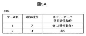
- the control unit 10 uses the determination table 501 to select the dispensing operation based on the sample type information 402, the measurement item information 403, or the combination of the sample type information 402 and the measurement item information 403 of the measurement request information data 401.
- FIG. 5A is an example of a determination table 501a for selecting a dispensing operation based on sample type information.
- a protein contained in a reagent can be considered as an example that may adversely affect the analysis. For example, in the case of a sample originally containing a large amount of protein, it can be said that the analysis result does not change due to the mixing of a small amount of the reagent. Therefore, the determination table 501a is set in association with the sample type and whether or not the carry-over avoidance dispensing operation is applied. Similarly, when the dispensing operation is selected based on the measurement item information, the control unit 10 holds the determination table in which the sample type column of the determination table 501a is changed to the measurement item column.
- FIG. 5B is an example of the determination table 501b that selects the dispensing operation based on the combination of the sample type information and the measurement item information. Some measurement items use only reagents that do not affect the analysis results even if mixed. By using the determination table 501b, the carry-over avoidance dispensing operation can be performed only for the combination of the sample type and the measurement item that affect the measurement result.
- Modification 1 The remaining sample that has been dispensed into the first reaction vessel 2a should be discarded if it affects the measurement items, but if there is no effect on the measurement items, the first one is continuously used. It is permissible to dispense into the reaction vessel 2a and perform another measurement using the remaining sample.
- the application of the carry-over avoidance dispensing operation is determined by the sample type information, the measurement item information, or the combination of the sample type information and the measurement item information, but other information such as an automatic analyzer is shown.
- the application of the carryover avoidance dispensing operation may be determined based on the state of.
- the carryover avoidance dispensing operation is applied. If maintenance of the dispensing nozzle is not performed, contamination risk is likely to occur. Therefore, the carry-over avoidance dispensing operation is applied so that contamination due to contamination of the dispensing nozzle does not occur. .. Whether or not maintenance of the dispensing nozzle has been performed can be determined from the operation log of the device.
- the carryover avoidance dispensing operation is applied regardless of the sample type.
- the dispensing nozzle is dirty as the cause of the QC measurement result being out of the standard range. Therefore, a carry-over avoidance dispensing operation is applied so that contamination due to contamination of the dispensing nozzle does not occur.
- Incubator 2 Reaction container 3: Reagent / sample common storage part 4: Reagent container 4b: Reagent bottle 5: Specimen container, 6: Dispensing mechanism, 7: Washing tank, 8: Spectral photometer, 10: Control unit, 201: Dispensing nozzle, 401: Measurement request information data, 402: Specimen type information, 403: Measurement item information, 501: Judgment table.
Landscapes
- Physics & Mathematics (AREA)
- Health & Medical Sciences (AREA)
- Life Sciences & Earth Sciences (AREA)
- Chemical & Material Sciences (AREA)
- Analytical Chemistry (AREA)
- Biochemistry (AREA)
- General Health & Medical Sciences (AREA)
- General Physics & Mathematics (AREA)
- Immunology (AREA)
- Pathology (AREA)
- Automatic Analysis And Handling Materials Therefor (AREA)
Priority Applications (4)
| Application Number | Priority Date | Filing Date | Title |
|---|---|---|---|
| JP2022568082A JP7499881B2 (ja) | 2020-12-11 | 2021-10-15 | 自動分析装置 |
| EP21903012.9A EP4261545A4 (en) | 2020-12-11 | 2021-10-15 | AUTOMATIC ANALYSIS DEVICE |
| CN202180073840.9A CN116438460B (zh) | 2020-12-11 | 2021-10-15 | 自动分析装置 |
| US18/036,522 US20240012019A1 (en) | 2020-12-11 | 2021-10-15 | Automatic analyzer |
Applications Claiming Priority (2)
| Application Number | Priority Date | Filing Date | Title |
|---|---|---|---|
| JP2020-205500 | 2020-12-11 | ||
| JP2020205500 | 2020-12-11 |
Publications (1)
| Publication Number | Publication Date |
|---|---|
| WO2022123908A1 true WO2022123908A1 (ja) | 2022-06-16 |
Family
ID=81973535
Family Applications (1)
| Application Number | Title | Priority Date | Filing Date |
|---|---|---|---|
| PCT/JP2021/038191 Ceased WO2022123908A1 (ja) | 2020-12-11 | 2021-10-15 | 自動分析装置 |
Country Status (5)
| Country | Link |
|---|---|
| US (1) | US20240012019A1 (https=) |
| EP (1) | EP4261545A4 (https=) |
| JP (1) | JP7499881B2 (https=) |
| CN (1) | CN116438460B (https=) |
| WO (1) | WO2022123908A1 (https=) |
Cited By (1)
| Publication number | Priority date | Publication date | Assignee | Title |
|---|---|---|---|---|
| WO2024161812A1 (ja) | 2023-02-03 | 2024-08-08 | 株式会社日立ハイテク | 自動分析装置 |
Citations (6)
| Publication number | Priority date | Publication date | Assignee | Title |
|---|---|---|---|---|
| JPH11352132A (ja) * | 1998-06-05 | 1999-12-24 | Aloka Co Ltd | ノズル装置 |
| JP2001074756A (ja) * | 1999-08-31 | 2001-03-23 | Hitachi Ltd | 検体の前処理装置 |
| JP2019120509A (ja) * | 2017-12-28 | 2019-07-22 | シスメックス株式会社 | 検体測定装置および検体測定方法 |
| JP2019163991A (ja) * | 2018-03-19 | 2019-09-26 | 株式会社日立ハイテクノロジーズ | 自動分析装置 |
| WO2020071163A1 (ja) * | 2018-10-02 | 2020-04-09 | 株式会社日立ハイテクノロジーズ | 自動分析装置 |
| WO2020235134A1 (ja) * | 2019-05-21 | 2020-11-26 | 株式会社日立ハイテク | 自動分析装置 |
Family Cites Families (3)
| Publication number | Priority date | Publication date | Assignee | Title |
|---|---|---|---|---|
| US3912456A (en) * | 1974-03-04 | 1975-10-14 | Anatronics Corp | Apparatus and method for automatic chemical analysis |
| JPS55140156A (en) * | 1979-04-19 | 1980-11-01 | Olympus Optical Co Ltd | Distribution method |
| JP6878593B2 (ja) * | 2016-12-23 | 2021-05-26 | エフ.ホフマン−ラ ロシュ アーゲーF. Hoffmann−La Roche Aktiengesellschaft | 体外診断システムの吸引プローブの洗浄方法、体外診断方法及び体外診断システム |
-
2021
- 2021-10-15 US US18/036,522 patent/US20240012019A1/en active Pending
- 2021-10-15 EP EP21903012.9A patent/EP4261545A4/en active Pending
- 2021-10-15 WO PCT/JP2021/038191 patent/WO2022123908A1/ja not_active Ceased
- 2021-10-15 CN CN202180073840.9A patent/CN116438460B/zh active Active
- 2021-10-15 JP JP2022568082A patent/JP7499881B2/ja active Active
Patent Citations (6)
| Publication number | Priority date | Publication date | Assignee | Title |
|---|---|---|---|---|
| JPH11352132A (ja) * | 1998-06-05 | 1999-12-24 | Aloka Co Ltd | ノズル装置 |
| JP2001074756A (ja) * | 1999-08-31 | 2001-03-23 | Hitachi Ltd | 検体の前処理装置 |
| JP2019120509A (ja) * | 2017-12-28 | 2019-07-22 | シスメックス株式会社 | 検体測定装置および検体測定方法 |
| JP2019163991A (ja) * | 2018-03-19 | 2019-09-26 | 株式会社日立ハイテクノロジーズ | 自動分析装置 |
| WO2020071163A1 (ja) * | 2018-10-02 | 2020-04-09 | 株式会社日立ハイテクノロジーズ | 自動分析装置 |
| WO2020235134A1 (ja) * | 2019-05-21 | 2020-11-26 | 株式会社日立ハイテク | 自動分析装置 |
Non-Patent Citations (1)
| Title |
|---|
| See also references of EP4261545A4 * |
Cited By (2)
| Publication number | Priority date | Publication date | Assignee | Title |
|---|---|---|---|---|
| WO2024161812A1 (ja) | 2023-02-03 | 2024-08-08 | 株式会社日立ハイテク | 自動分析装置 |
| EP4660634A1 (en) | 2023-02-03 | 2025-12-10 | Hitachi High-Tech Corporation | Automatic analysis device |
Also Published As
| Publication number | Publication date |
|---|---|
| US20240012019A1 (en) | 2024-01-11 |
| CN116438460A (zh) | 2023-07-14 |
| JPWO2022123908A1 (https=) | 2022-06-16 |
| JP7499881B2 (ja) | 2024-06-14 |
| EP4261545A4 (en) | 2024-10-23 |
| CN116438460B (zh) | 2025-10-28 |
| EP4261545A1 (en) | 2023-10-18 |
Similar Documents
| Publication | Publication Date | Title |
|---|---|---|
| JP5178830B2 (ja) | 自動分析装置 | |
| EP2878956B1 (en) | Automated analyzer | |
| JP7189339B2 (ja) | 自動分析装置 | |
| JP6928712B2 (ja) | 自動分析装置 | |
| JP7292195B2 (ja) | 自動分析装置 | |
| WO2017145672A1 (ja) | 自動分析装置および洗浄方法 | |
| US11965903B2 (en) | Automated analyzer and method of controlling automated analyzer | |
| WO2022176556A1 (ja) | 自動分析装置、および自動分析装置における検体の吸引方法 | |
| JP7499881B2 (ja) | 自動分析装置 | |
| US20190369130A1 (en) | Automatic Analyzer | |
| JP7725621B2 (ja) | 自動分析装置及び自動分析方法 | |
| JP6745407B2 (ja) | 自動分析装置 | |
| JP5606843B2 (ja) | 自動分析装置 | |
| JP6791690B2 (ja) | 自動分析装置 | |
| JP7054616B2 (ja) | 自動分析装置 | |
| JP7720410B2 (ja) | 自動分析装置 | |
| JP6004398B2 (ja) | 自動分析装置 | |
| JP5192316B2 (ja) | 自動分析装置 | |
| JPH0798320A (ja) | 生化学自動分析装置 | |
| WO2024219094A1 (ja) | 自動分析装置及び自動分析方法 | |
| WO2026070070A1 (ja) | 自動分析装置 | |
| JP2016040535A (ja) | 自動分析装置および自動分析装置の制御方法 | |
| JP2010117176A (ja) | 分析装置とその分注制御方法 | |
| JP2010210249A (ja) | 生化学自動分析装置のための分注方法および装置 |
Legal Events
| Date | Code | Title | Description |
|---|---|---|---|
| 121 | Ep: the epo has been informed by wipo that ep was designated in this application |
Ref document number: 21903012 Country of ref document: EP Kind code of ref document: A1 |
|
| DPE2 | Request for preliminary examination filed before expiration of 19th month from priority date (pct application filed from 20040101) | ||
| WWE | Wipo information: entry into national phase |
Ref document number: 18036522 Country of ref document: US |
|
| ENP | Entry into the national phase |
Ref document number: 2022568082 Country of ref document: JP Kind code of ref document: A |
|
| NENP | Non-entry into the national phase |
Ref country code: DE |
|
| ENP | Entry into the national phase |
Ref document number: 2021903012 Country of ref document: EP Effective date: 20230711 |
|
| WWG | Wipo information: grant in national office |
Ref document number: 202180073840.9 Country of ref document: CN |