WO2022118599A1 - 機器制御システム - Google Patents
機器制御システム Download PDFInfo
- Publication number
- WO2022118599A1 WO2022118599A1 PCT/JP2021/040491 JP2021040491W WO2022118599A1 WO 2022118599 A1 WO2022118599 A1 WO 2022118599A1 JP 2021040491 W JP2021040491 W JP 2021040491W WO 2022118599 A1 WO2022118599 A1 WO 2022118599A1
- Authority
- WO
- WIPO (PCT)
- Prior art keywords
- air
- room
- control
- temperature
- ventilation
- Prior art date
- Legal status (The legal status is an assumption and is not a legal conclusion. Google has not performed a legal analysis and makes no representation as to the accuracy of the status listed.)
- Ceased
Links
Images





Classifications
-
- F—MECHANICAL ENGINEERING; LIGHTING; HEATING; WEAPONS; BLASTING
- F24—HEATING; RANGES; VENTILATING
- F24F—AIR-CONDITIONING; AIR-HUMIDIFICATION; VENTILATION; USE OF AIR CURRENTS FOR SCREENING
- F24F11/00—Control or safety arrangements
- F24F11/50—Control or safety arrangements characterised by user interfaces or communication
- F24F11/54—Control or safety arrangements characterised by user interfaces or communication using one central controller connected to several sub-controllers
-
- F—MECHANICAL ENGINEERING; LIGHTING; HEATING; WEAPONS; BLASTING
- F24—HEATING; RANGES; VENTILATING
- F24F—AIR-CONDITIONING; AIR-HUMIDIFICATION; VENTILATION; USE OF AIR CURRENTS FOR SCREENING
- F24F11/00—Control or safety arrangements
- F24F11/62—Control or safety arrangements characterised by the type of control or by internal processing, e.g. using fuzzy logic, adaptive control or estimation of values
- F24F11/63—Electronic processing
- F24F11/64—Electronic processing using pre-stored data
-
- F—MECHANICAL ENGINEERING; LIGHTING; HEATING; WEAPONS; BLASTING
- F24—HEATING; RANGES; VENTILATING
- F24F—AIR-CONDITIONING; AIR-HUMIDIFICATION; VENTILATION; USE OF AIR CURRENTS FOR SCREENING
- F24F11/00—Control or safety arrangements
- F24F11/62—Control or safety arrangements characterised by the type of control or by internal processing, e.g. using fuzzy logic, adaptive control or estimation of values
- F24F11/63—Electronic processing
- F24F11/65—Electronic processing for selecting an operating mode
-
- F—MECHANICAL ENGINEERING; LIGHTING; HEATING; WEAPONS; BLASTING
- F24—HEATING; RANGES; VENTILATING
- F24F—AIR-CONDITIONING; AIR-HUMIDIFICATION; VENTILATION; USE OF AIR CURRENTS FOR SCREENING
- F24F11/00—Control or safety arrangements
- F24F11/70—Control systems characterised by their outputs; Constructional details thereof
- F24F11/72—Control systems characterised by their outputs; Constructional details thereof for controlling the supply of treated air, e.g. its pressure
-
- F—MECHANICAL ENGINEERING; LIGHTING; HEATING; WEAPONS; BLASTING
- F24—HEATING; RANGES; VENTILATING
- F24F—AIR-CONDITIONING; AIR-HUMIDIFICATION; VENTILATION; USE OF AIR CURRENTS FOR SCREENING
- F24F11/00—Control or safety arrangements
- F24F11/70—Control systems characterised by their outputs; Constructional details thereof
- F24F11/80—Control systems characterised by their outputs; Constructional details thereof for controlling the temperature of the supplied air
-
- F—MECHANICAL ENGINEERING; LIGHTING; HEATING; WEAPONS; BLASTING
- F24—HEATING; RANGES; VENTILATING
- F24F—AIR-CONDITIONING; AIR-HUMIDIFICATION; VENTILATION; USE OF AIR CURRENTS FOR SCREENING
- F24F7/00—Ventilation
- F24F7/007—Ventilation with forced flow
-
- F—MECHANICAL ENGINEERING; LIGHTING; HEATING; WEAPONS; BLASTING
- F24—HEATING; RANGES; VENTILATING
- F24F—AIR-CONDITIONING; AIR-HUMIDIFICATION; VENTILATION; USE OF AIR CURRENTS FOR SCREENING
- F24F2110/00—Control inputs relating to air properties
- F24F2110/10—Temperature
-
- F—MECHANICAL ENGINEERING; LIGHTING; HEATING; WEAPONS; BLASTING
- F24—HEATING; RANGES; VENTILATING
- F24F—AIR-CONDITIONING; AIR-HUMIDIFICATION; VENTILATION; USE OF AIR CURRENTS FOR SCREENING
- F24F2110/00—Control inputs relating to air properties
- F24F2110/20—Humidity
-
- F—MECHANICAL ENGINEERING; LIGHTING; HEATING; WEAPONS; BLASTING
- F24—HEATING; RANGES; VENTILATING
- F24F—AIR-CONDITIONING; AIR-HUMIDIFICATION; VENTILATION; USE OF AIR CURRENTS FOR SCREENING
- F24F2110/00—Control inputs relating to air properties
- F24F2110/50—Air quality properties
- F24F2110/64—Airborne particle content
-
- F—MECHANICAL ENGINEERING; LIGHTING; HEATING; WEAPONS; BLASTING
- F24—HEATING; RANGES; VENTILATING
- F24F—AIR-CONDITIONING; AIR-HUMIDIFICATION; VENTILATION; USE OF AIR CURRENTS FOR SCREENING
- F24F2110/00—Control inputs relating to air properties
- F24F2110/50—Air quality properties
- F24F2110/65—Concentration of specific substances or contaminants
- F24F2110/70—Carbon dioxide
Definitions
- This disclosure relates to a device control system.
- Patent Document 1 A technique has been proposed that enables efficient energy-saving operation when the air conditioner and the ventilation fan are operated at the same time (see, for example, Patent Document 1).
- an air supply purification fan that purifies the air flowing from the outside to the room and supplies the purified air to the room.
- the outdoor air is taken into the room by the air supply purification fan, the temperature or humidity of the taken-in outdoor air affects the temperature or humidity of the indoor air.
- the present inventor has conceived a technique for appropriately coordinating the air supply purifying fan and the air conditioner.
- the purpose of this disclosure is to provide a technique for appropriately coordinating an air supply purifying fan and an air conditioner.
- the device control system of one aspect of the present disclosure purifies the air flowing from the outside to the room, and supplies the purified air to the room to ventilate the room.
- an air conditioner for air conditioning in the room and a control device for controlling the air supply purification fan and the air conditioner.
- the control device sequentially executes control for ventilation in the room and control for air conditioning in the room.
- the air supply purifying fan and the air conditioner can be suitably coordinated.
- FIG. 1 is a diagram showing a configuration of a device control system according to an embodiment.
- FIG. 2 is a block diagram showing a functional block of each device of FIG.
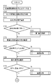
- FIG. 3 is a flowchart showing the operation of the server.
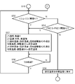
- FIG. 4 is a flowchart showing the operation of the server following FIG.
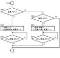
- FIG. 5 is a flowchart showing the details of the first ventilation control of S18 of FIG.
- FIG. 6 is a flowchart showing the details of the temperature control of S24 of FIG.
- FIG. 7 is a flowchart showing the details of the humidity control in S30 of FIG.
- FIG. 8 is a flowchart showing the details of the second ventilation control of S36 of FIG.
- the subject of the device or method in this disclosure is equipped with a computer. By executing the program by this computer, the function of the subject of the device or method in the present disclosure is realized.
- a computer has a processor that operates according to a program as a main hardware configuration. The type of processor does not matter as long as the function can be realized by executing the program.
- the processor is composed of one or a plurality of electronic circuits including a semiconductor integrated circuit (Integrated Circuit) or an LSI (Large Scale Integration). Although it is called IC or LSI here, the name changes depending on the degree of integration, and it may be called system LSI, VLSI (Very Large Scale Integration) or USLI (Ultra Large Scale Integration).
- a field programmable gate array (Field Programmable Gate Array) programmed after the LSI is manufactured, or a reconfigurable logic device that can reconfigure the junction relationship inside the LSI or set up the circuit partition inside the LSI for the same purpose. Can be used in.
- a plurality of electronic circuits may be integrated on one chip or may be provided on a plurality of chips.
- a plurality of chips may be integrated into one device, or may be provided in a plurality of devices.
- the program is recorded on a non-temporary recording medium such as a computer-readable ROM (Read Only Memory), an optical disk, or a hard disk drive.
- the program may be stored in a recording medium in advance, or may be supplied to the recording medium via a wide area communication network including the Internet or the like.
- FIG. 1 shows the configuration of the device control system 1000 of the embodiment.
- the equipment control system 1000 includes an air conditioner 200, an outside air passage 300, an exhaust air passage 302, a heat exchanger 310, an air supply purification fan 312, an exhaust port 340, a user terminal 350, and a server 360.
- the elements other than the server 360 are installed in facilities such as houses.
- the device control system 1000 regulates the temperature and humidity of the room 100 in the facility and purifies the air in the room 100.
- a ceiling 110 is arranged on the upper surface of the room 100.
- a wall surface 120 is arranged on the side surface of the room 100, and a floor surface 130 is arranged on the lower surface of the room 100.
- An air conditioner 200 is installed on the wall surface 120.
- the air conditioned device 200 harmonizes the air in the room 100.
- the air conditioner 200 has a cooling function and a dehumidifying function, and regulates the temperature and humidity of the room 100.
- the air conditioner 200 may further have a heating function.
- the air volume level of the air conditioner 200 has "strong” and "weak".
- the air volume level "strong” is an air volume defined in the range of 10 to 30 m 3 / min
- the air volume level "weak” is a smaller air volume than the air volume level "strong”.
- the air conditioner 200 is composed of a combination of an indoor unit and an outdoor unit, but here, the outdoor unit will be omitted and the indoor unit will be described as the air conditioner 200.
- the air conditioner includes an air outlet (not shown), which blows air-conditioned air 500, which is temperature- or humidity-controlled air, toward the central portion of the room 100.
- the outside of the facility having the indoor 100 is the outdoor 102, and the ducts connecting the outdoor 102 and the indoor 100 are the outside air passage 300 and the exhaust air passage 302.
- the outside air passage 300 and the exhaust air passage 302 are connected to the heat exchanger 310 in the middle portion.
- the heat exchanger 310 performs heat exchange between the air passing through the outside air passage 300 and the air passing through the exhaust air passage 302.
- an air supply purification fan 312 is provided on the indoor 100 side of the heat exchanger 310.
- the air supply purifying fan 312 is installed on the wall surface 120, but the installation position of the air supply purifying fan 312 is not limited to this.
- the air supply purifying fan 312 may be installed on the ceiling 110.
- the air supply purification fan 312 is an air supply type ventilation fan that ventilates the room 100 by purifying the air flowing from the outdoor 102 toward the room 100 and supplying the purified air to the room 100. In other words, the air supply purifying fan 312 ventilates and purifies the air in the room 100. In the embodiment, the air supply purifying fan 312 lowers the carbon dioxide (CO 2 ) concentration and the PM2.5 concentration in the room 100.
- CO 2 carbon dioxide
- the air supply purification fan 312 includes a blower 320, an IAQ (Indoor Air Quality) remote controller 322, and an air supply port 330 with a purification filter.
- the blower 320 has a fan, and by rotating the fan, air is flowed from the outdoor 102 to the indoor 100 through the outside air passage 300. That is, the air in the outdoor 102 (that is, the outside air) flows into the outdoor air passage 300 and heads toward the indoor 100.
- the IAQ remote controller 322 is a device for remotely controlling the operation of the blower 320.
- the IAQ remote controller 322 and the blower 320 are connected by wire or wirelessly.
- the air volume level of the air supply purifying fan 312 (blower 320) is 6 levels from “0" to "5".
- the air volume at each air volume level is set to an air volume divided into 6 stages between 0 and 300 CMH (Cubic Meter per Hour, that is, m 3 / hour). However, the air volume level "0" is set to 0 CMH, and the larger the air volume level, the larger the air volume.
- the air supply port 330 with a purification filter is provided at the indoor end of the outside air passage 300 and incorporates a purification filter (not shown).
- An example of a purification filter is a non-woven fabric.
- the non-woven fabric has a function of capturing mist particles (for example, PM2.5) suspended in the air, bacteria, molds, viruses, allergens and the like. Therefore, the purification filter purifies the air flowing from the outdoor 102 toward the indoor 100 through the outdoor air passage 300 by the blower 320.
- the air supply port 330 with a purification filter causes the air purified by the purification filter to flow into the room 100 as the supply air 502.
- An exhaust port 340 is provided at the indoor end of the exhaust air passage 302.
- the air existing in the room 100 is pushed out by the supply air 502 and flows into the exhaust air passage 302 from the exhaust port 340.
- the air that has flowed into the exhaust air passage 302 is exhausted to the outdoor 102 through the exhaust air passage 302. Therefore, it can be said that the exhaust port 340 exhausts the air in the room 100 to the outside 102.
- a blower may be provided in the exhaust air passage 302. By rotating the fan, the blower causes air to flow from the indoor 100 to the outdoor 102 through the exhaust air passage 302.
- the user terminal 350 is an information processing terminal operated by a user (for example, a resident of a facility).
- the user terminal 350 may be, for example, a smartphone or a tablet terminal.
- the user terminal 350 is installed in the room 100, but there is no limitation on the installation position of the user terminal 350.
- the user terminal 350 may be installed in the outdoor 102.
- the server 360 is a control device having a function of controlling the air conditioner 200 and the air supply purification fan 312.
- the server 360 may be, for example, an information processing device arranged on the cloud.
- the server 360 transmits / receives signals to / from the air conditioner 200, the IAQ remote controller 322, and the user terminal 350 via a communication network 370 including a LAN (Local Area Network), a WAN (Wide Area Network), or the Internet.
- LAN Local Area Network
- WAN Wide Area Network
- FIG. 2 is a block diagram showing a functional block of each device of FIG.
- Each block shown in the block diagram of the present disclosure can be realized by an element or a mechanical device such as a CPU (Central Processing Unit) and a memory of a computer in terms of hardware, and can be realized by a computer program or the like in terms of software.
- a CPU Central Processing Unit
- the functional blocks realized by their cooperation are drawn. It will be understood by those skilled in the art that these functional blocks can be realized in various ways by a combination of hardware and software.
- the user terminal 350 includes a communication unit 10 and a cooperative operation instruction unit 12.
- the communication unit 10 communicates with an external device according to a predetermined communication protocol.
- the cooperative operation instruction unit 12 transmits data instructing the start or stop of the cooperative operation of the air conditioner 200 and the air supply purification fan 312 to the server 360 via the communication unit 10 in response to the user's operation. ..
- the function of the cooperative operation instruction unit 12 may be implemented in the application program.
- the CPU of the user terminal 350 may exert the function of the cooperative operation instruction unit 12 by executing the application program.
- the air conditioner 200 includes a communication unit 20, a control unit 22, a temperature sensor 24, and a humidity sensor 26.
- the temperature sensor 24 detects the temperature of the room 100
- the humidity sensor 26 detects the humidity of the room 100.
- Both the temperature sensor 24 and the humidity sensor 26 can be said to be sensors that detect the state of the room 100 related to the control of the air conditioner 200.
- Both the temperature sensor 24 and the humidity sensor 26 may be installed at the suction port (not shown) of the air conditioner 200.
- the communication unit 20 communicates with an external device according to a predetermined communication protocol.
- the control unit 22 controls the operation of the air conditioner 200.
- the control unit 22 of the air conditioner 200 is based on the temperature information detected by the temperature sensor 24 and the humidity information detected by the humidity sensor 26. The air volume may be determined. Further, the control unit 22 transmits and receives various data (temperature information, humidity information, control signals, etc.) to and from the server 360 via the communication unit 20.
- the air supply purification fan 312 is equipped with a blower 320 and an IAQ remote controller 322.
- the blower 320 includes a communication unit 30 and a fan control unit 32.
- the communication unit 30 communicates with an external device (IAQ remote controller 322 in the embodiment) according to a predetermined communication protocol.
- the fan control unit 32 controls the air volume of the blower 320 by controlling the rotational operation of the fan (not shown) of the blower 320 according to the instruction from the IAQ remote controller 322.
- the IAQ remote controller 322 includes a communication unit 40, a control unit 42, a storage unit 44, a carbon dioxide sensor (CO 2 sensor) 46, and a PM2.5 sensor 48.
- the CO 2 sensor 46 detects the CO 2 concentration in the room 100.
- the PM2.5 sensor 48 detects the PM2.5 concentration in the room 100. Both the CO 2 sensor 46 and the PM2.5 sensor 48 can be said to be sensors that detect the state of the room 100 related to the control of the air supply purification fan 312.
- the communication unit 40 communicates with an external device according to a predetermined communication protocol.
- the control unit 42 controls the operation of the air supply purifying fan 312 (blower 320). Further, the control unit 42 transmits and receives various data (CO 2 concentration, PM2.5 concentration, control signal, etc.) to and from the server 360 via the communication unit 40. Further, the control unit 42 transmits and receives various data (control signals and the like) to and from the blower 320 via the communication unit 40.
- the storage unit 44 stores an air volume switching table (which can be said to be an air volume switching reference) for automatic operation of the air supply purification fan 312 (blower 320).
- the air volume switching table may include a first air volume switching table and a second air volume switching table.
- the first air volume switching table may determine the air volume level according to the PM2.5 concentration.
- the setting range of the air volume switching concentration of PM2.5 may be, for example, in the range of 10 ⁇ g (microgram) / m 3 (cubic meter) to 300 ⁇ g / m 3 .
- the second air volume switching table may determine the air volume level according to the CO 2 concentration.
- the CO 2 concentration for switching to the air volume level “5” may be in the range of 500 ppm (parts per million) to 5000 ppm.
- the CO 2 concentration used as the switching standard from the air volume level “1” to the air volume level “4” is smaller than the CO 2 concentration used as the switching standard for the air volume level “5”.
- the server 360 includes a communication unit 50, a sensor information acquisition unit 52, an operation state acquisition unit 54, a cooperative operation control unit 56, and a storage unit 58.
- the communication unit 50 communicates with the external device according to a predetermined communication protocol.
- the storage unit 58 stores a computer program in which an algorithm for coordinating the air conditioner 200 and the air supply purifying fan 312 (hereinafter referred to as “cooperative operation algorithm”) is implemented.
- the computer program (in other words, a cooperative operation algorithm) may include the contents of the first air volume switching table and the second air volume switching table.
- the CPU of the server 360 may exert the functions of the sensor information acquisition unit 52, the operation state acquisition unit 54, and the cooperative operation control unit 56 by executing the computer program.
- the sensor information acquisition unit 52 acquires the temperature information detected by the temperature sensor 24 and the humidity information detected by the humidity sensor 26 from the air conditioner 200 via the communication unit 50. Further, the sensor information acquisition unit 52 acquires the CO 2 concentration information detected by the CO 2 sensor 46 and the PM2.5 concentration information detected by the PM2.5 sensor 48 from the IAQ remote controller 322 via the communication unit 50. do. The sensor information acquisition unit 52 repeatedly acquires temperature information, humidity information, CO 2 concentration information, and PM2.5 concentration information in a predetermined cycle (for example, 5 minutes).
- the operation state acquisition unit 54 acquires the operation state (on / off, set temperature, etc.) of the air conditioner 200 from the air conditioner 200 via the communication unit 50. Further, the operating state acquisition unit 54 acquires the operating state (on / off, air volume, etc.) of the air supply purifying fan 312 from the IAQ remote controller 322 via the communication unit 50.
- the user terminal 350 instructs the cooperative operation control unit 56 to start the cooperative operation
- (1) the temperature information, the humidity information, the CO 2 concentration, and the PM2.5 concentration acquired by the sensor information acquisition unit 52 are combined with each other.
- the air in the outdoor 102 is hot and humid.
- the equipment control system 1000 will be constructed in a hot and humid area. Therefore, when the air supply purifying fan 312 takes in the hot and humid air from the outdoor 102 into the indoor 100, the efficiency of air conditioning (that is, cooling efficiency and dehumidifying efficiency) by the air conditioning device 200 decreases. Therefore, the coordinated operation control unit 56 of the embodiment controls for ventilation of the room 100 (first ventilation control and second ventilation control described later) and control for air conditioning of the room 100 (temperature control described later). And humidity control) are executed sequentially instead of being executed in parallel. As a result, it is possible to suppress a decrease in the efficiency of air conditioning by the air conditioning device 200, and to efficiently and quickly realize air conditioning and air purification in the room 100.
- the cooperative operation control unit 56 determines the state of the room 100 ( CO2 concentration and PM2.5 concentration in the embodiment) detected by the sensor that detects the state of the room 100 related to the control of the air supply purification fan 312. Based on the state of the room 100 (temperature and humidity in the embodiment) detected by the sensor that detects the state of the room 100 related to the control of the air conditioner 200, the control for ventilation of the room 100 and the control for ventilation of the room 100, Selectively perform any of the controls for air conditioning in the room 100. As a result, it is possible to suppress a decrease in the efficiency of air conditioning by the air conditioning device 200, and to efficiently and quickly realize air conditioning and air purification in the room 100.
- control for ventilation includes a first ventilation control when the air pollution degree of the room 100 is relatively high and a second ventilation control when the air pollution degree of the room 100 is relatively low. ..
- the cooperative operation control unit 56 preferentially executes the first ventilation control, the control for air conditioning (that is, temperature control and humidity control), and the second ventilation control.
- the control for air conditioning that is, temperature control and humidity control
- the second ventilation control A person is sensitive in the order of temperature, humidity, and air quality (cleanliness), but according to the above configuration, the comfort of the room 100 can be rapidly increased while considering the health of the person in the room 100.
- the cooperative operation control unit 56 determines the mode of air supply by the air supply purification fan 312 based on the temperature of the room 100 and the set temperature of the air conditioning device 200.
- the mode of air supply by the air supply purification fan 312 is determined based on the difference between the measured temperature in the room 100 and the set temperature of the air conditioner 200. As a result, it is possible to suppress a decrease in the efficiency of air conditioning by the air conditioning device 200, or it is possible to efficiently realize temperature adjustment in the room 100. If the temperature of the room 100 should be lowered, the cooperative operation control unit 56 may stop the air supply by the air supply purification fan 312. On the other hand, if the temperature of the room 100 should be raised, the air supply by the air supply purification fan 312 may be continued.
- the cooperative operation control unit 56 determines the mode of air supply by the air supply purification fan 312 based on the humidity of the room 100 and the predetermined humidity reference value.
- the mode of air supply by the air supply purification fan 312 is determined based on the magnitude relationship between the measured humidity in the room 100 and the reference value of humidity.
- the cooperative operation control unit 56 may stop the air supply by the air supply purification fan 312 when the humidity in the room 100 should be lowered.
- the air supply by the air supply purification fan 312 may be continued.
- the coordinated operation control unit 56 lowers the set temperature of the air conditioner 200 from the value up to that point in the control for ventilation. As a result, it is possible to prevent the temperature of the room 100 from rising rapidly due to the air supply operation by the air supply purification fan 312 (that is, the ventilation of the room 100 by the air in the outdoor 102). In other words, it is possible to prevent the comfort of the room 100 from rapidly decreasing.
- FIG. 3 is a flowchart showing the operation of the server 360.
- the user starts an application for setting cooperative operation on the user terminal 350, and inputs an operation instructing the start of cooperative operation to the application.
- the cooperative operation instruction unit 12 of the user terminal 350 transmits an instruction to start cooperative operation to the server 360.
- the server 360 receives the instruction to start the cooperative operation transmitted from the user terminal 350 (S10).
- the sensor information acquisition unit 52 of the server 360 acquires temperature information and humidity information of the room 100 from the air conditioner 200, and acquires the CO 2 concentration and PM 2.5 concentration of the room 100 from the IAQ remote controller 322. As described above, the sensor information acquisition unit 52 repeatedly acquires the latest temperature information, humidity information, CO 2 concentration, and PM2.5 concentration in a predetermined cycle (for example, a 5-minute cycle). Further, the operation state acquisition unit 54 of the server 360 inquires of the air conditioner 200 for the operation state of the air conditioner 200, and inquires of the IAQ remote controller 322 for the operation state of the air supply purification fan 312 (S12). ..
- the cooperative operation control unit 56 of the server 360 confirms the degree of air pollution in the room 100 based on the CO 2 concentration and the PM2.5 concentration in the room 100 (S14).
- the cooperative operation control unit 56 determines that the degree of air pollution is high (Y in S16)
- the cooperative operation control unit 56 executes the first ventilation control (S18).
- the operation mode of the air supply purification fan 312 is determined according to the contents of the first air volume switching table and the contents of the second air volume switching table. The details of the first ventilation control will be described later.
- the cooperative operation control unit 56 satisfies at least one of the case where the CO 2 concentration is equal to or higher than the predetermined CO 2 threshold value A1 and the case where the PM2.5 concentration is larger than the predetermined PM2.5 threshold value A2. In addition, it is judged that the degree of air pollution is high. If the cooperative operation control unit 56 does not determine that the degree of air pollution is high (specifically, when the CO 2 concentration is less than the CO 2 threshold value A1 and the PM2.5 concentration is less than the PM2.5 threshold value A2) (N of S16). ), The process of S18 is skipped.
- the cooperative operation control unit 56 of the server 360 confirms the difference between the temperature of the room 100 and the set temperature of the air conditioner 200 (S20).
- the cooperative operation control unit 56 executes temperature control (S24). The details of temperature control will be described later. If the difference between the room temperature and the set temperature is within ⁇ 1 ° C. (Y in S22), the processing in S24 is skipped.
- the cooperative operation control unit 56 of the server 360 confirms the humidity of the room 100 (S26).
- the humidity of the room 100 is 40% or less, which is the first reference value (lower limit of comfort) of the predetermined humidity, or the second reference value of the predetermined humidity (the lower limit of comfort). If it is 60% or more (N of S28), which is the upper limit of comfort), humidity control is executed (S30). The details of humidity control will be described later. If the humidity of the room 100 is in the range of 40% to 60% (hereinafter, also referred to as "comfort zone") (Y of S28), the process of S30 is skipped.
- FIG. 4 is a flowchart showing the operation of the server 360 following FIG.
- the cooperative operation control unit 56 confirms the degree of air pollution in the room 100 based on the CO 2 concentration and the PM2.5 concentration in the room 100 (S32).
- the cooperative operation control unit 56 determines that the degree of air pollution is not sufficiently low (N in S34)
- the cooperative operation control unit 56 executes the second ventilation control (S36).
- the operation mode of the air supply purification fan 312 is determined according to the contents of the first air volume switching table and the contents of the second air volume switching table. The details of the second ventilation control will be described later.
- the cooperative operation control unit 56 has a CO 2 concentration of less than a predetermined CO 2 threshold B1 (smaller than the CO 2 threshold A1) and a PM2.5 concentration of a predetermined PM2.5 threshold B2 (PM2). If it is less than (5, smaller than the threshold value A2), it is determined that the air pollution degree is sufficiently low. When the cooperative operation control unit 56 determines that the degree of air pollution is sufficiently low (Y in S34), the cooperative operation control unit 56 skips the process of S36.
- the cooperative operation control unit 56 returns the air conditioner 200 and the air supply purification fan 312 to the default settings (S38). Specifically, the cooperative operation control unit 56 transmits a signal instructing that the operating state of the air conditioner 200 is the cooling operation, the air volume is automatic, and the set temperature is the initial temperature, is transmitted to the air conditioner 200. The "initial temperature" in the description of each flowchart is the set temperature set in the air conditioner 200 at the start of the cooperative operation. Further, the cooperative operation control unit 56 transmits a signal instructing that the air volume is automatic to the air supply purification fan 312 (IAQ remote controller 322).
- the sensor information acquisition unit 52 of the server 360 performs temperature information, humidity information, CO 2 concentration, and PM2.5 of the room 100 in a predetermined cycle (for example, every 5 minutes). Get the concentration repeatedly.
- the operation state acquisition unit 54 of the server 360 repeatedly acquires the operation state of the air conditioner 200 and the operation state of the air supply purification fan 312 at a predetermined cycle (for example, every 5 minutes) (S40).
- the cooperative operation control unit 56 of the server 360 carries out the determination of each of S16, S22, S28, and S34 (S42). That is, the cooperative operation control unit 56 determines whether the degree of air pollution is high (in other words, whether it is in a high air pollution state), whether the difference between the temperature of the room 100 and the set temperature is large (whether it is out of temperature), or whether the room 100 is out of temperature. Determine if the humidity is outside the comfort zone (whether it is out of humidity) and if the air pollution level is low enough (in other words, if it is moderately polluted). This determination process may be executed in synchronization with the acquisition of each sensor information (temperature information, etc.), and the execution cycle may be 5 minutes.
- the coordinated operation control unit 56 controls the first ventilation in S18 and the temperature in S24. , S30 humidity control, or S36 second ventilation control (S44).
- S44 second ventilation control
- the coordinated operation control unit 56 controls the first ventilation control, the temperature control, the humidity control, and the second ventilation control in this order. Run. If none of the high air pollution conditions, out-of-temperature, out-of-humidity, or moderate air pollution conditions apply (N in S42), the process in S44 is skipped.
- the server 360 ends the cooperative operation of the air conditioner 200 and the air supply purifying fan 312, and ends the processes shown in FIGS. 3 to 4. After that, the air conditioner 200 and the air supply purifying fan 312 operate independently of each other and autonomously.
- the end condition may be, for example, that the user inputs an operation instructing the stop of the cooperative operation to the user terminal 350, and the server 360 receives the instruction to end the cooperative operation transmitted from the user terminal 350. If the predetermined termination condition is not satisfied (N in S46), the process returns to the process of S42.
- FIG. 5 is a flowchart showing the details of the first ventilation control of S18 of FIG.
- the cooperative operation control unit 56 executes the process of S52. Further, in the cooperative operation control unit 56, if the CO 2 concentration in the room 100 is less than the CO 2 threshold value A1 (N in S50) and the PM2.5 concentration in the room 100 is larger than the PM2.5 threshold value A2 (S54). Y), the process of S52 is executed.
- the cooperative operation control unit 56 sets the air volume level of the air supply purifying fan 312 to "4" as the process of S52. Further, the cooperative operation control unit 56 sets the operation mode of the air conditioner 200 to cooling operation, and sets the air volume level of the air conditioner 200 to “strong”. Further, when the difference between the room temperature and the set temperature is equal to or less than the predetermined temperature difference threshold value A3, the cooperative operation control unit 56 newly sets (initial temperature-adjustment value A4 (adjustment value A4 is larger than 0)). Set as the set temperature.
- the cooperative operation control unit 56 sets a new set temperature (initial temperature-adjustment value B4 (adjustment value B4 is larger than the adjustment value A4)). Set as.
- the cooperative operation control unit 56 waits until 5 minutes have elapsed, that is, until new CO 2 concentration information and PM2.5 concentration information are acquired (N in S56). After 5 minutes have passed (Y in S56), the process returns to S50. If the CO 2 concentration in the room 100 is less than the CO 2 threshold A1 and the PM2.5 concentration in the room 100 is PM2.5 threshold A2 or less (N in S54), the cooperative operation control unit 56 sets the set temperature. Return to the initial temperature (S58).
- FIG. 6 is a flowchart showing the details of the temperature control in S24 of FIG.
- the cooperative operation control unit 56 turns off the air supply operation of the air supply purification fan 312 (air volume level “0”).
- the operation mode of the air conditioner 200 is set to cooling operation, and the air volume level of the air conditioner 200 is set to "strong" (S62).
- S62 air volume level of the air conditioner 200
- the cooperative operation control unit 56 waits until the difference between the temperature of the room 100 and the set temperature is within ⁇ 1 ° C. (N in S64).
- the cooperative operation control unit 56 ends the temperature control process shown in FIG.
- the cooperative operation control unit 56 sets the air volume level of the air supply purifying fan 312 to "1".
- the operation mode of the air conditioner 200 is set to the cooling operation, and the air volume level of the air conditioner 200 is set to "automatic" (S68).
- the temperature of the room 100 is gradually increased.
- the cooperative operation control unit 56 waits until the difference between the temperature in the room 100 and the set temperature is within ⁇ 1 ° C. (N in S70). When the difference between the temperature in the room 100 and the set temperature is within ⁇ 1 ° C.
- the cooperative operation control unit 56 ends the temperature control process shown in FIG. If the difference between the temperature of the room 100 and the set temperature is within ⁇ 1 ° C. in the determination step of S66 (N of S66), the temperature control process shown in FIG. 6 is terminated.
- FIG. 7 is a flowchart showing the details of the humidity control in S30 of FIG.
- the cooperative operation control unit 56 turns off the air supply operation of the air supply purification fan 312 (air volume level “0”), and sets the air conditioner 200.
- the operation mode is set to dehumidifying operation, and the air volume level of the air conditioner 200 is set to "automatic" (S82).
- S82 air volume level of the air conditioner 200
- the cooperative operation control unit 56 waits until the humidity in the room 100 is in the range of 40% to 60% (N in S84).
- the cooperative operation control unit 56 ends the humidity control process shown in FIG. 7.
- the cooperative operation control unit 56 sets the air volume level of the air supply purifying fan 312 to "4" and operates the air conditioner 200.
- the mode is set to cooling operation, and the air volume level of the air conditioner 200 is set to "automatic" (S88). Thereby, the humidity of the room 100 can be efficiently increased.
- the cooperative operation control unit 56 waits until the humidity in the room 100 is in the range of 40% to 60% (N in S90). When the humidity in the room 100 falls within the range of 40% to 60% (Y in S90), the cooperative operation control unit 56 ends the humidity control process shown in FIG. 7. If the humidity in the room 100 is in the range of 40% to 60% (N in S86), the humidity control process shown in FIG. 7 is terminated.
- FIG. 8 is a flowchart showing the details of the second ventilation control of S36 of FIG.
- the cooperative operation control unit 56 determines the air volume of the air supply purification fan 312. The level is set to "1", the operation mode of the air conditioner 200 is set to cooling operation, and the air volume level of the air conditioner 200 is set to "automatic” (S102). The cooperative operation control unit 56 proceeds to the process of S104.
- the cooperative operation control unit 56 sets the air volume level of the air supply purification fan 312 to ". 3 ”, the operation mode of the air conditioner 200 is set to cooling operation, and the air volume level of the air conditioner 200 is set to“ strong ”(S110).
- the cooperative operation control unit 56 waits until the CO 2 concentration in the room 100 becomes CO 2 threshold B1 or less (N in S112), and when the CO 2 concentration becomes CO 2 threshold B1 or less (Y in S112), the process of S104 is performed. Proceed to.
- the cooperative operation control unit 56 executes the first ventilation control shown in FIG.
- the second ventilation control process shown in FIG. 8 may be executed again from S100.
- the cooperative operation control unit 56 determines.
- the air volume level of the air supply purifying fan 312 is set to "1"
- the operation mode of the air conditioner 200 is set to cooling operation
- the air volume level of the air conditioner 200 is set to "automatic” (S106).
- the cooperative operation control unit 56 ends the process of the second ventilation control shown in FIG.
- the cooperative operation control unit 56 determines the air volume of the air supply purification fan 312. The level is set to "2", the operation mode of the air conditioner 200 is set to cooling operation, and the air volume level of the air conditioner 200 is set to "automatic” (S116). The cooperative operation control unit 56 waits until the PM2.5 concentration in the room 100 becomes PM2.5 threshold B2 or less (N in S118), and when the PM2.5 concentration becomes PM2.5 threshold B2 or less (Y in S118). , The process of the second ventilation control shown in FIG. 8 is completed.
- the cooperative operation control unit 56 executes the first ventilation control shown in FIG. 7.
- the second ventilation control process shown in FIG. 8 may be executed again from S100.
- the cooperative operation control unit 56 may reduce the set temperature of the air conditioner 200 by 1 ° C. Further, when the air volume level of the air supply purifying fan 312 is "3" to "5" and the difference between the room temperature and the set temperature is the temperature difference threshold value A3 or less, the cooperative operation control unit 56 is set to air. The set temperature of the harmonizing device 200 may be reduced by 2 ° C. Since the second ventilation control is executed after the temperature control, the difference between the room temperature and the set temperature is equal to or less than the temperature difference threshold value A3.
- the air supply purifying fan 312 and the air conditioner 200 are suitably coordinated to operate based on the coordinated operation algorithm, and the comfort of the air in the room 100 is efficiently improved. Can be done. Further, as described in relation to FIGS. 5 to 8, in the coordinated operation algorithm, each of the first ventilation control, the temperature control, the humidity control, and the second ventilation control is made into a subroutine, and a plurality of indoor environments are generated. The indoor environment can be efficiently improved by executing the subroutine corresponding to the element (temperature, humidity, air quality) whose condition has deteriorated.
- the cooperative operation control unit 56 of the server 360 may execute each of the determinations of S16, S22, S28, and S34 every 5 minutes.
- the cooperative operation control unit 56 may interrupt the control and execute the temperature control even if the humidity control or the second ventilation control is being executed.
- the coordinated operation control unit 56 detects that the temperature does not deviate but the humidity deviates, the controlled operation may be interrupted and the humidity control may be executed even if the second ventilation control is being executed.
- the coordinated operation control unit 56 executes the first ventilation control with the highest priority.
- the device control system 1000 may be constructed in a cold region (for example, a low temperature dry region).
- a cold region for example, a low temperature dry region.
- the server 360 controls the ventilation of the room 100 (first ventilation control and the second ventilation control) and the control for air conditioning of the room 100 (temperature control and humidity control).
- the outline of one aspect of this disclosure is as follows.
- the device control system (1000) of an aspect of the present disclosure purifies the air flowing from the outdoor (102) toward the indoor (100), and supplies the purified air to the indoor (100) to make the indoor (100).
- a control device (200) that controls an air supply purification fan (312) for ventilating, an air conditioner (200) for air conditioning in the room (100), and an air supply purification fan (312) and an air conditioner (200). 360) and.
- the control device (360) sequentially executes control for ventilation in the room (100) and control for air conditioning in the room (100).
- the equipment control system (1000) relates to the control of the first sensor (46, 48) for detecting the state of the room (100) related to the control of the air supply purification fan (312), and the control of the air conditioner (200).
- a second sensor (24, 26) for detecting the state of the room (100) may be further provided.
- the control device (360) is based on the state of the room (100) detected by the first sensor (46, 48) and the state of the room (100) detected by the second sensor (24, 26). , Control for ventilation and control for air conditioning may be selectively performed.
- the control for ventilation includes the first ventilation control when the air pollution degree in the room (100) is relatively high and the second ventilation control when the air pollution degree in the room (100) is relatively low. May include.
- the control device (360) may execute the first ventilation control, the control for air conditioning, and the second ventilation control in the order of priority.
- the control device (360) determines the mode of air supply by the air supply purifying fan (312) based on the temperature of the room (100) and the set temperature of the air conditioner (200) in the control for air conditioning. You may decide.
- the control device (360) determines the mode of air supply by the air supply purification fan (312) based on the humidity of the room (100) and a predetermined reference value of humidity in the control for air conditioning. You may.
- the control device (360) may lower the set temperature of the air conditioner (200) in the control for ventilation.
Landscapes
- Engineering & Computer Science (AREA)
- Chemical & Material Sciences (AREA)
- Combustion & Propulsion (AREA)
- Mechanical Engineering (AREA)
- General Engineering & Computer Science (AREA)
- Signal Processing (AREA)
- Physics & Mathematics (AREA)
- Fuzzy Systems (AREA)
- Mathematical Physics (AREA)
- Human Computer Interaction (AREA)
- Air Conditioning Control Device (AREA)
Priority Applications (1)
| Application Number | Priority Date | Filing Date | Title |
|---|---|---|---|
| JP2022566794A JP7526910B2 (ja) | 2020-12-02 | 2021-11-04 | 機器制御システム |
Applications Claiming Priority (2)
| Application Number | Priority Date | Filing Date | Title |
|---|---|---|---|
| JP2020199981 | 2020-12-02 | ||
| JP2020-199981 | 2020-12-02 |
Publications (1)
| Publication Number | Publication Date |
|---|---|
| WO2022118599A1 true WO2022118599A1 (ja) | 2022-06-09 |
Family
ID=81853648
Family Applications (1)
| Application Number | Title | Priority Date | Filing Date |
|---|---|---|---|
| PCT/JP2021/040491 Ceased WO2022118599A1 (ja) | 2020-12-02 | 2021-11-04 | 機器制御システム |
Country Status (2)
| Country | Link |
|---|---|
| JP (1) | JP7526910B2 (https=) |
| WO (1) | WO2022118599A1 (https=) |
Citations (4)
| Publication number | Priority date | Publication date | Assignee | Title |
|---|---|---|---|---|
| JPH0468252A (ja) * | 1990-07-06 | 1992-03-04 | Mitsubishi Electric Corp | 空調システム |
| JPH04106354A (ja) * | 1990-08-24 | 1992-04-08 | Mitsubishi Electric Corp | 空気調和機 |
| JP2000088320A (ja) * | 1998-09-10 | 2000-03-31 | Mitsubishi Electric Building Techno Service Co Ltd | 自動換気システム |
| JP2016133275A (ja) * | 2015-01-21 | 2016-07-25 | 積水化学工業株式会社 | 換気空調システム及び建物 |
-
2021
- 2021-11-04 JP JP2022566794A patent/JP7526910B2/ja active Active
- 2021-11-04 WO PCT/JP2021/040491 patent/WO2022118599A1/ja not_active Ceased
Patent Citations (4)
| Publication number | Priority date | Publication date | Assignee | Title |
|---|---|---|---|---|
| JPH0468252A (ja) * | 1990-07-06 | 1992-03-04 | Mitsubishi Electric Corp | 空調システム |
| JPH04106354A (ja) * | 1990-08-24 | 1992-04-08 | Mitsubishi Electric Corp | 空気調和機 |
| JP2000088320A (ja) * | 1998-09-10 | 2000-03-31 | Mitsubishi Electric Building Techno Service Co Ltd | 自動換気システム |
| JP2016133275A (ja) * | 2015-01-21 | 2016-07-25 | 積水化学工業株式会社 | 換気空調システム及び建物 |
Also Published As
| Publication number | Publication date |
|---|---|
| JP7526910B2 (ja) | 2024-08-02 |
| JPWO2022118599A1 (https=) | 2022-06-09 |
Similar Documents
| Publication | Publication Date | Title |
|---|---|---|
| CN113418278B (zh) | 用于温湿双控的系统及方法、设备 | |
| JP6754956B2 (ja) | 空調システム、空調システムコントローラ | |
| US11397016B2 (en) | Communications between thermostat and rooftop unit of climate control system | |
| JP3187770B2 (ja) | 空調システムのための湿度制御サーモスタット及び湿度制御方法 | |
| CN106461256A (zh) | 换气装置 | |
| JP2022086037A (ja) | 換気制御システム | |
| WO2020003446A1 (ja) | 空気調和装置 | |
| JP7051489B2 (ja) | 換気システム | |
| JP2017101861A (ja) | 空気制御システム、空気制御方法及び空気制御装置 | |
| JP7630074B2 (ja) | 空調制御システム | |
| JP7526910B2 (ja) | 機器制御システム | |
| KR20190119950A (ko) | 공기조화기 및 공기조화기의 제어방법 | |
| JP2020026888A (ja) | 換気システム | |
| JP4710138B2 (ja) | 加湿機能を有する空気調和機 | |
| CN111380170A (zh) | 空调及空调的控制方法 | |
| JP7395030B2 (ja) | 外気処理装置 | |
| JP7756293B2 (ja) | 換気制御システム | |
| JP2022115248A (ja) | 初期設定方法、コントローラ、および、全館空調システム | |
| CN115335643A (zh) | 换气空气调节系统 | |
| JP4040727B2 (ja) | ファンコイルユニットの温湿度制御装置 | |
| JP2022146981A (ja) | 換気装置 | |
| JP7408376B2 (ja) | 空気調和システム | |
| JP7804881B2 (ja) | 空気調和システム、空気調和システムの制御方法、空気調和装置、及びプログラム | |
| WO2026028912A1 (ja) | 空調システム | |
| WO2024084766A1 (ja) | 換気装置の制御方法、換気装置、換気システム、及びプログラム |
Legal Events
| Date | Code | Title | Description |
|---|---|---|---|
| 121 | Ep: the epo has been informed by wipo that ep was designated in this application |
Ref document number: 21900354 Country of ref document: EP Kind code of ref document: A1 |
|
| ENP | Entry into the national phase |
Ref document number: 2022566794 Country of ref document: JP Kind code of ref document: A |
|
| NENP | Non-entry into the national phase |
Ref country code: DE |
|
| 122 | Ep: pct application non-entry in european phase |
Ref document number: 21900354 Country of ref document: EP Kind code of ref document: A1 |