WO2022118508A1 - 回転電機の固定子、回転電機の固定子の製造方法 - Google Patents
回転電機の固定子、回転電機の固定子の製造方法 Download PDFInfo
- Publication number
- WO2022118508A1 WO2022118508A1 PCT/JP2021/032023 JP2021032023W WO2022118508A1 WO 2022118508 A1 WO2022118508 A1 WO 2022118508A1 JP 2021032023 W JP2021032023 W JP 2021032023W WO 2022118508 A1 WO2022118508 A1 WO 2022118508A1
- Authority
- WO
- WIPO (PCT)
- Prior art keywords
- segment coil
- stator
- segment
- stator core
- electric machine
- Prior art date
- Legal status (The legal status is an assumption and is not a legal conclusion. Google has not performed a legal analysis and makes no representation as to the accuracy of the status listed.)
- Ceased
Links
Images




Classifications
-
- H—ELECTRICITY
- H02—GENERATION; CONVERSION OR DISTRIBUTION OF ELECTRIC POWER
- H02K—DYNAMO-ELECTRIC MACHINES
- H02K15/00—Processes or apparatus specially adapted for manufacturing, assembling, maintaining or repairing of dynamo-electric machines
- H02K15/04—Processes or apparatus specially adapted for manufacturing, assembling, maintaining or repairing of dynamo-electric machines of windings prior to their mounting into the machines
-
- H—ELECTRICITY
- H02—GENERATION; CONVERSION OR DISTRIBUTION OF ELECTRIC POWER
- H02K—DYNAMO-ELECTRIC MACHINES
- H02K3/00—Details of windings
- H02K3/04—Windings characterised by the conductor shape, form or construction, e.g. with bar conductors
-
- Y—GENERAL TAGGING OF NEW TECHNOLOGICAL DEVELOPMENTS; GENERAL TAGGING OF CROSS-SECTIONAL TECHNOLOGIES SPANNING OVER SEVERAL SECTIONS OF THE IPC; TECHNICAL SUBJECTS COVERED BY FORMER USPC CROSS-REFERENCE ART COLLECTIONS [XRACs] AND DIGESTS
- Y02—TECHNOLOGIES OR APPLICATIONS FOR MITIGATION OR ADAPTATION AGAINST CLIMATE CHANGE
- Y02T—CLIMATE CHANGE MITIGATION TECHNOLOGIES RELATED TO TRANSPORTATION
- Y02T10/00—Road transport of goods or passengers
- Y02T10/60—Other road transportation technologies with climate change mitigation effect
- Y02T10/64—Electric machine technologies in electromobility
Definitions
- the present invention relates to a stator of a rotary electric machine and a method of manufacturing a stator of a rotary electric machine.
- Patent Document 1 uses an annular stator core having a plurality of slots arranged along the inner peripheral direction, and a plurality of conductor segments inserted across two predetermined slots separated by predetermined slot intervals. , A plurality of stator coils that are wound around the stator core while sequentially joining the tips of the respective conductor segments at the axial end of the stator core to form a joint, and are inserted across two predetermined slots. A plurality of joints formed by joining adjacent conductor segments to each other have different axial heights of the joints arranged adjacent to each other in the radial direction of the stator core, and the axial heights are high.
- a rotary electric stator is disclosed in which a joint portion and a joint portion having a low axial height are alternately arranged along a radial direction.
- the stator of the rotary electric machine according to the first aspect of the present invention is inserted into the slot in a cylindrical stator core in which a plurality of slots are formed, and in layers along the radial direction of the stator core.
- a stator of a rotary electric machine including a plurality of segment coils, at one end of the stator core, the segment coil is arranged inside a connection portion connected to another segment coil and the stator core. Between the insertion portion, the first bending portion that bends toward the stator core, the second bending portion formed on the side closest to the connection portion, and the first bending portion and the second bending portion.
- a diagonal portion between the layers is formed, and includes the first segment coil located in a predetermined layer of the layers and the second segment coil located in the same layer as the first segment coil, and includes the second segment coil.
- the distance from the end face of the stator core to the second bent portion in the segment coil is the same as the distance from the end face of the stator core to the second bent portion in the first segment coil, and the second segment.
- the length of the skew portion in the coil is different from the length of the skew portion in the first segment coil.
- a method for manufacturing a stator of a rotary electric machine including a plurality of segment coils, wherein the first segment coil and the second segment coil in which the axial length of the rotary electric machine is formed to be larger than that of the first segment coil are described above.
- the second segment coil is fixed by moving the jig in the circumferential direction of the stator core, the first step of inserting the jig into the slot, and the second step of bringing the jig into contact with the second segment coil.
- the four steps include a fifth step of tilting the first segment coil and the second segment coil in the circumferential direction by moving the jig in the circumferential direction of the stator core.
- the productivity of the segment coil can be improved.
- stator Schematic diagram showing a segment coil Diagram showing multiple segment coils across layers
- the figure which shows the connection part of each phase The figure which shows the relationship between the 1st segment coil and the 2nd segment coil.
- the figure which shows the molding method of a segment coil The figure which shows the segment coil in 2nd Embodiment
- FIG. 1 is an external view of a stator 100 used in a rotary electric machine, for example, a permanent magnet type brushless motor.
- the stator 100 includes a stator core 20 and a plurality of segment coils 30.
- the segment coil 30 shows only one of the three phases.
- the stator core 20 has a hollow cylindrical shape.
- the stator core 20 has a plurality of slots 21, and a plurality of segment coils 30 are inserted into the respective slots 21 at different positions in the radial direction. That is, the segment coil 30 forms a plurality of cylindrical layers having the same center as the stator core 20.
- this layer is referred to as a "layer”.
- the "layer” can also be said to be a cylindrical layer composed of a group of segment coils 30 having the same radial position.
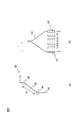
- FIG. 2 is a schematic diagram showing the segment coil 30.
- FIG. 2A is a diagram showing the shape of the segment coil 30, and
- FIG. 2B is a diagram showing two segment coils 30 inserted into the slot 21.
- the segment coil 30 is used by bending a linear coil as shown in FIG. 2A.
- Each segment coil 30 has a connecting portion 31, an inserting portion 32, an oblique portion 33, a first bent portion 34, and a second bent portion 35.
- the connection portion 31 is a portion connected to another segment coil 30 at one end of the stator core 20.
- the insertion portion 32 is a portion to be inserted inside the stator core 20.
- the first bending portion 34 is a portion that bends toward the stator core 20.
- the second bent portion 35 is a portion that bends toward the connecting portion 31, and is also a portion that is closest to the connecting portion 31 among the bent portions of the segment coil 30.
- the oblique portion 33 is a portion between the first bent portion 34 and the second bent portion 35. In FIG. 2, the first bent portion 34 and the second bent portion 35 are described as connecting portions of two straight lines, but actually draw an arc.
- the length of the skewed portion 33 is referred to as a “skewed portion length” 33L.
- the segment coil 30 is connected to other adjacent segment coils 30 and the connection portions 31 to each other.
- the distance between adjacent slots 21 is called a "slot pitch" and is used as a unit of length in the present embodiment.
- the distance between the connection portion 31 and the insertion portion 32 is referred to as a “twist amount” T.
- the twist amount T of these segment coils 30 is 2.5 slot pitch.
- the segment coil 30 included in the stator 100 has one of two twist amounts T.
- the two twist amounts T are referred to as a standard twist amount Ts and an excess twist amount Tt for convenience.
- the segment coil 30 in which the twist amount T is the standard twist amount Ts is referred to as the first segment coil 30A
- the segment coil 30 in which the twist amount T is the excess twist amount Tt is referred to as the second segment coil 30B.
- the twist amount T is not the standard twist amount Ts.
- the standard twist amount Ts will be set to 2.5 slot pitch, and a specific description will be given.
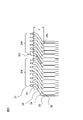
- FIG. 3 is a diagram showing a plurality of segment coils 30 straddling layers.
- FIG. 3 (a) and FIG. 3 (b) differ only in the hatch position. This hatch shows the segment coil 30 of interest.
- the hatched segment coil 30 corresponds to the second segment coil 30B when the standard twist amount Ts is 2.5 slot pitch because the insertion portions 32 are separated from each other by 6 slot pitch.
- the hatched segment coil 30 corresponds to the first segment coil 30A when the standard twist amount Ts is 2.5 slot pitch because the insertion portions 32 are separated from each other by 5 slot pitch. In this way, the first segment coil 30A and the second segment coil 30B may be mixed in the segment coil 30 straddling the layers.
- FIG. 4 is a diagram showing a connection portion of each phase.
- both phases have a second segment coil 30B at the ends of the innermost and outermost layers.
- the second segment coils 30B on the innermost circumference are connected to each other by the connecting member C to form a neutral wire.
- the second segment coil 30B on the innermost circumference of the U phase is represented by the reference numeral 30B-U
- the second segment coil 30B on the innermost circumference of the V phase is represented by the reference numeral 30B-V
- the innermost circumference of the W phase is represented by the reference numeral 30B-V.
- the second segment coil 30B of the above is represented by reference numeral 30B-W.
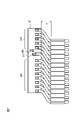
- FIG. 5 is a diagram showing the relationship between the first segment coil 30A and the second segment coil 30B.
- Most of the segment coils 30 shown in FIG. 5 are the first segment coils 30A, and only one shown in the substantially center is the second segment coil 30B.
- the insertion portion 32 is inserted into the stator core 20.
- the distance Y from the end face of the stator core 20 to the second bent portion 35 is common to the first segment coil 30A and the second segment coil 30B.
- the distance in the central axis direction of the stator core 20 from the first bent portion 34 to the second bent portion 35 in the state where the segment coil 30 is inserted into the stator core 20 is the first segment coil 30A and the first.
- the second segment coil 30B has a longer twist amount T than the first segment coil 30A. Therefore, the oblique portion length 33L of the second segment coil 30B is longer than the oblique portion length 33L of the first segment coil 30A. As shown in FIG. 4, the distance from the second bent portion 35 to the connecting portion 31 is longer in the second segment coil 30B than in the first segment coil 30A.
- FIG. 6 is a diagram showing a molding method of the segment coil 30.
- the segment coil 30 is created by the procedure shown in FIGS. 6 (a) to 6 (e) using the twisting jig J.
- the twisting jig J is a cylindrical jig in which a recess is provided at a position corresponding to each of the first segment coil 30A and the second segment coil 30B. The depth of the recess is deeper at the position corresponding to the second segment coil 30B than at the position corresponding to the first segment coil 30A.
- two second segment coils 30B are formed in the upper part of the drawing, and the first segment coil 30A is formed in all of the other parts in the upper part and the lower part in the drawing.
- the rod-shaped first segment coil 30A that becomes the first segment coil 30A by being molded is referred to as a “rod-shaped first segment coil” 130A.
- the rod-shaped second segment coil 30B that becomes the second segment coil 30B by being molded is referred to as a "rod-shaped second segment coil” 130B.
- FIG. 6A shows a state in which the insertion step is completed.
- the rod-shaped second segment coil 130B is longer than the rod-shaped first segment coil 130A.
- the twisting jig at the upper part of the drawing is moved in the direction indicated by reference numeral F1 in FIG. 6A.
- the twisting jig J is brought closer to the end face of the stator core 20 from a distance in the axial direction of the stator core 20, and only the tip of the rod-shaped second segment coil 130B is recessed in the twisting jig J. Adjust to the position where it will be inserted into.
- FIG. 6B shows a state in which the initial position adjustment step is completed.
- the relative positions of the stator core 20 and the twisting jig J are shifted by a predetermined amount in the circumferential direction, that is, twisted to form a rod-shaped second segment.
- the coil 130B is slightly deformed.
- FIG. 6 (c) shows a state in which the first twisting step is completed.
- the twisting jig J is brought closer to the end face of the stator core 20 from a distance in the axial direction of the stator core 20 to form a rod.
- FIG. 6D shows a state in which the final position adjustment step is completed.
- the relative positions of the stator core 20 and the twisting jig J are shifted by a predetermined amount in the circumferential direction, that is, twisted.
- the rod-shaped first segment coil 130A and the rod-shaped second segment coil 130B are deformed to form the first segment coil 30A and the second segment coil 30B.
- the segment coil 30 is formed by the above processing.
- the stator 100 is used for a rotary electric machine.
- the stator 100 includes a cylindrical stator core 20 in which a plurality of slots 21 are formed, and a plurality of segment coils 30 inserted into the slots 21 in layers along the radial direction of the stator core 20. ..
- the segment coil 30 faces the stator core 20 between the connection portion 31 connected to the other segment coil 30 and the insertion portion 32 arranged inside the stator core 20.
- the first bent portion 34 to be bent, the second bent portion 35 which is a bent portion formed on the side closest to the connecting portion 31, and the oblique portion between the first bent portion 34 and the second bent portion 35. 33, is formed.
- the stator 100 includes a first segment coil 30A located on a predetermined layer of the layers and a second segment coil 30B located on the same layer as the first segment coil 30A.
- the distance from the end face of the stator core 20 in the second segment coil 30B to the second bent portion 35 is from the end face of the stator core 20 in the first segment coil 30A to the second bent portion 35. It is Y which is the same as the distance of.
- the length of the skew portion 33 in the second segment coil 30B is different from the length of the skew portion 33 in the first segment coil 30A. Therefore, a plurality of segment coils 30 having different twist amounts T can be manufactured in one step, and productivity can be improved.
- the slanted portion 33 of the second segment coil 30B is formed longer than the slanted portion 33 of the first segment coil 30A.
- the length between the second bent portion 35 and the connecting portion 31 in the second segment coil 30B is formed longer than the length between the second bent portion and the connecting portion in the first segment coil. Therefore, it is not necessary to process only the tip portion of the second segment coil 30B, and the segment coil 30 can be molded with only one twisting jig J.
- the first segment coil 30A is connected to the segment coil 30 arranged in the adjacent layer.
- the second segment coil 30B constitutes a neutral wire by being connected to another segment coil 30 via the connecting member C. Therefore, since the position of the connecting portion 31 of the second segment coil 30B can be adjusted according to the shape of the neutral wire to be connected, the degree of freedom in designing the shape of the neutral wire is increased.
- the layer to which the first segment coil 30A and the second segment coil 30B belong is at least one layer of the innermost peripheral layer and the outermost outer peripheral layer of the stator 100. Therefore, since the connecting portion 31 is located on the innermost circumference or the outermost circumference, there is a margin of space, welding of the connecting portion 31 is facilitated, and the coil end can be kept low.
- the number of the second segment coil 30B is smaller than that of the first segment coil 30A.
- the second segment coil 30B is formed so that the length between the second bent portion 35 and the connecting portion 31 is longer than the length between the second bent portion 35 and the connecting portion 31 of the first segment coil 30A. Therefore, the number of segment coils 30 in which the second segment coil 30B is first inserted into the twisting jig J is small, and the productivity is improved. If the number of the second segment coil 30B is larger than that of the first segment coil 30A, more than half of the ends of the segment coil 30 will be inserted into the groove of the twisting jig J in the initial position adjustment step. Therefore, selection is complicated and inefficient.
- the method for manufacturing the stator 100 includes the following first to fourth steps.
- the first step is the above-mentioned insertion step, in which the first segment coil 30A and the second segment coil 30B having a longer axial length of the stator core 20 than the first segment coil 30A are inserted into the slot 21.
- the second step is the above-mentioned initial position adjustment step, which is a step of bringing the twisting jig J into contact with the second segment coil 30B.
- the third step is the first twisting step described above, and is a step of tilting the second segment coil 30B in the circumferential direction of the stator core 20 by moving the twisting jig J in the circumferential direction of the stator core 20.
- the fourth step is the final position adjustment step described above, and by moving the twisting jig J in the axial direction of the stator core 20, the first segment coil 30A is used as the twisting jig J in addition to the second segment coil 30B. This is the process of contacting.
- the fourth step is the final twisting step described above, and is a step of tilting the first segment coil 30A and the second segment coil 30B in the circumferential direction by moving the twisting jig J in the circumferential direction. Therefore, the segment coil 30 can be formed in one step by appropriately moving the twisting jig J.
- the second segment coil 30B has a longer skew portion length 33L than the first segment coil 30A, and the distance from the second bending portion 35 to the connection portion 31 is longer.
- the second segment coil 30B may have a shorter oblique portion length 33L than the first segment coil 30A, and the distance from the second bent portion 35 to the connecting portion 31 may be shorter.
- the tip of the rod-shaped second segment coil 130B may be bent in advance and then inserted into the slot 21 to execute the final position adjusting step and the final twisting step without going through the initial position adjusting step and the initial twisting step.
- the twist amount T of the first segment coil 30A that is, the standard twist amount Ts is 2.5 slot pitch
- the twist amount T of the second segment coil 30B that is, the excess twist amount Tt is 3.0 slot pitch. Illustrated as.
- the standard twist amount Ts is a multiple of 0.5 slot pitch.
- the excess twist amount Tt does not have to be a multiple of 0.5 slot pitch because only one end is inserted into the slot 21 especially when it is set at the end.
- FIG. 7 is a diagram showing a segment coil 30 in the second embodiment.
- the segment coil 30 includes a third segment coil 30C.
- the twist amount T and the length of the skew portion 33 of the third segment coil 30C are longer than those of the second segment coil 30B. That is, the twist amount T and the skew portion length 33L become longer in the order of the first segment coil 30A, the second segment coil 30B, and the third segment coil 30C.
- the distance from the end face of the stator core 20 to the second bent portion 35 is the same for all of the first segment coil 30A, the second segment coil 30B, and the third segment coil 30C.
- the second segment coil 30B is arranged between the first segment coil 30A and the third segment coil 30C.
- the rod-shaped third segment coil 30C that becomes the third segment coil 30C by being molded is referred to as a “rod-shaped third segment coil” 130C.
- the rod-shaped third segment coil 130C is shorter than the rod-shaped second segment coil 130B and longer than the rod-shaped first segment coil 130A.
- the method for manufacturing the segment coil 30 in the present embodiment is significantly different from the first embodiment in that a second position adjusting step and a second twisting step are included between the first twisting step and the final position adjusting step.
- the twisting jig J2 used in the present embodiment is a cylindrical jig having recesses at positions corresponding to the first segment coil 30A, the second segment coil 30B, and the third segment coil 30C, respectively. As shown in FIG. 7, the depth of the recess of the twisting jig J2 is deeper at the position corresponding to the third segment coil 30C than at the position corresponding to the first segment coil 30A, and corresponds to the second segment coil 30B. The position to do is the deepest.
- the rod-shaped segment coil 30 inserted at this time is different from the first embodiment in that the rod-shaped third segment coil 130C is included.
- the initial position adjustment step and the initial twisting step are the same as those in the first embodiment. That is, in the first twisting step, only the longest rod-shaped second segment coil 130B is machined.
- the twisting jig J is brought closer to the end face of the stator core 20 from a distance in the axial direction of the stator core 20, and the tip of the rod-shaped third segment coil 130C is twisted in addition to the rod-shaped second segment coil 130B. Adjust the position so that it is inserted into the recess of the jig J.
- the relative positions of the stator core 20 and the twisting jig J are shifted by a predetermined amount in the circumferential direction, that is, twisted to deform the rod-shaped second segment coil 130B and the rod-shaped third segment coil 130C.
- the next final position adjustment step is the same as that of the first embodiment. Adjust the tip to the position where it is inserted into the recess of the twisting jig J.
- the final final twisting step is the same as that of the first embodiment, and the relative positions of the stator core 20 and the twisting jig J are shifted by a predetermined amount in the circumferential direction, that is, the shapes of all the segment coils 30 are formed by twisting. To process.
- a third segment coil 30C having an oblique portion 33 longer than the oblique portion 33 in the second segment coil 20B is provided.
- the second segment coil 30B is arranged between the first segment coil 30A and the third segment coil 30C. Therefore, even if the variation of the segment coil 30 is increased, the segment coil 30 can be molded in one step as in the first embodiment.
Landscapes
- Engineering & Computer Science (AREA)
- Power Engineering (AREA)
- Manufacturing & Machinery (AREA)
- Windings For Motors And Generators (AREA)
- Manufacture Of Motors, Generators (AREA)
Abstract
Description
本発明の第2の態様による回転電機の固定子の製造方法は、複数のスロットが形成される固定子コアと、前記固定子コアの径方向に沿ってレイヤをなして前記スロットに挿入される複数のセグメントコイルと、を備える回転電機の固定子の製造方法であって、第1セグメントコイルと前記第1セグメントコイルより回転電機の軸方向長さが大きく形成される第2セグメントコイルとを前記スロットに挿入する第1工程と、前記第2セグメントコイルに治具を接触させる第2工程と、前記治具を前記固定子コアの周方向に移動させることで、前記第2セグメントコイルを前記固定子コアの周方向に傾ける第3工程と、前記治具を前記固定子コアの軸方向に移動させることで、前記第2セグメントコイルに加えて前記第1セグメントコイルを前記治具に接触させる第4工程と、前記治具を前記固定子コアの周方向に移動させることで、前記第1セグメントコイルおよび前記第2セグメントコイルを周方向に傾ける第5工程と、を含む。
以下、図1~図6を参照して、回転電機の固定子、および回転電機の固定子の製造方法の第1の実施の形態を説明する。
(1)固定子100は回転電機に用いられる。固定子100は、複数のスロット21が形成される円筒形の固定子コア20、および固定子コア20の径方向に沿ってレイヤをなしてスロット21に挿入される複数のセグメントコイル30、を備える。固定子コア20の一端において、セグメントコイル30は、他のセグメントコイル30と接続される接続部31と固定子コア20の内部に配置される挿入部32との間に、固定子コア20に向かって屈曲する第1屈曲部34、接続部31に最も近い側に形成される屈曲する部位である第2屈曲部35、および第1屈曲部34と第2屈曲部35との間の斜行部33、が形成される。固定子100は、レイヤのうち所定レイヤに位置する第1セグメントコイル30Aと、第1セグメントコイル30Aと同じレイヤに位置する第2セグメントコイル30Bと、を含む。図5に示したように、第2セグメントコイル30Bにおける固定子コア20の端面から第2屈曲部35までの距離は、第1セグメントコイル30Aにおける固定子コア20の端面から第2屈曲部35までの距離と同一のYである。第2セグメントコイル30Bにおける斜行部33の長さは、第1セグメントコイル30Aにおける斜行部33の長さとは異なる。そのため、捻り量Tが異なる複数のセグメントコイル30を一工程で製造することができ、生産性を向上させることができる。
上述した実施の形態では、第2セグメントコイル30Bは第1セグメントコイル30Aよりも斜行部長33Lが長く、かつ第2屈曲部35から接続部31までの距離が長かった。しかし第2セグメントコイル30Bは、第1セグメントコイル30Aよりも斜行部長33Lが短く、かつ第2屈曲部35から接続部31までの距離が短くてもよい。
棒状第2セグメントコイル130Bの先端にあらかじめ曲げ加工を施してからスロット21に挿入し、初回位置調整ステップおよび初回捻りステップを経ることなく最終位置調整ステップおよび最終捻りステップを実行してもよい。
上述した実施の形態では、第1セグメントコイル30Aの捻り量T、すなわち標準捻り量Tsを2.5スロットピッチ、第2セグメントコイル30Bの捻り量T、すなわち超過捻り量Ttを3.0スロットピッチとして例示した。2つの第1セグメントコイル30Aが接続されることで、いずれかのスロット21から他のスロット21に出入りをするので、標準捻り量Tsは0.5スロットピッチの倍数となる。しかし超過捻り量Ttは、特に端部に設定される場合には一端しかスロット21に挿入されないので、0.5スロットピッチの倍数でなくてもよい。
図7を参照して、回転電機の固定子、および回転電機の固定子の製造方法の第2の実施の形態を説明する。以下の説明では、第1の実施の形態と同じ構成要素には同じ符号を付して相違点を主に説明する。特に説明しない点については、第1の実施の形態と同じである。本実施の形態では、主に、セグメントコイルの形状のバリエーションがもう1つ追加される点で、第1の実施の形態と異なる。
以下では、成型されることで第3セグメントコイル30Cとなる棒状の第3セグメントコイル30Cを、「棒状第3セグメントコイル」130Cと呼ぶ。棒状第3セグメントコイル130Cは、棒状第2セグメントコイル130Bよりも短く、棒状第1セグメントコイル130Aよりも長い。以下では主に第1の実施の形態における製造方法との相違点を説明する。本実施の形態におけるセグメントコイル30の製造方法は、初回捻りステップと最終位置調整ステップとの間に二回目位置調整ステップおよび二回目捻りステップを含む点が第1の実施の形態と大きく異なる。
(7)第2セグメントコイル20Bにおける斜行部33よりも長い斜行部33を有する第3セグメントコイル30Cを備える。所定のレイヤにおいて、第2セグメントコイル30Bは、第1セグメントコイル30Aと第3セグメントコイル30Cの間に配置される。そのため、セグメントコイル30のバリエーションを増やしても第1の実施の形態と同様に一工程でセグメントコイル30を成型できる。
21…スロット
30…セグメントコイル
30A…第1セグメントコイル
30B…第2セグメントコイル
30C…第3セグメントコイル
130A…棒状第1セグメントコイル
130B…棒状第2セグメントコイル
130C…棒状第3セグメントコイル
31…接続部
32…挿入部
33…斜行部
33L…斜行部長
34…第1屈曲部
35…第2屈曲部
100…固定子
C…接続部材
J、J2…ひねり治具
Claims (7)
- 複数のスロットが形成される円筒形の固定子コア、および前記固定子コアの径方向に沿ってレイヤをなして前記スロットに挿入される複数のセグメントコイル、を備える回転電機の固定子であって、
前記固定子コアの一端において、前記セグメントコイルは、他のセグメントコイルと接続される接続部と前記固定子コアの内部に配置される挿入部との間に、
前記固定子コアに向かって屈曲する第1屈曲部、
前記接続部に最も近い側に形成される第2屈曲部、
および前記第1屈曲部と前記第2屈曲部との間の斜行部、が形成され、
前記レイヤのうち所定レイヤに位置する第1セグメントコイルと、
前記第1セグメントコイルと同じレイヤに位置する第2セグメントコイルと、を含み、
前記第2セグメントコイルにおける前記固定子コアの端面から前記第2屈曲部までの距離は、前記第1セグメントコイルにおける前記固定子コアの端面から前記第2屈曲部までの距離と同一であり、
前記第2セグメントコイルにおける前記斜行部の長さは、前記第1セグメントコイルにおける前記斜行部の長さとは異なる、回転電機の固定子。 - 請求項1に記載の回転電機の固定子であって、
前記第2セグメントコイルの前記斜行部は、前記第1セグメントコイルの前記斜行部よりも長く形成され、
前記第2セグメントコイルにおける前記第2屈曲部と前記接続部の間の長さが、前記第1セグメントコイルにおける前記第2屈曲部と前記接続部の間の長さよりも長く形成される、回転電機の固定子。 - 請求項2に記載の回転電機の固定子であって、
前記第1セグメントコイルは、隣接する前記レイヤに配置される前記セグメントコイルと接続され、
前記第2セグメントコイルは、接続部材を介して他のセグメントコイルと接続されることにより中性線を構成する、回転電機の固定子。 - 請求項3に記載の回転電機の固定子であって、
前記第2セグメントコイルにおける前記斜行部よりも長い前記斜行部を有する第3セグメントコイルをさらに備え、
前記所定レイヤにおいて、前記第2セグメントコイルは、前記第1セグメントコイルと前記第3セグメントコイルの間に配置される回転電機の固定子。 - 請求項3に記載の回転電機の固定子であって、
前記所定レイヤは、当該固定子の最内周のレイヤおよび最外周のレイヤの少なくとも一方のレイヤである回転電機の固定子。 - 請求項1に記載の回転電機の固定子であって、
前記第2セグメントコイルは、第1セグメントコイルよりも本数が少なく、
第2屈曲部と前記接続部の間の長さが、前記第1セグメントコイルの第2屈曲部と前記接続部の間の長さよりも長く形成される、回転電機の固定子。 - 複数のスロットが形成される固定子コアと、前記固定子コアの径方向に沿ってレイヤをなして前記スロットに挿入される複数のセグメントコイルと、を備える回転電機の固定子の製造方法であって、
第1セグメントコイルと前記第1セグメントコイルより回転電機の軸方向長さが大きく形成される第2セグメントコイルとを前記スロットに挿入する第1工程と、
前記第2セグメントコイルに治具を接触させる第2工程と、
前記治具を前記固定子コアの周方向に移動させることで、前記第2セグメントコイルを前記固定子コアの周方向に傾ける第3工程と、
前記治具を前記固定子コアの軸方向に移動させることで、前記第2セグメントコイルに加えて前記第1セグメントコイルを前記治具に接触させる第4工程と、
前記治具を前記固定子コアの周方向に移動させることで、前記第1セグメントコイルおよび前記第2セグメントコイルを周方向に傾ける第5工程と、を含む回転電機の固定子の製造方法。
Priority Applications (2)
| Application Number | Priority Date | Filing Date | Title |
|---|---|---|---|
| JP2022566761A JP7490818B2 (ja) | 2020-12-01 | 2021-08-31 | 回転電機の固定子、回転電機の固定子の製造方法 |
| CN202180079443.2A CN116615856A (zh) | 2020-12-01 | 2021-08-31 | 旋转电机定子、旋转电机定子的制造方法 |
Applications Claiming Priority (2)
| Application Number | Priority Date | Filing Date | Title |
|---|---|---|---|
| JP2020199634 | 2020-12-01 | ||
| JP2020-199634 | 2020-12-01 |
Publications (1)
| Publication Number | Publication Date |
|---|---|
| WO2022118508A1 true WO2022118508A1 (ja) | 2022-06-09 |
Family
ID=81854050
Family Applications (1)
| Application Number | Title | Priority Date | Filing Date |
|---|---|---|---|
| PCT/JP2021/032023 Ceased WO2022118508A1 (ja) | 2020-12-01 | 2021-08-31 | 回転電機の固定子、回転電機の固定子の製造方法 |
Country Status (3)
| Country | Link |
|---|---|
| JP (1) | JP7490818B2 (ja) |
| CN (1) | CN116615856A (ja) |
| WO (1) | WO2022118508A1 (ja) |
Citations (5)
| Publication number | Priority date | Publication date | Assignee | Title |
|---|---|---|---|---|
| JP2016052234A (ja) * | 2014-09-02 | 2016-04-11 | トヨタ自動車株式会社 | リード線付回転電機ステータの製造方法 |
| WO2018233988A1 (de) * | 2017-06-23 | 2018-12-27 | Strama-Mps Maschinenbau Gmbh & Co. Kg | Vorrichtung und verfahren zum bearbeiten mindestens eines leitersegments eines wicklungsträgers einer elektrischen maschine |
| WO2020022338A1 (ja) * | 2018-07-23 | 2020-01-30 | 株式会社小田原エンジニアリング | コイルの端子接続方法、ツイスト治具及び回転電機のステータ |
| WO2020140504A1 (zh) * | 2018-12-30 | 2020-07-09 | 苏州阿福机器人有限公司 | 一种用于扁线电机绕组中扁线折弯的装置 |
| WO2021149624A1 (ja) * | 2020-01-22 | 2021-07-29 | 株式会社小田原エンジニアリング | コイルセグメントのツイスト方法、ツイスト治具及びツイスト装置 |
Family Cites Families (3)
| Publication number | Priority date | Publication date | Assignee | Title |
|---|---|---|---|---|
| JP6098589B2 (ja) * | 2014-08-08 | 2017-03-22 | トヨタ自動車株式会社 | 回転電機ステータ |
| JP6862715B2 (ja) * | 2016-08-10 | 2021-04-21 | 富士電機株式会社 | 固定子及びそれを備えた回転電機 |
| JP2020048359A (ja) * | 2018-09-20 | 2020-03-26 | トヨタ自動車株式会社 | ステータの製造方法 |
-
2021
- 2021-08-31 WO PCT/JP2021/032023 patent/WO2022118508A1/ja not_active Ceased
- 2021-08-31 CN CN202180079443.2A patent/CN116615856A/zh active Pending
- 2021-08-31 JP JP2022566761A patent/JP7490818B2/ja active Active
Patent Citations (5)
| Publication number | Priority date | Publication date | Assignee | Title |
|---|---|---|---|---|
| JP2016052234A (ja) * | 2014-09-02 | 2016-04-11 | トヨタ自動車株式会社 | リード線付回転電機ステータの製造方法 |
| WO2018233988A1 (de) * | 2017-06-23 | 2018-12-27 | Strama-Mps Maschinenbau Gmbh & Co. Kg | Vorrichtung und verfahren zum bearbeiten mindestens eines leitersegments eines wicklungsträgers einer elektrischen maschine |
| WO2020022338A1 (ja) * | 2018-07-23 | 2020-01-30 | 株式会社小田原エンジニアリング | コイルの端子接続方法、ツイスト治具及び回転電機のステータ |
| WO2020140504A1 (zh) * | 2018-12-30 | 2020-07-09 | 苏州阿福机器人有限公司 | 一种用于扁线电机绕组中扁线折弯的装置 |
| WO2021149624A1 (ja) * | 2020-01-22 | 2021-07-29 | 株式会社小田原エンジニアリング | コイルセグメントのツイスト方法、ツイスト治具及びツイスト装置 |
Also Published As
| Publication number | Publication date |
|---|---|
| JP7490818B2 (ja) | 2024-05-27 |
| JPWO2022118508A1 (ja) | 2022-06-09 |
| CN116615856A (zh) | 2023-08-18 |
Similar Documents
| Publication | Publication Date | Title |
|---|---|---|
| KR101044175B1 (ko) | 모터 고정자를 제조하는 방법 및 모터 고정자 | |
| JP5573327B2 (ja) | 回転電機の固定子及びその製造方法 | |
| JP5557058B2 (ja) | 回転電機の固定子及びその製造方法 | |
| US7923884B2 (en) | Rotary electric machine having stator coil with U-shaped segment | |
| JP7255556B2 (ja) | 車両用回転電機のステータの製造方法 | |
| US20180076673A1 (en) | Stator and motor having the same | |
| JP7038894B2 (ja) | 回転電機のステータ、回転電機、回転電機のステータの製造方法、および、回転電機の製造方法 | |
| KR20030087062A (ko) | 내전형 전동기의 고정자 및 그 제조방법 | |
| JP2018088729A (ja) | 回転電機のステータ | |
| JP6334365B2 (ja) | 回転電機の製造方法 | |
| JP2020110025A (ja) | セグメントコイル成形方法 | |
| CN102545410A (zh) | 加工用于电机的机器构件的构件 | |
| JP6351861B2 (ja) | 電機子の製造方法 | |
| JP2010268575A (ja) | 回転電機 | |
| US20240313605A1 (en) | Brushless motor | |
| JP2013118764A (ja) | ステータ製造方法及びステータ製造装置 | |
| JP7490818B2 (ja) | 回転電機の固定子、回転電機の固定子の製造方法 | |
| CN116526708B (zh) | 一种定子铁芯、定子、电机及制造工艺 | |
| JP7721981B2 (ja) | 回転電機用ステータ | |
| JP4483241B2 (ja) | 3相モータ | |
| JP7270846B2 (ja) | 回転電機のステータ、回転電機、回転電機のステータの製造方法、および回転電機の製造方法 | |
| CN119769007A (zh) | 定子的制造方法及定子的制造装置 | |
| JP2006353038A (ja) | 電機子、ブラシレスモータ、及び電機子の巻線方法 | |
| JP2011172440A (ja) | 回転電機のステータ | |
| JP7246224B2 (ja) | 回転電機 |
Legal Events
| Date | Code | Title | Description |
|---|---|---|---|
| 121 | Ep: the epo has been informed by wipo that ep was designated in this application |
Ref document number: 21900264 Country of ref document: EP Kind code of ref document: A1 |
|
| ENP | Entry into the national phase |
Ref document number: 2022566761 Country of ref document: JP Kind code of ref document: A |
|
| WWE | Wipo information: entry into national phase |
Ref document number: 202180079443.2 Country of ref document: CN |
|
| NENP | Non-entry into the national phase |
Ref country code: DE |
|
| 122 | Ep: pct application non-entry in european phase |
Ref document number: 21900264 Country of ref document: EP Kind code of ref document: A1 |