WO2021149624A1 - コイルセグメントのツイスト方法、ツイスト治具及びツイスト装置 - Google Patents
コイルセグメントのツイスト方法、ツイスト治具及びツイスト装置 Download PDFInfo
- Publication number
- WO2021149624A1 WO2021149624A1 PCT/JP2021/001379 JP2021001379W WO2021149624A1 WO 2021149624 A1 WO2021149624 A1 WO 2021149624A1 JP 2021001379 W JP2021001379 W JP 2021001379W WO 2021149624 A1 WO2021149624 A1 WO 2021149624A1
- Authority
- WO
- WIPO (PCT)
- Prior art keywords
- twist
- tip portion
- accommodating recess
- jig
- coil segment
- Prior art date
Links
Images


Classifications
-
- H—ELECTRICITY
- H02—GENERATION; CONVERSION OR DISTRIBUTION OF ELECTRIC POWER
- H02K—DYNAMO-ELECTRIC MACHINES
- H02K15/00—Methods or apparatus specially adapted for manufacturing, assembling, maintaining or repairing of dynamo-electric machines
- H02K15/0056—Manufacturing winding connections
- H02K15/0068—Connecting winding sections; Forming leads; Connecting leads to terminals
- H02K15/0081—Connecting winding sections; Forming leads; Connecting leads to terminals for form-wound windings
- H02K15/0087—Connecting winding sections; Forming leads; Connecting leads to terminals for form-wound windings characterised by the method or apparatus for simultaneously twisting a plurality of hairpins open ends after insertion into the machine
-
- H—ELECTRICITY
- H02—GENERATION; CONVERSION OR DISTRIBUTION OF ELECTRIC POWER
- H02K—DYNAMO-ELECTRIC MACHINES
- H02K15/00—Methods or apparatus specially adapted for manufacturing, assembling, maintaining or repairing of dynamo-electric machines
- H02K15/08—Forming windings by laying conductors into or around core parts
- H02K15/085—Forming windings by laying conductors into or around core parts by laying conductors into slotted stators
Definitions
- the present invention relates to a method of twisting a coil segment in a stator of a rotary electric machine such as a motor or a generator, and a twist jig and a twist device used for twisting the coil segment.
- a so-called segment type coil is known as a stator coil in a rotating electric machine such as a motor or a generator.
- This segment type coil has a plurality of U-shaped coil segments having a pair of linearly extending slot insertion portions in a plurality of slots arranged along the circumferential direction of a stator core (hereinafter abbreviated as a core).
- a plurality of layers are formed in the radial direction of the core by inserting so as to straddle between the coils, and the tip portion in the insertion direction protruding from the core end face of these coil segments is twisted in the opposite direction for each layer in the radial direction of the core.
- the tips of adjacent layers are electrically joined by welding or the like.
- the U-shaped coil segment is also called a hairpin. Twisting shall include the concepts of twisting and bending, and will be abbreviated as twisting below.
- Some of the above coil segments are lead wires such as input wires and neutral wires, which protrude from the end face of the core more than the normal coil segments in which the tips are joined to each other. It is a deformed coil segment with a large length.
- the tip of a normal coil segment and the tip of a deformed coil segment located in the same layer as the normal coil segment are the same twist jig. By the rotation of the twisting jig, each layer is twisted in the same circumferential direction and in the opposite direction to the coil segments of adjacent layers in the radial direction.
- the position of the tip of the deformed coil segment after twisting in the circumferential direction of the core is the same as the position of the tip of the normal coil segment. That is, the joint row at the tip of the normal coil segment and the tip of the deformed coil segment are aligned in the radial direction of the core.
- a lead wire formed by a deformed coil segment located in the innermost layer (innermost layer) of the core is electrically connected to a terminal member arranged on the outer side in the radial direction.
- the coil segment When connecting, the coil segment must be connected so as to straddle the upper part of the joint row at the tip of the coil segment.
- the coil described in Patent Document 1 is not configured to insert a U-shaped coil, but as is clear from FIG. 17B, the end of the coil is bent in the radial direction of the core to reduce the size. The above method is adopted for.
- connection configuration in which the lead wire straddles the upper part of the joint row as described above, it is necessary to increase the length of the lead portion of the deformed coil segment, and the material cost of the coil segment formed of copper, aluminum, etc. is increased accordingly. It leads to an increase.
- the smaller the amount of protrusion of the coil from the core end face the more it contributes to the miniaturization of the motor or the like, which affects the miniaturization in millimeters.
- the rising height of the lead wire is large, the rigidity of the connection portion between the lead wire and the terminal member also decreases, so that the natural frequency of the lead wire decreases. For this reason, for example, there is a concern that it resonates with the vibration accompanying the rotation of the vehicle engine and causes disconnection stress in the connection portion.
- the present invention has been made in view of such a situation, and in a rotary electric machine stator using a coil segment, the cost of the connection portion between the coil segment and the terminal member is reduced and the rigidity is improved.
- the purpose is to contribute to the miniaturization of rotary electric machines.
- a plurality of coil segments are inserted into a plurality of slots arranged in the circumferential direction of the core that should form the stator of the rotary electric machine.
- the tip of each coil segment protruding from the end face of the core toward the insertion direction of the insertion forms a plurality of layers in the radial direction of the core, and one layer of the plurality of layers, the other.
- the tall tip portions is placed in the second accommodating recess of the twist jig provided with the first accommodating recess for accommodating the short tip portion and the second accommodating recess for accommodating the tall tip portion.
- the tall portion is inserted into the second accommodating recess.
- a secondary twist is performed in which the twist jig is rotated more than the predetermined amount.
- the plurality of coil segments are arranged so that the tall tip portion is arranged at a position between the adjacent short tip portions when viewed in the circumferential direction by the primary twist and the secondary twist. Twist the tip of the coil segment of.
- the first one before performing the primary twist, the first one is in a state where at least a part of the tall tip portion is inserted into each of the second accommodating recesses of the twist jig.
- the accommodating recess is located at a position deviated from the short tip portion to be accommodated in the first accommodating recess in the circumferential direction, and after the primary twist is performed, the first accommodating recess is the first accommodating recess. It is preferable to come to a position substantially opposite to the short tip portion to be accommodated in the recess.
- the layer on which the tall tip portion is arranged may be the innermost layer or the outermost layer in the radial direction.
- the amount of rotation of the twist jig in the primary twist is approximately 1/2 of the formation pitch of the slot
- the amount of rotation of the twist jig in the secondary twist is the formation pitch of the slot. It is good that it is 1 times or more of.
- the secondary twist may be performed in the opposite direction to the primary twist.
- the present invention can be carried out as a method as described above, or as a twist jig or a twist device suitable for carrying out the twist method described above. It is not hindered from the operation method of the twist device, the program used for controlling the twist device, and the implementation as a recording medium in which the program is stored.
- FIG. 3 is a schematic cross-sectional view taken along the line IV-IV of FIG.
- FIG. 3 is a schematic block diagram of the twist device which is one Embodiment of this invention. It is an exploded perspective view of the twist jig in the twist device of FIG. FIG.
- FIG. 6 is a schematic cross-sectional view of the inner twist jig 26 along the line VII-VII of FIG. It is a figure for demonstrating the twist operation by the twist device shown in FIG. 5, and is the figure developed linearly which shows the positional relationship between the coil segment before twisting, and the accommodating recess of the inner twist jig. It is a figure corresponding to FIG. 8A which shows the positional relationship between the coil segment before twisting and the accommodating recess of the inner twist jig at a position different from FIG. 8A. It is a figure corresponding to FIG. 8A which shows the positional relationship between a coil segment and an inner twist jig at the start of a twist operation.
- FIG. 8C It is a figure which shows the state which the tip part of the deformed coil segment is partially inserted into the 2nd accommodating recess from the state shown in FIG. 8C. It is a figure which shows the state which performed the primary twist by rotating the inner twist jig from the state shown in FIG. 8D. It is a figure which shows the state which inserted the tip part of the normal coil segment into the 1st accommodating recess from the state shown in FIG. 8E. It is a figure which shows the state which performed the secondary twist from the state shown in FIG. 8F. It is a main part perspective view of a core and a coil segment which shows the lead-out wire for input at the time of finishing a secondary twist.
- FIG. 10A It is a schematic diagram for demonstrating the process of bending the input leader wire after the secondary twist, and is the figure which shows the state of the input leader wire at the time when the secondary twist is finished. It is a figure which shows the state which finished bending after FIG. 10A. It is a figure corresponding to FIG. 8A which shows the positional relationship between the coil segment before twisting and the accommodating recess of the inner twist jig in the twist jig of a modification. It is a figure corresponding to FIG. 8D for demonstrating the twist operation in the modification.
- FIG. 1 is a perspective view of the stator.
- the stator 2 shown in FIG. 1 has a plurality of cylindrical cores 6 having a plurality of slots 4 arranged in the circumferential direction, and a plurality of U-shaped coil segments (segment conductors) straddling the slots 4 in the slots 4. It includes a three-phase (U-phase, V-phase, W-phase) coil 8 configured by inserting and connecting those coil segments.
- Reference numeral 5 indicates an insulating sheet for insulating between the core 6 and the coil segment. In the following description, the reference numerals including "U” indicate the configuration related to the U-phase coil. The same applies to "V" and "W”.
- Each coil segment is inserted into the slot 4 from the lower side in the axial direction of the core 6 in the drawing, and the portion protruding from the end surface of the upper side (input side or power feeding side) in the axial direction of the core 6 in the drawing is the core 6 by a twist jig described later. It is bent in the circumferential direction of. Bending (twisting) is performed in the opposite direction for each layer adjacent to each other in the radial direction of the core 6, and after twisting, the tip portions of the coil segments facing each other in the layers adjacent to each other in the radial direction are electrically joined to each other.
- the joining portion 10 has a configuration in which the tip portions face each other (strictly speaking, a configuration in which the portions from which the insulating coating is removed from the tip of the coil segment face each other). It is called.
- slot insertion portions (described later) of six coil segments are inserted into each slot 4. Since the thicknesses of the coil segments are all the same, the radial arrangement of the six slot insertion portions inserted into one slot 4 is common to all the slots. Therefore, the six slot insertion portions inserted into one slot can be regarded as forming six layers stacked from the outermost peripheral side to the innermost peripheral side, and when referred to as "layer" in the present specification. Shall mean the layer of this slot insertion portion unless otherwise specified.
- the core 6 has a structure in which thin-walled annular electromagnetic steel sheets formed by punching or etching are laminated in the direction of the cylindrical axis and integrated.
- a plurality of teeth (magnetic pole teeth) 7 protruding toward the center are formed radially at predetermined intervals in the circumferential direction.
- the inner peripheral surface of the core 6 is generally formed by the surface on the tip side of each tooth 7, but the surface on the tip side of each tooth 7 is separated from each other.
- a part of the figure is painted white in order to make it easier to see the reference numerals near the center of FIG. 1, but the teeth 7 are separated from each other even in the filled portion. Further, a slot 4 is formed between the adjacent teeth 7.
- the number of poles (number of magnetic poles) of the rotor (not shown) inserted into the stator 2 of the present embodiment is 8, and the number of slots per phase of the three-phase coil 8 with respect to the number of poles 8 is 2. Therefore, a total of 48 slots 4 are arranged in the core 6.
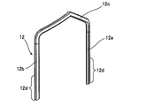
- FIG. 2A shows an example of the coil segment.
- Each coil segment is formed by bending a flat wire whose surface is covered with an insulating film into a U shape by bending.
- each of the coil segments 12 includes a pair of slot insertion portions 12a and 12b extending linearly, and a connecting portion 12c connecting them, and one slot insertion portion 12a and the coil segment 12
- the connecting portion 12c has a stepped shape so that the other slot insertion portion 12b can be arranged in different layers.
- Reference numeral 12d indicates a range of protrusion from the end face of the core 6 when the coil segment 12 is inserted into the core 6. Further, in the portion of each slot insertion portion 12a, 12b on the tip end side in the insertion direction (a range narrower than the range indicated by reference numeral 12d), the insulating coating is removed, and the slot insertion portion and the connection of other coil segments are connected. It can be electrically connected to terminals and the like.
- the coil segment of the present embodiment includes slot insertion portions 12a and 12b having the same length as shown in FIG. 2A, which have a tip portion connected to another coil segment at the joint portion 10 as shown in FIG.
- a deformed coil segment 14 including a slot insertion portion having a longer protrusion length from the end face of the core 6 than the coil segment 12 and similarly from the end face of the core 6 than the coil segment 12.
- a coil segment 16 having a tip portion having a protrusion length longer than that of the coil segment 12 and a neutral wire is included.
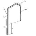
- FIG. 2B shows an example of the deformed coil segment 14.
- This irregularly shaped coil segment 14 is also composed of a pair of slot insertion portions 14a and 14b extending linearly and a connecting portion 14c connecting them, and the connecting portion 14c has a stepped shape (crank shape) for layer change. This point is common to the coil segment 12.
- one slot insertion portion 14b of the deformed coil segment 14 is longer than the other slot insertion portion 14a having the same length as the slot insertion portions 12a and 12b of the normal coil segment 12.
- the tip of the slot insertion portion 14b is longer than the tip of the slot insertion portions 12a, 12b, 14a and protrudes from the end face of the core 6, and the tip thereof serves as an input lead wire.
- Reference numeral 14d indicates a range in which the slot insertion portion 14b protrudes from the end face of the core 6 when the coil segment 14 is inserted into the core 6.
- a portion having the same length as 12d in FIG. 2A protrudes.
- the portion indicated by reference numeral 14d is referred to as a tall tip portion
- the portion indicated by reference numeral 12d is referred to as a short tip portion.
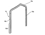
- FIG. 2C shows an example of the coil segment 16 having a tip portion that becomes a neutral line.
- the length of one slot insertion portion 16b is slightly longer than the length of the other slot insertion portion 16a.
- the normal coil segment 12 also has a protruding length from the end face of the core 6 of each slot insertion portion, corresponding to the difference in the peripheral length between the slots 4 depending on the radial position of the core 6. Depends slightly on which layer the slot insertion section forms.
- each slot insertion portion is inserted into each slot 4 so as to be arranged in a row in the radial direction of the core 6 as described above. Then, in the coils of each phase, a plurality of coil segments are connected in series by electrically connecting the slot insertion portions facing each other at the joint portion 10, and the core 6 is rotated substantially 6 times, respectively, and the arrangement position is in the circumferential direction. It has a configuration in which two coils deviated from each other are formed, and the two coils are further connected in parallel. Each coil has a structure in which the coil is routed from the innermost layer (innermost layer) toward the outermost layer (outermost layer) and returns to the innermost layer, and both ends are located in the innermost layer.
- input lead wires 14U1, 14U2, 14V1, 14V2, 14W1, 14W2 formed by bending the tall tip portion 14d of the deformed coil segment 14 are arranged in the innermost layer of the core 6. ..
- the tips of these lead wires are electrically connected to, for example, the terminal members 15U, 15V, and 15W connected to the AC output section of the inverter.
- the input lead wires 14U1 to 14W2, which are coded in FIG. 1, are located at one end of each coil.
- the terminal member 15U also serves to connect two U-phase coils in parallel. The same applies to the V phase and the W phase.
- neutral wires 16U1, 16U2, 16V1, 16V2, 16W1, 16W2 formed by the tip of the longer slot insertion portion of the coil segment 16 are also arranged, and these are used as neutral points. It is electrically connected to a long plate-shaped common conductor (not shown). The neutral wires 16U1 to 16W2 are located at the other end of each coil.
- FIG. 3 shows an enlarged main part of FIG.
- the input lead wires 14U1, 14U2, 14V1, 14V2 are provided between the joints 10 of the coil segments 12 in the circumferential direction of the core 6 (circumferential direction between the rows of the joints 10 arranged in the radial direction). It is arranged so as to lie down in the gap 21). The same applies to the input lead wires 14W1 and 14W2 that do not appear in FIG. 3 (appear in FIG. 1).
- the tip end portion of the coil segment 14 is arranged so as to lie in the gap 21 between the joint portions 10, and is led out to the other end side (outermost outer peripheral side) in the radial direction.
- the input lead wires 14U1, 14U2, 14V1, 14V2 have the tall tip portion 14d of the deformed coil segment 14 in the circumferential direction together with the short tip portion 12d of the normal coil segment 12 in the same layer.
- the bent portion 14d-1 formed by bending (twisting) in the same direction, the lead-out portion 14d-2 extending the gap 21 between the rows of the joint portions 10 from the inner peripheral side toward the outer peripheral side, and the outermost layer.
- the rising portion 14d-3 is connected to the terminal members 15U and 15V.
- the lead-out portion 14d-2 is a portion bent in the radial direction at a position corresponding to the gap 21.
- the input lead wires 14W1 and 14W2 shown in FIG. 1 have a similar configuration.
- FIG. 4 shows a schematic cross-sectional view taken along the line IV-IV of FIG.
- the input lead wire 14U1 is connected to the terminal member 15U at a short distance with a low height from the core end face. can do.
- the material cost of the coil segment is reduced as compared with the conventional configuration in which the input lead wire is raised to the position of the innermost layer and the terminal member straddles the upper part of the row of the joint 10 and is connected to the input lead wire. Can be planned.
- the height of the core 6 of the lead-out portion 14d-2 for the input wire in the axial direction can be lowered, it greatly contributes to the miniaturization of the stator 2.
- the rising length of the rising portion 14d-3 is relatively long, but in the terminal connection configuration described here, even if the rising length is shorter, the rising portion 14d-3 itself It is possible to connect the coil and the terminal member without providing the above. According to this configuration, the effect of reducing the material cost of the coil segment and reducing the size of the stator 2 can be further enhanced.
- the rigidity of the connection portion between the lead-out wire for input and the terminal member can be increased. This makes it possible to increase the natural frequency of the input lead wire. That is, if the rigidity of the connecting portion is low, the natural frequency of the input lead wire decreases, but this decrease can be suppressed. By increasing the natural frequency in this way, it is possible to reduce the risk that, for example, the connection portion resonates with the vibration accompanying the rotation of the vehicle engine and causes disconnection stress in the connection portion.
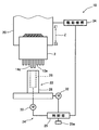
- FIG. 5 is a schematic configuration diagram of a twist device according to an embodiment of the present invention.
- the twisting device 18 inserts an appropriate coil segment into each slot 4 of the core 6 so that the stator 2 in the pre-twisted state has the protruding tip of the coil segment facing downward.
- the twist jig 22 is a coil in the innermost layer and the adjacent layer (second layer from the inner peripheral side) inserted into the plurality of slots 4 of the core 6 shown in FIG. 1 and protruding from the end surface of the core 6. This is a tool for bending the tip of the slot insertion portion of the segments 12, 14 and 16 in the insertion direction in the circumferential direction of the core 6.
- the twist jig 22 includes an inner twist jig 26 that twists the tip of the slot insertion portion arranged in the innermost layer and an outer side that twists the tip of the slot insertion portion arranged in the second layer from the inner peripheral side. It has a twist jig 28.
- the inner twist jig 26 has a diameter corresponding to the innermost layer in the radial direction in which the tall tip portion 14d constituting the slot insertion portion 14b of the deformed coil segment 14 is arranged, and the outer twist jig 28 is from the inner peripheral side. It has a diameter corresponding to the second layer.
- the rotation drive mechanism 24 includes a rotation drive mechanism that rotationally drives the inner twist jig 26 and the outer twist jig 28, respectively.
- the rotation drive mechanism drives the inner twist jig 26 by the power of the motor 30, and drives the outer twist jig 28 by the power of the motor 32.
- the motor 30 and the motor 32 are connected to the control unit 25 via a motor driver. Data such as the amount of rotation and the direction of rotation of the inner twist jig 26 and the outer twist jig 28 are stored in the non-volatile memory 25a of the control unit 25, and the control unit 25 controls the rotation drive mechanism 24 based on this data. do.
- the work holding mechanism 20 can be moved in the vertical direction (arrow Z direction) by the drive mechanism 34, and at the time of twisting, the lowering movement of the stator 2 and the rotational operation of the twist jig 22 are simultaneously performed by the control of the control unit 25.
- FIG. 6 is an exploded perspective view of the twist jig in the twist device of FIG.
- the inner twist jig 26 is formed on a cylindrical jig body 36 connected to the rotation drive mechanism 24 and an outer peripheral surface of an axially upper end portion of the jig body 36. It has one accommodating recess 38a, a second accommodating recess 38b, and a third accommodating recess 38c. A plurality of the first accommodating recesses 38a, the second accommodating recesses 38b, and the third accommodating recesses 38c are formed at intervals in the circumferential direction.
- FIG. 7 is a schematic cross-sectional view of the inner twist jig 26 along the line VII-VII of FIG.
- an insertion hole 36b into which the drive shaft of the rotation drive mechanism 24 is inserted is formed on the bottom surface 36a of the jig body 36, and a plurality of (here, four) screw holes 36c are formed in the circumferential direction. It is formed at equal intervals.
- the jig body 36 is bolted to the rotation drive mechanism 24 via these screw holes 36c.
- a stepped annular guide surface 36d for guiding the tip end portion of the slot insertion portion of each coil segment to each accommodating recess is formed.
- the first accommodating recess 38a constitutes a joint portion 10 among the slot insertion portions included in the coil segments 12, 14 and 16, and is a tip portion (short tip) of a pair of slot insertion portions to be electrically joined to each other. Part 12d) is accommodated.
- the second accommodating recess 38b accommodates the tip end portion (tall tip portion 14d) of the slot insertion portion 14b serving as the input lead wire 14U1, 14U2, 14V1, 14V2, 14W1, 14W2 of the deformed coil segment 14.
- the height of the third accommodating recess 38c in the axial direction is smaller than that of the second accommodating recess 38b and larger than that of the first accommodating recess 38a, and the tip of the longer slot insertion portion 16b of the coil segment 16 which is a neutral wire. (See FIG. 2C. Hereinafter referred to as a tip portion 16d) is accommodated.
- each tip portion to be accommodated in the first accommodating recess 38a is roughly shown from the tip of the slot insertion portion (slot insertion portion 14a in the coil segment 14) of each coil segment 12, 14 and 16. It is the range up to the portion of the core 6 rising in the axial direction in 1. This is a part of the range shown as, for example, the short tip portion 12d.
- the range of the tall tip portion 14d that is accommodated in the second accommodating recess 38b is the portion that constitutes the lead-out portion 14d-2 and the rising portion 14d-3 in FIG. 3 from the tip of the slot insertion portion 14b of each coil segment 14. The range is up to. This is part of the range shown as the tall tip 14d.
- the range of the tip portion 16d that is accommodated in the third accommodating recess 38c also conforms to these.
- the outer twist jig 28 has a cylindrical jig main body 40 and a flange portion 42 integrally formed with the jig main body 40 on the lower surface of the jig main body 40. ..
- a plurality of accommodating recesses 40a for accommodating the tip of the slot insertion portion arranged in the second layer from the inner peripheral side are formed at intervals in the circumferential direction.
- the height of each accommodating recess 40a is equivalent to that of the first accommodating recess 38a of the inner twist jig 26.
- the outer twist jig 28 is connected to the rotation drive mechanism 24 via a flange portion 42 and a gear configuration such as a worm gear.
- the inner twist jig 26 and the outer twist jig 28 prevent each other from the tip portion of the slot insertion portion inserted into the storage recess of the other jig coming off and falling off due to the side surface portion of the jig body. ..
- the operation for this purpose and the configuration for that purpose will be described.
- the operation described here is an embodiment of the twist method of the coil segment of the present invention.
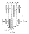
- FIGS. 8A to 8G in order to make it easier to understand, a part of the arrangement of the tip of the coil segment in the circumferential direction and the corresponding arrangement of the accommodation recess of the inner twist jig 26 in the circumferential direction are linearly developed. The positional relationship between them is schematically shown.
- the short tip portion 12d, the tall tip portion 14d, and the tip portion 16d in the drawing include a portion where the insulating coating has been peeled off and a portion where the insulating coating has not been peeled off, respectively.
- the short tip portion 12d of the normal coil segment 12 protruding from the end surface of the core 6 of the stator 2 and the tall tip portion 14d of the deformed coil segment 14 are the core 6
- the slots are arranged at the same slot pitch P1 in the circumferential direction (arrow R direction).
- the slot pitch P1 is the forming pitch of the slot 4.
- the longer slot insertion portion of the coil segment 16 is also arranged at the same slot pitch P1.
- the first accommodating recess 38a of the inner twist jig 26 is formed according to the position in the circumferential direction of the short tip portion 12d arranged in the slot 4, and the stator 2 including the core 6 is formed along the central axis. Is brought closer to the inner twist jig 26 so that the corresponding short tip portion 12d can be accommodated in each of the first accommodating recesses 38a.
- the second accommodating recess 38b is relative to the tall tip 14d to be accommodated in the second accommodating recess 38b when the first accommodating recess 38a and the short tip 12d to be accommodated therein face each other. , It is formed at a position shifted in the circumferential direction (left side in the figure).
- the second accommodating recess 38b is arranged at a position deviated from the arrangement cycle of the first accommodating recess 38a.
- FIG. 8B shows the positional relationship between the third accommodating recess 38c and the second accommodating recess 38b in the same manner as in FIG. 8A.
- the third accommodating recess 38c also has the circumferential direction of the tip 16d, which is the longer end of the coil segment 16 arranged in the slot 4, like the first accommodating recess 38a.
- the circumferential position of the inner twist jig 26 is adjusted so that the short tip portion 12d corresponding to each first accommodating recess 38a can be accommodated, the tip corresponding to each third accommodating recess 38c can be accommodated at that position. A portion 16d can be accommodated.
- a stator 2 which is a core 6 into which a coil segment is inserted is prepared and set in the twist device 18 of FIG.
- the inner twist jig 26 is driven to move its circumferential position to a position for starting the primary twist.
- the position is a position where the tall tip portion 14d and the second accommodating recess 38b of the inner twist jig 26 face each other.
- the first accommodating recess 38a comes to a position deviated from the short tip portion 12d accommodated therein.
- the virtual line L shows the position where the tall tip portion 14d was in the state of FIG. 8A.
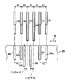
- the stator 2 is lowered as shown by the arrow Z2 by the operation of the drive mechanism 34 by the control unit 25, and as shown in FIG. 8D, the tall tip portion 14d of the deformed coil segment 14 A part is inserted into the second accommodating recess 38b.
- the amount of descent of the stator 2 not only the short tip portion 12d is not accommodated in the first accommodating recess 38a, but also the tip portion 16d of the longer slot insertion portion of the coil segment 16 which is the neutral wire is also accommodated in the third accommodating recess 38c.
- the height of the tip portion 16d in the state of FIG. 8D is shown by a virtual line in the figure.
- the setting of the lowering amount can be stored in the non-volatile memory 25a of the control unit 25.
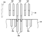
- the inner twist jig 26 is rotationally driven in the R1 direction by a predetermined amount to perform the primary twist.
- FIG. 8E shows the state after this primary twist.
- the tall tip portion 14d is deformed diagonally by the primary twist.
- the predetermined amount of rotation of the inner twist jig 26 in the primary twist is 1/2 of the formation pitch P2 of the first accommodating recess 38a. That is, it is rotated by the amount of deviation of the second accommodating recess 38b described above. Strictly speaking, this amount of rotation is preferably set by adding springback to (1/2) ⁇ P2.
- the short tip portion 12d and the tip portion 16d are not inserted into the first accommodating recess 38a and the third accommodating recess 38c, respectively, so that the positions do not change. Therefore, in relation to the above rotation amount, as shown in FIG. 8E, after the end of the primary twist, the first accommodating recess 38a and the third accommodating recess 38c face each other at the short tip portion 12d and the tip portion 16d, respectively. ..
- the short tip portion 12d is inserted into the first accommodating recess 38a and the tip portion 16d is inserted into the third accommodating recess 38c by further lowering the stator 2 as shown by the arrow Z2. be able to.
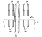
- the secondary twist is performed by rotating the inner twist jig 26 more than a predetermined amount at the time of the primary twist. Even if there is a time lag between the primary twist and the secondary twist, the transition from the primary twist to the secondary twist may be continuous.
- the secondary twist is performed in the opposite direction to the primary twist, as shown in FIG. 8G. That is, the inner twist jig 26 is rotationally driven in the direction opposite to that in the case of the primary twist (arrow R2 direction).
- the amount of rotation of the inner twist jig 26 in the secondary twist is one or more times the formation pitch P2 of the first accommodating recess 38a. It is not limited to an integral multiple of P2.
- FIG. 9 shows the configuration of the input leader line at the time when the above secondary twist is completed.
- the amount of rotation of the inner twist jig 26 in the secondary twist is set to three times the formation pitch P2 of the first accommodating recess 38a.
- the tall tip portion 14d of the deformed coil segment 14 the amount displaced by the primary twist is offset by the secondary twist in the opposite direction.
- the tall tip portion 14d is located at a position displaced 2.5 times the formation pitch P2 of the first accommodating recess 38a, that is, in the gap 21 between the joint portions 10 between the tip portions in the circumferential direction as shown in FIG. It is arranged at the corresponding position while standing perpendicular to the end face of the core 6.
- the third accommodating recess 38c is formed without providing a "deviation" with respect to the arrangement cycle of the first accommodating recess 38a as in the case of the second accommodating recess 38b. Therefore, as shown in FIG. 1, the tip portion 16d of the coil segment 16 after the secondary twist is arranged so as to be aligned with the row of the joint portions 10 in the radial direction. Further, although not essential, in this example, at the same time as the secondary twist by the inner twist jig 26, the outer twist jig 28 is also rotationally driven in the opposite direction to the inner twist jig 26 to form the second layer from the inner peripheral side. Twist the coil segment.
- the accommodating recesses 40a accommodating the tip of the coil segment in the second layer are all the same size as the first accommodating recesses 38a. This is because the tip portion arranged in the second layer is the tip portion for joining.
- the amount of rotation of the inner twist jig 26 in the primary twist (formation pitch of the first accommodating recess 38a). 1/2) and the condition of the amount of rotation of the inner twist jig 26 in the secondary twist (one or more times the formation pitch of the first accommodating recess 38a) may not be strict. That is, when the secondary twist is completed, the tip portion 14d of the deformed coil segment 14 may be set to stand up in the gap 21 at a position that does not hinder the bending process for lying down, which will be described later.
- the first accommodating recess 38a is formed in the short tip portion 12d accommodated therein.
- the first accommodating recess 38a and the first accommodating recess 38a are located so that the short tip portion 12d comes to a position substantially opposite to the first accommodating recess 38a after the primary twist. It forms two accommodating recesses 38b. Then, after performing the primary twist of only the deformed coil segment 14, the secondary twist is performed.
- the position of the tall tip portion 14d can be shifted from the position of the row of the joint portions 10 by using a single twist jig (inner twist jig 26), and the above-mentioned horizontal connection configuration can be facilitated. Can be obtained.
- the secondary twist is performed in the opposite direction to the primary twist, but even when rotated in the same direction, the short tip portion 12d in which the tall tip portion 14d forms the joint portion 10 in the primary twist. Since it advances by a predetermined amount as compared with the above, the same effect can be obtained. Since the bent portion 14d-1 may be shorter when the secondary twist is performed in the opposite direction to the primary twist, the length of the tall tip portion 14d of the deformed coil segment 14 can be shortened, which is economical from the viewpoint of material cost. Is the target. Further, in the present embodiment, the stator 2 is moved and the tip end portion of each coil segment is inserted into the corresponding accommodating recess, but the twist jig side or both the stator 2 and the twist jig may be moved.
- stator 2 it is preferable to bring the stator 2 closer to the inner twist jig 26 as the inner twist jig 26 rotates.
- at least one of the stator 2 and the twist jig 22 may be relatively moved with respect to the other in the direction along the central axis thereof. That is, contrary to the case of the present embodiment, the stator 2 may be fixed and the twist jig 22 side may be raised, and further, the stator 2 may be lowered and the twist jig 22 side may be raised at the same time.
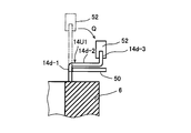
- the terminal member shown in FIG. 1 with respect to the tall tip portion 14d which becomes the input lead wires 14U1, 14U2, 14V1, 14V2, 14W1, 14W2 in a state of standing vertically as shown in FIG. 9 after the secondary twist. Bending is performed to connect to 15U, 15V, and 15W. This bending process will be described with reference to FIGS. 10A and 10B.
- the bending process for lying down is performed by the following procedure. First, as shown in FIG. 10A, a bending guide member 50 that guides the bending of the base of the input lead wire 14U1 is inserted from the radial outside of the core 6, and in that state, the tip of the input lead wire 14U1 is inserted. It is housed in the bending member 52 of the processing apparatus.
- the tall tip portion 14d serving as the input lead wire 14U1 is bent so as to lie in the gap 21 and the lead-out portion 14d. -2 is formed. After that, the tip portion thereof is further bent by the bending member 52 in the axial direction of the core 6 to form the rising portion 14d-3.
- the twisting of the coil segment of the innermost layer by the twist jig 22 has been described, but also for each of the other layers, the portion of the coil segment protruding from the end face of the core 6 by using the twist jig corresponding to each layer. Can be twisted. Since there is no coil segment serving as an input lead wire in the other layers, only the first accommodating recesses 38a need to be provided at equal intervals in the twist jig corresponding to the other layers, and the second accommodating recesses 38b And the third accommodating recess 38c is unnecessary. Also, the twist direction is opposite to that of the adjacent layer. Further, the twist may be performed in two layers by using two twist jigs.
- the first to third accommodating recesses 38a to 38c are formed in a vertical groove shape extending in the axial direction on the outer peripheral surface of the core 6, but are formed on the inner peripheral surface or the inner side of the jig body 36. May be good. Alternatively, it may be formed as a hole that is not exposed on the side surface inside the side surface of the jig body 36. Similarly, the accommodating recess 40a may be formed on the inner peripheral surface, the inner surface, the inside of the side surface, or the like of the jig main body 40.
- an example is shown in which an input lead wire is laid in a gap 21 between the joints 10 in the circumferential direction of a normal coil segment and led out from the inner peripheral side to the outer peripheral side.
- the invention is not limited to this, and may be configured to be derived from the outer peripheral side to the inner peripheral side.
- the twist jig having a diameter corresponding to the outermost layer is provided with the accommodating recesses corresponding to the first to third accommodating recesses 38a to 38c, and FIGS. 8A to 8G are provided with respect to the slot insertion portion of the outermost layer.
- a twisting process similar to that described with reference to may be applied.
- the object to be laid in the gap 21 is not limited to the input lead wire.
- the tip portion 16d of the longer slot insertion portion of the coil segment 16 is also twisted in the primary twist. You may try to twist it. In this way, the tip portion 16d (the tip portion that becomes the neutral wire) of the longer slot insertion portion of the coil segment 16 also has a gap between the joint portions 10 as in the case of the tall tip portion 14d of the deformed coil segment 14. It can be arranged at the position corresponding to 21.
- FIG. 11A shows an example of arrangement of the first to third accommodating recesses 38a to 38c when such a primary twist is performed.
- the same reference numerals are used for the parts corresponding to the configurations shown in FIGS. 8A to 8G.
- the third accommodating recess 38c is a third accommodating recess in a state where the first accommodating recess 38a and the short tip portion 12d to be accommodated thereof face each other. It is formed at a position shifted in the circumferential direction (left side in the figure) with respect to the tip portion 16d to be accommodated in 38c.
- the third accommodating recess 38c is also arranged at a position deviated from the arrangement cycle of the first accommodating recess 38a, similarly to the second accommodating recess 38b.
- FIG. 11B shows a part of the twist operation using the inner twist jig of FIG. 11A.
- each accommodating recess 38a, the second accommodating recess 38b, and the third accommodating recess 38c have different depths.
- the tip portion accommodated in each accommodating recess does not need to be in the accommodating recess until it reaches the bottom of the accommodating recess. Therefore, each accommodating recess may be formed deeper than the depth required for accommodating the corresponding tip.
- the depth of each accommodating recess may be the same as the deepest second accommodating recess 38b in FIG. In this case, all the accommodating recesses have the same shape.
- first accommodating recess 38a and the third accommodating recess 38c are formed at equal intervals at the pitch of P2, and as described with reference to FIG. 8A, the second accommodating recess 38b is positioned according to the pitch of P2. It may be formed at a position deviated by 1/2 pitch from the above.
Abstract
最内層に対応する内側ツイスト治具(26)の外周面には、周方向に間隔をおいて、通常のコイルセグメント(12)のスロット挿入部(12a)の先端部(12d)を収容する第1収容凹部(38a)と、異形のコイルセグメント(14)の長身のスロット挿入部(14b)の先端部(14d)を収容する第2収容凹部(38b)が複数形成されている。第2収容凹部(38b)にツイスト前の長身スロット挿入部(14b)の先端部(14d)を挿入した状態では、第1収容凹部(38a)は、収容すべき先端部(12d)に対して周方向にずれた位置にある。この状態で内側ツイスト治具(26)を回転させて1次ツイストを行い、その後さらに第1収容凹部(38a)に通常のコイルセグメント(12)の先端部(12d)を挿入して、1次ツイストよりも多い回転量で2次ツイストを行う。
Description
本発明は、モータや発電機等の回転電機のステータにおけるコイルセグメントのツイスト方法ならびに、コイルセグメントのツイスト処理に用いられるツイスト治具及びツイスト装置に関する。
モータや発電機等の回転電機におけるステータのコイルとして、いわゆるセグメント型コイルが知られている。このセグメント型コイルは、ステータコア(以下、コアと略す)の周方向に沿って配列された複数のスロットに、直線状に延びる一対のスロット挿入部を備えたU字状のコイルセグメントを複数、スロットの間を跨ぐように挿入してコアの径方向に複数の層を形成し、これらコイルセグメントのコア端面から突出した挿入方向の先端部を層毎に逆向きにツイスト加工してコアの径方向で隣り合う層(レイヤー)の先端部同士を溶接等により電気的に接合したものである。U字状のコイルセグメントはヘアピンとも称されている。
ツイスト加工は、捻り曲げ、折り曲げの概念を含むものとし、以下ではツイストと略す。
ツイスト加工は、捻り曲げ、折り曲げの概念を含むものとし、以下ではツイストと略す。
上記のコイルセグメントの中には、入力線や中性線などの引き出し線となるものが含まれており、これらは、先端部同士が接合される通常のコイルセグメントよりもコアの端面からの突出長さが大きい異形のコイルセグメントとなる。
従来知られているツイストの手法においては、ツイストをする場合、通常のコイルセグメントの先端部と、該通常のコイルセグメントと同じ層に位置する異形のコイルセグメントの先端部とは同一のツイスト治具に挿入され、ツイスト治具の回転により、層毎に周方向の同一向きに且つ径方向で隣り合う層のコイルセグメントとは逆向きにツイストされる。
このため、ツイスト後の異形のコイルセグメントの先端部の、コアの周方向の位置は、通常のコイルセグメントの先端部と同じ位置となる。すなわち、通常のコイルセグメントの先端部の接合部列と、異形のコイルセグメントとの先端部とは、コアの径方向に揃った位置に来る。
従来知られているツイストの手法においては、ツイストをする場合、通常のコイルセグメントの先端部と、該通常のコイルセグメントと同じ層に位置する異形のコイルセグメントの先端部とは同一のツイスト治具に挿入され、ツイスト治具の回転により、層毎に周方向の同一向きに且つ径方向で隣り合う層のコイルセグメントとは逆向きにツイストされる。
このため、ツイスト後の異形のコイルセグメントの先端部の、コアの周方向の位置は、通常のコイルセグメントの先端部と同じ位置となる。すなわち、通常のコイルセグメントの先端部の接合部列と、異形のコイルセグメントとの先端部とは、コアの径方向に揃った位置に来る。
このような従来の手法を用いると、例えば、コアの最も内周側の層(最内層)に位置する異形のコイルセグメントによる引き出し線を、径方向の外側に配置された端子部材に電気的に接続する場合には、通常のコイルセグメントの先端部の接合部列の上方を跨ぐように渡らせて接続する構成とならざるを得ない。
特許文献1に記載のコイルはU字状のものを挿入する構成ではないが、その図17(B)から明らかなように、コイルの端部をコアの径方向に曲げて小型化を図ることについて上記のような手法が採られている。
特許文献1に記載のコイルはU字状のものを挿入する構成ではないが、その図17(B)から明らかなように、コイルの端部をコアの径方向に曲げて小型化を図ることについて上記のような手法が採られている。
上記のように引き出し線が接合部列の上方を跨ぐ接続構成では、異形のコイルセグメントの引き出し部分の長さを大きくとる必要があり、それだけ銅やアルミニウム等で形成されるコイルセグメントの材料費の増加に繋がる。
また、この種のステータではコア端面からのコイルの突出量は少なければ少ない程モータ等の小型化に寄与し、ミリ単位で影響が出るが、上記のような接続構成は小型化を阻害する。
また、引き出し線の立ち上がり高さが大きいと、引き出し線と端子部材との間の接続部の剛性も低下するため、引き出し部の固有振動数が低下する。このため、例えば車両エンジンの回転に伴う振動と共振して結線部に断線応力をもたらす懸念もある。
また、この種のステータではコア端面からのコイルの突出量は少なければ少ない程モータ等の小型化に寄与し、ミリ単位で影響が出るが、上記のような接続構成は小型化を阻害する。
また、引き出し線の立ち上がり高さが大きいと、引き出し線と端子部材との間の接続部の剛性も低下するため、引き出し部の固有振動数が低下する。このため、例えば車両エンジンの回転に伴う振動と共振して結線部に断線応力をもたらす懸念もある。
本発明は、このような現状に鑑みてなされたもので、コイルセグメントを用いた回転電機のステータにおいて、コイルセグメントと端子部材との間の接続部の低コスト化と剛性の向上を図るとともに、回転電機の小型化に寄与することを目的とする。
上記目的を達成するための本発明によるコイルセグメントのツイスト方法においては、まず、回転電機のステータを構成すべきコアの周方向に配列された複数のスロットに、複数のコイルセグメントが挿入されており、前記コアの端面から前記挿入の挿入方向に向けて突出する前記各コイルセグメントの先端部が前記コアの径方向に複数の層を形成し、前記複数の層のうちの一つの層に、他のコイルセグメントの先端部と接合されるべき先端部である短身先端部と、該短身先端部よりも長く前記コアの端面から突出する長身先端部とが配置されている被加工物を用意する。
そして前記短身先端部を収容するための第1収容凹部と前記長身先端部を収容するための第2収容凹部とを備えたツイスト治具の前記第2収容凹部に前記長身先端部の少なくとも一部を挿入し、前記第1収容凹部に前記短身先端部を挿入していない状態で、前記ツイスト治具を所定量回転させて1次ツイストを行った後、前記第2収容凹部に前記長身先端部を挿入したまま、さらに前記第1収容凹部に前記短身先端部の少なくとも一部を挿入した状態で、前記ツイスト治具を前記所定量よりも多く回転させる2次ツイストを行う。
本発明によるコイルセグメントのツイスト方法では、上記1次ツイストと2次ツイストにより、周方向で見て、隣り合う前記短身先端部の間の位置に前記長身先端部を配置するように、前記複数のコイルセグメントの先端部をツイストする。
このようなコイルセグメントのツイスト方法において、前記1次ツイストを行う前は、前記ツイスト治具の前記各第2収容凹部に前記長身先端部の前記少なくとも一部を挿入した状態で、前記各第1収容凹部は、該第1収容凹部に収容すべき前記短身先端部と前記周方向にずれた位置にあり、前記1次ツイストを行った後は、前記第1収容凹部が、該第1収容凹部に収容すべき前記短身先端部と略対向する位置に来るとよい。
さらに、前記長身先端部が配置されている層が、前記径方向の最内層又は最外層であるとよい。
さらに、前記1次ツイストでの前記ツイスト治具の回転量が、前記スロットの形成ピッチの略1/2であり、前記2次ツイストでの前記ツイスト治具の回転量が、前記スロットの形成ピッチの1倍以上であるとよい。
さらに、前記2次ツイストを前記1次ツイストと逆向きに行うとよい。
さらに、前記1次ツイストでの前記ツイスト治具の回転量が、前記スロットの形成ピッチの略1/2であり、前記2次ツイストでの前記ツイスト治具の回転量が、前記スロットの形成ピッチの1倍以上であるとよい。
さらに、前記2次ツイストを前記1次ツイストと逆向きに行うとよい。
また、この発明は、上記のように方法として実施する他、上記のツイスト方法の実施に適したツイスト治具や、ツイスト装置として実施することができる。当該ツイスト装置の動作方法、ツイスト装置の制御に用いるプログラムやそのプログラムを格納した記録媒体として実施することも妨げられない。
上記の構成によれば、コイルセグメントを用いた回転電機のステータにおいて、コイルセグメントと端子部材との間の接続部の低コスト化と剛性の向上を図れるとともに、回転電機の小型化に寄与できる。
以下、本発明の一実施形態について図を参照して説明する。
まず、図1を参照して、本発明のコイルセグメントのツイスト方法を用いて作成することができる回転電機のステータの一例の概略構成を説明する。
図1は、そのステータの斜視図である。
図1に示すステータ2は、周方向に配列された複数のスロット4を有する円筒状のコア6と、スロット4にU字状のコイルセグメント(セグメント導体)をスロット4の間を跨ぐように複数挿入してそれらのコイルセグメントを接続することにより構成された3相(U相、V相、W相)のコイル8とを備えている。符号5はコア6とコイルセグメントとの間を絶縁するための絶縁シートを示している。なお、以降の説明において、「U」を含む符号はU相のコイルに関連した構成を示す。「V」、「W」についても同様である。
図1は、そのステータの斜視図である。
図1に示すステータ2は、周方向に配列された複数のスロット4を有する円筒状のコア6と、スロット4にU字状のコイルセグメント(セグメント導体)をスロット4の間を跨ぐように複数挿入してそれらのコイルセグメントを接続することにより構成された3相(U相、V相、W相)のコイル8とを備えている。符号5はコア6とコイルセグメントとの間を絶縁するための絶縁シートを示している。なお、以降の説明において、「U」を含む符号はU相のコイルに関連した構成を示す。「V」、「W」についても同様である。
各コイルセグメントはコア6の図中軸方向下側からスロット4に挿入され、図中コア6の軸方向上側(入力側又は給電側)の端面から突出した部分は、後述するツイスト治具によりコア6の周方向に折り曲げられる。折り曲げ(ツイスト)はコア6の径方向で隣り合う層毎に逆向きに行われ、ツイスト後に径方向で隣り合う層間で対向するコイルセグメントの先端部同士が電気的に接合される。
図1では接合前の状態を示しているが、以下の説明では、先端部同士が対向した構成(厳密にはコイルセグメントの先端の絶縁被膜を除去した部分同士が対向する構成)を接合部10と称する。
図1では接合前の状態を示しているが、以下の説明では、先端部同士が対向した構成(厳密にはコイルセグメントの先端の絶縁被膜を除去した部分同士が対向する構成)を接合部10と称する。
なお、ステータ2において、各スロット4には6本のコイルセグメントのスロット挿入部(後述)が挿入される。コイルセグメントの厚さは全て共通であるので、1つのスロット4に挿入される6つのスロット挿入部の径方向の配置は全てのスロットにおいて共通である。このため、1つのスロットに挿入される6つのスロット挿入部は、最外周側から最内周側まで積み重なった6層を形成すると捉えることができ、本明細書で「層」と言った場合には、特に断らない限り、このスロット挿入部の層を意味するものとする。
コア6は、打ち抜き加工又はエッチング加工により成形された薄肉の円環状の電磁鋼鈑を円筒軸方向に積層して一体化した構成を有している。コア6の内周側には中心に向けて突出する複数のティース(磁極歯)7が周方向に所定間隔で放射状に形成されている。各ティース7の先端側の面によりコア6の内周面が概ね形成されるが、各ティース7の先端側の面は相互に離れている。図1の中央付近の符号を見易くするため、図の一部を白く塗りつぶしているが、塗りつぶし部分においても、各ティース7は相互に離れている。また、隣り合うティース7間にスロット4が形成されている。
本実施形態のステータ2に挿入される不図示のロータの極数(磁極数)は8であり、極数8に対する3相のコイル8の1相あたりのスロット数は2である。従って、コア6には総数48のスロット4が配置されている。
本実施形態のステータ2に挿入される不図示のロータの極数(磁極数)は8であり、極数8に対する3相のコイル8の1相あたりのスロット数は2である。従って、コア6には総数48のスロット4が配置されている。
ここで、図2Aにコイルセグメントの一例を示す。
各コイルセグメントは、表面が絶縁被膜で覆われた平角線を曲げ加工によりU字状に変形して形成されている。具体的に説明すると、図2Aに示すように、コイルセグメント12はそれぞれ直線状に延びる一対のスロット挿入部12a,12bと、これらを連結する連結部12cとを備え、一方のスロット挿入部12aと他方のスロット挿入部12bをそれぞれ異なる層に配置できるように連結部12cは段差形状を有している。
各コイルセグメントは、表面が絶縁被膜で覆われた平角線を曲げ加工によりU字状に変形して形成されている。具体的に説明すると、図2Aに示すように、コイルセグメント12はそれぞれ直線状に延びる一対のスロット挿入部12a,12bと、これらを連結する連結部12cとを備え、一方のスロット挿入部12aと他方のスロット挿入部12bをそれぞれ異なる層に配置できるように連結部12cは段差形状を有している。
符号12dは、コイルセグメント12をコア6に挿入した時にコア6の端面から突出する範囲を示している。
また、各スロット挿入部12a,12bの挿入方向の先端側の所定長さの部分(符号12dで示す範囲よりも狭い範囲)では、絶縁被膜が除去され、他のコイルセグメントのスロット挿入部や接続端子等と電気的に接続することが可能である。
また、各スロット挿入部12a,12bの挿入方向の先端側の所定長さの部分(符号12dで示す範囲よりも狭い範囲)では、絶縁被膜が除去され、他のコイルセグメントのスロット挿入部や接続端子等と電気的に接続することが可能である。
本実施形態のコイルセグメントには、図1に示すように接合部10で他のコイルセグメントと連結される先端部を有する、図2Aに示したように同じ長さのスロット挿入部12a,12bを備える通常のコイルセグメント12の他、コイルセグメント12よりもコア6の端面からの突出長さが長いスロット挿入部を含む異形のコイルセグメント14と、同様にコイルセグメント12よりもコア6の端面からの突出長さがコイルセグメント12よりも長く、中性線となる先端部を有するコイルセグメント16とが含まれている。
図2Bに異形のコイルセグメント14の一例を示す。
この異形のコイルセグメント14も、直線状に延びる一対のスロット挿入部14a,14bと、これらを連結する連結部14cとからなり、連結部14cは層替えのための段差形状(クランク形状)を有している点はコイルセグメント12と共通である。
この異形のコイルセグメント14も、直線状に延びる一対のスロット挿入部14a,14bと、これらを連結する連結部14cとからなり、連結部14cは層替えのための段差形状(クランク形状)を有している点はコイルセグメント12と共通である。
しかし、異形のコイルセグメント14の一方のスロット挿入部14bは、通常のコイルセグメント12のスロット挿入部12a,12bと長さが同等である他方のスロット挿入部14aよりも長い。スロット挿入部14bの先端部は、スロット挿入部12a,12b,14aの先端部よりも長く、コア6の端面から突出し、その先端部は入力用引き出し線となる。符号14dは、コイルセグメント14をコア6に挿入した時にスロット挿入部14bがコア6の端面から突出する範囲を示している。スロット挿入部14a側では、図2Aの12dと同じ長さの部分が突出する。
以下、符号14dで示す部分を長身先端部と、符号12dで示す部分を短身先端部と呼ぶ。
以下、符号14dで示す部分を長身先端部と、符号12dで示す部分を短身先端部と呼ぶ。
また、図2Cに中性線となる先端部を有するコイルセグメント16の一例を示す。
このコイルセグメント16も、一方のスロット挿入部16bの長さが他方のスロット挿入部16aの長さよりも若干長い。
また厳密には、通常のコイルセグメント12も、コア6の径方向の位置に応じてスロット4間の周長が異なることに対応して、各スロット挿入部のコア6の端面からの突出長さは、そのスロット挿入部がどの層を形成するかによって若干異なる。
このコイルセグメント16も、一方のスロット挿入部16bの長さが他方のスロット挿入部16aの長さよりも若干長い。
また厳密には、通常のコイルセグメント12も、コア6の径方向の位置に応じてスロット4間の周長が異なることに対応して、各スロット挿入部のコア6の端面からの突出長さは、そのスロット挿入部がどの層を形成するかによって若干異なる。
しかし、コイルセグメント12,16におけるスロット挿入部間の長さの差は、図2Bのmに比べて小さいため、コイルセグメント14のスロット挿入部14b(の先端部14d)のみを、他よりも長いスロット挿入部14bとして、後述する1次ツイストの対象とする。
図1の説明に戻ると、各スロット4には、前述のようにコア6の径方向に1列に並ぶように6本のスロット挿入部が挿入されている。そして、各相のコイルは、接合部10において対向するスロット挿入部を電気的に接続することにより複数のコイルセグメントを直列に接続して、それぞれコア6を略6周する、配置位置が周方向にずれた2本のコイルを形成し、さらにそれら2本のコイルを並列に接続した構成を有している。各コイルは、最内周の層(最内層)から最外周の層(最外層)に向けて引き回され、また最内層に戻る構成を有し、両端ともに最内層に位置する。
図1に示すように、コア6の最内層には、異形のコイルセグメント14の長身先端部14dを曲げて形成した入力用引き出し線14U1,14U2,14V1,14V2,14W1,14W2が配置されている。これらの引き出し線の先端部はそれぞれ、例えばインバータの交流出力部に接続される端子部材15U,15V,15Wに電気的に接続されている。図1で符号を付した入力用引き出し線14U1~14W2は、それぞれ各コイルの一端部に位置し、例えば端子部材15Uは、U相の2本のコイルを並列接続する役割も果たす。V相及びW相についても同様である。
また、最内層には、コイルセグメント16の長い方のスロット挿入部の先端部により形成される中性線16U1,16U2,16V1,16V2,16W1,16W2も配置されており、これらは中性点としての不図示の長板状のコモン導体に電気的に接続されている。中性線16U1~16W2は、各コイルの他端部に位置する。
ここで、図3に図1の要部を拡大して示す。
図3に示すように、入力用引き出し線14U1,14U2,14V1,14V2は、コア6の周方向におけるコイルセグメント12同士の接合部10の間(径方向に並ぶ接合部10の列間の周方向の隙間21)に、横たわるように配置されている。図3に表れない(図1には表れる)入力用引き出し線14W1,14W2も同様である。
即ち、径方向の一端側である最内層に位置し、接合部10で接合される先端部を有する通常のコイルセグメント12よりもコア6の端面からのスロット挿入部の突出長さが大きい異形のコイルセグメント14の先端部が、接合部10間の隙間21内に横たわるように配置されて、径方向の他端側(最外周側)に導出されている。
図3に示すように、入力用引き出し線14U1,14U2,14V1,14V2は、コア6の周方向におけるコイルセグメント12同士の接合部10の間(径方向に並ぶ接合部10の列間の周方向の隙間21)に、横たわるように配置されている。図3に表れない(図1には表れる)入力用引き出し線14W1,14W2も同様である。
即ち、径方向の一端側である最内層に位置し、接合部10で接合される先端部を有する通常のコイルセグメント12よりもコア6の端面からのスロット挿入部の突出長さが大きい異形のコイルセグメント14の先端部が、接合部10間の隙間21内に横たわるように配置されて、径方向の他端側(最外周側)に導出されている。
さらに具体的に説明すると、入力用引き出し線14U1,14U2,14V1,14V2は、異形のコイルセグメント14の長身先端部14dを、同じ層の通常のコイルセグメント12の短身先端部12dと共に周方向の同じ向きに折り曲げて(ツイストして)形成された折り曲げ部14d-1と、接合部10の列間の隙間21を内周側から外周側に向って延びる導出部14d-2と、最外層よりも外側に突出した位置で導出部14d-2の先端からコア6の軸方向に立ち上がる立ち上がり部14d-3とを有する。立ち上がり部14d-3は端子部材15U,15Vに接続されている。
導出部14d-2は、隙間21に対応する位置で径方向に折り曲げられた部分である。
図1に示す入力用引き出し線14W1,14W2も同様な構成を有する。
導出部14d-2は、隙間21に対応する位置で径方向に折り曲げられた部分である。
図1に示す入力用引き出し線14W1,14W2も同様な構成を有する。
図4に、図1のIV-IV線に沿う概要断面図を示す。
上記のような入力用引き出し線及び端子部材による端子接続構成を採ることにより、図4に示すように、入力用引き出し線14U1を、コア端面からの高さが低い短い距離で端子部材15Uに接続することができる。他の入力用引き出し線についても同様である。
これにより、入力用引き出し線を最内層の位置に立ち上げ、端子部材が接合部10の列の上方を跨いで入力用引き出し線と接続する従来の構成に比べて、コイルセグメントの材料コストの低減を図ることができる。また、入力用引き出し線の導出部14d-2のコア6の軸方向における高さを低くできるので、ステータ2の小型化に大きく寄与する。
上記のような入力用引き出し線及び端子部材による端子接続構成を採ることにより、図4に示すように、入力用引き出し線14U1を、コア端面からの高さが低い短い距離で端子部材15Uに接続することができる。他の入力用引き出し線についても同様である。
これにより、入力用引き出し線を最内層の位置に立ち上げ、端子部材が接合部10の列の上方を跨いで入力用引き出し線と接続する従来の構成に比べて、コイルセグメントの材料コストの低減を図ることができる。また、入力用引き出し線の導出部14d-2のコア6の軸方向における高さを低くできるので、ステータ2の小型化に大きく寄与する。
図4の構成では立ち上がり部14d-3の立ち上がりの長さを比較的長くしているが、ここで説明した端子接続構成では、立ち上がり長さがより短くても、また、立ち上がり部14d-3自体を設けなくても、コイルと端子部材との接続が可能である。この構成によれば、コイルセグメントの材料コスト低減及びステータ2の小型化の効果を一層大きくすることができる。
また、入力用引き出し線の導出部14d-2のコア6の軸方向における高さを低くできるので、入力用引き出し線と端子部材との間の接続部の剛性を高めることができる。このことにより、入力用引き出し線の固有振動数を高めることができる。すなわち、接続部の剛性が低いと入力用引き出し線の固有振動数が低下するが、この低下を抑制することができる。このように固有振動数を高めることにより、例えば接続部が車両エンジンの回転に伴う振動と共振して結線部に断線応力をもたらすリスクを低減できる。
次に、図5~図8Gを参照して、上記の効果を有する端子接続構成を実現できるコイルセグメントのツイスト方法、該ツイスト方法に用いられるツイスト治具及び該ツイスト方法を実施するためのツイスト装置の実施形態について説明する。
図5は、本発明の一実施形態であるツイスト装置の概要構成図である。
図5に示すように、ツイスト装置18は、コア6の各スロット4に適当なコイルセグメントが挿入された、ツイスト前の状態のステータ2を、コイルセグメントの突出した先端部が下向きとなるように保持するワーク保持機構20と、ツイスト治具22と、該ツイスト治具22を回転駆動するための回転駆動機構24と、該回転駆動機構24を制御してツイストプログラムを実行する制御部25等を備えている。
図5は、本発明の一実施形態であるツイスト装置の概要構成図である。
図5に示すように、ツイスト装置18は、コア6の各スロット4に適当なコイルセグメントが挿入された、ツイスト前の状態のステータ2を、コイルセグメントの突出した先端部が下向きとなるように保持するワーク保持機構20と、ツイスト治具22と、該ツイスト治具22を回転駆動するための回転駆動機構24と、該回転駆動機構24を制御してツイストプログラムを実行する制御部25等を備えている。
ツイスト治具22は、図1に示したコア6の複数のスロット4に挿入されてコア6の端面から突出した、最内層及びその隣の層(内周側から2番目の層)にあるコイルセグメント12,14,16のスロット挿入部の挿入方向の先端部を、コア6の周方向に折り曲げるための工具である。
ツイスト治具22は、最内層に配置されたスロット挿入部の先端部をツイストする内側ツイスト治具26と、内周側から2番目の層に配置されたスロット挿入部の先端部をツイストする外側ツイスト治具28とを有している。内側ツイスト治具26は異形のコイルセグメント14のスロット挿入部14bを構成する長身先端部14dが配置される径方向の最内層に対応した径を有し、外側ツイスト治具28は内周側から2番目の層に対応した径を有している。
ツイスト治具22は、最内層に配置されたスロット挿入部の先端部をツイストする内側ツイスト治具26と、内周側から2番目の層に配置されたスロット挿入部の先端部をツイストする外側ツイスト治具28とを有している。内側ツイスト治具26は異形のコイルセグメント14のスロット挿入部14bを構成する長身先端部14dが配置される径方向の最内層に対応した径を有し、外側ツイスト治具28は内周側から2番目の層に対応した径を有している。
回転駆動機構24は、内側ツイスト治具26及び外側ツイスト治具28をそれぞれ回転駆動する回転駆動機構を備える。当該回転駆動機構は、モータ30の動力により内側ツイスト治具26を駆動すると共に、モータ32の動力により外側ツイスト治具28を駆動する。モータ30とモータ32はモータドライバを介して制御部25に接続されている。制御部25の不揮発メモリ25aには内側ツイスト治具26と外側ツイスト治具28の回転量と回転方向等のデータが記憶されており、制御部25はこのデータに基づいて回転駆動機構24を制御する。
ワーク保持機構20は駆動機構34により上下方向(矢印Z方向)に移動可能となっており、ツイスト時にはステータ2の下降移動とツイスト治具22の回転動作が制御部25の制御により同時になされる。
ワーク保持機構20は駆動機構34により上下方向(矢印Z方向)に移動可能となっており、ツイスト時にはステータ2の下降移動とツイスト治具22の回転動作が制御部25の制御により同時になされる。
図6は、図5のツイスト装置におけるツイスト治具の分解斜視図である。
図6に示すように、内側ツイスト治具26は、回転駆動機構24に接続される円筒状の治具本体36と、該治具本体36の軸方向上端部の外周面に形成された、第1収容凹部38a、第2収容凹部38b及び第3収容凹部38cを有している。第1収容凹部38a、第2収容凹部38b及び第3収容凹部38cは、周方向に間隔をおいて複数形成されている。
図6に示すように、内側ツイスト治具26は、回転駆動機構24に接続される円筒状の治具本体36と、該治具本体36の軸方向上端部の外周面に形成された、第1収容凹部38a、第2収容凹部38b及び第3収容凹部38cを有している。第1収容凹部38a、第2収容凹部38b及び第3収容凹部38cは、周方向に間隔をおいて複数形成されている。
図7は、図6のVII-VII線に沿う内側ツイスト治具26の概要断面図である。
図7に示すように、治具本体36の底面36aには回転駆動機構24の駆動軸が挿入される挿入孔36bが形成され、さらに複数(ここでは4つ)のネジ孔36cが周方向に等間隔で形成されている。治具本体36はこれらのネジ孔36cを介して回転駆動機構24にボルトで締結される。
治具本体36の上端側には、各コイルセグメントのスロット挿入部の先端部を各収容凹部に案内するための段差状の環状ガイド面36dが形成されている。
図7に示すように、治具本体36の底面36aには回転駆動機構24の駆動軸が挿入される挿入孔36bが形成され、さらに複数(ここでは4つ)のネジ孔36cが周方向に等間隔で形成されている。治具本体36はこれらのネジ孔36cを介して回転駆動機構24にボルトで締結される。
治具本体36の上端側には、各コイルセグメントのスロット挿入部の先端部を各収容凹部に案内するための段差状の環状ガイド面36dが形成されている。
第1収容凹部38aは、コイルセグメント12,14,16が備えるスロット挿入部のうち、接合部10を構成し、相互に電気的に接合されるべき一対のスロット挿入部の先端部(短身先端部12d)を収容する。
第2収容凹部38bは、異形のコイルセグメント14の、入力用引き出し線14U1,14U2,14V1,14V2,14W1,14W2となるスロット挿入部14bの先端部(長身先端部14d)を収容する。
第3収容凹部38cは、軸方向の高さが第2収容凹部38bよりも小さくて第1収容凹部38aよりも大きく、中性線となるコイルセグメント16の長い方のスロット挿入部16bの先端部(図2C参照。以下、先端部16dと呼ぶ)を収容する。
第2収容凹部38bは、異形のコイルセグメント14の、入力用引き出し線14U1,14U2,14V1,14V2,14W1,14W2となるスロット挿入部14bの先端部(長身先端部14d)を収容する。
第3収容凹部38cは、軸方向の高さが第2収容凹部38bよりも小さくて第1収容凹部38aよりも大きく、中性線となるコイルセグメント16の長い方のスロット挿入部16bの先端部(図2C参照。以下、先端部16dと呼ぶ)を収容する。
なお、各先端部のうち第1収容凹部38aに収容される範囲は、各コイルセグメント12,14,16のスロット挿入部(コイルセグメント14にあってはスロット挿入部14a)の先端から、概ね図1においてコア6の軸方向に立ち上がっている部分までの範囲である。これは、例えば短身先端部12dとして示した範囲の一部分である。
長身先端部14dのうち第2収容凹部38bに収容される範囲は、各コイルセグメント14のスロット挿入部14bの先端から、概ね図3における導出部14d-2及び立ち上がり部14d-3を構成する部分までの範囲である。これは、長身先端部14dとして示した範囲の一部分である。
先端部16dのうち第3収容凹部38cに収容される範囲もこれらに準じる。
長身先端部14dのうち第2収容凹部38bに収容される範囲は、各コイルセグメント14のスロット挿入部14bの先端から、概ね図3における導出部14d-2及び立ち上がり部14d-3を構成する部分までの範囲である。これは、長身先端部14dとして示した範囲の一部分である。
先端部16dのうち第3収容凹部38cに収容される範囲もこれらに準じる。
図6に示すように、外側ツイスト治具28は、円筒状の治具本体40と、該治具本体40の下面に治具本体40と一体に形成されたフランジ部42とを有している。治具本体40の軸方向上端部の内周面には、内周側から2番目の層に配置されたスロット挿入部の先端部を収容する収容凹部40aが周方向に間隔をおいて複数形成されている。各収容凹部40aの高さは、内側ツイスト治具26の第1収容凹部38aと同等である。
外側ツイスト治具28は、フランジ部42とウォームギヤ等の歯車構成とを介して、回転駆動機構24に接続されている。
内側ツイスト治具26と外側ツイスト治具28はそれぞれ、治具本体の側面部により、他方の治具の収納凹部に挿入されたスロット挿入部の先端部が外れて脱落するのを互いに防止し合う。
内側ツイスト治具26と外側ツイスト治具28はそれぞれ、治具本体の側面部により、他方の治具の収納凹部に挿入されたスロット挿入部の先端部が外れて脱落するのを互いに防止し合う。
次に、図8A乃至図8Gを参照して、1つのツイスト治具である内側ツイスト治具26により、接合部10の列の間の隙間21に異形のコイルセグメント14の長身先端部14dを位置付けるための動作及びそのための構成について説明する。ここで説明する動作は、この発明のコイルセグメントのツイスト方法の実施形態である。
なお、図8A乃至図8Gでは、分り易くするために、コイルセグメントの先端部の周方向の配置とこれに対応する内側ツイスト治具26の収容凹部の周方向の配置の一部分を直線的に展開してこれらの位置関係を模式的に示している。また、図中の短身先端部12d、長身先端部14d及び先端部16dは、それぞれ絶縁被膜が剥離された部分と剥離されていない部分とを含んでいる。
なお、図8A乃至図8Gでは、分り易くするために、コイルセグメントの先端部の周方向の配置とこれに対応する内側ツイスト治具26の収容凹部の周方向の配置の一部分を直線的に展開してこれらの位置関係を模式的に示している。また、図中の短身先端部12d、長身先端部14d及び先端部16dは、それぞれ絶縁被膜が剥離された部分と剥離されていない部分とを含んでいる。
図8Aに示すように、ツイスト前の状態では、ステータ2のコア6の端面から突出した通常のコイルセグメント12の短身先端部12dと、異形のコイルセグメント14の長身先端部14dは、コア6の周方向(矢印R方向)に同じスロットピッチP1で配置されている。スロットピッチP1は、スロット4の形成ピッチである。
図8Bに示すように、コイルセグメント16の長い方のスロット挿入部も同じスロットピッチP1で配置されている。
図8Bに示すように、コイルセグメント16の長い方のスロット挿入部も同じスロットピッチP1で配置されている。
これに対し、内側ツイスト治具26の第1収容凹部38aは、スロット4に配置された短身先端部12dの周方向における位置に合わせて形成し、中心軸に沿ってコア6を含むステータ2を内側ツイスト治具26に近づけることにより、各第1収容凹部38aに、対応する短身先端部12dを収容できるようにしている。
一方、第2収容凹部38bは、第1収容凹部38aと、そこに収容されるべき短身先端部12dとが対向した状態では、第2収容凹部38bに収容されるべき長身先端部14dに対し、周方向(図中左側)にずれる位置に形成している。すなわち、第2収容凹部38bは、第1収容凹部38aの配置周期からずれた位置に配置されている。
第2収容凹部38bのずれ量は、本実施形態では、第1収容凹部38aの形成ピッチP2(=スロットピッチP1)の1/2である。
一方、第2収容凹部38bは、第1収容凹部38aと、そこに収容されるべき短身先端部12dとが対向した状態では、第2収容凹部38bに収容されるべき長身先端部14dに対し、周方向(図中左側)にずれる位置に形成している。すなわち、第2収容凹部38bは、第1収容凹部38aの配置周期からずれた位置に配置されている。
第2収容凹部38bのずれ量は、本実施形態では、第1収容凹部38aの形成ピッチP2(=スロットピッチP1)の1/2である。
図8Bには、第3収容凹部38cと第2収容凹部38bとの位置関係を図8Aと同様に示している。
図8Aと図8Bとの対比からわかるように、第3収容凹部38cも第1収容凹部38a同様に、スロット4に配置されたコイルセグメント16の長い方の先端部である先端部16dの周方向における位置に合わせて形成されており、中心線に沿ってコア6を含むステータ2を内側ツイスト治具26に近づけることにより、各第3収容凹部38cに、対応する先端部16dを収容することができる。なお、内側ツイスト治具26の周方向位置を、各第1収容凹部38aに対応する短身先端部12dを収容できるように調整すれば、その位置で各第3収容凹部38cにも対応する先端部16dを収容することができる。
図8Aと図8Bとの対比からわかるように、第3収容凹部38cも第1収容凹部38a同様に、スロット4に配置されたコイルセグメント16の長い方の先端部である先端部16dの周方向における位置に合わせて形成されており、中心線に沿ってコア6を含むステータ2を内側ツイスト治具26に近づけることにより、各第3収容凹部38cに、対応する先端部16dを収容することができる。なお、内側ツイスト治具26の周方向位置を、各第1収容凹部38aに対応する短身先端部12dを収容できるように調整すれば、その位置で各第3収容凹部38cにも対応する先端部16dを収容することができる。
この実施形態のツイスト方法ではまず、被加工物として、コイルセグメントが挿入されたコア6であるステータ2を用意して図5のツイスト装置18にセットする。その後、内側ツイスト治具26を駆動して、その周方向位置を、1次ツイストを開始するための位置に移動させる。
その位置は、図8Cに示すように、長身先端部14dと、内側ツイスト治具26の第2収容凹部38bとが向かい合う位置である。
図8Aとの対比からわかるように、この状態では、第1収容凹部38aは、そこに収容される短身先端部12dに対してずれた位置に来ることになる。仮想線Lは、図8Aの状態で長身先端部14dがあった位置を示している。
その位置は、図8Cに示すように、長身先端部14dと、内側ツイスト治具26の第2収容凹部38bとが向かい合う位置である。
図8Aとの対比からわかるように、この状態では、第1収容凹部38aは、そこに収容される短身先端部12dに対してずれた位置に来ることになる。仮想線Lは、図8Aの状態で長身先端部14dがあった位置を示している。
次に、図8Cに示す状態から、制御部25による駆動機構34の動作によって矢印Z2で示すようにステータ2を下降させ、図8Dに示すように、異形のコイルセグメント14の長身先端部14dの一部を第2収容凹部38bに挿入する。ステータ2の下降量は、短身先端部12dが第1収容凹部38aに収容されないことはもちろん、中性線となるコイルセグメント16の長い方のスロット挿入部の先端部16dも第3収容凹部38cに収容されない程度に設定する。図8Dの状態における先端部16dの高さを、図中に仮想線で示している。下降量の設定は、制御部25の不揮発メモリ25aに記憶させておくことができる。
次に、図8Dのように第2収容凹部38bに長身先端部14dの一部を挿入した状態で、内側ツイスト治具26をR1方向に所定量回転駆動して、1次ツイストを行う。
図8Eがこの1次ツイスト後の状態を示す。1次ツイストによって、長身先端部14dは斜めに変形する。
本実施形態における、1次ツイストでの内側ツイスト治具26の所定の回転量は、第1収容凹部38aの形成ピッチP2の1/2である。すなわち、上述した第2収容凹部38bのずれ量分だけ回転させる。厳密には、この回転量は、(1/2)×P2にスプリングバックを加味して設定することが好ましい。
図8Eがこの1次ツイスト後の状態を示す。1次ツイストによって、長身先端部14dは斜めに変形する。
本実施形態における、1次ツイストでの内側ツイスト治具26の所定の回転量は、第1収容凹部38aの形成ピッチP2の1/2である。すなわち、上述した第2収容凹部38bのずれ量分だけ回転させる。厳密には、この回転量は、(1/2)×P2にスプリングバックを加味して設定することが好ましい。
1次ツイストの時点では、短身先端部12dと先端部16dは、それぞれ第1収容凹部38a、第3収容凹部38cに挿入されていないため、位置の変動はない。このため上記回転量との関係から、図8Eに示す通り、1次ツイストの終了後には、短身先端部12dと先端部16dに、それぞれ第1収容凹部38aと第3収容凹部38cが対向する。
従ってこの状態では、矢印Z2で示すようにステータ2をさらに下降させることにより、第1収容凹部38aに短身先端部12dを、第3収容凹部38cに先端部16dを、それぞれ挿入して収容することができる。
この状態で、内側ツイスト治具26を1次ツイスト時の所定量よりも多く回転させる2次ツイストを行う。1次ツイストと2次ツイストとの間にタイムラグがあっても、1次ツイストから2次ツイストへ連続的に移行してもよい。
この状態で、内側ツイスト治具26を1次ツイスト時の所定量よりも多く回転させる2次ツイストを行う。1次ツイストと2次ツイストとの間にタイムラグがあっても、1次ツイストから2次ツイストへ連続的に移行してもよい。
上記のようにステータ2を下降させると、1次ツイストされた長身先端部14dは、斜めに変形した状態で第2収容凹部38bにさらに深く挿入されることになる。内側ツイスト治具26の各収容凹部(少なくとも第2収容凹部38b)の入口に、R形状に加工された領域を設け、当該領域に磨き加工をしておくことにより、この挿入に際してコイルセグメント14の表面の絶縁被膜と第2収容凹部38bの入口とが接触しても、絶縁被膜に傷がつかないようにすることができる。
2次ツイストは、図8Gに示すように、1次ツイストとは逆向きに行われる。即ち、内側ツイスト治具26が1次ツイストの際とは逆向き(矢印R2方向)に回転駆動される。
2次ツイストでの内側ツイスト治具26の回転量は、第1収容凹部38aの形成ピッチP2の1倍以上である。P2の整数倍には限られない。
2次ツイストでの内側ツイスト治具26の回転量は、第1収容凹部38aの形成ピッチP2の1倍以上である。P2の整数倍には限られない。
図9に、上記の2次ツイストが終わった時点での入力用引き出し線の構成を示す。
本実施形態では、2次ツイストでの内側ツイスト治具26の回転量を第1収容凹部38aの形成ピッチP2の3倍としている。これにより、通常のコイルセグメント12の短身先端部12dは第1収容凹部38aの形成ピッチP2の3倍(=3スロットピッチ)変位する。一方、異形のコイルセグメント14の長身先端部14dは、1次ツイストで変位した分が逆向きの2次ツイストで相殺される。このため、長身先端部14dは、第1収容凹部38aの形成ピッチP2の2.5倍変位した位置、すなわち、図9に示すように周方向における先端部同士の接合部10間の隙間21に対応した位置に、コア6の端面に対して垂直に立った状態で配置される。
本実施形態では、2次ツイストでの内側ツイスト治具26の回転量を第1収容凹部38aの形成ピッチP2の3倍としている。これにより、通常のコイルセグメント12の短身先端部12dは第1収容凹部38aの形成ピッチP2の3倍(=3スロットピッチ)変位する。一方、異形のコイルセグメント14の長身先端部14dは、1次ツイストで変位した分が逆向きの2次ツイストで相殺される。このため、長身先端部14dは、第1収容凹部38aの形成ピッチP2の2.5倍変位した位置、すなわち、図9に示すように周方向における先端部同士の接合部10間の隙間21に対応した位置に、コア6の端面に対して垂直に立った状態で配置される。
第3収容凹部38cは、第2収容凹部38bの場合のような、第1収容凹部38aの配置周期に対する「ずれ」を設けずに形成されている。このため、2次ツイスト後のコイルセグメント16の先端部16dは、図1に示すように、接合部10の列と径方向に並ぶように配置される。
また、必須ではないがこの例では、内側ツイスト治具26による2次ツイストと同時に、外側ツイスト治具28も内側ツイスト治具26と逆向きに回転駆動して内周側から2番目の層のコイルセグメントのツイストを行う。2番目の層におけるコイルセグメントの先端部を収容する収容凹部40aは全て第1収容凹部38aと同じ大きさである。2番目の層に配置される先端部は、接合用の先端部であるためである。
また、必須ではないがこの例では、内側ツイスト治具26による2次ツイストと同時に、外側ツイスト治具28も内側ツイスト治具26と逆向きに回転駆動して内周側から2番目の層のコイルセグメントのツイストを行う。2番目の層におけるコイルセグメントの先端部を収容する収容凹部40aは全て第1収容凹部38aと同じ大きさである。2番目の層に配置される先端部は、接合用の先端部であるためである。
なお、隙間21の周方向の幅は異形のコイルセグメント14を形成する線材の周方向の幅よりも大きいので、1次ツイストにおける内側ツイスト治具26の回転量(第1収容凹部38aの形成ピッチの1/2)や2次ツイストにおける内側ツイスト治具26の回転量(第1収容凹部38aの形成ピッチの1倍以上)の条件は厳密なものでなくてもよい。即ち、2次ツイストが完了した際に、異形のコイルセグメント14の先端部14dが隙間21内の、後述する横たわりのための曲げ加工に支障がない位置で立ち上がるように設定できればよい。
上記のように、この実施形態において、第2収容凹部38bに長身先端部14dを収容して行う1次ツイストの時点では、第1収容凹部38aは、そこに収容される短身先端部12dに対し、周方向(図中右側)にずれる位置に来て、1次ツイストの後では短身先端部12dが第1収容凹部38aと略対向する位置に来るように、第1収容凹部38aと第2収容凹部38bとを形成している。そして、異形のコイルセグメント14のみの1次ツイストを行った後に2次ツイストを行っている。このことにより、単一のツイスト治具(内側ツイスト治具26)を用いて、長身先端部14dの位置を、接合部10の列の位置からずらすことができ、上述の横たわりの接続構成を容易に得ることができる。
本実施形態では2次ツイストを1次ツイストと逆向きに行う構成としたが、同一方向に回転させた場合でも、1次ツイストで長身先端部14dが接合部10を形成する短身先端部12dと比べて所定量進むので、同様の効果を得ることができる。なお、2次ツイストを1次ツイストと逆向きに行う方が折り曲げ部14d-1が短くてよいため異形のコイルセグメント14の長身先端部14dの長さを短くできる分、材料費の観点から経済的である。
また、本実施形態ではステータ2を移動させて各コイルセグメントの先端部を対応する収容凹部に挿入したが、ツイスト治具側、あるいはステータ2とツイスト治具の双方を移動させてもよい。
また、本実施形態ではステータ2を移動させて各コイルセグメントの先端部を対応する収容凹部に挿入したが、ツイスト治具側、あるいはステータ2とツイスト治具の双方を移動させてもよい。
また、2次ツイストの際に、内側ツイスト治具26の回転に連れて、ステータ2を内側ツイスト治具26に近づけるとよい。このとき、ステータ2及びツイスト治具22の少なくとも一方を、他方に対してその中心軸に沿う方向に相対移動させればよい。即ち、本実施形態の場合と逆にステータ2を固定してツイスト治具22側を上昇させてもよく、さらには、ステータ2の下降とツイスト治具22側の上昇を同時に行ってもよい。
2次ツイスト後、図9に示すように垂直に立った状態の、入力用引き出し線14U1,14U2,14V1,14V2,14W1,14W2となる長身先端部14dに対して、図1に示した端子部材15U,15V,15Wに接続するための曲げ加工を行う。
図10A及び図10Bを用いてこの曲げ加工について説明する。
入力用引き出し線14U1を例に説明すると、この横たわりのための曲げ加工は以下の手順で行う。
まず、図10Aに示すように、コア6の径方向外側から入力用引き出し線14U1の根元の曲がりをガイドする曲げガイド部材50を挿入し、その状態で、入力用引き出し線14U1の先端部を、加工装置の曲げ部材52に収容する。
図10A及び図10Bを用いてこの曲げ加工について説明する。
入力用引き出し線14U1を例に説明すると、この横たわりのための曲げ加工は以下の手順で行う。
まず、図10Aに示すように、コア6の径方向外側から入力用引き出し線14U1の根元の曲がりをガイドする曲げガイド部材50を挿入し、その状態で、入力用引き出し線14U1の先端部を、加工装置の曲げ部材52に収容する。
当該加工装置が、曲げ部材52を図10Bに矢印Qで示すように斜めに移動させることにより、入力用引き出し線14U1となる長身先端部14dは隙間21内に横たわる状態に曲げられ、導出部14d-2が形成される。その後さらに、その先端部を曲げ部材52によって、コア6の軸方向に折り曲げて立ち上がり部14d-3を形成する。
他の入力用引き出し線14U2,14V1,14V2,14W1,14W2についても同様である。
他の入力用引き出し線14U2,14V1,14V2,14W1,14W2についても同様である。
上記では、ツイスト治具22により最内層のコイルセグメントをツイストすることについて説明したが、他の各層についても、各層と対応するツイスト治具を用いてコイルセグメントのうちコア6の端面から突出した部分をツイストすることができる。他の層には、入力用引き出し線となるコイルセグメントは無いため、他の層と対応するツイスト治具には、第1収容凹部38aのみを等間隔で設ければよく、第2収容凹部38b及び第3収容凹部38cは不要である。また、ツイストの方向は、隣の層と反対の向きである。また、ツイストは、ツイスト治具を2つずつ用いて2層ずつ行うとよい。
上記実施形態では、第1~第3収容凹部38a~38cをコア6の外周面に軸方向に延びる縦溝状に形成しているが、治具本体36の内周面又は内側に形成してもよい。あるいは治具本体36の側面の内部に、側面に露出しない孔として形成してもよい。収容凹部40aも、同様に、治具本体40の内周面、内側、側面の内部等に形成してもよい。
また、上記実施形態では、通常のコイルセグメントの周方向における接合部10間の隙間21に、入力用引き出し線を横たわらせて内周側から外周側に導出する例を示したが、本発明はこれに限定されず、外周側から内周側へ導出する構成としてもよい。この場合には、最外層に対応した径を有するツイスト治具に、第1~第3収容凹部38a~38cと対応する収容凹部を設け、最外層のスロット挿入部に対し、図8A乃至図8Gを用いて説明したものと同様なツイスト処理を適用すればよい。また、隙間21に横たわらせる対象は、入力用引き出し線に限定されない。
また、上記実施形態では、1次ツイストでは異形のコイルセグメント14の長身先端部14dのみをツイストするようにしたが、コイルセグメント16の長い方のスロット挿入部の先端部16dも、1次ツイストにてツイストするようにしてもよい。このようにすれば、コイルセグメント16の長い方のスロット挿入部の先端部16d(中性線となる先端部)も、異形のコイルセグメント14の長身先端部14dと同様、接合部10間の隙間21に対応した位置に配置できる。
図11Aに、このような1次ツイストを行う場合の第1~第3収容凹部38a~38cの配置例を示す。図8A乃至図8Gに示した構成と対応する箇所には同じ符号を用いている。
図11Aの例では、第2収容凹部38bだけでなく第3収容凹部38cも、第1収容凹部38aと、そこに収容されるべき短身先端部12dとが対向した状態では、第3収容凹部38cに収容されるべき先端部16dに対し、周方向(図中左側)にずれる位置に形成している。すなわち、第3収容凹部38cも、第2収容凹部38bと同様、第1収容凹部38aの配置周期からずれた位置に配置されている。
第3収容凹部38c及び第2収容凹部38bのずれ量は、第1収容凹部38aの形成ピッチP2(=スロットピッチP1)の1/2である。
図11Aの例では、第2収容凹部38bだけでなく第3収容凹部38cも、第1収容凹部38aと、そこに収容されるべき短身先端部12dとが対向した状態では、第3収容凹部38cに収容されるべき先端部16dに対し、周方向(図中左側)にずれる位置に形成している。すなわち、第3収容凹部38cも、第2収容凹部38bと同様、第1収容凹部38aの配置周期からずれた位置に配置されている。
第3収容凹部38c及び第2収容凹部38bのずれ量は、第1収容凹部38aの形成ピッチP2(=スロットピッチP1)の1/2である。
図11Bに、図11Aの内側ツイスト治具を用いたツイスト動作の一部を示す。
図11Aを用いて説明した内側ツイスト治具26を用いることにより、1次ツイストに際し第2収容凹部38bに長身先端部14dを収容する際に、図11Bに示すように、コイルセグメント16の長い方のスロット挿入部の先端部16dも同時に第3収容凹部38cに収容することができる。このため、先端部16dも1次ツイストの対象とすることができる。
図11Aを用いて説明した内側ツイスト治具26を用いることにより、1次ツイストに際し第2収容凹部38bに長身先端部14dを収容する際に、図11Bに示すように、コイルセグメント16の長い方のスロット挿入部の先端部16dも同時に第3収容凹部38cに収容することができる。このため、先端部16dも1次ツイストの対象とすることができる。
中性線同士を接続するにあたって、一枚のプレートに中性線の端部を溶接する手法が存在する。しかし、中性線と周方向に隣接する導体(接合部10)の端部高さが中性線の端部高さと同程度又はより高い場合、上記プレートが、上記隣接する導体の端部又は絶縁被膜に干渉する可能性がある。今回のように1/2ピッチの箇所を含む構成ではこの問題が特に顕著であるが、上記のように中性線となる先端部も1次ツイストして接合部10の隙間21に配置することにより、このような問題を避けられる。
また、上記実施形態では、図6に表れるように、第1収容凹部38aと第2収容凹部38bと第3収容凹部38cとを、それぞれ異なる深さとした。しかし、1次ツイストでも2次ツイストでも、ツイスト処理を行う時点で、各収容凹部に収容された先端部は、収容凹部の底に達するまで収容凹部に入っている必要はない。従って、各収容凹部は、対応する先端部の収容に必要な深さよりも深く形成してもよい。例えば、各収容凹部の深さを、図6において最も深い第2収容凹部38bと同じ深さとしてもよい。この場合、全ての収容凹部は同じ形状となる。また、第1収容凹部38aと第3収容凹部38cとをP2のピッチで等間隔に形成すると共に、図8Aを用いて説明したように、第2収容凹部38bを、P2のピッチに従った位置から1/2ピッチずれた位置に形成すればよい。
以上、本発明の好ましい実施形態について説明したが、本発明はかかる特定の実施形態に限定されるものではなく、種々の変形・変更が可能である。上述した本発明の構成は、一部のみ取り出して実施することもできるし、以上の説明の中で述べた変形は、相互に矛盾しない限り任意に組み合わせて適用可能である。本発明の実施形態に記載された効果は、本発明から生じる最も好適な効果を例示したに過ぎず、本発明による効果は、本発明の実施形態に記載されたものに限定されるものではない。
2 ステータ
4 スロット
6 コア
10 接合部
12 通常のコイルセグメント
12d 短身先端部
14 異形のコイルセグメント
14d 長身先端部
16 中性線となる先端部を有するコイルセグメント
21 隙間
22 ツイスト冶具
25 制御部
26 内側ツイスト治具
28 外側ツイスト治具
36、40 治具本体
38a 第1収容凹部
38b 第2収容凹部
38c 第3収容凹部
4 スロット
6 コア
10 接合部
12 通常のコイルセグメント
12d 短身先端部
14 異形のコイルセグメント
14d 長身先端部
16 中性線となる先端部を有するコイルセグメント
21 隙間
22 ツイスト冶具
25 制御部
26 内側ツイスト治具
28 外側ツイスト治具
36、40 治具本体
38a 第1収容凹部
38b 第2収容凹部
38c 第3収容凹部
Claims (10)
- 回転電機のステータを構成すべきコアの周方向に配列された複数のスロットに、複数のコイルセグメントが挿入されており、前記コアの端面から前記挿入の挿入方向に向けて突出する前記各コイルセグメントの先端部が前記コアの径方向に複数の層を形成し、前記複数の層のうちの一つの層に、他のコイルセグメントの先端部と接合されるべき先端部である短身先端部と、該短身先端部よりも長く前記コアの端面から突出する長身先端部とが配置されている被加工物を用意し、
前記短身先端部を収容するための第1収容凹部と前記長身先端部を収容するための第2収容凹部とを備えたツイスト治具の前記第2収容凹部に前記長身先端部の少なくとも一部を挿入し、前記第1収容凹部に前記短身先端部を挿入していない状態で、前記ツイスト治具を所定量回転させて1次ツイストを行った後、
前記第2収容凹部に前記長身先端部を挿入したまま、さらに前記第1収容凹部に前記短身先端部の少なくとも一部を挿入した状態で、前記ツイスト治具を前記所定量よりも多く回転させる2次ツイストを行うことにより、
周方向で見て、隣り合う前記短身先端部の間の位置に前記長身先端部を配置するように、前記複数のコイルセグメントの先端部をツイストすることを特徴とするコイルセグメントのツイスト方法。 - 請求項1に記載のコイルセグメントのツイスト方法であって、
前記1次ツイストを行う前は、前記ツイスト治具の前記各第2収容凹部に前記長身先端部の前記少なくとも一部を挿入した状態において、前記各第1収容凹部が、該第1収容凹部に収容すべき前記短身先端部に対して前記周方向にずれた位置にあり、
前記1次ツイストを行った後は、前記第1収容凹部が、該第1収容凹部に収容すべき前記短身先端部と略対向する位置に来ることを特徴とするコイルセグメントのツイスト方法。 - 請求項1又は2に記載のコイルセグメントのツイスト方法であって、
前記長身先端部が配置されている層が、前記径方向の最内層又は最外層であることを特徴とするコイルセグメントのツイスト方法。 - 請求項1乃至3のいずれか一項に記載のコイルセグメントのツイスト方法であって、
前記1次ツイストでの前記ツイスト治具の回転量が、前記スロットの形成ピッチの略1/2であり、前記2次ツイストでの前記ツイスト治具の回転量が、前記スロットの形成ピッチの1倍以上であることを特徴とするコイルセグメントのツイスト方法。 - 請求項1乃至4のいずれか一項に記載のコイルセグメントのツイスト方法であって、
前記2次ツイストを前記1次ツイストと逆向きに行うことを特徴とするコイルセグメントのツイスト方法。 - コアの周方向に配列された複数のスロットに挿入され、前記コアの端面から前記挿入の挿入方向に向けて突出する各先端部が前記コアの径方向に複数の層を形成する複数のコイルセグメントの、前記コアの端面から突出した先端部を前記周方向に折り曲げるためのツイスト治具であって、
円筒状又は円柱状の本体部と、
該本体部に周方向に間隔をおいて形成され、前記コイルセグメントの先端部のうち他のコイルセグメントの先端部と接合されるべき先端部である短身先端部を収容するための第1収容凹部と、
前記本体部に周方向に間隔をおいて形成され、前記コイルセグメントの先端部のうち前記短身先端部よりも長く前記コアの端面から突出する長身先端部を収容するための第2収容凹部とを有し、
前記第1収容凹部と前記第2収容凹部とは、該第2収容凹部にツイストされていない前記長身先端部を収容した状態では、前記第1収容凹部が、該第1収容凹部に収容すべき前記短身先端部に対して前記周方向にずれた位置に来るように設けられていることを特徴とするツイスト治具。 - 請求項6に記載のツイスト治具であって、
前記第2収容凹部にツイストされていない前記長身先端部を収容した状態での、前記第1収容凹部と、該第1収容凹部に収容すべき前記短身先端部との間の前記周方向の前記ずれ量は、前記スロットの形成ピッチの略1/2であることを特徴とするツイスト治具。 - 請求項6又は7に記載のツイスト治具を装着可能であって、
前記ツイスト治具を回転駆動する回転駆動機構と、
前記複数のコイルセグメントが挿入された前記コア及び前記ツイスト治具の少なくとも一方を、他方に対してその中心軸に沿う方向に相対移動させる駆動機構と、
前記第2収容凹部に前記長身先端部の少なくとも一部を挿入し前記第1収容凹部に前記短身先端部を挿入していない状態で前記ツイスト治具を所定量回転させる1次ツイストを行った後、前記第2収容凹部に前記長身先端部を挿入したまま、さらに前記第1収容凹部に前記短身先端部の少なくとも一部を挿入した状態で前記ツイスト治具を前記所定量よりも多く回転させる2次ツイストを行うことにより、前記周方向で見て、隣り合う前記短身先端部の間の位置に前記長身先端部が配置されるように、前記回転駆動機構及び前記駆動機構を制御する制御部とを備えることを特徴とするツイスト装置。 - 請求項8に記載のツイスト装置であって、
前記ツイスト治具が、前記複数の層のうち前記長身先端部が配置される層である、前記径方向の最内層又は最外層に対応した径を有していることを特徴とするツイスト装置。 - 請求項8又は9に記載のツイスト装置であって、
前記1次ツイストにおける前記ツイスト治具の回転量が、前記スロットの形成ピッチの略1/2であり、前記2次ツイストにおける前記ツイスト治具の回転量が、前記スロットの形成ピッチの1倍以上であることを特徴とするツイスト装置。
Priority Applications (4)
| Application Number | Priority Date | Filing Date | Title |
|---|---|---|---|
| JP2021521439A JP6913420B1 (ja) | 2020-01-22 | 2021-01-15 | コイルセグメントのツイスト方法、ツイスト治具及びツイスト装置 |
| EP21744813.3A EP4084305A4 (en) | 2020-01-22 | 2021-01-15 | SPIRAL SEGMENT TWISTING PROCESS, TWISTING TEMPLATE AND TWISTING DEVICE |
| CN202180010466.8A CN115004526A (zh) | 2020-01-22 | 2021-01-15 | 线圈段的扭转方法、扭转夹具和扭转装置 |
| US17/869,189 US20220360151A1 (en) | 2020-01-22 | 2022-07-20 | Twisting method of coil segments, twisting jig and twisting apparatus |
Applications Claiming Priority (2)
| Application Number | Priority Date | Filing Date | Title |
|---|---|---|---|
| JP2020008526 | 2020-01-22 | ||
| JP2020-008526 | 2020-01-22 |
Related Child Applications (1)
| Application Number | Title | Priority Date | Filing Date |
|---|---|---|---|
| US17/869,189 Continuation US20220360151A1 (en) | 2020-01-22 | 2022-07-20 | Twisting method of coil segments, twisting jig and twisting apparatus |
Publications (1)
| Publication Number | Publication Date |
|---|---|
| WO2021149624A1 true WO2021149624A1 (ja) | 2021-07-29 |
Family
ID=76992348
Family Applications (1)
| Application Number | Title | Priority Date | Filing Date |
|---|---|---|---|
| PCT/JP2021/001379 WO2021149624A1 (ja) | 2020-01-22 | 2021-01-15 | コイルセグメントのツイスト方法、ツイスト治具及びツイスト装置 |
Country Status (5)
| Country | Link |
|---|---|
| US (1) | US20220360151A1 (ja) |
| EP (1) | EP4084305A4 (ja) |
| JP (1) | JP6913420B1 (ja) |
| CN (1) | CN115004526A (ja) |
| WO (1) | WO2021149624A1 (ja) |
Cited By (2)
| Publication number | Priority date | Publication date | Assignee | Title |
|---|---|---|---|---|
| WO2022118508A1 (ja) * | 2020-12-01 | 2022-06-09 | 日立Astemo株式会社 | 回転電機の固定子、回転電機の固定子の製造方法 |
| WO2023145210A1 (ja) * | 2022-01-25 | 2023-08-03 | 日本発條株式会社 | 電機子の製造方法 |
Citations (4)
| Publication number | Priority date | Publication date | Assignee | Title |
|---|---|---|---|---|
| JP2009011116A (ja) | 2007-06-29 | 2009-01-15 | Hitachi Ltd | 渡り導体部がクランク形状の波巻きコイルを備えた回転電機、分布巻固定子並びにそれらの成形方法及び成形装置 |
| WO2019093515A1 (ja) * | 2017-11-13 | 2019-05-16 | 株式会社小田原エンジニアリング | コイルセグメント加工方法、コイルセグメント加工装置及びコイルセグメントの接続構造 |
| WO2019182144A1 (ja) * | 2018-03-22 | 2019-09-26 | 株式会社小田原エンジニアリング | コイルセグメントの位置決め方法、コイルセグメントの位置決め具及びコイルセグメントの位置決め装置 |
| WO2020022338A1 (ja) * | 2018-07-23 | 2020-01-30 | 株式会社小田原エンジニアリング | コイルの端子接続方法、ツイスト治具及び回転電機のステータ |
Family Cites Families (8)
| Publication number | Priority date | Publication date | Assignee | Title |
|---|---|---|---|---|
| JP3589134B2 (ja) * | 2000-01-12 | 2004-11-17 | 株式会社デンソー | ステータ製造方法及びその装置 |
| MX2013005968A (es) * | 2011-01-04 | 2013-07-29 | Tecnomatic Spa | Metodo y artefacto de torcido de porciones de extremo de conductores de barra, en particular para devanados de barra de maquinas electricas. |
| DE102014206105B4 (de) * | 2014-04-01 | 2015-11-12 | Continental Automotive Gmbh | Vorrichtung und Verfahren zum Biegen von Wicklungssegmenten zur Bildung einer Wicklung, Wicklungsträger, elektrische Maschine |
| JP2016052234A (ja) * | 2014-09-02 | 2016-04-11 | トヨタ自動車株式会社 | リード線付回転電機ステータの製造方法 |
| DE102015217922A1 (de) * | 2015-09-18 | 2017-03-23 | Continental Automotive Gmbh | Verfahren und zweiteilige Werkzeuganordnung zum Herstellen eines Stators für eine elektrische Maschine |
| CN108370204B (zh) * | 2015-12-18 | 2020-03-13 | 本田技研工业株式会社 | 定子的制造方法及其装置 |
| DE102017114021B4 (de) * | 2017-06-23 | 2019-10-02 | Strama-Mps Maschinenbau Gmbh & Co. Kg | Vorrichtung und Verfahren zum Bearbeiten mindestens eines Leitersegments eines Wicklungsträgers einer elektrischen Maschine |
| CN109746345B (zh) * | 2018-12-30 | 2024-03-22 | 苏州阿福机器人有限公司 | 一种用于扁线电机绕组中扁线折弯的装置 |
-
2021
- 2021-01-15 EP EP21744813.3A patent/EP4084305A4/en active Pending
- 2021-01-15 JP JP2021521439A patent/JP6913420B1/ja active Active
- 2021-01-15 CN CN202180010466.8A patent/CN115004526A/zh active Pending
- 2021-01-15 WO PCT/JP2021/001379 patent/WO2021149624A1/ja unknown
-
2022
- 2022-07-20 US US17/869,189 patent/US20220360151A1/en active Pending
Patent Citations (4)
| Publication number | Priority date | Publication date | Assignee | Title |
|---|---|---|---|---|
| JP2009011116A (ja) | 2007-06-29 | 2009-01-15 | Hitachi Ltd | 渡り導体部がクランク形状の波巻きコイルを備えた回転電機、分布巻固定子並びにそれらの成形方法及び成形装置 |
| WO2019093515A1 (ja) * | 2017-11-13 | 2019-05-16 | 株式会社小田原エンジニアリング | コイルセグメント加工方法、コイルセグメント加工装置及びコイルセグメントの接続構造 |
| WO2019182144A1 (ja) * | 2018-03-22 | 2019-09-26 | 株式会社小田原エンジニアリング | コイルセグメントの位置決め方法、コイルセグメントの位置決め具及びコイルセグメントの位置決め装置 |
| WO2020022338A1 (ja) * | 2018-07-23 | 2020-01-30 | 株式会社小田原エンジニアリング | コイルの端子接続方法、ツイスト治具及び回転電機のステータ |
Non-Patent Citations (1)
| Title |
|---|
| See also references of EP4084305A4 |
Cited By (3)
| Publication number | Priority date | Publication date | Assignee | Title |
|---|---|---|---|---|
| WO2022118508A1 (ja) * | 2020-12-01 | 2022-06-09 | 日立Astemo株式会社 | 回転電機の固定子、回転電機の固定子の製造方法 |
| WO2023145210A1 (ja) * | 2022-01-25 | 2023-08-03 | 日本発條株式会社 | 電機子の製造方法 |
| JP7369891B1 (ja) | 2022-01-25 | 2023-10-26 | 日本発條株式会社 | 電機子の製造方法 |
Also Published As
| Publication number | Publication date |
|---|---|
| EP4084305A4 (en) | 2023-08-09 |
| CN115004526A (zh) | 2022-09-02 |
| EP4084305A1 (en) | 2022-11-02 |
| JP6913420B1 (ja) | 2021-08-04 |
| JPWO2021149624A1 (ja) | 2021-07-29 |
| US20220360151A1 (en) | 2022-11-10 |
Similar Documents
| Publication | Publication Date | Title |
|---|---|---|
| JP3196738B2 (ja) | ステータ製造装置及びステータ製造方法 | |
| US6833648B2 (en) | Sequentially joined-segment coil for rotary electrical machine with high degree of electrical insulation | |
| JP3589134B2 (ja) | ステータ製造方法及びその装置 | |
| KR100415209B1 (ko) | 직류모터 | |
| JP4743167B2 (ja) | 回転電機用端末モジュールおよび回転電機 | |
| JP5703604B2 (ja) | バスバーユニット及びモータ | |
| JP6913420B1 (ja) | コイルセグメントのツイスト方法、ツイスト治具及びツイスト装置 | |
| JP3551378B2 (ja) | 回転電機のコイルおよびその製造方法 | |
| JP4131478B2 (ja) | 回転電機の巻線端部成形装置および成形方法 | |
| JP5758718B2 (ja) | ステータ、モータ、導体の製造方法、ステータの製造方法 | |
| US6885123B2 (en) | Stator coil made of joined conductor segments for rotary electric machinery and method for manufacturing the same | |
| JP5641366B2 (ja) | ステータ、及びステータの製造方法 | |
| JP2012125057A (ja) | 回転電機の固定子のコイルボビンおよびこのコイルボビンを使用した回転電機の固定子の巻線方法 | |
| JP5716289B2 (ja) | 回転電機のステータの製造方法及び回転電機のステータ | |
| JP2006033964A (ja) | 回転電機および回転電機の製造方法 | |
| US6836046B2 (en) | Stator coil including sequentially-connected conductor segments for an electric rotary machine | |
| JPWO2020022338A1 (ja) | コイルの端子接続方法、ツイスト治具及び回転電機のステータ | |
| JP4006637B2 (ja) | 回転電機の電機子及びその製造方法 | |
| CN109586483B (zh) | 马达和定子 | |
| JP4333192B2 (ja) | 回転電機の巻線の製造方法 | |
| US11342822B2 (en) | Apparatus and method for bending | |
| JP4453489B2 (ja) | 回転電機の固定子巻線の製造方法および回転電機の固定子巻線 | |
| JP7365971B2 (ja) | 回転電機のコイル巻線方法及びコイル巻装用治具 | |
| JP7474297B2 (ja) | 回転電機及び回転電機の製造方法 | |
| KR20230058138A (ko) | 스큐형 스테이터의 제조 방법 |
Legal Events
| Date | Code | Title | Description |
|---|---|---|---|
| ENP | Entry into the national phase |
Ref document number: 2021521439 Country of ref document: JP Kind code of ref document: A |
|
| 121 | Ep: the epo has been informed by wipo that ep was designated in this application |
Ref document number: 21744813 Country of ref document: EP Kind code of ref document: A1 |
|
| ENP | Entry into the national phase |
Ref document number: 2021744813 Country of ref document: EP Effective date: 20220727 |
|
| NENP | Non-entry into the national phase |
Ref country code: DE |