WO2022118506A1 - 着用物品の製造方法 - Google Patents
着用物品の製造方法 Download PDFInfo
- Publication number
- WO2022118506A1 WO2022118506A1 PCT/JP2021/030830 JP2021030830W WO2022118506A1 WO 2022118506 A1 WO2022118506 A1 WO 2022118506A1 JP 2021030830 W JP2021030830 W JP 2021030830W WO 2022118506 A1 WO2022118506 A1 WO 2022118506A1
- Authority
- WO
- WIPO (PCT)
- Prior art keywords
- core
- nonwoven fabric
- absorber
- waist circumference
- manufacturing
- Prior art date
Links
- 238000004519 manufacturing process Methods 0.000 title claims abstract description 166
- 239000004745 nonwoven fabric Substances 0.000 claims abstract description 443
- 239000006096 absorbing agent Substances 0.000 claims abstract description 224
- 238000000034 method Methods 0.000 claims abstract description 129
- 238000005304 joining Methods 0.000 claims abstract description 36
- 230000008569 process Effects 0.000 claims description 57
- 239000002250 absorbent Substances 0.000 claims description 43
- 239000000835 fiber Substances 0.000 claims description 38
- 229920000642 polymer Polymers 0.000 claims description 33
- 210000001015 abdomen Anatomy 0.000 claims description 24
- 238000005520 cutting process Methods 0.000 claims description 24
- 238000005507 spraying Methods 0.000 claims description 22
- 210000001124 body fluid Anatomy 0.000 claims description 21
- 239000010839 body fluid Substances 0.000 claims description 21
- 230000003313 weakening effect Effects 0.000 claims description 20
- 238000010030 laminating Methods 0.000 claims description 12
- 229920000247 superabsorbent polymer Polymers 0.000 description 97
- 239000010410 layer Substances 0.000 description 76
- 210000002700 urine Anatomy 0.000 description 41
- 238000010521 absorption reaction Methods 0.000 description 40
- 238000003466 welding Methods 0.000 description 33
- 238000009826 distribution Methods 0.000 description 32
- 239000007788 liquid Substances 0.000 description 29
- 239000000853 adhesive Substances 0.000 description 26
- 230000001070 adhesive effect Effects 0.000 description 26
- 230000000630 rising effect Effects 0.000 description 22
- 230000002745 absorbent Effects 0.000 description 16
- 230000002093 peripheral effect Effects 0.000 description 16
- 238000007789 sealing Methods 0.000 description 14
- 239000004831 Hot glue Substances 0.000 description 13
- 238000011144 upstream manufacturing Methods 0.000 description 13
- 238000012546 transfer Methods 0.000 description 10
- 230000037237 body shape Effects 0.000 description 9
- 238000009792 diffusion process Methods 0.000 description 9
- 230000014759 maintenance of location Effects 0.000 description 9
- XLYOFNOQVPJJNP-UHFFFAOYSA-N water Substances O XLYOFNOQVPJJNP-UHFFFAOYSA-N 0.000 description 9
- 230000015572 biosynthetic process Effects 0.000 description 7
- 230000035699 permeability Effects 0.000 description 6
- 230000008859 change Effects 0.000 description 5
- 239000012790 adhesive layer Substances 0.000 description 4
- 239000011248 coating agent Substances 0.000 description 4
- 238000000576 coating method Methods 0.000 description 4
- 238000005452 bending Methods 0.000 description 3
- FFBHFFJDDLITSX-UHFFFAOYSA-N benzyl N-[2-hydroxy-4-(3-oxomorpholin-4-yl)phenyl]carbamate Chemical compound OC1=C(NC(=O)OCC2=CC=CC=C2)C=CC(=C1)N1CCOCC1=O FFBHFFJDDLITSX-UHFFFAOYSA-N 0.000 description 3
- 238000010586 diagram Methods 0.000 description 3
- 238000002844 melting Methods 0.000 description 3
- 230000008018 melting Effects 0.000 description 3
- 239000000047 product Substances 0.000 description 3
- 230000035807 sensation Effects 0.000 description 3
- 239000007921 spray Substances 0.000 description 3
- 230000007423 decrease Effects 0.000 description 2
- 238000004049 embossing Methods 0.000 description 2
- 230000001771 impaired effect Effects 0.000 description 2
- 239000000463 material Substances 0.000 description 2
- 239000012466 permeate Substances 0.000 description 2
- -1 polypropylene Polymers 0.000 description 2
- 238000003825 pressing Methods 0.000 description 2
- 238000007493 shaping process Methods 0.000 description 2
- 210000004243 sweat Anatomy 0.000 description 2
- 244000043261 Hevea brasiliensis Species 0.000 description 1
- 239000004698 Polyethylene Substances 0.000 description 1
- 239000004743 Polypropylene Substances 0.000 description 1
- 238000007664 blowing Methods 0.000 description 1
- 230000008602 contraction Effects 0.000 description 1
- 230000006866 deterioration Effects 0.000 description 1
- 238000011161 development Methods 0.000 description 1
- 230000000694 effects Effects 0.000 description 1
- 230000006870 function Effects 0.000 description 1
- 239000008187 granular material Substances 0.000 description 1
- 238000010438 heat treatment Methods 0.000 description 1
- 230000006872 improvement Effects 0.000 description 1
- 230000001788 irregular Effects 0.000 description 1
- 239000000203 mixture Substances 0.000 description 1
- 230000004048 modification Effects 0.000 description 1
- 238000012986 modification Methods 0.000 description 1
- 229920003052 natural elastomer Polymers 0.000 description 1
- 229920001194 natural rubber Polymers 0.000 description 1
- 238000012856 packing Methods 0.000 description 1
- 229920001495 poly(sodium acrylate) polymer Polymers 0.000 description 1
- 229920000573 polyethylene Polymers 0.000 description 1
- 229920001155 polypropylene Polymers 0.000 description 1
- 229920002635 polyurethane Polymers 0.000 description 1
- 239000004814 polyurethane Substances 0.000 description 1
- 239000000843 powder Substances 0.000 description 1
- 230000004044 response Effects 0.000 description 1
- 230000000717 retained effect Effects 0.000 description 1
- NNMHYFLPFNGQFZ-UHFFFAOYSA-M sodium polyacrylate Chemical compound [Na+].[O-]C(=O)C=C NNMHYFLPFNGQFZ-UHFFFAOYSA-M 0.000 description 1
- 239000007787 solid Substances 0.000 description 1
- 238000003860 storage Methods 0.000 description 1
- 239000000126 substance Substances 0.000 description 1
- 229920005992 thermoplastic resin Polymers 0.000 description 1
Images


Classifications
-
- A—HUMAN NECESSITIES
- A61—MEDICAL OR VETERINARY SCIENCE; HYGIENE
- A61F—FILTERS IMPLANTABLE INTO BLOOD VESSELS; PROSTHESES; DEVICES PROVIDING PATENCY TO, OR PREVENTING COLLAPSING OF, TUBULAR STRUCTURES OF THE BODY, e.g. STENTS; ORTHOPAEDIC, NURSING OR CONTRACEPTIVE DEVICES; FOMENTATION; TREATMENT OR PROTECTION OF EYES OR EARS; BANDAGES, DRESSINGS OR ABSORBENT PADS; FIRST-AID KITS
- A61F13/00—Bandages or dressings; Absorbent pads
- A61F13/15—Absorbent pads, e.g. sanitary towels, swabs or tampons for external or internal application to the body; Supporting or fastening means therefor; Tampon applicators
- A61F13/15577—Apparatus or processes for manufacturing
- A61F13/15617—Making absorbent pads from fibres or pulverulent material with or without treatment of the fibres
- A61F13/15658—Forming continuous, e.g. composite, fibrous webs, e.g. involving the application of pulverulent material on parts thereof
-
- A—HUMAN NECESSITIES
- A61—MEDICAL OR VETERINARY SCIENCE; HYGIENE
- A61F—FILTERS IMPLANTABLE INTO BLOOD VESSELS; PROSTHESES; DEVICES PROVIDING PATENCY TO, OR PREVENTING COLLAPSING OF, TUBULAR STRUCTURES OF THE BODY, e.g. STENTS; ORTHOPAEDIC, NURSING OR CONTRACEPTIVE DEVICES; FOMENTATION; TREATMENT OR PROTECTION OF EYES OR EARS; BANDAGES, DRESSINGS OR ABSORBENT PADS; FIRST-AID KITS
- A61F13/00—Bandages or dressings; Absorbent pads
- A61F13/15—Absorbent pads, e.g. sanitary towels, swabs or tampons for external or internal application to the body; Supporting or fastening means therefor; Tampon applicators
- A61F13/15577—Apparatus or processes for manufacturing
- A61F13/15617—Making absorbent pads from fibres or pulverulent material with or without treatment of the fibres
- A61F13/15634—Making fibrous pads between sheets or webs
-
- A—HUMAN NECESSITIES
- A61—MEDICAL OR VETERINARY SCIENCE; HYGIENE
- A61F—FILTERS IMPLANTABLE INTO BLOOD VESSELS; PROSTHESES; DEVICES PROVIDING PATENCY TO, OR PREVENTING COLLAPSING OF, TUBULAR STRUCTURES OF THE BODY, e.g. STENTS; ORTHOPAEDIC, NURSING OR CONTRACEPTIVE DEVICES; FOMENTATION; TREATMENT OR PROTECTION OF EYES OR EARS; BANDAGES, DRESSINGS OR ABSORBENT PADS; FIRST-AID KITS
- A61F13/00—Bandages or dressings; Absorbent pads
- A61F13/15—Absorbent pads, e.g. sanitary towels, swabs or tampons for external or internal application to the body; Supporting or fastening means therefor; Tampon applicators
- A61F13/15577—Apparatus or processes for manufacturing
- A61F13/15699—Forming webs by bringing together several webs, e.g. by laminating or folding several webs, with or without additional treatment of the webs
-
- A—HUMAN NECESSITIES
- A61—MEDICAL OR VETERINARY SCIENCE; HYGIENE
- A61F—FILTERS IMPLANTABLE INTO BLOOD VESSELS; PROSTHESES; DEVICES PROVIDING PATENCY TO, OR PREVENTING COLLAPSING OF, TUBULAR STRUCTURES OF THE BODY, e.g. STENTS; ORTHOPAEDIC, NURSING OR CONTRACEPTIVE DEVICES; FOMENTATION; TREATMENT OR PROTECTION OF EYES OR EARS; BANDAGES, DRESSINGS OR ABSORBENT PADS; FIRST-AID KITS
- A61F13/00—Bandages or dressings; Absorbent pads
- A61F13/15—Absorbent pads, e.g. sanitary towels, swabs or tampons for external or internal application to the body; Supporting or fastening means therefor; Tampon applicators
- A61F13/15577—Apparatus or processes for manufacturing
- A61F13/15707—Mechanical treatment, e.g. notching, twisting, compressing, shaping
- A61F13/15739—Sealing, e.g. involving cutting
-
- A—HUMAN NECESSITIES
- A61—MEDICAL OR VETERINARY SCIENCE; HYGIENE
- A61F—FILTERS IMPLANTABLE INTO BLOOD VESSELS; PROSTHESES; DEVICES PROVIDING PATENCY TO, OR PREVENTING COLLAPSING OF, TUBULAR STRUCTURES OF THE BODY, e.g. STENTS; ORTHOPAEDIC, NURSING OR CONTRACEPTIVE DEVICES; FOMENTATION; TREATMENT OR PROTECTION OF EYES OR EARS; BANDAGES, DRESSINGS OR ABSORBENT PADS; FIRST-AID KITS
- A61F13/00—Bandages or dressings; Absorbent pads
- A61F13/15—Absorbent pads, e.g. sanitary towels, swabs or tampons for external or internal application to the body; Supporting or fastening means therefor; Tampon applicators
- A61F13/15577—Apparatus or processes for manufacturing
- A61F13/15707—Mechanical treatment, e.g. notching, twisting, compressing, shaping
- A61F13/15747—Folding; Pleating; Coiling; Stacking; Packaging
Definitions
- the present invention relates to a method for manufacturing a worn article.
- Patent Documents 1 to 3 disclose worn articles that can be expanded from the initial pants-type form to a predetermined unfolded form and can be assembled from the unfolded form to the pants-type form.
- These worn items include a band-shaped waistline portion arranged around the wearer's waistline and an absorber extending from the wearer's anterior abdomen to the back of the wearer through the inseam.
- the waistline portion has elasticity that allows it to expand and contract along the width direction of the band.
- the absorber is joined to the waist circumference portion and extends from the joint portion so as to be orthogonal to the width direction of the waist circumference portion.
- both ends of the waist circumference are detachably engaged with the tip of the absorber. Therefore, it is possible to wear worn items such as pants.
- the worn article When adjusting the wearing condition of the worn article during use, the worn article can be unfolded by releasing both ends of the waist circumference portion from the tip portion of the absorber.
- the worn item can be assembled into a pants shape.
- Patent Documents 1 to 3 although the form of the worn article can be changed between the initial pants-type form and the developed form, the improvement of the wearing feeling in consideration of the tactile sensation in the portion of the worn article that directly touches the skin is improved. Not considered. Therefore, it is required to improve the wearing feeling by improving the portion that comes into direct contact with the skin.
- the present invention has been made in view of the above-mentioned problems, and a method for manufacturing a worn article that can change the form between the initial pants type and a predetermined developed form and can improve the wearing feeling.
- the purpose is to provide.
- a method for manufacturing a worn article for solving the above problems is a method of manufacturing a wearable article, which is joined to a waistline member arranged around the waistline of the wearer and arranged from the back of the wearer to the anterior abdomen via the lower crotch. It is a method of manufacturing a worn article having an absorber extending in a direction orthogonal to the width direction from a joint portion with the waist circumference member, and is elastic that extends in the width direction and expands and contracts in the width direction.
- the waist circumference has a waist circumference main body arranged around the waist circumference of the wearer, and a first engaging portion provided on a surface facing the wearer's skin surface side at both ends in the width direction of the waist circumference main body.
- the skin of the core so as to sandwich the core between the process of manufacturing the member, the core for absorbing body fluid, the surface sheet provided on the skin surface side of the wearer of the core, and the surface sheet.
- a second surface sheet provided on the outer surface side opposite to the surface side and a second surface sheet provided on the outer surface opposite to the surface facing the skin surface side of the back surface sheet and detachable from the first engaging portion.
- a step of manufacturing the absorber having an engaging portion, a step of joining the absorber to the joint portion of the waist circumference body so as to extend in the orthogonal direction from the waist circumference main body, and a step of joining the absorber to the joint portion of the waist circumference main body.
- the step of manufacturing the absorber comprises a step of engaging the two with each other, in which the holding region and the water-absorbent polymer having a density lower than that of the holding region are held and at both ends of the holding region in the orthogonal direction.
- the step of holding the water-absorbent polymer on the core-side first non-woven fabric so as to form the first low-density region adjacent to the orthogonal direction, and manufacturing the core is included.
- FIG. 6A is a cross-sectional view taken along the line of VIB-VIB in FIG. 6A, showing how the core bends in an inverted V shape.
- FIG. 6A is a cross-sectional view taken along the line of VIB-VIB in FIG. 6A, showing how the core bends in a V shape.
- It is a top view which shows another distribution state of SAP in a core.
- It is a top view which shows another distribution state of SAP in a core.
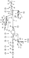
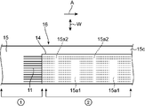
- It is a system diagram of the manufacturing process of the refusable type wear article It is a top view of the manufacturing situation of process 1 and process 2. It is a top view of the manufacturing situation of the process 3 to the process 7.
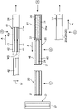
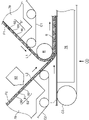
- FIG. 1 It is a schematic diagram of the core manufacturing apparatus. It is explanatory drawing of the process of manufacturing a core by laminating the core-side first nonwoven fabric and the core-side second nonwoven fabric. It is sectional drawing which shows the manufacturing process of a core, and shows the state before raising of the core side first nonwoven fabric and the core side second nonwoven fabric. It is sectional drawing which shows the manufacturing process of a core, and shows the state after raising of the core side first nonwoven fabric and the core side second nonwoven fabric. It is sectional drawing which shows the manufacturing process of a core, and shows the state which the core-side first nonwoven fabric and the core-side second nonwoven fabric support SAP.
- It shows how to form work-in-process. It is sectional drawing of the main part of the manufacturing process of a process 8 and a process 9, and shows the state of joining the absorber turned in a predetermined direction through a process 7 to a girth continuum. It is sectional drawing of the main part of the manufacturing process of a process 10, and shows the state that the extended part is folded back. It is sectional drawing of the main part of the manufacturing process of a process 11 to a process 13, and shows a state that a wearable article is folded in half.
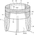
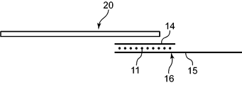
- the refusable type worn article 1 includes a waist member 10 arranged around the wearer's waist and an absorber 20 arranged from the back of the wearer to the front abdomen via the inseam. And have.
- the girth member 10 has elasticity that extends in the width direction and can be expanded and contracted in the width direction, and is provided at the girth body 16 (FIG. 4) arranged around the wearer's girth and at both ends 10c of the girth body 16 in the width direction. It has a male fastener (first engaging portion) 12 provided on a surface facing the skin surface side of the wearer.
- the extending direction of the waist circumference main body 16 (FIG. 4) in the waist circumference member 10 is defined as the waist circumference width direction (width direction).
- the direction substantially orthogonal to the direction is referred to as the waist circumference orthogonal direction (orthogonal direction).
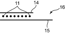
- the waistline main body 16 is joined to the inner sheet 14 (FIG. 4), the outer sheet 15 (FIG. 4), the inner sheet 14 and the outer sheet 15 while being sandwiched between the inner sheet 14 (FIG. 4) and the outer sheet 15 (FIG. 4). It has a member 11 (FIG. 4).
- the absorber 20 is a member mainly for absorbing body fluids such as urine and sweat.
- the absorber 20 is joined to the joint portion 10b (FIGS. 3 and 4) of the waist circumference member 10.
- the joint portion 10b is a central portion of the waist circumference member 10 in the waist circumference width direction and is a portion downwardly separated from the waist side edge.
- the absorber 20 extends orthogonally to the waistline from the joint 10b so as to be disposed from the back of the wearer through the inseam to the anterior abdomen.
- the absorber 20 has a female fastener (second engaging portion) 22 on the outer surface of the tip portion in the direction orthogonal to the waist circumference, which is opposite to the surface facing the skin surface side.
- the refusable type worn article 1 having such a configuration is folded in the final form (at the stage when the worn article is used for the first time) in a state where the male fastener 12 and the female fastener 22 are engaged with each other.
- the absorber 20 is folded in half in the direction orthogonal to the waist circumference, and the joint portion is formed in the waist circumference member 10.
- the male fastener 12 and the female fastener 22 are engaged with each other in a state where both side portions 10a, which are portions adjacent to each other in the waist width direction of 10b, are folded in the waist width direction.
- the wearer spreads the waistline member 10 of the refusable type worn item 1 assembled in the form of pants with the male fastener 12 and the female fastener 22 engaged, and inserts the leg to insert the leg into the pants.
- the worn article 1 is attached as described above.
- the male fastener 12 and the female fastener 22 are previously engaged with each other, but the engaged article 12 and 22 are disengaged and the worn article 1 is developed in the form shown in FIG. can do. Further, the engagement and disengagement of the fasteners 12 and 22 are repeated when the worn article 1 is adapted to the wearer and when the worn article 1 is replaced.
- the open type worn article is in a state in which the male fastener 12 and the female fastener 22 are not engaged in the final form (at the stage when the worn article is used for the first time). It is folded at. Specifically, in the open type worn article, for example, both side portions 10a of the waistline member 10 of the worn article in the developed form of FIG. 3 are folded in the waistline width direction so as to face the skin surface side of the absorber 20. In this state, the absorber 20 is folded in the direction orthogonal to the waist circumference so that the tip portion of the absorber 20 is located on the waist circumference member 10 side.
- both side portions 10a of the waist circumference member 10 are folded so as to be sandwiched between the joint portion 10b of the waist circumference member 10 and the absorber 20.
- the male fastener 12 and the female fastener 22 are not engaged.
- the open type worn article may include the unfolded form shown in FIG. 3 which is not folded.
- the girth member 10 has elasticity that extends in the girth width direction and expands and contracts in the girth width direction, and is arranged around the wearer's girth (FIG. 4) and both ends of the girth body 16 in the girth width direction. It has a male fastener 12 provided on a surface facing the skin surface side of the wearer in 10c.
- the waist circumference main body 16 has an inner sheet (FIG. 4 and the like) 14 described later, an outer sheet (FIG. 4 and the like) 15, and a waist circumference elastic member 11.
- the portion of the waist circumference main body 16 to which the absorber 20 is joined is the joint portion 10b.
- a part of the waist circumference elastic member 11 is located above the waist circumference orthogonal direction of the joint portion 10b.
- both side portions 10a of the waist circumference main body 16 are regions adjacent to the joint portion 10b in the waist circumference width direction.
- Both side portions 10a include both end portions 10c of the waist circumference main body 16 which are both ends in the waist circumference width direction.
- At least a part of both end portions 10c is a joint portion 15a2 (FIGS. 3 and 4) to which the male fastener 12 is joined.
- the waist circumference main body 16 has elasticity in the waist circumference width direction as a whole.
- the joint portion 10b of the waist circumference main body 16 is a portion where one end portion of the absorber 20 is arranged. Further, the joint portion 10b includes a core arrangement portion 15a1 in which the core 25 constituting a part of the absorber 20 is arranged (FIG. 2). Further, the joint portion 15a2 of the waist circumference main body 16 is a portion where the male fastener 12 is arranged.
- the core-arranged portion 15a1 has less or almost no elasticity in the waist width direction than the region excluding the core-arranged portion 15a1. That is, in the waist circumference main body 16, in the region other than the core arrangement portion 15a1, the elasticity in the waist circumference width direction is larger than that of the core arrangement portion 15a1. Further, in the joint portion 15a2, the elasticity in the waist width direction is smaller or almost the same as that in the region other than the joint portion 15a2. That is, in the waist circumference main body 16, in the region excluding the core arrangement portion 15a1 and the joint portion 15a2, the elasticity in the waist circumference width direction is larger than that of the joint portion 15a2. As a result, the waist circumference main body 16 has elasticity in the waist circumference width direction as a whole due to the elasticity in the waist circumference width direction in the region excluding the core arrangement portion 15a1 and the joint portion 15a2.
- the refusable type worn article 1 has a male fastener 12 and a female in the final form (at the stage when the worn article is used for the first time) in a state where the absorber 20 is temporarily fixed so as to be peelable in a folded state.
- the fasteners 22 are engaged with each other and folded into a pants-shaped form.
- the wearer wears the referable type worn article 1
- the wearer peels off the temporary fastener while the male fastener 12 and the female fastener 22 are engaged with each other, and the waist member of the worn article 1 is worn. 10 is pushed open, the legs are inserted, and the worn item 1 is attached like pants.
- the male fastener 12 and the female fastener 22 are disengaged from each other, and the worn article 1 in the deployed form can be worn as follows.
- the absorber 20 is arranged over a range from the back of the wearer to the anterior abdomen via the inseam in a state where the joint portion 10b of the waist circumference main body 16 is in contact with the back of the back. In this state, both side portions 10a adjacent to the joint portion 10b of the waist circumference main body 16 are extended to the outer surface of the tip portion of the absorber 20 located in the anterior abdomen. Then, the male fastener 12 provided on the waist circumference main body 16 and the female fastener 22 provided on the absorber 20 are engaged with each other, so that the wearable type worn article 1 is attached to the wearer.
- the upper edge of the waist circumference main body 16 in the direction perpendicular to the waist circumference is substantially linear along the waist circumference width direction.
- the leg circumference curved portion 15b for forming a leg hole along the shape of the leg circumference 15b (FIGS. 3 and 4). Etc.) are provided.
- the leg circumference curved portion 15b has a curved shape such that the length of the waist circumference main body 16 in the direction perpendicular to the waist circumference becomes longer from both side portions 10a toward the joint portion 10b.
- the waist circumference main body 16 includes an inner sheet 14 extending in the waist circumference width direction, an outer sheet 15 extending in the waist circumference width direction and covering an outer surface opposite to the surface of the inner sheet 14 facing the skin surface side. It has a waist circumference elastic member 11 having elasticity that can be expanded and contracted along the waist circumference width direction.
- the inner sheet 14 is, for example, a non-woven fabric sheet, which is a strip-shaped member extending in the waist width direction.
- One end of the absorber 20 is joined to the portion corresponding to the joint portion 10b of the inner sheet 14.
- the male fastener 12 extends in the direction orthogonal to the waist circumference on the surface of the inner sheet 14 facing the skin surface side at both ends 10c in the waist circumference width direction. Specifically, the male fastener 12 is joined to the inner sheet 14.
- the length of the male fastener 12 in the direction orthogonal to the waistline may be such that the engagement with the female fastener 22 is not easily disengaged. For example, if the length of the male fasina 12 in the orthogonal direction of the waist is about the same as the length of the inner sheet 14 in the orthogonal direction of the waist, the waist main body 16 is surely the same as the female fasner 22 of the absorber 20 over the entire length in the orthogonal direction of the waist. Can be engaged with.
- the outer sheet 15 is made of, for example, a non-woven fabric, and is a band-shaped member extending in the waist width direction like the inner sheet 14.
- the outer sheet 15 is arranged on the outer surface side of the inner sheet 14 opposite to the skin surface side, and covers the outer surface of the inner sheet 14 opposite to the surface facing the skin surface side.
- the planar shape of the inner sheet 14 is the same as the planar shape of the waist circumference main body 16 described above. As shown in FIG. 4, the upper edge of the inner sheet 14 in the direction orthogonal to the waist circumference is formed in a straight line along the waist circumference width direction. Further, the lower edge of the inner sheet 14 on the base side of the leg in the direction orthogonal to the waist circumference has a curved leg circumference curved portion 15b along the shape of the leg circumference. Both ends of the inner sheet 14 in the girth width direction are linear along the girth orthogonal direction.
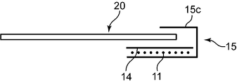
- the lower edge of the outer sheet 15 has a curved leg circumference curved portion 15b that follows the shape of the leg circumference on the base side of the leg, similarly to the inner sheet 14 in a plan view. Further, the outer sheet 15 has an extending portion 15c extending upward in the direction orthogonal to the waist circumference of the inner seat 14 in a state where the inner seats 14 are stacked so as to cover the waist circumference elastic member 11.
- the extension portion 15c is folded so as to cover the waist circumference elastic member 11 and the end portion of the absorber 20 to be joined to the waist circumference member 10 in the direction orthogonal to the waist circumference. It is joined to the inner sheet 14 and the absorber 20. This makes it possible to suppress the discomfort caused by the end portion of the absorber 20 coming into contact with the skin. Further, the end portion of the absorber 20 is not exposed, and the good appearance can be improved.
- the waistline elastic member 11 is attached to at least one of the inner sheet 14 and the outer sheet 15 in a state where the waistline elastic member 11 is linearly extended in the waistline width direction and is sandwiched between the inner sheet 14 and the outer sheet 15. It is joined.
- the waistline elastic member 11 is arranged in a range from the upper end edge of the inner sheet 14 to the leg circumference curved portion 15b on the base side of the leg in the region excluding the extension portion 15c.
- the waistline elastic member 11 is weakened in the weakened portions 15a1 and 15a2 described later.
- the curved portion 15b around the leg constitutes a part of the curved leg hole along the shape of the base of the leg.
- the waistline elastic member 11 adjacent to the leg circumference curved portion 15b elastically adheres a part of the peripheral edge portion of the leg hole to the upper part of the base of the leg to improve the wearing feeling.
- the waistline elastic member 11 adjacent to the leg circumference curve portion 15b may be curved so as to follow the curve of the leg circumference curve portion 15b.
- the waistline elastic member 11 is made of, for example, a material such as polyurethane, natural rubber, or a thermoplastic resin.
- the shape of the waistline elastic member 11 is, for example, a thread shape, a ribbon shape, a sheet shape, or the like.
- the elastic members, the three-dimensional gather elastic member 41, the absorber elastic member 21, and the like, which constitute the leg gather 31 described later, have the same material and shape.
- the waist elastic member 11 can be bonded to the inner sheet 14 and the outer sheet 15 by bonding with a hot melt adhesive or welding by heat sealing, but it is preferable that the body is ultrasonically welded. When ultrasonic welding is used, the flexibility of the inner sheet 14 and the outer sheet 15 can be maintained as compared with the case where an adhesive is used, and there is less crisp and stiff touch and less discomfort.
- the waistline elastic member 11 has elasticity in the waistline width direction. As a result, the waistline elastic member 11 elastically adheres the waistline body 16 of the waistline member 10 to the waistline.
- the waist circumference elastic member 11 is composed of a plurality of filamentous elastic members, extends in the waist circumference width direction of the waist circumference member 10, and is arranged at intervals in the waist circumference orthogonal direction.
- the waist elastic member 11 is weakened in the core arrangement portion 15a1 (also referred to as the weakened portion 15a1) of the joint portion 10b to which the absorber 20 of the waist circumference member 10 is joined (see FIG. 2). ).
- the region of the joint portion 10b is larger than the region of the core arrangement portion 15a1.
- the front surface sheet 24 and the back surface sheet are arranged in a state where the core 25 is arranged in the central portion in the waist circumference width direction and the leg gathers 31 are arranged along both edges in the waist circumference width direction. It is sandwiched between 26 and 26.
- the back surface sheet 26 is joined to the joint portion 10b of the waist circumference member 10.
- the waistline elastic member 11 is subjected to a weakening treatment.
- the waistline elastic member 11 is not weakened. ..
- a part of the waistline elastic member 11 is located above the waistline orthogonal direction of the joint portion 10b. That is, a part of the waist circumference elastic member 11 is arranged between the upper end edge of the waist circumference main body 16 in the direction orthogonal to the waist circumference and the joint portion 10b. Therefore, in the present embodiment, the waistline elastic member is formed on three sides of the joint portion 10b, both sides adjacent to the core arrangement portion 15a1 in the waist circumference width direction and the upper portion in the waist circumference orthogonal direction to the core arrangement portion 15a1. No weakening treatment is applied to 11.
- At least one of the waist circumference elastic members 11 is provided in an extended state in the portion of the joint portion 10b above the core arrangement portion 15a1 in the direction orthogonal to the waist circumference as in the present embodiment.
- the tip portion of the absorber 20 on the waist circumference member 10 side overlaps with the waist circumference elastic member 11 arranged on the upper portion. Therefore, just as the free end of the absorber 20 in the direction orthogonal to the waist circumference (the end opposite to the waist circumference member 10) can be expanded and contracted by the absorber elastic member 21 described later, the waist circumference member 10 side of the absorber 20 can be expanded and contracted.
- the tip portion can also be expanded and contracted by the waistline elastic member 11.
- the waist circumference elastic member 11 is subjected to a weakening treatment.
- the region of the joint portion 10b is larger than the region of the core arrangement portion 15a1, but the region of the joint portion 10b and the region of the core arrangement portion 15a1 may coincide with each other.
- the joint portion 15a2 to which the male fastener 12 is joined is at least a part of both end portions 10c of the waist circumference member 10.
- the region of both end portions 10c and the region of the joint portion 15a2 may coincide with each other.
- the region of the joint portion 15a2 and the region of the weakened portion coincide with each other, but the region of the weakened portion may be larger than the region of the joint portion 15a2.
- the weakening process is a process of weakening the elastic force of the waist circumference main body 16 by the elastic member.
- the weakening process also includes a process of invalidating the elastic force of the elastic member.
- the weakening treatment is performed, for example, by cutting a portion of the waistline elastic member 11 located in the core arrangement portion 15a1 and the joint portion 15a2. For example, a waist elastic member 11 that is joined to the inner sheet 14 and the outer sheet 15 at a portion other than the core arrangement portion 15a1 and the joint portion 15a2 and is not joined at the core arrangement portion 15a1 and the joint portion 15a2. By cutting, the core arrangement portion 15a1 and the joint portion 15a2 can be weakened.
- Cutting is performed, for example, by cutting the elastic member with a blade, or by applying heat to the elastic member to melt the elastic member. Since the elastic member is divided by the weakening treatment, the elastic force in the core arrangement portion 15a1 and the joint portion 15a2 is weakened.
- the weakening treatment includes not only the treatment of removing the elasticity by dividing the elastic member as described above, but also the modification of the elastic member so that the elasticity is lowered.
- the weakening treatment includes a method of intermittently joining an elastic member to a non-woven fabric and cutting the elastic member between the joints. As a result, the elastic force of the elastic member is weakened in the range where the elastic member is cut.
- the elastic force of the waist circumference main body 16 by the waist circumference elastic member 11 is weakened in the weakened portion 15a1 in which the absorber 20 is arranged and the weakened portion 15a2 in which the male fastener 12 is arranged. That is, the elastic force of the weakened portion 15a1 and the weakened portion 15a2 of the waist circumference main body 16 by the waist circumference elastic member 11 is weaker than the elastic force of the portion adjacent to the weakened portion 15a1 and the weakened portion 15a2 of the waist circumference main body 16 in the waist circumference width direction. ..
- the elastic force of the waist circumference main body 16 by the waist circumference elastic member 11 is weakened. Therefore, since the shrinkage of the core 25 joined to the weakened portion 15a1 of the waist circumference main body 16 can be suppressed, the back portion and the like can be reliably covered by the core 25.
- the elastic force of the waist circumference main body 16 by the waist circumference elastic member 11 is weakened. Therefore, the shrinkage of the male fastener 12 can be suppressed, and the engagement force between the male fastener 12 and the female fastener 22 can be suppressed from being impaired.
- the absorber 20 is a band-shaped member capable of absorbing body fluid such as urine, is joined to the joint portion 10b of the waist circumference main body 16, and extends from the joint portion 10b in the direction orthogonal to the waist circumference.
- the absorber 20 is arranged from the back of the wearer through the inseam to the anterior abdomen.
- the absorber 20 is the skin of the core 25 so as to sandwich the core 25 between the core 25 for absorbing body fluid, the surface sheet 24 provided on the skin surface side of the wearer of the core 25, and the surface sheet 24.
- the back surface sheet 26 provided on the outer surface side opposite to the surface side and the back surface sheet 26 provided on the outer surface opposite to the surface facing the skin surface side of the back surface sheet 26 and were detachably engaged with the male fastener 12. It has a female fastener 22 and.
- the absorber 20 further includes an absorber elastic member 21, a leg gather 31, a three-dimensional gather 40, and an indicator 50.
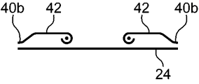
- the surface sheet 24 is a band-shaped sheet extending in the direction orthogonal to the waist circumference, and is provided on the skin surface side of the wearer with respect to the core 25.
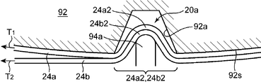
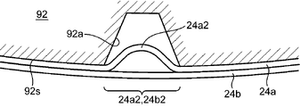
- the surface sheet 24 is formed by laminating two surface-side first nonwoven fabrics 24a and surface-side second nonwoven fabrics 24b (FIGS. 11, 12, etc.) having substantially the same size of liquid permeability, and surface-side first nonwoven fabrics 24a. It is formed by joining the second non-woven fabric 24b on the surface side and the surface side.
- the surface-side first nonwoven fabric 24a has a surface facing the wearer's skin surface side when worn, and a plurality of uneven shapes 20a are provided on the surface facing the skin surface side.
- the back surface of the front surface side first nonwoven fabric 24a has an uneven shape opposite to the uneven shape 20a on the front surface.
- the shape of the concave portion and the convex portion forming the concave-convex shape 20a is not particularly limited, and is, for example, a circular shape, an elliptical shape, a polygonal shape, or the like in a plan view. Further, the size of the concave portion and the convex portion may be such that it can suppress the sticking to the skin surface due to contact and give a pleasant sensation to the skin surface. be.
- the uneven shape 20a is provided on the surface-side first nonwoven fabric 24a on the skin surface side. Therefore, the convex portion of the concave-convex shape 20a elastically makes point contact with the skin surface of the wearer, and air can pass through the concave portion, and the air permeability is good. Therefore, according to the surface sheet 24, it is possible to improve the feel of the skin as compared with the case where the surface sheet 24 and the skin surface are in surface contact with each other. Even after the absorber 20 has absorbed body fluids such as urine and sweat, the convex portion of the surface sheet 24 and the skin surface wet with urine or the like are in point contact with each other, and further, there is breathability due to the concave portion. Thereby, the discomfort of the tactile sensation on the skin surface can be alleviated.
- the surface-side second nonwoven fabric 24b is joined to the outer surface of the surface-side first nonwoven fabric 24a opposite to the surface facing the skin surface side.
- the surface-side second nonwoven fabric 24b has a shape with gentler undulations than the uneven shape 20a of the surface-side first nonwoven fabric 24a.
- the surface of the surface-side second nonwoven fabric 24b facing the skin surface side is, for example, a flat surface.
- the undulations of the surface-side second nonwoven fabric 24b are smaller than the undulations of the surface-side first nonwoven fabric 24a. Therefore, the ease of stretching of the surface-side second nonwoven fabric 24b in the surface direction is smaller than that of the surface-side first nonwoven fabric 24a.
- the elongation of the surface-side first nonwoven fabric 24a is restrained by the surface-side second nonwoven fabric 24b, and the uneven shape 20a of the surface-side first nonwoven fabric 24a is maintained.
- the concave portion of the concave-convex shape 20a of the surface-side first nonwoven fabric 24a is joined to the flat surface of the surface-side second nonwoven fabric 24b, and the shape of the convex portion of the concave-convex shape 20a is formed by joining the concave portion. Be maintained. For example, even when the wearer presses the concave-convex shape 20a by contact, the convex portion is not easily deformed, and the good touch to the touch can be maintained by the point contact with the convex portion.
- the surface sheet 24 is formed of two non-woven fabrics (first surface-side non-woven fabric 24a and front-side second non-woven fabric 24b), but the number of non-woven fabrics may be three or more.
- the uneven shape 20a is provided on the surface of at least one non-woven fabric facing the skin surface side among the plurality of non-woven fabrics. Therefore, the uneven shape 20a may be provided on all the nonwoven fabrics constituting the surface sheet 24.
- the surface sheet 24 may be formed from one non-woven fabric.
- the uneven shape 20a is provided on the surface of one piece of non-woven fabric facing the skin surface side.
- adhesion using a hot melt adhesive or welding by heat sealing can be used, but ultrasonic welding is preferable.
- ultrasonic welding is used for the bonding, the flexibility of the surface sheet 24 can be maintained as compared with the case where an adhesive is used, and there is less crisp and stiff touch and less discomfort.
- the aspect of the surface sheet 24 also includes an embodiment in which the surface of the surface-side first nonwoven fabric 24a facing the skin surface side is a flat surface.
- the surface sheet 24 may be formed of only one non-woven fabric having a flat surface shape. That is, the surface sheet 24 may be formed from only the flat surface-shaped first nonwoven fabric 24a without omitting the surface-side second nonwoven fabric 24b.
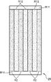
- the core 25 is a rectangular strip-shaped sheet extending in the direction orthogonal to the waistline in a plan view.
- a constriction may be formed at the center position of the core 25 in the direction orthogonal to the waistline at both edges in the waistline width direction.
- the constriction is formed by recessing both edges in the waist width direction in order to arrange the core 25 around the wearer's legs without gaps.
- the constriction has a curved shape for extending the curve of the above-mentioned curved portion 15b around the leg.
- the core 25 will be described in detail in the manufacturing method described later, but as shown in FIG. 5A, the core 25 is manufactured by being continuously connected in the direction orthogonal to the waist circumference.
- a cut region Cut is provided between the continuous cores 25.
- the continuous core 25 is cut at the cutting line N of the cut region Cut and divided into one core 25 having a predetermined length of 25 L.
- the distribution density of SAP in the cut region Cut is lower than the distribution density of SAP in the holding region R2 described later.
- the cut region Cut of the core-side first nonwoven fabric S1 and the core-side second nonwoven fabric S2 hardly retains SAP.
- SAP may not be supported at all in the cut region Cut.
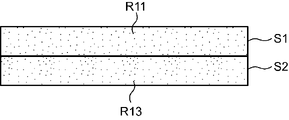
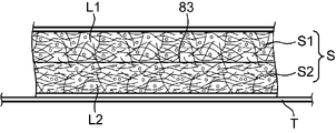
- the core 25 is a superabsorbent polymer (SAP) supported on two core-side first nonwoven fabrics S1 and core-side second nonwoven fabric S2, and these core-side first nonwoven fabric S1 and core-side second nonwoven fabric S2. It is formed by.
- SAP is a water-absorbent substance having water absorption, and for example, sodium polyacrylate or the like is used.
- the core 25 further has a core-side second nonwoven fabric S2 laminated on the core-side first nonwoven fabric S1 so as to face the core-side first nonwoven fabric S1 via SAP.
- a raised fiber layer is formed on the facing surfaces of the core-side first nonwoven fabric S1 and the core-side second nonwoven fabric S2 to form a gap for supporting SAP.
- the amount of SAP supported is increased as compared with the case where the one-layer core-side first nonwoven fabric is provided, and urine produced by SAP is used. It is possible to increase the amount of absorption such as.
- the core-side first nonwoven fabric S1 carries SAP so that the first low-density region R11 and the holding region R2 are formed.
- the first low-density region R11 is arranged adjacent to both ends of the holding region R2 in the direction orthogonal to the waistline in the direction orthogonal to the waistline. Further, the first low density region R11 is a region from the end portion of the holding region R2 in the circumferential direction orthogonal direction to the cutting line N in the cut region Cut of FIG. 5A.
- the distribution density of SAP in the first low density region R11 is lower than the distribution density of SAP in the retention region R2.
- the first low density region R11 does not have to carry SAP.
- the holding region R2 is a region in which SAP is supported so as to have a predetermined water absorption performance such as urine. Then, the core-side first nonwoven fabric S1 exhibits preset water absorption performance as a whole of the first low density region R11 and the holding region R2.
- the holding region R3 of the core-side second nonwoven fabric S2 is arranged at a position overlapping with the holding region R2 of the core-side first nonwoven fabric S1 in a plan view.
- the third low-density region R13 of the core-side second nonwoven fabric S2 is arranged at a position overlapping with the first low-density region R11 of the core-side first nonwoven fabric S1 in a plan view.
- the distribution density of SAP in the third low density region R13 is lower than the distribution density of SAP in the holding region R2 and the holding region R3.
- the third low density region R13 does not have to carry SAP.
- the distribution density of SAP in the holding region R3 is set to have a predetermined water absorption performance such as urine.
- the distribution density of SAP in the third low density region R13 and the entire holding region R3 of the core side second nonwoven fabric S2 is set so as to exhibit preset water absorption performance.
- the density of SAP in the holding region R3 may be the same as or different from that in the holding region R2.
- the density of SAP in the third low density region R13 may be the same as or different from that of the first low density region R11.
- the core-side first nonwoven fabric S1 is arranged on the skin surface side of the wearer of the worn article 1, and the core-side second nonwoven fabric S2 is laminated on the back surface side of the core-side first nonwoven fabric S1.
- the two core-side first nonwoven fabrics S1 and the core-side second nonwoven fabric S2 are laminated so that the raised fiber layers supporting the SAP face each other. This makes it possible to suppress the dropout of SAP. That is, high-density fibers are entangled in the unraised outer portion on the outer surface side of the core-side first nonwoven fabric S1 and the core-side second nonwoven fabric S2. The SAP is supported in the core-side first nonwoven fabric S1 and the core-side second nonwoven fabric S2 by this outer portion.
- the first non-woven fabric S1 on the core side is formed while holding SAP. Since the absorption performance per unit volume of SAP is higher than the absorption performance per unit volume of fluff pulp, the amount of fluff pulp used when fluff pulp is used can be reduced. Therefore, the thickness of the core 25 can be made thinner than that of the non-woven fabric formed only from the amount of fluff pulp required for a predetermined absorption performance. Since the thickness of the worn article 1 provided with the core-side first non-woven fabric S1 is also thin, it is easy to fit the worn article 1 according to the body shape of the wearer's waist circumference, and the fit of the worn article 1 can be improved.
- the thickness of the core 25 can be made thinner than that of a non-woven fabric formed only from the amount of fluff pulp required for a predetermined absorption performance.
- the thickness of the worn article 1 can also be reduced, so that the worn article 1 can be easily adapted to the body shape of the wearer's waist and worn. The fit of the article 1 can be improved.
- the holding region R2 has poor flexibility because the distribution density of SAP is higher than that of the first low density region R11.
- the first low density region R11 has higher flexibility than the holding region R2 because the distribution density of SAP is lower than that of the holding region R2. Therefore, the core 25 having the first low density region R11 tends to change its shape.
- both ends of the holding region R2 in the direction orthogonal to the waist circumference are arranged facing the front abdomen and the back of the wearer, respectively.
- a first low-density region R11 having a SAP distribution density lower than that of the holding region R2 is arranged at a portion adjacent to both ends of the holding region R2 in the waist-orthogonal direction.
- the portion of the core 25 in which the first low-density region R11 is arranged is flexibly deformed along the body shapes of the anterior abdomen and the posterior back, and the portion abuts on the anterior abdomen and the posterior back with a soft touch. , It is possible to improve the wearing feeling of the worn article 1.
- the worn article 1 may be manufactured by combining the core 25 shown in FIGS. 5A to 5C and the surface sheet 24 having the uneven shape 20a.
- the uneven shape 20a of the surface sheet 24 can improve the air permeability and the touch. Further, even after the absorption of the body fluid, the uneven shape 20a of the surface sheet 24 can maintain the good breathability and the good touch.
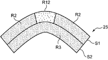
- the arrangement of the low density region in the core 25 is not limited to the above-mentioned form, and may be, for example, the arrangement as shown in FIGS. 6A to 6D.
- the first low-density region R11 is arranged adjacent to both ends of the holding region R2 in the waist-orthogonal direction and adjacent to both ends in the waist-orthogonal direction, and the second low density region R2 is low.
- the density region R12 is arranged so as to be sandwiched by the holding region R2 in the waist width direction.
- the holding region R2 is a region in which SAP is supported so as to have a predetermined water absorption performance such as urine.
- the distribution density of SAP in the second low density region R12 is lower than the distribution density of SAP in the retention region R2.
- the second low density region R12 does not have to carry SAP.
- the distribution density of SAP in the second low density region R12 may be the same as or different from the distribution density of SAP in the first low density region R11. Then, the core-side first nonwoven fabric S1 exhibits preset water absorption performance as a whole of the first low density region R11, the second low density region R12, and the holding region R2.
- the second low density region R12 is located at the center of the core 25 in the waist width direction along the waist orthogonal direction. It is provided so as to be continuous.
- the holding region R2 is provided so as to be adjacent to both sides of the second low density region R12 in the waist circumference width direction.
- the amount of SAP held in the second low density region R12 is smaller than the amount of SAP held in the holding region R2. Therefore, the flexibility of the core 25 in the second low density region R12 is higher than the flexibility of the core 25 in the holding region R2. Therefore, the core 25 can be easily deformed along the body shape, and the stiff feeling of the core 25 can be suppressed, so that the fit of the worn article 1 can be improved.
- the second low density region R12 continuously extends in the waist orthogonal direction at the central portion of the core 25 in the waist width direction.
- the core 25 is formed over the formation range of the second low density region R12 in the direction orthogonal to the waist circumference. Can be deformed to fit the wearer's body shape, and the fit of the worn article can be improved.
- the core 25 is substantially symmetrical with respect to the second low density region R12 in the central portion. It is easy to transform into an inverted V-shaped bent shape. Therefore, when the wearer wears the worn article, the core 25 extending from the back back to the front abdomen via the inseam is deformed as shown in FIG. 6C according to the shape of the wearer's inseam. Therefore, the wearing feeling of the worn article 1 can be further improved. As shown in FIG. 6D, the core 25 can be deformed into a V-shaped bent shape substantially symmetrically with the second low density region R12 as the center. In this case as well, the core 25 is less bulky between the lower crotch parts, and the wearing feeling of the worn article 1 can be improved.
- the core 25 can effectively absorb urine or the like by using the holding regions R2 adjacent to both sides of the second low density region R12 in the waist circumference width direction.
- the second low density region R12 is located at the center of the core 25 in the waist width direction, that is, the inseam. It is provided at a position where a relatively large amount of urine or the like is received. Therefore, there is a high possibility that urine or the like will be guided to the second low density region R12 and the holding region R2 adjacent to the second low density region R12 in the waist circumference width direction.
- Urine and the like can be diffused along the low density region R12.
- the urine or the like diffused along the second low density region R12 is also absorbed in the second low density region R12 and the holding region R2 adjacent thereto in the waist circumference width direction.
- a wider range of the holding region R2 is used by diffusing urine or the like as compared with the case where the second low density region R12 does not exist (the case where the density of SAP is constant over the entire holding range). It is possible to quickly absorb urine and the like. Therefore, the sticky feeling on the skin surface due to urine or the like can be more quickly eliminated to alleviate the discomfort.
- the second low density region R12 can be used as a region for the expansion of SAP in the holding region R2, excessive adhesion of the absorber 20 to the skin surface can be suppressed. Therefore, the sticky feeling on the skin surface due to urine or the like can be more quickly eliminated and the discomfort can be alleviated.
- the worn article 1 having the core 25 of FIGS. 6A to 6D is attached around the waist by engaging the male fastener 12 and the female fastener 22. Then, in a state where the absorber 20 is in close contact with the inseam, the flexibility of the second low density region R12 of the core 25 before absorption of the body fluid can improve the feeling of close contact with the inseam. Further, even after the absorption of the body fluid, the expansion space of the SAP can be secured by the second low density region R12 of the core 25, so that the core 25 can be suppressed from expanding to the skin surface side more than necessary. It can be done and can maintain good touch.
- the worn article 1 may be manufactured by combining the core 25 shown in FIGS. 6A to 6D and the surface sheet 24 having the uneven shape 20a.
- the worn article 1 is in a state where the absorber 20 is in close contact with the inseam, and before the absorption of the body fluid, the inseam is due to the uneven shape 20a of the surface sheet 24 and the second low density region R12 of the core 25. It is possible to improve the air permeability and the touch while improving the adhesion to the skin. Further, even after the absorption of the body fluid, the expansion space of the SAP can be secured by the second low density region R12 of the core 25, so that the core 25 can be suppressed from expanding to the skin surface side more than necessary. In addition, the uneven shape 20a of the surface sheet 24 can maintain good breathability and softness.
- the second low density region R12 and the holding region R2 are not limited to being formed by adjusting the amount of SAP supported on the core-side nonwoven fabric.
- the space formed by dividing the core-side nonwoven fabric in which the holding region R2 is formed and separating the divided portions in the width direction can be used as the second low-density region R12.
- the portion where the gap for holding the SAP is reduced by pressing the surface (the surface subjected to the brushed treatment) of the core-side non-woven fabric of the holding region R2 and crushing the fibers in the brushed state is designated as the second low density region R12. It can also be used.
- the core-side second nonwoven fabric S2 has only the third low-density region R13 as the low-density region.
- both of the two core-side nonwoven fabrics S1 and S2 may have a first low density region R11, a second low density region R12, and a holding region R2.
- the core-side first nonwoven fabric S1 has a first low-density region R11 provided at both ends of the core-side first nonwoven fabric S1 and a second low-density region R12 between both first low-density regions R11.
- the core-side second nonwoven fabric S2 has a third low-density region R13 provided at both ends of the core-side second nonwoven fabric S2, and a second low-density region R12 between both third low-density regions R13.
- the second low-density region R12 of the first core-side nonwoven fabric S1 and the second low-density region R12 of the core-side second nonwoven fabric S2 may be arranged at different positions in a plan view, or may overlap in a plan view. It may be arranged at a position.
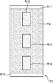
- the second low density region R12 of FIGS. 6A to 6D may have the form shown in FIGS. 7A to 7C, for example. Regarding the second low density region R12 of FIGS. 7A to 7C, only the differences from FIGS. 6A to 6D will be mainly described.
- the first low-density region R11 is arranged adjacent to both ends of the holding region R2 in the waist-orthogonal direction in the waist-orthogonal direction, and in the core-side first nonwoven fabric S1 in the waist-width direction.
- a plurality of second low-density regions R12 are intermittently provided in the central portion along the girth orthogonal direction.
- the holding regions R2 are provided adjacent to the waist circumference orthogonal directions of the second low density region R12 at both ends in the waist circumference orthogonal direction. That is, in the core-side first nonwoven fabric S1, both ends of the second low-density region R12 in the direction orthogonal to the waistline are closed by the holding region R2. As a result, the holding region R2 can be used as a weir for the second low density region R12. Therefore, according to the configuration shown in FIG. 7A, it is possible to prevent urine or the like from being guided to the outside of the core 25 in the direction orthogonal to the waist circumference by the second low density region R12.
- the first low-density region R11 is arranged adjacent to both ends of the holding region R2 in the waist-orthogonal direction in the waist-orthogonal direction and in the waist-width direction.
- the second low-density region R12 is provided on both sides of the second low-density region R12 in the girth width direction.
- the three second low-density regions R12 extend parallel to each other in the direction orthogonal to the waist circumference.
- the two added second low-density regions R12 facilitate the diffusion of urine or the like spread on the surface of the core 25 over the entire core 25, and further improve the flexibility of the core 25 in the orthogonal direction around the waist.
- the first low-density region R11 is arranged adjacent to both ends of the holding region R2 in the orthogonal direction of the waist in the orthogonal direction of the waist, and the first non-woven fabric S1 on the core side is arranged in the width direction of the waist.
- the second low density region R12 shown in FIG. 7B provided at the central position is not provided. That is, the holding region R2 is provided at the center position of the core-side first nonwoven fabric S1 in the waist circumference width direction, and the second low density regions R12 are provided on both sides of the center position in the waist circumference width direction.
- the two second low-density regions R12 extend parallel to each other in the direction orthogonal to the waist circumference.
- the two second low-density regions R12 make it easier to diffuse urine and the like over the entire core 25 than the one second low-density region R12 shown in FIG. 6A, and further, the core 25 is more flexible in the waist width direction. Sex also improves.
- the core 25 is substantially symmetrically V-shaped with the central portion in the waist width direction in which the second low density region R12 is arranged as the center. Alternatively, it can be easily deformed into an inverted V-shaped bent shape. Further, also in the example shown in FIG. 7C, the core 25 is substantially symmetrically bent into a U-shape or an inverted U-shape due to the provision of the two second low-density regions R12 separated from the central portion in the waist width direction. It is easy to transform it into a deformed shape.
- the extending direction of the second low density region R12 is not limited to the direction orthogonal to the waist circumference.
- the second low density region R12 may be sandwiched by the holding region R2 in the waist width direction along the waist width direction in the core 25.
- urine or the like is diffused in the waist width direction along the second low density region R12 and is adjacent to the second low density region R12. It can also be absorbed in the holding region R2.
- the holding region R2 since the holding region R2 is adjacent to the end portion in the waist circumference width direction in the second low density region R12, the holding region R2 can be used as a weir. Therefore, it is possible to prevent urine or the like from being guided to the outside of the core 25 in the waist width direction by the second low density region R12.
- the second low density region R12 may have a portion extending along the waist circumference orthogonal direction and a portion extending along the waist circumference width direction.
- the second low density region R12 has a portion extending along the waist circumference orthogonal direction in the central portion of the core 25 in the waist circumference width direction, and a portion extending in the waist circumference orthogonal direction and branching in the waist circumference width direction. You may.
- urine or the like can be diffused along the second low density region R12 in both the waist circumference orthogonal direction and the waist circumference width direction, and the urine and the like can be rapidly absorbed in the holding region R2.
- the regions having different distribution densities of SAP are not limited to the low density regions R11, R12 and R13, and the holding regions R2 and R3.
- the core 25 may be provided with a plurality of regions having different distribution densities selected from the distribution regions from 0 to the distribution density of SAP in the retention region R2 with the retention region R2 as a reference. good.
- both of the two core-side nonwoven fabrics carry SAP, but only one of the core-side nonwoven fabrics supports SAP, and the remaining core-side nonwoven fabric does not have to support SAP. .. Further, it may contain fluff pulp.
- the core-side nonwoven fabric containing fluff pulp is arranged on the skin surface side of the wearer, and the core-side first nonwoven fabric S1 shown in FIGS. 5A to 5C is provided. It may be arranged on the side opposite to the skin surface side.
- the fluff pulp of the core-side nonwoven fabric on the skin surface side absorbs the body fluid faster than the SAP
- the SAP of the core-side first nonwoven fabric S1 on the opposite side further absorbs the body fluid absorbed by the fluff pulp.
- the core-side nonwoven fabric containing the fluff pulp is arranged in the upper layer in the same manner as described above, and the core-side non-woven fabric shown in FIGS. 6A to 6D and 7A to 7C is shown in the core side.
- Nonwoven fabric S1 may be arranged in a lower layer.
- the method of supporting SAP on the core-side nonwoven fabric is not limited to the method of supporting SAP on the fiber layer of the core-side nonwoven fabric raised to form a gap for supporting SAP.
- an adhesive may be applied to the surface of the core-side nonwoven fabric, SAP may be sprayed on the applied adhesive, and the SAP may be placed on the surface of the core-side nonwoven fabric.
- the amount of adhesive applied for the low density areas R11, R12, R13 per unit area is less than the amount of adhesive applied for the holding areas R2, R3 per unit area.
- the number of core-side nonwoven fabrics forming the core 25 is not limited to two, and may be formed from one core-side nonwoven fabric.
- the back surface sheet 26 is a rectangular strip-shaped sheet extending in the direction orthogonal to the waist circumference. Further, the back surface sheet 26 is provided on the outer surface of the core 25 opposite to the surface facing the skin surface side, and sandwiches the core 25 with the front surface sheet 24.
- the back surface sheet 26 has a liquid impermeable sheet 26a facing the core 25 and an outer layer sheet 26b covering the outer surface of the liquid impermeable sheet 26a opposite to the surface facing the core 25.
- the liquid impermeable sheet 26a is a strip-shaped sheet that has water repellency and does not allow urine or the like to permeate.
- the liquid impermeable sheet 26a is formed of a non-woven fabric made of, for example, polypropylene, polyethylene or the like.
- the liquid impermeable sheet 26a is preferably breathable.
- the core 25 is joined to the liquid impermeable sheet 26a in a state where the core 25 is arranged so as to be within the range of the waist circumference width direction and the waist circumference orthogonal direction of the liquid impermeable sheet 26a. Since the liquid impermeable sheet 26a is provided on the outer surface of the core 25 opposite to the surface facing the skin surface side in this way, the liquid impermeable sheet 26a is impermeable even when urine or the like cannot be completely absorbed by the core 25. It is possible to suppress the outflow of urine or the like to the outside of the sheet 26a.
- the liquid impermeable sheet 26a has a rectangular shape in the example shown in FIG.
- the liquid impermeable sheet 26a may have a leg circumference curved portion formed at the center position in the waist circumference orthogonal direction at both edges of the liquid impermeable sheet 26a in the waist circumference width direction in a plan view.
- the leg circumference curved portion is formed by recessing both edge portions in the waist circumference width direction in order to arrange the liquid impermeable sheet 26a around the wearer's legs without gaps.
- the leg gather 31 is an elastic member corresponding to the base of the leg when the wearer wears the worn article 1.
- the leg gathers 31 are provided along both edges of the liquid impermeable sheet 26a in the waist width direction, substantially as a whole in the waist circumference orthogonal direction of the liquid impermeable sheet 26a.
- the leg gather 31 is arranged between the liquid impermeable sheet 26a and the surface sheet 24 in an extended state in the direction orthogonal to the waist circumference, and is joined to at least one of the liquid impermeable sheet 26a and the surface sheet 24.
- adhesion using a hot melt adhesive or welding by heat sealing can be used, but ultrasonic welding is preferable.
- the leg gather 31 may be arranged between the liquid impermeable sheet 26a and the outer layer sheet 26b and may be joined to at least one of them.
- the absorbent body elastic member 21 is provided at the free end (the end opposite to the waist circumference member 10) of the liquid impermeable sheet 26a in the direction orthogonal to the waist circumference, and has elasticity that allows expansion and contraction in the waist circumference width direction. Therefore, in the absorber 20 having the liquid impermeable sheet 26a, the tip portion on the side opposite to the side joined to the waist circumference member 10 can be expanded and contracted in the waist circumference width direction. Further, as described above, the waist circumference member 10 can also be expanded and contracted in the waist circumference width direction by the waist circumference elastic member 11.
- both the waist member 10 and the tip of the absorber 20 can be expanded and contracted in the waist width direction according to the length of the wearer's waist, so that the male fastener 12 of the waist member 10 and the female fastener of the absorber 20 can be expanded and contracted.
- the absorber elastic member 21 is not an essential configuration. Even when the absorber elastic member 21 is omitted, since the waistline member 10 has elasticity in the waistline width direction, the fit of the worn article 1 can be improved.
- the outer layer sheet 26b is a sheet extending in the direction orthogonal to the waist circumference and formed of a non-woven fabric, and is opposite to the surface of the liquid impermeable sheet 26a facing the skin surface side in a state of covering the liquid impermeable sheet 26a from the outer surface side. It is attached to the outer surface. Therefore, it is possible to improve the appearance of the worn article 1 from the outside and the feel of the worn article 1.
- the outer layer sheet 26b has a rectangular shape in the example shown in FIG. 4 and the like.
- the outer layer sheet 26b may have a leg circumference curved portion formed at the center position in the waist circumference orthogonal direction at both edge portions in the waist circumference width direction of the outer layer sheet 26b in a plan view. In this case, the leg circumference curved portion is formed by recessing both edge portions in the waist circumference width direction in order to arrange the outer layer sheet 26b around the wearer's leg without a gap.
- the liquid impermeable sheet 26a and the outer layer sheet 26b can be provided with curved portions around the legs. Further, as described above, a leg circumference curved portion 15b is provided on the lower edge of the leg circumference member 10 on the base side. In this case, as shown in FIGS. 1 and 2, these liquid-impermeable sheets are assembled by engaging the male fastener 12 of the waist circumference member 10 and the female fastener 22 of the absorber 20 to assemble the worn article 1.
- the leg circumference curved portion of the outer layer sheet 26b and the leg circumference curved portion 15b of the waist circumference member 10 can form a curved leg hole arranged along the entire circumference of the base of the leg.
- peripheral edge portion of the leg hole is elastically adhered to the base of the leg over the entire circumference by the leg gather 31 and the waistline elastic member 11 arranged in the vicinity of the leg circumference curved portion 15b. Thereby, the wearing feeling can be improved.
- the female fastener 22 is provided on the outer surface of the outer layer sheet 26b at the tip opposite to the waist member 10 in the direction orthogonal to the waist.
- the female fastener 22 is provided at the tip of the outer layer sheet 26b over substantially the entire circumference in the waist width direction.
- the length of the female fasina 22 in the girth orthogonal direction may be, for example, about the same as the length of the male fasna 12 in the girth orthogonal direction, or may be longer than the length of the male fasna 12 in the girth orthogonal direction.
- the female fastener 22 is provided over substantially the entire waist circumference width direction of the tip portion of the outer layer sheet 26b. Therefore, by expanding and contracting the waist circumference member 10 in the waist circumference width direction, the male fastener 12 can be engaged with an arbitrary position in the waist circumference width direction of the female fastener 22, and the degree of freedom in selecting the engagement position is large. Therefore, it is easy to adjust the engagement position between the waist circumference member 10 and the absorber 20 according to the length of the waist circumference of each wearer, and the fit can be improved.
- the indicator 50 changes color according to the amount of urine absorbed by the core 25, indicating that the wearer has urinated.
- the indicator 50 is a surface of the outer layer sheet 26b facing the skin surface side, and extends in the direction orthogonal to the waist circumference at the central portion of the outer layer sheet 26b in the waist circumference width direction.
- an adhesive that changes color according to the amount of absorbed urine or the like is used.
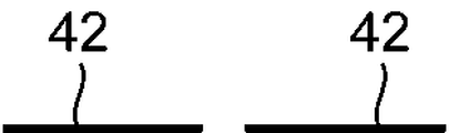
- the three-dimensional gather 40 is provided on the surface of the surface sheet 24 facing the skin surface side.
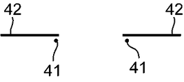
- the three-dimensional gather 40 has a pair of rising flaps 42 and a three-dimensional gather elastic member 41 provided on each of the rising flaps 42.
- the rising flap 42 extends in the direction orthogonal to the waist circumference and is joined to both edges of the surface sheet 24 in the waist circumference width direction.
- one edge portion (for example, the right edge portion) of each rising flap 42 in the waist width direction is joined to one edge portion (for example, the right side edge portion) of the surface sheet 24.
- Each three-dimensional gather elastic member 41 is joined to the other edge portion (for example, the left edge portion) of the rising flap 42 in the waist circumference width direction in an extended state.
- each rising flap 42 In a state where the absorber 20 is curved in the direction orthogonal to the waist circumference along the wearer's inseam, the other edge portion (for example, the left edge portion) in the waist circumference width direction of each rising flap 42 is attached with the three-dimensional gather elastic member 41. By being contracted by the force, each rising flap 42 stands up with respect to the surface sheet 24. When worn, the rising flap 42 elastically adheres to the back, inseam, anterior abdomen, and the like. Therefore, it is possible to suppress the outflow of urine or the like to the outside of the worn article 1.
- the lengths of the female fastener 22 in the waist width direction and the waist orthogonal direction are set so that an engaging force capable of engaging with the male fastener 12 can be obtained so that the waist member 10 and the absorber 20 are not deployed when worn. It suffices if it is set.
- the female fastener 22 may be provided only in the central portion in the waist circumference width direction at the tip end portion of the outer layer sheet 26b, or may be provided in two portions on both side portions in the waist circumference width direction.
- waist circumference member 10 and the absorber 20 can be engaged with each other, and a female fastener 22 may be provided on the waist circumference member 10 and a male fastener 12 may be provided on the absorber 20.
- back surface sheet 26 may be formed only from the liquid impermeable sheet 26a.
- a transfer sheet (not shown) may be interposed between the surface sheet 24 and the core 25. This transfer sheet rapidly diffuses urine or the like along the surface of the core 25 and prevents urine or the like absorbed by the core 25 from leaking from the surface sheet 24.
- the absorber 20 is folded in half in the waist circumference orthogonal direction, and both side portions 10a located on both sides of the joint portion 10b in the waist circumference member 10 are in the waist circumference width direction.
- the male fastener 12 and the female fastener 22 are engaged with each other in the folded state.
- the above-mentioned refusable type worn article 1 has a pants-type form because the female fastener 22 is engaged with the male fastener 12 in the initial state, and the wearer wears the pants. It is possible to wear items to be worn.
- both side portions 10a of the waist circumference member 10 project with respect to the absorber 20 arranged at the joint portion 10b of the waist circumference member 10.
- the both side portions 10a can be directed toward the tip end portion of the absorber 20 along the waist circumference of the wearer, and can be brought into contact with the back surface sheet 26 of the absorber 20 arranged along the inseam portion of the wearer.
- the male fasteners 12 at both ends 10c of the waist circumference member 10 in the waist circumference width direction are engaged with the female fasteners 22 of the back sheet 26 to support the refusable type worn article 1 around the waist circumference, whereby the absorber 20 is formed. It is pulled up and the absorber 20 comes into close contact with the wearer's inseam.
- the MD (Machine Direction) direction A is the transport direction of the sheet or the like
- the CD (Cross Direction) direction W is the direction substantially orthogonal to the length direction A.
- Step 1 to Step 2 are examples of a step of manufacturing a girth continuum in which a plurality of girth bodies 16 are continuous in a cross-flow state as shown in FIG.
- the MD direction A coincides with the waist circumference width direction
- the CD direction W coincides with the waist circumference orthogonal direction.
- Step 1 the continuous body of the outer sheet 15 in which the plurality of outer sheets 15 are continuous is conveyed in the MD direction A (see FIG. 17A), and the waistline elastic member 11 is placed on the continuous body of the outer sheet 15 in the MD direction A. They are arranged linearly along the line (see FIG. 17B).
- the waistline elastic members 11 are arranged at intervals in the direction orthogonal to the waistline on the lower side of the outer sheet 15 with a space from the upper end edge.
- a continuous body of the continuous inner sheets 14 of the plurality of inner sheets 14 is conveyed in the MD direction A, and the continuous inner sheets 14 are continuously covered with the waistline elastic member 11 from above.
- the body is placed on the continuum of the outer sheet 15.
- the continuum of the inner sheet 14 is positioned so that the upper side of the outer sheet 15 is exposed and is joined while covering the continuum of the outer sheet 15.
- the extending portion 15c is formed by the portion where the outer sheet 15 is exposed.
- the waistline elastic member 11 is linearly arranged along the MD direction A on the continuum of the outer sheet 15.
- the waistline elastic members 11 arranged at the lower end edge of the inner sheet 14 are arranged in a curved shape along the curve of the leg circumference curved portion 15b formed in the step 8 described later. You may.
- the waistline elastic member 11 arranged at the lower end edge of the inner sheet 14 may be arranged on the outer sheet 15 along a trajectory of a substantially sine wave meandering in the MD direction A.
- the waistline elastic member 11 is sandwiched between the continuum of the outer sheet 15 and the continuum of the inner sheet 14 in an extended state, and is joined to at least one of the continuum of the outer sheet 15 and the continuum of the inner sheet 14.
- adhesion using a hot melt adhesive or welding by heat sealing can be used, but ultrasonic welding is preferable.
- Step 2 In step 2, in the continuous body of the outer sheet 15 and the continuous body of the inner sheet 14, the waistline elastic member 11 in the weakened portion 15a1 in which the absorber 20 is arranged and the weakened portion 15a2 in which the male fastener 12 is arranged is weakened.
- the weakening treatment is for cutting the elastic member at a predetermined portion with a blade or fusing by applying heat as described later, so that the elasticity at the predetermined portion is weaker or invalidated than that of the portion adjacent to the predetermined portion. It is a process.
- the elastic force of the weakened portions 15a1 and 15a2 becomes weaker than the elastic force of the portion adjacent to the weakened portions 15a1 and 15a2 in the waist circumference width direction (MD direction A in FIG. 9) by the weakening treatment.
- the weakening treatment for example, a method of melting the waistline elastic member 11 by using an emboss roll (heat embossing) or a gather cutter 60 (see FIG. 8) is used to melt the waistline elastic member 11.
- a cutting method can be adopted.
- the weakening treatment may be performed by the step 8 of attaching the absorber 20, which will be described later.
- Steps 3 to 7 are examples of steps for manufacturing the absorber 20 in a vertical flow state as shown in FIG.
- the MD direction A coincides with the waist circumference orthogonal direction
- the CD direction W coincides with the waist circumference width direction.
- Step 3 a surface sheet work-in-process is formed by combining a continuum of surface sheets 24 in which a plurality of surface sheets 24 are continuous and a continuum of three-dimensional gathers 40 in which a plurality of three-dimensional gathers 40 are continuous.
- the non-woven fabric sheet for forming a continuous body of the rising flaps 42 in which the plurality of rising flaps 42 are continuous is continuously fed in the MD direction A, and is continuously fed in the MD direction A by the slitter 62. It is disconnected (see FIG. 18A).
- the continuum of the pair of cut strip-shaped rising flaps 42 is widened in the CD direction W at regular intervals W2 (see FIG. 18B).
- the three-dimensional gather elastic member 41 is an inner edge portion of each of the continuums of the pair of rising flaps 42 (the edge portion of the continuous body of one rising flap 42 in the CD direction W that is closer to the continuum of the other rising flap 42). Is arranged in the MD direction A in an extended state (see FIG. 18C).
- the inner edge portion where the three-dimensional gather elastic member 41 of the continuum of the rising flap 42 is arranged is folded back so that the three-dimensional gather elastic member 41 is sandwiched inside the rising flap 42 by the sailor 63.
- the inwardly bent portion 40a is formed.
- the three-dimensional gather elastic member 41 stands up in a state of being sandwiched in the inner bent portion 40a in an extended state in the MD direction A, and is bonded to the continuous body of the flap 42 by using a hot melt adhesive, welding by heat sealing, and welding. It is joined by ultrasonic welding or the like. As a result, a continuum of three-dimensional gathers 40 is manufactured.
- the outer edge portions 40b of the continuous body of the solid gather 40 (in the continuous body of one rising flap 42 in the CD direction W).
- the other edge of the rising flap 42 farther from the continuum) is bonded by bonding with a hot melt adhesive, welding by heat sealing, ultrasonic welding, etc., to produce a surface sheet work piece (see FIG. 18E). ).
- FIG. 11 is a schematic view of the manufacturing apparatus 85. As shown in FIG. 11, the manufacturing apparatus 85 includes first and second rolls 92 and 94 arranged adjacent to each other, and a joining apparatus 100 arranged adjacent to the first roll 92. ..
- the first roll 92 has a plurality of recesses 92a in the cylindrical outer peripheral surface 92s, which are recessed inward in the radial direction from the outer peripheral surface 92s and mesh with a plurality of convex portions 94a described later.
- the second roll 94 has a plurality of convex portions 94a protruding radially outward from the outer peripheral surface 94s on the cylindrical outer peripheral surface 94s.
- the shape of the convex portion 94a may be, for example, a hemispherical shape in which the protruding tip is a hemispherical shape, or may be, for example, a rectangular parallelepiped shape, a cylindrical shape, a pyramidal trapezoidal shape, or the like.
- the first and second rolls 92 and 94 rotate in opposite directions as shown by arrows 92r and 94r.
- the concave portion 92a of the first roll 92 and the convex portion 94a of the second roll 94 mesh with each other in the meshing region 93. More specifically, the first and second rolls 92 and 94 rotate so that the concave portion 92a and the convex portion 94a mesh with each other in a state where a gap is formed between them in the meshing region 93, that is, in a non-contact state with each other. is doing.
- the joining device 100 is an ultrasonic sealing device, and is a continuum of the surface-side first nonwoven fabric 24a in which a plurality of surface-side first nonwoven fabrics 24a are continuous, and a surface-side second nonwoven fabric in which a plurality of surface-side second nonwoven fabrics 24b are continuous.
- a continuum of the surface sheet 24 is manufactured by joining two sheets of the continuum of 24b.
- adhesion using a hot melt adhesive or welding by heat sealing can be used, but ultrasonic welding is preferable.
- the case of using ultrasonic welding is preferable because the stiffness of the surface sheet 24 is suppressed as compared with the case of using an adhesive or a heat seal.
- the continuous body of the first non-woven fabric 24a on the surface side and the continuous body of the second non-woven fabric 24b on the surface side can be overlapped to form the concave-convex shape 20a.
- the uneven shape 20a of the continuum of the surface-side first nonwoven fabric 24a is maintained, and the undulations of the continuum of the surface-side second nonwoven fabric 24b are the surface-side first nonwoven fabric 24a.
- tension applied to the continuum of the surface-side second nonwoven fabric 24b so as to be gentler than the uneven shape 20a of the continuum, the continuum of the surface-side first nonwoven fabric 24a and the continuum of the surface-side second nonwoven fabric 24b Can be joined.
- a method for manufacturing such a continuum of the surface sheet 24 will be further described.
- the continuum of the surface-side first nonwoven fabric 24a is wound around the outer peripheral surface 92s of the first roll 92 prior to the continuum of the surface-side second nonwoven fabric 24b. Since the recess 92a of the first roll 92 is connected to the negative pressure source, the continuum of the surface-side first nonwoven fabric 24a is adsorbed and held along the outer peripheral surface 92s of the first roll 92. Next, the continuum of the surface-side second nonwoven fabric 24b is wound around the outer peripheral surface 92s of the first roll 92 via the continuum of the surface-side first nonwoven fabric 24a at the meshing region 93 or a position slightly upstream from the meshing region 93.
- the continuum of the surface-side second nonwoven fabric 24b is superposed on the outside of the surface-side first nonwoven fabric 24a continuum at the meshing region 93 or a position slightly upstream from the meshing region 93.
- the continuous body of the surface-side first nonwoven fabric 24a and the continuous body of the surface-side first nonwoven fabric 24a so that the continuous body of the surface-side first nonwoven fabric 24b and the continuous body of the surface-side second nonwoven fabric 24b are wound around the outer peripheral surface 92s of the first roll 92.
- the continuum of the surface-side second nonwoven fabric 24b is guided to the first roll 92 along the directions indicated by arrows B and C (FIG. 11).
- the portions 24a1 and 24b1 covering the recess 92a in the continuous body of the surface-side first nonwoven fabric 24a and the continuous body of the surface-side second nonwoven fabric 24b are pushed into the recess 92a by the convex portion 94a in a state of being overlapped in the meshing region 93. ..
- the portions 24a2 and 24b2 pushed into the recess 92a are formed in the continuous body of the surface-side first nonwoven fabric 24a and the continuous body of the surface-side second nonwoven fabric 24b (see FIGS. 12A and 12B). That is, the concavo-convex shape 20a is formed by forming a plurality of portions 24a2 and 24b2 on the continuous body of the surface-side first nonwoven fabric 24a and the continuous body of the surface-side second nonwoven fabric 24b.
- the continuous body of the surface-side first nonwoven fabric 24a and the continuous body of the surface-side second nonwoven fabric 24b are overlapped in the meshing region 93, and are located downstream of the meshing region 93 (on the right side in FIGS. 12A to 12C). It is joined by the joining device 100.
- the frictional resistance generated between the continuums of the surface-side first nonwoven fabric 24a and the surface-side second nonwoven fabric 24b is suppressed by the frictional resistance generated between the two continuums.
- the bonding restricts the relative movement between the continuum of the surface-side first nonwoven fabric 24a and the continuum of the surface-side second nonwoven fabric 24b.
- the continuous body of the surface-side first nonwoven fabric 24a and the continuous body of the surface-side second nonwoven fabric 24b are non-contact and non-contact as shown in FIG. 11 on the upstream side of the meshing region 93 (left side in FIGS. 12A to 12C). It is transported in a joined state. Therefore, relative movement between the continuum of the surface-side first nonwoven fabric 24a and the continuum of the surface-side second nonwoven fabric 24b is allowed on the upstream side of the meshing region 93. Therefore, the relative movement between the continuum of the surface-side first nonwoven fabric 24a and the continuum of the surface-side second nonwoven fabric 24b is more likely to occur on the upstream side as compared with the downstream side of the meshing region 93.
- the convex portion 94a meshing with the concave portion 92a gradually escapes from the concave portion 92a in accordance with the rotation of the first roll 92. As described above, the air in the recess 92a is sucked. Therefore, by inserting the convex portion 94a into the concave portion 92a, the plurality of portions 24a2 of the continuum of the surface-side first nonwoven fabric 24a stay in the concave portion 92a and are shaped. On the other hand, as shown in FIG.
- the portion 24b2 of the continuum of the surface-side second nonwoven fabric 24b is pulled by the tension applied to the continuum of the surface-side second nonwoven fabric 24b as the convex portion 94a gradually comes out of the concave portion 92a. By being pulled out, it is pulled out from the recess 92a. Therefore, the undulations formed on the continuum of the surface-side second nonwoven fabric 24b are gentler than the uneven shape formed on the continuum of the surface-side first nonwoven fabric 24a.
- the portion 24b2 pushed into the concave portion 92a of the continuum of the surface-side second nonwoven fabric 24b has the concave portion 92a due to the tension applied to the continuous body of the front surface-side second nonwoven fabric 24b. Is completely drawn from. Therefore, the undulations formed on the continuum of the surface-side second nonwoven fabric 24b are gentler than the uneven shape 20a formed on the continuum of the surface-side first nonwoven fabric 24a.
- the concave-convex shape 20a is formed only in the continuum of the surface-side first nonwoven fabric 24a.
- the tension T2 applied to the continuum of the surface-side second nonwoven fabric 24b is the continuation of the surface-side first nonwoven fabric 24a.
- the tension is set higher than the tension T1 applied to the body (T1 ⁇ T2).
- the portion 24b2 of the continuum of the surface-side second nonwoven fabric 24b is recessed with relative movement with respect to the continuum of the surface-side first nonwoven fabric 24a as the convex portion 94a comes out of the recess 92a. It is drawn from 92a.
- the concavo-convex shape 20a is formed on the continuous body of the surface-side first nonwoven fabric 24a, while the concavo-convex shape 20a of the continuous body of the surface-side first nonwoven fabric 24a is compared with the continuous body of the surface-side second nonwoven fabric 24b.
- a continuous body of the second nonwoven fabric 24b on the surface side which is generally flat is formed).
- the continuum of the surface-side first nonwoven fabric 24a was in contact with the outer peripheral surface 92s of the first roll 92 at the position on the upstream side of the meshing region 93, and was sucked into the recess 92a. It is being transported in a state. As a result, a frictional force is generated between the portion between the upstream portion of the meshing region 93 of the continuum of the surface-side first nonwoven fabric 24a and the joining device 100 and the first roll 92.
- the uneven shape 20a can be effectively formed on the continuous body of the first nonwoven fabric 24a on the surface side.
- the continuum of the surface-side second nonwoven fabric 24b is the outer peripheral surface 92s of the first roll 92 via the continuum of the surface-side first nonwoven fabric 24a at the meshing region 93 or a position slightly upstream from the meshing region 93. Wrapped around. That is, the continuum of the surface-side second nonwoven fabric 24b is in a non-contact state with respect to the surface-side first nonwoven fabric 24a continuum, the first roll 92, and the second roll 94 at the position on the upstream side of the meshing region 93. It is being transported.
- the tension T2 can promote the movement of the surface-side second nonwoven fabric 24b to the upstream side of the meshing region 93 of the continuum.
- the surface side first nonwoven fabric 24a is interposed.
- the continuum of is not in contact with the convex portion 94a.
- no frictional force is generated between the continuum of the surface-side first nonwoven fabric 24a and the convex portion 94a, so that when the convex portion 94a comes out of the concave portion 92a, the continuous body of the surface-side first nonwoven fabric 24a is formed. It is possible to suppress following the convex portion 94a.
- the portion 24a2 pushed into the recess 92a of the continuum of the surface-side first nonwoven fabric 24a can be retained in the recess 92a. can.
- the portion 24b2 pushed into the concave portion 92a of the continuum of the surface side second nonwoven fabric 24b is in contact with the convex portion 94a, when the convex portion 94a comes out of the concave portion 92a, the surface side second nonwoven fabric 24b
- the continuum easily follows the convex portion 94a. Therefore, the portion 24b2 of the continuum of the surface-side second nonwoven fabric 24b can be efficiently pulled out from the recess 92a in combination with the tension T2.
- the first and second rolls 92 and 94 sandwich the continuum of the surface-side first nonwoven fabric 24a and the continuum of the surface-side second nonwoven fabric 24b between the first and second rolls 92 and 94.
- the plurality of convex portions 94a and the plurality of concave portions 92a are sequentially meshed with each other, so that a plurality of raised portions 24a2 are intermittently formed in the continuous body of the surface-side first nonwoven fabric 24a.
- the concave-convex shape 20a is formed on the continuous body of the first nonwoven fabric 24a on the surface side.
- the continuum of the surface-side second nonwoven fabric 24b is formed into a substantially flat surface by being pulled out from the recess 92a by the tension T2 as described above.
- the continuous body of the surface-side second nonwoven fabric 24b having a substantially flat surface shape is joined to the outer surface opposite to the surface facing the skin surface side in the continuous body of the surface-side first nonwoven fabric 24a having the uneven shape 20a. .. Specifically, the recess of the continuum of the surface-side first nonwoven fabric 24a and the continuum of the surface-side second nonwoven fabric 24b are joined.
- the continuum of the surface-side first nonwoven fabric 24a and the continuum of the surface-side second nonwoven fabric 24b are bonded by the continuum of the surface-side first nonwoven fabric 24a between the first roll 92 and the ultrasonic horn of the joining device 100. This is done by passing the continuum of the surface-side second nonwoven fabric 24b. As a result, a continuum of the surface sheet 24 is formed.
- the continuous body of the surface sheet 24 is separated from the first roll 92 as shown by an arrow D (FIG. 11) and transported to a subsequent process.
- the concave-convex shape 20a is simultaneously formed on the two nonwoven fabrics in a state where the surface-side first nonwoven fabric 24a and the surface-side second nonwoven fabric 24b to be joined to each other are overlapped. Then, of the two non-woven fabrics having the concave-convex shape 20a, the surface-side first nonwoven fabric 24a is in a state where tension is applied to the surface-side second nonwoven fabric 24b so that the surface-side second nonwoven fabric 24b has gentle undulations. The surface side second nonwoven fabric 24b is joined to the surface side first nonwoven fabric 24a while maintaining the uneven shape 20a of the above.
- the step of forming the uneven shape 20a on the surface-side first nonwoven fabric 24a and the step of forming the surface-side second nonwoven fabric 24b having gentle undulations are separately performed, and the surface-side first nonwoven fabric 24a that has undergone these steps is used.
- the process and the manufacturing apparatus can be simplified as compared with the case where the step of superimposing the surface side second nonwoven fabric 24b is further performed. That is, according to the above manufacturing method, for example, different undulating shapes can be formed on the same line with respect to the surface side first nonwoven fabric 24a and the surface side second nonwoven fabric 24b, and the surface side first nonwoven fabric 24a is manufactured.
- the number of lines can be reduced as compared with the case where the lines and the lines for producing the surface-side second nonwoven fabric 24b are separately provided, and the configuration in which the separate lines are merged can be omitted.
- the continuum of the surface-side first nonwoven fabric 24a forms the continuum of the surface sheet 24 having the uneven shape 20a.
- both the continuum of the surface-side first nonwoven fabric 24a and the continuum of the surface-side second nonwoven fabric 24b form a continuum of the surface sheet 24 having an uneven shape by the following manufacturing process. good.
- the surface-side second nonwoven fabric 24b has a part or all of the portion 24b2 pushed into the recess 92a of the continuum of the surface-side second nonwoven fabric 24b so as to stay in the recess 92a.
- the tension of the continuum can be adjusted.
- both the continuum of the surface-side first nonwoven fabric 24a and the continuum of the surface-side second nonwoven fabric 24b can be shaped, and a continuum of the surface sheet 24 having an uneven shape can be formed. .. In this case, it is not necessary to prepare a roll for shaping the continuum of the surface-side second nonwoven fabric 24b separately from the roll for shaping the continuum of the surface-side first nonwoven fabric 24a.
- a member that plastically deforms when the convex portion 94a and the concave portion 92a mesh with each other can be applied.
- the continuum of the surface-side second nonwoven fabric 24b or the plastically deformable member is plastically deformed when passing through the meshing region 93, and therefore the plastically deformed portion causes the continuum of the surface-side first nonwoven fabric 24a.
- both the continuum of the surface-side first nonwoven fabric 24a and the continuum of the surface-side second nonwoven fabric 24b are shaped, and the irregular shape is formed on the surface-side first nonwoven fabric 24a continuum and the surface-side second nonwoven fabric 24b continuum. Can be formed.
- the inside of the recess 92a of the first roll 92 may be heated at a temperature lower than the melting point of the continuum of the surface-side first nonwoven fabric 24a.
- the continuous body of the surface-side first nonwoven fabric 24a can be more reliably shaped.
- the second roll 94 (particularly around the convex portion 94a) can be heated at a temperature lower than the melting point of the continuum of the surface-side first nonwoven fabric 24a.
- the flat surface-shaped first nonwoven fabric 24a on the surface side can be used as a continuum of the surface sheet 24.
- Step 4 a plurality of cores 25 form a continuous body of continuous cores 25, and the core 25 is manufactured by using the continuous body of the cores 25.
- a continuum of the core 25 and a method for manufacturing the core 25 will be described with reference to FIGS. 13 to 15.
- the continuous body of the core 25 is the continuous body of the core-side first nonwoven fabric S1 in which the plurality of core-side first nonwoven fabrics S1 are continuous, and the core side in which the plurality of core-side second nonwoven fabrics S2 are continuous. It is formed by laminating two pieces of a continuous body of the second nonwoven fabric S2.
- the continuum of the first nonwoven fabric S1 on the core side includes a holding region R2 that holds SAP and a first low density region R11 that holds SAP having a lower density than the holding region R2. Manufactured by holding SAP so that it is formed.
- the continuum of the core-side first nonwoven fabric S1 holds SAP so that the holding region R2, the first low density region R11, and the second low density region R12 are formed.
- Manufactured by A method for manufacturing such a continuum of the core 25 will be described below.
- the continuum of the core 25 can also be formed from the continuum of one core-side nonwoven fabric.
- the apparatus for manufacturing the continuum of the core 25 includes the first and second units U1 and U2, the laminating roller R, the control device C, the laminating conveyor C3, the third applicator 96, and the third coating device 96.
- a fourth coater 97, a folder 98, and a pair of pressure welding rollers 99 are provided.
- the first and second units U1 and U2 have similar structures to each other, and are arranged substantially plane-symmetrically with respect to the plane including the central axis of the laminated roller R.
- the first unit U1 includes a first conveyor C1, a raising roller 90, a first coater 91, a first spraying device 71, and a negative pressure case 79 provided on the first conveyor C1.
- the second unit U2 includes a second conveyor C2, a raising roller 90, a first coater 91, a second coater 95, a second spraying device 72, and a negative pressure case 79 provided on the second conveyor C2. And, including.
- the control device C stacks two core-side nonwoven fabrics S1 and S2 by driving and controlling both the first and second units U1 and U2, thereby producing the continuum of the core 25. When the continuous body of the core 25 is formed of a continuous body of one core-side non-woven fabric, the control device C may control the drive of one of the two units U1 and U2.
- the continuum of the core 25 has a continuum of the first nonwoven fabric S1 on the core side and a continuum of the second nonwoven fabric S2 on the core side.
- the continuum of the core-side first nonwoven fabric S1 and the continuum of the core-side second nonwoven fabric S2 include a base diffusion layer 81 and a short fiber layer 82 laminated on the diffusion layer 81 (FIG. 14, FIG. See FIG. 15).
- the short fiber layer 82 is a layer of a non-woven fabric formed of short fibers, for example, a layer of a non-woven fabric that has been air-through processed.
- Such a non-woven fabric layer can be formed by arranging short fibers and blowing hot air onto them, and is also referred to as an air-laid nonwoven fabric.
- the diffusion layer 81 has a smaller thickness than the short fiber layer 82 and a higher fiber density than the short fiber layer 82.
- the diffusion layer 81 has high diffusivity in the plane direction and can permeate a liquid over a wide range.
- the continuous body of the first non-woven fabric S1 on the core side and the continuous body of the second non-woven fabric S2 on the core side are supplied to the raising roller 90.
- the raised roller 90 is a roller having an outer surface on which a large number of teeth are formed, and rotates at a peripheral speed slower than the transport speed of the continuum of the core-side first nonwoven fabric S1 and the core-side second nonwoven fabric S2.
- the raised roller 90 has a short fiber layer of the continuum of the core-side first nonwoven fabric S1 and the continuum of the core-side second nonwoven fabric S2 shown in FIG. 15A.
- 82 can be raised as shown in FIG. 15B.
- the speed difference between the transport speed and the peripheral speed is not necessarily limited to the speed difference in the same direction, but also includes the speed difference when the transport direction and the rotation direction are opposite directions.
- the short fiber layer 82 of the continuum of the core-side first nonwoven fabric S1 and the continuum of the core-side second nonwoven fabric S2 is in a raised state as shown in FIG. 15B from the prone state shown in FIG. 15A. ..
- the bulk density of the continuum of the core-side first nonwoven fabric S1 and the core-side second nonwoven fabric S2 becomes smaller, and the thickness of the core-side first nonwoven fabric S1 continuum and the core-side second nonwoven fabric S2 continuum.
- a gap for supporting the SAP 80 is formed by the raising.
- the SAP 80 is placed between the core-side first nonwoven fabric S1 continuum and the core-side second nonwoven fabric, respectively.
- a first coater 91 for applying an adhesive for supporting the continuum of S2 is provided.
- An adhesive is applied to the surface of the raised short fiber layer 82 of the continuum of the core-side first nonwoven fabric S1 and the core-side second nonwoven fabric S2 by the first coater 91.
- the continuum of the core-side first nonwoven fabric S1 is conveyed along the flat first inclined surface F1 of the first conveyor C1 while being sucked by the negative pressure supplied by the negative pressure case 79. ..
- the continuum of the core-side second nonwoven fabric S2 is sucked by the negative pressure supplied by the negative pressure case 79 along the flat second inclined surface F2 having an inclination opposite to the first inclined surface F1 of the second conveyor C2. It is transported while being carried.
- Each of the first and second spraying devices 71 and 72 of FIG. 13 is conveyed along the continuum of the core-side first nonwoven fabric S1 and the second inclined surface F2 which are conveyed along the first inclined surface F1.
- SAP80 (see FIG. 14), which is an absorbent powder or granular material, is sprayed on the upper surface of the continuous body of the second non-woven fabric S2 on the core side.
- the SAP 80 enters the gaps of the short fiber layer 82 formed by raising. Further, the SAP 80 is adhered to the continuous body of the core-side first nonwoven fabric S1 and the continuous body of the core-side second nonwoven fabric S2 by the adhesive applied by the first coating device 91.
- the first absorption layer L1 is formed by the short fiber layer 82 carrying the SAP80 of the continuum of the first nonwoven fabric S1 on the core side
- the second absorption layer L1 is formed by the short fiber layer 82 supporting the SAP80 of the continuum of the second nonwoven fabric S2 on the core side.
- Layer L2 is formed.
- each of the spraying devices 71 and 72 includes a hopper 73 for storing the SAP 80, a metering unit 74, a Gaida 75, and a spraying case 76.
- the metering unit 74 adjusts the spraying amount of the SAP 80 falling from the hopper 73.
- the Gaida 75 guides the SAP 80 guided from the metering unit 74 to the spraying case 76.
- the SAP 80 supplied from the Gaida 75 is sprayed on a predetermined region on the surface of the continuum of the core-side first nonwoven fabric S1 and the continuous body of the core-side second nonwoven fabric S2, and in a region other than the predetermined region. Prevents scattering.
- the spraying case 76 is formed with a spraying opening (not shown) for dropping the SAP 80 guided by the Gaida 75, and the case main body prevents the SAP 80 falling from the spraying opening from scattering around. And a shutter (not shown) for being housed in the case body and intermittently opening and closing the opening.
- the SAP 80 is sprayed on a predetermined region of the short fiber layer 82 of the continuum of the core-side first nonwoven fabric S1 and the continuum of the core-side second nonwoven fabric S2 (FIGS. 5A to 7C).
- the second low density region R12 and the holding region R2 of the continuum of the core-side first nonwoven fabric S1 are formed as follows.
- the first coater 91 is a unit area of the adhesive applied to the region corresponding to the second low density region R12 (second low density region R12 in FIGS. 6A to 7C) in the continuum of the core-side first nonwoven fabric S1.
- the adhesive is applied in a state where the amount of contact is adjusted to be smaller than the amount per unit area of the adhesive applied to the region corresponding to the holding region R2.
- the amount of SAP80 sprayed on the region corresponding to the second low-density region R12 is supported on the continuum of the core-side first nonwoven fabric S1 as compared with the SAP80 sprayed on the region corresponding to the holding region R2.
- the first coater 91 is applied so that the adhesive is applied to the region corresponding to the holding region R2 in the continuum of the first nonwoven fabric S1 on the core side and the adhesive is not applied to the region corresponding to the second low density region R12.
- the coating area of can be set.
- the amount of the adhesive applied to the continuum of the core-side second nonwoven fabric S2 by the first coater 91 is adjusted according to the amount of SAP supported on the holding region R3 (FIG. 5B).
- the first low-density region R11 of the continuum of the core-side first nonwoven fabric S1 corresponds to the cut region Cut (see FIG. 5A) between the adjacent cores 25 in the core-side first nonwoven fabric S1 continuum. It is formed by stopping or generally stopping the supply of SAP 80 to the region. Specifically, the spraying opening is closed or substantially closed by the shutter of the spraying case 76, so that the supply of SAP 80 to the cut region Cut is stopped or suppressed. As a result, the first low density region R11 is formed in the cut region Cut of the core-side first nonwoven fabric S1. In the cut region Cut, the application of the adhesive from the first coater 91 is stopped or suppressed.
- the metering unit 74 is in a direction orthogonal to the transport direction of the continuum of the core-side first nonwoven fabric S1.
- the metering unit 74 makes the supply amount per unit area of the SAP 80 in the first low density region R11 and the second low density region R12 smaller than the supply amount per unit area of the SAP 80 in the holding region R2. Adjust to be.
- the spraying case 76 sprays the amount of SAP 80 adjusted by the metering unit 74 onto the continuum of the core-side first nonwoven fabric S1. Thereby, the amount of SAP80 supported on the first low-density region R11 and the second low-density region R12 can be made smaller than the amount of SAP80 supported on the holding region R2.
- the first low-density region R11 of the continuum of the core-side first nonwoven fabric S1 can also be formed by closing or substantially closing the spray opening by the shutter in the first method.
- the SAP 80 can be held in a predetermined pattern and the SAP 80 is transferred to the continuum of the core-side first nonwoven fabric S1.
- Possible transcripts can also be used to form the first low density region R11, the second low density region R12 and the retention region R2 as shown in FIGS. 5A-7C.
- the transfer body holds the SAP80 at a lower density than the region corresponding to the holding region R2 holding the SAP80 at a predetermined distribution density and the region corresponding to the holding region R2 of the SAP80. It has a region corresponding to one low density region R11 and a second low density region R12.
- the transfer body is provided on the outer surface of the transfer roller.
- the continuum of the core-side first nonwoven fabric S1 is sandwiched between the transfer roller and the transfer roller around which the continuum of the core-side first nonwoven fabric S1 is wound.
- the SAP 80 held by the transfer body of the transfer roller is transferred to the continuum of the first nonwoven fabric S1 on the core side, and the first low density region R11, the second low density region R12, and the holding region R2 are formed. ..
- the continuum of the core-side second nonwoven fabric S2 having the holding region R3 can be formed by using a transfer body having a region corresponding to the holding region R3 holding the predetermined distribution density of SAP80.
- the low density region R1 in the continuum of the core-side first nonwoven fabric S1 sprayed with SAP80 (the first low density region R11 in the example of FIGS. 5A to 5C, and the example of FIGS. 6A to 7C).
- the holding region R2 (the unexcised region) and the low density region R1 (the excised region) may be formed. can.
- the low density region R1 in the continuum of the core-side first nonwoven fabric S1 (the first low density region R11 in the examples of FIGS. 5A to 5C, and the first low in the examples of FIGS. 6A to 7C).
- the low density region R1 and the holding region R2 can also be formed.
- the adhesive is applied from the second coater 95 to the surface of the continuum of the second non-woven fabric S2 on the core side.
- the adhesive layer 83 shown in FIG. 15D is formed on the continuum of the core-side second nonwoven fabric S2.
- the continuous body of the core-side second nonwoven fabric S2 on which the adhesive layer 83 is formed is conveyed to the laminated roller R by the second conveyor C2, and the continuous body of the core-side first nonwoven fabric S1 is transferred to the laminated roller R by the first conveyor C1. Be transported.
- the continuous body of the core-side first nonwoven fabric S1 and the continuous body of the core-side second nonwoven fabric S2 to be conveyed are viewed from the side. It is configured to be arranged in a V shape in.
- the laminated roller R laminates the continuous body of the core side first nonwoven fabric S1 and the continuous body of the core side second nonwoven fabric S2 in a state where the continuous body of the core side first nonwoven fabric S1 and the continuous body of the core side second nonwoven fabric S2 are laminated. It is sandwiched between the conveyor C3 and the non-woven fabric.
- the first absorbent layer L1 and the second absorbent layer L2 face each other. In the state, they are laminated and joined via the adhesive layer 83. As a result, one thick laminated body S is formed.
- the first absorbent layer L1 and the second absorbent layer L2 face each other via the adhesive layer 83, and both layers L1 and L2 are a continuum of the core-side first nonwoven fabric S1 and the core-side second nonwoven fabric S2. It is sandwiched between the diffusion layers 81 and 81 of the continuum of.
- the first absorbent layer L1 and the second absorbent layer L2 of the two core-side first nonwoven fabric S1 and the core-side second nonwoven fabric S2 face each other so that the core-side first nonwoven fabric S1 and the core-side second nonwoven fabric S1 and the core-side second nonwoven fabric are opposed to each other. Since S2 is laminated, it is possible to suppress the dropout of SAP80 from the first absorption layer L1 and the second absorption layer L2. Further, when the core 25 formed by laminating the first absorption layer L1 and the second absorption layer L2 facing each other in this way is used in a subsequent process, it is possible to suppress the dropout of the SAP 80 from the core 25. ..
- thin paper (tissue paper) T is supplied onto the laminated conveyor C3.
- the third coating device 96 (FIG. 13) provided upstream of the laminated conveyor C3 applies an adhesive to the upper surface of the thin paper T.
- the laminated conveyor C3 supplies the thin paper T coated with the adhesive under the laminated body S, and sandwiches the laminated body S with the laminated roller R. As a result, as shown in FIG. 15E, the laminated body S is bonded to the surface of the thin paper T. Further, the laminating conveyor C3 conveys the bonded body of the laminated body S and the thin paper T to the downstream.
- a fourth coater 97, a folder 98, and a pair of pressure welding rollers 99 are provided downstream of the stacking conveyor C3.
- the laminated conveyor C3 is provided with a negative pressure case 78 for sucking the thin paper T.
- the fourth coater 97 applies the adhesive to at least one edge of both side edges in the direction orthogonal to the transport direction on the upper surface of the thin paper T.
- the width of the thin paper T in the direction orthogonal to the transport direction is larger than twice the width of the laminated body S.
- the folder 35 wraps the laminated body S in the thin paper T by folding back the side portions extending from the laminated body S in the thin paper T on both sides in the width direction as shown in FIG. 15F.
- the pressure welding roller 99 joins the thin paper T to the laminated body S by pressure-welding the laminated body S and the thin paper T in the thickness direction.
- a continuum of cores 25 having continuous cores 25 is manufactured.
- the continuum of cores 25 is cut into each core 25 by a cutter (not shown).
- the continuum of the core-side first nonwoven fabric S1 and the continuum of the core-side second nonwoven fabric S2 do not have to have the diffusion layer 81. In this case, the step of laminating the diffusion layer 81 can be omitted. Further, the continuum of the core-side first nonwoven fabric S1 and the continuum of the core-side second nonwoven fabric S2 do not have to be wrapped with the thin paper T. In this case, the step of laminating the thin paper T and wrapping the laminated body S can be omitted. Further, the core 25 is not formed from the laminate S of the continuum of the core-side first nonwoven fabric S1 and the continuum of the core-side second nonwoven fabric S2, but is manufactured only from the continuum of the core-side first nonwoven fabric S1. May be done.
- Step 5 a back sheet work-in-process is formed in which the continuum of the back sheet 26 and the continuum of the leg gather 31 are joined. Specifically, the continuum of the liquid impermeable sheet 26a and the continuum of the outer layer sheet 26b are conveyed along the MD direction A. Both sheets 26a and 26b are sandwiched between a pair of nip rolls (reference numerals omitted) shown in FIG. 8 in a state where the adhesive is applied to at least one of these sheets and the continuous bodies of both sheets 26a and 26b are overlapped with each other.
- the continuum of the above is bonded by adhesion using a hot melt adhesive, welding by heat sealing, ultrasonic welding, or the like. As a result, a continuous body of the back surface sheet 26 is formed.
- leg gathers 31 which are elastic members, is adhered using a hot melt adhesive in a stretched state in the MD direction A. , Bonded by heat-sealing welding, ultrasonic welding, etc. As a result, the continuous body of the leg gather 31 is provided on the continuous body of the back surface sheet 26, and the back surface sheet work in process is manufactured.
- Step 6 an absorber work-in-process is formed by combining the front surface sheet work-in-process formed in step 3, the core 25 formed in step 4, and the back surface sheet work-in-process formed in step 5.
- the core 25 manufactured in step 4 is placed on the liquid impermeable sheet 26a of the backside sheet work-in-process manufactured in step 5. And joined. Further, a plurality of absorber elastic members 21 having a predetermined length are held on the drum surface (outer surface) of the rotating drum P (FIG. 8) provided on the downstream side of the nip roll. In response to the rotation of the rotating drum P, the absorber elastic member 21 is joined between the adjacent cores 25 on the back sheet work-in-process in an extended state in a direction orthogonal to the transport direction.
- the front sheet work in process is supplied onto the back sheet work in process so as to sandwich the core 25, the continuous body of the leg gathers 31, and the absorbent body elastic member 21, and the front sheet work in process is joined onto the back sheet work in process (FIG. See 18F).
- the female fastener 22 (FIG. 1, FIG. 1) covers the entire width direction (corresponding to the waist width direction) with respect to the outer surface on the opposite side of the core 25 at the end of the back sheet work-in-process where the absorber elastic member 21 is provided. 2) is provided.
- a work-in-process product (absorbent work-in-process product) of the absorber 20 continuous in the MD direction A is manufactured.
- the step of providing the female fastener 22 may be executed between steps 5 and 12. Further, the step of providing the indicator 50 may be executed between steps 5 and 13.
- Step 7 the absorber work-in-process formed in step 6 is cut into individual absorbers 20.
- the internal cutter 64 cuts the absorber work in process consisting of the absorber 20 extending in the MD direction A and the three-dimensional gather 40 at regular lengths in the MD direction A, and the individual absorber 20 is manufactured.
- the orientation of the absorber 20 is reversed by 90 degrees by the internal turn drum 65 so as to be in a posture suitable for the subsequent assembly process in the cross flow state.
- the absorbent body elastic member 21 is arranged so as to be located at the tip end portion on the side opposite to the waist circumference main body 16 in the MD direction A of the absorbent body 20 (see FIG. 3).
- Steps 8 to 13 are steps for assembling the worn article 1 in the cross-flow state shown in FIG.
- the absorber 20 manufactured in step 7 is joined to the girth continuous body manufactured in steps 1 and 2.
- the absorber 20 is folded in half in the direction orthogonal to the waist circumference (CD direction W in FIG. 16), the waist circumference continuous body is cut into individual waist circumference members 10, and then the waist circumference member 10 has a waist circumference width with respect to the joint portion 10b.
- Both side portions 10a located on both sides in the direction (MD direction A in FIG. 16) are folded in the waist width direction (MD direction A in FIG. 16), and the male fasina 12 and the female fasna 22 are engaged with each other.
- the MD direction A coincides with the waist circumference width direction
- the CD direction W coincides with the waist circumference orthogonal direction
- Step 8 In step 8, in FIGS. 8, 16 and 19, one end (female) of the absorber 20 inverted 90 degrees on the joint portion 10b of each waist circumference main body 16 in the waist circumference continuum manufactured in step 2. The end opposite to the fastener 22) is arranged (see FIG. 19A).
- the absorber 20 is joined to the joint portion 10b on the surface of the inner sheet 14 of each waist circumference main body 16 facing the skin surface side.
- the joining means is not limited to bonding with a hot melt adhesive, and welding by heat sealing or ultrasonic welding can also be used.
- a waistline continuum in which the waistline main body 16 of a plurality of worn articles 1 is continuous in the waistline width direction (MD direction A in FIGS. 9 and 16) is manufactured. That is, in the waist circumference continuous body, both end portions 10c of the waist circumference main body 16 are connected to each other so that the waist circumference main body 16 of the plurality of worn articles 1 is connected in the waist circumference width direction. Then, the absorber 20 of each worn article 1 extending in the direction orthogonal to the waist circumference (CD direction W in FIGS. 9 and 16) is joined to the joint portion 10b of the portion corresponding to each waist circumference main body 16 in the waist circumference continuous body.
- Step 9 the elliptical die cutter 66 cuts the girth continuous body (the continuous body of the plurality of girth main bodies 16) so as to provide the leg hole SP in FIG. As a result, the curved portion 15b around the leg is formed.
- process 8 and process 9 can be interchanged. That is, first, the die cutter 66 cuts the portion between the joint portions 10b in the girth continuous body so as to provide the leg hole SP. After that, one end of the absorber 20 inverted by 90 degrees is arranged on the joint portion 10b of each waist circumference main body 16 in the waist circumference continuous body.
- Step 10 the extension portion 15c of the waist circumference continuous body is folded back so as to cover a part of the waist circumference elastic member 11, and the male fastener 12 is joined (see FIG. 19B). Specifically, the extending portion 15c is joined to each absorber 20 in a state of covering the end portion joined to the girth continuum of each absorber 20.
- the joining means is not limited to bonding with a hot melt adhesive, and welding by heat sealing or ultrasonic welding can also be used.
- the male fastener 12 is joined to the weakened portion 15a2 on the skin surface side surface of the waist circumference continuum.
- the weakened portion 15a2 is provided over a range from the folded portion of the extending portion 15c to the position below the folded portion.
- the joining means is not limited to bonding with a hot melt adhesive, and welding by heat sealing or ultrasonic welding can also be used.
- the weakened portion 15a2 is located in the middle of the absorbers 20 adjacent to the MD direction A in the waistline continuum. The male fastener 12 is joined to this intermediate position.
- step 11 the absorber 20 is folded in half in the CD direction W.
- the waist circumference is held by a suction device (not shown) while holding the free end of the absorber 20 in the CD direction W, that is, the tip end portion opposite to the end portion joined to the waist circumference continuum in the CD direction W.
- the waist circumference continuum and the absorber 20 are conveyed in the MD direction A in a state where tension is applied to the continuum.
- the bi-folding device 67 a plurality of pairs of rollers that sandwich the waistline continuum on the front and back are arranged so that the waistline continuum is inverted toward the free end of the absorber 20.
- the absorber 20 is folded in half with the intermediate position in the CD direction W as a boundary (see FIG. 19C).
- the absorber 20 is folded in half so that the tip of at least one absorber 20 is held by the suction device and the waistline continuous body moves toward the absorber 20 while being held by the pressing device. You may.
- each absorber 20 has a surface facing the skin surface side of each absorber 20 and a surface facing the skin surface side at a position corresponding to the joint portion 10b of each waist circumference main body 16 of the waist circumference continuous body. It is folded in the CD direction W so as to face each other.
- the temporary fixing means adhesion with a hot melt adhesive, welding by heat sealing, ultrasonic welding, or the like may be used, or temporary fixing may be performed by mechanical engagement such as pin embossing.
- the temporary fixing position is preferably outside the core 25 in the waist width direction from the viewpoint of reducing the influence on the core 25. Further, as the temporary fixing position, it is preferable that the temporary fixing is performed at a position outside the waist circumference width direction with respect to the three-dimensional gathers 40 extending in the waist circumference orthogonal direction in the vicinity of both ends of each absorber 20. In this case, the rise of the three-dimensional gather 40 when worn is not hindered by the temporary fixing 110, and as a result, the three-dimensional gather 40 surely functions as a weir for the body fluid.
- the position of the temporary fixing 110 is arranged between the plurality of waist circumference elastic members 11 in the direction perpendicular to the waist circumference. By doing so, the decrease in elastic force due to cutting or the like of the waistline elastic member 11 is suppressed.
- the position of the temporary fixing 110 is within the region of the weakened portion 15a1. This is because the position of the temporary fixing 110 can be prevented from moving due to the elasticity of the waist circumference elastic member 11, so that the final shape of the worn article 1 in which the male fastener 12 and the female fastener 22 are engaged can be maintained. ..
- a surplus portion is formed in the weakened portion 15a1 by making the weakened portion 15a1 relatively large with respect to the core 25, and this surplus portion is formed. It is conceivable to form a temporary fixing 110 on the portion.
- a method of forming the surplus portion for example, at least the core 25 is made smaller while keeping the size of the weakened portion 15a1 as it is, and the weakened portion 15a1 is made larger while keeping the size of the core 25 as it is.
- the core 25 is made smaller, the final shape of the worn article 1 can be maintained as described above, but the absorption performance of the worn article 1 is lowered. Further, when the weakened portion 15a1 is enlarged, the final shape of the worn article 1 can be maintained as described above, but the elastic force of the waist circumference member 10 decreases.
- the temporary fixing 110 when it is difficult to form the temporary fixing 110 in the region of the weakened portion 15a1, the temporary fixing 110 may be temporarily fixed to the outside of the weakened portion 15a1 although the holding ability of the final shape of the worn article 1 is reduced. Conceivable.
- Whether or not the temporary fixing 110 is formed in the region of the weakened portion 15a1 is determined in consideration of the balance between the degree of holding the final shape of the worn article 1, the absorption performance, and the degree of the elastic force of the waist circumference member 10.
- the absorber 20 can be maintained in a state of being folded in half in the CD direction W until the cutting step of step 12 and the engaging step of step 13 described later.
- the absorber 20 can be maintained in the folded state in half before and after the cutting.
- Temporary fixing is performed with an adhesive force that can be easily pulled apart when the worn item is worn.
- the absorber 20 is folded in half so that the female fastener 22 is exposed on the outer surface of each absorber 20 opposite to the surface facing the skin surface side.
- the absorber 20 is folded in half so that the girth continuous body overlaps the tip portion of the absorber 20 while the tip portion of the absorber 20 is held. Therefore, the plurality of worn articles 1 can be continuously folded in the direction orthogonal to the waist circumference. Therefore, it is possible to fold each worn article 1 in the direction orthogonal to the waist circumference at a higher speed than in the case where each worn article 1 is folded separately. Further, since the absorber 20 is folded while the tip portion opposite to the joint portion 10b joined to the girth continuum of the absorber 20 is held, the girth continuum and the absorber 20 are suppressed while suppressing the movement of the absorber 20.
- the absorber 20 can be folded in half in the direction orthogonal to the waist circumference so as to overlap the tip portion of the 20. Further, the folded worn article 1 can be manufactured by folding back both ends of each waist circumference main body 16 cut from the waist circumference continuous body as it is.
- Step 12 the waistline continuum is cut in the CD direction W by the cutter 68 at the intermediate position of the adjacent absorber 20 and at the intermediate position of the male fastener 12 in the MD direction A.
- the girth continuous body and the plurality of absorbers 20 are separated into each girth main body 16 and each absorber 20 joined to the girth main body 16.
- the male fastener 12 is divided into two in the MD direction A along the CD direction W between the adjacent absorbers 20, and is left at both end portions 10c of the adjacent waist circumference main body 16. In this state, each waist circumference main body 16 is in a state of being deployed in the MD direction A.
- the male fastener 12 is not limited to the case where the male fastener 12 is divided into two by the cut, and the male fastener 12 divided in advance may be arranged at both ends 10c of the adjacent waist circumference main body 16 at intervals.
- Step 13 In step 13, both side portions 10a of the waist circumference member 10 in the MD direction A are folded back toward the joint portion 10b of the waist circumference member 10 so that the two male fasteners 12 of both end portions 10c face the outer surface of the absorber 20. Next, the male fastener 12 of the waist circumference member 10 and the female fastener 22 of the absorber 20 are engaged with each other.
- the waistline member 10 arranged around the waistline of the wearer is joined to the joint portion 10b in the waistline width direction of the waistline member 10, and the inseam is from the back of the wearer.
- the manufacturing method includes a step of manufacturing the following waist circumference member 10, a step of manufacturing the absorber 20, a step of joining the absorber 20 to the joint portion 10b of the waist circumference main body 16, and a male fastener 12 and a female fastener 22. Includes a step of engaging with each other.
- the steps of manufacturing the waistline member 10 include steps 1 and 2 for manufacturing the waistline continuum, a step of joining the male fastener 12 to each waistline main body 16 constituting the waistline continuum (part of step 10).
- a step 12 of cutting a girth continuous body is included.
- the process of manufacturing the absorber 20 is a step 3 of manufacturing a front surface sheet work piece, a step 4 of manufacturing a core 25, a step 5 of manufacturing a back surface sheet work piece, and a step of manufacturing an absorber work piece. 6 and step 7 of cutting the absorber in-process into individual absorbers 20 are included.
- Step 8 corresponds to a step of joining the absorber 20 to the joint portion 10b of the waist circumference main body 16.
- Step 13 corresponds to a step of engaging the male fastener 12 and the female fastener 22 with each other.
- the present invention is not limited to the above embodiment, and for example, the following aspects can be adopted.
- the joint portion 10b of the waist circumference member 10 is arranged on the back back. Further, the absorber 20 extends from the joint portion 10b arranged on the back back to the anterior abdomen via the inseam, and the tip portion is arranged on the anterior abdomen. Then, both side portions 10a of the waist circumference member 10 are extended from the back back portion to the front abdomen portion and are engaged with the tip portion of the absorber 20. However, the joint portion 10b of the waist circumference member 10 may be arranged on the front abdomen. Further, the absorber 20 may extend from the joint portion 10b arranged in the anterior abdomen to the back back portion via the inseam, and the tip portion may be arranged in the back back portion. Then, both side portions 10a of the waist circumference member 10 may be extended from the front abdomen to the back back and engaged with the tip end portion of the absorber 20.
- a female fastener 22 is provided on the outer surface of the back sheet 26 of the absorber 20.
- the female fastener 22 may be omitted, and the outer surface of the back sheet 26 may be treated so as to be engaged with the male fastener 12.
- a back surface sheet 26 having a property of being able to engage with the male fastener 12 can also be adopted.
- the male fastener 12 may be provided on the outer surface of the back surface sheet 26 of the absorber 20, and the surface of the waist circumference member 10 on the skin surface side may be configured to be able to engage with the male fastener 12.
- a method for manufacturing a worn article for solving the above problems is a method of manufacturing a wearable article, which is joined to a waistline member arranged around the waistline of the wearer and arranged from the back of the wearer to the anterior abdomen via the lower crotch. It is a method of manufacturing a worn article having an absorber extending in a direction orthogonal to the width direction from a joint portion with the waist circumference member, and is elastic that extends in the width direction and expands and contracts in the width direction.
- the waist circumference has a waist circumference main body arranged around the waist circumference of the wearer, and a first engaging portion provided on a surface facing the wearer's skin surface side at both ends in the width direction of the waist circumference main body.
- the skin of the core so as to sandwich the core between the process of manufacturing the member, the core for absorbing body fluid, the surface sheet provided on the skin surface side of the wearer of the core, and the surface sheet.
- a second surface sheet provided on the outer surface side opposite to the surface side and a second surface sheet provided on the outer surface opposite to the surface facing the skin surface side of the back surface sheet and detachable from the first engaging portion.
- a step of manufacturing the absorber having an engaging portion, a step of joining the absorber to the joint portion of the waist circumference body so as to extend in the orthogonal direction from the waist circumference main body, and a step of joining the absorber to the joint portion of the waist circumference main body.
- the step of manufacturing the absorber comprises a step of engaging the two with each other, in which the holding region and the water-absorbent polymer having a density lower than that of the holding region are held and at both ends of the holding region in the orthogonal direction.
- the step of holding the water-absorbent polymer on the core-side first non-woven fabric so as to form the first low-density region adjacent to the orthogonal direction, and manufacturing the core is included.
- the core-side first nonwoven fabric retains a water-absorbent polymer. Since the absorption performance per unit volume of the water-absorbent polymer is higher than the absorption performance per unit volume of the fluff pulp, the amount of the fluff pulp used when the fluff pulp is used can be reduced. Therefore, the thickness of the core can be made thinner than that of the non-woven fabric formed only from the amount of fluff pulp required for a predetermined absorption performance. Since the thickness of the worn article provided with the core-side first non-woven fabric is also thin, it is easy to fit the worn article according to the body shape of the wearer's waist circumference, and the fit of the worn article can be improved.
- the retention region has poor flexibility because the distribution density of the water-absorbent polymer is higher than that of the first low-density region.
- the first low density region has higher flexibility than the holding region because the distribution density of the water-absorbent polymer is lower than the holding region. Therefore, the core having the first low density region tends to change its shape.
- both ends of the holding region in the orthogonal direction are arranged facing the front abdomen and the back of the wearer, respectively.
- a first low-density region having a distribution density of the water-absorbing polymer lower than that of the holding region is arranged at a portion orthogonal to both ends in the orthogonal direction of the holding region.
- the portion of the core in which the first low-density region is arranged is flexibly deformed along the body shapes of the anterior abdomen and the posterior back, and the portion abuts on the anterior abdomen and the posterior back with a soft touch. It is possible to improve the wearing feeling of the article.
- the above-mentioned worn article is in the form of pants, and the wearer wears the worn article like pants. It can be installed. Further, by disengaging the engagement between the first engaging portion and the second engaging portion, it can be deployed into a predetermined form. In the deployed form, both side portions of the waist circumference member project with respect to the absorber arranged at the joint portion of the waist circumference member. Both sides of the body can be directed toward the tip of the absorber along the wearer's waistline and abutted against the back sheet of the absorber arranged along the wearer's inseam.
- the absorber is pulled up by engaging the first engaging portions at both ends of the waist circumference member in the width direction with the second engaging portions of the back surface sheet to support the worn article around the waist circumference, and the absorber is pulled up. It adheres to the wearer's inseam.
- the second low-density region that holds the water-absorbent polymer at a lower density than the holding region and is sandwiched by the holding region in the width direction is formed. It is preferable to hold the water-absorbent polymer on the core-side first nonwoven fabric so that it can be formed.
- a core of an absorber having a second low density region in which the distribution density of the water-absorbent polymer is lower than the retention region is formed.
- the retention region has poor flexibility due to the high distribution density of the water-absorbent polymer
- the second low-density region has higher flexibility than the retention region due to the low distribution density of the water-absorbent polymer.
- the core having the second low density region tends to change its shape.
- the second low density region is formed so as to be sandwiched in the width direction by the holding region. Therefore, by bending the core with respect to the second low density region, the absorber can be easily deformed to fit the body shape, and the fit can be improved.
- urine or the like can be effectively absorbed by using the holding region by diffusing the urine or the like in the orthogonal direction along the second low density region where the absorption amount of the urine or the like is small.
- the second low density region can be used as a region for expansion of the water-absorbent polymer in the holding region, excessive adhesion of the absorber to the skin surface can be suppressed. Therefore, the sticky feeling on the skin surface due to urine or the like can be more quickly eliminated and the discomfort can be alleviated.
- the second low density of the core is obtained before the absorption of the body fluid.
- the feeling of close contact with the inseam can be improved.
- the expansion space of the absorbent polymer can be secured by the second low density region of the core, so that the core can be suppressed from expanding to the skin surface side more than necessary. , Can maintain good touch.
- the second low density region it is preferable to form the second low density region so that the second low density region extends in the orthogonal direction in the step of manufacturing the core.
- the above manufacturing method it is possible to manufacture a worn article having a core in which a second low density region extending in the orthogonal direction is formed.
- the core is bent with respect to the second low density region extending in the orthogonal direction so that the absorber follows the wearer's body shape over the formation range of the second low density region in the orthogonal direction. It can be deformed, and the fit of the worn article can be further improved.
- the step of manufacturing the absorber forms an uneven shape on the surface-side first nonwoven fabric, and faces the skin surface side of the surface-side first nonwoven fabric while maintaining the uneven shape. It is preferable to include a step of joining the surface-side second nonwoven fabric to the outer surface opposite to the surface to manufacture the surface sheet.
- the first non-woven fabric on the surface side of the surface sheet is provided with an uneven shape. Therefore, the convex portion of the uneven shape elastically makes point contact with the wearer's skin surface, and air can pass through the concave portion and has good air permeability, so that the surface sheet and the skin surface are in surface contact with each other. , It can improve the feel of the skin. Further, the surface-side first nonwoven fabric having an uneven shape is joined to the surface-side second nonwoven fabric so that the uneven shape is maintained. Therefore, for example, even when the wearer presses the uneven shape by contact, the convex portion is less likely to be deformed, and the good touch to the touch due to the point contact with the convex portion can be maintained.
- the uneven shape of the surface sheet causes the wearable article to be supported. Breathability and feel can be improved. Further, even after the absorption of the body fluid, the uneven shape of the surface sheet makes it possible to maintain good breathability and softness.
- the first nonwoven fabric on the surface side of the surface sheet has an uneven shape and the second low density region is sandwiched in the width direction by the holding region in the core, the following effect is obtained.
- the uneven shape of the surface sheet and the uneven shape of the surface sheet before absorption of the body fluid In a state where the first engaging portion and the second engaging portion are engaged to support the worn article around the waist and the absorber is in close contact with the inseam, the uneven shape of the surface sheet and the uneven shape of the surface sheet before absorption of the body fluid.
- the second low density region of the core can improve the feeling of adhesion to the inseam and improve the air permeability and the touch.
- the expansion space of the absorbent polymer can be secured by the second low density region of the core, so that the core can be suppressed from expanding to the skin surface side more than necessary.
- the uneven shape of the surface sheet makes it possible to maintain good breathability and softness.
- the surface-side first nonwoven fabric and the surface-side second nonwoven fabric are overlapped to form the uneven shape at the same time, and the surface-side second nonwoven fabric is undulated. It is preferable to bond the surface-side second nonwoven fabric to the surface-side first nonwoven fabric in a state where tension is applied to the surface-side second nonwoven fabric so as to be gentle.
- a concave-convex shape is simultaneously formed on two non-woven fabrics in a state where the surface-side first nonwoven fabric and the surface-side second nonwoven fabric to be joined to each other are stacked. Then, of the two non-woven fabrics having the uneven shape, the concave-convex shape of the first nonwoven fabric on the surface side is formed while tension is applied to the second nonwoven fabric on the surface side so that the undulations of the second nonwoven fabric on the surface side become gentle. While maintaining, the surface side second non-woven fabric is joined to the surface side first non-woven fabric.
- the step of forming the uneven shape on the surface-side first nonwoven fabric and the step of forming the surface-side second nonwoven fabric with gentle undulations are separately performed, and the surface-side first nonwoven fabric and the surface-side second nonwoven fabric that have undergone these steps are separately performed.
- the process and the manufacturing apparatus can be simplified as compared with the case where the process of superimposing the non-woven fabric is further performed. That is, according to the above manufacturing method, for example, different undulating shapes can be formed on the same line for the surface-side first nonwoven fabric and the surface-side second nonwoven fabric, and the line and surface for producing the surface-side first nonwoven fabric.
- the number of lines can be reduced as compared with the case where the lines for producing the side second nonwoven fabric are separately provided, and the configuration in which the separate lines are merged can be omitted.
- the first non-woven fabric on the core side is raised, and the water-absorbent polymer is used so as to enter the gaps between the fiber layers formed by the raising. It is preferable to spray it.
- a fiber layer having a gap is formed on the core-side first nonwoven fabric by raising the core-side first nonwoven fabric, and the water-absorbent polymer is sprayed on the fiber layer. Therefore, a large amount of water-absorbent polymer can be supported in the gaps between the fiber layers of the first non-woven fabric on the core side.
- the second non-woven fabric on the core side is raised, and the water-absorbent polymer is sprayed so that the water-absorbent polymer enters the gaps between the fiber layers formed by the raising.
- the water-absorbent polymer is sprayed on the fiber layers of the two core-side first nonwoven fabrics and the core-side second nonwoven fabric, and the fiber layers are laminated so as to face each other, so that water is absorbed from the fiber layers. It is possible to manufacture a worn article capable of suppressing the dropout of the sex polymer. Further, when the core formed by laminating the fiber layers facing each other in this way is used in a subsequent process, it is possible to suppress the dropout of the water-absorbent polymer from the core.
- the step of manufacturing the absorber can be expanded and contracted in the width direction to the tip end portion of the absorber opposite to the end portion joined to the waist circumference body of the absorber in the orthogonal direction. It is preferable to further include a step of providing the absorber elastic member so as to be.
- a worn article having an absorbent body elastic member at the tip end portion opposite to the end portion joined to the waist circumference body of the absorbent body in the orthogonal direction.
- the tip portion on the side opposite to the end portion joined to the waist circumference main body by the absorber elastic member can be expanded and contracted in the width direction.
- the waist circumference body can also be expanded and contracted in the width direction.
- the step of manufacturing the absorber is performed on the outer surface of the front end portion of the back surface sheet opposite to the waistline member in the orthogonal direction in the width direction of the front end portion of the back surface sheet. It is preferable to further include the step of providing the second engaging portion over the entire surface.
- the above manufacturing method it is possible to manufacture a worn article having a second engaging portion on the outer surface of the tip portion of the back surface sheet over the entire width direction of the tip portion. Therefore, by expanding and contracting the waist circumference member in the width direction, the first engaging portion can be engaged with an arbitrary position in the width direction in the second engaging portion, and the degree of freedom in selecting the engaging position is large. Therefore, it is easy to adjust the engagement position between the waistline member and the absorber according to the length of the waistline of each wearer, and the fit can be improved.
- the step of manufacturing the waistline member covers the inner sheet extending in the width direction and the outer surface of the inner sheet extending in the width direction and opposite to the surface of the inner sheet facing the skin surface side.
- the joint portion is such that the elastic force of the core-arranged portion in which the core is arranged is weaker than the elastic force of the portion adjacent to the core-arranged portion in the width direction. It is preferable to include a step of applying a weakening treatment to the product.
- the above manufacturing method it is possible to manufacture a worn article in which the elastic force of the core-arranged portion of the waist circumference body in which the core is arranged is weaker than the elastic force of the portion adjacent to the core-arranged portion in the width direction.
- the shrinkage of the core can be suppressed. Therefore, the core can reliably cover the back part and the like.
- the portion adjacent to the core arrangement portion expands and contracts, the engagement between the second engaging portion of the tip portion of the absorber arranged along the inseam of the wearer and the first engaging portion provided on the waist circumference main body. It is possible to improve the degree of freedom in selecting the alignment position.
- the step of manufacturing the waistline member is such that an extension portion is formed so as to extend beyond the edge portion of the inner sheet and in a direction away from the inner sheet in the orthogonal direction. It is preferable to further include a step of arranging the sheet on the outer sheet and a step of covering the end portion of the absorber in the orthogonal direction by folding the extending portion in the orthogonal direction.
- the above manufacturing method it is possible to manufacture a worn article having an improved wearing feeling and a good appearance.
- the extension portion formed on the outer sheet so as to project beyond the edge portion of the inner sheet in the direction away from the inner sheet is folded back to form an absorber.
- the end portion to be joined to the waistline member of the outer sheet is covered with the extending portion of the outer sheet. Therefore, it is possible to suppress the discomfort caused by the end portion of the absorber coming into contact with the skin. In addition, the end portion of the absorber is not exposed, and the good appearance can be improved.
- the elastic force of the portion of the waist circumference main body in which the first engaging portion is arranged is adjacent to the portion in the width direction. It is preferable to further include a step of applying a weakening treatment to the portion where the first engaging portion is arranged so as to be weaker than the elastic force of the above.
- the above manufacturing method by weakening the elastic force in the portion where the first engaging portion of the waist circumference main body is arranged, it is possible to suppress the shrinkage of the first engaging portion provided thereafter. Therefore, it is possible to prevent the engaging force between the first engaging portion and the second engaging portion from being impaired.
- a waistline continuum in which each waistline body of a plurality of wearable articles is continuous in the width direction is prepared, and the region corresponding to each waistline body is described.
- the waist circumference main body by cutting the waist circumference continuous body and joining the absorber to the joint portion of the waist circumference main body, the joint portion of the region corresponding to each waist circumference main body in the waist circumference continuous body is used.
- the waist circumference continuous body is attached to the waist circumference main body.
- the girth continuum is said to hold the tip on the side opposite to the end joined to the girth continuum in the orthogonal direction of the absorber joined to the girth continuum.
- both ends of the girth body in the width direction At the step of folding the absorber in half in the orthogonal direction so as to overlap the tip of the absorber and at the stage after cutting the girth continuous body into the girth body, both ends of the girth body in the width direction. It is preferable to include a step of folding back both side portions of the waist circumference main body so as to overlap the tip end portion of the absorber.
- the absorber in the waist circumference continuous body in which the waist circumference main body is continuous in the width direction, the absorber is joined to each region corresponding to each waist circumference main body. Then, with the tip of the absorber held, the absorber is folded in half so that the girth continuous body overlaps the tip of the absorber. Therefore, a plurality of worn items can be continuously folded in the orthogonal direction. Therefore, it is possible to fold each worn article in the orthogonal direction at a higher speed than when each worn article is folded separately.
- the absorber since the absorber is folded while the tip opposite to the end that is joined to the waist continuum of the absorber is held, the waist continuum and the tip of the absorber are combined while suppressing the movement of the absorber.
- the absorber can be folded in half in the orthogonal direction so that they overlap.
- a folded article can be manufactured by folding back both side portions of each waist circumference main body cut from the waist circumference continuous body as they are.
- the step of engaging the first engaging portion and the second engaging portion with each other is a stage after the absorber is folded in half in the orthogonal direction.
- the end portion opposite to the end portion joined to the waist circumference member of the absorber and at least one of the absorber and the waist circumference member overlapping the end portion can be temporarily fixed so as to be peelable.
- the absorber By being formed, the absorber can be maintained in a folded state.
- the temporary fixing outside the core in the width direction in the step of forming the temporary fixing.
- the core is not processed by temporary fixing, deterioration of the absorption performance of the core can be suppressed.
Landscapes
- Health & Medical Sciences (AREA)
- Engineering & Computer Science (AREA)
- Heart & Thoracic Surgery (AREA)
- Manufacturing & Machinery (AREA)
- Epidemiology (AREA)
- Biomedical Technology (AREA)
- Vascular Medicine (AREA)
- Life Sciences & Earth Sciences (AREA)
- Animal Behavior & Ethology (AREA)
- General Health & Medical Sciences (AREA)
- Public Health (AREA)
- Veterinary Medicine (AREA)
- Mechanical Engineering (AREA)
- Absorbent Articles And Supports Therefor (AREA)
- Orthopedics, Nursing, And Contraception (AREA)
Abstract
Description
リファスナブルタイプの着用物品の構成について以下に説明する。
胴回り部材10は、胴回り幅方向に延びるとともに胴回り幅方向に伸縮可能な弾性を有し、着用者の胴回りに配置される胴回り本体16(図4)と、胴回り本体16の胴回り幅方向の両端部10cにおける着用者の肌面側を向く面に設けられた雄ファスナ12とを有する。胴回り本体16は、後述の内側シート(図4等)14と、外側シート(図4等)15と、胴回り弾性部材11と、を有する。
吸収体20は、尿等の体液を吸収可能な帯状の部材であり、胴回り本体16の接合部10bに接合され、接合部10bから胴回り直交方向に延びている。吸収体20は、着用者の後背部から股下部を介して前腹部に亘って配置される。
上記のリファスナブルタイプの着用物品1の製造方法について以下に説明する。
図8、図9、図17に示すように、工程1~工程2は、複数の胴回り本体16が連続する胴回り連続体を図9に示すように横流れ状態で製造する工程の一例である。図9の横流れ状態において、MD方向Aは胴回り幅方向と一致し、CD方向Wは胴回り直交方向と一致する。
工程1では、複数の外側シート15が連続する外側シート15の連続体がMD方向Aに搬送されるとともに(図17A参照)、外側シート15の連続体上に胴回り弾性部材11がMD方向Aに沿って直線状に配置される(図17B参照)。胴回り弾性部材11は、外側シート15の上端縁に対して間隔を空けた下側において、互いに胴回り直交方向に間隔を空けて配置される。
工程2では、外側シート15の連続体及び内側シート14の連続体において、吸収体20が配置される弱化部分15a1及び雄ファスナ12が配置される弱化部分15a2における胴回り弾性部材11に対して弱化処理が施される。弱化処理は、後述のように所定部位における弾性部材に対する刃を用いた切断あるいは熱を加えることによる溶断等より、所定部位における弾性を所定部位と隣接する部分よりも弱く、又は無効化するための処理である。具体的に、上記弱化処理によって弱化部分15a1、15a2の弾性力は、弱化部分15a1、15a2に対して胴回り幅方向(図9のMD方向A)に隣接する部分の弾性力よりも弱くなる。
工程3~工程7は、吸収体20を図10に示すように縦流れ状態で製造する工程の一例である。図10の縦流れ状態において、MD方向Aは胴回り直交方向と一致し、CD方向Wは胴回り幅方向と一致する。
工程3では、複数の表面シート24が連続する表面シート24の連続体と複数の立体ギャザー40が連続する立体ギャザー40の連続体とを組み合わせた表面シート仕掛品が形成される。
工程4では、複数のコア25が連続するコア25の連続体を形成するとともに、コア25の連続体を用いてコア25を製造する。コア25の連続体及びコア25の製造方法について図13~図15を用いて説明する。
工程5では、図10に示すように、裏面シート26の連続体とレッグギャザー31の連続体とが接合された裏面シート仕掛品が形成される。具体的に、液不透過性シート26aの連続体、及び、外層シート26bの連続体をMD方向Aに沿って搬送する。これらのシートの少なくとも一方に接着剤が塗布されるとともに両シート26a、26bの連続体が重ねられた状態で図8に示す一対のニップロール(符号省略)間で挟まれることにより両シート26a、26bの連続体が、ホットメルト接着剤を用いた接着、ヒートシールによる溶着及び超音波溶着等により接合される。これにより、裏面シート26の連続体が形成される。
工程6では、工程3で形成された表面シート仕掛品と、工程4で形成されたコア25と、工程5で形成された裏面シート仕掛品と、を組み合わせた吸収体仕掛品を形成する。
工程7では、工程6で形成された吸収体仕掛品を個別の吸収体20に切断する。具体的に、内装カッター64により、MD方向Aに延びる吸収体20及び立体ギャザー40からなる吸収体仕掛品が、MD方向Aの一定の長さ毎に切断され、個別の吸収体20が製造される。その後、続く横流れ状態での組み立て工程に適した姿勢となるように、吸収体20の向きが内装ターンドラム65で90度反転される。このとき、吸収体弾性部材21は、吸収体20のMD方向Aにおいて胴回り本体16とは反対側の先端部に位置するように配置されている(図3参照)。
工程8~工程13は、着用物品1を図16に示す横流れ状態で組み立てるための工程である。これらの工程では、まず、工程1~2で製造された胴回り連続体に対して工程7で製造された吸収体20を接合する。次いで、吸収体20を胴回り直交方向(図16のCD方向W)に二つ折りにするとともに胴回り連続体を個別の胴回り部材10に切断し、その後、胴回り部材10において接合部10bに対して胴回り幅方向(図16のMD方向A)の両側に位置する両側部10aを胴回り幅方向(図16のMD方向A)に折り、雄ファスナ12と雌ファスナ22とを互いに係合する。
工程8では、図8、図16、図19において、工程2で製造された胴回り連続体における各胴回り本体16の接合部10b上に、90度反転された吸収体20の一方の端部(雌ファスナ22と反対側の端部)が配置される(図19A参照)。吸収体20は、各胴回り本体16の内側シート14の肌面側に向く面における接合部10bに接合される。なお、接合手段は、ホットメルト接着剤による接着に限られず、ヒートシールによる溶着や超音波溶着を用いることもできる。
工程9では、楕円形状のダイカッター66によって、図16におけるレッグホールSPを設けるように胴回り連続体(複数の胴回り本体16の連続体)がカットされる。これにより脚周り曲線部15bが形成される。
工程10では、胴回り弾性部材11の一部を覆うように胴回り連続体の延出部15cを折り返すとともに、雄ファスナ12を接合する(図19B参照)。具体的に、延出部15cは、各吸収体20の胴回り連続体と接合された端部を覆った状態で各吸収体20に対して接合される。なお、接合手段は、ホットメルト接着剤による接着に限られず、ヒートシールによる溶着や超音波溶着を用いることもできる。
工程11では、吸収体20をCD方向Wに二つ折りにする。具体的に、吸収体20のCD方向Wの自由端、つまりCD方向Wの胴回り連続体と接合される端部とは反対側の先端部を吸引装置(図示せず)により保持しながら、胴回り連続体に張力がかけられた状態で、胴回り連続体及び吸収体20はMD方向Aに搬送されている。二つ折り装置67では、胴回り連続体が吸収体20の自由端へ向けて反転するように胴回り連続体を表裏に挟む複数対のローラが配置されている。その結果、吸収体20はCD方向Wの中間位置を境にして二つ折りにされる(図19C参照)。
工程12では、隣接する吸収体20の中間位置であり、かつ、雄ファスナ12のMD方向Aの中間位置において、胴回り連続体がカッター68によりCD方向Wにカットされる。これにより、胴回り連続体及び複数の吸収体20は、各胴回り本体16及びそれに接合される各吸収体20に分離される。また、雄ファスナ12は、隣接する吸収体20の間でCD方向Wに沿ってMD方向Aに2分割され、隣接する胴回り本体16のそれぞれの両端部10cに残される。この状態において、各胴回り本体16はMD方向Aに展開された状態である。なお雄ファスナ12は、前記カットによって2分割される場合に限らず、予め分割された雄ファスナ12を隣接する胴回り本体16の両端部10cに間隔を開けて配置してもよい。
工程13では、両端部10cの両雄ファスナ12が吸収体20の外面に対向するように、胴回り部材10のMD方向Aにおける両側部10aを胴回り部材10の接合部10bに向けて折り返す。次いで、胴回り部材10の雄ファスナ12と吸収体20の雌ファスナ22とを係合する。
上記の胴回り部材10を製造する工程は、胴回り連続体を製造する工程1~2と、胴回り連続体を構成する各胴回り本体16に雄ファスナ12を接合する工程(工程10の一部)と、胴回り連続体をカットする工程12と、を含む。
上記の吸収体20を製造する工程は、表面シート仕掛品を製造する工程3と、コア25を製造する工程4と、裏面シート仕掛品を製造する工程5と、吸収体仕掛品を製造する工程6と、吸収体仕掛品を個別の吸収体20に切断する工程7と、を含む。
工程8は、前記吸収体20を前記胴回り本体16の前記接合部10bに接合する工程に対応する。
工程13は、前記雄ファスナ12と前記雌ファスナ22とを互いに係合する工程に対応する。
Claims (15)
- 着用者の胴回りに配置される胴回り部材と、前記胴回り部材に接合され、着用者の後背部から股下部を介して前腹部に亘って配置されるように、前記胴回り部材との接合部から幅方向に対して直交方向に延びる吸収体とを有する着用物品の製造方法であって、
前記幅方向に延びるとともに前記幅方向に伸縮可能な弾性を有し、着用者の胴回りに配置される胴回り本体と、前記胴回り本体の幅方向の両端部における着用者の肌面側を向く面に設けられた第1係合部と、を有する前記胴回り部材を製造する工程と、
体液を吸収するためのコアと、前記コアの着用者の肌面側に設けられる表面シートと、前記表面シートとの間で前記コアを挟むように前記コアの前記肌面側とは反対の外面側に設けられる裏面シートと、前記裏面シートにおける前記肌面側を向く面と反対の外面に設けられているとともに前記第1係合部に対して脱着可能な第2係合部と、を有する前記吸収体を製造する工程と、
前記胴回り本体から前記直交方向に延びるように、前記吸収体を前記胴回り本体の前記接合部に接合する工程と、
前記吸収体を前記直交方向に二つ折りにし、その後、前記胴回り部材において前記接合部に対して前記幅方向の両側に位置する両側部を前記幅方向に折り、前記第1係合部と前記第2係合部とを互いに係合する工程と、を備え、
前記吸収体を製造する工程は、
保持領域と、前記保持領域よりも低密度の吸水性ポリマーを保持するとともに前記保持領域の前記直交方向の両端部に対して前記直交方向に隣接する第1低密度領域とが形成されるように前記吸水性ポリマーをコア側第1不織布に保持させ、前記コアを製造する工程を含む、着用物品の製造方法。 - 前記コアを製造する工程において、前記保持領域よりも低密度の前記吸水性ポリマーを保持するとともに前記保持領域により前記幅方向に挟まれている第2低密度領域が形成されるように前記吸水性ポリマーを前記コア側第1不織布に保持させる、請求項1に記載の着用物品の製造方法。
- 前記コアを製造する工程において、前記第2低密度領域が前記直交方向に延びるように前記第2低密度領域を形成する、請求項2に記載の着用物品の製造方法。
- 前記吸収体を製造する工程は、表面側第1不織布に凹凸形状を形成し、前記凹凸形状を維持した状態で前記表面側第1不織布における前記肌面側を向く面と反対の外面に対して表面側第2不織布を接合し、前記表面シートを製造する工程を含む、請求項1~3のいずれか1項に記載の着用物品の製造方法。
- 前記表面シートを製造する工程において、前記表面側第1不織布及び前記表面側第2不織布を重ねて同時に前記凹凸形状を形成し、前記表面側第2不織布の起伏が緩やかになるように前記表面側第2不織布に張力をかけた状態で前記表面側第1不織布に前記表面側第2不織布を接合する、請求項4に記載の着用物品の製造方法。
- 前記コアを製造する工程では、前記コア側第1不織布を起毛し、前記起毛により形成された繊維層の隙間に前記吸水性ポリマーが入り込むように前記吸水性ポリマーを散布する、請求項1~5のいずれか1項に記載の着用物品の製造方法。
- 前記コアを製造する工程は、
コア側第2不織布を起毛し、前記起毛により形成された繊維層の隙間に前記吸水性ポリマーが入り込むように前記吸水性ポリマーを散布する工程と、
前記コア側第1不織布の繊維層と前記コア側第2不織布の繊維層とが互いに対向するように、前記コア側第1不織布及び前記コア側第2不織布を積層する工程と、をさらに有する、請求項6に記載の着用物品の製造方法。 - 前記吸収体を製造する工程は、前記直交方向において前記吸収体の前記胴回り本体に接合される端部とは反対側の先端部に、前記幅方向に伸縮可能となるように吸収体弾性部材を設ける工程をさらに含む、請求項1~7のいずれか1項に記載の着用物品の製造方法。
- 前記吸収体を製造する工程は、前記直交方向において前記裏面シートの前記胴回り部材とは反対側の先端部における外面において、前記裏面シートの先端部の前記幅方向の概ね全体に亘って前記第2係合部を設ける工程をさらに含む、請求項1~8のいずれか1項に記載の着用物品の製造方法。
- 前記胴回り部材を製造する工程は、
前記幅方向に延びる内側シートと、前記幅方向に延びるとともに、前記内側シートの前記肌面側を向く面と反対の外面を覆う外側シートとの間で挟持された状態で、前記内側シート及び前記外側シートの少なくとも一方に、前記幅方向に沿って伸縮可能となるように胴回り弾性部材を接合する工程と、
前記吸収体が接合される前記胴回り本体の接合部のうち前記コアが配置されるコア配置部分の弾性力が前記コア配置部分に対して前記幅方向に隣接する部分の弾性力よりも弱くなるように、前記接合部に対して弱化処理を施す工程と、を含む、請求項1~9のいずれか1項に記載の着用物品の製造方法。 - 前記胴回り部材を製造する工程は、
前記直交方向において前記内側シートの縁部を超えて前記内側シートから離れる方向に突出する延出部が形成されるように前記内側シートを前記外側シートに配置する工程と、
前記延出部を前記直交方向に折り返すことにより、前記吸収体の前記直交方向における端部を覆う工程と、をさらに含む、請求項10に記載の着用物品の製造方法。 - 前記胴回り部材を製造する工程は、
前記胴回り本体のうち前記第1係合部が配置される部分の弾性力が、当該部分に対して前記幅方向に隣接する部分の弾性力よりも弱くなるように、前記第1係合部が配置される部分に対して弱化処理を施す工程をさらに含む、請求項10又は11に記載の着用物品の製造方法。 - 前記胴回り部材を製造する工程において、複数の着用物品の各胴回り本体が前記幅方向に連続する胴回り連続体を準備するとともに、各胴回り本体に相当する領域ごとに前記胴回り連続体を切り分けることにより、前記胴回り本体を製造し、
前記吸収体を前記胴回り本体の前記接合部に接合する工程において、前記胴回り連続体における各胴回り本体に相当する領域の前記接合部に対し、前記接合部から前記直交方向に延びるように前記吸収体を接合し、
前記第1係合部と前記第2係合部とを互いに係合する工程は、
前記胴回り連続体を前記胴回り本体に切り分ける前の段階で、前記胴回り連続体に接合された吸収体の前記直交方向における前記胴回り連続体と接合される端部とは反対側の先端部を保持した状態で、前記胴回り連続体が前記吸収体の先端部に重なるように前記吸収体を前記直交方向に二つ折りにする工程と、
前記胴回り連続体を前記胴回り本体に切り分けた後の段階で、前記胴回り本体の前記幅方向の両端部が前記吸収体の先端部に重なるように前記胴回り本体の両側部を折り返す工程と、を含む、請求項1~12のいずれか1項に記載の着用物品の製造方法。 - 前記第1係合部と前記第2係合部とを互いに係合する工程は、
前記吸収体が前記直交方向に二つ折りにされた後の段階で、前記吸収体の前記胴回り部材に接合される端部とは反対側の端部と、前記端部に重なる前記吸収体及び前記胴回り部材の少なくとも一方と、を剥離可能に仮止めを形成する工程を含む、請求項1~13のいずれか1項に記載の着用物品の製造方法。 - 前記仮止めする工程において、前記幅方向における前記コアよりも外側で仮止めを形成する、請求項14に記載の着用物品の製造方法。
Priority Applications (7)
| Application Number | Priority Date | Filing Date | Title |
|---|---|---|---|
| CA3203147A CA3203147A1 (en) | 2020-12-01 | 2021-08-23 | Method for producing wearable article |
| CN202180080538.6A CN116685294A (zh) | 2020-12-01 | 2021-08-23 | 穿着物品的制造方法 |
| MA60996A MA60996A1 (fr) | 2020-12-01 | 2021-08-23 | Procédé de production d'un article pouvant être porté |
| EP21900262.3A EP4233816A4 (en) | 2020-12-01 | 2021-08-23 | METHOD FOR MANUFACTURING A WEARABLE ARTICLE |
| MX2023006139A MX2023006139A (es) | 2020-12-01 | 2021-08-23 | Método para producir artículo de usar. |
| US18/038,775 US20240033133A1 (en) | 2020-12-01 | 2021-08-23 | Method for producing wearable article |
| ZA2023/05801A ZA202305801B (en) | 2020-12-01 | 2023-05-30 | Method for producing wearable article |
Applications Claiming Priority (2)
| Application Number | Priority Date | Filing Date | Title |
|---|---|---|---|
| JP2020199864A JP6903810B1 (ja) | 2020-12-01 | 2020-12-01 | 着用物品の製造方法 |
| JP2020-199864 | 2020-12-01 |
Publications (1)
| Publication Number | Publication Date |
|---|---|
| WO2022118506A1 true WO2022118506A1 (ja) | 2022-06-09 |
Family
ID=76753229
Family Applications (1)
| Application Number | Title | Priority Date | Filing Date |
|---|---|---|---|
| PCT/JP2021/030830 WO2022118506A1 (ja) | 2020-12-01 | 2021-08-23 | 着用物品の製造方法 |
Country Status (9)
| Country | Link |
|---|---|
| US (1) | US20240033133A1 (ja) |
| EP (1) | EP4233816A4 (ja) |
| JP (2) | JP6903810B1 (ja) |
| CN (1) | CN116685294A (ja) |
| CA (1) | CA3203147A1 (ja) |
| MA (1) | MA60996A1 (ja) |
| MX (1) | MX2023006139A (ja) |
| WO (1) | WO2022118506A1 (ja) |
| ZA (1) | ZA202305801B (ja) |
Families Citing this family (1)
| Publication number | Priority date | Publication date | Assignee | Title |
|---|---|---|---|---|
| WO2023218888A1 (ja) * | 2022-05-13 | 2023-11-16 | 株式会社瑞光 | 使い捨て着用物品の製造方法および装置 |
Citations (12)
| Publication number | Priority date | Publication date | Assignee | Title |
|---|---|---|---|---|
| JP2002113042A (ja) | 2000-08-04 | 2002-04-16 | Zuiko Corp | 使い捨て着用物品の製造方法 |
| JP2003509162A (ja) * | 1999-09-21 | 2003-03-11 | ウェヤーハウザー・カンパニー | 溝付き吸収性複合材料 |
| JP2003527152A (ja) | 1999-08-23 | 2003-09-16 | キンバリー クラーク ワールドワイド インコーポレイテッド | 再装着可能な吸収体物品 |
| WO2006068081A1 (ja) * | 2004-12-24 | 2006-06-29 | Zuiko Corporation | 使い捨て着用物品の製造方法 |
| JP2008073216A (ja) | 2006-09-21 | 2008-04-03 | Zuiko Corp | 着用物品の製造方法 |
| JP2008154964A (ja) * | 2006-12-26 | 2008-07-10 | Kao Corp | 吸収体の製造方法 |
| JP2009118921A (ja) * | 2007-11-12 | 2009-06-04 | Kao Corp | 吸収性物品 |
| JP2012510312A (ja) * | 2008-11-28 | 2012-05-10 | エスセーアー・ハイジーン・プロダクツ・アーベー | ベルトを有する使い捨て衛生用品を折り畳まれた状態での包装 |
| US8343127B1 (en) | 1999-11-22 | 2013-01-01 | Kimberly-Clark Worldwide, Inc. | Absorbent articles with garment-like refastenable seams |
| WO2013168753A1 (ja) * | 2012-05-10 | 2013-11-14 | 株式会社瑞光 | 使い捨て着用物品の製造方法 |
| WO2017131014A1 (ja) | 2016-01-27 | 2017-08-03 | 株式会社瑞光 | 粉粒体含有物品の製造装置および粉粒体含有物品の製造方法 |
| JP2020120937A (ja) * | 2019-01-30 | 2020-08-13 | 日本製紙クレシア株式会社 | 吸収性物品 |
Family Cites Families (4)
| Publication number | Priority date | Publication date | Assignee | Title |
|---|---|---|---|---|
| JPS62170247A (ja) * | 1986-01-20 | 1987-07-27 | ユニ・チヤ−ム株式会社 | 吸収性衛生物品の吸収体 |
| US4834735A (en) * | 1986-07-18 | 1989-05-30 | The Proctor & Gamble Company | High density absorbent members having lower density and lower basis weight acquisition zones |
| AU1619201A (en) * | 1999-11-19 | 2001-05-30 | Bki Holding Corporation | Absorbent cores with y-density gradient |
| US9259359B2 (en) * | 2010-06-04 | 2016-02-16 | Zuiko Corporation | Folding device, folding system, and folding method for disposable worn article |
-
2020
- 2020-12-01 JP JP2020199864A patent/JP6903810B1/ja active Active
-
2021
- 2021-06-22 JP JP2021103374A patent/JP2022087794A/ja active Pending
- 2021-08-23 MA MA60996A patent/MA60996A1/fr unknown
- 2021-08-23 CN CN202180080538.6A patent/CN116685294A/zh active Pending
- 2021-08-23 EP EP21900262.3A patent/EP4233816A4/en active Pending
- 2021-08-23 WO PCT/JP2021/030830 patent/WO2022118506A1/ja active Application Filing
- 2021-08-23 CA CA3203147A patent/CA3203147A1/en active Pending
- 2021-08-23 MX MX2023006139A patent/MX2023006139A/es unknown
- 2021-08-23 US US18/038,775 patent/US20240033133A1/en active Pending
-
2023
- 2023-05-30 ZA ZA2023/05801A patent/ZA202305801B/en unknown
Patent Citations (12)
| Publication number | Priority date | Publication date | Assignee | Title |
|---|---|---|---|---|
| JP2003527152A (ja) | 1999-08-23 | 2003-09-16 | キンバリー クラーク ワールドワイド インコーポレイテッド | 再装着可能な吸収体物品 |
| JP2003509162A (ja) * | 1999-09-21 | 2003-03-11 | ウェヤーハウザー・カンパニー | 溝付き吸収性複合材料 |
| US8343127B1 (en) | 1999-11-22 | 2013-01-01 | Kimberly-Clark Worldwide, Inc. | Absorbent articles with garment-like refastenable seams |
| JP2002113042A (ja) | 2000-08-04 | 2002-04-16 | Zuiko Corp | 使い捨て着用物品の製造方法 |
| WO2006068081A1 (ja) * | 2004-12-24 | 2006-06-29 | Zuiko Corporation | 使い捨て着用物品の製造方法 |
| JP2008073216A (ja) | 2006-09-21 | 2008-04-03 | Zuiko Corp | 着用物品の製造方法 |
| JP2008154964A (ja) * | 2006-12-26 | 2008-07-10 | Kao Corp | 吸収体の製造方法 |
| JP2009118921A (ja) * | 2007-11-12 | 2009-06-04 | Kao Corp | 吸収性物品 |
| JP2012510312A (ja) * | 2008-11-28 | 2012-05-10 | エスセーアー・ハイジーン・プロダクツ・アーベー | ベルトを有する使い捨て衛生用品を折り畳まれた状態での包装 |
| WO2013168753A1 (ja) * | 2012-05-10 | 2013-11-14 | 株式会社瑞光 | 使い捨て着用物品の製造方法 |
| WO2017131014A1 (ja) | 2016-01-27 | 2017-08-03 | 株式会社瑞光 | 粉粒体含有物品の製造装置および粉粒体含有物品の製造方法 |
| JP2020120937A (ja) * | 2019-01-30 | 2020-08-13 | 日本製紙クレシア株式会社 | 吸収性物品 |
Non-Patent Citations (1)
| Title |
|---|
| See also references of EP4233816A4 |
Also Published As
| Publication number | Publication date |
|---|---|
| JP2022087794A (ja) | 2022-06-13 |
| ZA202305801B (en) | 2024-03-27 |
| CN116685294A (zh) | 2023-09-01 |
| MX2023006139A (es) | 2023-08-02 |
| EP4233816A1 (en) | 2023-08-30 |
| MA60996A1 (fr) | 2023-07-31 |
| US20240033133A1 (en) | 2024-02-01 |
| JP2022087737A (ja) | 2022-06-13 |
| CA3203147A1 (en) | 2022-06-09 |
| EP4233816A4 (en) | 2024-04-17 |
| JP6903810B1 (ja) | 2021-07-14 |
Similar Documents
| Publication | Publication Date | Title |
|---|---|---|
| JP2008253290A (ja) | パンツ型使い捨ておむつ及びその製造方法 | |
| WO2014136572A1 (ja) | 着用物品およびその製造方法 | |
| JP3015091B2 (ja) | 使い捨て吸収性物品及びその製造方法 | |
| JP2008049013A (ja) | 吸収性物品 | |
| JP2014104261A (ja) | 吸収性物品及びその製造方法 | |
| JP2014104261A5 (ja) | ||
| JP4633020B2 (ja) | パンツ型使い捨て吸収性物品の製造方法 | |
| JP6301422B2 (ja) | 吸収性物品 | |
| WO2022118506A1 (ja) | 着用物品の製造方法 | |
| WO2022118691A1 (ja) | 着用物品の製造方法 | |
| JP4573727B2 (ja) | パンツ型使い捨ておむつの製造方法 | |
| WO2022118505A1 (ja) | 着用物品 | |
| WO2022118690A1 (ja) | 着用物品 | |
| JP5238061B2 (ja) | パンツ型使い捨ておむつの製造方法 | |
| JP4912200B2 (ja) | パンツ型使い捨ておむつ及びその製造方法 | |
| JP2016202802A (ja) | パンツ型吸収性物品 | |
| JP7282568B2 (ja) | 積層体及び積層体の製造方法、並びに積層体の製造装置 | |
| JP7379598B1 (ja) | パンツ型吸収性物品 | |
| JP6108340B2 (ja) | 使い捨ておむつの製造方法及び使い捨ておむつ | |
| TWM481712U (zh) | 拋棄式尿布 | |
| JP2020156751A (ja) | パンツ型吸収性物品の製造方法 |
Legal Events
| Date | Code | Title | Description |
|---|---|---|---|
| 121 | Ep: the epo has been informed by wipo that ep was designated in this application |
Ref document number: 21900262 Country of ref document: EP Kind code of ref document: A1 |
|
| ENP | Entry into the national phase |
Ref document number: 3203147 Country of ref document: CA |
|
| WWE | Wipo information: entry into national phase |
Ref document number: 18038775 Country of ref document: US |
|
| WWE | Wipo information: entry into national phase |
Ref document number: 202180080538.6 Country of ref document: CN |
|
| WWE | Wipo information: entry into national phase |
Ref document number: 202317037642 Country of ref document: IN |
|
| ENP | Entry into the national phase |
Ref document number: 2021900262 Country of ref document: EP Effective date: 20230525 |
|
| REG | Reference to national code |
Ref country code: BR Ref legal event code: B01A Ref document number: 112023010532 Country of ref document: BR |
|
| ENP | Entry into the national phase |
Ref document number: 112023010532 Country of ref document: BR Kind code of ref document: A2 Effective date: 20230530 |
|
| NENP | Non-entry into the national phase |
Ref country code: DE |