WO2022114213A1 - 保持装置、バッテリー、バッテリー保持機構、及び電動自転車 - Google Patents
保持装置、バッテリー、バッテリー保持機構、及び電動自転車 Download PDFInfo
- Publication number
- WO2022114213A1 WO2022114213A1 PCT/JP2021/043793 JP2021043793W WO2022114213A1 WO 2022114213 A1 WO2022114213 A1 WO 2022114213A1 JP 2021043793 W JP2021043793 W JP 2021043793W WO 2022114213 A1 WO2022114213 A1 WO 2022114213A1
- Authority
- WO
- WIPO (PCT)
- Prior art keywords
- battery
- lock
- locking
- holding device
- frame
- Prior art date
Links
- 230000007246 mechanism Effects 0.000 title claims description 24
- 230000008859 change Effects 0.000 claims description 8
- 229910052751 metal Inorganic materials 0.000 description 85
- 239000002184 metal Substances 0.000 description 85
- 230000004048 modification Effects 0.000 description 37
- 238000012986 modification Methods 0.000 description 37
- 210000003811 finger Anatomy 0.000 description 24
- 230000002093 peripheral effect Effects 0.000 description 24
- 239000000834 fixative Substances 0.000 description 12
- 230000009471 action Effects 0.000 description 10
- 125000002066 L-histidyl group Chemical group [H]N1C([H])=NC(C([H])([H])[C@](C(=O)[*])([H])N([H])[H])=C1[H] 0.000 description 7
- 210000000078 claw Anatomy 0.000 description 6
- 238000005452 bending Methods 0.000 description 5
- 230000000694 effects Effects 0.000 description 4
- 238000003780 insertion Methods 0.000 description 3
- 230000037431 insertion Effects 0.000 description 3
- 230000008901 benefit Effects 0.000 description 2
- 238000007796 conventional method Methods 0.000 description 2
- 239000000463 material Substances 0.000 description 2
- 229910052755 nonmetal Inorganic materials 0.000 description 2
- 230000000149 penetrating effect Effects 0.000 description 2
- 239000011347 resin Substances 0.000 description 2
- 229920005989 resin Polymers 0.000 description 2
- 229910001220 stainless steel Inorganic materials 0.000 description 2
- 239000010935 stainless steel Substances 0.000 description 2
- 239000000126 substance Substances 0.000 description 2
- 210000003813 thumb Anatomy 0.000 description 2
- 230000001154 acute effect Effects 0.000 description 1
- 229910052782 aluminium Inorganic materials 0.000 description 1
- XAGFODPZIPBFFR-UHFFFAOYSA-N aluminium Chemical compound [Al] XAGFODPZIPBFFR-UHFFFAOYSA-N 0.000 description 1
- 238000013461 design Methods 0.000 description 1
- 238000004519 manufacturing process Methods 0.000 description 1
- 238000000034 method Methods 0.000 description 1
- 230000003014 reinforcing effect Effects 0.000 description 1
Images


Classifications
-
- B—PERFORMING OPERATIONS; TRANSPORTING
- B62—LAND VEHICLES FOR TRAVELLING OTHERWISE THAN ON RAILS
- B62M—RIDER PROPULSION OF WHEELED VEHICLES OR SLEDGES; POWERED PROPULSION OF SLEDGES OR SINGLE-TRACK CYCLES; TRANSMISSIONS SPECIALLY ADAPTED FOR SUCH VEHICLES
- B62M6/00—Rider propulsion of wheeled vehicles with additional source of power, e.g. combustion engine or electric motor
- B62M6/80—Accessories, e.g. power sources; Arrangements thereof
- B62M6/90—Batteries
-
- B—PERFORMING OPERATIONS; TRANSPORTING
- B62—LAND VEHICLES FOR TRAVELLING OTHERWISE THAN ON RAILS
- B62J—CYCLE SADDLES OR SEATS; AUXILIARY DEVICES OR ACCESSORIES SPECIALLY ADAPTED TO CYCLES AND NOT OTHERWISE PROVIDED FOR, e.g. ARTICLE CARRIERS OR CYCLE PROTECTORS
- B62J43/00—Arrangements of batteries
- B62J43/10—Arrangements of batteries for propulsion
- B62J43/13—Arrangements of batteries for propulsion on rider-propelled cycles with additional electric propulsion
-
- B—PERFORMING OPERATIONS; TRANSPORTING
- B62—LAND VEHICLES FOR TRAVELLING OTHERWISE THAN ON RAILS
- B62J—CYCLE SADDLES OR SEATS; AUXILIARY DEVICES OR ACCESSORIES SPECIALLY ADAPTED TO CYCLES AND NOT OTHERWISE PROVIDED FOR, e.g. ARTICLE CARRIERS OR CYCLE PROTECTORS
- B62J43/00—Arrangements of batteries
- B62J43/20—Arrangements of batteries characterised by the mounting
- B62J43/23—Arrangements of batteries characterised by the mounting dismounted when charging
-
- B—PERFORMING OPERATIONS; TRANSPORTING
- B62—LAND VEHICLES FOR TRAVELLING OTHERWISE THAN ON RAILS
- B62J—CYCLE SADDLES OR SEATS; AUXILIARY DEVICES OR ACCESSORIES SPECIALLY ADAPTED TO CYCLES AND NOT OTHERWISE PROVIDED FOR, e.g. ARTICLE CARRIERS OR CYCLE PROTECTORS
- B62J43/00—Arrangements of batteries
- B62J43/20—Arrangements of batteries characterised by the mounting
- B62J43/28—Arrangements of batteries characterised by the mounting hidden within the cycle frame
-
- B—PERFORMING OPERATIONS; TRANSPORTING
- B62—LAND VEHICLES FOR TRAVELLING OTHERWISE THAN ON RAILS
- B62K—CYCLES; CYCLE FRAMES; CYCLE STEERING DEVICES; RIDER-OPERATED TERMINAL CONTROLS SPECIALLY ADAPTED FOR CYCLES; CYCLE AXLE SUSPENSIONS; CYCLE SIDE-CARS, FORECARS, OR THE LIKE
- B62K19/00—Cycle frames
- B62K19/30—Frame parts shaped to receive other cycle parts or accessories
- B62K19/40—Frame parts shaped to receive other cycle parts or accessories for attaching accessories, e.g. article carriers, lamps
Definitions
- This disclosure relates to a holding device, a battery, a battery holding mechanism, and an electric bicycle.
- Patent Document 1 discloses a structure in which a battery is detachably fixed to a frame of an electric bicycle in an electric bicycle.
- the frame is provided with a keyhole and a lever, and when the user removes the battery from the frame, the user inserts the key into the keyhole and rotates it in one direction to release the fixing of the battery. The user then slides the battery along the frame by rotating the lever. By following this procedure, the user can remove the battery.
- the fixing of the battery is released when the user inserts the key into the keyhole and rotates it.
- the fixing of the battery in the conventional technique is one-step fixing. Then, after releasing the fixing of the battery, the user needs to forcibly slide the battery along the frame by rotating the lever installed on the frame, and then grab the battery and remove it from the frame. be. Therefore, it takes time and effort to remove the battery.
- the holding device is a holding device used to detachably hold the battery body with respect to the lock device fixed to the frame of the electric bicycle.
- the holding device has a first locking portion and a second locking portion that regulate movement with respect to the locking device.
- the first lock portion and the second lock portion regulate the movement of the lock device to the first state.
- the second state is reached when the regulation by the first lock portion is released and the movement with respect to the lock device is restricted by the second lock portion.
- the relative positions of the locking device and the holding device do not change between the first state and the second state.
- the lock is released from the first state through the second state, but in the second state, the relative positions of the locking device and the holding device do not change. Therefore, even if the restriction by the first lock portion is released and the second state is reached, the battery body does not fall off, and safety can be improved.
- the holding device is a holding device used to detachably hold the battery body with respect to the lock device fixed to the frame of the electric bicycle.
- the holding device includes a base portion fixed to the battery body, a stopper configured to lock the locking portion of the locking device, and an operation of moving the stopper so as to be movable with respect to the base portion. It is equipped with a lever.
- the operating lever is movable between a locking position where the stopper engages with the locking portion and a non-locking position where the stopper does not engage with the locking portion.
- the locking portion is movably configured to fix the battery to the frame of the electric bicycle in the first unlock operation and the second unlock operation. It can be performed in two stages of operation to improve safety.
- the operation of removing the battery can be easily performed.
- the pushing portion of the operating lever is movable in a direction orthogonal to the facing surface of the base portion facing the battery body. ..
- the user can easily push the operation lever in a state where the battery is grasped from the front-rear direction.
- the operating lever is urged in a direction orthogonal to the facing surface so as to hold the locking position.
- the user maintains the lock when the operation lever is not pushed in, and releases the lock when the operation lever is pushed against the bias. be able to.
- the pushing portion of the operating lever is movable in a direction parallel to the facing surface of the base portion facing the battery body. Is.
- the user can easily push the operation lever in a state where the battery is grasped from the front-rear direction.
- the operating lever is urged in a direction parallel to the facing surface so as to hold the locking position.
- the user maintains the lock when the operation lever is not pushed in, and releases the lock when the operation lever is pushed against the bias. be able to.
- the holding device according to the seventh aspect further includes a cover member fixed to the base portion so as to cover at least a part of the operating lever. Be prepared.
- the cover member is removable from the base portion.
- the cover member which is assumed to be relatively easily damaged or deformed is easily replaced. be able to.
- the battery according to the eighth aspect includes the holding device according to any one of the first to seventh aspects, and the battery main body to which the holding device is fixed to one end thereof.
- the battery can be fixed to the frame of the electric bicycle in two steps to improve safety.
- the user since the user can remove the battery while operating the operation lever with his / her finger, the operation of removing the battery can be easily performed.
- the battery holding mechanism according to the ninth aspect includes the holding device according to any one of the first to seventh aspects and the locking device provided with the locking portion.
- the locking portion is movable between the locking position that is locked to the stopper of the holding device and the non-locking position that is not locked to the stopper.
- the battery can be fixed to the frame of the electric bicycle in two steps to improve safety.
- the user since the user can remove the battery while operating the operation lever provided on the battery side with his / her finger, the operation of removing the battery can be easily performed.
- the locking device in addition to the ninth aspect, includes a main locking portion that movably holds the locking portion.
- the battery holding mechanism can be stably fixed to the frame by the main lock performed based on the operation of the main lock portion.
- the electric bicycle according to the eleventh aspect has the battery holding mechanism of the ninth or tenth aspect, the battery body to which the holding device of the battery holding mechanism is fixed, and the locking device of the battery holding mechanism.
- the frame is fixed to the above frame.
- the holding device is fixed to the upper end portion of the battery body.
- the battery can be fixed to the frame of the electric bicycle in two steps to improve safety.
- the user since the user can remove the battery while operating the operation lever provided on the battery side with his / her finger, the operation of removing the battery can be easily performed.
- the holding device is a holding device used to detachably hold the battery body with respect to the lock device fixed to the frame of the electric bicycle.
- the holding device includes a base portion fixed to the battery body, a stopper configured to engage a first locking portion included in the locking device, and a second locking included in the locking device.
- the operation lever configured to be locked to the portion is provided.
- the first locking portion is movable in the first direction.
- At least one of the second locking portion and the operating lever is a locking position where the second locking portion and the operating lever are locked to each other, and the second locking portion and the operating lever are not locked to each other. It can move to and from the unlocked position in a second direction different from the first direction.
- the battery can be doubly fixed to the frame of the electric bicycle, and safety can be enhanced.
- the user can remove the battery while operating at least one of the second locking portion and the operation lever, the battery can be easily removed.
- the operating lever is the operating lever that can move in the second direction with respect to the base portion.
- the user can remove the battery while operating the operation lever provided on the battery side with a finger, so that the battery removal work. Can be done easily.
- the operating lever is urged to hold the locking position.
- the user maintains the sublock when the operating lever is not pushed in, and the user pushes the sublock when the operating lever is pushed against the bias. It can be released.
- the operating lever is urged in a direction parallel to the base portion.
- the user can easily push the operation lever while holding the battery.
- the holding device further includes an elastic member in addition to any one of the thirteenth to fifteenth aspects.
- the operating lever is urged by the elastic member.
- the user maintains the sublock by the urging force of the elastic member when the operating lever is not pushed in, and the operating lever opposes the urging force. You can release the sublock when you press.
- the operating lever has a support shaft portion rotatably connected to the base portion and the locking device. It has an acting portion configured to be locked to the second locking portion of the above, and the pushing portion for the user to push in.
- the distance between the support shaft portion and the push-in portion is larger than the distance between the support shaft portion and the action portion.
- the holding device it is easy to secure the moving width of the pushing portion, and it is easy to apply a large force on the acting portion.
- the cover member fixed to the base portion so as to cover at least a part of the operating lever is provided with the cover member. Further prepare.
- the cover member is removable from the base portion.
- the cover member which is assumed to be relatively easily damaged or deformed is easily replaced. be able to.
- the holding device further includes a lock plate fixed to the base portion in addition to any one of the twelfth to eighteenth aspects.
- the surface of the lock plate constitutes the surface of the stopper.
- the lock plate which is assumed to be relatively easily damaged or deformed can be easily replaced. can do.
- the holding device further includes the cover member fixed to the base portion in addition to any one of the thirteenth to sixteenth aspects.
- the operating lever has the pushing portion for pushing by the user.
- the cover member is fixed to the base portion so as to cover at least a portion of the operating lever excluding the pushing portion.
- the operation lever is protected by the cover member while ensuring the operability of the operation lever. Can be done.
- the holding device further includes the cover member fixed to the base portion in addition to any one of the 13th to 16th aspects.
- the operating lever has the acting portion that is locked to the second locking portion of the locking device.
- the cover member is fixed to the base portion so as to cover at least a portion of the operating lever excluding the acting portion.
- the operation lever can be protected by the cover member while ensuring the operability of the operation lever.
- the battery according to the 22nd aspect includes the holding device according to any one of the 12th to 21st aspects, and the battery main body to which the holding device is fixed to one end thereof.
- the battery can be doubly fixed to the frame of the electric bicycle, and safety can be enhanced.
- the user since the user can remove the battery while operating the operation lever with his / her finger, the operation of removing the battery can be easily performed.
- the battery holding mechanism according to the 23rd aspect is the locking device including the holding device according to any one of the 12th to 21st embodiments, the first locking portion, and the second locking portion. And.
- the first locking portion is movable in the first direction between the locking position that is locked to the stopper of the holding device and the non-locking position that is not locked to the stopper.
- the battery can be doubly fixed to the frame of the electric bicycle, and safety can be enhanced.
- the user since the user can remove the battery while operating the operation lever provided on the battery side with his / her finger, the operation of removing the battery can be easily performed.
- the locking device in addition to the 23rd aspect, includes the second locking portion configured to lock the operating lever and the first locking.
- the main lock portion that holds the portion movably is provided integrally with the main lock portion.
- the battery is mounted on the frame by both the main lock performed based on the operation of the main lock portion and the sublock performed based on the operation of the operation lever. Can be stably fixed to.
- the electric bicycle according to the 25th aspect has the battery holding mechanism of the 23rd or 24th aspect, the battery body to which the holding device of the battery holding mechanism is fixed, and the locking device of the battery holding mechanism.
- the frame is fixed to the above frame.
- the holding device is fixed to the upper end portion of the battery body.
- the battery can be doubly fixed to the frame of the electric bicycle to enhance safety.
- the user since the user can remove the battery while operating the operation lever provided on the battery side with his / her finger, the operation of removing the battery can be easily performed.
- FIG. 1 is a side view of an electric bicycle according to an embodiment.
- FIG. 2 is a side view of a main part of the same electric bicycle.
- FIG. 3 is a cross-sectional view taken along the line AA of FIG.
- FIG. 4 is a perspective view of the battery included in the electric bicycle as seen from diagonally above.
- FIG. 5 is an exploded perspective view of the same battery and a holder supporting the same as seen from diagonally above.
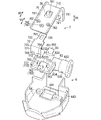
- FIG. 6 is an exploded perspective view of the upper end of the battery as seen from diagonally above.
- FIG. 7 is an exploded perspective view of the upper end of the battery as seen from diagonally below.
- FIG. 8 is a perspective view seen from diagonally below the frame from which the battery of the electric bicycle of the above is removed.
- FIG. 1 is a side view of an electric bicycle according to an embodiment.
- FIG. 2 is a side view of a main part of the same electric bicycle.
- FIG. 3 is a cross-sectional view taken along the line
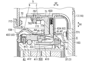
- FIG. 9 is a cross-sectional view of a portion of the electric bicycle including the holding device and the locking device of the same, in a locked state.
- FIG. 10 is a cross-sectional view showing a state in which the lock bar of the same portion is retracted.
- FIG. 11 is a cross-sectional view of a state in which the stopper in the same portion is retracted and the lock is released.
- FIG. 12 is a cross-sectional view of a state in which the same battery is being removed.
- FIG. 13 is an exploded perspective view of the battery of the modified example 1 and the holder supporting the battery as seen from diagonally above.
- FIG. 14 is a front view of the bottom cover included in the same battery.
- 15A is a sectional view taken along line dd of FIG. 14, and FIG.
- FIG. 15B is a sectional view taken along line ee of FIG.
- FIG. 16 is a side view of a main part of the same electric bicycle.
- FIG. 17 is a view taken along the line A of FIG.
- FIG. 18 is a cross-sectional view taken along the line bb of FIG.
- FIG. 19 is a perspective view of a main part of the same electric bicycle in a state where the battery is released from being fixed.
- FIG. 20 is a cross-sectional view taken along the line cc of FIG.
- FIG. 21 is a perspective view of the battery included in the electric bicycle of the same.
- FIG. 22 is an exploded perspective view of the upper end portion of the same battery.
- FIG. 23A is a top view with the cover member removed, showing when the operating lever is in the locked position in the holding device provided with the same battery
- FIG. 23B is a top view showing the operating lever in the unlocked position in the holding device of the same. It is a top view with the cover member removed, which shows the time when it is in.
- FIG. 24 is a side view of the same operating lever.
- FIG. 25 is a perspective view of the same battery combined with a lock unit.
- FIG. 26 is an exploded perspective view of the lock unit of the same.
- FIG. 27 is a cross-sectional view of a main part of the modified example 2 of the electric bicycle of the same as above.
- FIG. 28 is a cross-sectional view of a main part of the modified example 3 of the electric bicycle of the above.
- the electric bicycle 1 of the embodiment shown in FIG. 1 is an electrically assisted bicycle.
- the electric bicycle 1 of one embodiment includes a frame 10, two wheels 11 rotatably connected to the frame 10, a handle portion 12, a saddle portion 13, and a motor unit 15 attached to the frame 10.
- the two wheels 11 are a front wheel 111 and a rear wheel 112. Of these, the rear wheels 112 are rotationally driven by the driving force output from the motor unit 15.
- the vertical direction used in the text is defined based on the time when the electric bicycle 1 is placed on a horizontal plane.
- Each direction of front, back, left and right used in the text is defined with reference to the driver of the electric bicycle 1. That is, the direction in which the driver rides on the electric bicycle 1 is the front, the opposite side is the rear, the left direction when viewed from the driver is the left, and the right direction when viewed from the driver is the right. ..
- the frame 10 has a head tube 101, a top tube 102, a down tube 103, a seat tube 104, a seat stay 105, a chain stay 106, and a bracket 107.
- the frame 10 (that is, each of the above-mentioned parts constituting the frame 10) is made of a metal such as aluminum or stainless steel, but may contain a non-metal as a part.
- the entire frame 10 may be made of non-metal, and the material of the frame 10 is not particularly limited.
- the handle portion 12 is rotatably attached to the head tube 101.
- the front fork 121 extends downward from the lower end of the handle portion 12.
- a front wheel 111 is rotatably attached to the front fork 121.
- the front end of the top tube 102 is fixed to the head tube 101.
- the rear end of the top tube 102 is fixed to the seat tube 104.
- a saddle portion 13 is connected to the upper end of the seat tube 104.
- a bracket 107 is fixed to the lower end of the seat tube 104.
- the down tube 103 is a tube extending diagonally upward from the bracket 107, and the front end portion of the down tube 103 is fixed to the head tube 101.
- the down tube 103 is a tube extending diagonally downward from the head tube 101 toward the bracket 107, and the rear end portion of the down tube 103 is fixed to the bracket 107.
- the motor unit 15 is fixed to the lower side of the bracket 107.
- the front end of the chain stay 106 is fixed to the rear end of the bracket 107.
- the front end of the seat stay 105 is fixed to the rear end of the top tube 102.
- the rear end portion of the seat stay 105 is connected to the rear end portion of the chain stay 106, and the rear wheel 112 is rotatably mounted on the connecting portion.
- a crank arm 18 is rotatably inserted through the motor unit 15.
- a front sprocket 191 is provided inside the motor unit 15.
- a rear sprocket 192 is fixed to the hub of the rear wheel 112.
- a chain 193 is hung between the front sprocket 191 and the rear sprocket 192.
- the electric bicycle 1 of one embodiment includes a battery 2 for supplying electric power to the motor unit 15 and a lock unit 5 for attaching and detaching the battery 2 to the frame 10.
- the battery 2 includes a battery body 3 and a holding device 4 fixed to one end of the battery body 3 in the longitudinal direction.
- One end of the battery body 3 in the longitudinal direction is the upper end of the battery body 3.
- the lock unit 5 is composed of a lock device 6 to which the battery 2 is detachably mounted and a fixed structure 7 for fixing the lock device 6 to the frame 10.
- the lock device 6 detachably fixes a part of the battery 2 (that is, the holding device 4).
- the battery 2 is detachably fixed to the lock unit 5 including the lock device 6, and is detachably attached to the frame 10 via the lock unit 5.
- the lock unit 5 is attached to the down tube 103 of the frame 10.
- the down tube 103 is provided with a notch portion 108.
- the cutout portion 108 is diagonally forward and downward in the direction orthogonal to the longitudinal direction of the down tube 103 (first direction 91 shown in FIGS. 2, 9 and the like) (second direction 92 shown in FIGS. 2, 9 and the like). It is open toward.
- the battery 2 is attached to the down tube 103 via the lock unit 5 so as to fit into the notch portion 108.
- the battery body 3 constituting the main body of the battery 2 includes a plurality of storage battery cells 31, a tubular case 32 surrounding the plurality of storage battery cells 31, and a case 32.
- a cover portion 33 attached to the outer surface and a bottom cover 35 covering the lower end of the case 32 are provided.
- the cover portion 33 constitutes a part of the surface of the battery in a state of being attached to the outer surface of the case 32.
- the battery body 3 of one embodiment includes a plurality of storage battery cells 31, but at least one storage battery cell 31 may be provided.
- the longitudinal direction of the case 32 coincides with the longitudinal direction of the battery body 3 and also coincides with the longitudinal direction of the battery 2.
- Grooves 321 and 322 for hooking the cover portion 33 are formed on both left and right sides of the outer peripheral surface of the case 32 (see FIG. 3).
- the grooves 321 and 322 are bottomed grooves extending linearly in the longitudinal direction of the case 32, respectively, and are formed over the entire length of the case 32 in the longitudinal direction.
- the cover portion 33 has a cover member 330 having an arc-shaped cross section that constitutes the main body of the cover portion 33, and a cover holding member 331 having an arc-shaped cross section for mounting the cover member 330 on the case 32.
- a claw structure 332 for hooking the cover portion 33 to the case 32 is provided on the peripheral edge portion of the cover portion 33 (that is, the peripheral edge portion of the cover holding member 331).
- the claw structure 332 includes a left claw 333 and a right claw 334.
- the left claw 333 is caught in the groove 321 on the left side of the case 32, and the claw 334 on the right side is caught in the groove 322 on the right side of the case 32 so that the cover portion 33 covers a part of the outer peripheral surface of the case 32. It is temporarily fixed to the case 32. Further, the cover portion 33 is finally fixed to the holding device 4 and the bottom cover 35 by using a plurality of fixtures 36 (see FIG. 4).
- a rib structure 335 is provided on the peripheral edge of the cover portion 33 (that is, the peripheral edge of the cover holding member 331).
- the rib structure 335 has a left rib 336 protruding from the left edge portion of the cover portion 33 (that is, the left edge portion of the cover holding member 331) and a right edge portion of the cover portion 33 (that is, the cover holding member 331). Includes a right rib 337 protruding from the right edge).
- the left rib 336 and the right rib 337 are ribs extending in a straight line in the longitudinal direction of the cover portion 33, respectively.
- the longitudinal direction of the cover portion 33 coincides with the longitudinal direction of the case 32.
- the left rib 336 and the right rib 337 project in a direction away from each other in the left-right direction.
- the rib structure 335 further includes a left finger hook portion 338 extended from the upper end portion of the left rib 336 and a right finger hook portion 339 extended from the upper end portion of the right rib 337. Both the left finger hook 338 and the right finger hook 339 are composed of L-shaped ribs that are extended in a direction approaching each other and bent upward in the middle.
- a holder 109 for detachably holding the lower end portion of the battery 2 is provided at the lower end portion of the notched portion 108 of the frame 10.
- the cover portion 33 forming a part of the outer surface of the battery 2 is exposed to the outside.
- a gap 200 is formed between the peripheral edge portion of the cover portion 33 (that is, the peripheral edge portion of the cover holding member 331) and the notched portion 108 of the frame 10.
- the gap 200 is a gap for suppressing the user's finger from being caught between the battery 2 and the notched portion 108.
- the gap 200 is preferably 8 mm or more.
- the gap 200 includes a left gap 201 formed along the left edge of the battery 2 and a right gap 202 formed along the right edge of the battery 2.
- the gap 201 on the left side and the gap 202 on the right side are each formed in a straight line in the longitudinal direction of the battery 2.
- the longitudinal direction of the battery 2 coincides with the longitudinal direction of the notch 108, and the longitudinal direction of the portion of the frame 10 to which the battery 2 is attached is long. It coincides with the direction (specifically, the longitudinal direction of the down tube 103 (first direction 91 shown in FIGS. 2, 9, etc.)).
- the rib structure 335 of the battery body 3 is located in front of the gap 200 in a state where the battery 2 is attached to the cutout portion 108 of the frame 10.
- the left rib 336 included in the rib structure 335 is located in front of the left gap 201
- the right rib 337 included in the rib structure 335 is located in front of the right gap 202. Therefore, even if mud or the like scatters from the front toward the gap 200, it hits the rib structure 335 and is stopped. Therefore, it is possible to prevent mud and the like from entering the gap 200.
- the presence of the left rib 336 and the right rib 337 allows the user to put his or her finger on the left rib 336 and the right rib 337, respectively, to stably grip the battery 2.
- the tips of the left rib 336 and the right rib 337 are preferably smoothly rounded.
- the holding device 4 constituting the upper end portion of the battery 2 will be described with reference to FIGS. 4 to 7 and the like.
- the holding device 4 is used to detachably hold the battery body 3 with respect to the lock device 6 fixed to the frame 10 of the electric bicycle 1.
- the holding device 4 is fixed to the upper end of the case 32 included in the battery body 3 by using a plurality of fixtures 49 (see FIG. 6).
- Each fixative 49 is, for example, a screw.
- the upper end opening of the case 32 having a bottomless cylinder is closed by the holding device 4, and the lower end opening of the case 32 is closed by the bottom cover 35.
- the holding device 4 includes a base portion 41 fixed to the case 32 so as to close the upper end opening of the case 32, a stopper member 420 formed with a stopper 42 which is a first lock portion and a second lock portion, and a base portion.
- the operation lever 43 that is movable with respect to the 41 and moves the stopper 42, the elastic member 44 that gives urging force to the stopper member 420 and the operation lever 43, and at least a part of the operation lever 43 and the elastic member 44 are covered.
- a cover member 45 fixed to the base portion 41 is provided.
- the stopper 42 is configured so that a part of the locking device 6 can be selectively locked.
- a part of the locking device 6 is a locking portion 61 (that is, a lock bar 634, see FIGS. 8 and 9), which will be described later.
- the locking portion 61 will be described as the first locking portion 61 in the following description.
- the base portion 41 is a base member molded using resin, and includes a flat plate-shaped main body 411 that closes the upper end opening of the case 32 and a peripheral wall portion 412 that protrudes upward from the main body 411. Integrally. A region 410 for rotatably arranging the operation lever 43 is provided on the surface (that is, the upper surface) of the main body 411 opposite to the facing surface 414 facing the battery main body 3.
- the peripheral wall portion 412 is formed with a notch portion 413 for rotatably inserting a part of the operating lever 43. A part of the operation lever 43 inserted into the notch portion 413 is a support shaft portion 431 which will be described later.
- the peripheral wall portion 412 protrudes from the portion of the main body 411 surrounding the area 410 toward the direction away from the battery main body 3 (that is, upward).
- the stopper member 420, the operation lever 43, and the cover member 45 are rotatably arranged in the space surrounded by the main body 411 and the peripheral wall portion 412.
- the region 410 of the main body 411 and the peripheral wall portion 412 surrounding the region 410 form an accommodating recess for accommodating the stopper member 420, the operating lever 43, and the cover member 45.
- the accommodating recess is open toward the distance from the battery body 3.
- the stopper member 420 is integrally provided with the stopper 42.
- the stopper 42 is configured so that the first locking portion 61 of the locking device 6 is locked.
- the stopper 42 projects in a direction orthogonal to the facing surface 414 toward a direction away from the main body 411.
- the operation lever 43 is movable between a locking position where the stopper 42 is locked to the first locking portion 61 and a non-locking position where the stopper 42 is not locked to the first locking portion 61.
- the operating lever 43 is formed at the lever main body 430, the columnar support shaft portion 431 projecting toward the base portion 41 on one end side of the lever main body 430, and the end portion of the lever main body 430 opposite to the support shaft portion 431.
- the pushed-in portion 433 and the acting portion 432 formed between the support shaft portion 431 and the pushed-in portion 433 are integrally provided.
- the support shaft portion 431 is rotatably connected to the main body 411 by being inserted into the cutout portion 413 of the base portion 41.
- the pushing portion 433 of the operating lever 43 is movable in a direction orthogonal to the facing surface 414 of the base portion 41 (first direction 91 in FIG. 9).
- the distance between the support shaft portion 431 and the push-in portion 433 is larger than the distance between the support shaft portion 431 and the action portion 432. Therefore, in the holding device 4 of one embodiment, there is an advantage that it is easy to secure the moving width of the pushing portion 433 and it is easy to apply a large force to the acting portion 432.
- the operation lever 43 is swingable around the axis of the support shaft portion 431 with the support shaft portion 431 as the center.
- the elastic member 44 is a coil-shaped spring provided separately from the operating lever 43.
- the elastic member 44 is arranged between the main body 411 and the stopper member 420 so as to maintain a compressed state.
- the elastic member 44 is provided so as to always apply an urging force to the stopper member 420 and the operating lever 43.
- the urging force applied to the stopper member 420 and the operating lever 43 is an urging force in a direction orthogonal to the facing surface 414 of the base portion 41 (first direction 91 in FIG. 9).
- the stopper member 420 and the operation lever 43 are urged by the elastic member 44 to hold the locking position shown in FIG. 9 when an external force due to the pushing operation of the user does not work.
- the cover member 45 is detachably fixed to the main body 411 of the base portion 41 by using, for example, a fixing tool made of screws. By removing the fixture from the base portion 41 and removing the cover member 45 from the base portion 41, at least one of the stopper member 420 and the operating lever 43 can be replaced. It is also possible to remove the cover member 45 once and replace the elastic member 44.
- the cover member 45 is fixed to the base portion 41 so as to close the opening above the accommodating recess (region 410) and cover a part of the operating lever 43, the stopper member 420, and the elastic member 44.
- the locking device 6 is a device constituting the main body of the lock unit 5 fixed to the frame 10, and as shown in FIG. 9 and the like, the holding device 4 forming a part of the battery 2 is detachably fixed. can do.
- the holding device 4 and the locking device 6 form a battery holding mechanism 8 for holding the battery 2 in the frame 10.
- the lock device 6 includes a main lock portion 63 that can be operated using a key, and a lock holder 64 that is integrally combined with the main lock portion 63.
- the lock holder 64 also has an effect of protecting the battery 2 from directly hitting a place other than the cutout portion 108 of the frame 10 when the battery 2 is attached to the frame 10. That is, the lock holder 64 protects the frame 10.
- the main lock portion 63 is composed of a cylinder lock and has a cylinder (not shown), a lock case 633, and a keyhole 631 (see FIG. 2 and the like).
- the cylinder is configured so that its inner cylinder portion rotates by inserting a predetermined key into a keyhole 631 provided on one end surface thereof and turning it.
- the lock device 6 is configured such that the tip end portion of the lock bar 634 protrudes from the lock case 633 as the inner cylinder portion of the cylinder rotates.
- the lock bar 634 movably held by the main lock portion 63 constitutes the first locking portion 61 to be locked to the stopper 42 of the holding device 4. That is, with the tip portion of the lock bar 634 protruding downward, the tip portion of the lock bar 634 is locked to the stopper 42, so that the battery 2 is fixed so as not to come off from the cutout portion 108 of the frame 10. To.
- the lock bar 634 is retracted by operating the main lock portion 63, the lock bar 634 maintains the lock with the stopper 42. As a result, the main lock of the battery 2 with respect to the frame 10 is released.
- the tip portion of the lock bar 634 in the locked position is locked to the stopper 42 of the stopper member 420, whereby the battery 2 cuts the frame 10. It is fixed so as not to come off from the notch portion 108.
- the fixed structure 7 is a structure that constitutes the lock unit 5 in combination with the lock device 6, and the lock device 6 is connected to the longitudinal end portion (specifically, the notch) of the notch portion 108 of the frame 10. It has a function of fixing to the upper end portion of the portion 108).
- the longitudinal direction of the notched portion 108 coincides with the longitudinal direction of the portion of the frame 10 to which the battery 2 is mounted (that is, the down tube 103).
- the fixed structure 7 is a first structure for fixing the first sheet metal 71 constituting the main part of the fixed structure 7, the second sheet metal 72 assisting the first sheet metal 71, and the first sheet metal 71 to the frame 10. And a second structure for fixing the first sheet metal 71 to the lock device 6.
- the second sheet metal 72 is a sheet metal smaller than the first sheet metal 71.
- the structure for fixing the first sheet metal 71 and the frame 10 includes at least one hole provided in the first sheet metal 71 and at least one fixing tool 771 inserted into the hole.
- the fixture 771 is, for example, a screw, which is inserted into a hole formed in the first sheet metal 71 and fixed to the frame 10.
- the structure for fixing the first sheet metal 71 and the locking device 6 is formed in at least one hole 762 provided in the first sheet metal 71, at least one fixing tool 772 inserted into the hole 762, and a lock case 633 of the locking device 6. Includes at least one hole 763 provided.
- at least one hole 762 is a plurality of holes 762 (specifically, three holes 762)
- at least one fixing tool 772 is a plurality of fixing tools 772 (specifically, three holes 762). Is a fixture 772)
- at least one hole 763 is a plurality of holes 763 (specifically, three holes 763).
- Each hole 762 of the first sheet metal 71 is a screw hole that penetrates.
- Each fixative 772 is, for example, a screw, inserted into the corresponding hole 763, and fixed to the first sheet metal 71 in a state of being inserted into the corresponding hole 762. As a result, the first sheet metal 71 and the lock device 6 are fixed.
- the structure for fixing the second sheet metal 72 and the frame 10 includes at least one hole provided in the second sheet metal 72 and at least one fixing tool 773 to be inserted into the hole.
- the fixture 773 is, for example, a screw, which is inserted into a hole formed in the second sheet metal 72 and fixed to the frame 10.
- the structure for fixing the second sheet metal 72, the first sheet metal 71, and the locking device 6 includes at least one hole provided in the second sheet metal 72, at least one fixing tool 774 inserted into the hole, and a locking device. It includes at least one hole provided in the lock case 633 of No. 6 and at least one hole provided in the first sheet metal 71.
- at least one hole is one hole
- at least one fixture 774 is one fixture 774
- at least one hole is one hole, at least.
- One hole is one hole.
- Fixture 774 is, for example, a screw.
- the fixative 774 is inserted into the hole provided in the corresponding first sheet metal 71 through the hole provided in the second sheet metal 72.
- the second sheet metal 72 is fixed to the first sheet metal 71 and is fixed to the lock device 6.
- the first state is the state in which the movement with respect to the lock device 6 is restricted by the first lock portion and the second lock portion.
- the first unlocking operation is an operation of inserting a key into the keyhole 631 and turning it in a predetermined direction to retract the lock bar 634 (first locking portion 61) upward as shown in FIG.
- the first unlock operation is completed and the second state is reached. That is, the second state is a state in which the restriction by the first lock portion is released and the movement of the lock device 6 is restricted by the second lock portion.
- the second lock portion regulates the movement of the lock device 6, so that the first lock portion 61 is still on the stopper 42. It is in a locked state, and the lock of the battery 2 to the frame 10 is not released.
- the relative positions of the locking device 6 and the holding device 4 do not change between the first state and the second state.
- the second unlocking operation is an operation in which the user grasps the upper end portion of the battery 2 with, for example, the left hand, and pushes the pushing portion 433 downward (in the direction along the first direction 91) with the thumb of the left hand as it is.
- the user grasps the upper end portion of the battery 2 with his right hand and pushes the pushing portion 433 downward with the index finger of his right hand as it is.
- the pushing portion 433 is pushed in, as shown in FIG. 11, the stopper member 420 is pushed downward by the operating lever 43 in the holding device 4, the stopper 42 moves downward, and the first locking is performed. The locking between the portion 61 and the stopper 42 is released, and the second unlocking operation is completed.
- the user can safely and easily remove the battery 2 while holding the battery 2.
- the lower end portion of the battery 2 is first placed on the lower end portion of the notch portion 108 (that is, the holder 109), and the battery 2 is rotated backward around the lower end portion of the notch portion 108. ..
- the stopper 42 retreats downward once against the urging force at the position where it hits the first locking portion 61, and then returns to the original position (locking position) by the urging force (see FIG. 10). As a result, the first locking portion 61 is locked to the stopper 42.
- the user inserts the key into the keyhole 631 and turns it in the direction opposite to the predetermined direction to move the lock bar 634 further downward, thereby locking the lock bar 634 to the stopper 42 of the holding device 4. , Locked.
- the battery 2 can be fixed to the frame 10 of the electric bicycle 1 in two stages to improve safety.
- the user can safely and easily perform the work of removing the battery 2 from the frame 10 and the work of attaching the battery 2 to the frame 10.
- the frame 10 can be designed so that the distance between the down tube 103 and the front wheel 111 can be shortened, for example. The degree of freedom is increased.
- the holding device 4 of the modification 1 is a holding device 4 used for holding the battery body 3 detachably with respect to the lock device 6 fixed to the frame 10 of the electric bicycle 1, and this point is described above. It is the same as the embodiment.
- the holding device 4 of the modification 1 includes a locking member (operating lever 43) in the locking device 6 at a point where the stopper 42 is configured to be locked to the first locking portion 61 included in the locking device 6. It differs from the above-described embodiment in that it is configured to be locked to the second locking portion 62.
- the first locking portion 61 is movable in the first direction 91. At least one of the second locking portion 62 and the locking member is at a locking position where the second locking portion 62 and the locking member are locked to each other, and the second locking portion 62 and the locking member are not locked to each other. It can move to and from the unlocked position in a second direction 92, which is different from the first direction 91.
- a notch 34 is provided in the upper edge portion of the cover portion 33 (that is, the upper edge portion of the cover holding member 331).
- the notch 34 is a notch for projecting the pushing portion 433 of the operating lever 43 as a locking member to the outside, and has a shape recessed downward.
- the notch 34 is located above one of the left and right finger hooks 338 and 339, and in the battery 2 is above the left finger hook 338.
- the bottom cover 35 constituting the lower end of the battery body 3 has a notch portion both when the battery 2 is attached to the notch portion 108 of the frame 10 and when the battery 2 is removed from the notch portion 108 of the frame 10. It is configured to be in sliding contact with the lower end portion of 108.
- concave curved surfaces 350 that smoothly guide the rotation of the battery 2 when it is attached and detached are provided at two locations separated from each other to the left and right.
- the concave curved surface 350 is a concave curved surface recessed in a spherical shape with reference to the rotation center point when the battery 2 is attached / detached.
- a protruding portion 352 that protrudes forward from the concave curved surface 350 is provided between the left and right concave curved surfaces 350 (see FIG. 15B).
- the holder 109 is provided with a convex curved surface 100 configured to hit the concave curved surface 350 at the lower end of the battery 2.
- the convex curved surface 100 is a convex curved surface that protrudes spherically with respect to the rotation center point when the battery 2 is attached / detached.
- the concave curved surface 350 of the battery 2 is in sliding contact with the convex curved surface 100 of the holder 109, so that stable rotation of the battery 2 is realized.
- the gap 200 in the first modification is a gap for suppressing foreign matter or a user's finger from being caught between the battery 2 and the notched portion 108.
- the gap 200 is preferably a gap that causes a distance of 8 mm or more between the battery 2 and the frame 10.
- the distance here is the distance between the outermost part (that is, the most raised part) of the rib structure 335 (raised structure) and the outermost part of the cutout portion 108 of the frame 10. Is.
- the gap 201 on the left side is preferably a gap that allows a distance of 8 mm or more between the left end edge of the battery 2 and the notched portion 108 of the frame 10.
- the distance here is between the outermost part of the left rib 336 (left raised part) (that is, the most raised part) and the outermost part of the cutout portion 108 of the frame 10. The distance.
- the gap 202 on the right side is preferably a gap that allows a distance of 8 mm or more between the right end edge of the battery 2 and the notched portion 108 of the frame 10.
- the distance here is between the outermost part of the right rib 337 (right raised part) (that is, the most raised part) and the outermost part of the cutout portion 108 of the frame 10. The distance.
- the base portion 41 in the modified example 1 integrally has a main body 411, a peripheral wall portion 412, and a protruding portion 4131 protruding from the main body 411 in the same direction as the peripheral wall portion 412.
- the peripheral wall portion 412 protrudes from the portion of the main body 411 surrounding the area 410 toward the direction away from the battery main body 3 (that is, upward).
- the operation lever 43 is rotatably arranged in the space surrounded by the main body 411 and the peripheral wall portion 412.
- the region 410 of the main body 411 and the peripheral wall portion 412 surrounding the region 410 form an accommodating recess 415 accommodating the operating lever 43.
- the accommodating recess 415 is opened in a direction away from the battery body 3.
- the peripheral wall portion 412 is provided with an opening 418 for projecting a part of the operating lever 43 to the outside.
- a part of the operating lever 43 protruding from the opening 418 is a portion including an acting portion 432 as a locking portion and a pushing portion 433.
- the first portion of the opening 418 that projects the working portion 432 outward and the second portion that projects the pushing portion 433 outward are provided in one connection, but the opening 418 is provided.
- the first portion and the second portion of the above may be provided discontinuously.
- a metal lock plate 46 is detachably fixed to the protrusion 4131 using a fixture 48.
- the lock plate 46 is a reinforcing plate obtained by bending a metal plate material such as stainless steel, and the stopper 42 is configured by fixing the lock plate 46 to the resin protrusion 4131. With the lock plate 46 fixed to the protrusion 4131, the surface of the lock plate 46 constitutes the surface of the stopper 42.
- the operating lever 43 includes a lever main body 430, a columnar support shaft portion 431 protruding from the lever main body 430 toward the base portion 41, an action portion 432 protruding from the lever main body 430 to one side in the left-right direction, and a lever main body. It integrally has a push-in portion 433 that protrudes from the 430 to one side in the left-right direction.
- the support shaft portion 431 is rotatably connected to the main body 411 by being inserted into the hole of the base portion 41.
- the acting unit 432 is configured to be selectively locked to a part of the locking device 6.
- a part of the locking device 6 here is a second locking portion 62 (recessed portion 645) (see FIG. 20).
- the pushing portion 433 is a portion for the user to push with a finger, and is configured so that the user's finger touches the tip surface thereof.
- the acting portion 432 and the pushing portion 433 project from different portions of the lever main body 430 toward the same side.
- both the acting portion 432 and the pushing portion 433 project to the left.
- the amount of protrusion of the pushing portion 433 from the lever main body 430 is larger than the amount of protrusion of the acting portion 432 from the lever main body 430.
- the amount of protrusion of the pushing portion 433 from the lever main body 430 is more than twice the amount of protrusion of the working portion 432 from the lever main body 430, and more than three times the amount of protrusion of the acting portion 432 from the lever main body 430. Is preferable.
- the holding device 4 of the modified example 1 has an advantage that it is easy to secure the moving width of the pushing portion 433 and it is easy to apply a large force to the acting portion 432.
- the amount of protrusion of the support shaft portion 431 from the lever main body 430 is larger than the amount of protrusion of the push-in portion 433 from the lever main body 430 (see FIG. 24).
- the support shaft portion 431 has a larger dimension than the other parts of the operating lever 43 (that is, each of the lever body 430, the action portion 432, and the push-in portion 433). It is preferable in terms of ensuring the strength of the portion 431.
- the action portion 432 projects to the side (that is, upper side) opposite to the side on which the support shaft portion 431 projects with respect to the lever body 430.
- the operation lever 43 can swing in the left-right direction around the support shaft portion 431 between the locked position shown in FIG. 23A and the non-locked position shown in FIG. 23B.
- the acting portion 432 projects outward through the opening 418 of the peripheral wall portion 412.
- the acting portion 432 protruding outward can be locked to the second locking portion 62 of the locking device 6.
- the acting portion 432 does not project outward through the opening 418.
- the acting portion 432 cannot be locked to the second locking portion 62 of the locking device 6.
- the elastic member 44 is a coil-shaped spring provided separately from the operation lever 43.
- the elastic member 44 is arranged between the peripheral wall portion 412 and the operating lever 43 so as to maintain a compressed state.
- the elastic member 44 is provided so as to always apply an urging force to the operating lever 43.
- the urging force applied to the operating lever 43 is a urging force in a direction parallel to the base portion 41 (that is, a direction parallel to the flat plate-shaped main body 411).
- the operating lever 43 is urged by the elastic member 44 to hold the locking position shown in FIG. 23A when an external force due to the pushing operation of the user does not act.
- the cover member 45 is detachably fixed to the main body 411 of the base portion 41 by using the fixing tool 48.
- the fixture 48 is a fixture that collectively fixes the cover member 45 and the lock plate 46 to the base portion 41.
- the fixative 48 is, for example, a screw.
- the cover member 45 is fixed to the base portion 41 so as to close the upper opening of the accommodating recess 415 and cover a part of the operating lever 43 and the elastic member 44.
- a part of the operating lever 43 here is a portion of the operating lever 43 excluding the working portion 432 and the pushing portion 433.
- the cover member 45 is provided with a notch 451 for allowing the working portion 432 to move in the left-right direction.
- the working portion 432 can swing in the left-right direction within the range of the notch 451.
- the operation lever 43 is restricted from moving to one side (that is, the right side) in the left-right direction by the action portion 432 hitting the notch 451. Further, the operation lever 43 is restricted from moving to the other side (that is, the left side) in the left-right direction by a part of the operation lever 43 hitting the peripheral wall portion 412.
- the cover member 45 may cover at least a part of the operation lever 43, and may cover the entire operation lever 43, for example.
- the cover member 45 may be fixed to the base portion 41 so as to cover at least the portion of the operating lever 43 excluding the pushing portion 433, or may cover the portion of the operating lever 43 excluding at least the acting portion 432. It may be fixed to the base portion 41.
- the lock device 6 is a device that constitutes the main body of the lock unit 5 that is fixed to the frame 10, and as shown in FIG. 18 and the like, the holding device 4 that constitutes a part of the battery 2 is detachably fixed. Can be done.
- the holding device 4 and the locking device 6 form a battery holding mechanism 8 for holding the battery 2 in the frame 10.
- the lock device 6 includes a main lock portion 63 that can be operated by using a key, and a lock holder 64 that is integrally combined with the main lock portion 63.
- the main lock portion 63 is composed of a cylinder lock.
- the main lock portion 63 includes a cylindrical cylinder 632 having a keyhole 631 (see FIG. 2 and the like), a lock case 633 integrally combined with the cylinder 632, and a lock bar 634 housed in the lock case 633.
- the lock case 633 integrally has a square tubular first portion 6331 in which the lock bar 634 is movably accommodated and a second portion 6332 for connecting to the fixed structure 7.
- the moving direction of the lock bar 634 is the same as that of the first direction 91.
- the amount that the lock bar 634 can move in this direction is preferably set within the range of 6 mm to 10 mm, for example, 8 mm.
- the amount that the lock bar 634 can move in the first direction 91 is set to be larger than the amount that the lock device 6 can adjust the position with respect to the frame 10 in the first direction 91 (in other words, the first direction 91).
- the amount that the lock device 6 can adjust the position with respect to the frame 10 is set to be smaller than the amount that the lock bar 634 can move in the first direction 91).
- the cylinder 632 is configured so that its inner cylinder portion rotates by inserting a predetermined key into a keyhole 631 provided on one end surface thereof and turning it.
- the lock device 6 is configured so that the amount of the tip portion of the lock bar 634 protruding from the first portion 6331 of the lock case 633 is switched as the inner cylinder portion of the cylinder 632 rotates.
- the lock bar 634 movably held by the main lock portion 63 constitutes the first locking portion 61 to be locked to the stopper 42 of the holding device 4. That is, in a state where the tip portion of the lock bar 634 is projected downward from the first portion 6331, the tip portion of the lock bar 634 is locked to the stopper 42 (see FIG. 18), so that the battery 2 cuts the frame 10. It is fixed so as not to come off from the notch portion 108.
- the lock bar 634 is immersed in the first portion 6331 by operating the main lock portion 63, the lock bar 634 moves to a position where it is not locked to the stopper 42. As a result, the main lock of the battery 2 with respect to the frame 10 is released.
- the lock holder 64 has a rectangular through hole 641 into which the convex first portion 6331 included in the lock case 633 is fitted, and a positioning piece 643 into which a part of the main lock portion 63 is fitted. With the first portion 6331 fitted in the through hole 641, the lock bar 634 can project toward the holding device 4 through the opening of the first portion 6331.
- a part of the main lock portion 63 is provided with an arc-shaped notch 638 for fitting the positioning piece 643.
- the tip edge of the positioning piece 643 has a concave shape in an arc shape so as to match the notch 638.
- a part of the lock holder 64 is provided so as to cover the upper end portion of the notch portion 108 from the outside in a state where the lock device 6 is fixed to the frame 10.
- a part of the lock holder 64 here is a portion of the lock holder 64 provided so as to project upward from the outermost portion of the lock holder 64 when the lock device 6 is fixed to the frame 10. be.
- the lower surface 640 of the lock holder 64 (that is, the surface facing the holding device 4) is formed with a recess 645 to which the acting portion 432 of the operating lever 43 can be locked. ..
- the recess 645 of the lock holder 64 constitutes the second locking portion 62 to which the operation lever 43 is locked.
- the acting portion 432 of the operating lever 43 in the locked position is locked in the recess 645, whereby the battery 2 is moved from the notched portion 108 of the frame 10. It is fixed so that it will not come off.
- the acting portion 432 of the operating lever 43 moves to a position where it is not locked to the recess 645. As a result, the subblock of the battery 2 with respect to the frame 10 is released.
- the battery 2 is doubly fixed to the frame 10 by the main lock by the key operation and the sublock using the operation lever 43.
- the relative positions of the first locking portion 61 and the second locking portion 62 of the locking device 6 are determined with high accuracy.
- the main locking portion 63 that movably holds the first locking portion 61 that is, the lock bar 634
- the second locking portion 62 that is, the recess 645 of the lock holder 64
- the relative positions of the first locking portion 61 and the second locking portion 62 are determined with high accuracy.
- the fixed structure 7 is a structure that constitutes the lock unit 5 in combination with the lock device 6, and the lock device 6 is connected to the longitudinal end portion (specifically, the notch portion 108) of the notch portion 108 of the frame 10. Has the function of fixing to the upper end of the).
- the longitudinal direction of the notched portion 108 coincides with the longitudinal direction of the portion of the frame 10 to which the battery 2 is mounted (that is, the down tube 103).
- the fixed structure 7 is a structure that is fixed to the frame 10 in an adjustable position and is fixed to the lock device 6 in an adjustable position.
- the fixed structure 7 and the frame 10 are fixed in a predetermined range in the first direction 91, and the fixed structure 7 and the locking device 6 are fixed in a predetermined range in the second direction 92.
- the second direction 92 is a direction different from that of the first direction 91. It is preferable that the first direction 91 and the second direction 92 are orthogonal to each other.
- the dimensions of the fixed structure 7 are adjustable in the third direction 93. Since the dimensions of the fixed structure 7 can be adjusted, even if the dimensions of the frame 10 vary in the manufacturing stage, the variation can be absorbed by the dimensional adjustment of the fixed structure 7.
- the third direction 93 is a direction different from the first direction 91. It is preferable that the first direction 91 and the third direction 93 are orthogonal to each other.
- the first direction 91 is the longitudinal direction of the notch portion 108, the longitudinal direction of the portion of the frame 10 to which the battery 2 is mounted (that is, the down tube 103), and also. This is the longitudinal direction of the battery 2 when the battery 2 is mounted on the frame 10.
- the second direction 92 is the width direction in front of and behind the down tube 103, and is orthogonal to the first direction 91.
- the third direction 93 is the width direction in front of and behind the down tube 103 like the second direction 92, and is orthogonal to the first direction 91. It is also possible to paraphrase the first direction 91 as the vertical direction and the second direction 92 and the third direction 93 as the front-back direction.
- the fixing structure 7 is for fixing the first sheet metal 71 constituting the main part of the fixing structure 7, the second sheet metal 72 assisting the first sheet metal 71, and the first sheet metal 71 to the frame 10 so as to be adjustable in position.
- the first structure and the second structure for fixing the first sheet metal 71 to the lock device 6 so as to be adjustable in position are included.
- the second sheet metal 72 is a sheet metal smaller than the first sheet metal 71.
- the first sheet metal 71 is an L-shaped sheet metal having a corner portion 715.
- the portion 711 on the first side sandwiching the corner portion 715 is a flat plate-shaped portion fixed in an adjustable position with respect to the frame 10.
- the second side portion 712 sandwiching the corner portion 715 of the first sheet metal 71 is a flat plate-shaped portion fixed to the lock device 6 so as to be adjustable in position.
- the corner portion 715 is curved in an arc shape so as to smoothly connect the first side portion 711 and the second side portion 712.
- the first structure for fixing the first sheet metal 71 and the frame 10 includes at least one hole 761 provided in the first side portion 711 of the first sheet metal 71, and at least one fixing tool 771 inserted therein. including.
- At least one hole 761 is a plurality of holes 761 (specifically, two holes 761), and at least one fixing tool 771 is a plurality of fixing tools 771 (specifically, two holes 761).
- Each hole 761 is an elongated hole penetrating with the first direction 91 as the longitudinal direction.
- Each fixture 771 is, for example, a screw that is inserted through the corresponding hole 761 and fixed to the frame 10. With the fixture 771 inserted through the corresponding hole 761, the first sheet metal 71 and the frame 10 are within a range in which each fixative 771 can move in the first direction 91 with respect to the corresponding hole 761. The position is adjustable and fixed in the first direction 91.
- the second structure for fixing the first sheet metal 71 and the locking device 6 is inserted into at least one hole 762 provided in the second side portion 712 of the first sheet metal 71. It includes at least one fixative 772 and at least one hole 763 provided in the lock case 633 of the locking device 6.
- at least one hole 762 is a plurality of holes 762 (specifically, three holes 762)
- at least one fixing tool 772 is a plurality of fixing tools 772 (specifically, three holes 762). Is a fixture 772)
- at least one hole 763 is a plurality of holes 763 (specifically, three holes 763).
- Each hole 762 of the second side portion 712 is a threaded hole.
- Each hole 763 of the lock case 633 is an elongated hole penetrating with the second direction 92 as the longitudinal direction.
- Each fixative 772 is, for example, a screw, inserted into the corresponding hole 763, and fixed to the first sheet metal 71 in a state of being inserted into the corresponding hole 762. As a result, the first sheet metal 71 and the lock device 6 are fixed. The position of the first sheet metal 71 and the locking device 6 can be adjusted in the second direction 92 within a range in which each fixture 772 can be moved in the second direction 92 while being inserted into the corresponding hole 763.
- the second sheet metal 72 is an L-shaped sheet metal having a corner portion 725.
- the first side portion 721 sandwiching the corner portion 725 is a flat plate-shaped portion fixed in an adjustable position with respect to the frame 10.
- the second side portion 722 sandwiching the corner portion 725 of the second sheet metal 72 is a flat plate-shaped portion fixed to the first sheet metal 71 and the lock device 6 so as to be adjustable in position.
- the structure for fixing the second sheet metal 72 and the frame 10 includes at least one hole 764 provided in the first side portion 721 of the second sheet metal 72, and at least one fixing tool 773 inserted therein.
- At least one hole 764 is a plurality of holes 764 (specifically, two holes 764), and at least one fixing tool 773 is a plurality of fixing tools 773 (specifically, two holes 764).
- Each fixative 773 is, for example, a screw.
- Each hole 764 is a screw hole into which the fixative 771 is inserted.
- Each fixative 773 is inserted into the corresponding hole 764 through an elongated hole formed in the frame 10 such that the first direction 91 is the longitudinal direction.
- the second sheet metal 72 and the frame 10 are fixed in the first direction 91 so as to be adjustable in position.
- the structure for fixing the second sheet metal 72, the first sheet metal 71, and the locking device 6 includes at least one hole 765 provided in the second side portion 722 of the second sheet metal 72, and at least one inserted into the hole 765. It includes one fixative 774, at least one hole 766 provided in the lock case 633 of the locking device 6, and at least one hole 767 provided in the second side portion 712 of the first sheet metal 71.
- at least one hole 765 is one hole 765
- at least one fixture 774 is one fixture 774
- at least one hole 766 is one hole 766.
- at least one hole 767 is one hole 767.
- Fixture 774 is, for example, a screw.
- the hole 765 of the second sheet metal 72 is a long hole that penetrates with the third direction 93 as the longitudinal direction.
- the fixative 774 for fixing the second sheet metal 72 and the locking device 6 is composed of one of three fixing tools 772 for fixing the first sheet metal 71 and the locking device 6.
- the hole 766 of the lock case 633 is composed of one of three holes 763 for fixing the first sheet metal 71 and the lock device 6.
- the hole 767 of the first sheet metal 71 is a through-threaded screw hole, and is composed of one of three holes 762 for fixing the first sheet metal 71 and the locking device 6.
- Fixture 774 is inserted into the corresponding hole 767 through the hole 765 with the third direction 93 as the longitudinal direction.
- the second sheet metal 72 is fixed to the first sheet metal 71 so as to be position-adjustably fixed in the third direction 93, and is fixed to the lock device 6 so as to be position-adjustably fixed to the lock device 6.
- the second portion 6332 of the lock case 633 provided with the lock device 6 is provided with a recess 6335 for fitting a part 728 of the second sheet metal 72.
- the part 728 of the second sheet metal 72 is a part of the part 722 on the second side, and more specifically, the part of the part 722 on the second side provided with the hole 765.
- a part 728 of the second sheet metal 72 is movable within a predetermined range in the third direction 93 while being fitted in the recess 6335. By fitting a part 728 of the second sheet metal 72 into the recess 6335, the relative positioning work between the second sheet metal 72 and the locking device 6 can be easily performed.
- the second sheet metal 72 and the locking device 6 are collectively fixed to the first sheet metal 71 by using the common fixing tool 774 (772).
- the third direction 93 is preferably the same as the second direction 92.
- the hook 65 protrudes from the lock case 633 toward the first sheet metal 71 (that is, upward).
- the hook 65 has a first portion 651 extending from the lock case 633 in the first direction 91, and a second portion 652 extending in the second direction 92 from a part (specifically, the tip portion) of the first portion 651.
- the second portion 652 extends to the rear side in the second direction.
- the insertion hole 78 is a rectangular hole that penetrates the second side portion 712 of the first sheet metal 71.
- the hook 65 is in a state where the first portion 651 is inserted into the insertion hole 78 and the second portion 652 hits the second side portion 712 of the first sheet metal 71. It is slidably locked to the first sheet metal 71. As a result, when the load of the battery 2 is applied to the lock unit 5, the lock unit 5 is prevented from being deformed due to the load.
- the battery 2 is attached to the frame 10 by using both the main lock function based on the user's key operation and the sublock function using the operation lever 43.
- the key is first inserted into the keyhole 631 and turned in a predetermined direction, and the lock bar 634 is pulled up and immersed in the lock device 6 to hold the lock bar 634.
- the main lock can be released by separating it from the stopper 42 of 4.
- the acting portion 432 of the holding device 4 is locked to the locking device 6, and the sublock is maintained.
- the user can grasp the upper end portion of the battery 2 with, for example, the left hand, and push the push-in portion 433 horizontally with the thumb of the left hand as it is.
- the user can grasp the upper end portion of the battery 2 with his right hand and push the push-in portion 433 in the horizontal direction with the index finger of his right hand as it is.
- the pushing portion 433 is pushed in, the operating lever 43 operates in the holding device 4, and the sublock by the acting portion 432 is released. The user can safely and easily remove the battery 2 while holding the battery 2.
- the user inserts the key into the keyhole 631 and turns it in the direction opposite to the predetermined direction to lower the lock bar 634 and project it from the lock device 6, thereby causing the lock bar 634 to be a stopper 42 of the holding device 4. It can be locked and the main lock can be applied.
- the battery 2 can be double-fixed to the frame 10 of the electric bicycle 1 to enhance safety.
- the user can safely and easily perform the work of removing the battery 2 from the frame 10 and the work of attaching the battery 2 to the frame 10.
- the battery 2 is maintained in a state of being fitted in the notch portion 108 until the sublock is released, and the lock device 6 is used. And the relative position of the holding device 4 do not change.
- the wording that the relative position does not change here includes the case where there is a design-acceptable rattling.
- the rattling is preferably, for example, rattling within 0.6 mm, and more preferably rattling within 0.2 mm. That is, since the battery 2 does not fall forward immediately after the main lock is released, the degree of freedom in designing the frame 10 is increased, for example, the distance between the down tube 103 and the front wheel 111 can be designed to be short. Be done.
- the cover portion 33 constituting a part of the battery 2 is exposed to the outside, and the cover portion 33 is the battery. It functions to protect the portion of 2 excluding the cover portion 33.
- a gap 200 is formed between the cover portion 33 and the notch portion 108, so that when the battery 2 is attached, the battery 2 is cut off. It is possible to prevent foreign matter and the user's finger from being caught between the notched portion 108 and the notched portion 108.
- the rib structure 335 is provided on the peripheral edge of the cover holding member 331, but it may be provided on the peripheral edge of the cover member 330 as in the modification 2. good.
- the left rib 336 is provided on the left edge portion of the cover member 330
- the right rib 337 is provided on the right edge portion of the cover member 330.
- the left edge of the cover member 330 is bent in an L shape so as to be folded back to the right, and this bent portion has a left rib 336 protruding to the left of the left edge of the cover holding member 331. It is composed.
- the right edge of the cover member 330 is bent in an L shape so as to be folded back to the left, and this bent portion has a right rib 337 protruding to the right of the right edge of the cover holding member 331. It is composed.
- the wording of bending in an L shape here is not limited to bending at a right angle, but also includes bending at an acute angle and bending at an obtuse angle.
- the tips of the left rib 336 and the right rib 337 (that is, the corners bent in an L shape) preferably have a smoothly rounded outer shape.
- the rib structure 335 including the left rib 336, the right rib 337, and the like is provided integrally with the cover holding member 331, but the rib structure 335 holds the cover. It is also preferable that the member 331 is provided separately from the member 331.
- the rib structure 335 including the left rib 336, the right rib 337, and the like is provided integrally with the cover member 330 (in other words, it is composed of a part of the cover member 330), but the rib structure is formed. It is also preferable that the 335 is provided separately from the cover member 330.
- the left rib 336 and the right rib 337 have symmetrical shapes, but the left rib 336 and the right rib 337 have a shape symmetrical to each other. It is also preferable to have shapes that are asymmetrical with each other.
- a protrusion 37 for preventing foreign matter from being inserted into the upper end of the case 32 of the battery body 3 as in the modified example 3.
- the protrusion 37 projects upward to a portion (specifically, an upper end portion of the cover portion 33) that is the upper end portion of the battery 2 and is exposed to the outside when the battery 2 is attached to the cutout portion 108 of the frame 10. It is a rib-shaped portion provided so as to (in other words, to protrude in a direction approaching the locking device 6).
- the protrusion 37 covers the gap 95 formed between the holding device 4 constituting the upper end portion of the battery 2 and the locking device 6 so as not to be visible from the outside.
- the gap 95 is a gap formed between the cover member 45 of the holding device 4 and the lock holder 64 of the lock device 6, and if a foreign substance such as a thin plate or a rod is inserted from the outside through the gap, the foreign substance is said.
- the electric bicycle 1 of the embodiment, modifications 1 to 3 is an electrically assisted bicycle, and for example, at least one of the front wheels 111 and the rear wheels 112 is rotationally driven only by the rotational force of the electric motor. It may be an electric bicycle that can be made to.
- the electric bicycle 1 of the modified examples 1 to 3 includes two wheels 11, but the number of wheels 11 is not particularly limited, and for example, three wheels 11 can be provided.
- the elastic member 44 is a coil-shaped spring provided separately from the operation lever 43, but the elastic member 44 is locked.
- the elastic member 44 may be made of another member such as a leaf spring, as long as it applies an urging force for holding the position to the operating lever 43.
- the operating lever 43 since the operating lever 43 may be urged to hold the locking position, it is not essential to provide an elastic member 44 separately from the operating lever 43, and at least a part of the operating lever 43 is elastic. It may be composed of a body and urged to hold the locking position by the restoring force of the elastic body.
- the electric bicycles 1 of the first embodiment and the first to third modifications are configured to remove the battery 2 from the frame 10 forward (more specifically, diagonally forward and downward), but the battery 2 is removed. It may be configured so that the direction is opposite to this, that is, the direction in which the battery 2 is removed is backward (more specifically, diagonally upward and backward).
- the cutout portion 108 of the frame 10 has a form of opening toward the rear (more specifically, toward the rear diagonally upward). Even in this case as well, it is preferable that a gap 200 is formed between the notched portion 108 of the frame 10 and the battery 2 to prevent fingers from being pinched.
- the battery 2 is provided with a rib structure 335 so as to be located behind the gap 200.
- the modified examples 1 to the modified example 3 are separate bodies, but these may be integrally formed. .. That is, the stopper 42 may be formed on the operating lever 43.
- the stopper 42 also serves as the first lock portion and the second lock portion, but the first lock portion and the second lock portion are respectively. It may be composed of another member.
- the electric bicycle 1 of the first embodiment and the first to third modifications is an electrically assisted bicycle, for example, at least one of the front wheel 111 and the rear wheel 112 can be rotationally driven only by the rotational force of the electric motor. It may be an electric bicycle.
- the electric bicycle 1 of the modified examples 1 to 3 includes two wheels 11, but the number of wheels 11 is not particularly limited, and for example, three wheels 11 can be provided.
- the locking position where the operation lever 43 as the locking member is locked to the second locking portion 62 and the second locking portion It is possible to move in the left-right direction between the non-locking position that does not lock to 62, but both the operation lever 43 and the second locking portion 62 may be movable, and only the second locking portion 62 may be movable. It may be movable. That is, at least one of the second locking portion 62 and the operating lever 43 is engaged with each other at a locking position where the second locking portion 62 and the operating lever 43 are locked to each other, and the second locking portion 62 and the operating lever 43 are engaged with each other.
- the left-right direction can be paraphrased as the fourth direction.
- the fourth direction is a direction orthogonal to the first direction 91, the second direction 92, and the third direction 93.
- the elastic member 44 is a coil-shaped spring provided separately from the operation lever 43, but the elastic member 44 is locked.
- the elastic member 44 may be made of another member such as a leaf spring, as long as it applies an urging force for holding the position to the operating lever 43.
- the operating lever 43 since the operating lever 43 may be urged to hold the locking position, it is not essential to provide an elastic member 44 separately from the operating lever 43, and at least a part of the operating lever 43 is elastic. It may be composed of a body and urged to hold the locking position by the restoring force of the elastic body.
- the electric bicycle 1 of the modified examples 1 to 3 the direction in which the operation lever 43 is urged is the left direction, but this direction is only an example.
- the direction in which the operating lever 43 is urged may be the right direction, or may be another direction such as forward or backward.
- the electric bicycles 1 of the first embodiment and the first to third modifications are configured to remove the battery 2 from the frame 10 forward (more specifically, diagonally forward and downward), but the battery 2 is removed. It may be configured so that the direction is opposite to this, that is, the direction in which the battery 2 is removed is backward (more specifically, diagonally upward and backward).
- the cutout portion 108 of the frame 10 has a form of opening toward the rear (more specifically, toward the rear diagonally upward). Even in this case as well, it is preferable that a gap 200 is formed between the notched portion 108 of the frame 10 and the battery 2 to prevent foreign matter and fingers from being pinched.
- the battery 2 is provided with a rib structure 335 so as to be located behind the gap 200, and the rib structure 335 covers at least a part of the gap 200 (in other words, a part or all of the gap 200) from the rear. Is preferable.
- the fixed structure 7 includes the first sheet metal 71 and the second sheet metal 72, but the second sheet metal 72 is indispensable in the fixed structure 7. It is possible that the fixed structure 7 does not include the second sheet metal 72.
- the first locking portion 61 (lock bar 634) can move in the first direction 91, but the first locking portion 61 is the first. It may be movable in two directions 92.
- the first locking portion 61 is configured to be movable in the second direction 92 between the locking position in which the battery 2 is locked and the non-locking position in which the battery 2 is not locked.
- the amount that the locking device 6 can adjust the position with respect to the frame 10 in the second direction 92 is preferably set to be smaller than the amount that the first locking portion 61 can move in the second direction 92.
Landscapes
- Engineering & Computer Science (AREA)
- Mechanical Engineering (AREA)
- Chemical & Material Sciences (AREA)
- Combustion & Propulsion (AREA)
- Transportation (AREA)
- Battery Mounting, Suspending (AREA)
Abstract
Description
1-1.電動自転車の全体構造
図1に示す一実施形態の電動自転車1は、電動アシスト自転車である。一実施形態の電動自転車1は、フレーム10と、フレーム10に回転自在に連結された二つの車輪11と、フレーム10に取り付けられたハンドル部12、サドル部13、及びモーターユニット15とを備える。二つの車輪11は、前輪111と後輪112である。このうち後輪112が、モーターユニット15から出力される駆動力によって回転駆動される。
図2~図5等に示すように、バッテリー2の主体を構成するバッテリー本体3は、複数の蓄電池セル31と、これら複数の蓄電池セル31を囲む筒型のケース32と、ケース32の外表面に取り付けられたカバー部33と、ケース32の下端を覆う底カバー35とを備える。カバー部33は、ケース32の外表面に取り付けられた状態で、バッテリーの表面の一部を構成する。
次に、バッテリー2の上端部を構成する保持装置4について、図4-図7等に基づいて説明する。保持装置4は、電動自転車1のフレーム10に固定されたロック装置6に対して、バッテリー本体3を着脱自在に保持するために用いられる。
ロック装置6は、フレーム10に固定されるロックユニット5の主体を構成する装置であり、図9等に示すように、バッテリー2の一部を構成する保持装置4を、着脱自在に固定することができる。一実施形態の電動自転車1においては、保持装置4とロック装置6とで、バッテリー2をフレーム10に保持させるためのバッテリー保持機構8が構成される。
固定構造7は、ロック装置6と組み合わさってロックユニット5を構成する構造であって、ロック装置6を、フレーム10の切り欠き部分108の長手方向の端部(具体的には切り欠き部分108の上端部)に固定する機能を有する。切り欠き部分108の長手方向は、フレーム10のうちバッテリー2が装着される部分(つまりダウンチューブ103)の長手方向と一致する。
上記の構成を備える一実施形態の電動自転車1では、利用者のキー操作に基づいた第一のロック解除操作と、操作レバー43を利用した第二のロック解除操作の両方を利用して、バッテリー2をフレーム10に対して二段階解除とすることができる。利用者は、例えばバッテリー2を片手で掴んだ状態のまま、操作レバー43を簡単に押し込み操作することができる。
一実施形態の電動自転車1が備える各構成は、いずれも一例に過ぎず、同様の作用効果を奏する範囲内において適宜変形を施すことが可能である。
変形例1の保持装置4について、図13~図26に基いて説明する。変形例1の保持装置4は、上述した実施形態の保持装置4と大部分において同じであるため、上述した実施形態の保持装置4の構成と同じ構成については同符号を付して説明を省略し、主に異なる構成について説明する。
変形例1の保持装置4は、電動自転車1のフレーム10に固定されたロック装置6に対して、バッテリー本体3を着脱可能に保持するために用いられる保持装置4であり、この点は上述した実施形態と同じである。
ロック装置6は、フレーム10に固定されるロックユニット5の主体を構成する装置であり、図18等に示すように、バッテリー2の一部を構成する保持装置4を、着脱可能に固定することができる。変形例1の電動自転車1においては、保持装置4とロック装置6とで、バッテリー2をフレーム10に保持させるためのバッテリー保持機構8が構成される。
固定構造7は、ロック装置6と組み合わさってロックユニット5を構成する構造であって、ロック装置6を、フレーム10の切り欠き部分108の長手方向の端部(具体的には切り欠き部分108の上端部)に固定する機能を有する。切り欠き部分108の長手方向は、フレーム10のうちバッテリー2が装着される部分(つまりダウンチューブ103)の長手方向と一致する。
上記の構成を備える一実施形態の電動自転車1では、利用者のキー操作に基づいたメインロック機能と、操作レバー43を利用したサブロック機能の両方を利用して、バッテリー2をフレーム10に対して二重固定することができる。利用者は、例えばバッテリー2を片手で掴んだ状態のまま、操作レバー43を簡単に押し込み操作することができる。
変形例2の保持装置4について、図27に基いて説明する。変形例2の保持装置4は、上述した実施形態及び変形例1の保持装置4と大部分において同じであるため、上述した実施形態及び変形例1の保持装置4の構成と同じ構成については同符号を付して説明を省略し、主に異なる構成について説明する。
変形例3の保持装置4について、図28に基いて説明する。変形例3の保持装置4は、上述した実施形態、変形例1及び変形例2の保持装置4と大部分において同じであるため、上述した実施形態、変形例1及び変形例2の保持装置4の構成と同じ構成については同符号を付して説明を省略し、主に異なる構成について説明する。
例えば、一実施形態、変形例1~変形例3の電動自転車1は、電動アシスト自転車であるが、例えば電動モーターの回転力だけで前輪111と後輪112の少なくとも一方を回転駆動させることのできる電動自転車でもよい。一実施形態、変形例1~変形例3の電動自転車1は車輪11を2つ備えているが、車輪11の数は特に限定されず、例えば車輪11を3つ備えることも可能である。
10 フレーム
2 バッテリー
3 バッテリー本体
4 保持装置
41 ベース部
414 対向面
42 ストッパー
43 操作レバー
433 押込み部
45 カバー部材
6 ロック装置
61 第1係止部
63 メインロック部
8 バッテリー保持機構
Claims (11)
- 電動自転車のフレームに固定されたロック装置に対して、バッテリー本体を着脱可能に保持するために用いられる保持装置であって、
前記ロック装置に対する動きを規制する第1ロック部及び第2ロック部を有し、
前記第1ロック部及び前記第2ロック部によって、前記ロック装置に対する動きが規制されることで第1状態となり、
前記第1ロック部による前記規制が解除され、かつ、前記第2ロック部によって前記ロック装置に対する動きが規制されることで第2状態となり、
前記第1状態と前記第2状態とにおいて、前記ロック装置と前記保持装置との相対位置が変わらない
保持装置。 - 電動自転車のフレームに固定されたロック装置に対して、バッテリー本体を着脱自在に保持するために用いられる保持装置であって、
前記バッテリー本体に固定されるベース部と、
前記ロック装置の係止部が係止するように構成されたストッパーと、
前記ベース部に対して移動自在となり前記ストッパーを移動させる操作レバーと、を備え、
前記操作レバーは、前記ストッパーが前記係止部に係止する係止位置と、前記ストッパーが前記係止部に係止しない非係止位置との間で、移動自在である
保持装置。 - 前記操作レバーの押込み部は、前記ベース部の前記バッテリー本体に対向する対向面に対して直交する方向に移動自在である
請求項2の保持装置。 - 前記操作レバーは、前記係止位置を保持するように前記対向面に対して直交する方向に付勢されている
請求項2又は3の保持装置。 - 前記操作レバーの押込み部は、前記ベース部の前記バッテリー本体に対向する対向面に対して平行な方向に移動自在である
請求項2の保持装置。 - 前記操作レバーは、前記係止位置を保持するように前記対向面に対して平行な方向に付勢されている
請求項2又は5の保持装置。 - 前記操作レバーの少なくとも一部を覆うように前記ベース部に固定されるカバー部材を、更に備え、
前記カバー部材は、前記ベース部に対して着脱自在である
請求項2から6のいずれか一項の保持装置。 - 請求項1から7のいずれか一項の前記保持装置と、
前記保持装置がその一端部に固定された前記バッテリー本体と、を備える
バッテリー。 - 請求項1から7のいずれか一項の前記保持装置と、
前記係止部が設けられた前記ロック装置と、を備え、
前記係止部は、前記保持装置の前記ストッパーに係止する係止位置と、前記ストッパーに係止しない非係止位置との間で、移動自在である
バッテリー保持機構。 - 前記ロック装置は、前記係止部を移動自在に保持するメインロック部を備える
請求項9のバッテリー保持機構。 - 請求項9又は10の前記バッテリー保持機構と、
前記バッテリー保持機構の前記保持装置が固定された前記バッテリー本体と、
前記バッテリー保持機構の前記ロック装置が固定された前記フレームと、を備え、
前記保持装置は、前記バッテリー本体の上端部に固定されている
電動自転車。
Priority Applications (2)
| Application Number | Priority Date | Filing Date | Title |
|---|---|---|---|
| JP2022565504A JPWO2022114213A1 (ja) | 2020-11-30 | 2021-11-30 | |
| DE112021006208.5T DE112021006208T5 (de) | 2020-11-30 | 2021-11-30 | Haltevorrichtung, Batterie, Batteriehaltemechanismus und Elektrofahrrad |
Applications Claiming Priority (4)
| Application Number | Priority Date | Filing Date | Title |
|---|---|---|---|
| JP2020199109 | 2020-11-30 | ||
| JP2020199100 | 2020-11-30 | ||
| JP2020-199100 | 2020-11-30 | ||
| JP2020-199109 | 2020-11-30 |
Publications (1)
| Publication Number | Publication Date |
|---|---|
| WO2022114213A1 true WO2022114213A1 (ja) | 2022-06-02 |
Family
ID=81755678
Family Applications (1)
| Application Number | Title | Priority Date | Filing Date |
|---|---|---|---|
| PCT/JP2021/043793 WO2022114213A1 (ja) | 2020-11-30 | 2021-11-30 | 保持装置、バッテリー、バッテリー保持機構、及び電動自転車 |
Country Status (3)
| Country | Link |
|---|---|
| JP (1) | JPWO2022114213A1 (ja) |
| DE (1) | DE112021006208T5 (ja) |
| WO (1) | WO2022114213A1 (ja) |
Citations (6)
| Publication number | Priority date | Publication date | Assignee | Title |
|---|---|---|---|---|
| JPH11105759A (ja) * | 1997-10-02 | 1999-04-20 | Mitsubishi Heavy Ind Ltd | 電動アシスト自転車 |
| US20150266543A1 (en) * | 2014-03-18 | 2015-09-24 | Askoll Eva S.R.L. | Battery Holder Device for Electric Bicycle |
| JP2019026104A (ja) * | 2017-07-31 | 2019-02-21 | 株式会社シマノ | 自転車用バッテリユニットおよび自転車用バッテリユニットの取付構造 |
| JP2019149364A (ja) * | 2018-02-26 | 2019-09-05 | 株式会社シマノ | バッテリ付勢装置およびバッテリ付勢装置を備える人力駆動車両 |
| US20190337587A1 (en) * | 2018-05-07 | 2019-11-07 | Trek Bicycle Corporation | Bicycle battery assembly |
| CN210403841U (zh) * | 2019-09-17 | 2020-04-24 | 上海德朗能电子科技有限公司 | 一种设有二次锁结构的电动自行车下管半嵌入式电池盒 |
Family Cites Families (1)
| Publication number | Priority date | Publication date | Assignee | Title |
|---|---|---|---|---|
| WO2013186814A1 (ja) | 2012-06-14 | 2013-12-19 | パナソニック株式会社 | バッテリの取付構造および電動自転車 |
-
2021
- 2021-11-30 DE DE112021006208.5T patent/DE112021006208T5/de active Pending
- 2021-11-30 WO PCT/JP2021/043793 patent/WO2022114213A1/ja active Application Filing
- 2021-11-30 JP JP2022565504A patent/JPWO2022114213A1/ja active Pending
Patent Citations (6)
| Publication number | Priority date | Publication date | Assignee | Title |
|---|---|---|---|---|
| JPH11105759A (ja) * | 1997-10-02 | 1999-04-20 | Mitsubishi Heavy Ind Ltd | 電動アシスト自転車 |
| US20150266543A1 (en) * | 2014-03-18 | 2015-09-24 | Askoll Eva S.R.L. | Battery Holder Device for Electric Bicycle |
| JP2019026104A (ja) * | 2017-07-31 | 2019-02-21 | 株式会社シマノ | 自転車用バッテリユニットおよび自転車用バッテリユニットの取付構造 |
| JP2019149364A (ja) * | 2018-02-26 | 2019-09-05 | 株式会社シマノ | バッテリ付勢装置およびバッテリ付勢装置を備える人力駆動車両 |
| US20190337587A1 (en) * | 2018-05-07 | 2019-11-07 | Trek Bicycle Corporation | Bicycle battery assembly |
| CN210403841U (zh) * | 2019-09-17 | 2020-04-24 | 上海德朗能电子科技有限公司 | 一种设有二次锁结构的电动自行车下管半嵌入式电池盒 |
Also Published As
| Publication number | Publication date |
|---|---|
| JPWO2022114213A1 (ja) | 2022-06-02 |
| DE112021006208T5 (de) | 2023-09-14 |
Similar Documents
| Publication | Publication Date | Title |
|---|---|---|
| US8959964B2 (en) | Outer handle device for vehicle door | |
| KR100682117B1 (ko) | 차량의 측면 보호용 가드 | |
| JP3545647B2 (ja) | 電子キイ構造 | |
| US20100237585A1 (en) | Bicycle frame for receiving a battery unit and associated battery unit | |
| JP5105188B2 (ja) | 電動工具収納ケース | |
| US12043343B2 (en) | Locking device for locking an energy supply unit to a bicycle | |
| JP2000218571A (ja) | 動力工具 | |
| US20150210351A1 (en) | Bicycle power source holder | |
| WO2022114213A1 (ja) | 保持装置、バッテリー、バッテリー保持機構、及び電動自転車 | |
| JPH0249875B2 (ja) | ||
| WO2022114211A1 (ja) | 保持装置、バッテリー、バッテリー保持機構、及び電動自転車 | |
| WO2022114212A1 (ja) | バッテリー及び電動自転車 | |
| TW201134685A (en) | Tire lock | |
| US20090302566A1 (en) | Foldable Scooter | |
| JP5462987B2 (ja) | 切断機 | |
| JP2022086851A (ja) | ロックユニット及び電動自転車 | |
| JP7573209B2 (ja) | ロックユニット及び電動自転車 | |
| KR100568096B1 (ko) | 차량용 로크 장치 | |
| JPS607995Y2 (ja) | 電動自転車のバッテリ−ケ−ス保持装置 | |
| JPH06336871A (ja) | 平面ハンドル装置 | |
| JP3863837B2 (ja) | サイドロック装置 | |
| EP2093354B1 (fr) | Dispositif d'ouverture/fermeture d'une porte d'armoire électrique | |
| KR100962712B1 (ko) | 원 핸드 자전거용 잠금 장치 | |
| JP4125424B2 (ja) | アウターハンドル装置 | |
| CN210502996U (zh) | 电池安装结构 |
Legal Events
| Date | Code | Title | Description |
|---|---|---|---|
| 121 | Ep: the epo has been informed by wipo that ep was designated in this application |
Ref document number: 21898184 Country of ref document: EP Kind code of ref document: A1 |
|
| ENP | Entry into the national phase |
Ref document number: 2022565504 Country of ref document: JP Kind code of ref document: A |
|
| WWE | Wipo information: entry into national phase |
Ref document number: 112021006208 Country of ref document: DE |
|
| 122 | Ep: pct application non-entry in european phase |
Ref document number: 21898184 Country of ref document: EP Kind code of ref document: A1 |