WO2022113890A1 - キャブマウント - Google Patents
キャブマウント Download PDFInfo
- Publication number
- WO2022113890A1 WO2022113890A1 PCT/JP2021/042529 JP2021042529W WO2022113890A1 WO 2022113890 A1 WO2022113890 A1 WO 2022113890A1 JP 2021042529 W JP2021042529 W JP 2021042529W WO 2022113890 A1 WO2022113890 A1 WO 2022113890A1
- Authority
- WO
- WIPO (PCT)
- Prior art keywords
- inner cylinder
- piece
- cabin
- cab mount
- vehicle
- Prior art date
- Legal status (The legal status is an assumption and is not a legal conclusion. Google has not performed a legal analysis and makes no representation as to the accuracy of the status listed.)
- Ceased
Links
Images






Classifications
-
- B—PERFORMING OPERATIONS; TRANSPORTING
- B62—LAND VEHICLES FOR TRAVELLING OTHERWISE THAN ON RAILS
- B62D—MOTOR VEHICLES; TRAILERS
- B62D24/00—Connections between vehicle body and vehicle frame
- B62D24/02—Vehicle body, not intended to move relatively to the vehicle frame, and mounted on vibration absorbing mountings, e.g. rubber pads
-
- F—MECHANICAL ENGINEERING; LIGHTING; HEATING; WEAPONS; BLASTING
- F16—ENGINEERING ELEMENTS AND UNITS; GENERAL MEASURES FOR PRODUCING AND MAINTAINING EFFECTIVE FUNCTIONING OF MACHINES OR INSTALLATIONS; THERMAL INSULATION IN GENERAL
- F16F—SPRINGS; SHOCK-ABSORBERS; MEANS FOR DAMPING VIBRATION
- F16F1/00—Springs
- F16F1/36—Springs made of rubber or other material having high internal friction, e.g. thermoplastic elastomers
- F16F1/38—Springs made of rubber or other material having high internal friction, e.g. thermoplastic elastomers with a sleeve of elastic material between a rigid outer sleeve and a rigid inner sleeve or pin, i.e. bushing-type
-
- F—MECHANICAL ENGINEERING; LIGHTING; HEATING; WEAPONS; BLASTING
- F16—ENGINEERING ELEMENTS AND UNITS; GENERAL MEASURES FOR PRODUCING AND MAINTAINING EFFECTIVE FUNCTIONING OF MACHINES OR INSTALLATIONS; THERMAL INSULATION IN GENERAL
- F16F—SPRINGS; SHOCK-ABSORBERS; MEANS FOR DAMPING VIBRATION
- F16F15/00—Suppression of vibrations in systems; Means or arrangements for avoiding or reducing out-of-balance forces, e.g. due to motion
- F16F15/02—Suppression of vibrations of non-rotating, e.g. reciprocating systems; Suppression of vibrations of rotating systems by use of members not moving with the rotating systems
- F16F15/04—Suppression of vibrations of non-rotating, e.g. reciprocating systems; Suppression of vibrations of rotating systems by use of members not moving with the rotating systems using elastic means
- F16F15/08—Suppression of vibrations of non-rotating, e.g. reciprocating systems; Suppression of vibrations of rotating systems by use of members not moving with the rotating systems using elastic means with rubber springs ; with springs made of rubber and metal
Definitions
- This disclosure relates to a cab mount provided between a vehicle cabin and a frame, and particularly to a shear type cab mount.
- Non-Patent Document 1 a mount for vibration and shock absorption, a so-called cab mount, is provided between the cabin (cab) in front of the vehicle body and the frame.
- Patent Document 1 discloses a shear type cab mount that utilizes shear deformation of an elastic body.
- the shear type cab mount as described above absorbs the impact by compressing the rubber provided between the inner cylinder and the outer cylinder when the vehicle collides. At this time, as the amount of compression (displacement amount) increases, the load on the cab mount also increases, and finally the amount of displacement saturates.
- the following disclosure was made in view of such a situation, and aims to provide a cab mount that can further enhance the collision safety of the cabin.
- One aspect of the present disclosure includes an inner cylinder (inner cylinder 200) through which a shaft portion of a bolt (connecting bolt 50) is inserted, an outer cylinder (outer cylinder 300) provided on the radial outer side of the inner cylinder, and the inner cylinder.
- An elastic body (elastic body 350) provided between the cylinder and the outer cylinder and holding the inner cylinder is provided, and the outer cylinder is connected to a frame (frame 20) of the vehicle (vehicle 10), and the said.
- the inner cylinder is connected to the cabin (cabin 30) of the vehicle, the inner cylinder is divided into a plurality of pieces (first piece 210 and second piece 260) in the axial direction, and at least the pieces on the cabin side are , A cab mount (cab mount 100) fixed to the elastic body.
- the collision safety of the cabin can be further enhanced.
- FIG. 1A is a schematic side view of the vehicle 10 before the collision with the barrier 70.
- FIG. 1B is a schematic side view of the vehicle 10 after a collision with the barrier 70.
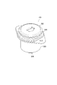
- FIG. 2 is a single perspective view of the cab mount 100.
- FIG. 3 is an exploded perspective view of the cab mount 100.
- FIG. 4 is a plan view of the cab mount 100.
- FIG. 5 is a cross-sectional view of the cab mount 100 along the F5-F5 direction of FIG.
- FIG. 6 is a diagram showing a state in which the cab mount 100 is connected to the frame 20 and the cabin 30 of the vehicle 10.
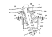
- FIG. 7 is a diagram schematically showing the shape of the cab mount 100 when the vehicle 10 collides with the barrier 70.
- FIG. 1A is a schematic side view of the vehicle 10 before the collision with the barrier 70.
- FIG. 1B is a schematic side view of the vehicle 10 after a collision with the barrier 70.
- FIG. 2 is a single perspective
- FIG. 8 is a diagram (example) of the load and the displacement (deflection) with respect to the cab mount.
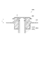
- FIG. 9 is a cross-sectional view of the cab mount 100A according to the modified example.
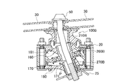
- FIG. 10 is a diagram showing a state in which the cab mount 100B according to another modification is connected to the frame 20 and the cabin 30 of the vehicle 10.
- FIG. 11 is a diagram schematically showing the shape of the cab mount 100B when the vehicle 10 collides with the barrier 70.
- FIGS. 1A and 1B are schematic side views of a vehicle 10 including a cab mount according to the present embodiment. Specifically, FIG. 1A is a schematic side view of the vehicle 10 before a collision with a barrier 70 such as concrete. FIG. 1B is a schematic side view of the vehicle 10 after a collision with the barrier 70.
- the vehicle 10 is a pickup truck.
- a pickup truck may be interpreted as a truck with an open loading platform 35 behind the cabin 30 (cab) and an engine hood 15 (bonnet).
- the same ladder frame structure as that of the vehicle 10 may be used, but the loading platform 35 is not provided.
- the cabin 30 may include a living space for occupants and a space in which a prime mover such as an engine is installed.
- the cabin 30 is connected to the frame 20 by a plurality of cab mounts 100.
- the cabin 30 moves forward in the traveling direction, specifically in the direction D1, and the energy absorption area in the front part of the cabin 30 including the engine hood 15 and the like.
- the EA absorbs the energy at the time of collision.
- FIG. 2 is a single perspective view of the cab mount 100.
- FIG. 3 is an exploded perspective view of the cab mount 100.
- the straight line L1 shown in FIG. 3 coincides with the axial direction of the cab mount 100.
- the cab mount 100 is a shear type using an elastic body 350.
- the cab mount 100 includes an inner cylinder 200 and an outer cylinder 300.
- the inner cylinder 200 and the outer cylinder 300 may be formed by using a general metal material (or resin material).
- the elastic body 350 is provided between the inner cylinder 200 and the outer cylinder 300, and holds the inner cylinder 200.
- the shear type cab mount may be interpreted as a mount in which the outer cylinder 300 is connected to the frame 20 of the vehicle 10, the inner cylinder 200 is connected to the cabin 30, and the shear deformation of the elastic body 350 is used.
- the inner cylinder 200 is divided into a plurality of pieces in the axial direction. Specifically, the inner cylinder 200 is composed of a first piece 210 and a second piece 260.
- the first piece 210 is a piece closer to the cabin 30 (upper side)
- the second piece 260 is a piece closer to the frame 20 (lower side).
- a separate plate 400 from the inner cylinder 200 is provided between the inner cylinder 200 and the cabin 30.
- the plate 400 is attached to the inner cylinder 200, specifically, the first piece 210.
- the plate 400 may be caulked and fixed to the upper peripheral edge portion of the first piece 210.
- the plate 400 may be attached to the first piece 210 by another method, for example, welding.
- the plate 400 may be integrated with the first piece 210 by forging.
- the inner cylinder 200 (first piece 210 and second piece 260) is adhered to the elastic body 350.
- the inner cylinder 200 does not necessarily have to be adhered to the elastic body 350, such as by press fitting.
- the second piece 260 is formed with another adjacent piece, specifically, an engaging portion 261 that engages with the first piece 210.
- the engaging portion 261 may be formed on the side of the first piece 210.
- the engaging portion 261 is composed of two arcuate convex shapes formed along the inner peripheral surface of the second piece 260. Such a pair of engaging portions 261 may be formed so as to face each other in the front-rear direction of the vehicle 10 when mounted on the vehicle.
- a general rubber material used for this kind of mount may be used.
- natural rubber NR
- butadiene rubber BR
- styrene butadiene rubber SBR
- butyl rubber IIR
- EPDM ethylene propylene rubber
- CR chloroprene rubber
- NBR acrylic nitrile butadiene rubber
- FIG. 4 is a plan view of the cab mount 100.
- FIG. 5 is a cross-sectional view of the cab mount 100. Specifically, FIG. 5 is a cross-sectional view of the cab mount 100 along the F5-F5 direction of FIG.
- a cavity 110 is formed in the cab mount 100 along the axial direction.
- the shaft portion of the connecting bolt 50 (not shown in FIGS. 4 and 5, see FIGS. 6 and 7) is inserted into the inner cylinder 200 (first piece 210 and second piece 260).
- the outer cylinder 300 is provided on the radial outside of the inner cylinder 200.
- the outer cylinder 300 has a cylinder portion 310 and a flange portion 320.
- the end of the inner cylinder 200 on the cabin 30 side is located closer to the cabin 30 than the end of the outer cylinder 300 on the cabin 30 side. That is, the inner cylinder 200 protrudes toward the cabin 30 from the outer cylinder 300.
- An elastic body 350 is adhered to the cylinder portion 310. It should be noted that the elastic body 350 may only be press-fitted to the extent that it cannot be easily removed from the tubular portion 310.
- the flange portion 320 is formed on the cabin 30 side (upper side) and extends radially outward from the tubular portion 310. As shown in FIG. 4, a pair of flange portions 320 are formed in the circumferential direction of the tubular portion 310, and mounting holes 325 are formed in the flange portions 320, respectively.
- the first piece 210 on the cabin 30 side is fixed to the elastic body 350.
- the term "fixation” as used herein may mean that the first piece 210 is substantially fixed by being press-fitted into the elastic body 350, or may be fixed by adhesion or the like.
- the second piece 260 does not necessarily have to be fixed (press-fitted) to the elastic body 350. That is, the engagement position P between the first piece 210 and the second piece 260 in the axial direction may be provided on the frame 20 side (lower side) of the elastic body 350 on the frame 20 side end portion (lower end portion). ..
- FIG. 6 shows a state in which the cab mount 100 is connected to the frame 20 and the cabin 30 of the vehicle 10.
- the cab mount 100 is connected to the frame 20 and the cabin 30. Specifically, the outer cylinder 300 is connected to the frame 20. Further, the inner cylinder 200 is connected to the cabin 30.
- the outer cylinder 300 is fixed to the frame 20 by the fixing bolt 41.
- the fixing bolt 41 is inserted into a mounting hole 325 (see FIGS. 4 and 5) formed in the flange portion 320 and a mounting hole (not shown) formed in the frame 20.
- a connecting bolt 50 is inserted into the inner cylinder 200 (first piece 210 and second piece 260).
- the plate 400 is arranged between the inner cylinder 200 (first piece 210) and the cabin 30 and abuts on the cabin 30.
- the connecting bolt 50 is inserted into the cavity 110 (see FIGS. 4 and 5), and the inner cylinder 200 is connected to the cabin 30 together with the plate 400 and the locking plate 25.
- the size of the locking plate 25 is preferably larger than the radial size of the outer cylinder 300.
- the outer cylinder 300 is fixed to the frame 20 by the fixing bolt 41, and the inner cylinder 200 is connected to the cabin 30 by the connecting bolt 50. Further, since the inner cylinder 200 is fixed to the elastic body 350, it does not deviate from the normal usage state (normally assumed input range) of the vehicle 10.
- FIG. 7 schematically shows the shape of the cab mount 100 when the vehicle 10 collides with the barrier 70.
- the cabin 30 also deforms and begins to fall so as to tilt forward. Therefore, the plate 400 can be deformed together with the elastic body 350.
- the first piece 210 is cut, the first piece 210 and the second piece 260 are separated, the angle of the cut is increased, and the connecting bolt 50 is pulled so as to extend. Therefore, the displacement amount of the cab mount 100 becomes large, and the movement amount of the cabin 30 becomes large.
- the inner cylinder 200 is divided into two structures, and when the vehicle 10 collides, the inner cylinder 200 and the outer cylinder 300 approach each other to the shortest distance, and the inner cylinder 200 is tilted and then at the engagement position P. Separated into a first piece 210 and a second piece 260.
- the inner cylinder is not divided and the structure integrated with the plate is widely used.
- Such a conventional cab mount has a problem that the amount of movement of the cabin 30 at the time of a collision is small and the energy absorption area EA (see FIG. 1B) at the front of the vehicle 10 cannot be sufficiently effectively used. If the amount of movement of the cabin 30 at the time of a collision is small, the impact on the inside of the cabin 30 such as the occupants is large, and it is difficult to improve the collision safety.
- FIG. 8 is a diagram (example) of the load and displacement (deflection) with respect to the cab mount. As shown in FIG. 8, when the load is on the vertical axis and the displacement (movement amount) is on the horizontal axis, the load-displacement slope is large in the conventional cab mount (see the dotted line portion in the figure).
- the bolts connecting the cab mount or the surrounding metal fittings will break, and the amount of movement of the cabin 30 will be limited (up to the position of d1 in the figure). If the amount of movement of the cabin 30 is limited, the energy absorption area EA cannot be sufficiently effectively used, and as a result, the impact on the inside of the cabin 30 such as the occupants becomes large.
- the inner cylinder moves forward with respect to the outer cylinder, and the elastic body (rubber) sandwiched between the outer cylinder and the inner cylinder is compressed. It becomes thinner and the load rises. After that, since the inner cylinder approaches the outer cylinder, the load on the cab mount (elastic body) further increases.
- the cabin moves forward and collides with the barrier 70 and deforms, the cabin tilts and the inner cylinder also tilts.
- the inner cylinder or bolt eventually breaks while the bolt for connecting the cabin also tilts.
- the displacement that is, the movement amount of the cabin 30 is increased (up to the position of d2 in the figure), and the energy is absorbed without increasing the load.
- Area EA can be used effectively. This can improve the collision safety (which may be referred to as collision performance) of the cabin 30.
- the load increases until the inner cylinder or the bolt for connecting the cabin breaks.
- the inner cylinder 200 having a split structure can increase the displacement (deflection) while suppressing the increase in the load. This makes it possible to improve collision safety by effectively utilizing the energy absorption area EA.
- the inner cylinder 200 and the separate plate 400 are provided, and the plate 400 comes into contact with the cabin 30. Therefore, it can contribute to further increase the movement amount of the cabin 30 when a large input in the front-rear direction of the vehicle is applied such as a collision of the vehicle 10. This can further enhance the collision safety of the cabin 30.
- the second piece 260 is formed with an engaging portion 261 that engages with the first piece 210. Therefore, it is possible to secure the amount of movement of the cabin 30 at the time of a collision while maintaining the coupled state of the inner cylinder 200 at the normal time.
- the engagement position P (see FIG. 5) between the first piece 210 and the second piece 260 is located on the frame 20 side (lower side) of the elastic body 350 on the frame 20 side end (lower end). It may be provided. Therefore, even when the inner cylinder 200 has a split structure, such as press-fitting the first piece 210 into the elastic body 350, the cab mount 100 can be easily manufactured.
- FIG. 9 is a cross-sectional view of the cab mount 100A according to the modified example.
- the cab mount 100A includes an inner cylinder 200A.
- the inner cylinder 200A is composed of a first piece 210A and a second piece 260A.
- the sizes (lengths) of the first piece 210A and the second piece 260A in the axial direction are different. Specifically, the length of the first piece 210A is shorter than that of the second piece 260A.
- the engagement position P between the first piece 210A and the second piece 260A in the axial direction is the end (upper end) of the cabin 30 of the inner cylinder 200A and the end (upper end) of the outer cylinder 300 on the cabin 30 side. It is preferable that at least it is provided between them. In other words, it is preferable that the engagement position P is provided in the region A1 between the lower end of the plate 400 and the upper end of the outer cylinder 300.
- the engagement position P may be provided within a range from the upper end portion of the inner cylinder 200A to 1/3 of the size (length) of the inner cylinder 200A in the axial direction.
- the moment at the time of collision can be tuned for the relationship between load and displacement (deflection).
- the inner cylinder 200 (and the inner cylinder 200A) may be divided into three or more instead of two. Further, the pieces divided into a plurality of pieces may be engaged by caulking, press-fitting, welding (arc welding or projection welding), the use of hooks, or the like, instead of the convex engaging portion 261 as described above. Further, the pair of engaging portions 261 may be formed so as to face each other in the front-rear direction of the vehicle 10, but are formed so as to face each other in the width direction of the vehicle 10 when dealing with an offset collision or the like. May be good.
- the radial outer side of the second piece 260 is a cavity (see FIG. 5), but another elastic body may be provided instead of the cavity, and the elastic body 350 is the outer cylinder 300. It may be provided up to the lower end of the.
- the cab mount 100 may be simply referred to by another name such as a mount, a cab suspension, or an anti-vibration device.
- FIG. 10 is a diagram showing a state in which the cab mount 100B according to another modified example is connected to the frame 20 and the cabin 30 of the vehicle 10.
- the cab mount 100B is a so-called liquid-sealed cab mount and includes a liquid-sealed portion 150.
- the liquid sealing unit 150 has a liquid chamber 161 and a liquid chamber 171 in which a liquid is sealed.
- the liquid chamber 161 and the liquid chamber 171 may be filled with, for example, ethylene glycol, water, silicone oil, or the like.
- the liquid sealing portion 150 is provided on the frame 20 side of the elastic body 350B.
- the liquid sealing portion 150 includes an upper lid body 160, a liquid chamber partition body 170, and a lower lid body 180.
- a liquid chamber 161 is formed between the upper lid body 160 and the liquid chamber compartment 170, and a liquid chamber 171 is formed between the liquid chamber compartment 170 and the lower lid 180.
- the liquid chamber compartment 170 may be formed with a liquid chamber 161 and a restricted passage through which the liquid enclosed in the liquid chamber 171 can pass.
- the upper lid body 160 is located closer to the frame 20.
- the lower lid 180 is farther from the frame 20 than the upper lid 160.
- the upper lid body 160, the liquid chamber partition body 170, and the lower lid body 180 are connected to the frame 20 together with the elastic body 350B by the fixing bolt 42 and the nut 43.
- the cab mount 100B is equipped with an inner cylinder 200B.
- the inner cylinder 200B has a three-part structure divided into three pieces, and is composed of a first piece 210B, a second piece 260B, and a third piece 270B.
- the axial engagement position P between the first piece 210B and the second piece 260B and the axial engagement position P between the second piece 260B and the third piece 270B are enclosed in the liquid chambers 161 and 171. It is offset from the position where it comes into contact with the liquid. That is, the first piece 210B, the second piece 260B, and the third piece 270B are engaged with each other (divided position) so as not to come into contact with the liquid.
- the axial engagement position (engagement position on the frame 20 side) between the first piece 210B and the second piece 260B may be located closer to the frame 20 than the inner surface surface (liquid chamber 161 side) of the upper lid 160. ..
- FIG. 11 is a diagram schematically showing the shape of the cab mount 100B when the vehicle 10 collides with the barrier 70.
- the inner cylinder 200B is bent so as to be scooped out.
- the inner cylinder 200B is cut, the first piece 210B and the second piece 260B are separated, the angle of being cut is increased, and the second piece 260B and the third piece 270B are further separated.
- the connecting bolt 50 is pulled so as to extend, similar to the cab mount 100 and the cab mount 100A. Therefore, the displacement amount of the cab mount 100 becomes large, and the movement amount of the cabin 30 becomes large. This can improve the collision performance of the cabin 30.
- the cab mount 100B includes a liquid sealing portion 150, and has an axial engagement position P between the first piece 210B and the second piece 260B, and an axial engagement between the second piece 260B and the third piece 270B. Since the alignment position P is offset from the position where the liquid chamber 161 and the liquid enclosed in the liquid chamber 171 are in contact with each other, the collision performance can be improved while suppressing the liquid from leaking even when the vehicle 10 collides. ..
- the cab mount 100 (and the cab mount 100A) is mounted on a vehicle other than the pickup truck or a large SUV, for example, a prime mover such as an engine. It may be applied to a cab-over type vehicle in which the cabin is located.
Landscapes
- Engineering & Computer Science (AREA)
- General Engineering & Computer Science (AREA)
- Mechanical Engineering (AREA)
- Chemical & Material Sciences (AREA)
- Combustion & Propulsion (AREA)
- Transportation (AREA)
- Physics & Mathematics (AREA)
- Acoustics & Sound (AREA)
- Aviation & Aerospace Engineering (AREA)
- Body Structure For Vehicles (AREA)
Priority Applications (1)
| Application Number | Priority Date | Filing Date | Title |
|---|---|---|---|
| JP2022565293A JPWO2022113890A1 (https=) | 2020-11-25 | 2021-11-19 |
Applications Claiming Priority (2)
| Application Number | Priority Date | Filing Date | Title |
|---|---|---|---|
| JP2020195181 | 2020-11-25 | ||
| JP2020-195181 | 2020-11-25 |
Publications (1)
| Publication Number | Publication Date |
|---|---|
| WO2022113890A1 true WO2022113890A1 (ja) | 2022-06-02 |
Family
ID=81754568
Family Applications (1)
| Application Number | Title | Priority Date | Filing Date |
|---|---|---|---|
| PCT/JP2021/042529 Ceased WO2022113890A1 (ja) | 2020-11-25 | 2021-11-19 | キャブマウント |
Country Status (2)
| Country | Link |
|---|---|
| JP (1) | JPWO2022113890A1 (https=) |
| WO (1) | WO2022113890A1 (https=) |
Citations (5)
| Publication number | Priority date | Publication date | Assignee | Title |
|---|---|---|---|---|
| JPS62202555U (https=) * | 1987-02-26 | 1987-12-24 | ||
| JPS644940U (https=) * | 1987-06-27 | 1989-01-12 | ||
| JP2006168449A (ja) * | 2004-12-14 | 2006-06-29 | Shin Caterpillar Mitsubishi Ltd | 建設機械におけるキャブ支持構造 |
| JP2012081916A (ja) * | 2010-10-14 | 2012-04-26 | Mazda Motor Corp | 車両の締結構造 |
| US20150375788A1 (en) * | 2014-06-27 | 2015-12-31 | Hyundai Motor Company | Subframe mounting bush |
-
2021
- 2021-11-19 JP JP2022565293A patent/JPWO2022113890A1/ja active Pending
- 2021-11-19 WO PCT/JP2021/042529 patent/WO2022113890A1/ja not_active Ceased
Patent Citations (5)
| Publication number | Priority date | Publication date | Assignee | Title |
|---|---|---|---|---|
| JPS62202555U (https=) * | 1987-02-26 | 1987-12-24 | ||
| JPS644940U (https=) * | 1987-06-27 | 1989-01-12 | ||
| JP2006168449A (ja) * | 2004-12-14 | 2006-06-29 | Shin Caterpillar Mitsubishi Ltd | 建設機械におけるキャブ支持構造 |
| JP2012081916A (ja) * | 2010-10-14 | 2012-04-26 | Mazda Motor Corp | 車両の締結構造 |
| US20150375788A1 (en) * | 2014-06-27 | 2015-12-31 | Hyundai Motor Company | Subframe mounting bush |
Also Published As
| Publication number | Publication date |
|---|---|
| JPWO2022113890A1 (https=) | 2022-06-02 |
Similar Documents
| Publication | Publication Date | Title |
|---|---|---|
| US9868472B2 (en) | Bonnet structure of automotive vehicle | |
| EP2121419B1 (en) | Pedestrian safe automotive hood having reinforcing foam | |
| CN114056432B (zh) | 车辆前部结构 | |
| JP6227680B2 (ja) | 車体前部構造 | |
| CN103228488B (zh) | 汽车的前部结构 | |
| CN102762886B (zh) | 隔振装置 | |
| CN107284531B (zh) | 车辆用发动机罩 | |
| JP2000002298A (ja) | エンジンマウント構造 | |
| JP5422595B2 (ja) | バンパーステイ取付構造および荷重伝達部材 | |
| KR20240093636A (ko) | 자동차의 차체 하부 구조 및 사이드 실 구조 | |
| JP2010084791A (ja) | 防振装置 | |
| KR101846566B1 (ko) | 박스형 유체 봉입 변속기 마운트 | |
| JP4788045B2 (ja) | 自動車の前部車体構造 | |
| JP5151495B2 (ja) | 自動車のフードストッパ構造 | |
| JP2020128169A (ja) | 車両用フロントフード | |
| CN105313808A (zh) | 车辆的保险杠横梁结构 | |
| WO2022113890A1 (ja) | キャブマウント | |
| CN109866826B (zh) | 车辆的车身安装托架 | |
| JP2008120256A (ja) | 車両用衝撃吸収構造 | |
| JP2016060394A (ja) | 自動車のボンネット構造 | |
| KR102457625B1 (ko) | 자동차 몸체 구조물용 보강재 | |
| JP2022090774A (ja) | キャブママウント | |
| JP6207320B2 (ja) | 防振装置 | |
| JP2017052384A (ja) | 車両の衝撃吸収構造 | |
| JP2023150837A (ja) | 車体の側部構造 |
Legal Events
| Date | Code | Title | Description |
|---|---|---|---|
| 121 | Ep: the epo has been informed by wipo that ep was designated in this application |
Ref document number: 21897864 Country of ref document: EP Kind code of ref document: A1 |
|
| ENP | Entry into the national phase |
Ref document number: 2022565293 Country of ref document: JP Kind code of ref document: A |
|
| NENP | Non-entry into the national phase |
Ref country code: DE |
|
| 122 | Ep: pct application non-entry in european phase |
Ref document number: 21897864 Country of ref document: EP Kind code of ref document: A1 |