WO2022107301A1 - ラベル付け装置、ラベル付け方法、ラベル付けプログラム及び記録媒体 - Google Patents
ラベル付け装置、ラベル付け方法、ラベル付けプログラム及び記録媒体 Download PDFInfo
- Publication number
- WO2022107301A1 WO2022107301A1 PCT/JP2020/043329 JP2020043329W WO2022107301A1 WO 2022107301 A1 WO2022107301 A1 WO 2022107301A1 JP 2020043329 W JP2020043329 W JP 2020043329W WO 2022107301 A1 WO2022107301 A1 WO 2022107301A1
- Authority
- WO
- WIPO (PCT)
- Prior art keywords
- marking
- area
- target image
- color palette
- processing unit
- Prior art date
- Legal status (The legal status is an assumption and is not a legal conclusion. Google has not performed a legal analysis and makes no representation as to the accuracy of the status listed.)
- Ceased
Links
Images


Classifications
-
- G—PHYSICS
- G06—COMPUTING OR CALCULATING; COUNTING
- G06T—IMAGE DATA PROCESSING OR GENERATION, IN GENERAL
- G06T11/00—Two-dimensional [2D] image generation
- G06T11/10—Texturing; Colouring; Generation of textures or colours
-
- G—PHYSICS
- G06—COMPUTING OR CALCULATING; COUNTING
- G06T—IMAGE DATA PROCESSING OR GENERATION, IN GENERAL
- G06T11/00—Two-dimensional [2D] image generation
- G06T11/60—Creating or editing images; Combining images with text
-
- G—PHYSICS
- G06—COMPUTING OR CALCULATING; COUNTING
- G06T—IMAGE DATA PROCESSING OR GENERATION, IN GENERAL
- G06T7/00—Image analysis
- G06T7/90—Determination of colour characteristics
-
- G—PHYSICS
- G06—COMPUTING OR CALCULATING; COUNTING
- G06V—IMAGE OR VIDEO RECOGNITION OR UNDERSTANDING
- G06V10/00—Arrangements for image or video recognition or understanding
- G06V10/20—Image preprocessing
- G06V10/25—Determination of region of interest [ROI] or a volume of interest [VOI]
-
- G—PHYSICS
- G06—COMPUTING OR CALCULATING; COUNTING
- G06V—IMAGE OR VIDEO RECOGNITION OR UNDERSTANDING
- G06V10/00—Arrangements for image or video recognition or understanding
- G06V10/70—Arrangements for image or video recognition or understanding using pattern recognition or machine learning
- G06V10/77—Processing image or video features in feature spaces; using data integration or data reduction, e.g. principal component analysis [PCA] or independent component analysis [ICA] or self-organising maps [SOM]; Blind source separation
- G06V10/774—Generating sets of training patterns; Bootstrap methods, e.g. bagging or boosting
-
- G—PHYSICS
- G06—COMPUTING OR CALCULATING; COUNTING
- G06V—IMAGE OR VIDEO RECOGNITION OR UNDERSTANDING
- G06V20/00—Scenes; Scene-specific elements
- G06V20/70—Labelling scene content, e.g. deriving syntactic or semantic representations
-
- H—ELECTRICITY
- H04—ELECTRIC COMMUNICATION TECHNIQUE
- H04N—PICTORIAL COMMUNICATION, e.g. TELEVISION
- H04N1/00—Scanning, transmission or reproduction of documents or the like, e.g. facsimile transmission; Details thereof
- H04N1/46—Colour picture communication systems
- H04N1/56—Processing of colour picture signals
- H04N1/60—Colour correction or control
-
- G—PHYSICS
- G06—COMPUTING OR CALCULATING; COUNTING
- G06V—IMAGE OR VIDEO RECOGNITION OR UNDERSTANDING
- G06V2201/00—Indexing scheme relating to image or video recognition or understanding
- G06V2201/07—Target detection
Definitions
- the present invention relates to a labeling device for labeling an area in an image, a labeling method, a labeling program, and a recording medium.
- AI Artificial Intelligence
- Patent Document 1 As a technique for labeling an image on a pixel-by-pixel basis, for example, in Patent Document 1, if there is a pixel labeled with the same color in the vicinity of the pixel to be labeled, a process of labeling the same as the pixel in the vicinity thereof is provided. The technique to be performed is described. Further, Patent Document 2 describes a Watershed algorithm that determines a boundary in an image by using a gradient of the brightness of the image.
- One aspect of the present invention has been made in view of the above problems, and one example of the present invention is a labeling device, labeling, which allows a user to efficiently label an area of an object in an image.
- the present invention is to provide a recording medium in which a method, a labeling program, and a labeling program are stored.
- the labeling device includes a display processing unit that displays a first target image and a color palette, and regions on the first target image and the color palette according to user input.
- a marking processing unit for marking is provided, and the other area is marked according to the user's input regarding one of the area on the first target image or the area on the color palette.
- the labeling method displays a first target image, displays a color palette, and marks an area on the first target image or the color palette according to user input. Includes marking the other area in response to the user's input with respect to one of the areas on the first target image or the area on the color palette.
- the labeling program includes a process of displaying a first target image on a computer, a process of displaying a color palette, and a process of displaying the first target image or the color according to user input.
- the process of marking the area on the palette and the process of marking the other area in response to the user's input regarding one of the area on the first target image or the area on the color palette are executed.
- the recording medium is a recording medium that stores a labeling program that causes a computer to function as a labeling device, and the labeling program is a process for displaying a first target image on the computer. And the process of displaying the color palette, the process of marking the area on the first target image or the area on the color palette according to the input of the user, and the process on the area on the first target image or the color palette. In response to the user's input regarding one of the areas of the above, the process of marking the other area is executed.
- a labeling device a labeling method, a labeling program, and a recording medium storing a labeling program capable of efficiently labeling an area of an object in an image are provided.
- a labeling program capable of efficiently labeling an area of an object in an image.
- the labeling device 100 according to the first exemplary embodiment will be described with reference to the drawings.
- the image actually displayed by the labeling device 100 is a color image.
- the drawings of the images described herein are black and white for convenience, and the difference in hue or saturation is represented in the drawings by the size and density of the dots and is described in words in the specification.
- the labeling device 100 is a device for the user to efficiently create teacher data to be trained by AI.
- the teacher data is data in which an area corresponding to the object is labeled in the target image including the object to be recognized by AI.
- the teacher data includes a target image and information indicating a labeled position within the target image.
- an example in which the object to be labeled is "rust" will be described, but the present embodiment is not limited to this, and labeling of various objects such as oil spilled to the sea is given. Can be used for.
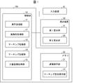
- FIG. 1 is a block configuration diagram of a labeling device 100 according to an exemplary embodiment of the present invention.
- the labeling device 100 includes a control unit 10 and a memory 20.
- the control unit 10 controls the entire labeling device 100 in an integrated manner.
- the memory 20 stores image data and marking data.
- the display device 30 displays an image and a color palette based on the control of the control unit 10.
- the input device 41 receives the user's input and outputs it to the control unit 10.
- the input device 41 can be, for example, an input device such as a touch pad, a touch panel, a mouse, or a keyboard. When the input device 41 is a touch panel, it may also serve as a display device 30.
- the control unit 10 includes a display processing unit 11, an image preprocessing unit 12, a marking processing unit 13, a marking recording unit 14, and a target image acquisition unit 15.
- the display processing unit 11 sets the first display unit 31 and the second display unit 35 on the display device 30, and displays the target image (first target image, second target image) on the first display unit 31. Then, the color palette is displayed on the second display unit 35.
- the image preprocessing unit 12 performs preprocessing of the target image.
- the marking processing unit 13 marks the other area in response to the user's input regarding one of the areas on the first target image or the area on the color palette. The details of the marking processing unit 13 will be described later.
- the marking recording unit 14 records the data in the marked area in the memory 20.
- the target image acquisition unit 15 acquires the target image from the memory 20.
- the first display unit 31 is an example of the first display area
- the second display unit 35 is an example of the second display area.
- the display area in which the target image is displayed is referred to as a "first display unit” for convenience
- the display area in which the color palette is displayed is referred to as a "second display unit” for convenience.
- the mode in which the target image is displayed on the first display unit 31 and the color palette is displayed on the second display unit 35 in one display device is described here, the first display unit 31 and the second display unit are described.
- the 35 may not be set on the same display device, but may be displayed across a plurality of display devices.
- Each unit of the control unit 10 can use a dedicated processor such as an ASIC (Application Specific Integrated Circuit) or a PLD (Programmable Logic Device). Alternatively, the entire control unit 10 may be configured by one dedicated processor. Alternatively, the programs corresponding to each part of the control unit 10 are stored in a ROM (Read Only Memory) (not shown) of the memory 20, and these programs are read out and expanded in a RAM (Random Access Memory) (not shown) of the memory 20. It may be configured to function as each part of the control unit 10 by being executed by the CPU (Central Processing Unit).
- ASIC Application Specific Integrated Circuit
- PLD Programmable Logic Device
- the entire control unit 10 may be configured by one dedicated processor.
- the programs corresponding to each part of the control unit 10 are stored in a ROM (Read Only Memory) (not shown) of the memory 20, and these programs are read out and expanded in a RAM (Random Access Memory) (not shown) of the memory 20. It may be configured to function as each part of the control unit 10 by
- the display processing unit 11 displays the first display unit 31 and the second display unit 35 on one display screen of the display device 30.
- the first display unit 31 and the second display unit 35 By displaying the first display unit 31 and the second display unit 35 on one display screen, it becomes easier to compare the target image 321 and the color palette 36, and the marking work efficiency is improved.
- the image preprocessing unit 12 can cluster the colors of the target image, for example. Clustering is an operation that reduces the amount of color classification of a target image.
- the color data of the target image has a predetermined amount of information for each pixel, but since the marking process is basically performed visually by the user, the amount of color information may be reduced. That is, the amount of color information can be reduced by clustering colors that are similar to the extent that the user cannot identify them. By such a pretreatment, the amount of processing required for the marking process can be reduced.
- the memory 20 includes an image storage unit 21 and a marking record storage unit 22.
- the image storage unit 21 stores the digital data of the target image.
- the digital data is color data of each pixel of the target image.
- the pixel color data is, for example, data in which each color of RGB is defined by 256 gradations.
- the marking record storage unit 22 accumulates and stores the colors included in the area on the color palette marked by the marking processing unit 13 in the past. Specifically, data indicating the positions of pixels in the area on the target image marked by the marking processing unit 13 and data indicating the color of the area on the color palette marked by the marking processing unit 13 are stored.
- the data indicating the positions of the pixels in the region on the target image marked by the marking processing unit 13 can be regarded as information indicating the labeled positions in the target image, and the teacher data is configured together with the target image. Can be done.
- the memory 20 may include a ROM or RAM as needed.
- the target image 32i (i is the number of target images, and the target image 321 in FIG. 2) acquired by the target image acquisition unit 15 is displayed on the first display unit 31 of the display device 30.
- the color palette 36 and the auxiliary bar 37 are displayed on the 35 by the display processing unit 11, respectively.
- the target image 321 is an image that the user labels in order to create teacher data.
- the region to be labeled is a region where rust is generated
- the target image 321 is an image including a region where rust is generated.
- the color palette 36 as the color space in this exemplary embodiment is, for example, a Lab color space.
- the Lab color space is a circular color system in which the hues of green, blue, red, and yellow are arranged in the circumferential direction and the saturations of each are arranged in the radial direction.
- the auxiliary bar 37 in this exemplary embodiment represents lightness.
- the auxiliary bar 37 may not be present.
- the display format of the color palette 36 is not limited to the exemplary color system. As for the color palette 36, one color palette 36 is used for all the target images.
- FIG. 2 is a conceptual diagram showing how the labeling device 100 is used to mark the area of the object of the target image 321.
- the target image 321 is an image taken by the antenna, and red rust spreads on the parabolic antenna with gradation. A case of marking the red rust region will be described.
- the marking processing unit 13 marks the area 501 on the target image 321 according to the input of the user.
- the term "marking” as used herein means that the user selects an area on the target image 321.
- the operation of the user and the marking processing unit 13 is also referred to as "the user marks”. It should be noted that the marking does not have to select the entire area of the object at one time, and may be a part thereof. Marking can be repeated on one target image 321.
- the method by which the user selects the region 501 is not limited, but for example, the extension of the region 501 may be specified via the input device 41, and a graphic tool capable of partitioning an arbitrary range of the image may be used. May be good.
- the display processing unit 11 superimposes the marked area 501 on the target image and displays it.
- the method by which the display processing unit 11 displays the region 501 is not limited, but for example, as shown in FIG. 2A, the region 501 may be surrounded by a dotted line, or the region 501 may have high luminance. ..
- the data indicating the position of the pixel of the region 501 marked by the user is recorded (written) in the marking record storage unit 22 by the marking recording unit 14 and stored.
- the marking processing unit 13 marks the area 601 on the color palette 36 corresponding to the color included in the area 501 on the target image 321 marked by the user.
- the term "marking” as used herein means that the marking processing unit 13 selects the color region 601 on the color palette 36.
- the operation of the marking processing unit 13 is also referred to as “marking by the marking processing unit 13”.
- the data indicating the color included in the area 601 marked on the color palette 36 is recorded and stored in the marking record storage unit 22 by the marking recording unit 14.
- the marking processing unit 13 moves on the color palette 36.
- the area 601 is marked according to the input of the user.
- the marking processing unit 13 marks the areas 501 and 502 on the target image 321 corresponding to the colors included in the area 601 marked by the user. That is, the area 501 and the area 502 of the color corresponding to the color included in the area 601 marked on the color palette 36 by the user are displayed on the target image 321.
- the data indicating the positions of the pixels in the displayed area 501 and the area 502 is recorded and stored in the marking recording / storage unit 22 by the marking recording unit 14. In FIG.
- the display processing unit 11 may highlight at least one of the partial image area and the color area marked by the marking processing unit 13, as in 501 and 601 in FIG.
- the marking processing unit 13 marks (i) the area 601 on the color palette 36 corresponding to the color included in the area 501 marked according to the user's input on the target image 321. And (ii) marking one or both of marking the area 502 on the target image 321 corresponding to the color contained in the area 601 marked according to the user's input on the color palette 36, according to the user's input. You may limit it.
- This restriction may be applied to the entire series of work in advance, or may be input by the user each time the area is marked.
- the user can select whether or not the result marked by the user in one display area is reflected in the other display area, depending on the progress of the work or the judgment of the user.
- the marking work can be efficiently performed by changing the setting according to the intention of the user.
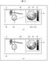
- FIG. 3 is a conceptual diagram showing how the area of another target image 322 is marked.
- the target image 322 is an image including a lock in which red rust is generated.
- the user marks the rust region 503, which is the region of the object, on the target image 322 displayed on the first display unit 31.
- the area 603 corresponding to the color included in the area 503 is marked on the color palette 36.
- the color data included in the area 603 is recorded and stored in the marking record storage unit 22 by the marking recording unit 14.
- the region 604 which is a region different from the region 603, on the color palette 36
- the region 504 corresponding to the color included in the region 604 is displayed on the target image 322. Is marked on.
- the color data included in the area 604 is recorded and stored in the marking record storage unit 22 by the marking recording unit 14.
- the position data of the pixels included in the area 504 is recorded and stored in the marking recording storage unit 22 by the marking recording unit 14. In this way, the user can not only select the already marked area, but also newly mark the area 604 of the hue considered to be the rust area on the color palette 36.
- the user repeats the above-mentioned work to perform marking processing on a plurality of target images 32i including a rust image.
- the colors included in the marked area on one or more past target images 32i are accumulated and stored in the marking record storage unit 22.
- the display processing unit 11 may display the colors included in the plurality of areas marked on one or more target images stored and stored in the marking record storage unit 22 in one color palette 36.
- the marking processing unit 13 can mark a region corresponding to a color included in the region on the color palette 36 previously marked by the marking processing unit 13 on the second target image 32i. By using this function, the burden on the user when marking the second target image 32i is reduced. The method will be described below.
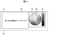
- FIG. 4 is a conceptual diagram for labeling the second target image 32i using the labeling device 100 that has accumulated data.
- the second target image 32i in which the target image acquisition unit 15 is not marked is acquired.
- the display processing unit 11 causes the first display unit 31 to display the second target image 32i. Further, the display processing unit 11 superimposes all the colors included in the plurality of areas 60X already stored in the marking record storage unit 22 on the color palette 36 and displays the second display unit 32.
- the target image 32i is marked with an area having the same color as the area 60X. Since the marking processing unit 13 marks the rusted area of the target image 32i, the burden on the user is reduced.
- the boundary of the rust image is not clear, and it is a heavy burden for the user to label the range of a large number of rust images. However, it can be determined that the same rust is generated in the region having the same hue as the region of the rust image. Therefore, as described above, the user can mark a rough area of rust, and the marking processing unit 13 can mark an area having a hue similar to that area, thereby reducing the burden on the user's labeling work. can.
- the second target image can be marked by using the accumulated past marking colors.
- the generalization performance is improved, and it is possible to improve the marking accuracy, shorten the labeling work time, and shorten the marking color correction time.
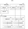
- FIG. 5 is a functional configuration diagram of the labeling device 100 and the display device 30.
- the labeling device 100 has an image reading function F10 and a marking processing function F20.
- the display device 30 has a display function F30.
- the arrows shown in FIG. 5 mainly indicate the direction of the signal or data flow, and the portion indicated by the unidirectional arrow does not exclude the bidirectionality of the signal or data. ..
- the image reading function F10 is a function F11 that reads a saved target image and displays it on the first display unit 31, and a function F12 that saves the target image read by the function F11.
- the function F12 is a storage destination of the target image.
- the marking processing function F20 includes a function F21 that preprocesses the displayed target image, a function F22 that performs marking processing of a selected area on the target image or a color palette, and recording of position information of pixels marked on the target image.
- the function F23 for reading, the function F24 for storing the position information for recording and reading by the function 23, the function F25 for recording and reading the color information of the pixel marked on the color palette, and the function F25 for recording and reading.
- the function F24 is a database of location information
- the function F26 is a database of color information.
- the display function F30 is a function F31 for displaying the target image and a function F32 for displaying the color palette.
- the target image acquisition unit 15 and the display processing unit 11 have a function F11 for reading the target image and displaying it on the first display unit 31.
- the image storage unit 21 has a function F12 for storing the target image.
- the image preprocessing unit 12 has a function F21 for preprocessing the target image.
- the marking processing unit 13 has a function F22 for performing marking processing.
- the marking recording unit 14 has a function F23 for recording and reading pixel position information and a function F25 for recording and reading pixel color information.
- the marking record storage unit 22 has a function F24 for storing position information and a function F26 for storing color information.
- the first display unit 31 has a function F31 for displaying a target image.
- the second display unit 35 has a function F32 for displaying a color palette.
- the display processing unit that displays the target image in the first display area and the color palette in the second display area, and the user's input.
- a marking processing unit for marking an area on the target image or a color palette according to the above is provided, and the marking processing unit is a color palette corresponding to a color included in the area marked on the target image according to a user's input.
- a configuration is adopted in which the upper area is marked and the area on the target image corresponding to the color included in the marked area according to the user's input is marked on the color palette. Therefore, according to the labeling device 100 according to the present exemplary embodiment, there is an effect that the user can efficiently label the area of the object in the target image.
- FIG. 6 is a preprocessing flowchart of the labeling method M100 (marking process) using the labeling device 100 according to the exemplary embodiment 1.
- the target image acquisition unit 15 acquires the first target image 321 and the display processing unit 11 causes the first display unit 31 to display the first target image 321. Further, the display processing unit 11 causes the second display unit 35 to display the color palette 36 (step S10).
- the image preprocessing unit 12 determines whether or not to execute the preprocessing of the target image 321 (step S12). Whether or not to perform preprocessing is preferably common in the processing of a series of target images 32i. That is, when preprocessing, all target images 32i are preprocessed. When no preprocessing is performed, it is preferable not to preprocess all the target images 32i.
- step S12 Whether or not to execute the preprocessing of the target image 32i may be specified by the user in advance, or may be specified by the user in the target image 321.
- step S12 the marking process proceeds to step S14, and the image preprocessing unit 12 preprocesses the target image 321.
- step S30 shown in FIG. If no pretreatment is performed in step S12 (step S12: NO), the process directly proceeds to step S30 shown in FIG. 7.
- FIG. 7 is a flowchart following FIG. 6 of the marking process of the first target image 321.
- the user marks the target image 321 or the color palette 36.
- the marking processing unit 13 determines whether or not to mark the target image 321. Specifically, the marking processing unit 13 determines whether or not the user has performed an operation for marking the target image 321.
- the process proceeds to step S34, and the marking processing unit 13 extracts the positions of the pixels in the region marked by the target image 321.
- the process proceeds to step S36, and the marking recording unit 14 records the positions of the extracted pixels in the marking recording / storage unit 22.
- the interlocking flag is the above-mentioned bidirectional marking reflection processing, that is, a color palette corresponding to the color included in the area 501 marked by the marking processing unit 13 in response to the user's input on the target image 321.
- a flag indicating whether to limit both. This flag can be set on and off by the user, for example. If the interlocking flag is on, the bidirectional marking reflection process described above is not restricted, and if the interlocking flag is off, the bidirectional marking reflection process described above is restricted.
- the interlocking flag is recorded in, for example, the memory 20.
- step S38 When the interlocking flag is on (step S38: YES), the process proceeds to step S40, and the marking processing unit 13 marks the color of the extracted pixel on the color palette 36. Next, the process proceeds to step S42, and the marking recording unit 14 records the marked color in the marking recording storage unit 22.
- the color recorded in the marking record storage unit 22 is stored as marking information (hereinafter, the color marking information is also referred to as “marking color”).
- step S54 If the interlocking flag is off in step S38 (step S38: NO), the process directly proceeds to step S54.
- step S32 if the user marks the color palette 36 in step S32 (step S32: NO), the process proceeds to step S44, and the marking processing unit 13 extracts the color of the pixel marked on the color palette 36. Next, the process proceeds to step S46, and the marking recording unit 14 records the extracted color in the marking recording storage unit 22.
- step S48 the marking processing unit 13 determines whether or not the interlocking flag is on.
- step S48: YES the process proceeds to step S50, and the marking processing unit 13 marks the extracted color on the target image 321.
- step S52 the marking recording unit 14 records the positions of the pixels of the color marked on the target image 321 in the marking recording / storage unit 22.
- step S54 the marking process proceeds to step S54. If the interlocking flag is off in step S48 (step S48: NO), the process directly proceeds to step S54.
- step S54 the marking processing unit 13 determines whether or not to continue marking. Specifically, it is determined whether or not the user has performed a marking operation on the same target image 321. If the marking is continued (step S54: YES), the process proceeds to step S30. If the marking is not continued (step S54: NO), the marking process of the first target image 321 ends.
- the case where the marking is not continued is, for example, a case where the user selects the second target image 322 and displays it on the first display unit 31.
- FIG. 6 is the same as the marking process of the first sheet.
- FIG. 8 is a flowchart following FIG. 6 for marking processing of the second and subsequent target images 322.
- the marking processing unit 13 displays marking information (marking color) on the color palette 36.
- the marking information is a color stored in the marking record storage unit 22, and is a color marked by the user in the target image 321.
- the marking processing unit 13 determines whether or not the marking information is applied (reflected) to the target image 322. Specifically, the marking processing unit 13 determines whether or not the user has performed an operation of applying the marking information to the target image 322.
- step S62 When the marking information is applied to the target image 322 (step S62: YES), the process proceeds to step S64, the marking processing unit 13 applies the marking color to the target image 322 (marking), and the marking recording unit 14 applies the marking information.
- the (marked) color is recorded in the marking record storage unit 22.
- step S62 If the marking information is not applied to the target image 322 (step S62: NO) after step S64 or in step S62, the marking process shifts to step S30.
- step S30 the same steps as those from step S30 to step S54 described with reference to FIG. 7 are executed.
- the description from step S30 to step S54 is as described with reference to FIG. 7, and is omitted here.
- step S54 If the marking is not continued in step S54 (step S54: NO), the process proceeds to step S66, and it is determined whether or not to mark the next target image.
- the next target image is marked, that is, when the user selects the next target image (step S66: YES)
- the process proceeds to step S10 of FIG. 6, and the steps of FIGS. 6 and 8 are repeated.
- step S66: NO If the user satisfies the end condition without marking the next target image (step S66: NO), the marking process ends.
- the case where the end condition is satisfied is the case where the user selects the end of the marking process, the case where the power is turned off, or the like. If the marking is continued in step S54 (step S54: YES), the process proceeds to step S62.
- marking information is accumulated in the marking record storage unit 22.
- the user does not need to mark the second target image 32i by himself / herself. Instead, the user applies the marking information to the second target image 32i to create the target image 32i in which the area of the object is marked.
- the marking record storage unit 22 can store the colors included in the area on the color palette 36 marked by the marking processing unit 13 in the past in association with arbitrary identification information.
- the marking record storage unit 22 can give a specific name to a color included in the area on the color palette 36 marked by the marking processing unit 13 in the past and store the color.
- the marking processing unit 13 marks an area corresponding to the color stored in association with a specific name (identification information) on the second target image acquired by the target image acquisition unit 15. You may. Thereby, any identification information can be associated with the accumulated past marking color and stored, and the marking color saved in association with the specific identification information can be used to mark the second target image. This makes it possible to apply an appropriate marking color. Further, for example, a plurality of types of markings can be performed in parallel.
- the target image is displayed in the first display area
- the color palette is displayed in the second display area
- the target is input according to the user's input. Marking an area on the image or color palette, this marking marks the area on the color palette corresponding to the color contained in the area marked on the target image in response to user input, and the user on the color palette.
- a configuration is adopted in which the area on the target image corresponding to the color included in the marked area is marked according to the input of. Therefore, according to the labeling method M100 according to the present exemplary embodiment, there is an effect that the user can efficiently label the area of the object in the target image.
- the labeling device 200 according to the second exemplary embodiment of the present invention will be described with reference to the drawings.
- the components having the same functions as those described in the first embodiment are designated by the same reference numerals, and the description thereof will be omitted as appropriate.
- the configuration of the labeling device 200 is basically the same as that of the labeling device 100, and the difference from the labeling device 100 is that the control unit 10 includes the target range specifying unit 16. ..
- the target range specifying unit 16 specifies the target range from the target image.
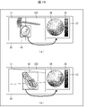
- FIG. 10 is a conceptual diagram showing how the labeling device 200 according to the second embodiment is used to mark the area of the object of the target images 321 and 322.
- the target range specifying unit 16 extracts the range of the object (parabolic antenna) in which red rust is generated from the target image 321 as the target range 40.
- the target range specifying unit 16 extracts the range of the object (lock) in which red rust is generated from the target image 322 as the target range 42.
- the target range specifying unit 16 may specify the target range according to the coordinate input of the user.
- the target range specifying unit 16 is specified from the target image by using, for example, a trained model trained in advance to detect a specific object (parabola antenna, lock, etc.) or an object detection algorithm such as pattern matching. An object may be detected and a target range may be specified according to the result.
- the target range specifying unit 16 may specify a rectangular region including a region in which a specific object (parabolic antenna, lock, etc.) is detected as the target range.
- the target range specifying unit 16 may extract the target range according to the conditions of the target (iron, metal, etc.) or the color (reddish brown, etc.) input by the user, for example. As a result, the display processing unit 11 can display the target range extracted or specified by the target range specifying unit 16.
- the display processing unit 11 constitutes a color palette from the colors included in the target range specified by the target range specifying unit 16. Specifically, the display processing unit 11 generates a color palette 38 using the colors included in the extracted target range 40. Further, the display processing unit 11 generates a color palette 39 using the colors included in the extracted target range 42.
- the marking process unit 13 marks only the area within the target range.
- the area corresponding to the color included in the area marked according to the user's input on the color palette existed outside the target area (for example, a part having the same color as rust happened to exist in the background). Even in this case, it is possible to prevent the marking processing unit 13 from marking an inappropriate area.
- FIG. 11 is a preprocessing flowchart of the marking process using the labeling device 200 according to the second embodiment. Since steps S10 to S14 of the labeling method M200 shown in FIG. 11 are the same as the pretreatment flow from step S10 to step S14 according to the labeling method M100 shown in FIG. 6, the description thereof will be omitted.
- step S16 the marking processing unit 13 determines whether or not the target range specifying unit 16 has specified the target range from the target image.
- the preprocessing flow shifts to step S18.
- step S18 the display processing unit 11 creates and displays the color palette 38 with the color types included in the target range.
- the preprocessing flow shifts to step S20.
- step S20 the display processing unit 11 creates and displays the color palette 36 with the color types included in the entire target image.
- the color types included in the target range can be narrowed down. Therefore, it is possible to generate a color palette with fine color gradation. By marking using this color palette, it is possible to accumulate marking information that defines detailed color boundaries. Therefore, in addition to the effect according to the exemplary embodiment 1, the effect that the area of the object can be labeled with high accuracy can be obtained.
- the marking information recorded in each color palette can be displayed in one color palette (standard color palette) including all colors. Therefore, by applying all the marking information displayed on the standard color palette to the second target image for marking, the user can easily perform the labeling operation.
- the marking processing unit 13 marks only the area within the target range and does not mark the area outside the target range, so that the marking process responds to the user's input on the color palette. Even when the area corresponding to the color included in the marked area exists outside the target area, it is possible to prevent the marking processing unit 13 from marking an inappropriate area.
- FIG. 12 is a diagram showing an editing function of a labeling device according to another exemplary embodiment of the present invention.
- the user marks a continuous area.
- the hue or saturation of the color contained in the continuous rust area changes slowly.
- the color palette 36 is also a color wheel having gradation, even when the color region marked by the user in the target image 321 is marked on the color palette 36, it becomes a continuous region to some extent.
- the region 501 marked by the user in the target image 321 contains a color of a region that is not rust (a color having a hue different from that of rust), that is, noise. There is.
- the noise is marked as enlave areas 601a, 601b on the color palette 36.
- the user can delete the marked areas 601a and 601b. Specifically, the user selects the areas 601a and 601b that are the excursions on the color palette 36, and presses the delete button. As a result, as shown in FIG. 12B, only the regions 601a and 601b can be deleted while leaving the region 601.
- the marking processing unit 13 may be set to delete the excursion satisfying a predetermined condition without the instruction of the user.
- the predetermined conditions are that the area is equal to or less than a predetermined value, or that the position of the excursion is separated from the main area 601 by a predetermined distance or more.
- a plurality of regions marked on the target image 321 are marked as a plurality of regions on the color palette 36. If the user determines that each of the plurality of regions on the color palette 36 is a part of a wide rust region, the user may edit to integrate the plurality of regions.
- the marking processing unit 13 receives a user's instruction and integrates a plurality of areas into one area. As a result, the area considered to be a rust image can be marked on the color palette 36 without omission.
- the marking processing unit 13 may have a function of weighting the colors stored in the marking record storage unit 22 and marking an area on the second target image based on the weighting.
- the number of times of the color marked on the color palette can be used as a weighting index.
- the marking processing unit 13 weights the colors stored by the marking record storage unit 22 based on the number of markings. For example, the marking processing unit 13 sets a certain number of times as a threshold value, and among the colors stored by the marking record storage unit 22, a color marked with a threshold value or more is specified. Then, when labeling the second target image, the marking processing unit 13 can perform marking with high accuracy by marking the area corresponding to the color specified as the color marked above the threshold value. ..
- the weighting is not limited to the method based on the number of times.
- the display processing unit 11 may display only the weighted colors in the ranking format or the top several colors based on the weights.
- the marking processing unit 13 may have a function of collectively labeling target images that have not been labeled yet. When a large number of target images are marked and the marking information is accumulated, the user does not need to perform the marking process on the second target image thereafter. In that case, the marking processing unit 13 may have a function of sequentially marking a plurality of target images collectively designated by the user. With such a configuration, it is not necessary for the user to mark one sheet at a time using the marking information, and the efficiency of the labeling work can be improved.
- the target image acquisition unit 15 acquires a plurality of second target images
- the marking processing unit 13 has a marking record storage unit 22 for the plurality of second target images acquired by the target image acquisition unit 15. It may be configured to mark the area corresponding to the stored color.
- the display processing unit 11 may have a function of selecting and displaying a display format of the color palette.
- the color palette illustrates the Lab color space.
- the display format of the color palette is not limited to this.
- FIG. 13 is a display diagram of a color palette according to another exemplary embodiment. As shown in FIG. 13, for example, the hue may be arranged in the horizontal direction and the saturation may be arranged in the vertical direction. In this way, it is possible to prepare an arbitrary display format arranged based on two or more elements selected from hue, saturation, and lightness. Then, by configuring the display format so that it can be selected from a plurality of display formats, it is possible to select a display format in which the user can easily mark the area of the object.
- FIG. 15 is a block diagram showing the configuration of the labeling device 100 according to the present embodiment. As shown in FIG. 15, the labeling device 100 includes a display processing unit 11 and a marking processing unit 13.
- the display processing unit 11 displays the target image in the first display area and displays the color palette in the second display area.
- the marking processing unit 13 marks areas on the target image and on the color palette according to the input of the user. Further, the marking processing unit 13 marks an area on the color palette corresponding to the color included in the area marked according to the user's input on the target image, and marks the area on the color palette according to the user's input. Mark the area on the target image that corresponds to the color contained in the area.
- the marking processing unit 13 can reflect the result of marking on the target image according to the user's input on the color palette, and the marking on the color palette according to the user's input.
- the result of can be reflected on the target image. That is, the marking processing unit 13 can reflect the marking of the area on the target image and the color palette according to the input of the user in both directions. This allows the user to efficiently label the area of the object in the image.
- FIG. 16 is a flowchart of a labeling method M100 (marking process) using the labeling device 100 according to the third embodiment.
- the display processing unit 11 displays the target image in the first display area and displays the color palette in the second display area (step S10).
- the marking processing unit 13 marks an area on the target image or the color palette according to the input of the user (step 30).
- step S32 the marking processing unit 13 determines whether or not the user has marked the target image.
- step S34 the marking processing unit 13 extracts the positions of the pixels in the area marked by the target image.
- step S40 the marking processing unit 13 marks the color of the extracted pixel on the color palette 36. After that, the process proceeds to step S54.
- step S32 if the user marks the color palette 36 in step S32 (step S32: NO), the process proceeds to step S44, and the marking processing unit 13 extracts the color of the pixel marked on the color palette 36.
- step S50 the marking processing unit 13 marks the extracted color on the target image. After that, the process proceeds to step S54.
- step S54 the marking processing unit 13 determines whether or not the marking is continued, that is, whether or not the marking is performed by the user in the same target image. If the marking is continued (step S54: YES), the process proceeds to step S30. If the marking is not continued (step S54: NO), the marking process of the target image ends.
- the marking of the area on the target image and the color palette according to the input of the user can be reflected in both directions, and the user can efficiently label the area of the object in the image. can.
- Each part of the control unit 10 may be realized by a logic circuit (hardware) formed in an integrated circuit (IC chip) or the like, or may be realized by software.
- the control unit 10 includes a computer C that executes an instruction of the program P, which is software that realizes each function.
- the computer C includes, for example, at least one processor (control device) C1 and at least one computer-readable recording medium M that stores the program P. Then, in the computer C, the processor C1 reads the program P from the recording medium M, stores the program P in the memory C2, and executes the program, thereby achieving the object of the present invention.
- the processor C1 for example, a CPU can be used.
- a “non-temporary tangible medium” such as a ROM, a tape, a disk, a card, a semiconductor memory, a programmable logic circuit, or the like can be used.
- a RAM or the like for expanding the program P may be further provided.
- the program P may be supplied to the computer C via an arbitrary transmission medium (communication network, broadcast wave, etc.) capable of transmitting the program P.
- a transmission medium communication network, broadcast wave, etc.
- the labeling device has a display processing unit that displays a first target image and a color palette, and marks an area on the first target image or the color palette according to user input.
- a marking processing unit is provided, and the marking processing unit marks the other area in response to the user's input regarding one of the area on the first target image or the area on the color palette.
- one marking of the area on the target image or the color palette according to the input of the user can be reflected in the other area. This allows the user to efficiently label the area of the object in the image.
- the marking processing unit is included in the area on the color palette previously marked by the marking processing unit with respect to the second target image.
- a configuration is adopted in which the area corresponding to the color to be labeled is marked.
- the second target image can be marked by using the accumulated past marking colors.
- the generalization performance is improved, and it is possible to improve the marking accuracy, shorten the labeling work time, and shorten the marking color correction time.
- a marking record storage unit that accumulates and stores the colors contained in the area on the color palette previously marked by the marking processing unit is further provided.
- the configuration of preparing is adopted.
- the marking of the second target image can be easily performed.
- the marking processing unit weights the colors stored in the marking record storage unit, and the second is based on the weighting.
- a configuration is adopted in which an area on the target image is marked.
- the second target image can be marked based on the result of weighting. Therefore, the accuracy of marking can be improved.
- the labeling device in addition to the configuration according to the fourth aspect, a configuration in which the color stored by the marking record storage unit is weighted based on the number of markings is adopted.
- the second target image can be marked based on the number of markings from the colors saved by the marking record storage unit. Therefore, the accuracy of marking can be improved.
- the marking record storage unit is a color included in the area on the color palette previously marked by the marking processing unit. Is stored in association with the identification information, and the marking processing unit marks an area corresponding to the color stored in association with the specific identification information by the marking record storage unit on the second target image.
- the configuration is adopted.
- arbitrary identification information is associated with the accumulated past marking color and saved, and the marking color saved in association with the specific identification information is used to mark the second target image. be able to. This makes it possible to apply an appropriate marking color.
- the marking processing unit stores the marking record storage unit for the plurality of the second target images.
- a configuration is adopted in which the area corresponding to the existing color is marked.
- the marking processing unit deletes the marked area on the color palette in response to the input of the user.
- the configuration is adopted.
- marking errors can be corrected and noise in the region can be removed.
- the marking processing unit responds to the input of the user, and (i) receives the input of the user on the target image.
- the area on the color palette corresponding to the color contained in the area marked accordingly is marked, and (ii) the marking processing unit marks the area on the color palette in response to the user's input.
- a configuration is adopted in which at least one of marking the area on the target image corresponding to the color included in the area is restricted.
- the marking work can be performed efficiently by changing the setting according to the user's intention.
- a target range specifying unit for specifying the target range is further provided in the target image, and the marking processing unit is the target.
- a configuration is adopted in which the area within the range is marked.
- the range of the marking area can be narrowed down. Therefore, the user's marking work can be made more efficient.
- the color palette is composed of colors included in the target range specified by the target range specifying unit. There is.
- the types of colors displayed in the color palette can be reduced. Therefore, the range of colors to be marked can be finely selected.
- the target range specifying unit specifies the target range according to the result of detecting a specific object from the target image. Has been adopted.
- the target range can be specified appropriately and efficiently.
- one marking of the area on the target image or the color palette according to the input of the user can be reflected in the other area. This allows the user to efficiently label the area of the object in the image.
- the labeling program according to aspect 14 has a process of displaying a first target image on a computer, a process of displaying a color palette, and a process of displaying the first target image or the color palette according to user input.
- the process of marking the area and the process of marking the other area in response to the user's input regarding one of the area on the first target image or the area on the color palette are executed.
- the marking of the area on the target image and the color palette according to the input of the user can be reflected in both directions.
- the marking of one of the areas on the target image or the color palette according to the input of the user can be reflected in the other area.
- the present invention also includes a computer-readable non-temporary recording medium that stores the above labeling program.
Landscapes
- Engineering & Computer Science (AREA)
- Theoretical Computer Science (AREA)
- Physics & Mathematics (AREA)
- General Physics & Mathematics (AREA)
- Multimedia (AREA)
- Computational Linguistics (AREA)
- Computer Vision & Pattern Recognition (AREA)
- Artificial Intelligence (AREA)
- Health & Medical Sciences (AREA)
- Computing Systems (AREA)
- Databases & Information Systems (AREA)
- Evolutionary Computation (AREA)
- General Health & Medical Sciences (AREA)
- Medical Informatics (AREA)
- Software Systems (AREA)
- Signal Processing (AREA)
- Image Analysis (AREA)
- User Interface Of Digital Computer (AREA)
- Processing Or Creating Images (AREA)
Priority Applications (3)
| Application Number | Priority Date | Filing Date | Title |
|---|---|---|---|
| JP2022563518A JP7571795B2 (ja) | 2020-11-20 | 2020-11-20 | ラベル付け装置、ラベル付け方法、ラベル付けプログラム及び記録媒体 |
| US18/036,838 US20230410388A1 (en) | 2020-11-20 | 2020-11-20 | Labeling device, labeling method, labeling program, and recording medium |
| PCT/JP2020/043329 WO2022107301A1 (ja) | 2020-11-20 | 2020-11-20 | ラベル付け装置、ラベル付け方法、ラベル付けプログラム及び記録媒体 |
Applications Claiming Priority (1)
| Application Number | Priority Date | Filing Date | Title |
|---|---|---|---|
| PCT/JP2020/043329 WO2022107301A1 (ja) | 2020-11-20 | 2020-11-20 | ラベル付け装置、ラベル付け方法、ラベル付けプログラム及び記録媒体 |
Publications (1)
| Publication Number | Publication Date |
|---|---|
| WO2022107301A1 true WO2022107301A1 (ja) | 2022-05-27 |
Family
ID=81708576
Family Applications (1)
| Application Number | Title | Priority Date | Filing Date |
|---|---|---|---|
| PCT/JP2020/043329 Ceased WO2022107301A1 (ja) | 2020-11-20 | 2020-11-20 | ラベル付け装置、ラベル付け方法、ラベル付けプログラム及び記録媒体 |
Country Status (3)
| Country | Link |
|---|---|
| US (1) | US20230410388A1 (https=) |
| JP (1) | JP7571795B2 (https=) |
| WO (1) | WO2022107301A1 (https=) |
Cited By (1)
| Publication number | Priority date | Publication date | Assignee | Title |
|---|---|---|---|---|
| WO2025062967A1 (ja) * | 2023-09-22 | 2025-03-27 | オムロン株式会社 | アノテーション支援装置及びアノテーション支援方法 |
Citations (5)
| Publication number | Priority date | Publication date | Assignee | Title |
|---|---|---|---|---|
| JP2006157892A (ja) * | 2004-11-01 | 2006-06-15 | Canon Inc | 画像処理装置及び画像処理方法 |
| JP2007221694A (ja) * | 2006-02-20 | 2007-08-30 | Seiko Epson Corp | 画像編集装置、画像編集方法、画像編集プログラム、画像読み取りシステム、および、画像読み取り方法 |
| JP2011010175A (ja) * | 2009-06-29 | 2011-01-13 | Kyocera Mita Corp | 画像処理プログラム |
| JP2012157080A (ja) * | 2007-08-07 | 2012-08-16 | Canon Inc | 画像処理装置及び画像処理方法 |
| JP2012239040A (ja) * | 2011-05-12 | 2012-12-06 | Sharp Corp | 操作装置、及びそれを備える画像処理装置 |
-
2020
- 2020-11-20 WO PCT/JP2020/043329 patent/WO2022107301A1/ja not_active Ceased
- 2020-11-20 JP JP2022563518A patent/JP7571795B2/ja active Active
- 2020-11-20 US US18/036,838 patent/US20230410388A1/en active Pending
Patent Citations (5)
| Publication number | Priority date | Publication date | Assignee | Title |
|---|---|---|---|---|
| JP2006157892A (ja) * | 2004-11-01 | 2006-06-15 | Canon Inc | 画像処理装置及び画像処理方法 |
| JP2007221694A (ja) * | 2006-02-20 | 2007-08-30 | Seiko Epson Corp | 画像編集装置、画像編集方法、画像編集プログラム、画像読み取りシステム、および、画像読み取り方法 |
| JP2012157080A (ja) * | 2007-08-07 | 2012-08-16 | Canon Inc | 画像処理装置及び画像処理方法 |
| JP2011010175A (ja) * | 2009-06-29 | 2011-01-13 | Kyocera Mita Corp | 画像処理プログラム |
| JP2012239040A (ja) * | 2011-05-12 | 2012-12-06 | Sharp Corp | 操作装置、及びそれを備える画像処理装置 |
Cited By (1)
| Publication number | Priority date | Publication date | Assignee | Title |
|---|---|---|---|---|
| WO2025062967A1 (ja) * | 2023-09-22 | 2025-03-27 | オムロン株式会社 | アノテーション支援装置及びアノテーション支援方法 |
Also Published As
| Publication number | Publication date |
|---|---|
| JP7571795B2 (ja) | 2024-10-23 |
| JPWO2022107301A1 (https=) | 2022-05-27 |
| US20230410388A1 (en) | 2023-12-21 |
Similar Documents
| Publication | Publication Date | Title |
|---|---|---|
| US9786031B2 (en) | Distortion of digital images using spatial offsets from image reference points | |
| US8041122B2 (en) | Image processing apparatus, method for controlling image processing apparatus, and storage medium storing related program | |
| JP2776295B2 (ja) | 画像インデックス生成方法及び画像インデックス生成装置 | |
| US6577759B1 (en) | System and method for performing region-based image retrieval using color-based segmentation | |
| KR100667663B1 (ko) | 화상 처리 장치, 화상 처리 방법 및 그 프로그램을 기록한 컴퓨터 판독 가능한 기록매체 | |
| JP2008085695A (ja) | 電子透かし埋め込み装置および検出装置 | |
| US20090010541A1 (en) | Image processing method | |
| US5526020A (en) | Image editing system and method having improved automatic object selection | |
| JP2005150855A (ja) | カラー画像の圧縮方法及びカラー画像圧縮装置 | |
| JP2015011585A (ja) | 画像処理装置、画像形成装置、画像形成システム、画像処理方法およびプログラム | |
| JP4230730B2 (ja) | 画像処理システム及び画像処理方法 | |
| WO2022107301A1 (ja) | ラベル付け装置、ラベル付け方法、ラベル付けプログラム及び記録媒体 | |
| JP4370950B2 (ja) | 画像処理装置 | |
| JP4182891B2 (ja) | 画像処理装置 | |
| JP4149464B2 (ja) | 画像処理装置 | |
| JP2007043506A (ja) | 画像処理装置及びその画像処理方法、プログラム並びに記憶媒体 | |
| JPH11123289A (ja) | 刺繍データ処理装置及び刺繍ミシン並びに記録媒体 | |
| JP4080157B2 (ja) | 画像処理装置、画像処理方法、及び記録媒体 | |
| JP2005269269A (ja) | 画像処理装置 | |
| US20250391072A1 (en) | Color enhancement of digital images to match a template | |
| JP4311183B2 (ja) | 画像処理装置及びプログラム | |
| JP4182873B2 (ja) | 画像処理装置及びプログラム | |
| JP2007109178A (ja) | 画像処理装置及びその制御方法、プログラム | |
| JP4329564B2 (ja) | 画像処理装置 | |
| JP2005184403A (ja) | 画像処理装置 |
Legal Events
| Date | Code | Title | Description |
|---|---|---|---|
| 121 | Ep: the epo has been informed by wipo that ep was designated in this application |
Ref document number: 20962464 Country of ref document: EP Kind code of ref document: A1 |
|
| ENP | Entry into the national phase |
Ref document number: 2022563518 Country of ref document: JP Kind code of ref document: A |
|
| WWE | Wipo information: entry into national phase |
Ref document number: 18036838 Country of ref document: US |
|
| NENP | Non-entry into the national phase |
Ref country code: DE |
|
| 122 | Ep: pct application non-entry in european phase |
Ref document number: 20962464 Country of ref document: EP Kind code of ref document: A1 |