〔実施形態1〕
以下に、第1の例示的実施形態に係るラベル付け装置100について、図面を参照して説明する。なお、ラベル付け装置100によって実際に表示される画像はカラー画像である。しかし、本明細書で説明する画像の図面は便宜上白黒であり、色相又は彩度の違いは図面においてはドットの大きさと密度で表現するとともに、明細書において言葉で説明している。
[Embodiment 1]
Hereinafter, the labeling device 100 according to the first exemplary embodiment will be described with reference to the drawings. The image actually displayed by the labeling device 100 is a color image. However, the drawings of the images described herein are black and white for convenience, and the difference in hue or saturation is represented in the drawings by the size and density of the dots and is described in words in the specification.
(ラベル付け装置の構成)
ラベル付け装置100の構成について、図面を参照して説明する。ラベル付け装置100は、AIに学習させる教師データをユーザが効率的に作成するための装置である。当該教師データは、AIに認識させる対象物を含む対象画像において、当該対象物に対応する領域をラベル付けしたデータである。一例において、教師データは、対象画像と、当該対象画像内においてラベル付けされた位置を示す情報とを含む。なお、以下の実施形態では、ラベル付けする対象物が「錆」である例について説明するが、本実施形態はこれに限定されず、例えば、海上に流出した油分など様々な対象物のラベル付けに使用することができる。
(Configuration of labeling device)
The configuration of the labeling device 100 will be described with reference to the drawings. The labeling device 100 is a device for the user to efficiently create teacher data to be trained by AI. The teacher data is data in which an area corresponding to the object is labeled in the target image including the object to be recognized by AI. In one example, the teacher data includes a target image and information indicating a labeled position within the target image. In the following embodiment, an example in which the object to be labeled is "rust" will be described, but the present embodiment is not limited to this, and labeling of various objects such as oil spilled to the sea is given. Can be used for.
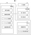
図1は、本発明の例示的実施形態に係るラベル付け装置100のブロック構成図である。図1に示すように、ラベル付け装置100は、制御部10と、メモリ20と、を備える。制御部10は、ラベル付け装置100の全体を統括制御する。メモリ20は、画像データ及びマーキングデータを保存する。表示装置30は、制御部10の制御に基づき、画像とカラーパレットとを表示する。入力装置41は、ユーザの入力を受け付け、制御部10に出力する。入力装置41は、例えば、タッチパッド、タッチパネル、マウス、キーボード等の入力デバイスであり得る。入力装置41がタッチパネルである場合、表示装置30を兼ねてもよい。
FIG. 1 is a block configuration diagram of a labeling device 100 according to an exemplary embodiment of the present invention. As shown in FIG. 1, the labeling device 100 includes a control unit 10 and a memory 20. The control unit 10 controls the entire labeling device 100 in an integrated manner. The memory 20 stores image data and marking data. The display device 30 displays an image and a color palette based on the control of the control unit 10. The input device 41 receives the user's input and outputs it to the control unit 10. The input device 41 can be, for example, an input device such as a touch pad, a touch panel, a mouse, or a keyboard. When the input device 41 is a touch panel, it may also serve as a display device 30.
制御部10は、表示処理部11、画像前処理部12、マーキング処理部13、マーキング記録部14、及び対象画像取得部15を備える。表示処理部11は、表示装置30に、第1表示部31と第2表示部35を設定して、第1表示部31に対象画像(第1の対象画像、第2の対象画像)を表示し、第2表示部35にカラーパレットを表示する。画像前処理部12は、対象画像の前処理を行う。マーキング処理部13は、第1の対象画像上の領域又はカラーパレット上の領域の一方に関するユーザの入力に応じて、他方の領域をマーキングする。マーキング処理部13の詳細については後述する。マーキング記録部14は、マーキングされた領域のデータをメモリ20に記録する。対象画像取得部15は、対象画像をメモリ20から取得する。第1表示部31は、第1の表示領域の一例であり、第2表示部35は、第2の表示領域の一例である。
The control unit 10 includes a display processing unit 11, an image preprocessing unit 12, a marking processing unit 13, a marking recording unit 14, and a target image acquisition unit 15. The display processing unit 11 sets the first display unit 31 and the second display unit 35 on the display device 30, and displays the target image (first target image, second target image) on the first display unit 31. Then, the color palette is displayed on the second display unit 35. The image preprocessing unit 12 performs preprocessing of the target image. The marking processing unit 13 marks the other area in response to the user's input regarding one of the areas on the first target image or the area on the color palette. The details of the marking processing unit 13 will be described later. The marking recording unit 14 records the data in the marked area in the memory 20. The target image acquisition unit 15 acquires the target image from the memory 20. The first display unit 31 is an example of the first display area, and the second display unit 35 is an example of the second display area.
なお、ここでは、対象画像が表示される表示領域を便宜上「第1表示部」と呼び、カラーパレットが表示される表示領域を便宜上「第2表示部」と呼んでいる。また、ここでは一つの表示装置における第1表示部31に対象画像を表示し、第2表示部35にカラーパレットを表示する形態について説明しているが、第1表示部31と第2表示部35とは、同一の表示装置に設定されなくても、複数の表示装置にわたって表示されてもよい。
Here, the display area in which the target image is displayed is referred to as a "first display unit" for convenience, and the display area in which the color palette is displayed is referred to as a "second display unit" for convenience. Further, although the mode in which the target image is displayed on the first display unit 31 and the color palette is displayed on the second display unit 35 in one display device is described here, the first display unit 31 and the second display unit are described. The 35 may not be set on the same display device, but may be displayed across a plurality of display devices.
制御部10の各部は、それぞれごとにASIC(Application Specific Integrated Circuit)又はPLD(Programmable Logic Device)等の専用プロセッサを用いることができる。又は、制御部10の全体を1つの専用プロセッサで構成してもよい。あるいは、制御部10の各部に対応するプログラムをメモリ20の図示しないROM(Read Only Memory)に記憶させておき、これらのプログラムを読み出してメモリ20の図示しないRAM(Random Access Memory)に展開してCPU(Central Processing Unit)が実行することにより、制御部10の各部として機能させる構成でもよい。
Each unit of the control unit 10 can use a dedicated processor such as an ASIC (Application Specific Integrated Circuit) or a PLD (Programmable Logic Device). Alternatively, the entire control unit 10 may be configured by one dedicated processor. Alternatively, the programs corresponding to each part of the control unit 10 are stored in a ROM (Read Only Memory) (not shown) of the memory 20, and these programs are read out and expanded in a RAM (Random Access Memory) (not shown) of the memory 20. It may be configured to function as each part of the control unit 10 by being executed by the CPU (Central Processing Unit).
表示処理部11は、表示装置30の1つの表示画面に第1表示部31と第2表示部35とを表示することが好ましい。1つの表示画面に第1表示部31と第2表示部35とを表示することにより、対象画像321とカラーパレット36とを比較しやすくなり、マーキングの作業効率が向上する。
It is preferable that the display processing unit 11 displays the first display unit 31 and the second display unit 35 on one display screen of the display device 30. By displaying the first display unit 31 and the second display unit 35 on one display screen, it becomes easier to compare the target image 321 and the color palette 36, and the marking work efficiency is improved.
画像前処理部12は、例えば、対象画像の色をクラスタリングすることができる。クラスタリングは、対象画像の色の分類量を減らす操作である。対象画像の色データは画素ごとに所定の情報量を有しているが、マーキング処理は基本的にユーザの目視によって行われるため、色の情報量を少なくしてもよい。つまり、ユーザが識別できない程度に類似する色をクラスタリングによりまとめることで、色の情報量を少なくすることができる。このような前処理により、マーキング処理に要する処理量を減らすことができる。
The image preprocessing unit 12 can cluster the colors of the target image, for example. Clustering is an operation that reduces the amount of color classification of a target image. The color data of the target image has a predetermined amount of information for each pixel, but since the marking process is basically performed visually by the user, the amount of color information may be reduced. That is, the amount of color information can be reduced by clustering colors that are similar to the extent that the user cannot identify them. By such a pretreatment, the amount of processing required for the marking process can be reduced.
メモリ20は、画像保存部21、及びマーキング記録保存部22を備える。画像保存部21は、対象画像のデジタルデータを保存する。デジタルデータは、対象画像の各画素の色データである。画素の色データは、例えば、RGBの各色を256階調で規定したデータである。マーキング記録保存部22は、過去にマーキング処理部13がマーキングしたカラーパレット上の領域に含まれる色を蓄積して保存する。具体的には、マーキング処理部13がマーキングした対象画像上の領域の画素の位置を示すデータ、及び、マーキング処理部13がマーキングしたカラーパレット上の領域の色を示すデータを保存する。マーキング処理部13がマーキングした対象画像上の領域の画素の位置を示すデータは、対象画像内においてラベル付けされた位置を示す情報とみなすことができ、対象画像と併せて教師データを構成することができる。なお、メモリ20は、これら以外にも、必要に応じROM又はRAMを備えていてもよい。
The memory 20 includes an image storage unit 21 and a marking record storage unit 22. The image storage unit 21 stores the digital data of the target image. The digital data is color data of each pixel of the target image. The pixel color data is, for example, data in which each color of RGB is defined by 256 gradations. The marking record storage unit 22 accumulates and stores the colors included in the area on the color palette marked by the marking processing unit 13 in the past. Specifically, data indicating the positions of pixels in the area on the target image marked by the marking processing unit 13 and data indicating the color of the area on the color palette marked by the marking processing unit 13 are stored. The data indicating the positions of the pixels in the region on the target image marked by the marking processing unit 13 can be regarded as information indicating the labeled positions in the target image, and the teacher data is configured together with the target image. Can be done. In addition to these, the memory 20 may include a ROM or RAM as needed.
図2に示すように、表示装置30の第1表示部31には対象画像取得部15が取得した対象画像32i(iは対象画像の枚数、図2では対象画像321)が、第2表示部35にはカラーパレット36と補助バー37が、表示処理部11によりそれぞれ表示される。対象画像321は、教師データを作成するために、ユーザがラベル付けを行う画像である。本例示的実施形態では、ラベル付けの対象となる領域は、錆が発生している領域であり、対象画像321は、錆が発生している領域を含む画像である。
As shown in FIG. 2, the target image 32i (i is the number of target images, and the target image 321 in FIG. 2) acquired by the target image acquisition unit 15 is displayed on the first display unit 31 of the display device 30. The color palette 36 and the auxiliary bar 37 are displayed on the 35 by the display processing unit 11, respectively. The target image 321 is an image that the user labels in order to create teacher data. In this exemplary embodiment, the region to be labeled is a region where rust is generated, and the target image 321 is an image including a region where rust is generated.
本例示的実施形態における色空間としてのカラーパレット36は、例えば、Lab色空間である。Lab色空間は、緑、青、赤、黄の色相を円周方向に、それぞれの彩度を半径方向に配列した円形の表色系である。また、本例示的実施形態における補助バー37は、明度を表す。補助バー37はなくてもよい。なお、カラーパレット36の表示形式は、例示の表色系に限られない。カラーパレット36は、すべての対象画像に対して1つのカラーパレット36が使用される。
The color palette 36 as the color space in this exemplary embodiment is, for example, a Lab color space. The Lab color space is a circular color system in which the hues of green, blue, red, and yellow are arranged in the circumferential direction and the saturations of each are arranged in the radial direction. Further, the auxiliary bar 37 in this exemplary embodiment represents lightness. The auxiliary bar 37 may not be present. The display format of the color palette 36 is not limited to the exemplary color system. As for the color palette 36, one color palette 36 is used for all the target images.
(マーキング処理部)
次に、マーキング処理部13の詳細について、図面を参照して説明する。図2は、ラベル付け装置100を用いて対象画像321の対象物の領域をマーキングする様子を示す概念図である。対象画像321は、アンテナが撮影された画像であるが、そのうちのパラボラアンテナに赤錆がグラディエーションを持って広がっている。この赤錆の領域をマーキングする場合について説明する。
(Marking processing unit)
Next, the details of the marking processing unit 13 will be described with reference to the drawings. FIG. 2 is a conceptual diagram showing how the labeling device 100 is used to mark the area of the object of the target image 321. The target image 321 is an image taken by the antenna, and red rust spreads on the parabolic antenna with gradation. A case of marking the red rust region will be described.
図2(a)に示すように、マーキング処理部13は、対象画像321上において、ユーザの入力に応じて領域501をマーキングする。ここでいう「マーキング」とは、ユーザが対象画像321上の領域を選択することを意味する。以下、このユーザとマーキング処理部13の動作を「ユーザがマーキングする」とも称する。なお、マーキングは、一度に対象物の領域の全てを選択する必要はなく、一部分であってもよい。1枚の対象画像321において、マーキングは繰り返し実行することが可能である。
As shown in FIG. 2A, the marking processing unit 13 marks the area 501 on the target image 321 according to the input of the user. The term "marking" as used herein means that the user selects an area on the target image 321. Hereinafter, the operation of the user and the marking processing unit 13 is also referred to as "the user marks". It should be noted that the marking does not have to select the entire area of the object at one time, and may be a part thereof. Marking can be repeated on one target image 321.
ユーザが領域501を選択する方法は限定されないが、例えば、入力装置41を介して領域501の外延を指定してもよく、また、画像の任意の範囲を区画することができるグラフィックツールを用いてもよい。
The method by which the user selects the region 501 is not limited, but for example, the extension of the region 501 may be specified via the input device 41, and a graphic tool capable of partitioning an arbitrary range of the image may be used. May be good.
また、表示処理部11は、マーキングされた領域501を対象画像に重畳して表示する。表示処理部11が領域501を表示する方法は限定されないが、例えば、図2(a)に示すように、領域501を点線で囲むことでもよく、あるいは領域501を高輝度にすること等でもよい。ユーザがマーキングした領域501の画素の位置を示すデータは、マーキング記録部14により、マーキング記録保存部22に記録(書き込み)され、保存される。
Further, the display processing unit 11 superimposes the marked area 501 on the target image and displays it. The method by which the display processing unit 11 displays the region 501 is not limited, but for example, as shown in FIG. 2A, the region 501 may be surrounded by a dotted line, or the region 501 may have high luminance. .. The data indicating the position of the pixel of the region 501 marked by the user is recorded (written) in the marking record storage unit 22 by the marking recording unit 14 and stored.
また、マーキング処理部13は、ユーザがマーキングした対象画像321上の領域501に含まれる色に対応するカラーパレット36上の領域601をマーキングする。ここでいう「マーキング」とは、マーキング処理部13がカラーパレット36上の色の領域601を選択することである。以下、このマーキング処理部13の動作を「マーキング処理部13がマーキングする」とも称する。カラーパレット36上にマーキングされた領域601に含まれる色を示すデータは、マーキング記録部14により、マーキング記録保存部22に記録され、保存される。
Further, the marking processing unit 13 marks the area 601 on the color palette 36 corresponding to the color included in the area 501 on the target image 321 marked by the user. The term "marking" as used herein means that the marking processing unit 13 selects the color region 601 on the color palette 36. Hereinafter, the operation of the marking processing unit 13 is also referred to as “marking by the marking processing unit 13”. The data indicating the color included in the area 601 marked on the color palette 36 is recorded and stored in the marking record storage unit 22 by the marking recording unit 14.
逆に、図2(b)に示すように、ユーザがカラーパレット36上の領域601をマーキング(この場合は、すでにマーキングされた領域601を選択)すると、マーキング処理部13は、カラーパレット36上において、ユーザの入力に応じて領域601をマーキングする。さらに、マーキング処理部13は、ユーザがマーキングした領域601に含まれる色に対応する対象画像321上の領域501、502をマーキングする。つまり、ユーザがカラーパレット36上でマーキングした領域601に含まれる色に対応する色の領域501と領域502が、対象画像321上に表示される。表示された領域501と領域502の画素の位置を示すデータは、マーキング記録部14により、マーキング記録保存部22に記録され、保存される。図2(b)で、領域601に含まれる色に対応する領域が、領域501と領域502の2か所に表示される理由は、同じ色相の錆が2か所で発生しているためである。このとき、表示処理部11は、図2の501及び601のように、マーキング処理部13によりマーキングされる部分画像領域及び色領域の少なくとも一方を強調表示してもよい。
Conversely, as shown in FIG. 2B, when the user marks the area 601 on the color palette 36 (in this case, the already marked area 601 is selected), the marking processing unit 13 moves on the color palette 36. In, the area 601 is marked according to the input of the user. Further, the marking processing unit 13 marks the areas 501 and 502 on the target image 321 corresponding to the colors included in the area 601 marked by the user. That is, the area 501 and the area 502 of the color corresponding to the color included in the area 601 marked on the color palette 36 by the user are displayed on the target image 321. The data indicating the positions of the pixels in the displayed area 501 and the area 502 is recorded and stored in the marking recording / storage unit 22 by the marking recording unit 14. In FIG. 2B, the reason why the regions corresponding to the colors included in the region 601 are displayed in two locations, the region 501 and the region 502, is that rust of the same hue occurs in the two locations. be. At this time, the display processing unit 11 may highlight at least one of the partial image area and the color area marked by the marking processing unit 13, as in 501 and 601 in FIG.
なお、上述したような、マーキング処理部13が、(i)対象画像321上においてユーザの入力に応じてマーキングした領域501に含まれる色に対応するカラーパレット36上の領域601をマーキングすること、および、(ii)カラーパレット36上においてユーザの入力に応じてマーキングした領域601に含まれる色に対応する対象画像321上の領域502をマーキングすることの一方または両方を、ユーザの入力に応じて制限してもよい。
As described above, the marking processing unit 13 marks (i) the area 601 on the color palette 36 corresponding to the color included in the area 501 marked according to the user's input on the target image 321. And (ii) marking one or both of marking the area 502 on the target image 321 corresponding to the color contained in the area 601 marked according to the user's input on the color palette 36, according to the user's input. You may limit it.
この制限は、予め一連の作業全体に適用させてもよく、又は領域をマーキングするごとにユーザが入力してもよい。このように構成することで、作業の進捗により、又はユーザの判断により、ユーザが一方の表示領域においてマーキングした結果を他方の表示領域に反映させるかどうかをユーザが選択することができる。これにより、ユーザの意図により設定を変更することで、マーキング作業を効率的に行うことができる。
This restriction may be applied to the entire series of work in advance, or may be input by the user each time the area is marked. With this configuration, the user can select whether or not the result marked by the user in one display area is reflected in the other display area, depending on the progress of the work or the judgment of the user. As a result, the marking work can be efficiently performed by changing the setting according to the intention of the user.
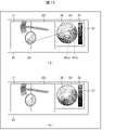
図3は、他の対象画像322の領域をマーキングする様子を示す概念図である。対象画像322は、赤錆が発生した錠前を含む画像である。図3(a)に示すように、ユーザは、第1表示部31に表示された対象画像322上で、対象物の領域である錆の領域503をマーキングする。すると、カラーパレット36上に、領域503に含まれる色に対応する領域603がマーキングされる。領域603に含まれる色のデータは、マーキング記録部14により、マーキング記録保存部22に記録され、保存される。
FIG. 3 is a conceptual diagram showing how the area of another target image 322 is marked. The target image 322 is an image including a lock in which red rust is generated. As shown in FIG. 3A, the user marks the rust region 503, which is the region of the object, on the target image 322 displayed on the first display unit 31. Then, the area 603 corresponding to the color included in the area 503 is marked on the color palette 36. The color data included in the area 603 is recorded and stored in the marking record storage unit 22 by the marking recording unit 14.
また、図3(b)に示すように、ユーザがカラーパレット36上に、領域603とは異なる領域である領域604をマーキングすると、領域604に含まれる色に対応する領域504が対象画像322上にマーキングされる。領域604に含まれる色のデータは、マーキング記録部14により、マーキング記録保存部22に記録され、保存される。また、領域504に含まれる画素の位置データは、マーキング記録部14により、マーキング記録保存部22に記録され、保存される。このように、ユーザは、すでにマーキングされた領域を選択するだけでなく、錆領域と考えられる色相の領域604を新たにカラーパレット36上でマーキングすることも可能である。
Further, as shown in FIG. 3B, when the user marks the region 604, which is a region different from the region 603, on the color palette 36, the region 504 corresponding to the color included in the region 604 is displayed on the target image 322. Is marked on. The color data included in the area 604 is recorded and stored in the marking record storage unit 22 by the marking recording unit 14. Further, the position data of the pixels included in the area 504 is recorded and stored in the marking recording storage unit 22 by the marking recording unit 14. In this way, the user can not only select the already marked area, but also newly mark the area 604 of the hue considered to be the rust area on the color palette 36.
ユーザは上述のような作業を繰り返して、錆画像を含む複数の対象画像32iにマーキング処理を行う。これにより、過去の1以上の対象画像32i上においてマーキングされた領域に含まれる色が、マーキング記録保存部22に蓄積して保存される。対象画像取得部15がマーキングされていない新たな対象画像(第2の対象画像)32iを取得し、表示処理部11が当該第2の対象画像32iおよびカラーパレット36を表示させるとき、表示処理部11は、マーキング記録保存部22に蓄積して保存された、1以上の対象画像上でマーキングした複数の領域に含まれる色を、1つのカラーパレット36に表示してもよい。また、マーキング処理部13は、第2の対象画像32iに対して、過去にマーキング処理部13がマーキングしたカラーパレット36上の領域に含まれる色に対応する領域をマーキングすることができる。この機能を用いることにより、第2の対象画像32iにマーキングする際のユーザの負担が軽減される。以下、その方法について説明する。
The user repeats the above-mentioned work to perform marking processing on a plurality of target images 32i including a rust image. As a result, the colors included in the marked area on one or more past target images 32i are accumulated and stored in the marking record storage unit 22. When the target image acquisition unit 15 acquires a new target image (second target image) 32i without marking and the display processing unit 11 displays the second target image 32i and the color palette 36, the display processing unit 11 may display the colors included in the plurality of areas marked on one or more target images stored and stored in the marking record storage unit 22 in one color palette 36. Further, the marking processing unit 13 can mark a region corresponding to a color included in the region on the color palette 36 previously marked by the marking processing unit 13 on the second target image 32i. By using this function, the burden on the user when marking the second target image 32i is reduced. The method will be described below.
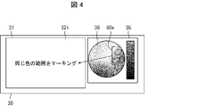
図4は、データを蓄積したラベル付け装置100を用いて第2の対象画像32iのラベル付けを行う概念図である。まず、対象画像取得部15がマーキングされていない第2の対象画像32iを取得する。表示処理部11は、第2の対象画像32iを第1表示部31に表示させる。また、表示処理部11は、すでにマーキング記録保存部22に保存された複数の領域60Xに含まれる色をすべてカラーパレット36に重畳させて第2表示部32表示させる。ユーザが領域60Xをすべて選択して、対象画像32iに反映させると、対象画像32iに領域60Xの色と同じ色の領域がマーキングされる。マーキング処理部13が対象画像32iの錆領域をマーキングするため、ユーザの負担が軽減される。
FIG. 4 is a conceptual diagram for labeling the second target image 32i using the labeling device 100 that has accumulated data. First, the second target image 32i in which the target image acquisition unit 15 is not marked is acquired. The display processing unit 11 causes the first display unit 31 to display the second target image 32i. Further, the display processing unit 11 superimposes all the colors included in the plurality of areas 60X already stored in the marking record storage unit 22 on the color palette 36 and displays the second display unit 32. When the user selects all the areas 60X and reflects them in the target image 32i, the target image 32i is marked with an area having the same color as the area 60X. Since the marking processing unit 13 marks the rusted area of the target image 32i, the burden on the user is reduced.
錆画像はその境界がはっきりせず、ユーザが多数の錆画像の範囲をラベル付けするのはユーザの大きな負担となる。しかし、錆画像の領域と同様の色相を有する領域は、同様の錆が発生していると判断できる。そこで、上述したように、錆の大まかな領域をユーザがマーキングし、その領域と同様の色相を有する領域をマーキング処理部13にマーキングさせることにより、ユーザのラベル付け作業の負担を軽減することができる。
The boundary of the rust image is not clear, and it is a heavy burden for the user to label the range of a large number of rust images. However, it can be determined that the same rust is generated in the region having the same hue as the region of the rust image. Therefore, as described above, the user can mark a rough area of rust, and the marking processing unit 13 can mark an area having a hue similar to that area, thereby reducing the burden on the user's labeling work. can.
また、上記の構成によれば、蓄積した過去のマーキング色を利用して第2の対象画像のマーキングを行うことができる。これにより、マーキング色が蓄積していくほどに、汎化性能が上がっていき、マーキングの精度の向上、ラベル付け作業時間の短縮、および、マーキング色の修正時間の短縮を実現することができる。
Further, according to the above configuration, the second target image can be marked by using the accumulated past marking colors. As a result, as the marking colors are accumulated, the generalization performance is improved, and it is possible to improve the marking accuracy, shorten the labeling work time, and shorten the marking color correction time.
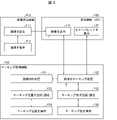
(ラベル付け装置の機能)
以上説明したラベル付け装置100と表示装置30の機能について、図面を参照して説明する。図5は、ラベル付け装置100と表示装置30の機能構成図である。図5に示すように、ラベル付け装置100は、画像読込機能F10とマーキング処理機能F20とを有する。表示装置30は、表示機能F30を有する。なお、図5に示した矢印は、主として信号又はデータの流れの方向を示したものであり、一方向性の矢印で示した部分においても、信号又はデータの双方向性を排除するものではない。
(Function of labeling device)
The functions of the labeling device 100 and the display device 30 described above will be described with reference to the drawings. FIG. 5 is a functional configuration diagram of the labeling device 100 and the display device 30. As shown in FIG. 5, the labeling device 100 has an image reading function F10 and a marking processing function F20. The display device 30 has a display function F30. The arrows shown in FIG. 5 mainly indicate the direction of the signal or data flow, and the portion indicated by the unidirectional arrow does not exclude the bidirectionality of the signal or data. ..
画像読込機能F10は、保存された対象画像を読み込み、第1表示部31に表示させる機能F11と、機能F11が読み込む対象画像を保存する機能F12である。換言すれば、機能F12は対象画像の格納先である。マーキング処理機能F20は、表示された対象画像を前処理する機能F21、対象画像又はカラーパレット上で選択された領域のマーキング処理を行う機能F22、対象画像上でマーキングされた画素の位置情報の記録及び読込を行う機能F23、機能23が記録及び読込を行う位置情報を保存する機能F24、カラーパレット上でマーキングされた画素の色情報の記録及び読込をする機能F25、及び機能25が記録及び読込を行う色情報を保存する機能F26である。換言すれば、機能F24は位置情報のデータベースであり、機能F26は色情報のデータベースである。表示機能F30は、対象画像を表示する機能F31と、カラーパレットを表示する機能F32である。
The image reading function F10 is a function F11 that reads a saved target image and displays it on the first display unit 31, and a function F12 that saves the target image read by the function F11. In other words, the function F12 is a storage destination of the target image. The marking processing function F20 includes a function F21 that preprocesses the displayed target image, a function F22 that performs marking processing of a selected area on the target image or a color palette, and recording of position information of pixels marked on the target image. And the function F23 for reading, the function F24 for storing the position information for recording and reading by the function 23, the function F25 for recording and reading the color information of the pixel marked on the color palette, and the function F25 for recording and reading. This is a function F26 for storing color information. In other words, the function F24 is a database of location information, and the function F26 is a database of color information. The display function F30 is a function F31 for displaying the target image and a function F32 for displaying the color palette.
対象画像を読み込み、第1表示部31に表示させる機能F11は対象画像取得部15および表示処理部11が有する。対象画像を保存する機能F12は画像保存部21が有する。対象画像を前処理する機能F21は、画像前処理部12が有する。マーキング処理を行う機能F22はマーキング処理部13が有する。画素の位置情報の記録及び読込を行う機能F23と画素の色情報の記録及び読込をする機能F25はマーキング記録部14が有する。位置情報を保存する機能F24と色情報を保存する機能F26は、マーキング記録保存部22が有する。対象画像を表示する機能F31は第1表示部31が有する。カラーパレットを表示する機能F32は第2表示部35が有する。
The target image acquisition unit 15 and the display processing unit 11 have a function F11 for reading the target image and displaying it on the first display unit 31. The image storage unit 21 has a function F12 for storing the target image. The image preprocessing unit 12 has a function F21 for preprocessing the target image. The marking processing unit 13 has a function F22 for performing marking processing. The marking recording unit 14 has a function F23 for recording and reading pixel position information and a function F25 for recording and reading pixel color information. The marking record storage unit 22 has a function F24 for storing position information and a function F26 for storing color information. The first display unit 31 has a function F31 for displaying a target image. The second display unit 35 has a function F32 for displaying a color palette.
以上のように、本例示的実施形態に係るラベル付け装置100においては、第1の表示領域に対象画像を表示し、第2の表示領域にカラーパレットを表示する表示処理部と、ユーザの入力に応じて対象画像上またはカラーパレット上の領域をマーキングするマーキング処理部と、を備え、マーキング処理部は、対象画像上においてユーザの入力に応じてマーキングした領域に含まれる色に対応するカラーパレット上の領域をマーキングし、カラーパレット上においてユーザの入力に応じてマーキングした領域に含まれる色に対応する対象画像上の領域をマーキングする、構成が採用されている。このため、本例示的実施形態に係るラベル付け装置100によれば、対象画像中の対象物の領域をユーザが効率的にラベル付けすることができる、という効果が得られる。
As described above, in the labeling device 100 according to the present exemplary embodiment, the display processing unit that displays the target image in the first display area and the color palette in the second display area, and the user's input. A marking processing unit for marking an area on the target image or a color palette according to the above is provided, and the marking processing unit is a color palette corresponding to a color included in the area marked on the target image according to a user's input. A configuration is adopted in which the upper area is marked and the area on the target image corresponding to the color included in the marked area according to the user's input is marked on the color palette. Therefore, according to the labeling device 100 according to the present exemplary embodiment, there is an effect that the user can efficiently label the area of the object in the target image.
(ラベル付け方法)
次に、ラベル付け方法M100の流れについて、図面を参照して説明する。図6は、例示的実施形態1に係るラベル付け装置100を用いるラベル付け方法M100(マーキング処理)の前処理フローチャートである。
(Labeling method)
Next, the flow of the labeling method M100 will be described with reference to the drawings. FIG. 6 is a preprocessing flowchart of the labeling method M100 (marking process) using the labeling device 100 according to the exemplary embodiment 1.
まず、対象画像取得部15は、1枚目の対象画像321を取得し、表示処理部11は、第1表示部31に、1枚目の対象画像321を表示させる。また、表示処理部11は、第2表示部35にカラーパレット36を表示させる(ステップS10)。次に、画像前処理部12は、対象画像321の前処理を実行するか否かを判定する(ステップS12)。前処理を行うか否かは、一連の対象画像32iの処理で共通とすることが好ましい。つまり、前処理する場合は、すべての対象画像32iを前処理する。前処理しない場合は、すべての対象画像32iを前処理しないことが好ましい。対象画像32iの前処理を実行するか否かは、予めユーザが指定してもよく、対象画像321においてユーザが指定してもよい。ステップS12において、前処理する場合(ステップS12:YES)は、マーキング処理はステップS14に移行して、画像前処理部12が対象画像321の前処理を行う。次いでマーキング処理は図7に示すステップS30に移行する。ステップS12において、前処理しない場合(ステップS12:NO)は、直接図7に示すステップS30に移行する。
First, the target image acquisition unit 15 acquires the first target image 321 and the display processing unit 11 causes the first display unit 31 to display the first target image 321. Further, the display processing unit 11 causes the second display unit 35 to display the color palette 36 (step S10). Next, the image preprocessing unit 12 determines whether or not to execute the preprocessing of the target image 321 (step S12). Whether or not to perform preprocessing is preferably common in the processing of a series of target images 32i. That is, when preprocessing, all target images 32i are preprocessed. When no preprocessing is performed, it is preferable not to preprocess all the target images 32i. Whether or not to execute the preprocessing of the target image 32i may be specified by the user in advance, or may be specified by the user in the target image 321. In the case of preprocessing in step S12 (step S12: YES), the marking process proceeds to step S14, and the image preprocessing unit 12 preprocesses the target image 321. Next, the marking process proceeds to step S30 shown in FIG. If no pretreatment is performed in step S12 (step S12: NO), the process directly proceeds to step S30 shown in FIG. 7.
図7は、1枚目の対象画像321のマーキング処理の図6に続くフローチャートである。図7のステップS30において、ユーザが対象画像321又はカラーパレット36にマーキングする。次に、ステップS32において、マーキング処理部13は、対象画像321にマーキングするか否かを判定する。具体的には、マーキング処理部13は、ユーザが、対象画像321にマーキングする操作を行ったか否かを判定する。対象画像321にマーキングする(ステップS32:YES)場合は、ステップS34に移行し、マーキング処理部13は、対象画像321でマーキングされた領域の画素の位置を抽出する。次に、ステップS36に移行し、マーキング記録部14は、抽出された画素の位置をマーキング記録保存部22に記録する。
FIG. 7 is a flowchart following FIG. 6 of the marking process of the first target image 321. In step S30 of FIG. 7, the user marks the target image 321 or the color palette 36. Next, in step S32, the marking processing unit 13 determines whether or not to mark the target image 321. Specifically, the marking processing unit 13 determines whether or not the user has performed an operation for marking the target image 321. When marking the target image 321 (step S32: YES), the process proceeds to step S34, and the marking processing unit 13 extracts the positions of the pixels in the region marked by the target image 321. Next, the process proceeds to step S36, and the marking recording unit 14 records the positions of the extracted pixels in the marking recording / storage unit 22.
次にステップS38に移行し、マーキング処理部13は、連動フラグがオンであるか否かを判定する。連動フラグとは、上述した双方向のマーキングの反映処理、すなわち、マーキング処理部13が、(i)対象画像321上においてユーザの入力に応じてマーキングした領域501に含まれる色に対応するカラーパレット36上の領域601をマーキングすること、および、(ii)カラーパレット36上においてユーザの入力に応じてマーキングした領域601に含まれる色に対応する対象画像321上の領域502をマーキングすることの一方または両方を制限するか否かを示すフラグである。このフラグは、例えば、ユーザがオン、オフ設定可能である。連動フラグがオンであれば、上述した双方向のマーキングの反映処理は制限されず、連動フラグがオフであれば、上述した双方向のマーキングの反映処理は制限される。連動フラグは例えばメモリ20に記録されている。
Next, the process proceeds to step S38, and the marking processing unit 13 determines whether or not the interlocking flag is on. The interlocking flag is the above-mentioned bidirectional marking reflection processing, that is, a color palette corresponding to the color included in the area 501 marked by the marking processing unit 13 in response to the user's input on the target image 321. One of marking the area 601 on the 36, and (ii) marking the area 502 on the target image 321 corresponding to the color included in the area 601 marked according to the user's input on the color palette 36. Or a flag indicating whether to limit both. This flag can be set on and off by the user, for example. If the interlocking flag is on, the bidirectional marking reflection process described above is not restricted, and if the interlocking flag is off, the bidirectional marking reflection process described above is restricted. The interlocking flag is recorded in, for example, the memory 20.
連動フラグがオンである(ステップS38:YES)場合は、ステップS40に移行し、マーキング処理部13は、抽出した画素の色をカラーパレット36にマーキングする。次にステップS42に移行し、マーキング記録部14は、マーキングした色をマーキング記録保存部22に記録する。マーキング記録保存部22に記録された色は、マーキング情報(以下、色のマーキング情報を「マーキング色」とも称する。)として保存される。次にマーキング処理はステップS54に移行する。なお、ステップS38において、連動フラグがオフである(ステップS38:NO)場合は、直接ステップS54に移行する。
When the interlocking flag is on (step S38: YES), the process proceeds to step S40, and the marking processing unit 13 marks the color of the extracted pixel on the color palette 36. Next, the process proceeds to step S42, and the marking recording unit 14 records the marked color in the marking recording storage unit 22. The color recorded in the marking record storage unit 22 is stored as marking information (hereinafter, the color marking information is also referred to as “marking color”). Next, the marking process proceeds to step S54. If the interlocking flag is off in step S38 (step S38: NO), the process directly proceeds to step S54.
一方、ステップS32において、ユーザがカラーパレット36にマーキングした(ステップS32:NO)場合は、ステップS44に移行し、マーキング処理部13は、カラーパレット36にマーキングされた画素の色を抽出する。次にステップS46に移行し、マーキング記録部14は、抽出された色をマーキング記録保存部22に記録する。
On the other hand, if the user marks the color palette 36 in step S32 (step S32: NO), the process proceeds to step S44, and the marking processing unit 13 extracts the color of the pixel marked on the color palette 36. Next, the process proceeds to step S46, and the marking recording unit 14 records the extracted color in the marking recording storage unit 22.
次にステップS48に移行し、マーキング処理部13は、連動フラグがオンであるか否かを判定する。連動フラグがオンである(ステップS48:YES)場合は、ステップS50に移行し、マーキング処理部13は、抽出した色を対象画像321にマーキングする。次にステップS52に移行し、マーキング記録部14は、対象画像321にマーキングした色の画素の位置をマーキング記録保存部22に記録する。次にマーキング処理はステップS54に移行する。なお、ステップS48において、連動フラグがオフである(ステップS48:NO)場合は、直接ステップS54に移行する。
Next, the process proceeds to step S48, and the marking processing unit 13 determines whether or not the interlocking flag is on. When the interlocking flag is on (step S48: YES), the process proceeds to step S50, and the marking processing unit 13 marks the extracted color on the target image 321. Next, the process proceeds to step S52, and the marking recording unit 14 records the positions of the pixels of the color marked on the target image 321 in the marking recording / storage unit 22. Next, the marking process proceeds to step S54. If the interlocking flag is off in step S48 (step S48: NO), the process directly proceeds to step S54.
ステップS54において、マーキング処理部13は、マーキングを続行するか否かを判定する。具体的には、同じ対象画像321においてユーザがマーキングする操作を行ったか否かを判定する。マーキングを続行する(ステップS54:YES)場合は、ステップS30に移行する。マーキングを続行しない(ステップS54:NO)場合は、1枚目の対象画像321のマーキング処理は終了する。マーキングが続行されない場合とは、例えばユーザが2枚目の対象画像322を選択して第1表示部31に表示させた場合等である。
In step S54, the marking processing unit 13 determines whether or not to continue marking. Specifically, it is determined whether or not the user has performed a marking operation on the same target image 321. If the marking is continued (step S54: YES), the process proceeds to step S30. If the marking is not continued (step S54: NO), the marking process of the first target image 321 ends. The case where the marking is not continued is, for example, a case where the user selects the second target image 322 and displays it on the first display unit 31.
次に、2枚目の対象画像322のマーキング処理について、図面を参照して説明する。以下の説明は、2枚目以降の対象画像32iのマーキング処理についても同様である。最初に図6に示すフローを行うことは1枚目のマーキング処理と同じである。図8は、2枚目以降の対象画像322のマーキング処理の、図6に続くフローチャートである。
Next, the marking process of the second target image 322 will be described with reference to the drawings. The following description is the same for the marking process of the second and subsequent target images 32i. Performing the flow shown in FIG. 6 first is the same as the marking process of the first sheet. FIG. 8 is a flowchart following FIG. 6 for marking processing of the second and subsequent target images 322.
図8のステップS60において、マーキング処理部13は、カラーパレット36にマーキング情報(マーキング色)を表示する。前述のように、マーキング情報は、マーキング記録保存部22に保存された色であり、ユーザが対象画像321においてマーキングした色である。次に、ステップS62において、マーキング処理部13は、マーキング情報を対象画像322に適用する(反映させる)か否かを判定する。具体的には、マーキング処理部13は、ユーザが、マーキング情報を対象画像322に適用する操作を行ったか否かを判定する。
In step S60 of FIG. 8, the marking processing unit 13 displays marking information (marking color) on the color palette 36. As described above, the marking information is a color stored in the marking record storage unit 22, and is a color marked by the user in the target image 321. Next, in step S62, the marking processing unit 13 determines whether or not the marking information is applied (reflected) to the target image 322. Specifically, the marking processing unit 13 determines whether or not the user has performed an operation of applying the marking information to the target image 322.
マーキング情報を対象画像322に適用する(ステップS62:YES)場合は、ステップS64に移行し、マーキング処理部13は、対象画像322にマーキング色を適用(マーキング)し、マーキング記録部14は、適用(マーキング)した色をマーキング記録保存部22に記録する。
When the marking information is applied to the target image 322 (step S62: YES), the process proceeds to step S64, the marking processing unit 13 applies the marking color to the target image 322 (marking), and the marking recording unit 14 applies the marking information. The (marked) color is recorded in the marking record storage unit 22.
ステップS64の次、又はステップS62において、マーキング情報を対象画像322に適用しない(ステップS62:NO)場合は、マーキング処理は、ステップS30に移行する。以下、図7で説明したステップS30からステップS54までと同じステップを実行する。ステップS30からステップS54までの説明は、図7で説明したとおりであるのでここでは省略する。
If the marking information is not applied to the target image 322 (step S62: NO) after step S64 or in step S62, the marking process shifts to step S30. Hereinafter, the same steps as those from step S30 to step S54 described with reference to FIG. 7 are executed. The description from step S30 to step S54 is as described with reference to FIG. 7, and is omitted here.
ステップS54において、マーキングを続行しない(ステップS54:NO)場合は、ステップS66に移行し、次の対象画像をマーキングするか否かを判定する。次の対象画像をマーキングする、つまりユーザが次の対象画像を選択した(ステップS66:YES)場合は、図6のステップS10に移行し、図6と図8のステップを繰り返す。ユーザが次の対象画像をマーキングしないまま終了条件を満たした(ステップS66:NO)場合は、マーキング処理は終了する。終了条件を満たした場合とは、ユーザがマーキング処理の終了を選択した場合、又は電源オフの場合等である。なお、ステップS54において、マーキングを続行する(ステップS54:YES)場合は、ステップS62に移行する。
If the marking is not continued in step S54 (step S54: NO), the process proceeds to step S66, and it is determined whether or not to mark the next target image. When the next target image is marked, that is, when the user selects the next target image (step S66: YES), the process proceeds to step S10 of FIG. 6, and the steps of FIGS. 6 and 8 are repeated. If the user satisfies the end condition without marking the next target image (step S66: NO), the marking process ends. The case where the end condition is satisfied is the case where the user selects the end of the marking process, the case where the power is turned off, or the like. If the marking is continued in step S54 (step S54: YES), the process proceeds to step S62.
以上のマーキング処理を多くの対象画像32iについて繰り返すと、マーキング情報がマーキング記録保存部22に蓄積されていく。マーキング情報の蓄積量が十分に大きくなると、第2の対象画像32iに対してユーザが自らマーキングする必要はない。代わりに、第2の対象画像32iにユーザがマーキング情報を適用することにより、対象物の領域にマーキングがなされた対象画像32iが作成される。
When the above marking process is repeated for many target images 32i, marking information is accumulated in the marking record storage unit 22. When the accumulated amount of marking information becomes sufficiently large, the user does not need to mark the second target image 32i by himself / herself. Instead, the user applies the marking information to the second target image 32i to create the target image 32i in which the area of the object is marked.
マーキング記録保存部22は、過去にマーキング処理部13がマーキングしたカラーパレット36上の領域に含まれる色を任意の識別情報に関連付けて保存することができる。例えば、マーキング記録保存部22は、過去にマーキング処理部13がマーキングしたカラーパレット36上の領域に含まれる色に、特定の名前を付けて保存することができる。マーキング処理部13は、対象画像取得部15が取得した第2の対象画像に対し、マーキング記録保存部22が特定の名前(識別情報)に関連付けて保存している色に対応する領域をマーキングしてもよい。これにより、蓄積した過去のマーキング色に任意の識別情報を関連付けて保存し、そのうち特定の識別情報に関連付けて保存したマーキング色を利用して第2の対象画像のマーキングを行うことができる。これにより、適切なマーキング色を適用することができる。また、例えば、複数種類のマーキングを並行して行うことができる。
The marking record storage unit 22 can store the colors included in the area on the color palette 36 marked by the marking processing unit 13 in the past in association with arbitrary identification information. For example, the marking record storage unit 22 can give a specific name to a color included in the area on the color palette 36 marked by the marking processing unit 13 in the past and store the color. The marking processing unit 13 marks an area corresponding to the color stored in association with a specific name (identification information) on the second target image acquired by the target image acquisition unit 15. You may. Thereby, any identification information can be associated with the accumulated past marking color and stored, and the marking color saved in association with the specific identification information can be used to mark the second target image. This makes it possible to apply an appropriate marking color. Further, for example, a plurality of types of markings can be performed in parallel.
以上のように、本例示的実施形態に係るラベル付け方法M100においては、第1の表示領域に対象画像を表示し、第2の表示領域にカラーパレットを表示し、ユーザの入力に応じて対象画像上またはカラーパレット上の領域をマーキングし、このマーキングは、対象画像上においてユーザの入力に応じてマーキングした領域に含まれる色に対応するカラーパレット上の領域をマーキングし、カラーパレット上においてユーザの入力に応じてマーキングした領域に含まれる色に対応する対象画像上の領域をマーキングする、構成が採用されている。このため、本例示的実施形態に係るラベル付け方法M100によれば、対象画像中の対象物の領域をユーザが効率的にラベル付けすることができる、という効果が得られる。
As described above, in the labeling method M100 according to the present exemplary embodiment, the target image is displayed in the first display area, the color palette is displayed in the second display area, and the target is input according to the user's input. Marking an area on the image or color palette, this marking marks the area on the color palette corresponding to the color contained in the area marked on the target image in response to user input, and the user on the color palette. A configuration is adopted in which the area on the target image corresponding to the color included in the marked area is marked according to the input of. Therefore, according to the labeling method M100 according to the present exemplary embodiment, there is an effect that the user can efficiently label the area of the object in the target image.
〔実施形態2〕
次に、本発明の第2の例示的実施形態に係るラベル付け装置200について、図面を参照して説明する。なお、例示的実施形態1にて説明した構成要素と同じ機能を有する構成要素については、同じ符号を付し、その説明を適宜省略する。ラベル付け装置200の構成は、図9に示すように、ラベル付け装置100と基本的に同じであり、ラベル付け装置100と異なる点は、制御部10に対象範囲特定部16を備える点である。
[Embodiment 2]
Next, the labeling device 200 according to the second exemplary embodiment of the present invention will be described with reference to the drawings. The components having the same functions as those described in the first embodiment are designated by the same reference numerals, and the description thereof will be omitted as appropriate. As shown in FIG. 9, the configuration of the labeling device 200 is basically the same as that of the labeling device 100, and the difference from the labeling device 100 is that the control unit 10 includes the target range specifying unit 16. ..
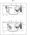
対象範囲特定部16は、対象画像から、対象範囲を特定する。図10は、例示的実施形態2に係るラベル付け装置200を用いて対象画像321,322の対象物の領域をマーキングする様子を示す概念図である。対象範囲特定部16は、図10(a)に示すように、対象画像321から、赤錆が発生している物体(パラボラアンテナ)の範囲を対象範囲40として抽出する。また、対象範囲特定部16は、図10(b)に示すように、対象画像322から、赤錆が発生している物体(錠前)の範囲を対象範囲42として抽出する。対象範囲特定部16は、ユーザの座標入力に応じて対象範囲を特定してもよい。また、対象範囲特定部16は、例えば、予め特定の物体(パラボラアンテナ、錠前等)を検出するように学習された学習済モデルやパターンマッチング等の物体検出アルゴリズムを用いて、対象画像から特定の物体を検出し、その結果に応じて対象範囲を特定してもよい。例えば、対象範囲特定部16は、特定の物体(パラボラアンテナ、錠前等)が検出された領域を含む矩形領域を対象範囲として特定してもよい。また、対象範囲特定部16は、例えばユーザが入力した対象(鉄、金属等)又は色(赤茶色等)の条件に応じて、対象範囲を抽出してもよい。これにより、表示処理部11は、対象範囲特定部16により抽出乃至特定された対象範囲を表示することができる。
The target range specifying unit 16 specifies the target range from the target image. FIG. 10 is a conceptual diagram showing how the labeling device 200 according to the second embodiment is used to mark the area of the object of the target images 321 and 322. As shown in FIG. 10A, the target range specifying unit 16 extracts the range of the object (parabolic antenna) in which red rust is generated from the target image 321 as the target range 40. Further, as shown in FIG. 10B, the target range specifying unit 16 extracts the range of the object (lock) in which red rust is generated from the target image 322 as the target range 42. The target range specifying unit 16 may specify the target range according to the coordinate input of the user. Further, the target range specifying unit 16 is specified from the target image by using, for example, a trained model trained in advance to detect a specific object (parabola antenna, lock, etc.) or an object detection algorithm such as pattern matching. An object may be detected and a target range may be specified according to the result. For example, the target range specifying unit 16 may specify a rectangular region including a region in which a specific object (parabolic antenna, lock, etc.) is detected as the target range. Further, the target range specifying unit 16 may extract the target range according to the conditions of the target (iron, metal, etc.) or the color (reddish brown, etc.) input by the user, for example. As a result, the display processing unit 11 can display the target range extracted or specified by the target range specifying unit 16.
さらに、本例示的実施形態では、表示処理部11は、対象範囲特定部16が特定した対象範囲に含まれる色からカラーパレットを構成する。具体的には、表示処理部11は、抽出された対象範囲40に含まれる色を用いてカラーパレット38を生成する。また、表示処理部11は、抽出された対象範囲42に含まれる色を用いてカラーパレット39を生成する。
Further, in the present exemplary embodiment, the display processing unit 11 constitutes a color palette from the colors included in the target range specified by the target range specifying unit 16. Specifically, the display processing unit 11 generates a color palette 38 using the colors included in the extracted target range 40. Further, the display processing unit 11 generates a color palette 39 using the colors included in the extracted target range 42.
また、その後のマーキング処理では、マーキング処理部13は、当該対象範囲内の領域のみをマーキングする。これにより、カラーパレット上においてユーザの入力に応じてマーキングした領域に含まれる色に対応する領域が、対象領域外に存在していた(例えば、偶々背景に錆と同じ色の部分が存在した)場合であっても、マーキング処理部13が不適切な領域をマーキングすることを防ぐことができる。
Further, in the subsequent marking process, the marking process unit 13 marks only the area within the target range. As a result, the area corresponding to the color included in the area marked according to the user's input on the color palette existed outside the target area (for example, a part having the same color as rust happened to exist in the background). Even in this case, it is possible to prevent the marking processing unit 13 from marking an inappropriate area.
次に、例示的実施形態2に係るラベル付け方法M200の流れについて、図面を参照して説明する。図11は、例示的実施形態2に係るラベル付け装置200を用いるマーキング処理の前処理フローチャートである。図11に示すラベル付け方法M200のステップS10からステップS14までは、図6に示すラベル付け方法M100に係るステップS10からステップS14までの前処理フローと同じであるので、その説明は省略する。
Next, the flow of the labeling method M200 according to the exemplary embodiment 2 will be described with reference to the drawings. FIG. 11 is a preprocessing flowchart of the marking process using the labeling device 200 according to the second embodiment. Since steps S10 to S14 of the labeling method M200 shown in FIG. 11 are the same as the pretreatment flow from step S10 to step S14 according to the labeling method M100 shown in FIG. 6, the description thereof will be omitted.
ステップS16において、マーキング処理部13は、対象範囲特定部16が対象画像から対象範囲を特定したか否かを判定する。対象範囲特定部16が対象画像から対象範囲を特定した(ステップS16:YES)場合は、前処理フローはステップS18に移行する。ステップS18において、表示処理部11は、対象範囲に含まれる色種でカラーパレット38を作成して表示する。対象範囲特定部16が対象画像から対象範囲を特定しない場合(ステップS16:NO)は、前処理フローはステップS20に移行する。ステップS20において、表示処理部11は、対象画像全体に含まれる色種でカラーパレット36を作成して表示する。次いで、1枚目の対象画像を処理する場合は図7に示すステップS30に、2枚目以降の対象画像を処理している場合は図8に示すステップS30に、それぞれ移行する。以降のステップは、マーキング処理部13が、当該対象範囲内の領域のみをマーキングすることを除き、図7又は図8で説明したとおりである。
In step S16, the marking processing unit 13 determines whether or not the target range specifying unit 16 has specified the target range from the target image. When the target range specifying unit 16 specifies the target range from the target image (step S16: YES), the preprocessing flow shifts to step S18. In step S18, the display processing unit 11 creates and displays the color palette 38 with the color types included in the target range. When the target range specifying unit 16 does not specify the target range from the target image (step S16: NO), the preprocessing flow shifts to step S20. In step S20, the display processing unit 11 creates and displays the color palette 36 with the color types included in the entire target image. Next, when processing the first target image, the process proceeds to step S30 shown in FIG. 7, and when processing the second and subsequent target images, the process proceeds to step S30 shown in FIG. Subsequent steps are as described with reference to FIG. 7 or 8 except that the marking processing unit 13 marks only the area within the target range.
以上のように、対象画像から対象範囲を設定することにより、対象範囲に含まれる色種を絞り込むことができる。そのため、細かい色のグラディエーションを持つカラーパレットを生成することができる。このカラーパレットを用いてマーキングすることにより、詳細な色の境界を規定したマーキング情報を蓄積することができる。そのため、例示的実施形態1に係る効果に加えて、対象物の領域のラベル付けを精度よく行うことができるという効果が得られる。
As described above, by setting the target range from the target image, the color types included in the target range can be narrowed down. Therefore, it is possible to generate a color palette with fine color gradation. By marking using this color palette, it is possible to accumulate marking information that defines detailed color boundaries. Therefore, in addition to the effect according to the exemplary embodiment 1, the effect that the area of the object can be labeled with high accuracy can be obtained.
なお、異なる対象画像で異なる対象範囲を設定してカラーパレットを作成すると、対象画像ごとにカラーパレットが作成される。しかし、個々のカラーパレットに記録されたマーキング情報は、全色を含む1つのカラーパレット(標準カラーパレット)に表示することができる。そのため、標準カラーパレットに表示されたすべてのマーキング情報を第2の対象画像に適用してマーキングすることにより、ユーザはラベル付け作業を容易に実行することができる。
If you create a color palette by setting different target ranges for different target images, a color palette will be created for each target image. However, the marking information recorded in each color palette can be displayed in one color palette (standard color palette) including all colors. Therefore, by applying all the marking information displayed on the standard color palette to the second target image for marking, the user can easily perform the labeling operation.
また、上述したように、マーキング処理において、マーキング処理部13が、対象範囲内の領域のみをマーキングし、対象範囲外の領域をマーキングしないようにすることにより、カラーパレット上においてユーザの入力に応じてマーキングした領域に含まれる色に対応する領域が、対象領域外に存在していた場合であっても、マーキング処理部13が不適切な領域をマーキングすることを防ぐことができる。
Further, as described above, in the marking process, the marking processing unit 13 marks only the area within the target range and does not mark the area outside the target range, so that the marking process responds to the user's input on the color palette. Even when the area corresponding to the color included in the marked area exists outside the target area, it is possible to prevent the marking processing unit 13 from marking an inappropriate area.
〔変形例〕
(変形例1:編集機能)
変形例として、ラベル付け装置100,200が備えていてもよい機能について、以下に説明する。ラベル付け装置100,200は、マーキングした領域を編集可能であってもよい。編集は、ユーザが行ってもよく、マーキング処理部が行ってもよい。図12は、本発明の他の例示的実施形態に係るラベル付け装置の編集機能を示す図である。
[Modification example]
(Transformation example 1: Editing function)
As a modification, the functions that the labeling devices 100 and 200 may have will be described below. Labeling devices 100, 200 may be able to edit the marked area. Editing may be performed by the user or by the marking processing unit. FIG. 12 is a diagram showing an editing function of a labeling device according to another exemplary embodiment of the present invention.
例えば、対象画像321においてユーザは連続した領域をマーキングする。連続した錆の領域に含まれる色は色相又は彩度が緩やかに変化している。そして、カラーパレット36もグラディエーションを有する色相環であるため、ユーザが対象画像321においてマーキングした色の領域がカラーパレット36にマーキングされた場合も、ある程度の連続した領域となる。しかし、例えば、図12(a)に示すように、対象画像321においてユーザがマーキングした領域501中に、錆ではない領域の色(錆とは色相の異なる色)、つまりノイズが混じっている場合がある。ノイズは、カラーパレット36では飛び地の領域601a、601bとしてマーキングされる。
For example, in the target image 321 the user marks a continuous area. The hue or saturation of the color contained in the continuous rust area changes slowly. Since the color palette 36 is also a color wheel having gradation, even when the color region marked by the user in the target image 321 is marked on the color palette 36, it becomes a continuous region to some extent. However, for example, as shown in FIG. 12A, when the region 501 marked by the user in the target image 321 contains a color of a region that is not rust (a color having a hue different from that of rust), that is, noise. There is. The noise is marked as enlave areas 601a, 601b on the color palette 36.
このような場合、ユーザはマーキングされた領域601a、601bを削除することができる。具体的には、ユーザは、カラーパレット36上での飛び地である領域601a、601bを選択し、削除ボタンを押す。これにより、図12(b)に示すように、領域601は残して領域601a、601bのみを削除することができる。
In such a case, the user can delete the marked areas 601a and 601b. Specifically, the user selects the areas 601a and 601b that are the excursions on the color palette 36, and presses the delete button. As a result, as shown in FIG. 12B, only the regions 601a and 601b can be deleted while leaving the region 601.
また、ユーザの指示がなくとも、マーキング処理部13が所定の条件を満たす飛び地を削除するように設定してもよい。所定の条件とは、面積が所定値以下であること、又は、飛び地の位置が、メインの領域601から所定の距離以上に離れていること、等である。
Further, the marking processing unit 13 may be set to delete the excursion satisfying a predetermined condition without the instruction of the user. The predetermined conditions are that the area is equal to or less than a predetermined value, or that the position of the excursion is separated from the main area 601 by a predetermined distance or more.
また、例えば対象画像321上にマーキングした複数の領域は、カラーパレット36上で複数の領域としてマーキングされる。ユーザは、カラーパレット36上における複数の領域のそれぞれが広い錆領域の一部であると判断した場合は、これらの複数の領域を統合する編集をしてもよい。マーキング処理部13は、ユーザの指示を受けて、複数の領域を合わせて1つの領域に統合する。これにより、錆画像と考えられる領域を漏れなくカラーパレット36上でマーキングすることができる。領域を統合する場合は、統合した領域の輪郭が滑らかになるように統合処理することが好ましい。
Further, for example, a plurality of regions marked on the target image 321 are marked as a plurality of regions on the color palette 36. If the user determines that each of the plurality of regions on the color palette 36 is a part of a wide rust region, the user may edit to integrate the plurality of regions. The marking processing unit 13 receives a user's instruction and integrates a plurality of areas into one area. As a result, the area considered to be a rust image can be marked on the color palette 36 without omission. When integrating regions, it is preferable to perform integration processing so that the contour of the integrated region becomes smooth.
また、カラーパレット36上でマーキングされた領域を対象画像321上にマーキングした際に、明らかに対象物の領域ではない部分にマーキングされた場合は、その領域のマーキングのみを削除することができる。これにより、誤った領域になされたマーキングを除去することができる。
Further, when the area marked on the color palette 36 is marked on the target image 321 and the area is clearly not the area of the object, only the marking of that area can be deleted. This makes it possible to remove markings made in the wrong area.
以上の機能を備えることにより、対象物の領域ではないと考えられるカラーパレット上のマーキング領域、又は対象物の領域ではない対象画像上のマーキング領域を削除することができる。また、カラーパレット上で、複数の領域を連続した領域に統合することができる。なお、一方の画面で編集した結果を他方の画面に反映させないように設定してもよい。
By providing the above functions, it is possible to delete the marking area on the color palette that is not considered to be the area of the object, or the marking area on the target image that is not the area of the object. In addition, a plurality of areas can be integrated into a continuous area on the color palette. It should be noted that the result edited on one screen may be set so as not to be reflected on the other screen.
(変形例2:重み付け機能)
マーキング処理部13は、マーキング記録保存部22が保存している色の重み付けを行い、当該重み付けに基づいて第2の対象画像上の領域をマーキングする機能を有していてもよい。
(Modification 2: Weighting function)
The marking processing unit 13 may have a function of weighting the colors stored in the marking record storage unit 22 and marking an area on the second target image based on the weighting.
重み付けの方法としては、例えば、カラーパレット上でマーキングされた色の回数を重み付けの指標とすることができる。色の画素ごとにマーキングされた回数を複数の対象画像で合計した場合、数多くマーキングされた色ほどユーザが求める対象物の領域を示す色である確率が高い。逆に、マーキングされた回数が少ない色は、ノイズであると判断することができる。そこで、マーキング処理部13は、マーキング記録保存部22が保存している色を、マーキングされた回数に基づいて重み付けする。例えば、マーキング処理部13は、ある回数を閾値として設定し、マーキング記録保存部22が保存している色のうち、閾値以上マーキングされた色を特定する。そして、マーキング処理部13は、第2の対象画像にラベル付けをする場合に、閾値以上マーキングされた色として特定した色に対応する領域をマーキングすることで、精度の高いマーキングを行うことができる。なお、重み付けは、回数に基づく方法に限定されない。
As a weighting method, for example, the number of times of the color marked on the color palette can be used as a weighting index. When the number of markings for each color pixel is totaled for a plurality of target images, the more marked colors, the higher the probability that the color indicates the area of the object desired by the user. On the contrary, a color with a small number of markings can be determined to be noise. Therefore, the marking processing unit 13 weights the colors stored by the marking record storage unit 22 based on the number of markings. For example, the marking processing unit 13 sets a certain number of times as a threshold value, and among the colors stored by the marking record storage unit 22, a color marked with a threshold value or more is specified. Then, when labeling the second target image, the marking processing unit 13 can perform marking with high accuracy by marking the area corresponding to the color specified as the color marked above the threshold value. .. The weighting is not limited to the method based on the number of times.
また、表示処理部11は、重み付けされた色を、その重みに基づいて、ランキング形式又は上位数個の色のみ表示するようにしてもよい。
Further, the display processing unit 11 may display only the weighted colors in the ranking format or the top several colors based on the weights.
(変形例3:一括マーキング機能)
マーキング処理部13は、まだラベル付けしていない対象画像に対して、一括してラベル付けをする機能を有していてもよい。多数の対象画像にマーキング処理を施し、マーキング情報が蓄積されてくると、それ以降はユーザが第2の対象画像にマーキング処理を施す必要がなくなる。その場合、マーキング処理部13は、ユーザが一括して指定した複数の対象画像を順次マーキングをする機能を有していてもよい。このような構成により、ユーザが1枚ずつマーキング情報を用いてマーキングする必要がなくなり、ラベル付け作業の効率化を図ることができる。
(Modification example 3: Batch marking function)
The marking processing unit 13 may have a function of collectively labeling target images that have not been labeled yet. When a large number of target images are marked and the marking information is accumulated, the user does not need to perform the marking process on the second target image thereafter. In that case, the marking processing unit 13 may have a function of sequentially marking a plurality of target images collectively designated by the user. With such a configuration, it is not necessary for the user to mark one sheet at a time using the marking information, and the efficiency of the labeling work can be improved.
すなわち、対象画像取得部15は、複数の第2の対象画像を取得し、マーキング処理部13は、対象画像取得部15が取得した複数の第2の対象画像に対し、マーキング記録保存部22が保存している色に対応する領域をマーキングするように構成されていてもよい。
That is, the target image acquisition unit 15 acquires a plurality of second target images, and the marking processing unit 13 has a marking record storage unit 22 for the plurality of second target images acquired by the target image acquisition unit 15. It may be configured to mark the area corresponding to the stored color.
(変形例4:カラーパレットの表示形式)
表示処理部11は、カラーパレットの表示形式を選択して表示する機能を有していてもよい。上述の例示的実施形態1及び例示的実施形態2では、カラーパレットは、Lab色空間を例示している。しかし、カラーパレットの表示形式はこれに限られない。図13は、他の例示的実施形態に係るカラーパレットの表示図である。図13に示すように、例えば横方向に色相を、縦方向に彩度をそれぞれ配列した形式でもよい。このように、色相、彩度、明度の中から選択した2つ以上の要素に基づいて配列した任意の表示形式を用意しておくことができる。そして、複数の表示形式の中から選択できるように構成することで、ユーザが対象物の領域をマーキングし易い表示形式を選択することができる。
(Transformation example 4: Color palette display format)
The display processing unit 11 may have a function of selecting and displaying a display format of the color palette. In the above-mentioned exemplary embodiment 1 and exemplary embodiment 2, the color palette illustrates the Lab color space. However, the display format of the color palette is not limited to this. FIG. 13 is a display diagram of a color palette according to another exemplary embodiment. As shown in FIG. 13, for example, the hue may be arranged in the horizontal direction and the saturation may be arranged in the vertical direction. In this way, it is possible to prepare an arbitrary display format arranged based on two or more elements selected from hue, saturation, and lightness. Then, by configuring the display format so that it can be selected from a plurality of display formats, it is possible to select a display format in which the user can easily mark the area of the object.
〔実施形態3〕
本発明の他の実施形態について、以下に説明する。なお、説明の便宜上、上記実施形態にて説明した部材と同じ機能を有する部材については、同じ符号を付記する。
[Embodiment 3]
Other embodiments of the present invention will be described below. For convenience of explanation, the same reference numerals are given to the members having the same functions as the members described in the above-described embodiment.
(ラベル付け装置)
図15は、本実施形態に係るラベル付け装置100の構成を示すブロック図である。図15に示すように、ラベル付け装置100は、表示処理部11およびマーキング処理部13を備えている。
(Labeling device)
FIG. 15 is a block diagram showing the configuration of the labeling device 100 according to the present embodiment. As shown in FIG. 15, the labeling device 100 includes a display processing unit 11 and a marking processing unit 13.
表示処理部11は、第1の表示領域に対象画像を表示し、第2の表示領域にカラーパレットを表示する。マーキング処理部13は、ユーザの入力に応じて対象画像上およびカラーパレット上の領域をマーキングする。さらに、マーキング処理部13は、対象画像上においてユーザの入力に応じてマーキングした領域に含まれる色に対応するカラーパレット上の領域をマーキングし、カラーパレット上において前記ユーザの入力に応じてマーキングした領域に含まれる色に対応する対象画像上の領域をマーキングする。
The display processing unit 11 displays the target image in the first display area and displays the color palette in the second display area. The marking processing unit 13 marks areas on the target image and on the color palette according to the input of the user. Further, the marking processing unit 13 marks an area on the color palette corresponding to the color included in the area marked according to the user's input on the target image, and marks the area on the color palette according to the user's input. Mark the area on the target image that corresponds to the color contained in the area.
上記の構成によれば、マーキング処理部13は、ユーザの入力に応じた対象画像上のマーキングの結果をカラーパレット上にも反映することができるとともに、ユーザの入力に応じたカラーパレット上のマーキングの結果を対象画像上にも反映することができる。すなわち、マーキング処理部13は、ユーザの入力に応じた対象画像上およびカラーパレット上の領域のマーキングを双方向に反映させることができる。これにより、画像中の対象物の領域をユーザが効率的にラベル付けすることができる。
According to the above configuration, the marking processing unit 13 can reflect the result of marking on the target image according to the user's input on the color palette, and the marking on the color palette according to the user's input. The result of can be reflected on the target image. That is, the marking processing unit 13 can reflect the marking of the area on the target image and the color palette according to the input of the user in both directions. This allows the user to efficiently label the area of the object in the image.
(ラベル付け方法)
次に、ラベル付け方法M100の流れについて、図面を参照して説明する。図16は、例示的実施形態3に係るラベル付け装置100を用いるラベル付け方法M100(マーキング処理)のフローチャートである。
(Labeling method)
Next, the flow of the labeling method M100 will be described with reference to the drawings. FIG. 16 is a flowchart of a labeling method M100 (marking process) using the labeling device 100 according to the third embodiment.
まず、表示処理部11によって、第1の表示領域に対象画像を表示し、第2の表示領域にカラーパレットを表示する(ステップS10)。
続いて、マーキング処理部13によって、ユーザの入力に応じて対象画像上またはカラーパレット上の領域をマーキングする(ステップ30)。次に、ステップS32において、マーキング処理部13は、ユーザが対象画像にマーキングしたか否かを判定する。ユーザが対象画像にマーキングした(ステップS32:YES)場合は、ステップS34に移行し、マーキング処理部13は、対象画像でマーキングされた領域の画素の位置を抽出する。次に、ステップS40において、マーキング処理部13は、抽出した画素の色をカラーパレット36にマーキングする。その後、ステップS54に移行する。
First, the display processing unit 11 displays the target image in the first display area and displays the color palette in the second display area (step S10).
Subsequently, the marking processing unit 13 marks an area on the target image or the color palette according to the input of the user (step 30). Next, in step S32, the marking processing unit 13 determines whether or not the user has marked the target image. When the user has marked the target image (step S32: YES), the process proceeds to step S34, and the marking processing unit 13 extracts the positions of the pixels in the area marked by the target image. Next, in step S40, the marking processing unit 13 marks the color of the extracted pixel on the color palette 36. After that, the process proceeds to step S54.
一方、ステップS32において、ユーザがカラーパレット36にマーキングした(ステップS32:NO)場合は、ステップS44に移行し、マーキング処理部13は、カラーパレット36にマーキングされた画素の色を抽出する。次に、ステップS50において、マーキング処理部13は、抽出した色を対象画像にマーキングする。その後、ステップS54に移行する。
On the other hand, if the user marks the color palette 36 in step S32 (step S32: NO), the process proceeds to step S44, and the marking processing unit 13 extracts the color of the pixel marked on the color palette 36. Next, in step S50, the marking processing unit 13 marks the extracted color on the target image. After that, the process proceeds to step S54.
ステップS54において、マーキング処理部13は、マーキングが続行されたか否か、つまり、同じ対象画像においてユーザによるマーキングが行われたか否かを判定する。マーキングが続行された(ステップS54:YES)場合は、ステップS30に移行する。マーキングが続行されない(ステップS54:NO)場合は、対象画像のマーキング処理は終了する。
In step S54, the marking processing unit 13 determines whether or not the marking is continued, that is, whether or not the marking is performed by the user in the same target image. If the marking is continued (step S54: YES), the process proceeds to step S30. If the marking is not continued (step S54: NO), the marking process of the target image ends.
以上の方法により、ユーザの入力に応じた対象画像上およびカラーパレット上の領域のマーキングを双方向に反映させることができ、画像中の対象物の領域をユーザが効率的にラベル付けすることができる。
By the above method, the marking of the area on the target image and the color palette according to the input of the user can be reflected in both directions, and the user can efficiently label the area of the object in the image. can.
〔ソフトウェアによる実現例〕
制御部10の各部は、集積回路(ICチップ)等に形成された論理回路(ハードウェア)によって実現してもよいし、ソフトウェアによって実現してもよい。
[Example of implementation by software]
Each part of the control unit 10 may be realized by a logic circuit (hardware) formed in an integrated circuit (IC chip) or the like, or may be realized by software.
後者の場合、図14に示すように、制御部10は、各機能を実現するソフトウェアであるプログラムPの命令を実行するコンピュータCを備えている。このコンピュータCは、例えば少なくとも1つのプロセッサ(制御装置)C1を備えていると共に、上記プログラムPを記憶したコンピュータ読み取り可能な少なくとも1つの記録媒体Mを備えている。そして、上記コンピュータCにおいて、上記プロセッサC1が上記プログラムPを上記記録媒体Mから読み取ってメモリC2に保存し、これを実行することにより、本発明の目的が達成される。上記プロセッサC1としては、例えばCPUを用いることができる。上記記録媒体Mとしては、「一時的でない有形の媒体」、例えば、ROM等の他、テープ、ディスク、カード、半導体メモリ、プログラマブルな論理回路などを用いることができる。また、上記プログラムPを展開するRAMなどをさらに備えていてもよい。また、上記プログラムPは、該プログラムPを伝送可能な任意の伝送媒体(通信ネットワークや放送波等)を介して上記コンピュータCに供給されてもよい。なお、本発明の一態様は、上記プログラムPが電子的な伝送によって具現化された、搬送波に埋め込まれたデータ信号の形態でも実現され得る。
In the latter case, as shown in FIG. 14, the control unit 10 includes a computer C that executes an instruction of the program P, which is software that realizes each function. The computer C includes, for example, at least one processor (control device) C1 and at least one computer-readable recording medium M that stores the program P. Then, in the computer C, the processor C1 reads the program P from the recording medium M, stores the program P in the memory C2, and executes the program, thereby achieving the object of the present invention. As the processor C1, for example, a CPU can be used. As the recording medium M, a “non-temporary tangible medium” such as a ROM, a tape, a disk, a card, a semiconductor memory, a programmable logic circuit, or the like can be used. Further, a RAM or the like for expanding the program P may be further provided. Further, the program P may be supplied to the computer C via an arbitrary transmission medium (communication network, broadcast wave, etc.) capable of transmitting the program P. It should be noted that one aspect of the present invention can also be realized in the form of a data signal embedded in a carrier wave, in which the program P is embodied by electronic transmission.
〔付記事項1〕
本発明は、上述した例示的実施形態に限定されるものでなく、請求項に示した範囲で種々の変更が可能である。例えば、上述した例示的実施形態に開示された技術的手段を適宜組み合わせて得られる例示的実施形態についても、本発明の技術的範囲に含まれる。
[Appendix 1]
The present invention is not limited to the above-mentioned exemplary embodiments, and various modifications can be made within the scope of the claims. For example, an exemplary embodiment obtained by appropriately combining the technical means disclosed in the above-mentioned exemplary embodiments is also included in the technical scope of the present invention.
〔付記事項2〕
上述した例示的実施形態の一部又は全部は、以下のようにも記載され得る。ただし、本発明は、以下の記載する態様に限定されるものではない。
[Appendix 2]
Some or all of the exemplary embodiments described above may also be described as follows. However, the present invention is not limited to the aspects described below.
態様1に係るラベル付け装置は、第1の対象画像と、カラーパレットとを表示する表示処理部と、ユーザの入力に応じて前記第1の対象画像上または前記カラーパレット上の領域をマーキングするマーキング処理部と、を備え、前記マーキング処理部は、前記第1の対象画像上の領域又は前記カラーパレット上の領域の一方に関する前記ユーザの入力に応じて、他方の領域をマーキングする。
The labeling device according to the first aspect has a display processing unit that displays a first target image and a color palette, and marks an area on the first target image or the color palette according to user input. A marking processing unit is provided, and the marking processing unit marks the other area in response to the user's input regarding one of the area on the first target image or the area on the color palette.
上記の構成によれば、ユーザの入力に応じた対象画像上又はカラーパレット上の領域の一方のマーキングを他方の領域に反映させることができる。これにより、画像中の対象物の領域をユーザが効率的にラベル付けすることができる。
According to the above configuration, one marking of the area on the target image or the color palette according to the input of the user can be reflected in the other area. This allows the user to efficiently label the area of the object in the image.
態様2に係るラベル付け装置においては、態様1に係る構成に加えて、前記マーキング処理部は、第2の対象画像に対し、過去に前記マーキング処理部がマーキングした前記カラーパレット上の領域に含まれる色に対応する領域をマーキングする、という構成が採用されている。
In the labeling device according to the second aspect, in addition to the configuration according to the first aspect, the marking processing unit is included in the area on the color palette previously marked by the marking processing unit with respect to the second target image. A configuration is adopted in which the area corresponding to the color to be labeled is marked.
上記の構成によれば、蓄積した過去のマーキング色を利用して第2の対象画像のマーキングを行うことができる。これにより、マーキング色が蓄積していくほどに、汎化性能が上がっていき、マーキングの精度の向上、ラベル付け作業時間の短縮、および、マーキング色の修正時間の短縮を実現することができる。
According to the above configuration, the second target image can be marked by using the accumulated past marking colors. As a result, as the marking colors are accumulated, the generalization performance is improved, and it is possible to improve the marking accuracy, shorten the labeling work time, and shorten the marking color correction time.
態様3に係るラベル付け装置においては、態様2に係る構成に加えて、過去に前記マーキング処理部がマーキングした前記カラーパレット上の領域に含まれる色を蓄積して保存するマーキング記録保存部を更に備える、という構成が採用されている。
In the labeling device according to the third aspect, in addition to the configuration according to the second aspect, a marking record storage unit that accumulates and stores the colors contained in the area on the color palette previously marked by the marking processing unit is further provided. The configuration of preparing is adopted.
上記の構成によれば、蓄積した過去のマーキング色のデータを保存しておくことができるため、第2の対象画像のマーキングを容易に行うことができる。
According to the above configuration, since the accumulated past marking color data can be saved, the marking of the second target image can be easily performed.
態様4に係るラベル付け装置においては、態様3に係る構成に加えて、前記マーキング処理部は、前記マーキング記録保存部が保存している色の重み付けを行い、当該重み付けに基づいて前記第2の対象画像上の領域をマーキングする、という構成が採用されている。
In the labeling device according to the fourth aspect, in addition to the configuration according to the third aspect, the marking processing unit weights the colors stored in the marking record storage unit, and the second is based on the weighting. A configuration is adopted in which an area on the target image is marked.
上記の構成によれば、重み付けの結果に基づいて第2の対象画像にマーキングすることができる。そのため、マーキングの精度を向上させることができる。
According to the above configuration, the second target image can be marked based on the result of weighting. Therefore, the accuracy of marking can be improved.
態様5に係るラベル付け装置においては、態様4に係る構成に加えて、前記マーキング記録保存部が保存している色を、マーキングされた回数に基づいて重み付けする、という構成が採用されている。
In the labeling device according to the fifth aspect, in addition to the configuration according to the fourth aspect, a configuration in which the color stored by the marking record storage unit is weighted based on the number of markings is adopted.
上記の構成によれば、マーキング記録保存部が保存している色のうちから、マーキングされた回数に基づいて、第2の対象画像にマーキングすることができる。そのため、マーキングの精度を向上させることができる。
According to the above configuration, the second target image can be marked based on the number of markings from the colors saved by the marking record storage unit. Therefore, the accuracy of marking can be improved.
態様6に係るラベル付け装置においては、態様3から5のいずれかに係る構成に加えて、前記マーキング記録保存部は、過去に前記マーキング処理部がマーキングした前記カラーパレット上の領域に含まれる色を識別情報に関連付けて保存し、前記マーキング処理部は、第2の対象画像に対し、前記マーキング記録保存部が特定の識別情報に関連付けて保存している色に対応する領域をマーキングする、という構成が採用されている。
In the labeling device according to the sixth aspect, in addition to the configuration according to any one of the third to fifth aspects, the marking record storage unit is a color included in the area on the color palette previously marked by the marking processing unit. Is stored in association with the identification information, and the marking processing unit marks an area corresponding to the color stored in association with the specific identification information by the marking record storage unit on the second target image. The configuration is adopted.
上記の構成によれば、蓄積した過去のマーキング色に任意の識別情報を関連付けて保存し、そのうちの特定の識別情報に関連付けて保存したマーキング色を利用して第2の対象画像のマーキングを行うことができる。これにより、適切なマーキング色を適用することができる。
According to the above configuration, arbitrary identification information is associated with the accumulated past marking color and saved, and the marking color saved in association with the specific identification information is used to mark the second target image. be able to. This makes it possible to apply an appropriate marking color.
態様7に係るラベル付け装置においては、態様3から6のいずれかに係る構成に加えて、前記マーキング処理部は、複数の前記第2の対象画像に対し、前記マーキング記録保存部が保存している色に対応する領域をマーキングする、という構成が採用されている。
In the labeling device according to the seventh aspect, in addition to the configuration according to any one of the third to sixth aspects, the marking processing unit stores the marking record storage unit for the plurality of the second target images. A configuration is adopted in which the area corresponding to the existing color is marked.
上記の構成によれば、効率的にマーキングをすることができる。
According to the above configuration, marking can be performed efficiently.
態様8に係るラベル付け装置においては、態様1から7のいずれかに係る構成に加えて、前記マーキング処理部は、前記ユーザの入力に応じて、前記カラーパレット上でマーキングした領域を削除する、という構成が採用されている。
In the labeling device according to the eighth aspect, in addition to the configuration according to any one of the first to seventh aspects, the marking processing unit deletes the marked area on the color palette in response to the input of the user. The configuration is adopted.
上記の構成によれば、例えばマーキングの誤りを修正することができ、また領域中のノイズを除去することができる。
According to the above configuration, for example, marking errors can be corrected and noise in the region can be removed.
態様9に係るラベル付け装置においては、態様1から8のいずれかに係る構成に加えて前記マーキング処理部は、前記ユーザの入力に応じて、(i)前記対象画像上において前記ユーザの入力に応じてマーキングした前記領域に含まれる色に対応する前記カラーパレット上の領域をマーキングすること、および、(ii)前記マーキング処理部が、前記カラーパレット上において前記ユーザの入力に応じてマーキングした前記領域に含まれる色に対応する前記対象画像上の領域をマーキングすることの少なくとも一方を制限する、という構成が採用されている。
In the labeling device according to the ninth aspect, in addition to the configuration according to any one of the first to eighth aspects, the marking processing unit responds to the input of the user, and (i) receives the input of the user on the target image. The area on the color palette corresponding to the color contained in the area marked accordingly is marked, and (ii) the marking processing unit marks the area on the color palette in response to the user's input. A configuration is adopted in which at least one of marking the area on the target image corresponding to the color included in the area is restricted.
上記の構成によれば、ユーザの意図により設定を変更することで、マーキング作業を効率的に行うことができる。
According to the above configuration, the marking work can be performed efficiently by changing the setting according to the user's intention.
態様10に係るラベル付け装置においては、態様1から9のいずれかに係る構成に加えて、前記対象画像内に対象範囲を特定する対象範囲特定部をさらに備え、前記マーキング処理部は、当該対象範囲内の領域をマーキングする、という構成が採用されている。
In the labeling device according to the tenth aspect, in addition to the configuration according to any one of the first to ninth aspects, a target range specifying unit for specifying the target range is further provided in the target image, and the marking processing unit is the target. A configuration is adopted in which the area within the range is marked.
上記の構成によれば、マーキングする領域の範囲を絞り込むことができる。そのため、ユーザのマーキング作業を効率化することができる。
According to the above configuration, the range of the marking area can be narrowed down. Therefore, the user's marking work can be made more efficient.
態様11に係るラベル付け装置においては、態様10に係る構成に加えて、前記カラーパレットは、前記対象範囲特定部が特定した前記対象範囲に含まれる色から構成される、という構成が採用されている。
In the labeling device according to the eleventh aspect, in addition to the configuration according to the tenth aspect, the color palette is composed of colors included in the target range specified by the target range specifying unit. There is.
上記の構成によれば、カラーパレットに表示する色の種類を少なくすることができる。そのため、マーキングする色の範囲を細かく選択することができる。
According to the above configuration, the types of colors displayed in the color palette can be reduced. Therefore, the range of colors to be marked can be finely selected.
態様12に係るラベル付け装置においては、態様10または11に係る構成に加えて前記対象範囲特定部は、前記対象画像から特定の物体を検出した結果に応じて前記対象範囲を特定する、という構成が採用されている。
In the labeling device according to the 12th aspect, in addition to the configuration according to the 10th or 11th aspect, the target range specifying unit specifies the target range according to the result of detecting a specific object from the target image. Has been adopted.
上記の構成によれば、対象範囲を適切に効率的に特定することができる。
According to the above configuration, the target range can be specified appropriately and efficiently.
態様13に係るラベル付け方法は、第1の対象画像を表示し、カラーパレットを表示し、ユーザの入力に応じて前記第1の対象画像上または前記カラーパレット上の領域をマーキングし、前記第1の対象画像上の領域又は前記カラーパレット上の領域の一方に関する前記ユーザの入力に応じて、他方の領域をマーキングすることを含む。
In the labeling method according to the thirteenth aspect, the first target image is displayed, the color palette is displayed, the area on the first target image or the color palette is marked according to the input of the user, and the first aspect is described. 1 Includes marking the other area in response to the user's input with respect to one of the areas on the target image or the area on the color palette.
上記の構成によれば、ユーザの入力に応じた対象画像上又はカラーパレット上の領域の一方のマーキングを他方の領域に反映させることができる。これにより、画像中の対象物の領域をユーザが効率的にラベル付けすることができる。
According to the above configuration, one marking of the area on the target image or the color palette according to the input of the user can be reflected in the other area. This allows the user to efficiently label the area of the object in the image.
態様14に係るラベル付けプログラムは、コンピュータに、第1の対象画像を表示する処理と、カラーパレットを表示する処理と、ユーザの入力に応じて前記第1の対象画像上または前記カラーパレット上の領域をマーキングする処理と、前記第1の対象画像上の領域又は前記カラーパレット上の領域の一方に関する前記ユーザの入力に応じて、他方の領域をマーキングする処理と、を実行させる。
The labeling program according to aspect 14 has a process of displaying a first target image on a computer, a process of displaying a color palette, and a process of displaying the first target image or the color palette according to user input. The process of marking the area and the process of marking the other area in response to the user's input regarding one of the area on the first target image or the area on the color palette are executed.
上記の構成によれば、ユーザの入力に応じた対象画像上およびカラーパレット上の領域のマーキングを双方向に反映させることができる。ユーザの入力に応じた対象画像上又はカラーパレット上の領域の一方のマーキングを他方の領域に反映させることができる。また、上記のラベル付けプログラムを記憶した、コンピュータ読み取り可能な非一時的記録媒体も本発明に含まれる。
According to the above configuration, the marking of the area on the target image and the color palette according to the input of the user can be reflected in both directions. The marking of one of the areas on the target image or the color palette according to the input of the user can be reflected in the other area. The present invention also includes a computer-readable non-temporary recording medium that stores the above labeling program.