WO2022107203A1 - 画面キャプチャ装置および画面キャプチャ方法 - Google Patents
画面キャプチャ装置および画面キャプチャ方法 Download PDFInfo
- Publication number
- WO2022107203A1 WO2022107203A1 PCT/JP2020/042789 JP2020042789W WO2022107203A1 WO 2022107203 A1 WO2022107203 A1 WO 2022107203A1 JP 2020042789 W JP2020042789 W JP 2020042789W WO 2022107203 A1 WO2022107203 A1 WO 2022107203A1
- Authority
- WO
- WIPO (PCT)
- Prior art keywords
- display
- scroll
- image data
- image
- displayed
- Prior art date
- Legal status (The legal status is an assumption and is not a legal conclusion. Google has not performed a legal analysis and makes no representation as to the accuracy of the status listed.)
- Ceased
Links
Images


Classifications
-
- G—PHYSICS
- G06—COMPUTING OR CALCULATING; COUNTING
- G06F—ELECTRIC DIGITAL DATA PROCESSING
- G06F3/00—Input arrangements for transferring data to be processed into a form capable of being handled by the computer; Output arrangements for transferring data from processing unit to output unit, e.g. interface arrangements
- G06F3/01—Input arrangements or combined input and output arrangements for interaction between user and computer
- G06F3/048—Interaction techniques based on graphical user interfaces [GUI]
- G06F3/0484—Interaction techniques based on graphical user interfaces [GUI] for the control of specific functions or operations, e.g. selecting or manipulating an object, an image or a displayed text element, setting a parameter value or selecting a range
- G06F3/0485—Scrolling or panning
Definitions
- This disclosure relates to a screen capture device and a screen capture method.
- an automatic test device for performing an operation test has been proposed.
- the automatic test device displays various information related to the test such as the result information of the operation test on the display.
- the automatic test device acquires copy data of the image displayed on the display as evidence of the test and records the copy data.
- This display may display some information in a window with a scroll bar. In this case, the rest of the information is not shown on the display unless the scroll bar is manipulated. Therefore, it is not possible to acquire the remaining part of the information as evidence only by acquiring the copy data of the image displayed on the display once.
- Patent Document 1 describes a mobile phone including a touch panel. This mobile phone displays a setting image related to printing on a touch panel, and acquires screenshot data (that is, copy data) of the displayed image displayed on the touch panel. When the size of the set image is large, the mobile phone has a scroll bar to display a part of the set image in the display area of the touch panel.
- the mobile phone acquires the size of the setting image, and when the size is larger than the size of the display area, it is determined that only a part of the setting image is displayed, and the setting image is scrolled sequentially and displayed on the touch panel. , The copy data of the display image is acquired each time. This makes it possible to acquire all of the set images.
- Patent Document 1 it is necessary to acquire the size of the set image. That is, it is necessary to acquire the size information of the display source data (that is, the setting image) to be displayed on the display. It is necessary to correspond to the data format in order to acquire the size information. Since there are many types of data formats, it takes time and effort to support all data formats.
- an object of the present disclosure is to provide a technique capable of acquiring a plurality of display screen data including the display source data by a method different from the method of acquiring the size of the display source data. ..
- the screen capture device includes an image acquisition unit that acquires display image data including a part of display source data and a scroll bar displayed on a display, and the display image acquired by the image acquisition unit. Based on the data and the scroll image data indicating the scroll bar, which is set in advance, the specific unit for specifying the state of the scroll bar and the display source for operating the scroll bar to be displayed on the display.
- the operation processing unit that scrolls the data and the operation processing unit that controls the operation processing unit based on the state of the scroll bar specified by the specific unit are controlled to display an undisplayed image area of the display source data on the display. It is provided with a processing control unit for causing the image acquisition unit to acquire the display image data including the image area displayed on the display.
- the screen capture method acquires display image data displayed on a display, obtains the displayed image data, and sets in advance scroll image data indicating a scroll bar displayed on the display. Based on this, the state of the scroll bar is specified, and the scroll bar is operated based on the specified state of the scroll bar to display an undisplayed image area of the display source data on the display.
- the display image data including the image area displayed on the display is acquired.
- the present disclosure it is possible to acquire a plurality of display screen data including the display source data by a method different from the method of acquiring the size of the display source data.
- ordinal numbers such as “first” or “second” may be used in the description described below, these terms facilitate the understanding of the content of the embodiments. It is used for convenience, and is not limited to the order that can be generated by these ordinal numbers.
- FIG. 1 is a block diagram schematically showing an example of the configuration of the screen capture device 20 according to the embodiment.
- the screen capture device 20 is a device for capturing a display image displayed on the display screen 31a of the display 31.
- the screen capture device 20 is a device for acquiring copy data of the display image data D1 indicating the display image displayed on the display screen 31a. It can be said that this copy data is screenshot data. Since the copy data of the display image data D1 is substantially the same as the display image data D1, the copy data may also be simply referred to as the display image data D1 in the following.
- the screen capture device 20 is electrically connected to a computer device 30 such as a personal computer.
- the computer device 30 includes a display 31 such as a liquid crystal display and a computer main body 32.
- the computer main body 32 outputs the display image data D1 to the display 31, and the display 31 displays the display image data D1 on the display screen 31a.
- the display image data D1 is, for example, data including pixel values (for example, luminance values) for each pixel constituting the display screen 31a of the display 31.
- the display 31 displays various information such as characters, symbols, and images contained in the display image data D1 on the display screen 31a of the display 31.
- the computer body 32 has a function of performing various arithmetic processes. For example, the computer body 32 performs processing in response to input to an input device (for example, a mouse and a keyboard) by a user.
- the computer main body 32 can display the result of the processing on the display 31.
- the computer main body 32 generates display image data D1 that reflects the result of processing, and outputs the display image data D1 to the display 31.
- the display image data D1 reflecting the processing is displayed on the display screen 31a of the display 31.
- the computer main body 32 also has a function of storing copy data of the display image data D1 displayed on the display screen 31a.
- the screen capture device 20 is also electrically connected to the automatic test device 40.
- the automatic test device 40 is a device for automatically performing an operation test.
- the test referred to here is, for example, a test for determining the suitability of the operation of a predetermined component.
- a given component may include software.
- the software may be installed, for example, in the computer body 32 and executed by the computer body 32.
- Procedure data 50 showing the test procedure is input to the automatic test device 40.
- the procedure data 50 is a script that defines the procedure of the test, and may be specified in a predetermined programming language.
- the automatic test device 40 automatically performs a test based on the input procedure data 50.
- FIG. 2 is a diagram schematically showing an example of the contents of the procedure data 50.
- the procedure data 50 defines the test procedures 51 and 52.
- the software executed by the computer main body 32 is the subject of the test.
- the click of the button A, the click of the button B, and the screen capture are defined in this order from the upper side to the lower side.
- Buttons A and B are software keys displayed on the display screen 31a when the computer main body 32 executes software.
- the button A is clicked, the display content of the display screen 31a changes according to the button A, and when the button B is clicked, the display content of the display screen 31a changes according to the button B.
- the automatic test device 40 executes each step specified in the procedure data 50 in order from the upper side. Specifically, the automatic test device 40 instructs the computer main body 32 to click the buttons A and B in this order. The automatic test device 40 may output an instruction to the computer main body 32 via the screen capture device 20, or may directly output an instruction to the computer main body 32.
- the computer body 32 clicks button A and then clicks button B in response to the instruction. That is, the computer main body 32 executes the process corresponding to the button A and the process corresponding to the button B in this order, and sequentially generates the display image data D1 reflecting the result.
- the computer main body 32 displays the display image data D1 on the display 31 in order. Since the latest display image data D1 includes the results of both the clicks of the buttons A and B, the display screen 31a of the display 31 displays the processing results for the clicks of the buttons A and B.
- the automatic test device 40 instructs the screen capture device 20 to capture the screen after instructing the buttons A and B to click.
- the screen capture device 20 performs a process for capturing the display image of the display screen 31a in response to the instruction.
- the screen capture device 20 instructs the computer main body 32 to capture the screen.
- the computer main body 32 stores the copy data of the latest display image data D1 after clicking the buttons A and B.
- the screen capture device 20 may acquire the latest copy data of the display image data D1 from the computer main body 32 and store the copy data.
- the display image data D1 including the processing results for the clicks of the buttons A and B can be stored as evidence.
- step 52 the keyboard input of "test”, the click for the "OK” button, and the screen capture are specified in this order from the upper side to the lower side.
- the "OK” button is a software key displayed on the display screen 31a when the computer main body 32 executes the software.
- the display content of the display screen 31a changes according to the "OK” button.
- the computer main body 32 When the automatic test device 40 executes the procedure 52 specified in the procedure data 50, the computer main body 32 performs the processing corresponding to the character input of the "test", and then the processing corresponding to the click of the "OK" button. I do.
- the computer main body 32 sequentially generates display image data D1 reflecting these processing results, and sequentially outputs the display image data D1 to the display 31.
- the display 31 displays the display image data D1 on the display screen 31a in order.
- the automatic test device 40 instructs the screen capture device 20 to capture the screen after the keyboard input of "test” and the instruction of clicking the "OK” button.
- the screen capture device 20 performs a process for capturing the display image of the display screen 31a in response to the instruction.
- the screen capture device 20 instructs the computer main body 32 to capture the screen.
- the computer main body 32 stores the latest copy data of the display image data D1 after the keyboard input of "test” and the click to the "OK” button are performed.
- the screen capture device 20 acquires the latest copy data of the display image data D1 from the computer main body 32 and stores the copy data.
- the latest display image data D1 includes the processing result for the keyboard input of "test” and the click of the "OK” button. Therefore, the display image data D1 including the processing result for the keyboard input of the "test” and the click of the "OK” button can be stored as evidence.
- a window with a scroll bar may be displayed on the display screen 31a of the display 31 as described later.
- the remaining part of the information is displayed by scrolling the image in the window. Therefore, in this case, it is necessary to capture the displayed image while scrolling the image in order to properly acquire the necessary information.
- the screen capture device 20 includes an image acquisition unit 1, a specific unit 2, an image position acquisition unit 3, an operation processing unit 4, and a processing control unit 5.
- the image acquisition unit 1 acquires the display image data D1 from the computer main body 32.
- the image acquisition unit 1 may store the display image data D1 in a non-temporary non-volatile storage unit. It can be said that the image acquisition unit 1 captures the display image displayed on the display screen 31a of the display 31.
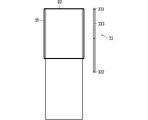
- FIG. 3 is a diagram schematically showing an example of a display image displayed on the display screen 31a of the display 31.
- the display image includes the first window 34 and the second window 35.
- the scroll bar is not attached to the first window 34, and the scroll bar 33 is attached to the second window 35.
- the second window 35 will be mainly focused on.
- the scroll bar 33 includes an element 331 indicating its upper end (corresponding to the first end), an element 332 indicating its lower end (corresponding to the second end), and a scroll box 333.
- the scroll box 333 can be moved vertically between the upper and lower ends of the scroll bar 33.
- the scroll box 333 may also be referred to as a knob, valve, thumb, crawler or scroll thumb.
- the display 31 displays a part of the display source data D2 on the display screen 31a together with the scroll bar 33.
- the display source data D2 and the position of the scroll box 333 on the scroll bar 33 will be described.
- 4 to 6 are diagrams schematically showing an example of the relationship between the position of the scroll box 333 and the position of the image area (here, the second window 35) displayed on the display 31 of the display source data D2. Is.
- the scroll box 333 is located at the upper end position of the scroll bar 33. At this time, the uppermost area of the display source data D2 is displayed in the second window 35.
- the scroll box 333 is located at an intermediate position between the upper end and the lower end of the scroll bar 33. Therefore, at this time, the intermediate region of the display source data D2 is displayed in the second window 35.
- the scroll box 333 is located at the lower end position of the scroll bar 33. Therefore, at this time, the lowermost region of the display source data D2 is displayed in the second window 35.
- the position of the scroll box 333 in the scroll bar 33 indicates the image area displayed in the second window 35 of the display source data D2.
- the state of the scroll bar 33 may include the position and size of the scroll box 333 in the scroll bar 33.
- the storage unit 10 is, for example, a non-volatile storage unit, and as a more specific example, it is a hard disk drive (Hard disk drive, that is, HDD), a read-only memory (that is, ROM), a flash memory, and an erase program.
- Hard disk drive that is, HDD
- ROM read-only memory
- flash memory and an erase program.
- Memory storage medium including non-volatile semiconductor memory, magnetic disk, flexible disk, optical disk, compact disk, mini disk, DVD, etc. such as read only memory (EPROM) and electrically manageable program-only memory (EEPROM), Alternatively, it may be any storage medium used in the future.
- the scroll image data includes, for example, the first scroll image data D31 indicating the scroll bar 33 in a state where the scroll box 333 is not located at the lower end of the scroll bar 33, and the scroll box 333 is located at the lower end of the scroll bar 33.
- the second scroll image data D32 indicating the scroll bar 33 of the above is preset. That is, the first scroll image data D31 and the second scroll image data D32 are stored in the storage unit 10 in advance.
- FIG. 7 and 8 are diagrams schematically showing an example of the first scroll image data D31
- FIG. 9 is a diagram schematically showing an example of the second scroll image data D32.
- the first scroll image data D31 and the second scroll image data D32 are, for example, data obtained by cutting out a part of the display image data D1 and correspond to a lower end region of the scroll bar 33 (corresponding to a partial region on the second end side). It is image data which shows. Both the first scroll image data D31 and the second scroll image data D32 include a part above the element 332 and the element 332.
- the first scroll image data D31 in FIG. 7 does not include the scroll box 333.
- the second scroll image data D32 in FIG. 9 includes a scroll box 333 located at the lower end of the scroll bar 33.
- the specifying unit 2 specifies the state of the scroll bar 33 in the display image data D1 acquired by the image acquisition unit 1 based on the scroll image data stored in the storage unit 10 and the display image data D1. Specifically, the specific unit 2 acquires the first scroll image data D31 and the second scroll image data D32 from the storage unit 10. Then, the specific unit 2 determines whether or not the first scroll image data D31 or the second scroll image data D32 can be detected from the display image data D1.
- the specific unit 2 performs template matching between the display image data D1 and the first scroll image data D31.
- template matching may be performed for each of the first scroll image data D31.
- the display image data D1 contains a first image similar to or matching each first scroll image data D31
- the first image is detected by the template matching.
- the scroll box 333 is located above the lower end position.
- the specific unit 2 also performs template matching between the display image data D1 and the second scroll image data D32.
- the display image data D1 contains a second image similar to or matching the second scroll image data D32
- the second image is detected by the template matching.
- the scroll box 333 is located at the lower end position.
- the image position acquisition unit 3 outputs the position information of the scroll box 333 of the scroll bar 33 to the processing control unit 5. For example, when a first image similar to or matching the first scroll image data D31 is detected by the specific unit 2, the image position acquisition unit 3 tells the processing control unit 5 that the scroll box 333 is at a position other than the lower end position. Notice. Further, when the specific unit 2 detects a second image similar to or matching the second scroll image data D32, the image position acquisition unit 3 notifies the processing control unit 5 that the scroll box 333 is at the lower end position. Further, when neither the first image nor the second image is detected from the display image data D1, the image position acquisition unit 3 may notify the processing control unit 5 to that effect.
- the operation processing unit 4 performs processing related to the operation of the scroll bar 33.
- the operation processing unit 4 operates the scroll bar 33 to scroll the display source data D2 to be displayed on the display 31.
- the operation processing unit 4 instructs the computer main body 32 to operate the scroll bar 33.
- the operation processing unit 4 lowers the scroll box 333 so as to display the image area one page or less below the currently displayed image area of the display source data D2.
- the computer main body 32 is instructed to move to.
- the operation of moving the image area downward by one page is also called a page down operation.
- the operation processing unit 4 may further perform processing related to the screen capture operation.
- the operation processing unit 4 may instruct the computer main body 32 to perform a screen capture operation.
- the computer main body 32 stores the copy data of the display image data D1 displayed on the display 31 in, for example, a non-temporary non-volatile storage unit.
- the processing control unit 5 comprehensively processes the entire screen capture device 20. For example, the processing control unit 5 outputs various instructions to the image acquisition unit 1, the specific unit 2, the image position acquisition unit 3, and the operation processing unit 4, and the image acquisition unit 1, the specific unit 2, and the image position acquisition unit 4. Various information is received from 3 and the operation processing unit 4.
- FIG. 10 is a flowchart showing an example of the operation of the screen capture device 20.
- the processing control unit 5 determines whether or not the screen capture instruction from the automatic test device 40 has been received. When the instruction is not received, the processing control unit 5 executes step S1 again.
- step S2 the processing control unit 5 causes the image acquisition unit 1 to acquire the display image data D1.
- the image acquisition unit 1 acquires the display image data D1 from the computer main body 32.
- the processing control unit 5 causes the operation processing unit 4 to instruct the computer main body 32 to perform the screen capture operation.
- the computer main body 32 stores the copy data of the display image data D1 in the non-temporary non-volatile storage unit as evidence.
- the image acquisition unit 1 may store the display image data D1 in the storage unit.
- the currently displayed display image data D1 is stored in the storage unit as evidence.
- step S3 the processing control unit 5 causes the specific unit 2 to determine whether or not a first image similar to or matching the first scroll image data D31 is detected from the display image data D1. Specifically, the specific unit 2 performs template matching between the display image data D1 acquired by the image acquisition unit 1 and the first scroll image data D31 stored in the storage unit 10. When a plurality of types of first scroll image data D31 are stored in the storage unit 10, the specific unit 2 performs template matching for each of the first scroll image data D31.
- step S3 the processing control unit 5 causes the operation processing unit 4 to operate the scroll bar 33, and displays the undisplayed image area of the display source data D2 with the display 31. It is displayed in the second window 35 of.
- the operation processing unit 4 moves the scroll box 333 to the lower end side on one page or less, and displays an undisplayed image area on the second window 35 of the display 31.
- the operation processing unit 4 instructs the computer main body 32 to perform a page-down operation.
- the computer main body 32 performs a page down operation based on the instruction.
- the image area of the display source data D2 that is one page lower than the image area displayed in the second window 35 is displayed in the second window 35.
- the page-down operation can be realized, for example, by clicking a part of the area between the scroll box 333 and the element 332 in the scroll bar 33 (see, for example, the position P1 in FIG. 7).
- the click position P1 is, for example, a position above the element 332 in the first scroll image data D31 (first image).
- the image position acquisition unit 3 may specify the click position P1 based on the position of the first image detected by the identification unit 2 (see FIGS. 7 and 8), and the operation processing unit 4 may acquire the image position.
- the position P1 specified by the unit 3 may be specified, and the click may be instructed to the computer main body 32.
- the computer main body 32 performs a page down operation by executing a click on the position P1 in response to the instruction.
- step S2 the processing control unit 5 executes step S2 again. That is, the undisplayed image area of the display source data D2 is displayed in the second window 35 by the scroll operation in step S4. Therefore, in order to acquire the displayed contents, the image acquisition unit 1 is displayed in step S2. Acquires the display image data D1 displayed on the display screen 31a.
- the display image data D1 displayed in step S2 is stored in the non-volatile storage unit as evidence by the computer main body 32 or the image acquisition unit 1.
- the set of steps S4 and S2 is repeatedly executed as long as the first image is detected from the display image data D1 in step S3. That is, when the first image is detected, the display source data D2 includes an undisplayed image area. Therefore, the operation processing unit 4 performs a scroll operation to display the undisplayed image area on the display 31. It is displayed on the display screen 31a (step S4). Then, the display image data D1 including the image area displayed on the display screen 31a is acquired and stored (step S2). As a result, the image area of the display source data D2 that has not been acquired yet can be sequentially acquired as the display image data D1 and stored in the storage unit.
- the processing control unit 5 determines in step S5 whether or not the second image is detected from the display image data D1. Let the specific part 2 do it. Specifically, the specific unit 2 performs template matching between the display image data D1 acquired by the image acquisition unit 1 and the second scroll image data D32 stored in the storage unit 10.
- the scroll box 333 When the second image is detected from the display image data D1, the scroll box 333 is located at the lower end position, so the process ends. That is, when the scroll box 333 is located at the lower end position, the image area of the data D2 is sequentially displayed on the display screen 31a by the previous scroll operation (step S4), and the display image data D1 is acquired for each scroll operation. It is stored in the non-volatile storage unit. As a result, the entire image area of the display source data D2 is divided into a plurality of display image data D1 and acquired. In other words, the processing is terminated because sufficient evidence has been obtained.
- the processing control unit 5 determines that an abnormality has occurred in step S6 and performs error processing. That is, when neither the first image nor the second image can be detected from the display image data D1, the processing control unit 5 determines that an abnormality has occurred. As error processing, the processing control unit 5 may display, for example, on the display 31 that the state of the scroll bar 33 could not be specified.
- the state of the scroll bar 33 is specified based on the display image data D1 and the preset scroll image data, and the scroll operation and the scroll operation are performed based on the state of the scroll bar 33. Capture the display screen. According to such a process, it is not necessary to acquire the size information of the display source data D2. In other words, the necessity of the scroll operation can be determined by a method different from the method of acquiring the size information of the display source data D2, and by extension, the entire image area of the display source data D2 is displayed as a plurality of display images. It can be acquired by dividing it into data D1. Therefore, the screen capture device 20 does not need to perform processing corresponding to the data format of the data D2, and the introduction of the screen capture device 20 becomes easy.
- each image area of the display source data D2 can be captured in order from the upper side.
- each image area can be acquired as display image data D1 in order from the upper side.
- the display source data D2 includes an unacquired image area.
- the screen capture device 20 performs template matching between the first scroll image data D31 indicating the lower end region of the scroll bar 33 not including the scroll box 333 and the display image data D1. According to this, the screen capture device 20 can easily identify the state in which the scroll box 333 is not located at the lower end position. In other words, the screen capture device 20 can easily identify that the image area that has not yet been acquired as evidence is not included in the display source data D2 and the scroll operation is necessary.
- the screen capture device 20 performs template matching between the second scroll image data D32 indicating the scroll bar 33 in a state where the scroll box 333 is located at the lower end position and the display image data D1. According to this, the screen capture device 20 can easily identify the state in which all of each image area of the display source data D2 is acquired as evidence.
- the processing control unit 5 when the processing control unit 5 cannot detect both the first image and the second image from the display image data D1 by template matching, it is determined that an abnormality has occurred. Therefore, the processing control unit 5 can perform error processing at an appropriate timing. As error processing, the processing control unit 5 displays, for example, that an abnormality has occurred on the display 31.
- the scroll bar 33 is a vertical scroll bar, it may be a horizontal scroll bar.
- 11 and 12 are diagrams schematically showing an example of the hardware configuration of the screen capture device 20 exemplified in FIG. 1.
- the hardware configurations exemplified in FIGS. 11 and 12 may not match the numbers of the configurations exemplified in FIG. 1, but the configuration exemplified in FIG. 1 is a conceptual unit. It is due to the fact that it is shown.
- FIG. 11 a process for performing an operation as a hardware configuration for realizing an image acquisition unit 1, a specific unit 2, an image position acquisition unit 3, an operation processing unit 4, and a processing control unit 5 in FIG.
- the circuit 21A and the storage device 22 are shown.
- the storage device 22 is, for example, a hard disk drive (Hard disk drive, that is, HDD), a random access memory (random access memory, that is, RAM), a read-only memory (read only memory, that is, ROM), a flash memory, and an erase program.
- Hard disk drive that is, HDD
- random access memory random access memory
- read-only memory read only memory
- flash memory and an erase program.
- Memory storage including volatile or non-volatile semiconductor memory, magnetic disk, flexible disk, optical disk, compact disk, mini disk or DVD such as read only memory (EPROM) and electrically rememberable program-only memory (EEPROM). It may be a medium) or any storage medium that will be used in the future.
- the processing circuit 21A may execute a program stored in a storage device 22, an external CD-ROM, an external DVD-ROM, an external flash memory, or the like. That is, for example, it may be a central processing unit (CPU), a microprocessor, a microcomputer, or a digital signal processor (DSP).
- CPU central processing unit
- DSP digital signal processor
- the image acquisition unit 1 and the specific unit 2 are realized by software, firmware, or a combination of software and firmware in which a program stored in the storage device 22 is executed by the processing circuit 21A. ..
- the functions of the image acquisition unit 1, the specific unit 2, the image position acquisition unit 3, the operation processing unit 4, and the processing control unit 5 may be realized, for example, by linking a plurality of processing circuits. ..
- the software and firmware may be described as a program and stored in the storage device 22.
- the processing circuit 21A realizes the above function by reading and executing the program stored in the storage device 22. That is, the storage device 22 may store a program in which the above functions are eventually realized by being executed by the processing circuit 21A.
- the processing circuit 21B may be dedicated hardware. That is, the processing circuit 21B is, for example, a single circuit, a composite circuit, a programmed processor, a parallel programmed processor, an integrated circuit (application specific integrated circuit, that is, an ASIC), a field-programmable gate array (FPGA). Alternatively, the circuit may be a combination of these.
- the image acquisition unit 1, the specific unit 2, the image position acquisition unit 3, the operation processing unit 4, and the processing control unit 5 are realized by operating the processing circuit 21B.
- the functions of the image acquisition unit 1, the specific unit 2, the image position acquisition unit 3, the operation processing unit 4, and the processing control unit 5 may be realized by separate circuits or may be realized by a single circuit. good.
- the functions of the image acquisition unit 1, the specific unit 2, the image position acquisition unit 3, the operation processing unit 4, and the processing control unit 5 are for executing a program partially stored in the storage device 22. It may be realized in the processing circuit 21B, which is a part of the dedicated hardware.
- the functions of the computer main body 32 and the functions of the automatic test device 40 may be realized by the processing circuit 21A and the storage device 22 or may be realized by the processing circuit 21B, similarly to the screen capture device 20.
- each component in the embodiments described above is a conceptual unit, and within the scope of the art disclosed herein, one component comprises a plurality of structures. It is assumed that one component corresponds to a part of a structure, and further, a case where a plurality of components are provided in one structure is included.
- each component in the above-described embodiment shall include a structure having another structure or shape as long as it exhibits the same function.
- each component described in the above-described embodiment is assumed to be software or firmware and corresponding hardware, and in both concepts, each component is a "part". Alternatively, it is referred to as a "processing circuit” or the like.
- the technique disclosed in the present specification may be provided in a case where each component is distributed and provided in a plurality of devices, that is, a mode such as a system may be used.
Landscapes
- Engineering & Computer Science (AREA)
- General Engineering & Computer Science (AREA)
- Theoretical Computer Science (AREA)
- Human Computer Interaction (AREA)
- Physics & Mathematics (AREA)
- General Physics & Mathematics (AREA)
- User Interface Of Digital Computer (AREA)
Priority Applications (2)
| Application Number | Priority Date | Filing Date | Title |
|---|---|---|---|
| JP2022563271A JP7520143B2 (ja) | 2020-11-17 | 2020-11-17 | 画面キャプチャ装置および画面キャプチャ方法 |
| PCT/JP2020/042789 WO2022107203A1 (ja) | 2020-11-17 | 2020-11-17 | 画面キャプチャ装置および画面キャプチャ方法 |
Applications Claiming Priority (1)
| Application Number | Priority Date | Filing Date | Title |
|---|---|---|---|
| PCT/JP2020/042789 WO2022107203A1 (ja) | 2020-11-17 | 2020-11-17 | 画面キャプチャ装置および画面キャプチャ方法 |
Publications (1)
| Publication Number | Publication Date |
|---|---|
| WO2022107203A1 true WO2022107203A1 (ja) | 2022-05-27 |
Family
ID=81708475
Family Applications (1)
| Application Number | Title | Priority Date | Filing Date |
|---|---|---|---|
| PCT/JP2020/042789 Ceased WO2022107203A1 (ja) | 2020-11-17 | 2020-11-17 | 画面キャプチャ装置および画面キャプチャ方法 |
Country Status (2)
| Country | Link |
|---|---|
| JP (1) | JP7520143B2 (https=) |
| WO (1) | WO2022107203A1 (https=) |
Cited By (1)
| Publication number | Priority date | Publication date | Assignee | Title |
|---|---|---|---|---|
| WO2025159269A1 (ko) * | 2024-01-26 | 2025-07-31 | 주식회사 지엠디소프트 | 안드로이드 기반의 휴대용 단말기에서 실행되는 대화창을 자동 스크롤하여 캡처하는 방법 및 장치 |
Citations (6)
| Publication number | Priority date | Publication date | Assignee | Title |
|---|---|---|---|---|
| JP2005266954A (ja) * | 2004-03-16 | 2005-09-29 | Hitachi Software Eng Co Ltd | 操作情報記録・再生装置 |
| JP2011076152A (ja) * | 2009-09-29 | 2011-04-14 | Hitachi Solutions Ltd | キャプチャシステム |
| US20120221946A1 (en) * | 2011-01-28 | 2012-08-30 | International Business Machines Corporation | Screen Capture |
| JP2014038451A (ja) * | 2012-08-15 | 2014-02-27 | Nomura Research Institute Ltd | 試験装置およびコンピュータプログラム |
| JP2015049520A (ja) * | 2013-08-29 | 2015-03-16 | 富士通株式会社 | シナリオ生成プログラム、シナリオ実行プログラム、シナリオ生成方法、シナリオ実行方法、シナリオ生成装置、及びシナリオ実行装置 |
| JP2017215783A (ja) * | 2016-05-31 | 2017-12-07 | 住友セメントシステム開発株式会社 | テスト装置およびプログラム |
-
2020
- 2020-11-17 JP JP2022563271A patent/JP7520143B2/ja active Active
- 2020-11-17 WO PCT/JP2020/042789 patent/WO2022107203A1/ja not_active Ceased
Patent Citations (6)
| Publication number | Priority date | Publication date | Assignee | Title |
|---|---|---|---|---|
| JP2005266954A (ja) * | 2004-03-16 | 2005-09-29 | Hitachi Software Eng Co Ltd | 操作情報記録・再生装置 |
| JP2011076152A (ja) * | 2009-09-29 | 2011-04-14 | Hitachi Solutions Ltd | キャプチャシステム |
| US20120221946A1 (en) * | 2011-01-28 | 2012-08-30 | International Business Machines Corporation | Screen Capture |
| JP2014038451A (ja) * | 2012-08-15 | 2014-02-27 | Nomura Research Institute Ltd | 試験装置およびコンピュータプログラム |
| JP2015049520A (ja) * | 2013-08-29 | 2015-03-16 | 富士通株式会社 | シナリオ生成プログラム、シナリオ実行プログラム、シナリオ生成方法、シナリオ実行方法、シナリオ生成装置、及びシナリオ実行装置 |
| JP2017215783A (ja) * | 2016-05-31 | 2017-12-07 | 住友セメントシステム開発株式会社 | テスト装置およびプログラム |
Cited By (1)
| Publication number | Priority date | Publication date | Assignee | Title |
|---|---|---|---|---|
| WO2025159269A1 (ko) * | 2024-01-26 | 2025-07-31 | 주식회사 지엠디소프트 | 안드로이드 기반의 휴대용 단말기에서 실행되는 대화창을 자동 스크롤하여 캡처하는 방법 및 장치 |
Also Published As
| Publication number | Publication date |
|---|---|
| JP7520143B2 (ja) | 2024-07-22 |
| JPWO2022107203A1 (https=) | 2022-05-27 |
Similar Documents
| Publication | Publication Date | Title |
|---|---|---|
| CN114530191A (zh) | 自动化测试的方法、计算机装置以及用户接口 | |
| US8947464B2 (en) | Display control apparatus, display control method, and non-transitory computer readable storage medium | |
| CN111052018A (zh) | 伺服电动机调整装置以及伺服电动机调整方法 | |
| JP5253035B2 (ja) | 画像処理装置、画像処理方法、およびプログラム | |
| US10684772B2 (en) | Document viewing apparatus and program | |
| JP4086050B2 (ja) | 情報管理プログラムおよび情報管理装置 | |
| US20220281115A1 (en) | Screen image transition information generation device, screen image transition information generation method, screen image transition information generation program, and screen image transition information generation system | |
| CN102801884A (zh) | 图像处理装置和图像处理方法 | |
| WO2022107203A1 (ja) | 画面キャプチャ装置および画面キャプチャ方法 | |
| JPWO2015063847A1 (ja) | プログラマブル表示器、プログラム | |
| JP2009109880A (ja) | 表示制御装置、表示制御方法、およびプログラム | |
| US20240185628A1 (en) | Client terminal, control method for client terminal, and storage medium | |
| US9304684B2 (en) | Method and apparatus for selecting media files | |
| US20230130917A1 (en) | Image processing apparatus and image processing method | |
| JP2018124758A (ja) | 情報処理装置、情報処理方法、及びプログラム | |
| CN112936220B (zh) | 机器人控制装置 | |
| WO2023068323A1 (ja) | 画像処理装置、画像処理方法及びプログラム | |
| JP2010055641A (ja) | 情報処理装置及びプログラム | |
| JP2019062415A (ja) | 画像処理装置及びプログラム | |
| JP5875340B2 (ja) | 画像検査支援方法及び画像検査支援装置 | |
| JP4888251B2 (ja) | 画像処理装置および画像処理方法 | |
| JP2008257455A (ja) | プログラム、プログラムを記憶した情報記憶媒体、並びに、電子機器 | |
| JP2006350956A (ja) | 情報処理装置及びプログラム | |
| JP6598139B2 (ja) | 表示制御装置、表示制御方法、及びプログラム | |
| JP6099909B2 (ja) | 表示制御装置、その制御方法、およびプログラム、並びに記憶媒体 |
Legal Events
| Date | Code | Title | Description |
|---|---|---|---|
| 121 | Ep: the epo has been informed by wipo that ep was designated in this application |
Ref document number: 20962367 Country of ref document: EP Kind code of ref document: A1 |
|
| ENP | Entry into the national phase |
Ref document number: 2022563271 Country of ref document: JP Kind code of ref document: A |
|
| NENP | Non-entry into the national phase |
Ref country code: DE |
|
| 122 | Ep: pct application non-entry in european phase |
Ref document number: 20962367 Country of ref document: EP Kind code of ref document: A1 |