WO2022102716A1 - 紫外線硬化性樹脂組成物、発光装置及び発光装置の製造方法 - Google Patents
紫外線硬化性樹脂組成物、発光装置及び発光装置の製造方法 Download PDFInfo
- Publication number
- WO2022102716A1 WO2022102716A1 PCT/JP2021/041575 JP2021041575W WO2022102716A1 WO 2022102716 A1 WO2022102716 A1 WO 2022102716A1 JP 2021041575 W JP2021041575 W JP 2021041575W WO 2022102716 A1 WO2022102716 A1 WO 2022102716A1
- Authority
- WO
- WIPO (PCT)
- Prior art keywords
- less
- curable resin
- resin composition
- composition
- ultraviolet curable
- Prior art date
- Legal status (The legal status is an assumption and is not a legal conclusion. Google has not performed a legal analysis and makes no representation as to the accuracy of the status listed.)
- Ceased
Links
Images

Classifications
-
- C—CHEMISTRY; METALLURGY
- C08—ORGANIC MACROMOLECULAR COMPOUNDS; THEIR PREPARATION OR CHEMICAL WORKING-UP; COMPOSITIONS BASED THEREON
- C08F—MACROMOLECULAR COMPOUNDS OBTAINED BY REACTIONS ONLY INVOLVING CARBON-TO-CARBON UNSATURATED BONDS
- C08F222/00—Copolymers of compounds having one or more unsaturated aliphatic radicals, each having only one carbon-to-carbon double bond, and at least one being terminated by a carboxyl radical and containing at least one other carboxyl radical in the molecule; Salts, anhydrides, esters, amides, imides, or nitriles thereof
- C08F222/10—Esters
- C08F222/1006—Esters of polyhydric alcohols or polyhydric phenols
- C08F222/102—Esters of polyhydric alcohols or polyhydric phenols of dialcohols, e.g. ethylene glycol di(meth)acrylate or 1,4-butanediol dimethacrylate
-
- H—ELECTRICITY
- H10—SEMICONDUCTOR DEVICES; ELECTRIC SOLID-STATE DEVICES NOT OTHERWISE PROVIDED FOR
- H10K—ORGANIC ELECTRIC SOLID-STATE DEVICES
- H10K50/00—Organic light-emitting devices
- H10K50/80—Constructional details
- H10K50/84—Passivation; Containers; Encapsulations
- H10K50/844—Encapsulations
-
- C—CHEMISTRY; METALLURGY
- C08—ORGANIC MACROMOLECULAR COMPOUNDS; THEIR PREPARATION OR CHEMICAL WORKING-UP; COMPOSITIONS BASED THEREON
- C08F—MACROMOLECULAR COMPOUNDS OBTAINED BY REACTIONS ONLY INVOLVING CARBON-TO-CARBON UNSATURATED BONDS
- C08F2/00—Processes of polymerisation
- C08F2/46—Polymerisation initiated by wave energy or particle radiation
- C08F2/48—Polymerisation initiated by wave energy or particle radiation by ultraviolet or visible light
- C08F2/50—Polymerisation initiated by wave energy or particle radiation by ultraviolet or visible light with sensitising agents
-
- C—CHEMISTRY; METALLURGY
- C08—ORGANIC MACROMOLECULAR COMPOUNDS; THEIR PREPARATION OR CHEMICAL WORKING-UP; COMPOSITIONS BASED THEREON
- C08F—MACROMOLECULAR COMPOUNDS OBTAINED BY REACTIONS ONLY INVOLVING CARBON-TO-CARBON UNSATURATED BONDS
- C08F220/00—Copolymers of compounds having one or more unsaturated aliphatic radicals, each having only one carbon-to-carbon double bond, and only one being terminated by only one carboxyl radical or a salt, anhydride ester, amide, imide or nitrile thereof
- C08F220/02—Monocarboxylic acids having less than ten carbon atoms; Derivatives thereof
- C08F220/10—Esters
- C08F220/20—Esters of polyhydric alcohols or phenols, e.g. 2-hydroxyethyl (meth)acrylate or glycerol mono-(meth)acrylate
-
- C—CHEMISTRY; METALLURGY
- C08—ORGANIC MACROMOLECULAR COMPOUNDS; THEIR PREPARATION OR CHEMICAL WORKING-UP; COMPOSITIONS BASED THEREON
- C08F—MACROMOLECULAR COMPOUNDS OBTAINED BY REACTIONS ONLY INVOLVING CARBON-TO-CARBON UNSATURATED BONDS
- C08F220/00—Copolymers of compounds having one or more unsaturated aliphatic radicals, each having only one carbon-to-carbon double bond, and only one being terminated by only one carboxyl radical or a salt, anhydride ester, amide, imide or nitrile thereof
- C08F220/02—Monocarboxylic acids having less than ten carbon atoms; Derivatives thereof
- C08F220/52—Amides or imides
- C08F220/54—Amides, e.g. N,N-dimethylacrylamide or N-isopropylacrylamide
-
- C—CHEMISTRY; METALLURGY
- C08—ORGANIC MACROMOLECULAR COMPOUNDS; THEIR PREPARATION OR CHEMICAL WORKING-UP; COMPOSITIONS BASED THEREON
- C08F—MACROMOLECULAR COMPOUNDS OBTAINED BY REACTIONS ONLY INVOLVING CARBON-TO-CARBON UNSATURATED BONDS
- C08F220/00—Copolymers of compounds having one or more unsaturated aliphatic radicals, each having only one carbon-to-carbon double bond, and only one being terminated by only one carboxyl radical or a salt, anhydride ester, amide, imide or nitrile thereof
- C08F220/02—Monocarboxylic acids having less than ten carbon atoms; Derivatives thereof
- C08F220/52—Amides or imides
- C08F220/54—Amides, e.g. N,N-dimethylacrylamide or N-isopropylacrylamide
- C08F220/58—Amides, e.g. N,N-dimethylacrylamide or N-isopropylacrylamide containing oxygen in addition to the carbonamido oxygen, e.g. N-methylolacrylamide, N-(meth)acryloylmorpholine
-
- C—CHEMISTRY; METALLURGY
- C09—DYES; PAINTS; POLISHES; NATURAL RESINS; ADHESIVES; COMPOSITIONS NOT OTHERWISE PROVIDED FOR; APPLICATIONS OF MATERIALS NOT OTHERWISE PROVIDED FOR
- C09K—MATERIALS FOR MISCELLANEOUS APPLICATIONS, NOT PROVIDED FOR ELSEWHERE
- C09K3/00—Materials not provided for elsewhere
- C09K3/10—Materials in mouldable or extrudable form for sealing or packing joints or covers
-
- H—ELECTRICITY
- H05—ELECTRIC TECHNIQUES NOT OTHERWISE PROVIDED FOR
- H05B—ELECTRIC HEATING; ELECTRIC LIGHT SOURCES NOT OTHERWISE PROVIDED FOR; CIRCUIT ARRANGEMENTS FOR ELECTRIC LIGHT SOURCES, IN GENERAL
- H05B33/00—Electroluminescent light sources
- H05B33/02—Details
- H05B33/04—Sealing arrangements, e.g. against humidity
-
- H—ELECTRICITY
- H05—ELECTRIC TECHNIQUES NOT OTHERWISE PROVIDED FOR
- H05B—ELECTRIC HEATING; ELECTRIC LIGHT SOURCES NOT OTHERWISE PROVIDED FOR; CIRCUIT ARRANGEMENTS FOR ELECTRIC LIGHT SOURCES, IN GENERAL
- H05B33/00—Electroluminescent light sources
- H05B33/10—Apparatus or processes specially adapted to the manufacture of electroluminescent light sources
Definitions
- the present disclosure relates to an ultraviolet curable resin composition, a light emitting device, and a method for manufacturing the light emitting device.
- the present invention relates to a light emitting device provided with a stop material and a method for manufacturing a light emitting device using this ultraviolet curable resin composition.
- Organic EL light emitting devices are applied to lighting, displays, etc., and are expected to become widespread in the future.
- an organic EL element is arranged on a support substrate, the organic EL element is covered with an inorganic layer called a passivation layer, and the passivation layer is covered with a sealing material made of an organic resin. There is.
- Patent Document 1 75 to 95 wt. % Polyethylene glycol dimethacrylate monomer and the like, and 4 to 10 wt. % 1-15 wt. With a viscosity in the range of about 14 to about 18 cps at 22 ° C. and a surface tension in the range of about 35 to about 39 dynes / cm at 22 ° C. with pentaerythritol tetraacrylate or the like. It is disclosed that an ink composition containing% of a spread modifier is used to prepare an encapsulant by an inkjet method.
- the encapsulant When the encapsulant is produced by applying the composition by the inkjet method, it is easy to fabricate the encapsulant with high positional accuracy and to reduce the thickness of the encapsulant.
- the encapsulant in order to suppress the invasion of moisture and prevent the deterioration of the organic EL element in the encapsulant, it is required that voids are less likely to occur, and for that purpose, the encapsulant and the underlying inorganic material are in close contact with each other. It is also required to have high properties and to prevent outgas from being generated from the sealing material.
- the subject of the present disclosure is that when the encapsulant for encapsulating the light emitting element is produced by the inkjet method, the surface of the encapsulant is less likely to be uneven, the encapsulant is less likely to generate outgas, and the encapsulant is used.
- Manufacture of an ultraviolet curable resin composition capable of increasing adhesion to an inorganic material, a light emitting device provided with a sealing material made of a cured product of the ultraviolet curable resin composition, and a light emitting device using the ultraviolet curable resin composition. Is to provide a method.
- the ultraviolet curable resin composition is: With compound (A) consisting of at least one selected from the group consisting of N, N-dimethylacrylamide, N, N-diethylacrylamide and N-acryloylmorpholine;
- n is an integer of 1 or more and 3 or less
- R is an alkylene group having 3 or more and 6 or less carbon atoms, but when there are multiple Rs in one molecule
- R is an independently alkylene group having 3 or more and 6 or less carbon atoms
- X is each.
- the light emitting device includes a light emitting element and a sealing material for sealing the light emitting element, and the sealing material includes a cured product of the ultraviolet curable resin composition.
- the method for manufacturing a light emitting device is a method for manufacturing a light emitting device including a light emitting element and a sealing material for sealing the light emitting element, and the ultraviolet curable resin composition is subjected to an inkjet method.
- the present invention comprises applying the above-mentioned UV-curable resin composition by irradiating the ultraviolet-curable resin composition with ultraviolet rays to cure the encapsulant.
- the ultraviolet curable resin composition according to the present embodiment (hereinafter, also referred to as composition (X)) is used for sealing a light emitting element such as an organic EL element.
- the composition (X) contains the compound (A), the compound (B), and the photopolymerization initiator (D), and has a viscosity at 25 ° C. of 1 mPa ⁇ s or more and 40 mPa ⁇ s or less at 40 ° C. At least one of the viscosities of 1 mPa ⁇ s or more and 40 mPa ⁇ s or less is satisfied.
- the composition (X) can be applied by an inkjet method because of the above configuration.
- Compound (A) comprises at least one selected from the group consisting of N, N-dimethylacrylamide, N, N-diethylacrylamide and N-acryloylmorpholine.
- Compound (B) is represented by the following formula.
- n is an integer of 1 or more and 3 or less.
- R is an alkylene group having 3 or more carbon atoms and 6 or less carbon atoms, but when there are a plurality of Rs in one molecule, R is an independently alkylene group having 3 or more carbon atoms and 6 or less carbon atoms.
- Each X is independently a hydrogen atom or a methyl group.
- the photopolymerization initiator (D) contains an acylphosphine oxide compound.
- the base of the inorganic material when the encapsulant is produced on the base of the inorganic material, for example, when the encapsulant is produced on the passivation layer made of an inorganic silicon compound by the inkjet method, the base is uneven. However, unevenness is less likely to be formed on the surface of the encapsulant, and the smoothness of the encapsulant can be improved. Further, the sealing material 5 can have high adhesion to the base of the inorganic material, and can prevent outgas from being generated from the sealing material 5.
- the above effect was realized for the following reasons. Since the above compound (A) can enhance the adhesion between the composition (X) and the inorganic material, the composition (X) tends to wet and spread on the inorganic material, thereby smoothing the sealing material 5. It is presumed that the sex will increase. It is presumed that the compound (B) can enhance the adhesion between the sealing material 5 and the inorganic material. Further, the composition (X) can have good reactivity depending on the combination of the compound (A) and the compound (B) and the acylphosphine oxide compound, whereby the unreacted substance in the encapsulant 5 can be obtained. Is unlikely to remain, and it is presumed that outgas is less likely to occur.
- the combination of the compound (A) and the compound (B) tends to realize the viscosity and surface tension of the composition (X) suitable for the inkjet method. Further, since the compound (A) and the compound (B) are relatively hard to volatilize, the storage stability of the composition (X) is not easily impaired.
- the cured product obtained by irradiating the composition (X) with light and then heating it preferably has a glass transition temperature of 80 ° C. or higher.
- the cured product can have good heat resistance. Therefore, for example, when the cured product is subjected to a treatment accompanied by a temperature rise, the cured product is less likely to deteriorate.
- the glass transition temperature of the cured product is more preferably 90 ° C. or higher, and even more preferably 100 ° C. or higher.
- the viscosity of the composition (X) at 25 ° C. is preferably 1 mPa ⁇ s or more and 40 mPa ⁇ s or less.
- the composition (X) can be applied and molded at room temperature by a casting method, an inkjet method, or the like. If the viscosity is 35 mPa ⁇ s or less, it is more preferable, if it is 30 mPa ⁇ s or less, it is more preferable, if it is 20 mPa ⁇ s or less, it is particularly preferable, and if it is 15 mPa ⁇ s or less, it is most preferable.
- the viscosity is 5 mPa ⁇ s or more, and more preferably 8 mPa ⁇ s or more.
- this viscosity is 8 mPa ⁇ s or more and 35 mPa ⁇ s or less.
- the viscosity of the composition (X) at 40 ° C. is 1 mPa ⁇ s or more and 40 mPa ⁇ s or less.
- the viscosity can be reduced by slightly heating the composition (X). Therefore, if heated, the composition (X) can be easily molded by a method such as a casting method, and the composition (X) can also be molded by an inkjet method. Further, since the composition (X) can be reduced in viscosity without being significantly heated, it is possible to prevent the composition (X) from changing due to volatilization of the components in the composition (X).
- the viscosity is 35 mPa ⁇ s or less, it is more preferable, if it is 30 mPa ⁇ s or less, it is more preferable, if it is 20 mPa ⁇ s or less, it is particularly preferable, and if it is 15 mPa ⁇ s or less, it is most preferable. It is also preferable that the viscosity is 5 mPa ⁇ s or more, and more preferably 8 mPa ⁇ s or more. For example, it is preferable that this viscosity is 8 mPa ⁇ s or more and 35 mPa ⁇ s or less.
- composition (X) at 25 ° C. or 40 ° C. can be achieved by the composition of composition (X) described in detail below.
- the total light transmittance is preferably 90% or more.
- the cured product is applied to an optical component such as a sealing material 5 in the organic EL light emitting device 1, the efficiency of extracting light transmitted through the optical component and emitted to the outside can be particularly improved.
- the light transmittance of such a cured product can also be achieved by the composition of the composition (X) described in detail below.
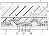
- the surface tension of the composition (X) is 20 mN / cm or more and 40 mN / cm or less.
- the surface tension is 25 mN / cm or more and 40 mN / cm or less, and further preferably 27 mN / cm or more and 38 mN / cm or less.
- the organic EL light emitting device 1 which is an example of the light emitting device will be described.
- EL stands for electroluminescence.
- the organic EL light emitting device 1 includes an organic EL element 4 which is a light emitting element, and a sealing material 5 for covering the organic EL element 4.
- the organic EL element 4 is also called an organic light emitting diode.
- the encapsulant 5 may cover the organic EL element 4 in direct contact with the organic EL element 4, or the organic EL element 4 may have some layer interposed between the encapsulant 5 and the organic EL element 4. May be covered.
- the organic EL light emitting device 1 may be, for example, a lighting device or a display device (display).
- the structure of the organic EL light emitting device 1 will be described.
- the organic EL light emitting device 1 includes an organic EL element 4 (organic light emitting diode), a sealing material 5 for covering the organic EL light emitting element 4, and a passion layer 6.
- the sealing material 5 and the passivation layer 6 overlap each other.
- EL is an abbreviation for electroluminescence.
- the organic EL light emitting device 1 is a top emission type.
- the organic EL light emitting device 1 includes a support substrate 2, a transparent substrate 3 facing the support substrate 2 at a distance, a partition wall 7 (black matrix) on a surface of the support substrate 2 facing the transparent substrate 3, and an organic EL light emitting device.
- the element 4 is provided with a passion layer 6 and a sealing material 5 for covering the organic EL light emitting element 4.
- the support substrate 2 is made of, for example, a resin material, but is not limited thereto.
- the transparent substrate 3 is made of a translucent material.
- the transparent substrate 3 is, for example, a glass substrate or a transparent resin substrate.
- the light emitting element 4 includes, for example, a pair of electrodes 41 and 43 and an organic light emitting layer 42 between the electrodes 41 and 43.
- the organic light emitting layer 42 includes, for example, a hole injection layer 421, a hole transport layer 422, an organic light emitting layer 423, and an electron transport layer 424, and these layers are laminated in the above order.
- the partition wall 7 partitions the surface of the support substrate 2.
- the organic EL element 4 is arranged between two adjacent partition walls 7.
- the partition wall 7 is manufactured, for example, by molding a photosensitive resin material by a photolithography method.
- the partition walls 7 are arranged in a striped pattern, for example, that is, a plurality of partition walls 7 long in one direction are arranged at intervals in a direction orthogonal to the longitudinal direction thereof.
- the arrangement of the partition walls 7 is not limited to the above, and the partition walls 7 may be arranged in a grid pattern, for example.
- the height of the partition wall 7 is, for example, 0.1 ⁇ m or more and 1.5 ⁇ m or less. Further, the distance between the adjacent partition walls 7 is, for example, 30 ⁇ m or more and 150 ⁇ m or less.
- the organic EL element 4 includes, for example, a pair of electrodes 41 and 43 and an organic light emitting layer 42 between the electrodes 41 and 43.
- the organic light emitting layer 42 includes, for example, a hole injection layer 421, a hole transport layer 422, an organic light emitting layer 423, and an electron transport layer 424, and these layers are laminated in the above order.
- the organic EL light emitting device 1 includes a plurality of organic light emitting elements 4, and the plurality of organic EL light emitting elements 4 form an array 9 (hereinafter referred to as an element array 9) on the support substrate 2.
- the element array 9 also includes a connection wiring 8 for electrically connecting the electrodes 43 of the adjacent organic EL light emitting elements 4 and the electron transport layers 424.
- the connection wiring 8 is provided so as to straddle the partition wall 7.
- the partition wall 7 protrudes from the organic EL element 4 on the side opposite to the support substrate 2, and the protrusion dimension of the partition wall 7 from the organic EL element 4 is, for example, 0.1 ⁇ m or more and 1.5 ⁇ m or less.
- the passivation layer 6 is preferably made of silicon nitride or silicon oxide.
- the passivation layer 6 includes a first passivation layer 61 and a second passivation layer 62.
- the first passivation layer 61 covers the organic EL element 4 by covering the element array 9 in a state of being in direct contact with the element array 9.
- the first passivation layer 61 covers the surface of the organic EL element 4 and the top of the partition wall 7 protruding from the organic EL element 4, so that the surface of the first passivation layer 61 is a convex portion according to the arrangement position of the partition wall 7. It has a concavo-convex shape with (see FIG. 2).
- the second passivation layer 62 is arranged at a position opposite to the element array 9 with respect to the first passivation layer 61, and a space is provided between the second passivation layer 62 and the first passivation layer 61. ing.
- the sealing material 5 is filled between the first passivation layer 61 and the second passivation layer 62. That is, the first passivation layer 61 is interposed between the organic EL element 4 and the sealing material 5 that covers the organic EL element 4.
- a second encapsulant 52 is filled between the second passivation layer 62 and the transparent substrate 3.
- the second encapsulant 52 is made of, for example, a transparent resin material.
- the material of the second sealing material 52 is not particularly limited.
- the material of the second encapsulant 52 may be the same as or different from that of the encapsulant 5.
- the passivation layer 6 is preferably made of silicon nitride or silicon oxide, and particularly preferably made of silicon nitride.
- the passivation layer 6 includes a first passivation layer 61 and a second passivation layer 62.
- the first passivation layer 61 covers the light emitting element 4 by covering the element array 9 in a state of being in direct contact with the element array 9.
- the second passivation layer 62 is arranged at a position opposite to the element array 9 with respect to the first passivation layer 61, and a space is provided between the second passivation layer 62 and the first passivation layer 61. ing.
- a sealing material 5 is filled between the first passivation layer 61 and the second passivation layer 62. That is, the first passivation layer 61 is interposed between the light emitting element 4 and the sealing material 5 that covers the light emitting element 4.
- a second encapsulant 52 is filled between the second passivation layer 62 and the transparent substrate 3.
- the second encapsulant 52 is made of, for example, a transparent resin material.
- the material of the second sealing material 52 is not particularly limited.
- the material of the second encapsulant 52 may be the same as or different from that of the encapsulant 5.
- (meth) acrylate means “acrylate or methacrylate”
- (meth) acryloyl group means “acryloyl group or methacryloyl group”.
- di (meth) acrylate means that the two (meth) acrylates may be the same or different.
- composition (X) contains a radically polymerizable compound, and the radically polymerizable compound contains at least the compound (A) and the compound (B).
- compound (A) comprises at least one selected from the group consisting of N, N-dimethylacrylamide, N, N-diethylacrylamide and N-acryloylmorpholine.
- the affinity between the encapsulant 5 and the inorganic material can be enhanced. Therefore, when the composition (X) is applied onto the base of the inorganic material by an inkjet method, the composition (X) tends to get wet and spread on the base, and it is considered that the smoothness of the sealing material 5 is enhanced.
- the compound (A) has a low viscosity and a low volatility. Therefore, the compound (A) can reduce the viscosity of the composition (X) so that it can be applied by an inkjet method, can improve the storage stability of the composition (X), and further remove the outgas from the encapsulant 5. It can be less likely to occur. Further, since the compound (A) has good reactivity, the composition (X) can be efficiently cured to prepare the encapsulant 5.
- the ratio of the compound (A) is preferably 20% by mass or more and 80% by mass or less with respect to the entire composition (X).
- this ratio is 20% by mass or more, the smoothness of the sealing material 5 tends to be particularly enhanced.
- this ratio is 80% by mass or less, the composition (X) and the encapsulant 5 are less likely to absorb moisture excessively, and therefore, the encapsulant 5 is released from the base due to the expansion of the encapsulant 5 due to the moisture. Is unlikely to peel off.
- This ratio is more preferably 25% by mass or more and 70% by mass or less, and further preferably 30% by mass or more and 50% by mass or less.
- a preferred form of compound (A) comprises at least N-acryloylmorpholine.
- the proportion of N-acryloylmorpholine is preferably 5% by mass or more and 60% by mass or less with respect to the entire composition (X).
- this ratio is 5% by mass or more, the photocurability of the encapsulant 5 tends to be particularly enhanced.
- this ratio is 60% by mass or less, it becomes difficult to excessively absorb the moisture of the composition (X) and the encapsulant 5, and therefore, the encapsulant 5 becomes a base due to the expansion of the encapsulant 5 due to the moisture. It is unlikely that it will peel off from the surface.
- This ratio is preferably 20% by mass or more and 55% by mass or less, more preferably 25% by mass or more and 55% by mass or less, and further preferably 30% by mass or more and 50% by mass or less.
- Compound (A) preferably contains N-acryloylmorpholine and preferably contains at least one of N, N-dimethylacrylamide and N, N-diethylacrylamide.
- the ratio of the total amount of N, N-dimethylacrylamide and N, N-diethylacrylamide is preferably 5% by mass or more and 20% by mass or less with respect to the entire composition (X). When this ratio is 5% by mass or more, the smoothness of the sealing material 5 tends to be particularly enhanced.
- this ratio is 20% by mass or less, it becomes difficult to excessively absorb the moisture of the composition (X) and the encapsulant 5, and therefore, the encapsulant 5 is separated from the base by the expansion of the encapsulant 5 due to the moisture. Is unlikely to peel off.
- This ratio is more preferably 5% by mass or more and 18% by mass or less, and further preferably 8% by mass or more and 15% by mass or less.
- the composition (X) may further contain N-substituted (meth) acrylamide (A-3) other than the compound (A).
- N-substituted (meth) acrylamide (A-3) can also enhance the affinity between the composition (X) and the inorganic material.
- N-substituted (meth) acrylamide (A-3) is, for example, N, N-dimethylmethacrylamide, N, N-diethylmethacrylamide, N-methyl (meth) acrylamide, N-ethyl (meth) acrylamide, N-methyl.
- N-ethyl (meth) acrylamide N-normal propyl (meth) acrylamide, N-isopropyl (meth) acrylamide, N-hydroxyethyl (meth) acrylamide and the like.
- the proportion of N-substituted (meth) acrylamide (A-3) in the composition (X) is preferably 10% by mass or less.
- compound (B) is represented by the following general formula (1).
- n is an integer of 1 or more and 3 or less.
- R is an alkylene group having 3 or more carbon atoms and 6 or less carbon atoms, but when there are a plurality of Rs in one molecule, R is an independently alkylene group having 3 or more carbon atoms and 6 or less carbon atoms.
- Each X is an H or a methyl group independently.
- the compound (B) Since the compound (B) has polarity, the affinity between the encapsulant 5 and the inorganic material can be enhanced. Therefore, when the composition (X) is applied onto the base of the inorganic material by an inkjet method, the composition (X) tends to get wet and spread on the base, and it is considered that the smoothness of the sealing material 5 is enhanced. Further, when the carbon number of R is 3 or more, the encapsulant 5 can hardly absorb water excessively, and therefore the expansion of the encapsulant 5 due to the absorption of water can be suppressed. It is considered that this also enhances the smoothness of the sealing material 5.
- compound (B) has a low viscosity and low volatility. Therefore, the compound (B) can reduce the viscosity of the composition (X) so that it can be applied by an inkjet method, can improve the storage stability of the composition (X), and further remove the outgas from the encapsulant 5. It can be less likely to occur. Further, since the compound (B) has good reactivity, the composition (X) can be efficiently cured to prepare the encapsulant 5. In addition, compound (B) can increase the glass transition temperature of the encapsulant 5. Therefore, the heat resistance of the sealing material 5 can be improved.
- Compound (B) may contain at least one selected from the group consisting of dipropylene glycol diacrylate, tripropylene glycol diacrylate, neopentyl glycol diacrylate and 3-methyl-1,5-pentanediol diacrylate. preferable. In this case, the above-mentioned action of the compound (B) is particularly easy to obtain.
- the ratio of the compound (B) is preferably 5% by mass or more and 75% by mass or less with respect to the entire composition (X).
- this ratio is 5% by mass or more, the outgas from the sealing material 5 can be reduced. Further, when this ratio is 75% by mass or less, there is an advantage that the smoothness of the sealing material 5 is particularly likely to be improved.
- This ratio is more preferably 15% by mass or more and 65% by mass or less, and further preferably 25% by mass or more and 60% by mass or less.
- composition (X) is a monofunctional (meth) acrylic compound (B2) and a bifunctional (meth) compound other than the above compound (A), N-substituted (meth) acrylamide (A-3) and compound (B). ) At least one of the acrylic compound (B3) may be further contained.
- the monofunctional (meth) acrylate (B2) is, for example, an esterified product of an alcohol having 2 to 30 carbon atoms and (meth) acrylic acid, a benzyl (meth) acrylate, a phenoxyethyl (meth) acrylate, a tetrahydrofurfuryl acrylate, o-,.
- the bifunctional (meth) acrylic compound (B3) is, for example, an esterified product of a polyhydric (preferably 2 to 8-valent) alcohol having 2 to 30 carbon atoms and a (meth) acrylic acid, and a polyvalent (preferably) polyhydric compound having 2 to 30 carbon atoms.
- composition (X) preferably further contains a compound (C) having three or more (meth) acryloyl groups in one molecule.
- the compound (C) can increase the reactivity of the composition (X) and can increase the glass transition temperature of the encapsulant 5 to increase the heat resistance.
- Compound (C) has, for example, a trifunctional (meth) acryloyl compound having three (meth) acryloyl groups, a tetrafunctional (meth) acryloyl compound having four (meth) acryloyl groups, and five (meth) acryloyl groups. It contains at least one selected from the group consisting of a pentafunctional (meth) acryloyl compound and a hexafunctional (meth) acryloyl compound having 6 (meth) acryloyl groups.
- the trifunctional (meth) acryloyl compound is, for example, an esterified product of a trihydric or higher (preferably 3 to 8 valent) alcohol having 3 to 30 carbon atoms and (meth) acrylic acid [for example, tri (meth) acrylate of glycerin, trimethylolpropane. Tri (meth) acrylate, tri (meth) acrylate of pentaerythritol], and alkylene oxides of trivalent or higher (preferably 3 to 8 valent) alcohols having 3 to 30 carbon atoms (2 to 4 carbon atoms in the alkylene group).
- It contains at least one selected from the group consisting of 1 to 30 molar adducts and esterifieds of (meth) acrylic acid [eg, tri (meth) acrylates of the ethylene oxide adduct of trimethylolpropane].
- the tetrafunctional (meth) acryloyl compound is, for example, an esterified product of a tetravalent or higher (preferably 4 to 8 valent) alcohol having 5 to 30 carbon atoms and (meth) acrylic acid [for example, tetra (meth) acrylate and dipenta of pentaerythritol. Tetra (meth) acrylate of erythritol]; and an alkylene oxide (2 to 4 carbon atoms of the alkylene group) 1 to 30 mol adduct of a tetravalent or higher (preferably 4 to 8 valent) alcohol having 5 to 30 carbon atoms.
- the pentafunctional (meth) acryloyl compound and the hexafunctional (meth) acryloyl compound are, for example, an esterified product of a tetravalent or higher (preferably 4 to 8 valent) alcohol having 5 to 30 carbon atoms and (meth) acrylic acid [for example, dipentaerythritol].
- the compound (C) preferably contains at least one of a trifunctional (meth) acryloyl compound and a tetrafunctional (meth) acryloyl compound, and is preferably a tri (meth) acrylate of trimethylolpropane and a tri (meth) of pentaerythritol. It is more preferred to contain at least one selected from the group consisting of acrylates and tetra (meth) acrylates of pentaerythritol.
- the ratio of the compound (C) is preferably more than 0% by mass and 10% by mass or less with respect to the entire composition (X). When this ratio is 10% by mass or less, the increase in viscosity of the composition (X) is suppressed. This ratio is more preferably 8% by mass or less, still more preferably 5% by mass or less.
- the composition (X) contains a photopolymerization initiator (D), and the photopolymerization initiator (D) contains an acylphosphine oxide compound. Therefore, as described above, outgas can be less likely to be generated from the sealing material 5.
- Acylphosphine oxide compounds include, for example, 2,4,6-trimethylbenzoyldiphenylphosphine oxide, bis- (2,6-dimethoxybenzoyl) -2,4,4-trimethylpentylphosphine oxide, diphenyl (2,4,6). -Contains at least one selected from the group consisting of (trimethylbenzoyl) phosphine oxide and bis (2,4,6-trimethylbenzoyl) -phenylphosphin oxide and the like.
- the photopolymerization initiator (D) may further contain a compound other than the acylphosphine oxide compound, for example, a benzoin compound, an acetophenone compound, an anthraquinone compound, a thioxanthone compound, a ketal compound, a benzophenone compound, or an ⁇ -aminoalkylphenone compound. And at least one selected from the group consisting of oxime ester compounds and the like may be further contained.
- a compound other than the acylphosphine oxide compound for example, a benzoin compound, an acetophenone compound, an anthraquinone compound, a thioxanthone compound, a ketal compound, a benzophenone compound, or an ⁇ -aminoalkylphenone compound.
- a compound other than the acylphosphine oxide compound for example, a benzoin compound, an acetophenone compound, an anthraquinone compound
- the benzoin compound is a group consisting of, for example, benzoin, benzoin methyl ether, benzoin ethyl ether, benzoin propyl ether, benzoin isobutyl ether, 2-hydroxy-2-methyl-1-phenylpropan-1-one, 1-hydroxycyclohexylphenylketone and the like. Contains at least one selected from.
- the acetophenone compound is, for example, acetophenone, 2,2-diethoxy-2-phenylacetophenone, 2,2-diethoxy-2-phenylacetophenone, 1,1-dichloroacetophenone, 2-hydroxy-2-methyl-phenylpropane-1-one.
- the anthraquinone compound contains at least one selected from the group consisting of, for example, 2-ethylanthraquinone, 2-t-butyl anthraquinone, 2-chloroanthraquinone, 2-amyl anthraquinone and the like.
- the thioxanthone compound contains at least one selected from the group consisting of, for example, 2,4-diethylthioxanthone, 2-isopropylthioxanthone, 2-chlorothioxanthone and the like.
- the ketal compound contains at least one selected from the group consisting of, for example, acetophenone dimethyl ketal, benzyl dimethyl ketal and the like.
- the benzophenone compound contains at least one selected from the group consisting of, for example, benzophenone, 4-benzoyl-4'-methyldiphenylsulfide and 4,4'-bismethylaminobenzophenone.
- the ⁇ -aminoalkylphenone compound is, for example, 2-methyl-1- (4-methylthiophenyl) -2-morpholinopro-butanone-1 and 2- (dimethylamino) -2-[(4-methylphenyl) methyl]-. It contains at least one selected from the group consisting of 1- [4- (4-morpholinyl) phenyl] -1-butanone] and the like.
- Oxime ester compounds include 1,2-octanedione, 1- [4- (phenylthio)-, 2- (O-benzoyloxime)] and etanone-1- [9-ethyl-6- (2-methylbenzoyl)-. It contains at least one selected from the group consisting of 9H-carbazole-3-yl] -1- (O-acetyloxime) and the like.
- the proportion of the acylphosphine oxide compound is preferably 5% by mass or more and 20% by mass or less with respect to the entire composition (X).
- this ratio is 5% by mass or more, the reactivity of the composition (X) can be particularly enhanced and the generation of outgas from the encapsulant 5 can be particularly suppressed.
- this ratio is 20% by mass or less, the viscosity of the composition (X) can be easily kept low.
- This ratio is more preferably 6% by mass or more and 19% by mass or less, and further preferably 7% by mass or more and 18% by mass or less.
- composition (X) preferably contains a surfactant (E).
- E a surfactant
- the surfactant (E) preferably contains at least one of a silicone-based surfactant and a fluorine-based surfactant.
- the composition (X) is more likely to get wet and spread on the inorganic material, and therefore the smoothness of the sealing material 5 is more likely to be improved.
- the surfactant (E) contains a silicone-based surfactant
- the composition (X) tends to wet and spread beyond the base and the convex portion. That is, for example, when the base of the inorganic material has a striped convex portion as shown in FIG. 2, when the composition (X) is applied on the base, the composition (X) has a length of the convex portion on the base. It becomes easy to get wet and spread in the direction orthogonal to the direction. Therefore, the smoothness of the sealing material 5 tends to be particularly improved.
- the surfactant (E) may contain components other than the silicone-based surfactant and the fluorine-based surfactant.
- the ratio of the surfactant (E) is preferably 0.02% by mass or more and 1.0% by mass or less with respect to the entire composition (X).
- this ratio is 0.02% by mass or more, the wettability of the composition (X) to the inorganic material becomes particularly high, so that the smoothness of the sealing material 5 tends to be particularly high.
- this ratio is 1% by mass or less, the coating film produced by applying the composition (X) on the substrate is less likely to foam, so that the smoothness of the sealing material 5 tends to be improved.
- the composition (X) may contain various additives in order to exhibit various functionalities as needed.
- the additives are light stabilizers, surface treatment agents, antioxidants, anti-aging agents, cross-linking accelerators, polymerization inhibitors, plasticizers, preservatives, pH regulators, defoamers, and moisturizers. It can contain at least one selected from the group consisting of agents and the like.
- the ratio of the total amount of the additive is, for example, 1.0% by mass or less, 0.5% by mass or less, or 0.4% by mass or less with respect to the total amount of the composition (X). Further, this ratio is, for example, 0.05% by mass or more.
- the composition (X) may further contain a hygroscopic agent (F).
- a hygroscopic agent (F) When the composition (X) contains the hygroscopic agent (F), the cured product can have excellent hygroscopicity.
- the average particle size of the hygroscopic agent (F) is preferably 200 nm or less. In this case, the cured product can have high transparency even though it contains the hygroscopic agent (F). Further, when the composition (X) is applied by an inkjet method, if the average particle size of the hygroscopic agent (F) is 200 nm or less, the composition (X) is less likely to be clogged in the nozzle.
- the surface of the sealing material 5 can have good smoothness.
- the hygroscopic agent (F) is preferably an inorganic particle having hygroscopicity, and contains at least one component selected from the group consisting of, for example, zeolite particles, silica gel particles, calcium chloride particles, and titanium oxide nanotube particles. Is preferable. It is particularly preferable that the hygroscopic agent (F) contains zeolite particles.
- the average particle size of the hygroscopic agent (F) is preferably 10 nm or more and 200 nm or less. When the average particle size is 200 nm or less, the sealing material 5 can have particularly high transparency. Further, when the average particle size is 10 nm or more, good hygroscopicity of the hygroscopic agent (F) can be maintained.
- the average particle size is the median diameter calculated from the measurement result by the dynamic light scattering method, that is, the cumulative 50% diameter (D50). As the measuring device, the Nanotrac Wave series manufactured by Microtrac Bell Co., Ltd. can be used.
- the average particle size of the hygroscopic agent (F) is more preferably 150 nm or less, further preferably 100 nm or less, and particularly preferably 70 nm or less. Further, the average particle size of the hygroscopic agent (F) is preferably 20 nm or more, and more preferably 50 nm or more. In this case, the sealing material 5 can have particularly good transparency and hygroscopicity.
- the cumulative 90% diameter (D90) of the hygroscopic agent (F) is 100 nm or less.
- the cured product can have particularly high transparency.
- the ratio of the hygroscopic agent (F) to the total amount of the composition (X) is preferably 1% by mass or more and 20% by mass or less.
- the ratio of the hygroscopic agent (F) is 1% by mass or more, the cured product can have particularly high hygroscopicity.
- the proportion of the hygroscopic agent (F) is 20% by mass or less, the viscosity of the composition (X) can be particularly reduced, and the composition (X) has a sufficiently low viscosity that can be applied by an inkjet method. You can also.
- the proportion of the hygroscopic agent (F) is more preferably 3% by mass or more, and particularly preferably 5% by mass or more.
- the proportion of the hygroscopic agent (F) is more preferably 15% by mass or less, and particularly preferably 13% by mass or less.
- the composition (X) may further contain an inorganic filler other than the hygroscopic agent (F).
- the composition (X) preferably contains nano-sized high-refractive index particles.
- high refractive index particles include zirconia particles.
- the cured product can have a high refractive index while maintaining good transparency of the cured product. Therefore, it is possible to improve the efficiency of taking out the light transmitted to the outside through the sealing material 5 in the organic EL light emitting device 1.
- the average particle size of the high-refractive index particles is preferably in the range of 5 to 30 nm, and more preferably in the range of 10 to 20 nm.
- the proportion of high-refractive index particles in the composition (X) is appropriately designed so that the encapsulant 5 has a desired refractive index.
- the high refractive index particles are preferably contained in the composition (X) so that the refractive index of the cured product is in the range of 1.45 or more and less than 1.55. In this case, the light extraction efficiency of the organic EL light emitting device 1 is particularly improved.
- the composition (X) contains a hygroscopic agent (F)
- the composition (X) further contains a dispersant (G).
- the dispersant (G) can improve the dispersibility of the hygroscopic agent (F) in the composition (X). Therefore, in the composition (X), the increase in viscosity and the decrease in storage stability due to the hygroscopic agent (F) are unlikely to occur.
- the dispersant (G) is a surfactant that can be adsorbed on the particles.
- the dispersant (G) has an adsorbing group (generally also referred to as an anchor) that can be adsorbed on the particles and a molecular skeleton (generally also referred to as a tail) that adheres to the particles when the adsorbing group is adsorbed on the particles.
- the dispersant (G) is, for example, an acrylic dispersant having an acrylic molecular chain at the tail, a urethane dispersant having a urethane molecular chain at the tail, and a polyester-based dispersion having a polyester molecular chain at the tail. It contains at least one ingredient selected from the group if it is an agent.
- the adsorbent group contains, for example, at least one of a basic polar functional group and an acidic polar functional group.
- the basic polar functional group includes, for example, at least one group selected from the group consisting of an amino group, an imino group, an amide group, an imide group, and a nitrogen-containing heterocyclic group.
- the acidic polar functional group includes, for example, at least one group selected from the group consisting of a carboxyl group and a phosphoric acid group.
- the dispersant (G) is at least one compound selected from the group consisting of, for example, Solsperth series manufactured by Nippon Louvre Resol Co., Ltd., DISPERBYK series manufactured by Big Chemie Japan Co., Ltd., and Ajinomoto Fine Techno Co., Ltd. Can be contained.
- the amount of the dispersant (G) with respect to 100 parts by mass of the hygroscopic agent (F) is preferably 5 parts by mass or more and 60 parts by mass or less.
- the amount of the dispersant (G) is 5 parts by mass or more, the function of the dispersant (G) can be effectively exhibited, and when it is 60 parts by mass or less, the dispersant (G) in the encapsulant 5 is used. It is possible to prevent the free molecules of the material from inhibiting the adhesion between the sealing material 5 and the member made of the inorganic material.
- the amount of the dispersant (G) is more preferably 15 parts by mass or more, more preferably 50 parts by mass or less, further preferably 40 parts by mass or less, and particularly preferably 30 parts by mass or less. preferable.
- the composition (X) does not contain a solvent, or the solvent content is preferably 1% by mass or less. In this case, it is not necessary to dry the composition (X) to volatilize the solvent when producing the cured product from the composition (X). In addition, the storage stability of the composition (X) is further enhanced.
- the content of the solvent is more preferably 0.5% by mass or less, further preferably 0.3% by mass or less, and particularly preferably 0.1% by mass or less. It is particularly preferable that the composition (X) does not contain a solvent or contains only a solvent that is inevitably mixed.
- composition (X) can be prepared by mixing the above-mentioned components.
- the composition (X) is preferably liquid at 25 ° C.
- the water content of the composition (X) is preferably 100 ppm or less, more preferably 70 ppm or less, and particularly preferably 50 ppm or less from the viewpoint of reducing outgas.
- the composition (X) is molded by an inkjet method to prepare a coating film, and then the coating film is irradiated with ultraviolet rays to the composition (X) and subsequently heated to form a sealing material 5. It is preferable to prepare.
- the composition (X) can be applied and molded by an inkjet method.
- composition (X) When the composition (X) is applied by an inkjet method, when the composition (X) has a sufficiently low viscosity at room temperature, for example, when the viscosity at 25 ° C. is 30 mPa ⁇ s or less, particularly 15 mPa ⁇ s or less. Can be formed by applying the composition (X) by an inkjet method without heating.
- the composition (X) When the composition (X) has a property of lowering the viscosity by heating, the composition (X) may be heated and then the composition (X) may be applied and molded by an inkjet method.
- the viscosity of the composition (X) at 40 ° C. is 30 mPa ⁇ s or less, particularly 15 mPa ⁇ s or less, the viscosity of the composition (X) can be reduced by slightly heating, and the viscosity is reduced.
- the composition (X) can be ejected by an inkjet method.
- the heating temperature of the composition (X) is, for example, 20 ° C. or higher and 50 ° C. or lower.
- the light irradiated to the coating film is, for example, ultraviolet rays.
- Ultraviolet rays mean light rays having a wavelength in the range of 200 nm or more and 410 nm or less.
- the wavelength of the light irradiating the coating film is preferably in the range of 350 nm or more and 410 nm or less, and more preferably 385 nm or more and 405 nm or less.
- the wavelength of the light irradiating the coating film is not limited to the above description as long as the coating film can be cured.
- the irradiation intensity of the light irradiating the coating film is preferably 20 mW / m 2 or more and 20 W / cm 2 or less.
- the light irradiation intensity is not limited to the above description as long as the coating film can be cured.
- the shape of the portion irradiated with light when the coating film is irradiated with light may be an area type having a certain area or a line type.
- the entire coating film can be irradiated with light by moving the coating film with respect to the light source or moving the light source with respect to the coating film. In this case, it is easy to adjust the time for irradiating the coating film with light, and it is easy to adjust the integrated light amount by adjusting this time.
- the coating film may be cured by irradiating the coating film with light in the atmosphere.
- the reaction of the composition (X) can be allowed to proceed and be cured even in the atmosphere.
- the heating temperature is preferably 90 ° C. or higher. In this case, the curing of the coating film is further promoted, and the coefficient of linear expansion of the sealing material 5 is likely to be lowered.
- the support board 2 is prepared.
- a partition wall 7 black matrix
- a photolithography method using, for example, a photosensitive resin material.
- a plurality of organic EL elements 4 are provided on one surface of the support substrate 2.
- the organic EL element 4 can be manufactured by an appropriate method such as a vapor deposition method or a coating method.
- the element array 9 is manufactured on the support substrate 2.
- the first passivation layer 61 is provided so as to cover the organic EL element 4 and the partition wall 7.
- the first passivation layer 61 can be manufactured by a vapor deposition method such as a plasma CVD method. As shown in FIG. 2, the surface of the first passivation layer 61 has a concavo-convex shape having a convex portion corresponding to the arrangement position of the partition wall 7 (see FIG. 2).
- the composition (X) is applied onto the first passivation layer 61 by an inkjet method to prepare a coating film. If the inkjet method is applied to both the formation of the organic EL element 4 and the coating of the composition (X), the production efficiency of the organic EL light emitting device 1 can be particularly improved. Subsequently, the coating film is cured by irradiating it with ultraviolet rays to produce a sealing material 5. In this embodiment, as described above, the surface of the sealing material 5 can be easily smoothed.
- the thickness of the sealing material 5 is, for example, 2 ⁇ m or more and 50 ⁇ m or less.
- the thickness of the sealing material 5 is preferably 2 ⁇ m or more and 30 ⁇ m or less, and more preferably 2 ⁇ m or more and 15 ⁇ m or less.
- a thin encapsulant 5 having a thickness of 2 ⁇ m or more and 15 ⁇ m or less.
- a second passivation layer 62 is provided on the sealing material 5.
- the second passivation layer 62 can be manufactured by a vapor deposition method such as a plasma CVD method.
- a vapor deposition method such as a plasma CVD method.
- an ultraviolet curable resin material is provided on one surface of the support substrate 2 so as to cover the second passivation layer 62, and then the transparent substrate 3 is superposed on this resin material.
- the transparent substrate 3 is, for example, a glass substrate or a transparent resin substrate.
- ultraviolet rays are irradiated from the outside toward the transparent substrate 3. Ultraviolet rays pass through the transparent substrate 3 and reach the ultraviolet curable resin material. As a result, the ultraviolet curable resin material is cured, and the second encapsulant 52 is produced.
- compositions of Examples and Comparative Examples were prepared by mixing the components shown in the "Composition" column of the table below.
- N-dimethylacrylamide Product: DMAA, manufactured by KJ Chemicals Co., Ltd. -N-Acryloyl morpholine: Trade name ACMO, manufactured by KJ Chemicals Co., Ltd. -N, N-diethylacrylamide: Trade name DEAA, manufactured by KJ Chemicals Co., Ltd. -N-Hydroxyethyl acrylamide: Trade name HEAA, manufactured by KJ Chemicals Co., Ltd. -Dipropylene glycol diacrylate: Trade name NK ester APG-100, manufactured by Shin Nakamura Chemical Industry Co., Ltd.
- -Tripropylene glycol diacrylate Trade name NK ester APG-200, manufactured by Shin Nakamura Chemical Industry Co., Ltd.
- -Neopentyl glycol diacrylate Trade name Light Acrylate NP-A, manufactured by Kyoeisha Chemical Co., Ltd. -3-Methyl-1,5-pentanediol diacrylate: Trade name Light Acrylate MPD-A, manufactured by Kyoeisha Chemical Co., Ltd. -Diethylene glycol diacrylate: Trade name Funkril FA-222A, manufactured by Hitachi Kasei Co., Ltd.
- -Polyethylene glycol diacrylate Trade name NK ester A-400, manufactured by Shin Nakamura Chemical Industry Co., Ltd.
- -Polypropylene glycol diacrylate Trade name NK ester APG-400, manufactured by Shin Nakamura Chemical Industry Co., Ltd.
- -Pentaerythritol triacrylate Trade name Light Acrylate PE-3A, manufactured by Kyoeisha Chemical Co., Ltd. -Dipentaerythritol hexaacrylate, trade name Neomer DA-600, manufactured by Sanyo Chemical Industries, Ltd. -Bis (2,4,6-trimethylbenzoyl) -Phenylphofin oxide, trade name Omnirad819, manufactured by IGM Resin.
- -Diphenyl (2,4,6-trimethylbenzoyl) phosphine oxide trade name Omnirad TPO H, manufactured by IGM Resin.
- -2-Methyl-1- [4- (methylthio) phenyl] -2-morpholinopropane-1-one trade name Omnirad907, manufactured by IGM Resin.
- -Antracure UVS-581 Made by Kawasaki Kasei Kogyo Co., Ltd.
- -Silicone-based surfactant 1 Product name TEGO Twin4000, manufactured by Evonik Industries.
- -Silicone-based surfactant 2 Brand name TEGO Twin4200, manufactured by Evonik Industries.
- -Fluorine-based surfactant Trade name Surflon S-386, manufactured by AGC Seimi Chemical Co., Ltd.
- Viscosity The viscosity of the composition was measured using an E-type viscometer (TVE-35 manufactured by Toki Sangyo Co., Ltd.) under the conditions of a rotation speed of 20 rpm and a temperature of 25 ° C.
- a prebake film was prepared by applying a photosensitive polyimide resin (manufactured by Toray Industries, Inc., product name Photoneece DL-1000) on a glass substrate and then heating at 120 ° C. for 3 minutes using a hot plate. The thickness of the prebake film was measured with a spectrophotometer (U-4100) of Hitachi High Technology and found to be 2 ⁇ m.
- This prebake film was exposed through Photomax, developed by exposing it to a developing solution (2.38% by mass solution of tetramethylammonium hydroxide) for 60 seconds, and further heated at 250 ° C. for 60 minutes in a clean oven.
- partition walls black matrix having a height of 0.5 ⁇ m arranged in a grid pattern were produced on the glass substrate.
- the plan view dimension of the opening surrounded by the partition wall is 70 ⁇ m ⁇ 250 ⁇ m.
- a silicon nitride film having a thickness of 500 nm was formed so as to cover the partition wall on the entire surface of the glass substrate on which the partition wall was formed.
- the composition is placed in a cartridge of an inkjet printer (manufactured by Fujifilm, Material Printer MP2831), and after confirming that the composition in the cartridge can be ejected from the nozzle of the inkjet printer, the droplet of the composition is discharged from the nozzle at 600 dpi.
- a coating film having a maximum thickness of 5 ⁇ m was prepared by discharging under the conditions of.
- the coating film was observed immediately before irradiation with light 5 minutes after the coating film was prepared, and the case where the surface of the coating film was flat was evaluated as "A".
- the concentration of outgas generated from the composition was specified based on the peak area of the obtained gas chromatogram.
- the outgas concentration is the volume fraction of outgas in the gas phase of the vial with respect to the volume of the vial (22 mL).
- the concentration of outgas was specified using toluene as a reference substance. Specifically, by volatilizing toluene in a vial, two reference samples having a toluene concentration of 1000 ppm and 100 ppm were prepared. Each reference sample was introduced into a gas chromatograph and analyzed. From the peak areas of the two chromatograms obtained thereby, the relationship between the peak area and the concentration was defined, and based on this result, the mass ratio of the concentration of outgas was specified and evaluated according to the following criteria. In addition, in order to prevent outgas from being generated, the result is preferably 200 ppm or less, more preferably 100 ppm or less, further preferably 70 ppm or less, and particularly preferably 50 ppm or less. A: 50 ppm or less. B: More than 50ppm and 70ppm or less. C: Over 100 ppm.
- Adhesion The composition is applied to the surface of a silica glass piece (dimensions 50 mm ⁇ 25 mm ⁇ 1 mm) in which a SiN film having a refractive index of 1.83 and a thickness of 0.5 ⁇ m is formed on the surface by a plasma CVD method. A coating film having a thickness of 50 ⁇ m was prepared. On top of this coating film, another piece of quartz glass was layered so that the size of the region where the two came into contact was 12.5 mm ⁇ 25 mm.
- the composition is photocured by irradiating the composition with ultraviolet rays under the conditions of a peak wavelength of 395 nm, an irradiation intensity of 5 W / cm 2 , and an integrated light amount of 3000 mJ / cm 2 using an LED-UV irradiator manufactured by CCS Co., Ltd. in an atmospheric atmosphere. I let you.
- the adhesion strength between the two quartz glass pieces was measured by performing a tensile shear (tensile speed 5 mm / min) test according to JIS K6850. The results were evaluated according to the following criteria. A: 15N / mm 2 or more. B: 5N / mm 2 or more and less than 15N / mm 2 . C: Less than 5N / mm 2 .
- the compositions of Examples 1 to 27 have a low initial viscosity and are excellent in inkjet properties and smoothness. Further, outgas is less likely to be generated from the cured product obtained by curing the compositions of Examples 1 to 27, and the adhesion to the inorganic material is excellent.
- Comparative Example 1 containing no compound (A) has poor wettability with an inorganic material, poor smoothness, and poor adhesion.
- the composition of Comparative Example 2 containing only N-substituted (meth) acrylamide (A-3) other than the compound (A) has poor smoothness and poor adhesion as in Comparative Example 1.
- Comparative Example 2 is not suitable for the inkjet method because it has a high viscosity and poor inkjet properties.
- Comparative Example 3 containing no bifunctional (meth) acrylic compound, outgas is likely to be generated from the encapsulant.
- Comparative Examples 4 to 6 containing the bifunctional (meth) acrylic compound (B3) but not the compound (B) have poor adhesion of the encapsulant.
- Comparative Example 7 containing no acylphosphine oxide-based initiator, outgas is likely to be generated from the encapsulant.
Landscapes
- Chemical & Material Sciences (AREA)
- Organic Chemistry (AREA)
- Health & Medical Sciences (AREA)
- Chemical Kinetics & Catalysis (AREA)
- Medicinal Chemistry (AREA)
- Polymers & Plastics (AREA)
- Engineering & Computer Science (AREA)
- Physics & Mathematics (AREA)
- Optics & Photonics (AREA)
- Manufacturing & Machinery (AREA)
- Materials Engineering (AREA)
- Electroluminescent Light Sources (AREA)
Abstract
有機EL素子の封止材をインクジェット法で作製するにあたり、封止材の表面に凹凸を生じさせにくく、封止材からアウトガスを発生させにくく、かつ封止材と無機質材との密着性を高くできる紫外線硬化性樹脂組成物を提供する。紫外線硬化性樹脂組成物は、N,N-ジメチルアクリルアミド(A-1)等からなる群から選択される少なくとも一種からなる化合物(A)と、CH2CXCO-O-(R-O)n-COCXCH2の式で示される化合物(B)と、アシルフォスフィンオキサイド化合物を含有する光重合開始剤(D)とを含有し、25℃での粘度が1mPa・s以上40mPa・s以下と、40℃における粘度が1mPa・s以上40mPa・s以下とのうち、少なくとも一方を満たす。
Description
本開示は、紫外線硬化性樹脂組成物、発光装置及び発光装置の製造方法に関し、詳しくは、インクジェット法で塗布可能な紫外線硬化性樹脂組成物、この紫外線硬化性樹脂組成物の硬化物からなる封止材を備える発光装置、及びこの紫外線硬化性樹脂組成物を用いる発光装置の製造方法に関する。
有機EL発光装置は、照明、ディスプレイなどに適用されており、今後の普及が期待されている。
有機EL発光装置においては、例えば支持基板上に有機EL素子が配置され、この有機EL素子がパッシベーション層とよばれる無機質層で覆われ、さらにパッシベーション層が有機樹脂からなる封止材で覆われている。
有機EL発光装置における封止材を、インクジェット法で作製することが提案されている。例えば特許文献1には、75~95wt.%のポリエチレングリコールジメタクリレートモノマー等と、4~10wt.%のペンタエリスリトールテトラアクリレート等と、22℃で約14から約18cpsの範囲内の粘度及び22℃で約35から約39ダイン/cmの範囲内の表面張力を有する1~15wt.%の展着改質剤とを含むインク組成物を用い、インクジェット法で封止材を作製することが、開示されている。
組成物をインクジェット法で塗布することで封止材を作製すると、封止材を位置精度良く作製しやすく、かつ封止材の厚みを薄くしやすい。
しかし、発明者の独自の調査によると、封止材の厚みを薄くすると、下地となる無機質材の表面の凹凸のせいで、封止材の表面にも凹凸が形成されやすくなり、封止材の表面を平滑にするのが困難になる。そうすると、有機EL発光装置の発光性能が低下しやすく、かつ耐久性も低下しやすくなる。
また、封止材内には、水分の侵入を抑制して有機EL素子の劣化を防ぐために、空隙が生じにくいことが求められ、そのためには、封止材と下地となる無機質材との密着性が高いこと、及び封止材からアウトガスが発生しにくいことも求められる。
本開示の課題は、発光素子を封止する封止材をインクジェット法で作製するにあたり、封止材の表面に凹凸を生じさせにくく、封止材からアウトガスを発生させにくく、かつ封止材と無機質材との密着性を高くできる紫外線硬化性樹脂組成物、この紫外線硬化性樹脂組成物の硬化物からなる封止材を備える発光装置、及びこの紫外線硬化性樹脂組成物を用いる発光装置の製造方法を提供することである。
本開示の一態様に係る紫外線硬化性樹脂組成物は、
N,N-ジメチルアクリルアミド、N,N-ジエチルアクリルアミド及びN-アクリロイルモルフォリンからなる群から選択される少なくとも一種からなる化合物(A)と;
下記一般式(1)で示される化合物(B)と、
CH2=CXCO-O-(R-O)n-COCX=CH2 (1)
nは1以上3以下の整数、Rは炭素数3以上6以下のアルキレン基、ただし1分子中にRが複数ある場合はRは各々独立に炭素数3以上6以下のアルキレン基、Xは各々独立に水素原子又はメチル基;
アシルフォスフィンオキサイド化合物を含有する光重合開始剤(D)と;を含有し、
25℃での粘度が1mPa・s以上40mPa・s以下と、40℃における粘度が1mPa・s以上40mPa・s以下とのうち、少なくとも一方を満たす。
N,N-ジメチルアクリルアミド、N,N-ジエチルアクリルアミド及びN-アクリロイルモルフォリンからなる群から選択される少なくとも一種からなる化合物(A)と;
下記一般式(1)で示される化合物(B)と、
CH2=CXCO-O-(R-O)n-COCX=CH2 (1)
nは1以上3以下の整数、Rは炭素数3以上6以下のアルキレン基、ただし1分子中にRが複数ある場合はRは各々独立に炭素数3以上6以下のアルキレン基、Xは各々独立に水素原子又はメチル基;
アシルフォスフィンオキサイド化合物を含有する光重合開始剤(D)と;を含有し、
25℃での粘度が1mPa・s以上40mPa・s以下と、40℃における粘度が1mPa・s以上40mPa・s以下とのうち、少なくとも一方を満たす。
本開示の一態様に係る発光装置は、発光素子と、前記発光素子を封止する封止材とを備え、前記封止材は、前記紫外線硬化性樹脂組成物の硬化物を含む。
本開示の一態様に係る発光装置の製造方法は、発光素子と、前記発光素子を封止する封止材とを備える発光装置を製造する方法であり、前記紫外線硬化性樹脂組成物をインクジェット法で塗布してから前記紫外線硬化性樹脂組成物に紫外線を照射することで硬化させて前記封止材を作製することを含む。
以下、本開示の一実施形態について説明する。なお、以下に説明する実施形態は、本開示の様々な実施形態の一つに過ぎない。以下の実施形態は、本開示の目的を達成できれば設計に応じて種々の変更が可能である。
本実施形態に係る紫外線硬化性樹脂組成物(以下、組成物(X)ともいう)は、有機EL素子などの発光素子を封止するために用いられる。組成物(X)は、化合物(A)と、化合物(B)と、光重合開始剤(D)とを含有し、25℃での粘度が1mPa・s以上40mPa・s以下と、40℃における粘度が1mPa・s以上40mPa・s以下とのうち、少なくとも一方を満たす。組成物(X)は、上記構成であることによりインクジェット法で塗布することが可能である。
化合物(A)は、N,N-ジメチルアクリルアミド、N,N-ジエチルアクリルアミド及びN-アクリロイルモルフォリンからなる群から選択される少なくとも一種からなる。
化合物(B)は、下記式で示される。
CH2=CXCO-O-(R-O)n-COCX=CH2 (1)
nは1以上3以下の整数である。Rは炭素数3以上6以下のアルキレン基であり、ただし1分子中にRが複数ある場合はRは各々独立に炭素数3以上6以下のアルキレン基である。Xは各々独立に水素原子又はメチル基である。
nは1以上3以下の整数である。Rは炭素数3以上6以下のアルキレン基であり、ただし1分子中にRが複数ある場合はRは各々独立に炭素数3以上6以下のアルキレン基である。Xは各々独立に水素原子又はメチル基である。
光重合開始剤(D)は、アシルフォスフィンオキサイド化合物を含有する。
本実施形態によると、無機質材の下地の上に封止材を作製する場合、例えば無機ケイ素化合物などで作製されたパッシベーション層の上にインクジェット法で封止材を作製する場合に、下地が凹凸を有していても、封止材の表面には凹凸が形成されにくくなり、封止材の平滑性を高めることができる。また、封止材5は無機質材の下地との高い密着性を有することができ、かつ封止材5からアウトガスを発生しにくくできる。
上記の効果は、次の理由により実現できたものと推察される。上記の化合物(A)は、組成物(X)と無機質材との密着性を高めることができるため、組成物(X)が無機質材上で濡れ広がりやすくなり、これにより封止材5の平滑性が高まると推察される。化合物(B)は、封止材5と無機質材との密着性を高めることができると推察される。また、化合物(A)及び化合物(B)の組み合わせと、アシルフォスフィンオキサイド化合物とによって、組成物(X)は良好な反応性を有することができ、これにより封止材5中に未反応物が残存しにくく、このためアウトガスが生じにくくなると推察される。また、化合物(A)と化合物(B)との組み合わせは、組成物(X)の、インクジェット法に適した粘度及び表面張力を実現させやすい。さらに、化合物(A)と化合物(B)とは比較的揮発しにくいため、組成物(X)の保存安定性を損ないにくい。
なお、上記の機序は発明者の推測によるものであり、本実施形態は前記の機序に拘束されるものではない。
組成物(X)に光を照射してから加熱することで得られる硬化物は、80℃以上のガラス転移温度を有することが好ましい。この場合、硬化物は良好な耐熱性を有することができる。そのため、例えば硬化物に温度上昇を伴う処理が施された場合に、硬化物が劣化しにくい。硬化物のガラス転移温度は90℃以上であればより好ましく、100℃以上であれば更に好ましい。
組成物(X)の25℃での粘度は、1mPa・s以上40mPa・s以下であることが好ましい。この場合、組成物(X)を常温下でキャスティング法、インクジェット法等で塗布して成形することが可能である。この粘度が35mPa・s以下であればより好ましく、30mPa・s以下であれば更に好ましく、20mPa・s以下であれば特に好ましく、15mPa・s以下であれば最も好ましい。この粘度が5mPa・s以上であることも好ましく、8mPa・s以上であればより好ましい。例えばこの粘度が8mPa・s以上35mPa・s以下であることが好ましい。
組成物(X)の40℃における粘度が1mPa・s以上40mPa・s以下であることも好ましい。この場合、常温における組成物(X)の粘度がいかなる値であっても、組成物(X)を僅かに加熱すれば低粘度化させることが可能である。このため、加熱すれば、組成物(X)をキャスティング法といった方法で成形することが容易であり、組成物(X)をインクジェット法で成形することも可能である。また、組成物(X)を大きく加熱することなく低粘度化させることができるので、組成物(X)中の成分が揮発することによる組成物(X)の組成の変化を生じにくくできる。この粘度が35mPa・s以下であればより好ましく、30mPa・s以下であれば更に好ましく、20mPa・s以下であれば特に好ましく、15mPa・s以下であれば最も好ましい。この粘度が5mPa・s以上であることも好ましく、8mPa・s以上であればより好ましい。例えばこの粘度が8mPa・s以上35mPa・s以下であることが好ましい。
このような組成物(X)の25℃又は40℃における低い粘度は、下記で詳細に説明される組成物(X)の組成によって達成可能である。
組成物(X)の硬化物の、厚み寸法が10μmである場合の、全光透過率は、90%以上であることが好ましい。この場合、硬化物を有機EL発光装置1における封止材5等の光学部品に適用すると、光学部品を透過して外部へ出射する光の取り出し効率を特に向上できる。このような硬化物の光透過性も、下記で詳細に説明される組成物(X)の組成によって達成可能である。
組成物(X)の表面張力が20mN/cm以上40mN/cm以下であることも好ましい。この場合、組成物(X)をインクジェット法で塗布するときに吐出安定性が良好であり、サテライトと呼ばれる不良な液滴を生じにくくできる。表面張力が25mN/cm以上40mN/cm以下であればより好ましく、27mN/cm以上38mN/cm以下であれば更に好ましい。
以下、本実施形態について、更に詳しく説明する。
1.有機EL発光装置の構造
まず、発光装置の一例である有機EL発光装置1の構造について説明する。ELとはエレクトロルミネッセンスのことである。有機EL発光装置1は、発光素子である有機EL素子4と、有機EL素子4を覆う封止材5とを備える。有機EL素子4は、有機発光ダイオードともよばれる。封止材5は、有機EL素子4に直接接触した状態で有機EL素子4を覆ってもよく、封止材5と有機EL素子4との間に何らかの層が介在した状態で有機EL素子4を覆ってもよい。有機EL発光装置1は、例えば照明装置であってもよく、表示装置(ディスプレイ)であってもよい。
まず、発光装置の一例である有機EL発光装置1の構造について説明する。ELとはエレクトロルミネッセンスのことである。有機EL発光装置1は、発光素子である有機EL素子4と、有機EL素子4を覆う封止材5とを備える。有機EL素子4は、有機発光ダイオードともよばれる。封止材5は、有機EL素子4に直接接触した状態で有機EL素子4を覆ってもよく、封止材5と有機EL素子4との間に何らかの層が介在した状態で有機EL素子4を覆ってもよい。有機EL発光装置1は、例えば照明装置であってもよく、表示装置(ディスプレイ)であってもよい。
有機EL発光装置1の構造について説明する。有機EL発光装置1は、有機EL素子4(有機発光ダイオード)と、有機EL発光素子4を覆う封止材5及びパッシベーション層6とを備える。封止材5とパッシベーション層6とは重なっている。なお、ELとはエレクトロルミネッセンスの略である。
有機EL発光装置1の構造の例を、図1を参照して説明する。この有機EL発光装置1は、トップエミッションタイプである。有機EL発光装置1は、支持基板2、支持基板2と間隔をあけて対向する透明基板3、支持基板2の透明基板3と対向する面の上にある隔壁7(ブラックマトリクス)及び有機EL発光素子4、並びに有機EL発光素子4を覆うパッシベーション層6及び封止材5を備える。
支持基板2は、例えば樹脂材料から作製されるが、これに限定されない。透明基板3は透光性を有する材料から作製される。透明基板3は、例えば、ガラス製基板又は透明樹脂製基板である。発光素子4は、例えば一対の電極41、43と、電極41、43間にある有機発光層42とを備える。有機発光層42は、例えば正孔注入層421、正孔輸送層422、有機発光層423及び電子輸送層424を備え、これらの層は前記の順番に積層している。
隔壁7は、支持基板2の表面を区画する。隣合う二つの隔壁7の間に有機EL素子4が配置される。隔壁7は、例えば感光性の樹脂材料をフォトリソグラフィ法で成形することで作製される。隔壁7は例えばストライプ状に配置され、すなわち一方向に長い複数の隔壁7が、その長手方向と直交する方向に間隔をあけて並んでる。なお、隔壁7の配置のされ方は前記のみには制限されず、例えば隔壁7が格子状に配置されていてもよい。隔壁7の高さは、例えば、0.1μm以上1.5μm以下である。また、隣り合う隔壁7の間隔は例えば30μm以上150μm以下である。
有機EL素子4は、例えば一対の電極41、43と、電極41、43間にある有機発光層42とを備える。有機発光層42は、例えば正孔注入層421、正孔輸送層422、有機発光層423及び電子輸送層424を備え、これらの層は前記の順番に積層している。有機EL発光装置1は複数の有機発光素子4を備え、かつ複数の有機EL発光素子4が、支持基板2上でアレイ9(以下素子アレイ9という)を構成している。素子アレイ9は、隣合う有機EL発光素子4の電極43及び電子輸送層424同士を電気的に接続する接続配線8も備える。接続配線8は、隔壁7を跨ぐように設けられている。
隔壁7は有機EL素子4よりも支持基板2とは反対側に突出し、有機EL素子4からの隔壁7の突出寸法は、例えば、0.1μm以上1.5μm以下である。
パッシベーション層6は窒化ケイ素又は酸化ケイ素から作製されることが好ましい。パッシベーション層6は、第一パッシベーション層61と第二パッシベーション層62とを含む。
第一パッシベーション層61は素子アレイ9に直接接触した状態で、素子アレイ9を覆うことで、有機EL素子4を覆っている。第一パッシベーション層61は、有機EL素子4の表面と、有機EL素子4よりも突出する隔壁7の頂部とを覆い、そのため第一パッシベーション層61の表面は隔壁7の配置位置に応じた凸部を有する凹凸形状を有する(図2参照)。
第二パッシベーション層62は、第一パッシベーション層61に対して、素子アレイ9とは反対側の位置に配置され、かつ第二パッシベーション層62と第一パッシベーション層61との間には間隔があけられている。
第一パッシベーション層61と第二パッシベーション層62との間に、封止材5が充填されている。すなわち、有機EL素子4と、有機EL素子4を覆う封止材5との間に、第一パッシベーション層61が介在している。
さらに、第二パッシベーション層62と透明基板3との間に、第二封止材52が充填されている。第二封止材52は、例えば透明な樹脂材料から作製される。第二封止材52の材質は特に制限されない。第二封止材52の材質は、封止材5と同じであっても、異なっていてもよい。
パッシベーション層6は窒化ケイ素又は酸化ケイ素から作製されることが好ましく、窒化ケイ素から作製されることが特に好ましい。図1に示す例では、パッシベーション層6は、第一パッシベーション層61と第二パッシベーション層62とを含む。第一パッシベーション層61は素子アレイ9に直接接触した状態で、素子アレイ9を覆うことで、発光素子4を覆っている。第二パッシベーション層62は、第一パッシベーション層61に対して、素子アレイ9とは反対側の位置に配置され、かつ第二パッシベーション層62と第一パッシベーション層61との間には間隔があけられている。第一パッシベーション層61と第二パッシベーション層62との間に、封止材5が充填されている。すなわち、発光素子4と、発光素子4を覆う封止材5との間に、第一パッシベーション層61が介在している。
さらに、第二パッシベーション層62と透明基板3との間に、第二封止材52が充填されている。第二封止材52は、例えば透明な樹脂材料から作製される。第二封止材52の材質は特に制限されない。第二封止材52の材質は、封止材5と同じであっても、異なっていてもよい。
2.紫外線硬化性樹脂組成物
組成物(X)の成分について、詳しく説明する。なお、本明細書において、「(メタ)アクリレート」とは「アクリレート又はメタクリレート」を、「(メタ)アクリロイル基」とは「アクリロイル基又はメタクリロイル基」を意味する。また、ジ(メタ)アクリレートとは、2つある(メタ)アクリレートは同じでも異なっていてもよいことを意味する。
組成物(X)の成分について、詳しく説明する。なお、本明細書において、「(メタ)アクリレート」とは「アクリレート又はメタクリレート」を、「(メタ)アクリロイル基」とは「アクリロイル基又はメタクリロイル基」を意味する。また、ジ(メタ)アクリレートとは、2つある(メタ)アクリレートは同じでも異なっていてもよいことを意味する。
組成物(X)は、ラジカル重合性化合物を含有し、ラジカル重合性化合物は、化合物(A)及び化合物(B)を少なくとも含有する。
化合物(A)は、上記のとおり、N,N-ジメチルアクリルアミド、N,N-ジエチルアクリルアミド及びN-アクリロイルモルフォリンからなる群から選択される少なくとも一種からなる。
化合物(A)は、窒素原子を有することで、封止材5と無機質材との親和性を高めることができる。そのため組成物(X)を無機質材の下地の上にインクジェット法で塗布すると、組成物(X)が下地上で濡れ広がりやすくなり、そのために封止材5の平滑性が高まると考えられる。
また、化合物(A)は、粘度が低く、かつ揮発性が低い。そのため、化合物(A)は組成物(X)を低粘度化してインクジェット法により塗布可能にでき、かつ組成物(X)の保存安定性を高めることができ、さらに封止材5からのアウトガスを生じにくくできる。さらに、化合物(A)は反応性が良好であることから、組成物(X)を効率良く硬化させて封止材5を作製できる。
化合物(A)の割合は、組成物(X)全体に対して20質量%以上80質量%以下であることが好ましい。この割合が20質量%以上であると、封止材5の平滑性が特に高まりやすい。またこの割合が80質量%以下であると、組成物(X)及び封止材5が水分を過度に吸収しにくくなり、このため水分による封止材5の膨張によって封止材5が下地からは剥離するようなことが起こりにくい。この割合はより好ましくは25質量%以上70質量%以下、さらに好ましくは30質量%以上50質量%以下である。
化合物(A)の好ましい形態では、少なくともN-アクリロイルモルフォリンを含む。N-アクリロイルモルフォリンの割合は、組成物(X)全体に対して5質量%以上60質量%以下であることが好ましい。この割合が5質量%以上であると、封止材5の光硬化性が特に高まりやすい。またこの割合が60質量%以下であると、組成物(X)及び封止材5の水分を過度に吸収しにくくなり、このため、水分による封止材5の膨張によって封止材5が下地からは剥離するようなことが起こりにくい。この割合は好ましくは20質量%以上55質量%以下、より好ましくは25質量%以上55質量%以下、さらに好ましくは30質量%以上50質量%以下である。
化合物(A)は、N-アクリロイルモルフォリンを含むほか、N,N-ジメチルアクリルアミド及びN,N-ジエチルアクリルアミドのうちの少なくとも一種を含むことが好ましい。この場合、封止材5の平滑性がより高まりやすい。N,N-ジメチルアクリルアミド及びN,N-ジエチルアクリルアミドの合計量の割合は、組成物(X)全体に対して、5質量%以上20質量%以下であると好ましい。この割合が5質量%以上であると、封止材5の平滑性が特に高まりやすい。またこの割合が20質量%以下であると、組成物(X)及び封止材5の水分を過度に吸収しにくくなり、このため水分による封止材5の膨張によって封止材5が下地からは剥離するようなことが起こりにくい。この割合はより好ましくは5質量%以上18質量%以下、さらに好ましくは8質量%以上15質量%以下である。
組成物(X)は、化合物(A)以外のN-置換(メタ)アクリルアミド(A-3)を更に含有してもよい。N-置換(メタ)アクリルアミド(A-3)も、組成物(X)と無機質材との親和性を高めることができる。N-置換(メタ)アクリルアミド(A-3)は、例えばN,N-ジメチルメタクリルアミド、N,N-ジエチルメタクリルアミド、N-メチル(メタ)アクリルアミド、N-エチル(メタ)アクリルアミド、N-メチル-N-エチル(メタ)アクリルアミド、N-ノルマルプロピル(メタ)アクリルアミド、N-イソプロピル(メタ)アクリルアミド、及びN-ヒドロキシエチル(メタ)アクリルアミド等からなる群から選択される少なくとも一種を含有する。組成物(X)中でN-置換(メタ)アクリルアミド(A-3)の割合は、10質量%以下であることが好ましい。
化合物(B)は、上記のとおり、下記一般式(1)で示される。
CH2=CXCO-O-(R-O)n-COCX=CH2 (1)
nは1以上3以下の整数である。Rは炭素数3以上6以下のアルキレン基であり、ただし1分子中にRが複数ある場合はRは各々独立に炭素数3以上6以下のアルキレン基である。Xは各々独立にH又はメチル基である。
nは1以上3以下の整数である。Rは炭素数3以上6以下のアルキレン基であり、ただし1分子中にRが複数ある場合はRは各々独立に炭素数3以上6以下のアルキレン基である。Xは各々独立にH又はメチル基である。
化合物(B)は、極性を有することから、封止材5と無機質材との親和性を高めることができる。そのため組成物(X)を無機質材の下地の上にインクジェット法で塗布すると、組成物(X)が下地上で濡れ広がりやすくなり、そのために封止材5の平滑性が高まると考えられる。また、Rの炭素数が3以上であることで、封止材5が水分を過度に吸収しにくくでき、このため封止材5の水分の吸収による膨張を抑制できる。このことによっても、封止材5の平滑性が高まると考えられる。
さらに、化合物(B)は、粘度が低く、かつ揮発性が低い。そのため、化合物(B)は組成物(X)を低粘度化してインクジェット法により塗布可能にでき、かつ組成物(X)の保存安定性を高めることができ、さらに封止材5からのアウトガスを生じにくくできる。さらに、化合物(B)は反応性が良好であることから、組成物(X)を効率良く硬化させて封止材5を作製できる。また、化合物(B)は封止材5のガラス転移温度を高めることができる。このため、封止材5の耐熱性を高めることができる。
化合物(B)は、ジプロピレングリコールジアクリレート、トリプロピレングリコールジアクリレート、ネオペンチルグリコールジアクリレート及び3-メチル-1,5-ペンタンジオールジアクリレートからなる群から選ばれる少なくとも1種を含有することが好ましい。この場合、化合物(B)による上記の作用が特に得られやすい。
化合物(B)の割合は、組成物(X)全体に対して5質量%以上75質量%以下であることが好ましい。この割合が5質量%以上であると、封止材5からのアウトガスが低減できる。またこの割合が75質量%以下であると、封止材5の平滑性が特に高まりやすいという利点がある。この割合はより好ましくは15質量%以上65質量%以下、さらに好ましくは25質量%以上60質量%以下である。
組成物(X)は、上記化合物(A)、N-置換(メタ)アクリルアミド(A-3)及び化合物(B)以外の化合物である単官能(メタ)アクリル化合物(B2)と二官能(メタ)アクリル化合物(B3)とのうち、少なくとも一方を更に含有してもよい。
単官能(メタ)アクリレート(B2)は、例えば炭素数2~30のアルコールと(メタ)アクリル酸のエステル化物、ベンジル(メタ)アクリレート、フェノキシエチル(メタ)アクリレート、テトラヒドロフルフリルアクリレート、o-、m-又はp-フェニルフェノールのモノ(メタ)アクリレート、3,3’-ジフェニル-4,4’-ジヒドロキシビフェニルのモノ(メタ)アクリレート及びノニルフェノキシポリエチレングリコール(メタ)アクリレート等からなる群から選択される少なくとも一種を含有する。
二官能(メタ)アクリル化合物(B3)は、例えば炭素数2~30の多価(好ましくは2~8価)アルコールと(メタ)アクリル酸のエステル化物、炭素数2~30の多価(好ましくは2~8価)アルコールのアルキレンオキサイド(アルキレン基の炭素数2~4)1~30モル付加物と(メタ)アクリル酸のエステル化物(但し、前記化合物(B)を除く)、OH基含有両末端エポキシアクリレート、ビスフェノールAのエチレンオキサイド付加物のジ(メタ)アクリレート、及びフルオレンのエチレンオキサイド付加物のジ(メタ)アクリレート等からなる群から選択される少なくとも一種を含有する。
組成物(X)は、一分子中に3つ以上の(メタ)アクリロイル基を有する化合物(C)を更に含有することが好ましい。化合物(C)は、組成物(X)の反応性を高めることができ、かつ封止材5のガラス転移温度を高めて耐熱性を高めることができる。
化合物(C)は、例えば3つの(メタ)アクリロイル基を有する3官能(メタ)アクリロイル化合物、4つの(メタ)アクリロイル基を有する4官能(メタ)アクリロイル化合物、5つの(メタ)アクリロイル基を有する5官能(メタ)アクリロイル化合物、及び6つの(メタ)アクリロイル基を有する6官能(メタ)アクリロイル化合物からなる群から選択される少なくとも一種を含有する。
3官能(メタ)アクリロイル化合物は、例えば炭素数3~30の3価以上(好ましくは3~8価)アルコールと(メタ)アクリル酸のエステル化物[例えばグリセリンのトリ(メタ)アクリレート、トリメチロールプロパンのトリ(メタ)アクリレート、ペンタエリスリトールのトリ(メタ)アクリレート]、及び炭素数3~30の3価以上(好ましくは3~8価)のアルコールのアルキレンオキサイド(アルキレン基の炭素数2~4)1~30モル付加物と(メタ)アクリル酸のエステル化物[例えばトリメチロールプロパンのエチレンオキサイド付加物のトリ(メタ)アクリレート]等からなる群から選択される少なくとも一種を含有する。
4官能(メタ)アクリロイル化合物は、例えば炭素数5~30の4価以上(好ましくは4~8価)アルコールと(メタ)アクリル酸のエステル化物[例えばペンタエリスリトールのテトラ(メタ)アクリレート及びジペンタエリスリトールのテトラ(メタ)アクリレート];及び炭素数5~30の4価以上(好ましくは4~8価)のアルコールのアルキレンオキサイド(アルキレン基の炭素数2~4)1~30モル付加物と(メタ)アクリル酸のエステル化物[例えばペンタエリスリトールのエチレンオキサイド付加物のテトラ(メタ)アクリレート、ジペンタエリスリトールのエチレンオキサイド付加物のテトラ(メタ)アクリレート]等からなる群から選択される少なくとも一種を含有する。
5官能(メタ)アクリロイル化合物及び6官能(メタ)アクリロイル化合物は、例えば炭素数5~30の4価以上(好ましくは4~8価)アルコールと(メタ)アクリル酸のエステル化物[例えばジペンタエリスリトールのペンタ(メタ)アクリレート及びジペンタエリスリトールのヘキサ(メタ)アクリレート];及び炭素数5~30の4価以上(好ましくは4~8価)のアルコールのアルキレンオキサイド(アルキレン基の炭素数2~4)1~30モル付加物と(メタ)アクリル酸のエステル化物[例えばジペンタエリスリトールのエチレンオキサイド付加物のペンタ(メタ)アクリレート、ジペンタエリスリトールのプロピレンオキサイド付加物のペンタ(メタ)アクリレート]等からなる群から選択される少なくとも一種を含有する。
化合物(C)は、3官能(メタ)アクリロイル化合物と4官能(メタ)アクリロイル化合物とのうち少なくとも一方を含有することが好ましく、トリメチロールプロパンのトリ(メタ)アクリレート、ペンタエリスリトールのトリ(メタ)アクリレート、及びペンタエリスリトールのテトラ(メタ)アクリレートからなる群から選択される少なくとも一種を含有することが更に好ましい。
化合物(C)の割合は、組成物(X)全体に対して0質量%超10質量%以下であることが好ましい。この割合が10質量%以下であると、組成物(X)の粘度上昇が抑制される。この割合はより好ましくは8質量%以下、さらに好ましくは5質量%以下である。
上記のとおり、組成物(X)は、光重合開始剤(D)を含有し、光重合開始剤(D)は、アシルフォスフィンオキサイド化合物を含有する。このため、上記のとおり、封止材5からアウトガスを発生しにくくできる。アシルフォスフィンオキサイド化合物は、例えば2,4,6-トリメチルベンゾイルジフェニルフォスフィンオキサイド、ビス-(2、6-ジメトキシベンゾイル)-2,4,4-トリメチルペンチルホスフィンオキサイド、ジフェニル(2,4,6-トリメチルベンゾイル)フォスフィンオキサイド及びビス(2,4,6-トリメチルベンゾイル)-フェニルフォスフィンオキサイド等からなる群から選択される少なくとも一種を含有する。
光重合開始剤(D)は、アシルフォスフィンオキサイド化合物以外の化合物を更に含有してもよく、例えばベンゾイン化合物、アセトフェノン化合物、アントラキノン化合物、チオキサントン化合物、ケタール化合物、ベンゾフェノン化合物、α-アミノアルキルフェノン化合物及びオキシムエステル化合物等からなる群から選択される少なくとも一種を更に含有してもよい。ベンゾイン化合物は、例えばベンゾイン、ベンゾインメチルエーテル、ベンゾインエチルエーテル、ベンゾインプロピルエーテル、ベンゾインイソブチルエーテル、2-ヒドロキシ-2-メチル-1-フェニルプロパン-1-オン及び1-ヒドロキシシクロヘキシルフェニルケトン等からなる群から選択される少なくとも一種を含有する。アセトフェノン化合物は、例えばアセトフェノン、2,2-ジエトキシ-2-フェニルアセトフェノン、2,2-ジエトキシ-2-フェニルアセトフェノン、1,1-ジクロロアセトフェノン、2-ヒドロキシ-2-メチル-フェニルプロパン-1-オン、ジエトキシアセトフェノン、1-ヒドロキシシクロヘキシルフェニルケトン及び2-メチル-1-[4-(メチルチオ)フェニル]-2-モルホリノプロパン-1-オン等からなる群から選択される少なくとも一種を含有する。アントラキノン化合物は、例えば2-エチルアントラキノン、2-t-ブチルアントラキノン、2-クロロアントラキノン及び2-アミルアントラキノン等からなる群から選択される少なくとも一種を含有する。チオキサントン化合物は、例えば2,4-ジエチルチオキサントン、2-イソプロピルチオキサントン及び2-クロロチオキサントン等からなる群から選択される少なくとも一種を含有する。ケタール化合物は、例えばアセトフェノンジメチルケタール及びベンジルジメチルケタール等からなる群から選択される少なくとも一種を含有する。ベンゾフェノン化合物は、例えばベンゾフェノン、4-ベンゾイル-4’-メチルジフェニルサルファイド及び4,4’-ビスメチルアミノベンゾフェノン等からなる群から選択される少なくとも一種を含有する。α-アミノアルキルフェノン化合物は、例えば2-メチル-1-(4-メチルチオフェニル)-2-モルホリノプロ-ブタノン-1及び2-(ジメチルアミノ)-2-[(4-メチルフェニル)メチル]-1-[4-(4-モルホリニル)フェニル]-1-ブタノン]等からなる群から選択される少なくとも一種を含有する。オキシムエステル化合物は、1,2-オクタンジオン,1-[4-(フェニルチオ)-,2-(O-ベンゾイルオキシム)]及びエタノン-1-[9-エチル-6-(2-メチルベンゾイル)-9H-カルバゾール-3-イル]-1-(O-アセチルオキシム)等からなる群から選択される少なくとも一種を含有する。
アシルフォスフィンオキサイド化合物の割合は、組成物(X)全体に対して5質量%以上20質量%以下であることが好ましい。この割合が5質量%以上であることで、組成物(X)の反応性を特に高めて封止材5からのアウトガスの発生を特に抑制できる。この割合が20質量%以下であることで、組成物(X)の粘度を低く保ちやすい。この割合はより好ましくは6質量%以上19質量%以下、さらに好ましくは7質量%以上18質量%以下である。
組成物(X)は、界面活性剤(E)を含有することが好ましい。この場合、封止材5の平滑性が更に向上する。
界面活性剤(E)は、シリコーン系界面活性剤とフッ素系界面活性剤とのうち、少なくとも一方を含有することが好ましい。この場合、組成物(X)が無機質材上でより濡れ広がりやすくなり、このため封止材5の平滑性が更に高まりやすい。特に界面活性剤(E)がシリコーン系界面活性剤を含有する場合、組成物(X)が下地と凸部を超えて濡れ広がりやすくなる。すなわち、例えば無機質材の下地が図2に示すようにストライプ状の凸部を有する場合、組成物(X)が下地上で塗布されると、組成物(X)が下地上で凸部の長手方向と直交する方向に向けて濡れ広がりやすくなる。このため、封止材5の平滑性が特に高まりやすい。
なお、界面活性剤(E)は、シリコーン系界面活性剤及びフッ素系界面活性剤以外の成分を含有してもよい。
界面活性剤(E)の割合は、組成物(X)全体に対して0.02質量%以上1.0質量%以下であることが好ましい。この割合が0.02質量%以上であると、組成物(X)の無機質材への濡れ性が特に高くなるため、封止材5の平滑性が特に高くなりやすい。また、この割合が1質量%以下であると、組成物(X)を下地上に塗布して作製された塗膜が泡立ちにくくなるため、封止材5の平滑性が高くなりやすい。
組成物(X)は、必要に応じて種々の機能性を発現させるため、各種の添加剤を含有してもよい。具体的には、添加剤は、光安定化剤、表面処理剤、酸化防止剤、老化防止剤、架橋促進剤、重合禁止剤、可塑剤、防腐剤、pH調整剤、消泡剤、及び保湿剤等からなる群から選択される少なくとも一種を含有できる。添加剤の総量の割合は、例えば組成物(X)の全量に対して1.0質量%以下、0.5質量%以下、又は0.4質量%以下である。また、この割合は、例えば0.05質量%以上である。
組成物(X)は、吸湿剤(F)を更に含有してもよい。組成物(X)が吸湿剤(F)を含有すると、硬化物は優れた吸湿性を有することができる。吸湿剤(F)の平均粒径が200nm以下であることが好ましい。この場合、吸湿剤(F)を含有するにもかかわらず、硬化物は高い透明性を有することができる。また、組成物(X)をインクジェット法で塗布する場合、吸湿剤(F)の平均粒径が200nm以下であると、組成物(X)がノズルに詰まりにくい。さらに、吸湿剤(F)の平均粒径が200nm以下であると、吸湿剤(F)は、封止材5の表面の平滑性を損ないにくい。そのため、封止材5の表面は良好な平滑性を有することができる。
吸湿剤(F)は、吸湿性を有する無機粒子であることが好ましく、例えばゼオライト粒子、シリカゲル粒子、塩化カルシウム粒子、及び酸化チタンナノチューブ粒子からなる群から選択される少なくとも一種の成分を含有することが好ましい。吸湿剤(F)がゼオライト粒子を含有することが特に好ましい。
吸湿剤(F)の平均粒径は、10nm以上200nm以下であることが好ましい。この平均粒径が200nm以下であれば、封止材5は特に高い透明性を有することができる。また、この平均粒径が10nm以上であれば、吸湿剤(F)の良好な吸湿性を維持できる。なお、この平均粒径は、動的光散乱法による測定結果から算出されるメディアン径、すなわち累積50%径(D50)である。なお、測定装置としては、マイクロトラック・ベル株式会社のNanotrac Waveシリーズを用いることができる。
吸湿剤(F)の平均粒径は、150nm以下であることがより好ましく、100nm以下であれば更に好ましく、70nm以下であれば特に好ましい。また、吸湿剤(F)の平均粒径が20nm以上であることが好ましく、50nm以上であればより好ましい。この場合、封止材5は、特に良好な透明性と吸湿性とを有することができる。
吸湿剤(F)の累積90%径(D90)が100nm以下であることも好ましい。この場合、硬化物は特に高い透明性を有することができる。
組成物(X)の全量に対する吸湿剤(F)の割合は、1質量%以上20質量%以下であることが好ましい。吸湿剤(F)の割合が1質量%以上であれば硬化物は特に高い吸湿性を有することができる。また、吸湿剤(F)の割合が20質量%以下であれば組成物(X)の粘度を特に低減でき、組成物(X)がインクジェット法で塗布可能な程度の十分な低粘度を有することもできる。吸湿剤(F)の割合は、3質量%以上であれば更に好ましく、5質量%以上であれば特に好ましい。また、吸湿剤(F)の割合は、15質量%以下であればより好ましく、13質量%以下であれば特に好ましい。
組成物(X)は、吸湿剤(F)以外の無機充填材を更に含有してもよい。特に、組成物(X)は、ナノサイズの高屈折率粒子を含有することが好ましい。高屈折率粒子の例はジルコニア粒子を含む。組成物(X)が高屈折率粒子を含有すると、硬化物の良好な透明性を維持しながら、硬化物を高屈折率化することができる。そのため、有機EL発光装置1における封止材5を透過して外部へ出射する光の取り出し効率を向上することができる。高屈折率粒子の平均粒径は、5~30nmの範囲内であることが好ましく、10~20nmの範囲内であれば更に好ましい。
組成物(X)中の高屈折率粒子の割合は、封止材5が所望の屈折率を有するように適宜設計される。特に高屈折率粒子は、硬化物の屈折率が1.45以上、1.55未満の範囲内になるように組成物(X)に含有されることが好ましい。この場合、有機EL発光装置1の光の取り出し効率が特に向上する。
組成物(X)が吸湿剤(F)を含有する場合、組成物(X)は更に分散剤(G)を含有することが好ましい。この場合、分散剤(G)は組成物(X)中での吸湿剤(F)の分散性を向上できる。このため、組成物(X)には、吸湿剤(F)による粘度の増大と保存安定性の低下とが生じにくい。
なお、分散剤(G)は、粒子に吸着しうる界面活性剤である。分散剤(G)は、粒子に吸着されうる吸着基(一般にアンカーともいう)と、吸着基が粒子に吸着することでこの粒子に付着する分子骨格(一般にテールともいう)とを、有する。分散剤(G)は、例えばテールがアクリル系の分子鎖であるアクリル系分散剤と、テールがウレタン系の分子鎖であるウレタン系分散剤と、テールがポリエステル系の分子鎖であるポリエステル系分散剤とからなら群から選択される少なくとも一種の成分を含有する。吸着基は、例えば塩基性の極性官能基と酸性の極性官能基とのうち少なくとも一方を含む。塩基性の極性官能基は、例えばアミノ基、イミノ基、アミド基、イミド基、及び含窒素複素環基からなる群から選択される少なくとも一種の基を含む。酸性の極性官能基は、例えばカルボキシル基とリン酸基とからなる群から選択される少なくとも一種の基を含む。分散剤(G)は、例えば日本ルーブルリゾール株式会社製のソルスパースシリーズ、ビックケミー・ジャパン株式会社製のDISPERBYKシリーズ及び味の素ファインテクノ株式会社製のアジスパーシリーズからなる群から選択される少なくとも一種の化合物を含有できる。
組成物(X)が吸湿剤(F)を含有する場合、吸湿剤(F)100質量部に対する分散剤(G)の量は、5質量部以上60質量部以下であることが好ましい。分散剤(G)の量が5質量部以上であることで分散剤(G)の機能が効果的に発現でき、また60質量部以下であることで封止材5中の分散剤(G)の遊離の分子が封止材5と無機材料製の部材との間の密着性を阻害することを抑制できる。また、分散剤(G)の量は15質量部以上であればより好ましく、50質量部以下であることもより好ましく、40質量部以下であればより更に好ましく、30質量部以下であれば特に好ましい。
組成物(X)は、溶剤を含有せず、又は溶剤の含有量が1質量%以下であることが好ましい。この場合、組成物(X)から硬化物を作製する際に組成物(X)を乾燥させて溶剤を揮発させるような必要がなくなる。また、組成物(X)の保存安定性が更に高くなる。溶剤の含有量は、0.5質量%以下であればより好ましく、0.3質量%以下であれば更に好ましく、0.1質量%以下であれば特に好ましい。組成物(X)は、溶剤を含有せず、又は不可避的に混入する溶剤のみを含有することが、特に好ましい。
上述の成分を混合することで、組成物(X)を調製できる。組成物(X)は25℃で液状であることが好ましい。
組成物(X)の水分量は、アウトガスを低減する観点から好ましくは100ppm以下であり、更に好ましくは70ppm以下であり、特に好ましくは、50ppm以下である。
3.封止材の作製方法及び有機EL発光装置の製造方法
組成物(X)を用いる封止材5の作製方法及び有機EL発光装置1の製造方法について説明する。
組成物(X)を用いる封止材5の作製方法及び有機EL発光装置1の製造方法について説明する。
本実施形態では、組成物(X)をインクジェット法で成形して塗膜を作製してから、塗膜に組成物(X)に紫外線を照射し、続いて加熱することで、封止材5を作製することが好ましい。本実施形態では、インクジェット法で組成物(X)を塗布して成形することが可能である。
組成物(X)をインクジェット法で塗布するに当たっては、組成物(X)が常温で十分に低い粘度を有する場合、例えば25℃における粘度が30mPa・s以下、特に15mPa・s以下である場合には、組成物(X)を加熱せずにインクジェット法で塗布することで成形できる。
組成物(X)が加熱されることで低粘度化する性質を有する場合、組成物(X)を加熱してから組成物(X)をインクジェット法で塗布して成形してもよい。組成物(X)の40℃における粘度が30mPa・s以下、特に15mPa・s以下である場合、組成物(X)を僅かに加熱しただけで低粘度化させることができ、この低粘度化した組成物(X)をインクジェット法で吐出することができる。組成物(X)の加熱温度は、例えば20℃以上50℃以下である。
組成物(X)を成形して得られる塗膜に光を照射して硬化させるに当たり、塗膜に照射する光は、例えば紫外線である。紫外線とは、波長が200nm以上410nm以下の範囲内の光線を意味する。塗膜に照射する光の波長は350nm以上410nm以下の範囲内であることが好ましく、385nm以上405nm以下であれば更に好ましい。塗膜に照射する光の代表例の一つとして、波長395nmの光が挙げられる。なお、塗膜に照射する光の波長は、塗膜を硬化させられるのであれば、前記の説明に制限されない。
塗膜に照射する光の照射強度は、20mW/m2以上20W/cm2以下であることが好ましい。なお、光の照射強度は、塗膜を硬化させることができるのであれば、前記の説明に制限されない。
塗膜に光を照射に当たっての、光が照射される部分の形状は、ある程度の面積を有するエリア型でもよく、ライン型でもよい。ライン型の場合、光源に対して塗膜を移動させ、又は塗膜に対して光源を移動させることで、塗膜全体に光を照射できる。この場合、塗膜に光が照射される時間を調整しやすく、この時間を調整することにより積算光量を調整しやすい。
本実施形態では、大気中で塗膜に光を照射して硬化させてもよい。本実施形態では、組成物(X)が良好な反応性を有することができるため、大気中でも組成物(X)の反応を進行させて硬化させることができる。特に乾燥大気中で塗膜に光を照射して硬化させることが好ましい。この場合、組成物(X)及び封止材5が水分を吸収することを抑制できる。
硬化した塗膜を更に加熱する場合の加熱温度は90℃以上であることが好ましい。この場合、塗膜の硬化を更に進行させて、封止材5の線膨張係数を低めやすい。
より具体的には、例えばまず、支持基板2を準備する。この支持基板2の一面上に隔壁7(ブラックマトリクス)を、例えば感光性の樹脂材料を用いてフォトリソグラフィ法で作製する。続いて、支持基板2の一面上に複数の有機EL素子4を設ける。有機EL素子4は、蒸着法、塗布法といった適宜の方法で作製できる。特に有機EL素子4を、インクジェット法などの塗布法で作製することが好ましい。これにより、支持基板2に素子アレイ9を作製する。
次に、有機EL素子4及び隔壁7を覆うように第一パッシベーション層61を設ける。第一パッシベーション層61は、例えばプラズマCVD法といった蒸着法で作製できる。第一パッシベーション層61の表面は、図2に示すように、隔壁7の配置位置に応じた凸部を有する凹凸形状を有する(図2参照)。
次に、第一パッシベーション層61の上に組成物(X)を、インクジェット法で塗布して、塗膜を作製する。有機EL素子4の形成と組成物(X)の塗布のいずれにもインクジェット法を適用すれば、有機EL発光装置1の製造効率を特に向上できる。続いて、塗膜に紫外線を照射することで硬化させて、封止材5を作製する。本実施形態では、上述のとおり、封止材5の表面を平滑化させやすい。
封止材5の厚みは例えば2μm以上50μm以下である。封止材5の厚みが2μm以上30μm以下であることも好ましく、2μm以上15μm以下であると更に好ましい。上述のとおり本実施形態ではインクジェット法で組成物(X)の小さな液滴を高密度に成形しやすいため、2μm以上15μm以下という薄型の封止材5を実現させやすい。このように封止材5を薄型化すると、有機EL発光装置1内で封止材5に引っ張り応力及び圧縮応力が生じにくくなる。そのため、フレキシブルな有機EL発光装置1を実現しやすくなる。本実施形態では、封止材5を薄型化しても、上述のとおり、封止材5の表面を平滑化させやすい。
次に、封止材5の上に第二パッシベーション層62を設ける。第二パッシベーション層62は、例えばプラズマCVD法といった蒸着法で作製できる。本実施形態では、上述のとおり封止材5を平滑化しやすいため、第二パッシベーション層62に、下地である封止材5の凹凸に起因する欠陥が生じにくい。
次に、支持基板2の一面上に、第二パッシベーション層62を覆うように、紫外線硬化性の樹脂材料を設けてから、この樹脂材料に透明基板3を重ねる。透明基板3は、例えばガラス製基板又は透明樹脂製基板である。次に外部から透明基板3へ向けて紫外線を照射する。紫外線は透明基板3を透過して紫外線硬化性の樹脂材料へ到達する。これにより、紫外線硬化性の樹脂材料が硬化し、第二封止材52が作製される。
以下、本開示の具体的な実施例を提示する。ただし、本開示は下記実施例のみに制限されない。
1.組成物の調製
下記表の「組成」の欄に示す成分を混合することで、実施例及び比較例の組成物を調製した。
下記表の「組成」の欄に示す成分を混合することで、実施例及び比較例の組成物を調製した。
なお、表中に示される成分の詳細は次のとおりである。
-N,N-ジメチルアクリルアミド:商品:DMAA、KJケミカルズ株式会社製。
-N-アクリロイルモルホリン:商品名ACMO、KJケミカルズ株式会社製。
-N,N-ジエチルアクリルアミド:商品名DEAA、KJケミカルズ株式会社製。
-N-ヒドロキシエチルアクリルアミド:商品名HEAA、KJケミカルズ株式会社製。
-ジプロピレングリコールジアクリレート:商品名NKエステル APG-100、新中村化学工業株式会社製。
-トリプロピレングリコールジアクリレート:商品名NKエステル APG-200、新中村化学工業株式会社製。
-ネオペンチルグリコールジアクリレート:商品名ライトアクリレートNP-A、共栄社化学株式会社製。
-3-メチル-1,5-ペンタンジオールジアクリレート:商品名ライトアクリレートMPD-A、共栄社化学株式会社製。
-ジエチレングリコールジアクリレート:商品名ファンクリル FA-222A、日立化成株式会社製。
-ポリエチレングリコールジアクリレート:商品名NKエステル A-400、新中村化学工業株式会社製。
-ポリプロピレングリコールジアクリレート:商品名NKエステル APG-400、新中村化学工業株式会社製。
-ペンタエリスリトールトリアクリレート:商品名ライトアクリレート PE-3A、共栄社化学株式会社製。
-ジペンタエリスリトールヘキサアクリレート、商品名ネオマー DA-600、三洋化成工業株式会社製。
-ビス(2,4,6-トリメチルベンゾイル)-フェニルフォフィンオキサイド、商品名Omnirad819、IGM Resin社製。
-ジフェニル(2,4,6-トリメチルベンゾイル)フォスフィンオキサイド、商品名Omnirad TPO H、IGM Resin社製。
-2-メチル-1-[4-(メチルチオ)フェニル]-2-モルホリノプロパン-1-オン:商品名Omnirad907、IGM Resin社製。
-アントラキュアー UVS-581:川崎化成工業株式会社製。
-シリコーン系界面活性剤1:商品名TEGO Twin4000、エボニック社製。
-シリコーン系界面活性剤2:商品名TEGO Twin4200、エボニック社製。
-フッ素系界面活性剤:商品名サーフロン S-386、AGCセイミケミカル株式会社製。
-N,N-ジメチルアクリルアミド:商品:DMAA、KJケミカルズ株式会社製。
-N-アクリロイルモルホリン:商品名ACMO、KJケミカルズ株式会社製。
-N,N-ジエチルアクリルアミド:商品名DEAA、KJケミカルズ株式会社製。
-N-ヒドロキシエチルアクリルアミド:商品名HEAA、KJケミカルズ株式会社製。
-ジプロピレングリコールジアクリレート:商品名NKエステル APG-100、新中村化学工業株式会社製。
-トリプロピレングリコールジアクリレート:商品名NKエステル APG-200、新中村化学工業株式会社製。
-ネオペンチルグリコールジアクリレート:商品名ライトアクリレートNP-A、共栄社化学株式会社製。
-3-メチル-1,5-ペンタンジオールジアクリレート:商品名ライトアクリレートMPD-A、共栄社化学株式会社製。
-ジエチレングリコールジアクリレート:商品名ファンクリル FA-222A、日立化成株式会社製。
-ポリエチレングリコールジアクリレート:商品名NKエステル A-400、新中村化学工業株式会社製。
-ポリプロピレングリコールジアクリレート:商品名NKエステル APG-400、新中村化学工業株式会社製。
-ペンタエリスリトールトリアクリレート:商品名ライトアクリレート PE-3A、共栄社化学株式会社製。
-ジペンタエリスリトールヘキサアクリレート、商品名ネオマー DA-600、三洋化成工業株式会社製。
-ビス(2,4,6-トリメチルベンゾイル)-フェニルフォフィンオキサイド、商品名Omnirad819、IGM Resin社製。
-ジフェニル(2,4,6-トリメチルベンゾイル)フォスフィンオキサイド、商品名Omnirad TPO H、IGM Resin社製。
-2-メチル-1-[4-(メチルチオ)フェニル]-2-モルホリノプロパン-1-オン:商品名Omnirad907、IGM Resin社製。
-アントラキュアー UVS-581:川崎化成工業株式会社製。
-シリコーン系界面活性剤1:商品名TEGO Twin4000、エボニック社製。
-シリコーン系界面活性剤2:商品名TEGO Twin4200、エボニック社製。
-フッ素系界面活性剤:商品名サーフロン S-386、AGCセイミケミカル株式会社製。
2.評価試験
実施例及び比較例について、次の評価試験を実施した。その結果を表に示す。
実施例及び比較例について、次の評価試験を実施した。その結果を表に示す。
(1)透過率
組成物を平滑な台の上に塗布してから、これに乾燥大気中でシーシーエス株式会社製のLED-UV照射器を用いて、ピーク波長395nm、出力1W/cm2、積算光量1.5J/cm2の条件で光を照射することで光硬化させた。これにより、厚み15μmのフィルムを作製した。このフィルムの、波長430nmの光の透過率を測定した。測定に当たっては、分光光度計(株式会社日立製作所製 U-4100)を用いた。
組成物を平滑な台の上に塗布してから、これに乾燥大気中でシーシーエス株式会社製のLED-UV照射器を用いて、ピーク波長395nm、出力1W/cm2、積算光量1.5J/cm2の条件で光を照射することで光硬化させた。これにより、厚み15μmのフィルムを作製した。このフィルムの、波長430nmの光の透過率を測定した。測定に当たっては、分光光度計(株式会社日立製作所製 U-4100)を用いた。
(2)粘度
組成物の粘度を、E型粘度計(東機産業(株)製 TVE-35)を使用し、回転数20rpm、温度25℃の条件で測定した。
組成物の粘度を、E型粘度計(東機産業(株)製 TVE-35)を使用し、回転数20rpm、温度25℃の条件で測定した。
(3)表面張力
組成物の表面張力をウィルヘルミ法で測定した。測定に当たっては、表面張力計(協和界面化学(株)製 自動表面張力測定機DY-300)を使用し、測定温度25℃で測定した。
組成物の表面張力をウィルヘルミ法で測定した。測定に当たっては、表面張力計(協和界面化学(株)製 自動表面張力測定機DY-300)を使用し、測定温度25℃で測定した。
(4)水分量
組成物の水分量を、微量水分測定装置(平沼産業(株)製AQ-300)を使用し、測定した。
組成物の水分量を、微量水分測定装置(平沼産業(株)製AQ-300)を使用し、測定した。
(5)インクジェット性(初期)
組成物をインクジェットプリンター(リコー社製、型番MH2420)のカートリッジに入れ、インクジェットプリンターにおけるノズルからカートリッジ内の組成物を吐出しうることを確認してから、ノズルから組成物を吐出させてテストパターンを連続で印刷した。組成物の液滴がノズルから吐出される様子を、ハイスピードカメラで撮影し、液滴が分離してサテライトが発生するか否かを確認した。その結果、液滴が分離しない場合を「A」、本来の液滴からサテライトが分離した後、サテライトが本来の液滴と一体化して再び一つの液滴になる場合を「B」、本来の液滴からサテライトが分離したまま一体化しない場合を「C」と、評価した。
組成物をインクジェットプリンター(リコー社製、型番MH2420)のカートリッジに入れ、インクジェットプリンターにおけるノズルからカートリッジ内の組成物を吐出しうることを確認してから、ノズルから組成物を吐出させてテストパターンを連続で印刷した。組成物の液滴がノズルから吐出される様子を、ハイスピードカメラで撮影し、液滴が分離してサテライトが発生するか否かを確認した。その結果、液滴が分離しない場合を「A」、本来の液滴からサテライトが分離した後、サテライトが本来の液滴と一体化して再び一つの液滴になる場合を「B」、本来の液滴からサテライトが分離したまま一体化しない場合を「C」と、評価した。
(6)インクジェット性(24時間後)
組成物に対してインクジェット装置の中で循環しながら保管する処理を24時間行った。循環速度は1ml/分でおこなった。続いて、上記の「(4)インクジェット性(初期)」の場合の同じ方法で、インクジェット性の評価を行った。
組成物に対してインクジェット装置の中で循環しながら保管する処理を24時間行った。循環速度は1ml/分でおこなった。続いて、上記の「(4)インクジェット性(初期)」の場合の同じ方法で、インクジェット性の評価を行った。
(7)平滑性
感光性ポリイミド樹脂(東レ製、品名Photoneece DL-1000)をガラス基板上に塗布してからホットプレートを用いて120℃で3分間加熱することで、プリベーク膜を作製した。プリベーク膜の厚みを日立ハイテクノロジーの分光光度計(U-4100)で測定したところ、2μmであった。このプリベーク膜を、フォトマクスを介して露光してから、現像液(水酸化テトラメチルアンモニウム2.38質量%溶液)に60秒間さらすことで現像し、更にクリーンオーブンで250℃60分加熱した。これにより、ガラス基板上に、格子状に配置された、高さ0.5μmの隔壁(ブラックマトリクス)を作製した。隔壁に囲まれた開口部の平面視寸法は70μm×250μmである。
感光性ポリイミド樹脂(東レ製、品名Photoneece DL-1000)をガラス基板上に塗布してからホットプレートを用いて120℃で3分間加熱することで、プリベーク膜を作製した。プリベーク膜の厚みを日立ハイテクノロジーの分光光度計(U-4100)で測定したところ、2μmであった。このプリベーク膜を、フォトマクスを介して露光してから、現像液(水酸化テトラメチルアンモニウム2.38質量%溶液)に60秒間さらすことで現像し、更にクリーンオーブンで250℃60分加熱した。これにより、ガラス基板上に、格子状に配置された、高さ0.5μmの隔壁(ブラックマトリクス)を作製した。隔壁に囲まれた開口部の平面視寸法は70μm×250μmである。
ガラス基板の隔壁を形成した面の全面に、厚み500nmの窒化ケイ素膜を隔壁を覆うように形成した。
組成物をインクジェットプリンター(富士フイルム社製、マテリアルプリンタMP2831)のカートリッジに入れ、インクジェットプリンターにおけるノズルからカートリッジ内の組成物を吐出しうることを確認してから、ノズルから組成物の液滴を600dpiの条件で吐出させて、最大厚み5μmの塗膜を作製した。
塗膜を作製してから5分後に、乾燥大気中でシーシーエス株式会社製のLED-UV照射器を用いて、ピーク波長395nm、出力100mW/cm2、積算光量1500mJ/cm2の条件で光を照射することで塗膜を光硬化させ、封止材を作製した。
塗膜を作製してから5分後の光を照射する直前に塗膜を観察し、塗膜の表面が平坦である場合を「A」と評価した。
「A」と評価されない場合には、上記において、塗膜を作製してから光を照射せずに20分間放置してから、塗膜を観察した。その結果、塗膜の表面が平坦である場合は「B」と評価し、塗膜の表面がうねっている場合は「C」と評価した。
(8)アウトガス評価
組成物の硬化物を加熱した場合のアウトガスをヘッドスペース法でサンプリングしてガスクロマトグラフにより測定した。詳しくは、まず容積22mLのヘッドスペース用バイアルに組成物を100mg入れた。続いて、組成物に、大気雰囲気下、シーシーエス株式会社製のLED-UV照射器を用いて、ピーク波長395nm、約100mW/cm2の条件で光照射して組成物を硬化させた後、バイアルを封止した。続いて組成物を80℃で30分間加熱してから、バイアル中の気相部分をガスクロマトグラフに導入して分析した。その結果、得られたガスクロマトグラムのピーク面積に基づいて、組成物から発生したアウトガスの濃度を特定した。アウトガスの濃度とは、バイアルの容積(22mL)に対する、バイアルの気相中のアウトガスの体積分率である。
組成物の硬化物を加熱した場合のアウトガスをヘッドスペース法でサンプリングしてガスクロマトグラフにより測定した。詳しくは、まず容積22mLのヘッドスペース用バイアルに組成物を100mg入れた。続いて、組成物に、大気雰囲気下、シーシーエス株式会社製のLED-UV照射器を用いて、ピーク波長395nm、約100mW/cm2の条件で光照射して組成物を硬化させた後、バイアルを封止した。続いて組成物を80℃で30分間加熱してから、バイアル中の気相部分をガスクロマトグラフに導入して分析した。その結果、得られたガスクロマトグラムのピーク面積に基づいて、組成物から発生したアウトガスの濃度を特定した。アウトガスの濃度とは、バイアルの容積(22mL)に対する、バイアルの気相中のアウトガスの体積分率である。
なお、アウトガスの濃度は、トルエンを基準物質として特定した。具体的には、バイアル中でトルエンを揮発させることで、トルエン濃度が1000ppmと100ppmの二つの基準サンプルを用意した。各基準サンプルをガスクロマトグラフに導入して分析した。これにより得られた二つのクロマトグラムのピーク面積から、ピーク面積と濃度との関係を規定し、この結果に基づいて、上記のアウトガスの濃度の質量比率を特定し、下記の基準で評価した。なお、アウトガスが発生しにくいというためには、この結果が200ppm以下であることが好ましく、100ppm以下であればより好ましく、70ppm以下であれば更に好ましく、50ppm以下であれば特に好ましい。
A:50ppm以下。
B:50ppm超70ppm以下。
C:100ppm超。
A:50ppm以下。
B:50ppm超70ppm以下。
C:100ppm超。
(9)密着性
プラズマCVD法により表面上に屈折率1.83、厚み0.5μmのSiN膜を形成した石英ガラス片(寸法50mm×25mm×1mm)におけるSiN膜の表面に組成物を塗布して厚み50μmの塗膜を作製した。この塗膜の上に、別の石英ガラス片を、両者が接触する領域の寸法が12.5mm×25mmとなるように重ねた。組成物を、大気雰囲気下、シーシーエス株式会社製のLED-UV照射器を用いて、ピーク波長395nm、照射強度5W/cm2、かつ積算光量3000mJ/cm2の条件で紫外線を照射して光硬化させた。
プラズマCVD法により表面上に屈折率1.83、厚み0.5μmのSiN膜を形成した石英ガラス片(寸法50mm×25mm×1mm)におけるSiN膜の表面に組成物を塗布して厚み50μmの塗膜を作製した。この塗膜の上に、別の石英ガラス片を、両者が接触する領域の寸法が12.5mm×25mmとなるように重ねた。組成物を、大気雰囲気下、シーシーエス株式会社製のLED-UV照射器を用いて、ピーク波長395nm、照射強度5W/cm2、かつ積算光量3000mJ/cm2の条件で紫外線を照射して光硬化させた。
次に、二つの石英ガラス片の間の密着強度を、JIS K6850に準じ、引張剪断(引張速度5mm/分)試験を行うことで測定した。その結果を次の基準で評価した。
A:15N/mm2以上。
B:5N/mm2以上15N/mm2未満。
C:5N/mm2未満。
A:15N/mm2以上。
B:5N/mm2以上15N/mm2未満。
C:5N/mm2未満。
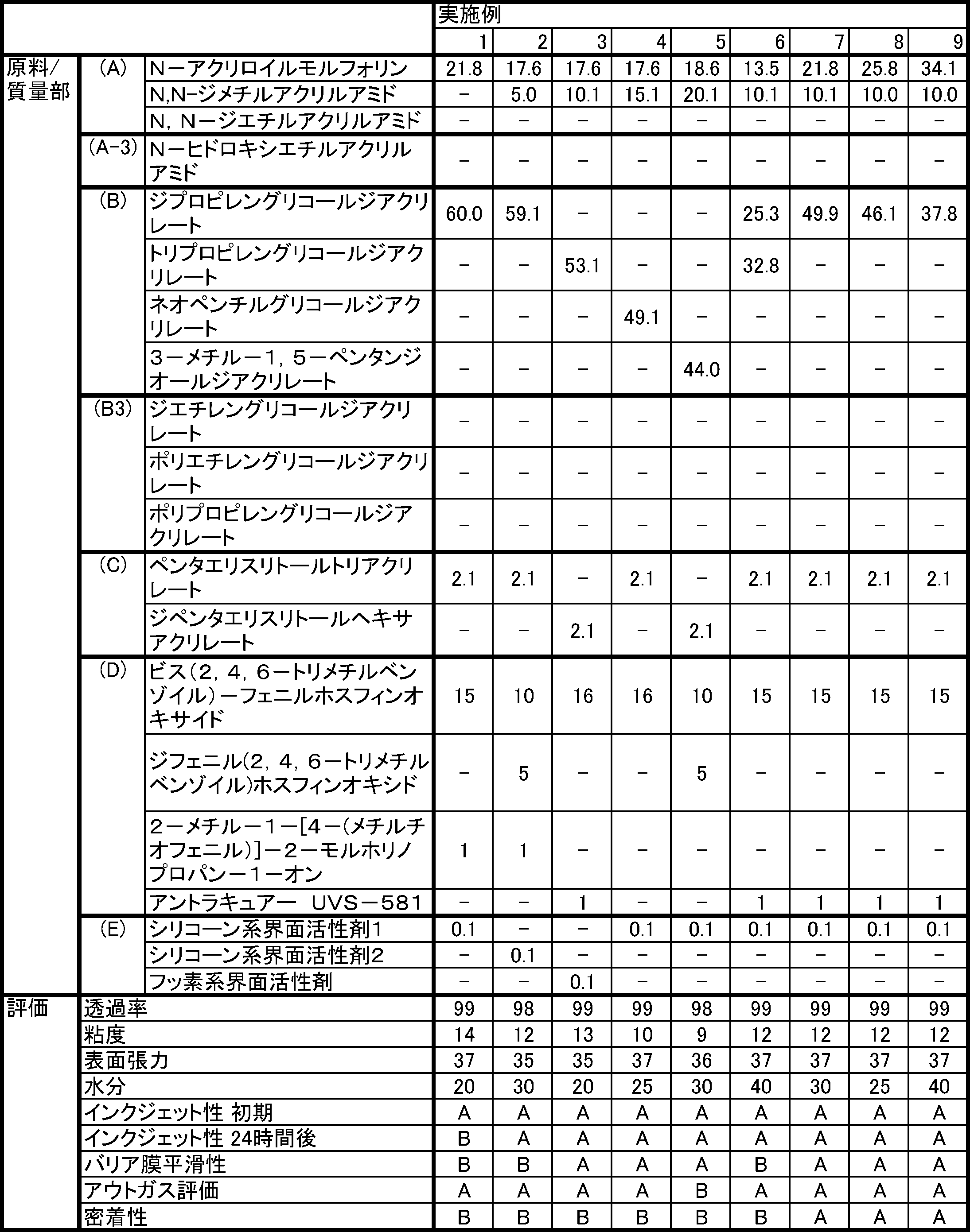
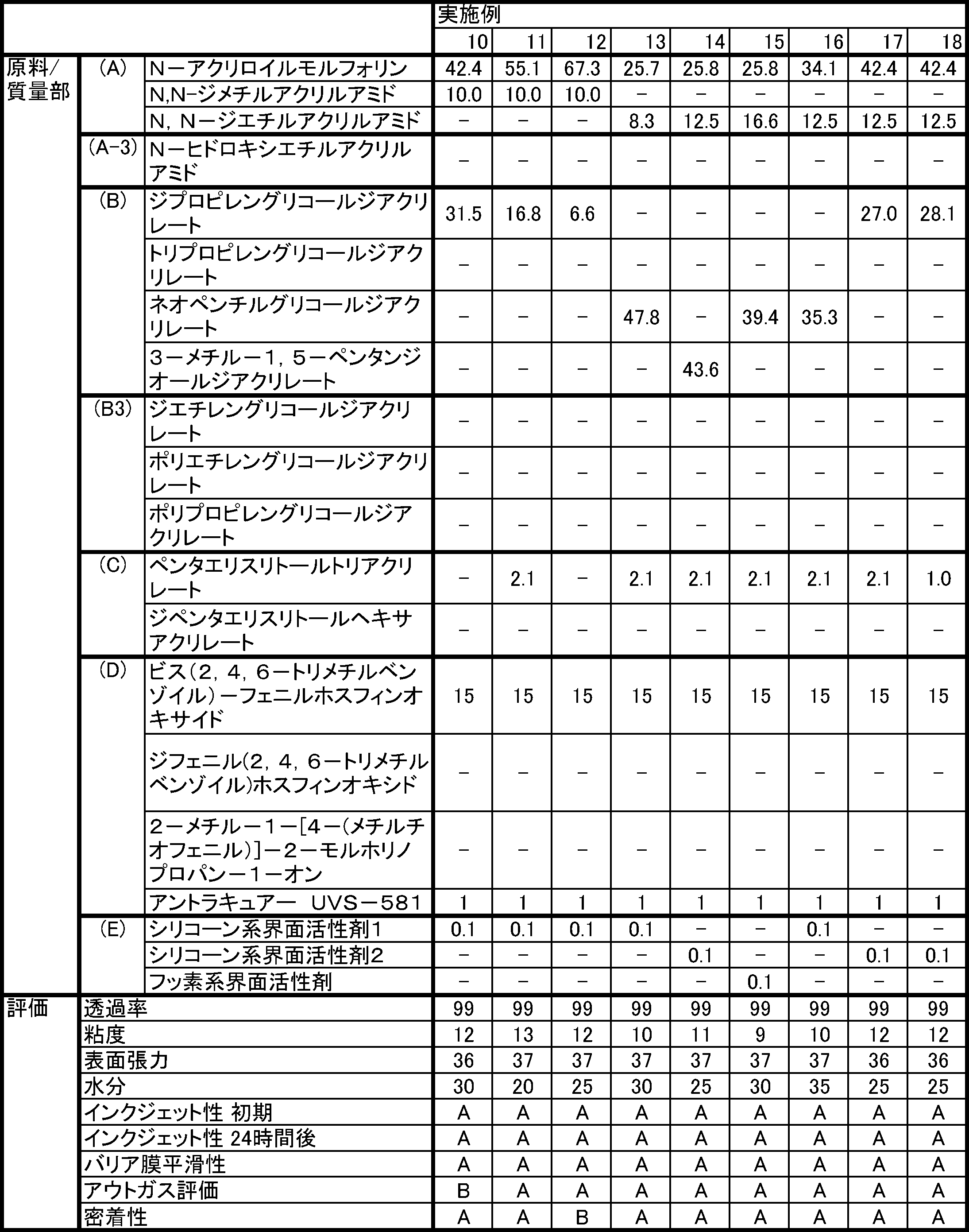
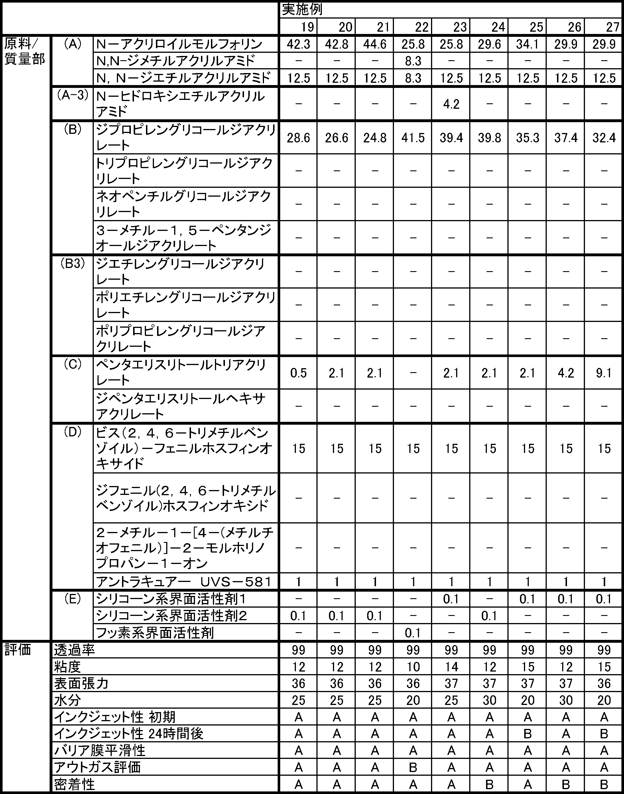
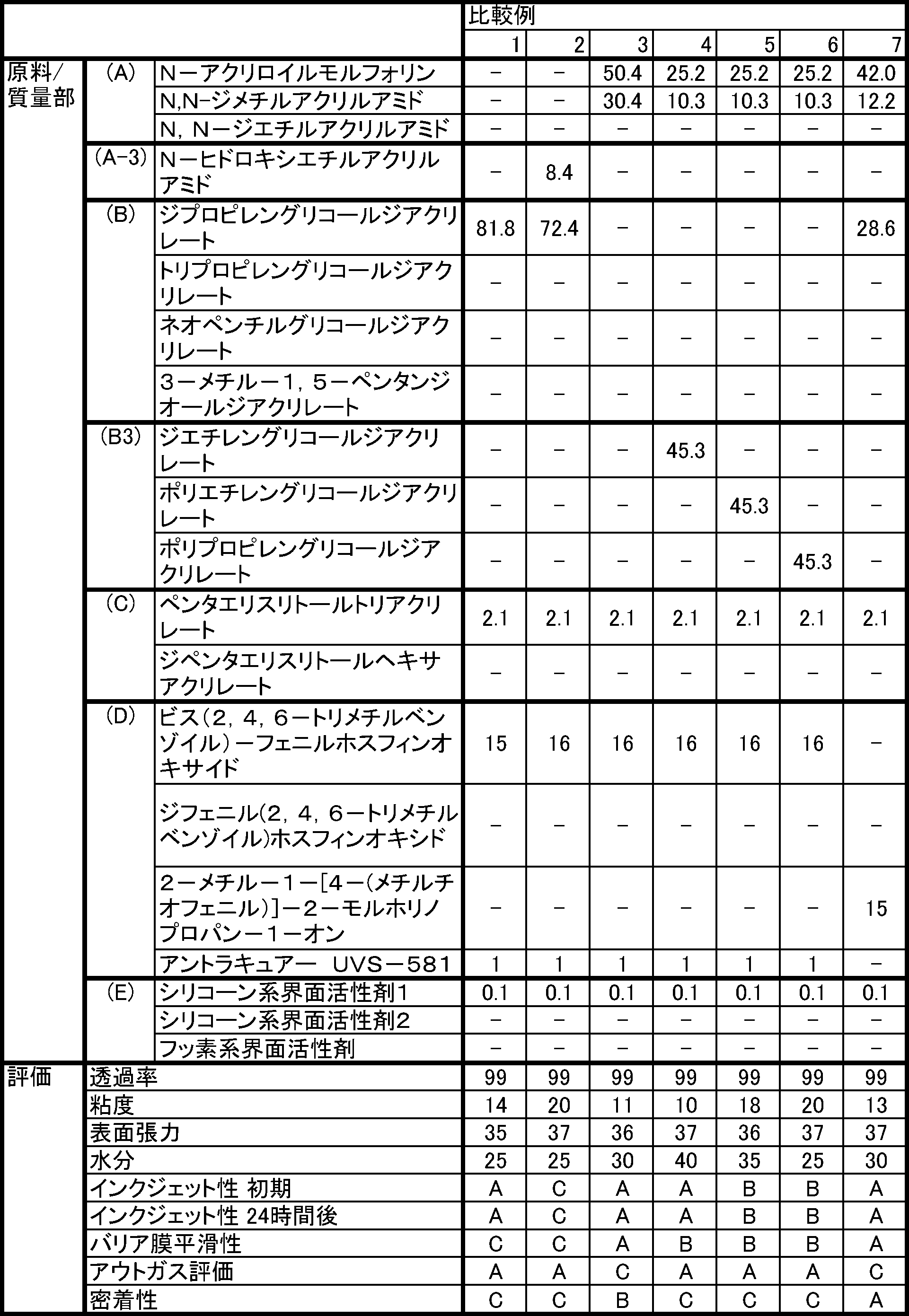
表の結果から、実施例1~27の組成物は、初期粘度が低く、インクジェット性及び平滑性に優れている。また、実施例1~27の組成物を硬化させた硬化物からはアウトガスが発生しにくく、かつ無機質材との密着性に優れる。一方、化合物(A)を含まない比較例1は無機質材との濡れ性が悪く、平滑性も悪く、また密着性も悪い。また化合物(A)以外のN-置換(メタ)アクリルアミド(A-3)しか含まない比較例2の組成物は比較例1同様、平滑性が悪く、また密着性も悪い。また比較例2は粘度が高くインクジェット性が悪いためインクジェット法に適さない。2官能の(メタ)アクリル化合物を全く含まない比較例3の組成物では封止材からアウトガスが発生しやすい。2官能(メタ)アクリル化合物(B3)を含むものの化合物(B)を含まない比較例4~6は、封止材の密着性が悪い。アシルフォスフィンオキサイド系開始剤を含まない比較例7では、封止材からアウトガスが発生しやすい。
Claims (12)
- N,N-ジメチルアクリルアミド、N,N-ジエチルアクリルアミド及びN-アクリロイルモルフォリンからなる群から選択される少なくとも一種からなる化合物(A)と;
下記一般式(1)で示される化合物(B)と、
CH2=CXCO-O-(R-O)n-COCX=CH2 (1)
nは1以上3以下の整数、Rは炭素数3以上6以下のアルキレン基、ただし1分子中にRが複数ある場合はRは各々独立に炭素数3以上6以下のアルキレン基、Xは各々独立に水素原子又はメチル基;
アシルフォスフィンオキサイド化合物を含有する光重合開始剤(D)と;を含有し、
25℃での粘度が1mPa・s以上40mPa・s以下と、40℃における粘度が1mPa・s以上40mPa・s以下とのうち、少なくとも一方を満たす、
紫外線硬化性樹脂組成物。 - 前記化合物(B)は、ジプロピレングリコールジアクリレート、トリプロピレングリコールジアクリレート、ネオペンチルグリコールジアクリレート及び3-メチル-1,5-ペンタンジオールジアクリレートからなる群から選択される少なくとも一種を含有する、
請求項1に記載の紫外線硬化性樹脂組成物。 - 前記化合物(A)が、少なくとも前記N,N-アクリロイルモルフォリンを含む、請求項1又は2に記載の紫外線硬化性樹脂組成物。
- 前記化合物(A)が、前記N,N-アクリロイルモルフォリンを含み、且つ前記N,N-ジメチルアクリルアミド及び前記N,N-ジエチルアクリルアミドのうちの少なくとも一種を含む、
請求項3に記載の紫外線硬化性樹脂組成物。 - 前記N,N-ジメチルアクリルアミドと前記N,N-ジエチルアクリルアミドの合計量の割合は、前記紫外線硬化性樹脂組成物全体に対して、5質量%以上20質量%以下である、
請求項4に記載の紫外線硬化性樹脂組成物。 - 前記N-アクリロイルモルフォリンの割合は、前記紫外線硬化性樹脂組成物全体に対して、5質量%以上60質量%以下である、
請求項3から5のいずれか一項に記載の紫外線硬化性樹脂組成物。 - 一分子中に3つ以上の(メタ)アクリロイル基を有する化合物(C)を更に含有する、
請求項1から6のいずれか一項に記載の紫外線硬化性樹脂組成物。 - 界面活性剤(E)を更に含有する、
請求項1から7のいずれか一項に記載の紫外線硬化性樹脂組成物。 - 前記界面活性剤(E)は、シリコーン系界面活性剤とフッ素系界面活性剤とのうち少なくとも一方を含有する、
請求項8に記載の紫外線硬化性樹脂組成物。 - 前期紫外線硬化性樹脂組成物の水分量が100ppm以下である、
請求項1から9のいずれか一項に記載の紫外線硬化性樹脂組成物。 - 発光素子と、前記発光素子を封止する封止材とを備え、前記封止材は、請求項1から10のいずれか一項に記載の紫外線硬化性樹脂組成物の硬化物を含む、
発光装置。 - 発光素子と、前記発光素子を封止する封止材とを備える発光装置を製造する方法であり、
請求項1から10のいずれか一項に記載の紫外線硬化性樹脂組成物をインクジェット法で塗布してから前記紫外線硬化性樹脂組成物に紫外線を照射することで硬化させて前記封止材を作製することを含む、
発光装置の製造方法。
Priority Applications (3)
| Application Number | Priority Date | Filing Date | Title |
|---|---|---|---|
| CN202180072960.7A CN116419934A (zh) | 2020-11-11 | 2021-11-11 | 紫外线固化性树脂组合物、发光装置和发光装置的制造方法 |
| KR1020237014189A KR20230104875A (ko) | 2020-11-11 | 2021-11-11 | 자외선 경화성 수지 조성물, 발광 장치 및 발광 장치의 제조 방법 |
| JP2022562179A JP7847351B2 (ja) | 2020-11-11 | 2021-11-11 | 紫外線硬化性樹脂組成物、発光装置及び発光装置の製造方法 |
Applications Claiming Priority (2)
| Application Number | Priority Date | Filing Date | Title |
|---|---|---|---|
| JP2020188204 | 2020-11-11 | ||
| JP2020-188204 | 2020-11-11 |
Publications (1)
| Publication Number | Publication Date |
|---|---|
| WO2022102716A1 true WO2022102716A1 (ja) | 2022-05-19 |
Family
ID=81601243
Family Applications (1)
| Application Number | Title | Priority Date | Filing Date |
|---|---|---|---|
| PCT/JP2021/041575 Ceased WO2022102716A1 (ja) | 2020-11-11 | 2021-11-11 | 紫外線硬化性樹脂組成物、発光装置及び発光装置の製造方法 |
Country Status (4)
| Country | Link |
|---|---|
| JP (1) | JP7847351B2 (ja) |
| KR (1) | KR20230104875A (ja) |
| CN (1) | CN116419934A (ja) |
| WO (1) | WO2022102716A1 (ja) |
Cited By (1)
| Publication number | Priority date | Publication date | Assignee | Title |
|---|---|---|---|---|
| WO2025154648A1 (ja) * | 2024-01-18 | 2025-07-24 | パナソニックIpマネジメント株式会社 | 光硬化性樹脂組成物、光学部品、光学部品の製造方法、発光装置及び発光装置の製造方法 |
Citations (5)
| Publication number | Priority date | Publication date | Assignee | Title |
|---|---|---|---|---|
| KR20160044877A (ko) * | 2014-10-16 | 2016-04-26 | 한국다이요잉크 주식회사 | 잉크젯용 경화성 수지 조성물, 이를 이용한 솔더레지스트 및 그 제조방법 |
| JP2016187874A (ja) * | 2015-03-30 | 2016-11-04 | 東洋インキScホールディングス株式会社 | 積層体の製造方法、およびそれに適した活性エネルギー線硬化性ワニス組成物 |
| WO2018164012A1 (ja) * | 2017-03-06 | 2018-09-13 | マクセルホールディングス株式会社 | モデル材インクセット、サポート材組成物、インクセット、立体造形物および立体造形物の製造方法 |
| WO2019176139A1 (ja) * | 2018-03-15 | 2019-09-19 | マクセルホールディングス株式会社 | モデル材用組成物、及び光造形用組成物セット |
| CN110467704A (zh) * | 2019-08-02 | 2019-11-19 | 济南赢科新材料科技有限公司 | 一种3d打印用led光固化柔性光敏树脂及其制备方法 |
Family Cites Families (5)
| Publication number | Priority date | Publication date | Assignee | Title |
|---|---|---|---|---|
| EP3186319A4 (en) | 2014-07-25 | 2018-04-18 | Kateeva, Inc. | Organic thin film ink compositions and methods |
| JP2019145369A (ja) * | 2018-02-22 | 2019-08-29 | 東洋インキScホールディングス株式会社 | ディスプレイ |
| JP7489608B2 (ja) * | 2019-07-18 | 2024-05-24 | パナソニックIpマネジメント株式会社 | 紫外線硬化性樹脂組成物、及び発光装置 |
| JP7825165B2 (ja) * | 2020-02-07 | 2026-03-06 | パナソニックIpマネジメント株式会社 | 紫外線硬化性樹脂組成物、光学部品、光学部品の製造方法、発光装置、及び発光装置の製造方法 |
| JP7752315B2 (ja) * | 2020-09-29 | 2025-10-10 | パナソニックIpマネジメント株式会社 | 紫外線硬化性樹脂組成物、光学部品、光学部品の製造方法、発光装置、及び発光装置の製造方法 |
-
2021
- 2021-11-11 JP JP2022562179A patent/JP7847351B2/ja active Active
- 2021-11-11 WO PCT/JP2021/041575 patent/WO2022102716A1/ja not_active Ceased
- 2021-11-11 KR KR1020237014189A patent/KR20230104875A/ko active Pending
- 2021-11-11 CN CN202180072960.7A patent/CN116419934A/zh active Pending
Patent Citations (5)
| Publication number | Priority date | Publication date | Assignee | Title |
|---|---|---|---|---|
| KR20160044877A (ko) * | 2014-10-16 | 2016-04-26 | 한국다이요잉크 주식회사 | 잉크젯용 경화성 수지 조성물, 이를 이용한 솔더레지스트 및 그 제조방법 |
| JP2016187874A (ja) * | 2015-03-30 | 2016-11-04 | 東洋インキScホールディングス株式会社 | 積層体の製造方法、およびそれに適した活性エネルギー線硬化性ワニス組成物 |
| WO2018164012A1 (ja) * | 2017-03-06 | 2018-09-13 | マクセルホールディングス株式会社 | モデル材インクセット、サポート材組成物、インクセット、立体造形物および立体造形物の製造方法 |
| WO2019176139A1 (ja) * | 2018-03-15 | 2019-09-19 | マクセルホールディングス株式会社 | モデル材用組成物、及び光造形用組成物セット |
| CN110467704A (zh) * | 2019-08-02 | 2019-11-19 | 济南赢科新材料科技有限公司 | 一种3d打印用led光固化柔性光敏树脂及其制备方法 |
Cited By (1)
| Publication number | Priority date | Publication date | Assignee | Title |
|---|---|---|---|---|
| WO2025154648A1 (ja) * | 2024-01-18 | 2025-07-24 | パナソニックIpマネジメント株式会社 | 光硬化性樹脂組成物、光学部品、光学部品の製造方法、発光装置及び発光装置の製造方法 |
Also Published As
| Publication number | Publication date |
|---|---|
| JP7847351B2 (ja) | 2026-04-17 |
| CN116419934A (zh) | 2023-07-11 |
| JPWO2022102716A1 (ja) | 2022-05-19 |
| KR20230104875A (ko) | 2023-07-11 |
Similar Documents
| Publication | Publication Date | Title |
|---|---|---|
| JP5846974B2 (ja) | 光インプリント用硬化性組成物、パターン形成方法およびパターン | |
| JP5895757B2 (ja) | 感光性組成物、成形物の製造方法、成形物および半導体装置 | |
| KR20230161968A (ko) | 광경화성 수지 조성물, 광학 부품, 광학 부품의 제조 방법, 및 발광 장치 | |
| WO2014208487A1 (ja) | インクジェット吐出方法、パターン形成方法、および、パターン | |
| JP7442121B2 (ja) | 紫外線硬化性樹脂組成物、カラーレジスト、カラーフィルタ、発光装置及びカラーレジストの製造方法 | |
| JP7627836B2 (ja) | 紫外線硬化性樹脂組成物、発光装置、及び発光装置の製造方法 | |
| WO2022102716A1 (ja) | 紫外線硬化性樹脂組成物、発光装置及び発光装置の製造方法 | |
| JP7611477B2 (ja) | 紫外線硬化性樹脂組成物、発光装置の製造方法、発光装置、及びタッチパネル | |
| JP7281663B2 (ja) | 紫外線硬化性樹脂組成物、有機el発光装置の製造方法及び有機el発光装置 | |
| JP7752315B2 (ja) | 紫外線硬化性樹脂組成物、光学部品、光学部品の製造方法、発光装置、及び発光装置の製造方法 | |
| WO2024202791A1 (ja) | ケイ素含有アクリル化合物、光硬化性樹脂組成物、光学部品、光学部品の製造方法、発光装置及び発光装置の製造方法 | |
| JP7599145B2 (ja) | 紫外線硬化性樹脂組成物、光学部品、光学部品の製造方法、発光装置、及び発光装置の製造方法 | |
| CN120265665A (zh) | 光固化性树脂组合物、光学部件、光学部件的制造方法、发光装置和发光装置的制造方法 | |
| JP7761574B2 (ja) | 表示素子用封止剤、その硬化物および表示装置 | |
| CN112578634A (zh) | 紫外线固化性树脂组合物、彩色滤光片、彩色抗蚀剂和发光装置及它们的制造方法 | |
| JP2023037594A (ja) | 紫外線硬化性樹脂組成物 | |
| WO2022050421A1 (ja) | インクジェット塗布用及びled保護用硬化性組成物、ledモジュール、ledモジュールの製造方法及びled表示装置 | |
| JP7825165B2 (ja) | 紫外線硬化性樹脂組成物、光学部品、光学部品の製造方法、発光装置、及び発光装置の製造方法 | |
| JP7474052B2 (ja) | 有機el表示素子用封止剤 | |
| KR20250112756A (ko) | 광경화성 수지 조성물, 광학 부품, 광학 부품의 제조 방법, 발광 장치 및 발광 장치의 제조 방법 | |
| KR20250166931A (ko) | 광경화성 수지 조성물, 광학 부품, 광학 부품의 제조 방법, 발광 장치 및 발광 장치의 제조 방법 | |
| JP2022093086A (ja) | 紫外線硬化性樹脂組成物、光学部品、光学部品の製造方法、発光装置、及び発光装置の製造方法 | |
| JP2024012375A (ja) | 硬化性樹脂組成物、硬化物、及び、有機el表示素子 | |
| JP2021123693A (ja) | 紫外線硬化性樹脂組成物、光学部品、光学部品の製造方法、発光装置、及び発光装置の製造方法 |
Legal Events
| Date | Code | Title | Description |
|---|---|---|---|
| 121 | Ep: the epo has been informed by wipo that ep was designated in this application |
Ref document number: 21891961 Country of ref document: EP Kind code of ref document: A1 |
|
| ENP | Entry into the national phase |
Ref document number: 2022562179 Country of ref document: JP Kind code of ref document: A |
|
| NENP | Non-entry into the national phase |
Ref country code: DE |
|
| 122 | Ep: pct application non-entry in european phase |
Ref document number: 21891961 Country of ref document: EP Kind code of ref document: A1 |