WO2022102335A1 - 多孔質メタルボンド砥石の製造方法および多孔質メタルボンドホイールの製造方法 - Google Patents
多孔質メタルボンド砥石の製造方法および多孔質メタルボンドホイールの製造方法 Download PDFInfo
- Publication number
- WO2022102335A1 WO2022102335A1 PCT/JP2021/038076 JP2021038076W WO2022102335A1 WO 2022102335 A1 WO2022102335 A1 WO 2022102335A1 JP 2021038076 W JP2021038076 W JP 2021038076W WO 2022102335 A1 WO2022102335 A1 WO 2022102335A1
- Authority
- WO
- WIPO (PCT)
- Prior art keywords
- porous metal
- metal bond
- pore
- forming material
- grindstone
- Prior art date
Links
- 229910052751 metal Inorganic materials 0.000 title claims abstract description 151
- 239000002184 metal Substances 0.000 title claims abstract description 151
- 238000004519 manufacturing process Methods 0.000 title claims abstract description 60
- 238000000034 method Methods 0.000 title claims abstract description 45
- 239000000463 material Substances 0.000 claims abstract description 113
- 239000011148 porous material Substances 0.000 claims abstract description 64
- 239000006061 abrasive grain Substances 0.000 claims abstract description 49
- 239000002904 solvent Substances 0.000 claims abstract description 40
- 238000010304 firing Methods 0.000 claims abstract description 22
- 239000000843 powder Substances 0.000 claims abstract description 17
- 238000000465 moulding Methods 0.000 claims abstract description 13
- 239000002245 particle Substances 0.000 claims description 32
- 239000010953 base metal Substances 0.000 claims description 16
- CSCPPACGZOOCGX-UHFFFAOYSA-N Acetone Chemical compound CC(C)=O CSCPPACGZOOCGX-UHFFFAOYSA-N 0.000 claims description 8
- XLYOFNOQVPJJNP-UHFFFAOYSA-N water Substances O XLYOFNOQVPJJNP-UHFFFAOYSA-N 0.000 claims description 8
- LFQSCWFLJHTTHZ-UHFFFAOYSA-N Ethanol Chemical compound CCO LFQSCWFLJHTTHZ-UHFFFAOYSA-N 0.000 claims description 6
- 229910017053 inorganic salt Inorganic materials 0.000 claims description 4
- 150000001875 compounds Chemical class 0.000 claims description 3
- 238000000227 grinding Methods 0.000 description 45
- 239000000047 product Substances 0.000 description 20
- 238000012360 testing method Methods 0.000 description 14
- 235000012431 wafers Nutrition 0.000 description 11
- 238000003754 machining Methods 0.000 description 8
- 239000000203 mixture Substances 0.000 description 7
- HBMJWWWQQXIZIP-UHFFFAOYSA-N silicon carbide Chemical compound [Si+]#[C-] HBMJWWWQQXIZIP-UHFFFAOYSA-N 0.000 description 7
- 239000011230 binding agent Substances 0.000 description 6
- 239000002131 composite material Substances 0.000 description 6
- 238000009826 distribution Methods 0.000 description 5
- 239000010419 fine particle Substances 0.000 description 5
- 238000012545 processing Methods 0.000 description 5
- 229910052594 sapphire Inorganic materials 0.000 description 5
- 239000010980 sapphire Substances 0.000 description 5
- XEEYBQQBJWHFJM-UHFFFAOYSA-N Iron Chemical compound [Fe] XEEYBQQBJWHFJM-UHFFFAOYSA-N 0.000 description 4
- 239000010949 copper Substances 0.000 description 4
- 238000010586 diagram Methods 0.000 description 4
- 239000012466 permeate Substances 0.000 description 4
- 238000005498 polishing Methods 0.000 description 4
- 239000000758 substrate Substances 0.000 description 4
- RYGMFSIKBFXOCR-UHFFFAOYSA-N Copper Chemical compound [Cu] RYGMFSIKBFXOCR-UHFFFAOYSA-N 0.000 description 3
- OKKJLVBELUTLKV-UHFFFAOYSA-N Methanol Chemical compound OC OKKJLVBELUTLKV-UHFFFAOYSA-N 0.000 description 3
- ATJFFYVFTNAWJD-UHFFFAOYSA-N Tin Chemical compound [Sn] ATJFFYVFTNAWJD-UHFFFAOYSA-N 0.000 description 3
- 229910052802 copper Inorganic materials 0.000 description 3
- 229910003460 diamond Inorganic materials 0.000 description 3
- 239000010432 diamond Substances 0.000 description 3
- 238000002156 mixing Methods 0.000 description 3
- 238000003825 pressing Methods 0.000 description 3
- 229910052718 tin Inorganic materials 0.000 description 3
- 239000011135 tin Substances 0.000 description 3
- TWRXJAOTZQYOKJ-UHFFFAOYSA-L Magnesium chloride Chemical compound [Mg+2].[Cl-].[Cl-] TWRXJAOTZQYOKJ-UHFFFAOYSA-L 0.000 description 2
- CSNNHWWHGAXBCP-UHFFFAOYSA-L Magnesium sulfate Chemical compound [Mg+2].[O-][S+2]([O-])([O-])[O-] CSNNHWWHGAXBCP-UHFFFAOYSA-L 0.000 description 2
- PXHVJJICTQNCMI-UHFFFAOYSA-N Nickel Chemical compound [Ni] PXHVJJICTQNCMI-UHFFFAOYSA-N 0.000 description 2
- WCUXLLCKKVVCTQ-UHFFFAOYSA-M Potassium chloride Chemical compound [Cl-].[K+] WCUXLLCKKVVCTQ-UHFFFAOYSA-M 0.000 description 2
- CDBYLPFSWZWCQE-UHFFFAOYSA-L Sodium Carbonate Chemical compound [Na+].[Na+].[O-]C([O-])=O CDBYLPFSWZWCQE-UHFFFAOYSA-L 0.000 description 2
- PMZURENOXWZQFD-UHFFFAOYSA-L Sodium Sulfate Chemical compound [Na+].[Na+].[O-]S([O-])(=O)=O PMZURENOXWZQFD-UHFFFAOYSA-L 0.000 description 2
- FAPWRFPIFSIZLT-UHFFFAOYSA-M Sodium chloride Chemical compound [Na+].[Cl-] FAPWRFPIFSIZLT-UHFFFAOYSA-M 0.000 description 2
- 229910052782 aluminium Inorganic materials 0.000 description 2
- XAGFODPZIPBFFR-UHFFFAOYSA-N aluminium Chemical compound [Al] XAGFODPZIPBFFR-UHFFFAOYSA-N 0.000 description 2
- 238000004458 analytical method Methods 0.000 description 2
- 238000009835 boiling Methods 0.000 description 2
- 238000001816 cooling Methods 0.000 description 2
- 238000005520 cutting process Methods 0.000 description 2
- 238000010438 heat treatment Methods 0.000 description 2
- 229910052742 iron Inorganic materials 0.000 description 2
- 238000007561 laser diffraction method Methods 0.000 description 2
- 239000007788 liquid Substances 0.000 description 2
- 230000000717 retained effect Effects 0.000 description 2
- 238000000790 scattering method Methods 0.000 description 2
- 235000002639 sodium chloride Nutrition 0.000 description 2
- 229910052938 sodium sulfate Inorganic materials 0.000 description 2
- 235000011152 sodium sulphate Nutrition 0.000 description 2
- 238000012935 Averaging Methods 0.000 description 1
- UXVMQQNJUSDDNG-UHFFFAOYSA-L Calcium chloride Chemical compound [Cl-].[Cl-].[Ca+2] UXVMQQNJUSDDNG-UHFFFAOYSA-L 0.000 description 1
- BQCADISMDOOEFD-UHFFFAOYSA-N Silver Chemical compound [Ag] BQCADISMDOOEFD-UHFFFAOYSA-N 0.000 description 1
- 239000004115 Sodium Silicate Substances 0.000 description 1
- RTAQQCXQSZGOHL-UHFFFAOYSA-N Titanium Chemical compound [Ti] RTAQQCXQSZGOHL-UHFFFAOYSA-N 0.000 description 1
- HCHKCACWOHOZIP-UHFFFAOYSA-N Zinc Chemical compound [Zn] HCHKCACWOHOZIP-UHFFFAOYSA-N 0.000 description 1
- QCWXUUIWCKQGHC-UHFFFAOYSA-N Zirconium Chemical compound [Zr] QCWXUUIWCKQGHC-UHFFFAOYSA-N 0.000 description 1
- 238000005299 abrasion Methods 0.000 description 1
- 239000000853 adhesive Substances 0.000 description 1
- 230000001070 adhesive effect Effects 0.000 description 1
- 229910045601 alloy Inorganic materials 0.000 description 1
- 239000000956 alloy Substances 0.000 description 1
- 239000001110 calcium chloride Substances 0.000 description 1
- 229910001628 calcium chloride Inorganic materials 0.000 description 1
- 235000011148 calcium chloride Nutrition 0.000 description 1
- 238000011088 calibration curve Methods 0.000 description 1
- 239000010941 cobalt Substances 0.000 description 1
- 229910017052 cobalt Inorganic materials 0.000 description 1
- GUTLYIVDDKVIGB-UHFFFAOYSA-N cobalt atom Chemical compound [Co] GUTLYIVDDKVIGB-UHFFFAOYSA-N 0.000 description 1
- 239000000470 constituent Substances 0.000 description 1
- 238000011109 contamination Methods 0.000 description 1
- 238000007796 conventional method Methods 0.000 description 1
- 230000006866 deterioration Effects 0.000 description 1
- 238000002149 energy-dispersive X-ray emission spectroscopy Methods 0.000 description 1
- PCHJSUWPFVWCPO-UHFFFAOYSA-N gold Chemical group [Au] PCHJSUWPFVWCPO-UHFFFAOYSA-N 0.000 description 1
- 229910052737 gold Inorganic materials 0.000 description 1
- 239000010931 gold Substances 0.000 description 1
- 239000012535 impurity Substances 0.000 description 1
- 229910001629 magnesium chloride Inorganic materials 0.000 description 1
- 235000011147 magnesium chloride Nutrition 0.000 description 1
- 229910052943 magnesium sulfate Inorganic materials 0.000 description 1
- 235000019341 magnesium sulphate Nutrition 0.000 description 1
- 239000011159 matrix material Substances 0.000 description 1
- 238000002844 melting Methods 0.000 description 1
- 230000008018 melting Effects 0.000 description 1
- 239000011812 mixed powder Substances 0.000 description 1
- 229910021421 monocrystalline silicon Inorganic materials 0.000 description 1
- 229910052759 nickel Inorganic materials 0.000 description 1
- 230000002093 peripheral effect Effects 0.000 description 1
- 230000035699 permeability Effects 0.000 description 1
- 230000000704 physical effect Effects 0.000 description 1
- 239000001103 potassium chloride Substances 0.000 description 1
- 235000011164 potassium chloride Nutrition 0.000 description 1
- OTYBMLCTZGSZBG-UHFFFAOYSA-L potassium sulfate Chemical compound [K+].[K+].[O-]S([O-])(=O)=O OTYBMLCTZGSZBG-UHFFFAOYSA-L 0.000 description 1
- 229910052939 potassium sulfate Inorganic materials 0.000 description 1
- 235000011151 potassium sulphates Nutrition 0.000 description 1
- 238000011160 research Methods 0.000 description 1
- 150000003839 salts Chemical class 0.000 description 1
- 238000001878 scanning electron micrograph Methods 0.000 description 1
- 229910010271 silicon carbide Inorganic materials 0.000 description 1
- 229910052709 silver Inorganic materials 0.000 description 1
- 239000004332 silver Substances 0.000 description 1
- 229910000029 sodium carbonate Inorganic materials 0.000 description 1
- 235000017550 sodium carbonate Nutrition 0.000 description 1
- 239000011780 sodium chloride Substances 0.000 description 1
- NTHWMYGWWRZVTN-UHFFFAOYSA-N sodium silicate Chemical compound [Na+].[Na+].[O-][Si]([O-])=O NTHWMYGWWRZVTN-UHFFFAOYSA-N 0.000 description 1
- 229910052911 sodium silicate Inorganic materials 0.000 description 1
- 235000019794 sodium silicate Nutrition 0.000 description 1
- 239000002344 surface layer Substances 0.000 description 1
- 239000010936 titanium Substances 0.000 description 1
- 229910052719 titanium Inorganic materials 0.000 description 1
- WFKWXMTUELFFGS-UHFFFAOYSA-N tungsten Chemical compound [W] WFKWXMTUELFFGS-UHFFFAOYSA-N 0.000 description 1
- 229910052721 tungsten Inorganic materials 0.000 description 1
- 239000010937 tungsten Substances 0.000 description 1
- 238000009834 vaporization Methods 0.000 description 1
- 230000008016 vaporization Effects 0.000 description 1
- 238000009423 ventilation Methods 0.000 description 1
- 229910052725 zinc Inorganic materials 0.000 description 1
- 239000011701 zinc Substances 0.000 description 1
- 229910052726 zirconium Inorganic materials 0.000 description 1
Images


Classifications
-
- B—PERFORMING OPERATIONS; TRANSPORTING
- B24—GRINDING; POLISHING
- B24D—TOOLS FOR GRINDING, BUFFING OR SHARPENING
- B24D3/00—Physical features of abrasive bodies, or sheets, e.g. abrasive surfaces of special nature; Abrasive bodies or sheets characterised by their constituents
- B24D3/02—Physical features of abrasive bodies, or sheets, e.g. abrasive surfaces of special nature; Abrasive bodies or sheets characterised by their constituents the constituent being used as bonding agent
- B24D3/04—Physical features of abrasive bodies, or sheets, e.g. abrasive surfaces of special nature; Abrasive bodies or sheets characterised by their constituents the constituent being used as bonding agent and being essentially inorganic
- B24D3/06—Physical features of abrasive bodies, or sheets, e.g. abrasive surfaces of special nature; Abrasive bodies or sheets characterised by their constituents the constituent being used as bonding agent and being essentially inorganic metallic or mixture of metals with ceramic materials, e.g. hard metals, "cermets", cements
- B24D3/10—Physical features of abrasive bodies, or sheets, e.g. abrasive surfaces of special nature; Abrasive bodies or sheets characterised by their constituents the constituent being used as bonding agent and being essentially inorganic metallic or mixture of metals with ceramic materials, e.g. hard metals, "cermets", cements for porous or cellular structure, e.g. for use with diamonds as abrasives
-
- B—PERFORMING OPERATIONS; TRANSPORTING
- B24—GRINDING; POLISHING
- B24D—TOOLS FOR GRINDING, BUFFING OR SHARPENING
- B24D18/00—Manufacture of grinding tools or other grinding devices, e.g. wheels, not otherwise provided for
-
- B—PERFORMING OPERATIONS; TRANSPORTING
- B24—GRINDING; POLISHING
- B24D—TOOLS FOR GRINDING, BUFFING OR SHARPENING
- B24D18/00—Manufacture of grinding tools or other grinding devices, e.g. wheels, not otherwise provided for
- B24D18/0009—Manufacture of grinding tools or other grinding devices, e.g. wheels, not otherwise provided for using moulds or presses
-
- B—PERFORMING OPERATIONS; TRANSPORTING
- B24—GRINDING; POLISHING
- B24D—TOOLS FOR GRINDING, BUFFING OR SHARPENING
- B24D3/00—Physical features of abrasive bodies, or sheets, e.g. abrasive surfaces of special nature; Abrasive bodies or sheets characterised by their constituents
-
- B—PERFORMING OPERATIONS; TRANSPORTING
- B24—GRINDING; POLISHING
- B24D—TOOLS FOR GRINDING, BUFFING OR SHARPENING
- B24D3/00—Physical features of abrasive bodies, or sheets, e.g. abrasive surfaces of special nature; Abrasive bodies or sheets characterised by their constituents
- B24D3/02—Physical features of abrasive bodies, or sheets, e.g. abrasive surfaces of special nature; Abrasive bodies or sheets characterised by their constituents the constituent being used as bonding agent
- B24D3/04—Physical features of abrasive bodies, or sheets, e.g. abrasive surfaces of special nature; Abrasive bodies or sheets characterised by their constituents the constituent being used as bonding agent and being essentially inorganic
- B24D3/06—Physical features of abrasive bodies, or sheets, e.g. abrasive surfaces of special nature; Abrasive bodies or sheets characterised by their constituents the constituent being used as bonding agent and being essentially inorganic metallic or mixture of metals with ceramic materials, e.g. hard metals, "cermets", cements
-
- B—PERFORMING OPERATIONS; TRANSPORTING
- B24—GRINDING; POLISHING
- B24D—TOOLS FOR GRINDING, BUFFING OR SHARPENING
- B24D3/00—Physical features of abrasive bodies, or sheets, e.g. abrasive surfaces of special nature; Abrasive bodies or sheets characterised by their constituents
- B24D3/02—Physical features of abrasive bodies, or sheets, e.g. abrasive surfaces of special nature; Abrasive bodies or sheets characterised by their constituents the constituent being used as bonding agent
- B24D3/04—Physical features of abrasive bodies, or sheets, e.g. abrasive surfaces of special nature; Abrasive bodies or sheets characterised by their constituents the constituent being used as bonding agent and being essentially inorganic
- B24D3/14—Physical features of abrasive bodies, or sheets, e.g. abrasive surfaces of special nature; Abrasive bodies or sheets characterised by their constituents the constituent being used as bonding agent and being essentially inorganic ceramic, i.e. vitrified bondings
- B24D3/18—Physical features of abrasive bodies, or sheets, e.g. abrasive surfaces of special nature; Abrasive bodies or sheets characterised by their constituents the constituent being used as bonding agent and being essentially inorganic ceramic, i.e. vitrified bondings for porous or cellular structure
Definitions
- the present invention relates to a method for manufacturing a porous metal bond grindstone.
- the present invention also relates to a method for manufacturing a porous metal bond wheel.
- a vitrified bond grindstone has been conventionally used as a suitable grinding wheel for grinding high hardness and brittle materials with stable grinding ability, high efficiency and long life.
- there was not much demand for grinding of high hardness and brittle materials and it was sufficient to take time.
- there is an increasing demand for high efficiency and long life machining for the purpose of improving productivity and reducing machining costs, and a grindstone to achieve these is required. Has been done.
- Porous metal bond grindstones are sometimes used as tools with excellent life in the high efficiency, high precision machining field of such high hardness and brittle materials and the finishing machining field called super finishing.
- a method for producing a porous metal bond grindstone a method of adding a closed cell material such as hollow fine particles to form pores, a method of adding an organic medium and forming pores by burning through by firing, and a method of adding salt and firing after firing. A method of eluting into a solvent to form pores is known.
- Patent Document 1 discloses a perforated grindstone characterized in that abrasive grains and inorganic hollow fine particles are dispersed in a metal binder or a vitreous binder. Further, it is disclosed that a perforated grindstone can be manufactured by heating a mixed powder obtained by mixing abrasive grains, hollow fine particles, and a powder of a metal binder, melting the metal binder, and then cooling the mixture.
- Patent Document 2 is a composite material for polishing a work piece of a hard material to obtain a desired surface finish, and has a specific abrasive grain, a specific metal bonding material, and a specific ratio of pores.
- a composite material and a method for producing the composite material are disclosed, and it is described that a polishing article is immersed in a solvent to leach out a dispersoid, thereby leaving continuous pores in the polishing article.
- Patent Document 3 describes (a) a mixture containing about 0.5 to about 25% by volume of abrasive grains, about 19.5 to about 49.5% by volume of a binder, and about 50 to about 80% by volume of dispersoid particles. (B) Pressing the mixture into a composite material filled with an abrasive, (c) heat-treating the composite material, (d) substantially all of the dispersoid particles. The composite material is immersed in a solvent that dissolves the dispersoid particles for a period of time suitable for dissolving the abrasive grains and the binder is substantially insoluble in the solvent. A method for manufacturing a polishing product having at least 50% by volume of continuous ventilation holes is disclosed.
- the porosity can be adjusted by the amount of the closed cell material added.
- the outer shell of the pores remains as an unnecessary residue, when used as a tool, there is a concern that this residue will come into contact with the work during machining, resulting in grinding burns and deterioration of machining accuracy due to an increase in resistance.
- a desolubilization step is performed after the firing step.
- a fired body in which the abrasive grains are firmly adhered to the metal bond is obtained, and even when immersed in a solvent, the decrease in the strength of the metal bond and the decrease in the adhesive force of the abrasive grains are suppressed, and the pore forming material is suppressed. It is considered possible to elute.
- the metal bond is firmly baked and hardened, it is necessary for the pore-forming material to communicate with the metal bond in order for the solvent to permeate. If the proportion of the pore-forming material in the fired body is too low, a portion where the pore-forming material does not communicate is formed, the solvent cannot permeate, and it becomes difficult to elute the pore-forming material. It is necessary for the pores to communicate with each other in order to eliminate all the dispersoids. For example, in the methods of Patent Document 2 and Patent Document 3, it is necessary to add at least 40% by volume or more of the dispersoid.
- the present invention has been made in view of the above circumstances, and an object of the present invention is to use a pore-forming material that can be eluted with a solvent, and the porosity can be arbitrarily adjusted from a low porosity to a high porosity. It is an object of the present invention to provide a method for manufacturing a porous metal bond grindstone and a method for manufacturing a porous metal bond wheel using the same.
- ⁇ 2> The method for producing a porous metal bond grindstone according to ⁇ 1>, wherein the volume ratio of the pore-forming material to the unfired molded product is 5 to 90% by volume.
- ⁇ 3> The method for producing a porous metal bond grindstone according to ⁇ 1> or ⁇ 2>, wherein the pore-forming material has an average particle size of 5 to 250 ⁇ m.
- ⁇ 4> The method for producing a porous metal bond grindstone according to any one of ⁇ 1> to ⁇ 3>, wherein the solvent contains one or more selected from the group consisting of water, alcohol and acetone.
- ⁇ 5> The method for producing a porous metal bond grindstone according to any one of ⁇ 1> to ⁇ 4>, wherein the solvent contains water and the pore-forming material is a water-soluble compound.
- ⁇ 6> The method for producing a porous metal bond grindstone according to ⁇ 5>, wherein the pore-forming material is a water-soluble inorganic salt.
- ⁇ 7> The step of adhering the porous metal bond grindstone manufactured by the method for manufacturing the porous metal bond grindstone according to any one of ⁇ 1> to ⁇ 4> to the base metal, and the base using a dresser.
- a method for producing a porous metal bond grindstone in which a porosity can be arbitrarily adjusted from a low porosity to a high porosity using a pore-forming material that can be eluted with a solvent.
- a porous metal bond grindstone in which the influence of unnecessary residues such as the outer shell of the closed cell material is suppressed can be obtained with a desired porosity.
- a method of manufacturing a porous metal bond wheel comprising a porous metal bond grindstone having an arbitrary porosity from low porosity to high porosity.
- the present invention comprises a molding step of obtaining an unfired molded body containing abrasive grains, a metal powder, and a pore-forming material, a vapor of a solvent having solubility in the pore-forming material, and the unfired molded body.
- a porous metal bond grindstone having a decalcification step of removing the pore-forming material to obtain an unfired molded body containing pores and a firing step of firing the unfired molded body containing the pores. It relates to a manufacturing method (hereinafter, may be referred to as "a method for manufacturing a grindstone of the present invention").
- the method for producing a grindstone of the present invention is characterized in that the pore-forming material is removed in a state where the molded body is not fired, and steam is used for removing the pore-forming material.
- the molded body is not firmly baked and hardened, so that the solvent can be used. It becomes easier for steam to penetrate into the interior. Therefore, even when the amount of the pore-forming material is small, the vapor of the solvent can permeate into the inside of the molded body, and the pore-forming material can be sufficiently eluted.
- the molded product is brought into contact with the vapor of the solvent instead of being immersed in the solvent, it becomes easier to penetrate into the inside of the molded product. Further, since the unfired molded product has low shape stability, if it is immersed in a solvent, the shape may be deformed. Even if there is, the shape of the molded body does not easily collapse. By firing the unfired molded body in which the pores are formed in this way, the metal powder is melted and fired while the pores are retained, and even with a low porosity, the pore-forming material is sufficiently removed. A grindstone can be made.
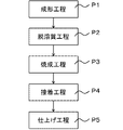
- FIG. 1 is a process diagram of a method for manufacturing a porous metal bond grindstone of the present invention. Hereinafter, each step will be described with reference to FIG.
- the molding step is a step of obtaining an unfired molded product containing the abrasive grains, the metal powder, and the pore-forming material.
- abrasive grains diamond or the like can be used.
- the average particle size of the abrasive grains can be appropriately selected depending on the type of grinding material and the like. When grinding a high-hardness brittle material such as silicon carbide or sapphire, if the abrasive grains bite deeply, the damage reaches the inside of the high-hardness brittle material, and the processing time in the next process becomes long. If the average particle size of the abrasive grains is too large, the abrasive grains deeply bite into the grinding material, and the damage to the grinding material tends to increase.
- the average particle size of the abrasive grains is preferably 4 to 55 ⁇ m.
- the thickness can be 12 to 55 ⁇ m.
- SiC silicon carbide
- the average particle size is the median diameter of the particle size distribution measured by a particle size distribution measuring device (laser diffraction and scattering method).
- the median diameter is a volume-based D50 value measured using a laser diffraction / scattering particle size distribution measuring device (LA-960) manufactured by HORIBA, Ltd. by a measuring method according to JIS Z 8825: 2013. Is.
- Metal powder As the metal powder, one or more selected from the group consisting of copper, tin, cobalt, iron, nickel, tungsten, silver, zinc, aluminum, titanium, zirconium, and alloys thereof can be used. In general, the metal powder preferably contains a mixture of copper and tin. For example, for grinding a high hardness brittle material, a composition containing about 30% by mass to about 70% by mass of copper and about 30% by mass to about 70% by mass of tin is preferable.
- the pore-forming material any solute particles that can be easily dissolved in a solvent such as water, alcohol (methanol, ethanol, etc.), acetone, etc. can be used.
- the pore-forming material is preferably a water-soluble compound, and more preferably a water-soluble inorganic salt.
- the water-soluble inorganic salt for example, one or more selected from the group consisting of sodium chloride, potassium chloride, magnesium chloride, calcium chloride, sodium silicate, sodium carbonate, sodium sulfate, potassium sulfate and magnesium sulfate is preferable.
- the average particle size of the pore forming material can be, for example, 5 to 300 ⁇ m. Since the size of the pores of the porous metal bond grindstone obtained by the method for producing the grindstone of the present invention corresponds to the size of the pore-forming material, the pores formed by adjusting the particle size of the pore-forming material are formed. The size can be adjusted. Further, the size of the pore forming material can be appropriately selected and used in consideration of ease of removal in the next step and the like. If the average particle size of the pore-forming material is too small, it becomes difficult for the vapor of the solvent to permeate, and the pore-forming material may remain inside the molded body.
- the lower limit of the average particle size is preferably 5 ⁇ m or more, and may be 10 ⁇ m or more, 50 ⁇ m or more, or 80 ⁇ m or more.
- the upper limit of the average particle size is preferably 250 ⁇ m or less, and may be 200 ⁇ m or less or 100 ⁇ m or less.
- the average particle size of the pores of the target porous metal bond grindstone is appropriately selected depending on the size of the abrasive grains and the type of the material to be studied. For example, diamond abrasive grains having an average particle size of 8 ⁇ m are used.
- the average particle size of the pore-forming material is preferably 70 to 200 ⁇ m.
- the average particle size of the pore-forming material is the median diameter of the particle size distribution measured by the particle size distribution measuring device (laser diffraction and scattering method).
- the porous metal bond grindstone obtained by the method for manufacturing a grindstone of the present invention is a metal bond having pores
- the number of abrasive grains in the portion excluding the pores from the grindstone surface is not the general concentration. Adjust the sharpness and wear resistance.
- the abrasive grains, the metal powder, and the pore forming material are preferably mixed so that the number of abrasive grains in the substrate portion excluding the pores from the ground surface is 700 to 6500 pieces / cm 2 .
- the grindstone becomes a porous metal bond grindstone with a large amount of metal bond per abrasive grain, which tends to hinder the replacement of worn abrasive grains and makes it difficult to continue processing. It tends to be. If the number of abrasive grains in the substrate portion is too large, the load per abrasive grain becomes small and the bite to the high hardness brittle material tends to be poor.
- the number of abrasive grains in the base portion excluding the pores from the ground surface can be calculated from the shape of the porous metal bond grindstone to be manufactured and the mixing ratio of the abrasive grains, the metal powder and the pore forming material.
- counting the number of abrasive grains from the obtained porous metal bond grindstone after performing binarization treatment on a magnified image 500 times the ground surface excluding the pores of the target porous metal bond grindstone, It is obtained by counting the number of abrasive grains per unit area (cm 2 ).
- the unfired molded product is predetermined by mixing abrasive grains, metal powder, and a pore-forming material, filling it in a predetermined molding die, and pressing (for example, pressing at 500 to 5000 kg / cm 2 ). It is molded into the shape of.
- the volume ratio of the pore-forming material in the unfired molded body (volume of the pore-forming material / volume of the unfired molded body ⁇ 100 (%)) is preferably 5 to 90% by volume. If the volume ratio of the pore-forming material in the unfired molded body is smaller than 5% by volume, the grindstone has many metal bonds (fewer pores). It may not be suitable for grinding. If it is larger than 90% by volume, the grindstone has a small amount of metal bonds that hold the abrasive grains, so that it becomes difficult to maintain the structure.
- the porosity of the obtained porous metal bond grindstone corresponds to the amount of pore-forming material in the unfired molded body, the porosity can be arbitrarily adjusted from low porosity to high porosity by adjusting the amount of porosity-forming material. Porosity can be adjusted.
- the volume ratio of the pore-forming material in the unfired molded product is preferably 5% by volume or more, and may be 10% by volume or more.
- the volume ratio of the pore-forming material in the unfired molded body is preferably 90% by volume or less, and may be 85% by volume or less, 80% by volume or less, 75% by volume or less, 70% by volume or less, and 65% by volume or less. ..
- the volume ratio of the pore-forming material in the unfired molded body is 5 to 35% by volume or 10 to 30% by volume. May be.
- the desolubilization step is a step of bringing the vapor of a solvent soluble in the pore-forming material into contact with the unfired molded product to remove the pore-forming material and obtain an unfired molded product containing pores.
- the unfired compact is usually taken out of the molding die and brought into contact with the vapor of the solvent that dissolves the pore-forming material.
- the pore-forming material in the unfired molded product can be efficiently removed, and pores can be formed in the portion where the pore-forming material is present.
- a method of contacting the vapor of the solvent having solubility in the pore forming material with the unfired molded body a method of heating the solvent to a boiling point or higher and supplying the generated vapor to the unfired molded body or , A method of introducing an unfired molded product into a treated portion filled with solvent vapor and the like.
- the steam generated from the steam generator can be supplied to the unfired molded product, or a humidifying furnace can be used.
- the contact may be carried out under pressure or reduced pressure.
- the solvent to be brought into contact with the unfired molded body as vapor may be any solvent as long as it is soluble in the pore-forming material (those having solubility in the pore-forming material), and can be appropriately selected depending on the type of the pore-forming material. .. In consideration of ease of handling, ease of vaporization, and the like, it is preferable to use a vapor of a solvent containing one or more selected from the group consisting of water, alcohol, and acetone. It is more preferable to use vapor of a solvent containing water.
- the temperature of the vapor of the solvent is preferably above the boiling point of the solvent to be used and below the firing temperature in the firing step, and is appropriately set depending on the type of solvent and the like.
- the temperature can be 100 to 200 ° C.
- the time for contacting the vapor of the solvent with the unfired molded body may be longer than the time during which the pore-forming material can disappear, and is appropriately set according to the type of the pore-forming material and the ratio in the unfired molded body. Is. For example, it can be 12 to 120 hours or 24 to 72 hours.
- the firing step is a step of firing an unfired molded product containing pores.
- the firing step may be performed by a known method.
- the formed pores were retained by heat-treating the unfired molded body containing the pores after the desolubilization step in a firing furnace having a firing temperature preset at 200 to 900 ° C. under reduced pressure or normal pressure.
- the metal powders are melt-bonded to each other to form a metal bond.
- a porous fired body can be obtained.
- FIG. 2 is a partial cross-sectional schematic view of a porous metal bond grindstone manufactured by the grindstone manufacturing method of the present invention.
- FIG. 3 is a diagram for explaining a state of the porous metal bond grindstone at the time of grinding.
- the porous metal bond grindstone 10 manufactured by the grindstone manufacturing method of the present invention includes a metal bond 12, abrasive grains 14, and pores 16.
- the porous metal bond grindstone 10 having such a structure reduces the contact area of the metal bond 12 in contact with the work material 30. As a result, the bond rubbing can be reduced and the contact surface pressure with respect to the work material 30 can be increased.
- the pores 16 of the grinding surface 18 contribute as chip pockets, which can be expected to improve the discharge of chips 32 during grinding and also improve the cooling function.
- the porous metal bond grindstone since the porous metal bond grindstone has pores 16 inside the structure, the strength of the porous metal bond grindstone is lowered. Therefore, the abrasive grains 14 that have reached the end of their life in grinding are dropped off, and the next abrasive grains 14 are dropped. The self-sustaining action that gives up the role to the wheel works effectively, and continuous grinding becomes possible with a stable load.
- the pore diameter of the pores is 5 to 300 ⁇ m.
- the pore diameter of the pores may be 10 ⁇ m or more, 50 ⁇ m or more, or 80 ⁇ m or more. Further, it may be 250 ⁇ m or less, 200 ⁇ m or less, or 100 ⁇ m or less.
- the pore diameter can be controlled by adjusting the particle size of the pore forming material. The pore diameter was determined by measuring the average diameters of the major and minor diameters of 50 pores in 10 magnified images 500 times the ground surface of the porous metal bond grindstone, and further, averaging the 50 pores. It is the calculated value.
- the porosity of the porous metal bond grindstone 10 is 5 to 90% by volume.
- the porosity of the porous metal bond grindstone 10 may be 10% by volume or more.
- the porosity of the porous metal bond grindstone 10 may be 85% by volume or less, 80% by volume or less, 75% by volume or less, 70% by volume or less, and 65% by volume or less.
- the porosity can be controlled by adjusting the proportion of the pore-forming material.
- the porosity is a value calculated from a calibration curve showing the relationship between the density and the porosity (volume%) obtained in advance by calculating the density from the volume and mass of the porous metal bond grindstone.
- the method for manufacturing a grindstone of the present invention it is possible to manufacture a porous metal bond grindstone having a low porosity without using a closed cell material.
- the method for producing a grindstone of the present invention does not contain a closed cell material such as hollow fine particles, and is substantially composed of a metal bond 12, abrasive grains 14, and pores 16 (that is, up to the inevitable contamination of impurities). It is not excluded), and a porous metal bond grindstone having a low porosity of 5 to 35% by volume or 10 to 30% by volume can also be manufactured.
- the presence or absence of the closed cell material can be determined from the analysis of the components of the outer shell of the pores.
- the number of abrasive grains in contact is 700 to 6500 pieces / cm 2 .
- the number of abrasive grains can be controlled by adjusting the ratio of the abrasive grains, the metal powder and the pore forming material. In this way, if the number of abrasive grains in contact is 700 to 6500 / cm 2 , the depth of cutting into the work material of the high hardness brittle material is secured, and it is more suitable for grinding with a low load even at high speed feed. Become.
- the shape of the porous metal bond grindstone manufactured by the grindstone manufacturing method of the present invention is not particularly limited.
- FIG. 4 is a process diagram of a method for manufacturing a porous metal bond wheel of the present invention.
- the finishing step (P5) for finishing the porous metal bond grindstone it is possible to obtain a base metal and a porous metal bond wheel having a porous metal bond grindstone adhered to the base metal.
- FIG. 5 is a perspective view showing an example of a porous metal bond wheel obtained by the method for manufacturing a porous metal bond wheel of the present invention.
- the porous metal bond wheel 100 includes a disk-shaped base metal 20 made of metal such as iron or aluminum, and a segment tip 22.
- the segment tip 22 is made of a porous metal bond grindstone 10.
- the porous metal bond grindstone 10 is manufactured by the method for manufacturing a grindstone of the present invention. By attaching the base metal 20 to the spindle of a grinding device (not shown), the porous metal bond wheel 100 can be rotationally driven.
- the porous metal bond wheel 100 has an outer diameter of about 250 mm, and the segment tip 22 has a width of about 3 mm.
- a plurality of segment chips 22 are fixed in an annular shape along the outer peripheral edge of the lower surface of the base metal 20.
- the segment tip 22 constitutes an annular grinding surface 18 protruding toward one surface side (direction parallel to the rotation axis (lower side in FIG. 5)).
- the segment chip 22 adhered to the base metal 20 is finished by using a dresser. As a result, the porous metal bond wheel 100 is obtained.
- the segment tip 22 is made of the porous metal bond grindstone 10, but only the surface layer of the segment tip 22 may be bonded so as to be made of the porous metal bond grindstone 10.
- the porous metal bond wheel 100 can be used for grinding high hardness and brittle materials such as silicon carbide (SiC) wafers and sapphire wafers.
- SiC silicon carbide
- the ground surface 18 is brought into sliding contact with a high hardness brittle material such as a silicon carbide (SiC) wafer or a sapphire wafer as the base metal 20 rotates, and the height thereof is increased.
- Hard and brittle materials can be ground in a flat shape.
- Example 1 Manufacture of test piece of porous metal bond grindstone-Material Abrasive grain: Diamond (average particle size 8 ⁇ m) Metal powder (material forming a metal bond): Mixture of 60% by mass of Cu and 40% by mass of Sn Pore forming material: Sodium sulfate (average particle size 70 ⁇ m)
- a mixture of predetermined abrasive grains, metal powder, and pore-forming material is filled in a molding die, pressure is applied (500 to 5000 kg / cm 2 , room temperature), and unbaked. A molded product was obtained. Next, the unfired molded product was taken out from the molding die and exposed to a steam atmosphere (100 to 200 ° C.) for 72 hours. The unfired molded product after being exposed to steam was fired (200 to 900 ° C.) to obtain a test piece of a porous metal bond grindstone (dimensions: length 40 mm ⁇ width 7 mm ⁇ thickness 4 mm).
- the cross-sections of the manufactured test pieces of Examples 1-1 to 1-4 were observed.
- EDS analysis on all the cross sections of the test pieces, it was confirmed that no residue of the pore-forming material was confirmed and all of them had disappeared.
- particle analysis by binarizing the SEM image (500 times) of the cross section of the test piece, the porosity and area ratio designed for all the test pieces were shown, and the porous metal bond structure as designed was obtained. I was able to confirm that it was done. It was also confirmed that the pore diameter also corresponds to the average particle size of the pore forming material.
- Example 2 Porous metal bond with porosity shown in Table 2 in the same manner as in Example 1 except that the molding die was changed so that the dimensions of the obtained porous metal bond grindstone were 35 mm in length ⁇ 3 mm in width ⁇ 9 mm in thickness. Manufactured a grindstone. The obtained porous metal bond grindstone was bonded to the lower surface of a base metal having an outer diameter of 300 mm as shown in FIG. 5, to manufacture a porous metal bond wheel.
- the grinding resistance is the drive current value of the electric motor that rotationally drives the porous metal bond grindstone in grinding under the following grinding test conditions.
- the grindstone wear rate indicates the amount of wear of the grindstone sample in one grinding under the following grinding test conditions as a ratio, and the amount of wear (thickness) of the grindstone is the allowance (thickness) of the workpiece. It is divided by. For example, when the wafer (workpiece) removal allowance of 50 ⁇ m is processed and the grindstone wears by 100 ⁇ m, the grindstone wear rate is 200%.
- Example 2 A metal bond grindstone having a porosity of 0% by volume was obtained in the same manner as in Example 1 except that the pore forming material was not used. Similar to Example 2, a grinding test was performed using a metal bond wheel in which the obtained metal bond grindstone was adhered to a base metal. The results are shown in Table 2.
- Example 3 Using the pore-forming material having the average particle size shown in Table 3, a porous metal bond grindstone was produced in the same manner as in Example 1 except that the porosity was 60% by volume and the number of abrasive grains was 700 / cm 2 . Similar to Example 2, a grinding test was performed using a porous metal bond wheel in which the obtained porous metal bond grindstone was adhered to a base metal. The results are shown in Table 3.
- Example 4 A porous metal bond wheel to which a porous metal bond grindstone having an abrasive grain number, a pore diameter of 70 ⁇ m, and a porosity of 60% by volume shown in Table 4 was adhered was manufactured, and a grinding test was conducted using the porous metal bond wheel. The results are shown in Table 4.
- the method for producing a porous metal bond grindstone of the present invention can produce a grindstone having various porosities.
- the obtained grindstone and the porous metal bond wheel provided with the grindstone can be used for grinding high hardness brittle materials such as silicon carbide (SiC) wafers and sapphire wafers.
Landscapes
- Engineering & Computer Science (AREA)
- Chemical & Material Sciences (AREA)
- Mechanical Engineering (AREA)
- Ceramic Engineering (AREA)
- Inorganic Chemistry (AREA)
- Manufacturing & Machinery (AREA)
- Polishing Bodies And Polishing Tools (AREA)
Abstract
Description
<1> 砥粒と、金属粉末と、気孔形成材とを含む未焼成成形体を得る成形工程と、前記気孔形成材に対して溶解性を有する溶媒の蒸気と、前記未焼成成形体とを接触させて、前記気孔形成材を除去し、気孔を含む未焼成成形体を得る脱溶質工程と、前記気孔を含む未焼成成形体を焼成する焼成工程と、を有する多孔質メタルボンド砥石の製造方法。
<2> 前記未焼成成形体に対する前記気孔形成材の体積比が、5~90体積%である前記<1>に記載の多孔質メタルボンド砥石の製造方法。
<3> 前記気孔形成材の平均粒径が、5~250μmである前記<1>または<2>に記載の多孔質メタルボンド砥石の製造方法。
<4> 前記溶媒が、水、アルコールおよびアセトンからなる群から選択される1以上を含む前記<1>から<3>のいずれかに記載の多孔質メタルボンド砥石の製造方法。
<5> 前記溶媒が、水を含み、前記気孔形成材が、水溶性化合物である前記<1>から<4>のいずれかに記載の多孔質メタルボンド砥石の製造方法。
<6> 前記気孔形成材が、水溶性の無機塩である前記<5>に記載の多孔質メタルボンド砥石の製造方法。
<7> 前記<1>から<4>のいずれかに記載の多孔質メタルボンド砥石の製造方法により製造された多孔質メタルボンド砥石を台金に接着する工程と、ドレッサを用いて、前記台金に接着された前記多孔質メタルボンド砥石の仕上げを行う仕上げ工程と、を有する多孔質メタルボンドホイールの製造方法。
また、低い気孔率から高い気孔率までの任意に気孔率を有する多孔質メタルボンド砥石を備えた多孔質メタルボンドホイールの製造方法が提供される。
本発明は、砥粒と、金属粉末と、気孔形成材とを含む未焼成成形体を得る成形工程と、前記気孔形成材に対して溶解性を有する溶媒の蒸気と、前記未焼成成形体とを接触させて、前記気孔形成材を除去し、気孔を含む未焼成成形体を得る脱溶質工程と、前記気孔を含む未焼成成形体を焼成する焼成工程と、を有する多孔質メタルボンド砥石の製造方法(以下、「本発明の砥石の製造方法」と記載する場合がある。)に関するものである。
成形工程は、砥粒と、金属粉末と、気孔形成材とを含む未焼成成形体を得る工程である。
砥粒は、ダイヤモンドなどを用いることができる。砥粒の平均粒径は、研削材料の種類等により適宜選定することができる。炭化ケイ素、サファイアなどの高硬度脆性材料を研削する場合、砥粒が深く食い込むとダメージが高硬度脆性材料の内部に到達し、次工程での加工時間が長くなる。砥粒の平均粒径が大きすぎると、研削材料に砥粒が深く食い込むことにより研削材料のダメージが大きくなる傾向にある。一方で、砥粒の平均粒径が小さすぎると、研削材料に砥粒が食い込まず加工が困難になる傾向にある。そのため、砥粒の平均粒径は、4~55μmが望ましい。例えば、サファイアウェハを研削する場合には、12~55μmとすることができる。より加工し難い炭化ケイ素(SiC)ウェハを研削する場合には、4~20μmが望ましい。
金属粉末としては、銅、錫、コバルト、鉄、ニッケル、タングステン、銀、亜鉛、アルミニウム、チタン、ジルコニウム、およびこれらの合金からなる群から選択される1以上を用いることができる。一般的には、金属粉末は、銅および錫の混合物を含有することが好ましい。例えば、高硬度脆性材料の研削としては銅を約30質量%~約70質量%、錫を約30質量%~約70質量%含有する組成が好ましい。
気孔形成材は、水、アルコール(メタノールやエタノール等)、アセトンなどの溶媒に容易に溶解することができる任意の溶質粒子を用いることができる。その中でも、気孔形成材は、水溶性化合物が好ましく、水溶性の無機塩がより好ましい。水溶性の無機塩としては、例えば、塩化ナトリウム、塩化カリウム、塩化マグネシウム、塩化カルシウム、ケイ酸ナトリウム、炭酸ナトリウム、硫酸ナトリウム、硫酸カリウムおよび硫酸マグネシウムからなる群から選択される1以上が好ましい。
未焼成成形体は、砥粒と、金属粉末と、気孔形成材とを混合した後、所定の成形金型内に充填し、プレス(例えば、500~5000kg/cm2でプレス)することにより所定の形状に成形したものである。
未焼成成形体における気孔形成材の体積比(気孔形成材の体積/未焼成成形体の体積×100(%))は、5~90体積%が好ましい。未焼成成形体における気孔形成材の体積比が5体積%よりも小さいとメタルボンドが多い(気孔が少ない)砥石となるため、気孔の無い砥石と同様にボンド擦れが発生し、高硬度脆性材料の研削に適さないものとなるおそれがある。90体積%より大きくなると砥粒を保持するメタルボンドが少ない砥石となるため、構造を保つことが困難になる。
脱溶質工程は、気孔形成材に対して溶解性を有する溶媒の蒸気と、未焼成成形体とを接触させて、気孔形成材を除去し、気孔を含む未焼成成形体を得る工程である。脱溶質工程では、通常、未焼成成形体を成形金型から取り出して、気孔形成材を溶かす溶媒の蒸気と接触させる。これにより、効率的に未焼成成形体中の気孔形成材を除去し、気孔形成材が存在した部分に気孔を形成させることができる。
焼成工程は、気孔を含む未焼成成形体を焼成する工程である。焼成工程は公知の方法で行えばよい。例えば、脱溶質工程後の気孔を含む未焼成成形体を、減圧または常圧下で200~900℃に予め設定された焼成温度の焼成炉中で熱処理することで、形成された気孔が保持された状態で金属粉末同士が溶融接合し、メタルボンドが形成される。これにより多孔質な焼成体が得られる。
本発明の砥石の製造方法により得られる多孔質メタルボンド砥石は、多孔質な焼成体からなる。図2は、本発明の砥石の製造方法で製造される多孔質メタルボンド砥石の一部断面模式図である。図3は、多孔質メタルボンド砥石の研削時の状態を説明するための図である。図2、図3に示すように、本発明の砥石の製造方法で製造される多孔質メタルボンド砥石10は、メタルボンド12と砥粒14と気孔16を含む。
図3に示すように、多孔質構造により、被削材30に接触するメタルボンド12の接触面積が低減する。これによりボンド擦れを軽減することができるとともに、被削材30に対する接触面圧を高めることができる。研削面18の気孔16はチップポケットとして寄与し、研削時の切りくず32の排出性向上に期待できるとともに冷却性機能も向上する。
また、多孔質メタルボンド砥石10の構造内部に気孔16を有することから多孔質メタルボンド砥石の強度が低強度化するため、研削で寿命となった砥粒14を脱落させ、次の砥粒14に役割を譲る自生作用が効果的に作用し、安定した負荷で連続研削することが可能となる。
図4は、本発明の多孔質メタルボンドホイールの製造方法の工程図である。図4に示すように、本発明の多孔質メタルボンド砥石の製造方法で製造された多孔質メタルボンド砥石を台金に接着する工程(P4)と、ドレッサを用いて、台金に接着された多孔質メタルボンド砥石の仕上げを行う仕上げ工程(P5)を行うことで、台金と、台金に接着された多孔質メタルボンド砥石を有する多孔質メタルボンドホイールを得ることができる。
・材料
砥粒:ダイヤモンド(平均粒径8μm)
金属粉末(メタルボンドを形成する材料):Cu60質量%とSn40質量%の混合物
気孔形成材:硫酸ナトリウム(平均粒径70μm)
表1に示すように、所定の砥粒と金属粉末と気孔形成材を混合した混合物を成形金型に充填し、圧力(500~5000kg/cm2、室温)をかけて、未焼成成形体を得た。
次に、未焼成成形体を成形金型から取り出して、水蒸気雰囲気(100~200℃)下に、72時間曝した。
水蒸気に曝した後の未焼成成形体を焼成(200~900℃)し、多孔質メタルボンド砥石の試験片(寸法:長さ40mm×幅7mm×厚み4mm)を得た。

得られる多孔質メタルボンド砥石の寸法が長さ35mm×幅3mm×厚み9mmとなるように成形金型を変更した以外は実施例1と同様にして、表2に示す気孔率の多孔質メタルボンド砥石を製造した。
得られた多孔質メタルボンド砥石を、外径300mmの台金の下面に図5に示すように接着し、多孔質メタルボンドホイールを製造した。
・研削機械:平面研削盤(インフィード方式)
・研削方法:湿式平面研削
・加工物:4インチ単結晶炭化ケイ素(SiC)ウェハ
・加工条件:砥石回転数 2400rpm、ウェハ回転数 400rpm、切込み速度 0.5μm/sec.、加工取り代 200μm、
・研削液:水溶性研削液
気孔形成材を用いなかった以外は実施例1と同様にして、気孔率0体積%のメタルボンド砥石を得た。実施例2と同様に、得られたメタルボンド砥石を台金に接着させたメタルボンドホイールを用いて研削加工試験を行った。結果を表2に示す。

表3に示す平均粒径の気孔形成材を用い、気孔率60体積%、砥粒数700個/cm2とした以外は実施例1と同様にして多孔質メタルボンド砥石を製造した。実施例2と同様に、得られた多孔質メタルボンド砥石を台金に接着させた多孔質メタルボンドホイールを用いて、研削加工試験を行った。結果を表3に示す。

表4に示す素地部の砥粒数、気孔径70μm、気孔率60体積%の多孔質メタルボンド砥石を接着させた多孔質メタルボンドホイールを製造し、これを用いて研削加工試験を行った。結果を表4に示す。

12 メタルボンド
14 砥粒
16 気孔
18 研削面
20 台金
22 セグメントチップ
30 被削材
32 切りくず
100 多孔質メタルボンドホイール
Claims (7)
- 砥粒と、金属粉末と、気孔形成材とを含む未焼成成形体を得る成形工程と、
前記気孔形成材に対して溶解性を有する溶媒の蒸気と、前記未焼成成形体とを接触させて、前記気孔形成材を除去し、気孔を含む未焼成成形体を得る脱溶質工程と、
前記気孔を含む未焼成成形体を焼成する焼成工程と、を有する多孔質メタルボンド砥石の製造方法。 - 前記未焼成成形体に対する前記気孔形成材の体積比が、5~90体積%である請求項1に記載の多孔質メタルボンド砥石の製造方法。
- 前記気孔形成材の平均粒径が、5~250μmである請求項1または2に記載の多孔質メタルボンド砥石の製造方法。
- 前記溶媒が、水、アルコールおよびアセトンからなる群から選択される1以上を含む請求項1から3のいずれかに記載の多孔質メタルボンド砥石の製造方法。
- 前記溶媒が、水を含み、
前記気孔形成材が、水溶性化合物である請求項1から4のいずれかに記載の多孔質メタルボンド砥石の製造方法。 - 前記気孔形成材が、水溶性の無機塩である請求項5に記載の多孔質メタルボンド砥石の製造方法。
- 請求項1~4のいずれかに記載の多孔質メタルボンド砥石の製造方法により製造された多孔質メタルボンド砥石を台金に接着する工程と、
ドレッサを用いて、前記台金に接着された前記多孔質メタルボンド砥石の仕上げを行う仕上げ工程と、を有する多孔質メタルボンドホイールの製造方法。
Priority Applications (4)
| Application Number | Priority Date | Filing Date | Title |
|---|---|---|---|
| US18/251,644 US20230405764A1 (en) | 2020-11-10 | 2021-10-14 | Method for manufacturing porous metal bonded grindstone, and method for manufacturing porous metal bonded wheel |
| CN202180075016.7A CN116419821A (zh) | 2020-11-10 | 2021-10-14 | 多孔质金属结合剂磨石的制造方法和多孔质金属结合剂砂轮的制造方法 |
| KR1020237012183A KR20230098790A (ko) | 2020-11-10 | 2021-10-14 | 다공질 메탈 본드 지석의 제조 방법 및 다공질 메탈 본드 휠의 제조 방법 |
| JP2022561352A JP7539997B2 (ja) | 2020-11-10 | 2021-10-14 | 多孔質メタルボンド砥石の製造方法および多孔質メタルボンドホイールの製造方法 |
Applications Claiming Priority (2)
| Application Number | Priority Date | Filing Date | Title |
|---|---|---|---|
| JP2020187173 | 2020-11-10 | ||
| JP2020-187173 | 2020-11-10 |
Publications (1)
| Publication Number | Publication Date |
|---|---|
| WO2022102335A1 true WO2022102335A1 (ja) | 2022-05-19 |
Family
ID=81601892
Family Applications (1)
| Application Number | Title | Priority Date | Filing Date |
|---|---|---|---|
| PCT/JP2021/038076 WO2022102335A1 (ja) | 2020-11-10 | 2021-10-14 | 多孔質メタルボンド砥石の製造方法および多孔質メタルボンドホイールの製造方法 |
Country Status (6)
| Country | Link |
|---|---|
| US (1) | US20230405764A1 (ja) |
| JP (1) | JP7539997B2 (ja) |
| KR (1) | KR20230098790A (ja) |
| CN (1) | CN116419821A (ja) |
| TW (1) | TW202228922A (ja) |
| WO (1) | WO2022102335A1 (ja) |
Citations (3)
| Publication number | Priority date | Publication date | Assignee | Title |
|---|---|---|---|---|
| JPS63212059A (ja) * | 1987-02-26 | 1988-09-05 | Aisin Seiki Co Ltd | 多孔質部を有するメタル砥石の遠心焼成法 |
| JP2005525242A (ja) * | 2001-11-21 | 2005-08-25 | サンーゴバン アブレイシブズ,インコーポレイティド | 多孔質研磨工具及びその製造方法 |
| JP2019104079A (ja) * | 2017-12-12 | 2019-06-27 | 株式会社東京精密 | メタルブレード、切断加工装置およびメタルブレードの製造方法 |
Family Cites Families (2)
| Publication number | Priority date | Publication date | Assignee | Title |
|---|---|---|---|---|
| JPS5627392Y2 (ja) | 1976-07-16 | 1981-06-30 | ||
| JP2001088035A (ja) | 1999-09-21 | 2001-04-03 | Koremura Toishi Seisakusho:Kk | 有気孔砥石 |
-
2021
- 2021-10-14 US US18/251,644 patent/US20230405764A1/en active Pending
- 2021-10-14 WO PCT/JP2021/038076 patent/WO2022102335A1/ja active Application Filing
- 2021-10-14 KR KR1020237012183A patent/KR20230098790A/ko active Search and Examination
- 2021-10-14 JP JP2022561352A patent/JP7539997B2/ja active Active
- 2021-10-14 CN CN202180075016.7A patent/CN116419821A/zh active Pending
- 2021-10-27 TW TW110139855A patent/TW202228922A/zh unknown
Patent Citations (3)
| Publication number | Priority date | Publication date | Assignee | Title |
|---|---|---|---|---|
| JPS63212059A (ja) * | 1987-02-26 | 1988-09-05 | Aisin Seiki Co Ltd | 多孔質部を有するメタル砥石の遠心焼成法 |
| JP2005525242A (ja) * | 2001-11-21 | 2005-08-25 | サンーゴバン アブレイシブズ,インコーポレイティド | 多孔質研磨工具及びその製造方法 |
| JP2019104079A (ja) * | 2017-12-12 | 2019-06-27 | 株式会社東京精密 | メタルブレード、切断加工装置およびメタルブレードの製造方法 |
Also Published As
| Publication number | Publication date |
|---|---|
| JP7539997B2 (ja) | 2024-08-26 |
| KR20230098790A (ko) | 2023-07-04 |
| JPWO2022102335A1 (ja) | 2022-05-19 |
| CN116419821A (zh) | 2023-07-11 |
| US20230405764A1 (en) | 2023-12-21 |
| TW202228922A (zh) | 2022-08-01 |
Similar Documents
| Publication | Publication Date | Title |
|---|---|---|
| JP3431646B2 (ja) | ダイヤモンドペレットおよびそれから作成される鋸刃セグメント | |
| WO1999028087A1 (fr) | Meule poreuse et procede de fabrication correspondant | |
| US3596649A (en) | Abrasive tool and process of manufacture | |
| JP3779329B2 (ja) | 金属被覆された砥粒を含むガラス質研削工具 | |
| JPH09103965A (ja) | 多孔質超砥粒砥石とその製造方法 | |
| JP2014128877A (ja) | 表面加工装置及び方法 | |
| JP6687231B2 (ja) | 研磨工具及びその製造方法並びに研磨物の製造方法 | |
| JP2003181765A (ja) | 多孔質超砥粒砥石とその製造方法 | |
| JP2017024165A (ja) | Wc基超硬合金製切削工具およびその製造方法 | |
| WO2022102335A1 (ja) | 多孔質メタルボンド砥石の製造方法および多孔質メタルボンドホイールの製造方法 | |
| JP2013099831A (ja) | 砥石 | |
| JP2005342836A (ja) | 超砥粒工具及びその製造方法 | |
| JP7261246B2 (ja) | 高硬質脆性材用メタルボンド砥石 | |
| JP2002273661A (ja) | 多孔質金属砥石 | |
| JP3513547B2 (ja) | 単結晶ダイヤモンド又はダイヤモンド焼結体研磨用砥石及び同研磨方法 | |
| JP3456979B2 (ja) | シリコンウエハ外周部加工用ベベリングホイール | |
| JP2010076094A (ja) | メタルボンドダイヤモンド砥石及びその製造方法 | |
| JP2004181597A (ja) | メタルボンド砥石及びその製造方法 | |
| CN111775070B (zh) | 多孔自锐钎焊金刚石砂轮的磨粒磨损匹配方法 | |
| JPH09248768A (ja) | 研削精度に優れた超砥粒メタルボンド砥石およびその製造法 | |
| JP3406163B2 (ja) | 超砥粒砥石とその製造方法 | |
| JP2022136788A (ja) | メタルボンド砥石およびその製造方法 | |
| JP2002187071A (ja) | 電鋳薄刃砥石 | |
| JP2007167997A (ja) | ツルーイング工具 | |
| JP3942394B2 (ja) | シリコンウエハ外周部加工用ベベリングホイール |
Legal Events
| Date | Code | Title | Description |
|---|---|---|---|
| 121 | Ep: the epo has been informed by wipo that ep was designated in this application |
Ref document number: 21891582 Country of ref document: EP Kind code of ref document: A1 |
|
| ENP | Entry into the national phase |
Ref document number: 2022561352 Country of ref document: JP Kind code of ref document: A |
|
| WWE | Wipo information: entry into national phase |
Ref document number: 18251644 Country of ref document: US |
|
| NENP | Non-entry into the national phase |
Ref country code: DE |
|
| 122 | Ep: pct application non-entry in european phase |
Ref document number: 21891582 Country of ref document: EP Kind code of ref document: A1 |