WO2022097650A1 - ワークを挟持する一対のポジショナを備える産業機械 - Google Patents
ワークを挟持する一対のポジショナを備える産業機械 Download PDFInfo
- Publication number
- WO2022097650A1 WO2022097650A1 PCT/JP2021/040422 JP2021040422W WO2022097650A1 WO 2022097650 A1 WO2022097650 A1 WO 2022097650A1 JP 2021040422 W JP2021040422 W JP 2021040422W WO 2022097650 A1 WO2022097650 A1 WO 2022097650A1
- Authority
- WO
- WIPO (PCT)
- Prior art keywords
- work
- force
- positioner
- drive unit
- positioners
- Prior art date
- Legal status (The legal status is an assumption and is not a legal conclusion. Google has not performed a legal analysis and makes no representation as to the accuracy of the status listed.)
- Ceased
Links
Images







Classifications
-
- B—PERFORMING OPERATIONS; TRANSPORTING
- B23—MACHINE TOOLS; METAL-WORKING NOT OTHERWISE PROVIDED FOR
- B23K—SOLDERING OR UNSOLDERING; WELDING; CLADDING OR PLATING BY SOLDERING OR WELDING; CUTTING BY APPLYING HEAT LOCALLY, e.g. FLAME CUTTING; WORKING BY LASER BEAM
- B23K37/00—Auxiliary devices or processes, not specially adapted for a procedure covered by only one of the other main groups of this subclass
- B23K37/04—Auxiliary devices or processes, not specially adapted for a procedure covered by only one of the other main groups of this subclass for holding or positioning work
- B23K37/047—Auxiliary devices or processes, not specially adapted for a procedure covered by only one of the other main groups of this subclass for holding or positioning work moving work to adjust its position between soldering, welding or cutting steps
-
- B—PERFORMING OPERATIONS; TRANSPORTING
- B23—MACHINE TOOLS; METAL-WORKING NOT OTHERWISE PROVIDED FOR
- B23K—SOLDERING OR UNSOLDERING; WELDING; CLADDING OR PLATING BY SOLDERING OR WELDING; CUTTING BY APPLYING HEAT LOCALLY, e.g. FLAME CUTTING; WORKING BY LASER BEAM
- B23K37/00—Auxiliary devices or processes, not specially adapted for a procedure covered by only one of the other main groups of this subclass
- B23K37/04—Auxiliary devices or processes, not specially adapted for a procedure covered by only one of the other main groups of this subclass for holding or positioning work
- B23K37/0426—Fixtures for other work
- B23K37/0435—Clamps
-
- B—PERFORMING OPERATIONS; TRANSPORTING
- B23—MACHINE TOOLS; METAL-WORKING NOT OTHERWISE PROVIDED FOR
- B23K—SOLDERING OR UNSOLDERING; WELDING; CLADDING OR PLATING BY SOLDERING OR WELDING; CUTTING BY APPLYING HEAT LOCALLY, e.g. FLAME CUTTING; WORKING BY LASER BEAM
- B23K37/00—Auxiliary devices or processes, not specially adapted for a procedure covered by only one of the other main groups of this subclass
- B23K37/04—Auxiliary devices or processes, not specially adapted for a procedure covered by only one of the other main groups of this subclass for holding or positioning work
- B23K37/0426—Fixtures for other work
- B23K37/0452—Orientable fixtures
-
- B—PERFORMING OPERATIONS; TRANSPORTING
- B25—HAND TOOLS; PORTABLE POWER-DRIVEN TOOLS; MANIPULATORS
- B25B—TOOLS OR BENCH DEVICES NOT OTHERWISE PROVIDED FOR, FOR FASTENING, CONNECTING, DISENGAGING, OR HOLDING
- B25B11/00—Work holders not covered by any preceding group in the subclass, e.g. magnetic work holders, vacuum work holders
- B25B11/02—Assembly jigs
-
- G—PHYSICS
- G05—CONTROLLING; REGULATING
- G05B—CONTROL OR REGULATING SYSTEMS IN GENERAL; FUNCTIONAL ELEMENTS OF SUCH SYSTEMS; MONITORING OR TESTING ARRANGEMENTS FOR SUCH SYSTEMS OR ELEMENTS
- G05B19/00—Program-control systems
- G05B19/02—Program-control systems electric
- G05B19/04—Program control other than numerical control, i.e. in sequence controllers or logic controllers
- G05B19/042—Program control other than numerical control, i.e. in sequence controllers or logic controllers using digital processors
-
- G—PHYSICS
- G05—CONTROLLING; REGULATING
- G05B—CONTROL OR REGULATING SYSTEMS IN GENERAL; FUNCTIONAL ELEMENTS OF SUCH SYSTEMS; MONITORING OR TESTING ARRANGEMENTS FOR SUCH SYSTEMS OR ELEMENTS
- G05B2219/00—Program-control systems
- G05B2219/30—Nc systems
- G05B2219/45—Nc applications
- G05B2219/45104—Lasrobot, welding robot
Definitions
- the present invention relates to an industrial machine provided with a pair of positioners for sandwiching a work.
- Patent Document 1 An industrial machine having a pair of positioners for sandwiching a work is known (for example, Patent Document 1).
- an industrial machine is a work pedestal on which a first work is placed and a pair of positioners that sandwich the first work placed on the work pedestal, one of which is the other. It is provided with a pair of positioners that are movably provided so as to approach and separate from each other, and a slide mechanism that slidably supports the work base in a direction in which one approaches the other.
- the action of the slide mechanism prevents an excessive force from being applied to the first work when the first work is sandwiched between a pair of positioners, and the first work is placed on the work table. It is possible to prevent the first work from being tilted and also to prevent the first work from being deformed. As a result, the first work can be appropriately sandwiched between the pair of positioners, and thus the work quality for the first work can be improved.
- FIG. 7 It is a block diagram of the industrial machine which concerns on one Embodiment. It is a front view of the industrial machine shown in FIG. It is a top view of the industrial machine shown in FIG. It is sectional drawing which follows the line IV-IV in FIG. It is a figure which shows only the work support mechanism among the industrial machines shown in FIG. It is an enlarged view of the work table shown in FIG. It is a figure which looked at the work table shown in FIG. 6 from the rear. It is sectional drawing which follows the line VIII-VIII in FIG. It is a figure which shows the state which the work table was slid, and corresponds to FIG. 7. It is a figure which shows the state which the work table was slid, and corresponds to FIG.
- the orthogonal coordinate system C in the figure is used as a reference of the direction, and for convenience, the x-axis plus direction is referred to as the right side, the y-axis plus direction is referred to as the front, and the z-axis plus direction is referred to as the upper direction.
- the z-axis of the coordinate system C is, for example, parallel to the vertical axis.
- the industrial machine 10 is a welding machine that welds the workpieces W1, W2, and W3 described later.
- the industrial machine 10 includes a robot 12, a working device 14, and a control device 16.
- the robot 12 is a vertical articulated robot, and is a robot base 18, a swivel body 20, a lower arm portion 22, an upper arm portion 24, a wrist portion 26, and an end effector 28.
- the robot base 18 is fixed on the floor of the work cell.
- the swivel cylinder 20 is provided on the robot base 18 so that it can swivel around an axis parallel to the z-axis of the coordinate system C.
- the lower arm portion 22 is provided with a base end portion rotatably provided on the swivel body 20.
- the upper arm portion 24 is provided so that its base end portion is rotatably provided at the tip end portion of the lower arm portion 22 around two axes orthogonal to each other.
- the wrist portion 26 has a wrist base 26a rotatably provided at the tip of the upper arm portion 24 and a wrist flange 26b rotatably provided on the wrist base 26a.
- the end effector 28 is detachably attached to the wrist flange 26b.
- the end effector 28 is a welding torch, and performs welding work to the work in response to a command from the control device 16.
- a servomotor 30 (FIG. 1) is provided on each component of the robot 12 (robot base 18, swivel body 20, lower arm 22, upper arm 24, wrist 26). In response to a command from the control device 16, these servomotors 30 drive each movable element (swivel body 20, lower arm 22, upper arm 24, wrist 26, wrist flange 26b) of the robot 12 to their respective drive shafts. Rotate around. As a result, the robot 12 can move the end effector 28 and place it at an arbitrary position and posture in the coordinate system C.
- the work device 14 is a device for holding the works W1, W2, and W3 for welding work by the robot 12.
- the working apparatus 14 includes a base portion 32, a pair of positioners 34 and 36, a work support mechanism 38, and drive portions 40, 42, 44, 46 and 48.
- the base portion 32 is fixed on the floor of the work cell and has a pair of rail portions 50 and 52 (FIG. 4) extending in the x-axis direction of the coordinate system C.
- the positioner 34 is provided on the base portion 32 so as to be slidable in the x-axis direction of the coordinate system C1.
- the positioner 34 has a slider 54, a pedestal portion 56, and a chuck mechanism 58.
- the slider 54 is slidably engaged with the rail portions 50 and 52 at its lower end.
- the pedestal portion 56 is fixed to the slider 54 so as to extend upward from the slider 54, and has a pair of support walls 56a and 56b arranged to face each other in the y-axis direction of the coordinate system C.
- the chuck mechanism 58 is supported by the pedestal portion 56 so as to be rotatable around an axis A4 parallel to the y-axis direction of the coordinate system C.
- the chuck mechanism 58 includes a base 60, a rotary table 62, a first rotary table drive unit (not shown), and a chuck 64.
- the base 60 is hollow and rotatably pivoted around the axis A4 between the support walls 56a and 56b.
- the rotary table 62 is a disk-shaped member having a central axis A1 and is provided on the base 60 so as to be rotatable around the axis A1.
- the first rotary table drive unit is, for example, a servomotor, which is housed inside the base unit 60 and rotates the rotary table 62 around the axis A1 in response to a command from the control device 16.
- the chuck 64 is fixed to the tip surface 62a of the rotary table 62.
- the chuck 64 includes a chuck main body portion 64a having a substantially quadrangular outer shape, a plurality of chuck claws 64c and 64d provided on the tip surface 64b of the chuck main body portion 64a so as to be openable and claw, and a chuck main body portion 64a. It has a first chuck claw drive unit (not shown) built in the.
- the first chuck claw drive unit is, for example, a pneumatic or hydraulic cylinder or a servomotor, and opens and closes the chuck claws 64c and 64d in response to a command from the control device 16.
- the chuck 64 can grip and release the work W2 described later by the chuck claws 64c and 64d that are opened and closed.
- the drive unit 40 (first drive unit) is fixed to the left end portion of the base portion 32.
- the drive unit 40 is a servomotor, and the positioner 34 is reciprocated in the x-axis direction of the coordinate system C in response to a command from the control device 16.
- the base portion 32 has a first motion conversion mechanism (for example, a ball) that converts the rotational motion of the rotary shaft (not shown) of the drive unit 40 into a reciprocating motion in the x-axis direction of the coordinate system C.
- a screw mechanism is provided. By rotating the rotary shaft, the drive unit 40 reciprocates the positioner 34 in the x-axis direction of the coordinate system C via the first motion conversion mechanism.
- the drive unit 46 is fixed to the outer surface of the support wall 56b of the pedestal unit 56.
- the drive unit 46 is, for example, a servomotor, and rotates the chuck mechanism 58 (and the axis A1) around the axis A4 in response to a command from the control device 16.
- the positioner 36 is arranged on the right side of the positioner 34 facing the positioner 34, and is provided on the base portion 32 so as to be slidable along the x-axis of the coordinate system C1.
- the positioner 36 has the same configuration as the positioner 34. Specifically, the positioner 36 has a slider 66, a pedestal portion 68, and a chuck mechanism 70.
- the slider 66, the pedestal portion 68, and the chuck mechanism 70 are parallel to the yz plane of the coordinate system C and the positioners 34 and 36 with respect to the slider 54, the pedestal portion 56, and the chuck mechanism 58 of the positioner 34, respectively. They are arranged so as to be symmetrical with respect to the plane arranged between them.
- the slider 66 is slidably engaged with the rail portions 50 and 52 at its lower end.
- the pedestal portion 68 has a pair of support walls 68a and 68b fixed to the slider 66 and arranged to face each other in the y-axis direction of the coordinate system C.
- the chuck mechanism 70 is supported by a pedestal portion 68 so as to be rotatable around an axis A5 parallel to the y-axis direction of the coordinate system C, and is supported by a base portion 72, a rotary table 74, and a second rotary table drive unit (FIG. Not shown), and has a chuck 76.
- the base 72 is hollow and rotatably pivoted around the axis A5 between the support walls 68a and 68b.
- the rotary table 74 is a disk-shaped member having a central axis A2, and is provided on the base 72 so as to be rotatable around the axis A2.
- the second rotary table drive unit is, for example, a servomotor, which is housed inside the base 72 and rotates the rotary table 74 around the axis A2 in response to a command from the control device 16.
- the chuck 76 is fixed to the tip surface 74a of the rotary table 74, has a substantially quadrangular outer shape, and has a plurality of chuck claws 76c provided on the tip surface 76b of the chuck body 76a so as to be openable and closable. It has a 76d and a second chuck claw drive unit (not shown) built in the chuck main body portion 76a.
- the second chuck claw drive unit is, for example, a cylinder or a servomotor, and opens and closes the chuck claws 76c and 76d in response to a command from the control device 16.
- the chuck 76 can grip and release the work W3 described later by the chuck claws 76c and 76d that are opened and closed.
- the drive unit 42 (second drive unit) is fixed to the right end of the base unit 32.
- the drive unit 42 is a servomotor, and the positioner 36 is reciprocated in the x-axis direction of the coordinate system C in response to a command from the control device 16.
- the base portion 32 has a second motion conversion mechanism (for example, a ball) that converts the rotational motion of the rotary shaft (not shown) of the drive unit 42 into a reciprocating motion in the x-axis direction of the coordinate system C.
- a screw mechanism is provided. By rotating the rotating shaft, the drive unit 42 can reciprocate the positioner 36 in the x-axis direction of the coordinate system C via the second motion conversion mechanism.
- the drive unit 48 is fixed to the outer surface of the support wall 68b of the pedestal unit 68.
- the drive unit 48 is, for example, a servomotor, and rotates the chuck mechanism 70 (and the axis A2) around the axis A5 in response to a command from the control device 16.
- the work support mechanism 38 includes a support column 78, an elevating table 80, a work stand 82, and a slide mechanism 84.
- the support column 78 is a hollow member extending in the z-axis direction of the coordinate system C and is fixed on the floor of the work cell.
- the lift 80 is provided at the rear of the support column 78 so as to be movable in the z-axis direction of the coordinate system C.
- the elevating table 80 includes a support base 86 having a substantially L-shape when viewed from the left side, and a support beam 88 which is fixed on the support base 86 and has a substantially V-shaped outer shape when viewed from the left side. It has a fixture 90 for fixing the support base 86 and the support beam 88 to each other.
- the work pedestal 82 is a substantially V-shaped member when viewed from the left side, and is arranged above the elevating table 80.
- the work stand 82 has a main body plate 92 and an auxiliary plate 94 fixed to the back surface 92a of the main body plate 92.
- the main body plate 92 has a surface 92b on which the work W1 is placed from above, and an uneven portion 92c (FIGS. 7 and 8) is formed on the surface 92b.
- the uneven portion 92c can increase the coefficient of friction between the work W1 placed on the surface 92b and the surface 92b.
- a rubber material or a resin material capable of increasing the coefficient of friction with the work W1 may be provided on the surface 92b.
- the slide mechanism 84 supports the work pedestal 82 on the elevating table 80 (specifically, the support beam 88) so as to be slidable to the right.
- a total of four slide mechanisms 84 are interposed between the support beam 88 of the elevating table 80 and the auxiliary plate 94 of the work table 82.
- Each slide mechanism 84 has a shaft 96, a pair of bushes 98, and an urging portion 100.
- the shaft 96 is a columnar member arranged so as to extend in the x-axis direction of the coordinate system C.
- the shaft 96 has a main body portion 96a and a flange portion 96b protruding outward from the main body portion 96a.
- the main body portion 96a is inserted into a through hole 88a formed in the support beam 88 and fixed to the support beam 88.
- the flange portion 96b is arranged in contact with the right end surface of the support beam 88.
- the pair of bushes 98 are arranged apart from each other in the x-axis direction of the coordinate system C, and the support beam 88 and the flange portion 96b are arranged between the pair of bushes 98.
- Each of the pair of bushes 98 is a cylindrical member having a through hole 98a extending in the x-axis direction of the coordinate system C, and is integrally fixed to the back surface 94a of the auxiliary plate 94.
- the through hole 98a slidably receives the main body 96a of the shaft 96.
- the urging portion 100 is a stretchable elastic member such as a coil spring, and is interposed between the support beam 88 and the bush 98 located on the left side of the support beam 88.
- the main body portion 96a of the shaft 96 is inserted inside the urging portion 100.
- An enlarged diameter hole 88b having an enlarged diameter of the through hole 88a is formed at the left end portion of the through hole 88a formed in the support beam 88, and the right end portion of the urging portion 100 is accommodated in the enlarged diameter hole 88b. Has been done.
- FIG. 7 and 8 show a state in which the work table 82 is arranged at the initial position.
- the left end surface of the bush 98 located on the right side of the support beam 88 abuts on the right end surface of the flange portion 96b, whereby the work pedestal 82 is left from the initial position. It regulates sliding to.
- the slide mechanism 84 allows the work table 82 to slide to the right from the initial position, while the work table 82 slides to the left from the initial position. It is regulated. As described above, by configuring the slide mechanism 84 so as to allow the work base 82 to slide in only one direction, the dimensions of the slide mechanism 84 in the x-axis direction of the coordinate system C can be made compact. Space can be saved.
- the drive unit 44 is fixed to the upper end surface of the support column 78.
- the drive unit 44 is, for example, a servomotor, and reciprocates the elevating table 80 in the z-axis direction of the coordinate system C in response to a command from the control device 16.
- a third motion conversion mechanism (for example,) that converts the rotational motion of the rotary shaft (not shown) of the drive unit 44 into a reciprocating motion in the z-axis direction of the coordinate system C (for example).
- Ball screw mechanism is provided inside the support column 78.
- the drive unit 44 reciprocates the elevator table 80 in the z-axis direction of the coordinate system C via the third motion conversion mechanism.
- control device 16 controls the operations of the robot 12 and the working device 14.
- the control device 16 is a computer having a processor 102, a memory 104, and an I / O interface 106.
- the processor 102 is communicably connected to the memory 104 and the I / O interface 106 via the bus 108, and performs arithmetic processing for welding work described later while communicating with these components.
- the memory 104 has a RAM, a ROM, or the like, and temporarily or permanently stores various data.
- the I / O interface 106 has, for example, an Ethernet (registered trademark) port, a USB port, an optical fiber connector, or an HDMI (registered trademark) terminal, and has an external device (end effector 28, servo) under a command from the processor 102. Data is communicated by wire or wirelessly with the motor 30, the drive unit 40, 42, 44, 46, 48, etc.).
- the control device 16 controls the robot 12 and the work device 14 to perform the work of welding the three works W1, W2, and W3 to each other.
- the work W1 (first work) is a substantially quadrangular tubular member having a central axis A3, and a contact member B is previously welded to the open ends on both sides thereof so as to project outward from the open ends. ing.
- tapered portions D are formed at the open ends on both sides of the work W1.
- the work W1 is, for example, a column core used for a column of a steel structure.
- the work W2 (second work) and the work W3 (third work) are substantially quadrangular flat plate members having the same shape as each other (for example, a diaphragm used for a column of a steel frame structure).
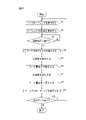
- the flow shown in FIG. 12 is started when the processor 102 of the control device 16 receives a work start command from the operator, the host controller, or the work program.
- the chuck mechanism 58 of the positioner 34 is arranged around the axis A4 from the position shown in FIG. 2 at a position rotated approximately 90 ° in the counterclockwise direction when viewed from the rear. ..
- the axis A1 of the chuck mechanism 58 is substantially parallel to the z-axis direction of the coordinate system C, and the tip surface 64b of the chuck body portion 64a faces upward. Further, the chuck claws 64c and 64d are maintained in an open state. Further, the positioner 34 is arranged at a predetermined initial position P1_0 . This initial position P1_0 may be set at the left end of the movement stroke of the positioner 34.
- the chuck mechanism 70 of the positioner 36 is The axis A2 is arranged so as to be substantially parallel to the z-axis direction of the coordinate system C and the tip surface 76b of the chuck main body portion 76a faces upward. Further, the chuck claws 76c and 76d are maintained in an open state. Further, the positioner 36 is arranged at a predetermined initial position P 2_0 . This initial position P 2_0 may be set at the right end of the movement stroke of the positioner 36.
- the elevating table 80 (that is, the work table 82) is arranged at a predetermined upper position P3-1 .
- step S1 the processor 102 executes work loading. Specifically, the processor 102 operates a work-loading robot (not shown) different from the robot 12, picks up the work W1 stored in a predetermined storage location by the work-loading robot, and picks up the work pedestal 82. Set to.
- a work-loading robot not shown
- the work W1 is placed on the work table 82, and the work table 82 supports the work W1 from below.
- the work W1 is placed on the work table 82 so as to be relatively slidable without being fixed to the work table 82 by a jig or the like.
- the uneven portion 92c is formed on the surface 92b of the work table 82, the work W1 placed on the work table 82 due to the frictional force between the work W1 and the uneven portion 92c. Misalignment is suppressed.
- the processor 102 operates the work-loading robot, picks up the work W2 conveyed by the supply conveyor by the work-loading robot, and sets it on the tip surface 64b of the chuck mechanism 58 of the positioner 34. Then, the processor 102 operates the first chuck claw driving unit to close the chuck claws 64c and 64d, and causes the chuck claws 64c and 64d to grip the work W2. In this way, the positioner 34 (specifically, the chuck 64) grips the work W2.
- the processor 102 operates the work-loading robot, picks up the work W3 conveyed by the supply conveyor by the work-loading robot, and sets it on the tip surface 76b of the chuck mechanism 70 of the positioner 36. Then, the processor 102 operates the second chuck claw driving unit to close the chuck claws 76c and 76d, and causes the chuck claws 76c and 76d to grip the work W3. In this way, the positioner 36 (specifically, the chuck 76) grips the work W3.
- the processor 102 operates the drive unit 46 (FIG. 3) to rotate the chuck mechanism 58 around the axis A4 by approximately 90 ° in the clockwise direction when viewed from the rear, and also operates the drive unit 48. Then, the chuck mechanism 70 is rotated around the axis A5 by approximately 90 ° in the counterclockwise direction when viewed from the rear.
- the chuck mechanism 58 and the work W1 and the chuck mechanism 70 and the work W3 are arranged at the positions shown in FIG.
- the axis A3 of the work W1 placed on the work table 82 arranged at the upper position P3_1 , the axis A1 of the chuck mechanism 58, and the axis A2 of the chuck mechanism 70 are parallel to the x-axis of the coordinate system C. Align on a straight line.
- step S2 the processor 102 starts moving the positioners 34 and 36. Specifically, the processor 102 generates a position command CP 1-11 for positioning the positioner 34 at the target position P 1-1 , and controls the drive unit 40 according to the position command CP 1-1-1 (position control).
- the working device 14 further has a position sensor 110 (FIG. 1) for detecting the position of the positioner 34 (specifically, the position of the coordinate system C in the x-axis direction).
- the position sensor 110 is, for example, a rotation detector (encoder, a Hall element, etc.) that detects the rotation (for example, a rotation position or a rotation angle) of the rotation shaft of the drive unit 40, or a positioner in the x-axis direction of the coordinate system C. It has a linear scale that detects the position of 34.
- the processor 102 generates a position command CP 1-11 based on the position feedback FB P1 from the position sensor 110 to control the drive unit 40, and moves the positioner 34 from the initial position P1_1 to the target position P1-11 and approaches the positioner 36. Move in the direction (ie, to the right).
- the target position P1-1 is a position where the work W2 gripped by the positioner 34 is separated to the left from the left end of the work W1 placed on the work table 82 (strictly speaking, the contact member B protruding from the left opening end). , Predetermined by the operator.
- the processor 102 generates a position command CP 2_1 for positioning the positioner 36 at the target position P 2_1 , and controls the drive unit 42 according to the position command CP 2_1 (position control).
- the processor 102 functions as a position control unit 116 (FIG. 1) that controls the drive unit 42 so as to position the positioner 36 at the target position P2-1 .
- the working device 14 further has a position sensor 112 (FIG. 1) for detecting the position of the positioner 36 (specifically, the position of the coordinate system C in the x-axis direction).
- the position sensor 112 is, for example, a rotation detector (encoder, a Hall element, etc.) that detects the rotation (for example, a rotation position or a rotation angle) of the rotation shaft of the drive unit 42, or a positioner in the x-axis direction of the coordinate system C. It has a linear scale that detects the position of 36.
- the processor 102 generates a position command CP 2_1 based on the position feedback FB P2 from the position sensor 112 to control the drive unit 40, and causes the positioner 36 to approach the positioner 34 from the initial position P 2_1 to the target position P 2_1 . Move in the direction (ie, to the left).
- This target position P 2_1 is a position where the work W3 gripped by the positioner 36 is separated to the right from the right end of the work W1 placed on the work table 82 (strictly speaking, the contact member B protruding from the right opening end). Is predetermined by the operator.
- step S3 the processor 102 determines whether the positioners 34 and 36 have reached the target positions P1-1 and P2-1 . Specifically, the processor 102 determines whether or not the positioner 34 has reached the target position P1-1 based on the position feedback FB P1 from the position sensor 110, and determines whether or not the position feedback FB P2 from the position sensor 112. Based on this, it is determined whether or not the positioner 36 has reached the target position P2-1 .
- step S4 determines YES and proceeds to step S4, while the positioner 34 does not reach the target position P1-1 . Or, if the positioner 36 has not reached the target position P2-1 , it is determined as NO, and step S3 is looped.
- step S3 the processor 102 stops the positioners 34 and 36. At this time, even if the processor 102 ends the position control of the drive unit 40 and continues the position control of the drive unit 42 based on the position feedback FB P2 , the positioner 36 is positively maintained at the target position P2_1 . good.
- the work W2 gripped by the positioner 34 is separated from the work W1 (contact member B) by a distance x 1 to the left, while the work W3 gripped by the positioner 36 is the work W1 ( It separates from the backing member B) to the right by a distance x 2 .
- the target position P 1-1 and the target position P 2_1 may be set so that the distance x 1 is substantially the same as or larger than the distance x 2 (x 1 ⁇ x 2 ). Further, the target position P 2_1 may be set so that the distance x 2 is smaller than the maximum sliding stroke x S in which the slide mechanism 84 slides the work base 82 (x 2 ⁇ x s ).
- step S4 the processor 102 executes the process of sandwiching the work W1.
- step S4 will be described with reference to FIG.
- step S11 the processor 102 operates the drive unit 40 to move the positioner 34 further to the right from the target position P1-1 .
- the speed V 1 for moving the positioner 34 in step S11 may be set lower than the speed V 2 for moving the positioner 34 in step S2 described above (that is, V 1 ⁇ V 2 ).
- the working device 14 further includes a force sensor 114 that detects a force F that the positioner 34 moved to the right by the drive unit 40 pushes the work W1.
- the force sensor 114 has a torque sensor that detects the load torque F 1 applied to the rotating shaft of the drive unit 40, and transmits the detection data DD of the load torque F 1 to the control device 16.
- the force sensor 114 has a current sensor that acquires the feedback current F 2 of the drive unit 40, and transmits the detection data DD of the feedback current F 2 to the control device 16. This feedback current F 2 corresponds to the load torque F 1 .
- the force sensor 114 is provided on the chuck mechanism 58 (for example, chuck 64) or the work W2 , and has a strain gauge or the like for detecting the force F3 applied to the chuck mechanism 58 or the work W2 from the work W1. Then , the detection data DD of the force F3 is transmitted to the control device 16.
- step S12 the processor 102 starts acquiring the force F. Specifically, the processor 102 continuously (for example, periodically) outputs the detection data DD (load torque F 1 , feedback current F 2 , or force F 3 ) detected by the force sensor 114 through the I / O interface 106. To get to.
- the detection data DD load torque F 1 , feedback current F 2 , or force F 3
- the processor 102 acquires the detection data DD as the data of the force F.
- the processor 102 is applied to the right from the positioner 34 (work W2) to the work W1 based on the detection data DD (eg, load torque F1 or feedback current F2) acquired from the force sensor 114 .
- the force F of may be obtained by calculation.
- the processor 102 functions as a force acquisition unit 118 (FIG. 1) for acquiring the force F.
- step S13 the processor 102 determines whether or not the most recently acquired force F exceeds a predetermined threshold value F th1 (F> F th1 ).
- This threshold value F th1 is predetermined with respect to the force F and is stored in the memory 104.
- this threshold value F th 1 is the rated value (or feedback current F 2) of the load torque F 1 (or feedback current F 2 ).
- the maximum value can be set as a value between 15% and 20%.
- step S4 the processor 102 ends step S4 and proceeds to step S5 in FIG.
- step S14 the processor 102 determines NO and proceeds to step S14.
- step S14 the processor 102 determines whether or not the positioner 34 has reached the target position P1-2 based on the position feedback FB P1 .
- the target position P1-2 is separated from the target position P1-1 in step S2 to the right by a predetermined distance x3 , and the work W2 gripped by the positioner 34 is separated from the work W3 gripped by the positioner 36. Is predetermined by the operator as a position where the force F can be held.
- the processor 102 determines YES and stops the positioner 34. Then, the processor 102 ends step S4 and proceeds to step S5 in FIG. On the other hand, if the positioner 34 has not reached the target position P1-2 , the processor 102 determines NO and returns to step S13. The processor 102 may determine in step S14 whether or not the distance moved by the positioner 34 from the start time of step S11 has reached a predetermined distance x 3 .
- step S4 the processor 102 controls the drive unit 40 (force control) based on the force F acquired from the force sensor 114, and moves the positioner 34 to the right. Then, the work W2 gripped by the positioner 34 pushes the work W1 placed on the work table 82 with the force F. In response to this force F, the work pedestal 82 slides to the right by the slide mechanism 84 together with the work W1 (FIGS. 9 and 10).
- step S4 the work W1 is sandwiched between the work W2 held by the positioner 34 and the work W3 held by the positioner 36.
- the processor 102 functions as a force control unit 120 (FIG. 1) that controls an operation in which the drive unit 40 causes the positioners 34 and 36 to sandwich the work W1 based on the force F.
- step S5 the processor 102 executes temporary welding. Specifically, the processor 102 operates the robot 12 to spot-weld a plurality of points at the contact points between the work W1 (contact member B) and the work W2 by the end effector 28, and the work W1 (contact). A plurality of points at the contact points between the member B) and the work W3 are spot welded.
- step S6 the processor 102 lowers the work pedestal 82. Specifically, the processor 102 operates the drive unit 44 to move the elevating table 80 (that is, the work table 82) downward from the upper position P3_1 to the predetermined lower position P3_2 . Then, the work pedestal 82 is separated downward from the work W1 sandwiched between the positioners 34 and 36, and at the same time, slides to the left by the action of the urging portion 100 of the slide mechanism 84, as shown in FIGS. 7 and 8. It returns to the indicated initial position.
- the elevating table 80 that is, the work table 82
- step S7 the processor 102 executes the main welding. Specifically, the processor 102 operates and rotates the second rotary table drive unit in synchronization with operating the rotary table drive unit to rotate the rotary table 62 (that is, the work W2). The table 74 (that is, the work W3) is rotated. As a result, the works W1, W2 and W3 are rotated around the axes A1 and A2.
- the processor 102 operates the robot 12 and causes the end effector 28 to cover the contact point between the work W1 (contact member B) and the work W2 over the entire circumference. At the same time, the contact points between the work W1 (contact member B) and the work W3 are welded over the entire circumference. In this way, the works W1, W2 and W3 are welded to each other.
- step S8 the processor 102 raises the work pedestal 82. Specifically, the processor 102 operates the drive unit 44 to move the elevating table 80 (work stand 82) upward from the lower position P 3_1 to the upper position P 3_1 . Then, the work pedestal 82 comes into contact with the work W1 sandwiched between the positioners 34 and 36, and supports the work W1 again from below.
- step S9 the processor 102 performs work unloading. Specifically, the processor 102 opens the chuck claws 64c and 64d of the chuck mechanism 58 and opens the chuck claws 76c and 76d of the chuck mechanism 70. Next, the processor 102 operates the drive unit 40 to move the positioner 34 to the left to return to the initial position P1_0 , and also operates the drive unit 42 to move the positioner 36 to the right to the initial position P. Return to 2_0 .
- the processor 102 operates the drive unit 46 (FIG. 3) to rotate the chuck mechanism 58 around the axis A4 by approximately 90 ° in the counterclockwise direction when viewed from the rear, and the drive unit 48 (FIG. 3). ) Is operated to rotate the chuck mechanism 70 around the axis A5 by approximately 90 ° in the clockwise direction when viewed from the rear.
- the processor 102 operates the work-loading robot, picks up the assembly of the works W1, W2, and W3 by the work-loading robot, and conveys them to a predetermined storage location.
- step S10 the processor 102 determines whether or not there are workpieces W1, W2, and W3 to be welded next. For example, the processor 102 can determine whether or not there are workpieces W1, W2, and W3 to be welded next by analyzing the work program. If the determination is YES, the processor 102 returns to step S1, while if the determination is NO, the processor 102 ends the flow shown in FIG.
- the slide mechanism 84 slidably supports the work stand 82 in the direction in which the positioner 34 approaches the positioner 36 (that is, to the right).
- the slide mechanism 84 when the positioner 34 moves to the right and the work W1 placed on the work table 82 is sandwiched by the positioners 34 and 36 (specifically, the work W2 and W2), the work from the positioner 34
- the force F applied to W1 can be absorbed by the sliding operation.
- the error can be canceled to some extent by the slide operation.
- the work W1, W2 and W3 can be sandwiched by the positioners 34 and 36 so that the work W1 and the work W2 and W3 are appropriately brought into contact with each other.
- the slide mechanism 84 has an urging portion 100 that urges the work pedestal 82 to the left when the work pedestal 82 slides to the right. According to this configuration, the work table 82 can be automatically returned to the initial position in step S6 with a relatively simple structure.
- the processor 102 functions as a force control unit 120, and the positioners 34 and 36 are controlled by force-controlling the drive unit 40 based on the acquired force F so that the force F does not become excessive.
- the operation of sandwiching the work W1 is being executed (step S4). According to this configuration, the force F applied from the positioner 34 to the work W1 in step S4 can be more effectively managed and optimized by the slide operation and the force control by the slide mechanism 84. As a result, the welding quality can be improved more effectively.
- the processor 102 functions as a position control unit 116 and controls the position of the drive unit 42 so as to position the positioner 36 to the target position P 2_1 before step S4 (step S2). ). Then, when the positioner 36 is positioned at the target position P2-11 , the processor 102 functions as a force control unit 120, controls the drive unit 40 by force, and moves the positioner 34 to the right (step S4). ).
- the works W1, W2, and W3 sandwiched between the positioners 34 and 36 in step S4 can be positioned at known positions with respect to the target position P2_1 of the positioner 36. Therefore, in steps S5 and S7, the end effector 28 of the robot 12 can be accurately positioned at the contact point between the work W1 (contact member B) and the works W2 and W3, so that the welding work in steps S5 and S7 is highly efficient. Can be executed accurately.
- the target position P2_1 of the positioner 36 in step S2 is defined as a position where the work W3 gripped by the positioner 36 separates from the work W1. Then, in response to pushing the work W1 by the work W2 in step S4, the slide mechanism 84 slides the work stand 82 to the right and sandwiches the work W1 between the works W2 and 3.
- the work base 82 can be reliably slid to the right in step S4, and the work W3 gripped by the positioner 36 in step S2 hits the work W1 and an excessive force is applied. Can be prevented. Therefore, it is possible to prevent the work W1 from being tilted due to the work W3.
- the processor 102 may continue the force control of the drive unit 40 in step S4 until the end of step S7.
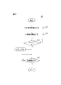
- FIG. FIG. 14 shows another example of step S4.
- the processor 102 after determining YES in step S13 or S14, the processor 102 starts the above-mentioned step S5 and executes steps S15 to S17 in parallel with steps S5 to S7.
- step S15 the processor 102 determines whether or not the most recently acquired force F is within the predetermined allowable range [F th2 , F th3 ].
- the lower limit value F th2 of this allowable range [F th2 , F th3 ] is predetermined with respect to the force F as a value smaller than the above-mentioned threshold value F th1 .
- the upper limit value F th3 is predetermined with respect to the force F as a value larger than the lower limit value F th2 .
- the upper limit value F th3 may be set to the same value as the above-mentioned threshold value F th1 or may be set to a value slightly smaller (or larger) than the threshold value F th1 .
- the processor 102 determines YES if F th2 ⁇ F ⁇ F th3 and proceeds to step S17, while the processor 102 determines NO if F ⁇ F th2 or F> F th3 and proceeds to step S16. ..
- step S16 the processor 102 moves the positioner 34. For example, if NO is determined in the latest step S15 because F ⁇ F th2 , the processor 102 moves the positioner 34 to the right by a predetermined distance x 4 . On the other hand, if NO is determined by the fact that F> F th3 in the latest step S15, the processor 102 moves the positioner 34 to the left by a predetermined distance x 5 .
- the positions 34 and 36 may be attracted to each other due to bending of the work W1, W2, or W3.
- the force F may decrease, and the holding force of the works W1, W2, and W3 by the positioners 34 and 36 may decrease inappropriately.
- the positions 34 and 36 may be pushed in a direction away from each other due to expansion of the work W1, W2 or W3 or the like. In this case, the force F may increase and the drive units 40 and 42 may be overloaded.
- the processor 102 moves the positioner 34 in the step S16 in a direction in which the force F can be contained within the allowable range [F th2 , F th3 ].
- the position of the positioner 34 can be appropriately adjusted according to the deformation. Therefore, it is possible to prevent the holding forces of the works W1, W2 and W3 by the positions 34 and 36 from being inappropriately lowered or the drive units 40 and 42 from being overloaded during steps S5 to S7.
- step S17 the processor 102 determines whether or not the main welding process of step S7 is completed. If the processor 102 determines YES, the processor 102 ends step S4 (that is, force control) and stops the positioner 34, while if it determines NO, the processor 102 returns to step S15. In this way, the processor 102 repeatedly executes steps S15 to S17 until it determines NO in step S17, so that the force F is within a predetermined allowable range [F th2 , F th3 ] during steps S5 to S7. , The drive unit 40 is force-controlled.
- the distances x 4 and x 5 used in step S16 may have the same value or different values. Further, the distance x 4 (or x 5 ) may be set so as to change according to the difference ⁇ F between the recently acquired force F and the lower limit value F th2 (or the upper limit value F th3 ). For example, the larger the difference ⁇ F, the larger the distance x 4 (or x 5 ) may be set.
- the processor 102 may generate a position command CP 1-2 for positioning the positioner 34 at the target position P 1-2 , and may control the position of the drive unit 40 according to the position command CP 1-2 . In this case, the processor 102 will execute the force control and the position control in parallel in step S4.
- FIG. 15 shows still another example of step S4.
- the same process as the flow of FIG. 14 is assigned the same step number, and duplicate description will be omitted.
- the processor 102 executes step S12 and starts acquiring the force F.
- step S21 the processor 102 starts force control. Specifically, the processor 102 generates a force command CF.
- This force command CF is a command for defining a target value of the force F (for example, 5 [kN]).
- the processor 102 generates a force command CF, calculates the difference between the force F and the force command CF most recently acquired from the force sensor 114, and based on the difference, commands C40 (command C40) to the drive unit 40. Generate speed command, torque command).
- the drive unit 40 controls the drive unit 40 according to the command C40 to move the positioner 34.
- the positioner 34 is located at the initial position P1_0 , and the force F acquired from the force sensor 114 is substantially zero. Therefore, after the start of step S21, the drive unit 40 moves the positioner 34 to the right according to the force command CF (command C40). In this way, the processor 102 force-controls the drive unit 40 so as to match the force F with the force command CF according to the force F acquired from the force sensor 114.
- step S13 the processor 102 executes step S13, starts step S5 if it is determined to be YES, and proceeds to step S17, while looping step S13 if it is determined to be NO.
- the threshold value F th1 used in step S13 at this time can be set to a value smaller than the force command CF (for example, 5 kN). In this way, the processor 102 force-controls the drive unit 40 so that the force F coincides with the force command CF during steps S5 to S7 in FIG. As a result, the force F applied from the positioner 34 to the work W1 during steps S5 to S7 can be effectively managed and optimized.
- the force sensor 114 may be arranged so as to detect the force F applied to the positioner 36 via the works W1, W2 and W3 by the positioner 34 moved to the right by the drive unit 40.
- the force sensor 114 is provided in the torque sensor that detects the load torque of the drive unit 42, the current sensor that acquires the feedback current F 2 of the drive unit 42, the chuck mechanism 70 (chuck 76), or the work W3. It may have a strain gauge.
- the processor 102 may execute the above-mentioned step S4 based on the force F applied to the positioner 36. Further, the processor 102 may execute step S15 in FIG. 14 instead of step S13 shown in FIG. 15, and if YES is determined, the processor 102 may start step S5 and proceed to step S17.
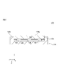
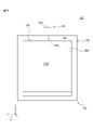
- the work support mechanism 122 has a work stand 124 and a slide mechanism 126 in addition to the support column 78 and the elevating table 80 (FIG. 5) described above.
- the work table 124 is a substantially quadrangular flat plate member, and the work W1 is placed on the upper surface 124a thereof.
- the slide mechanism 126 is fixed on the support base 86 of the elevating table 80, and slidably supports the work base 124 in the x-axis direction of the coordinate system C.
- the slide mechanism 126 has a main body portion 130, a plurality of rollers 132 (FIG. 17), and an urging portion 134.
- the main body 130 has an upper surface 130a and a sliding groove 130b recessed downward from the upper surface 130a.
- the sliding groove 130b has a substantially quadrangular outer shape, and has a length in the x-axis direction of the coordinate system C, which is longer than the work table 124.
- the work base 124 is slidably received in the sliding groove 130b in the x-axis direction of the coordinate system C.
- Each of the rollers 132 is provided inside the sliding groove 130b so as to be rotatable around an axis substantially parallel to the y-axis of the coordinate system C, and the work base 124 is installed on the roller 132. To. Due to the rotation of the roller 132, the work base 124 can slide in the sliding groove 130b between the initial position shown in FIG. 16 and the sliding position shown in FIG.
- the slide mechanism 126 allows the work pedestal 124 to slide to the right from the initial position, while restricting the work pedestal 124 to slide to the left from the initial position.
- the urging unit 134 urges the work pedestal 124 to the left when the work pedestal 124 slides to the right from the initial position to the sliding position.
- the urging portion 134 is a pneumatic or hydraulic cylinder, a servomotor, or the like, and is a drive shaft 134a provided on the main body portion 130 so as to be able to move forward and backward in the x-axis direction of the coordinate system C. It has a power unit 134b for advancing and retreating the drive shaft 134a.
- the tip of the drive shaft 134a is mechanically connected to the work base 124.
- the power unit 134b advances the drive shaft 134a in response to a command from the control device 16 to urge the work pedestal 124 arranged at the sliding position to the left toward the initial position.
- the urging unit 134 is a device that can be automatically controlled by the control device 16.
- the processor 102 moves the positioner 34 to the left in order to sandwich the work W1 between the works W2 and W3 in step S4. Press work W1 on work W2.
- the work pedestal 124 slides to the right from the initial position (FIG. 16) to the sliding position (FIG. 18) by the action of the slide mechanism 126, and as a result, the work W1 moves to the works W2 and W3. It is sandwiched between.
- step S6 (or when step S6 is started and the work pedestal 124 is separated from the work W1), the processor 102 operates the urging portion 134 to initially move the work pedestal 124 from the sliding position. Slide to the left to the position. As a result, the work table 124 returns to the initial position.
- the work pedestal 124 since the work pedestal 124 can be urged to the initial position after the work pedestal 124 is separated from the work W1, the work pedestal 124 relatively slides on the work W1 when the step S6 is executed. This makes it possible to prevent the work W1 from being scratched or the like.
- the above-mentioned slide mechanism 84 may further include a lock mechanism that locks the work table 82 when the work table 82 slides to the right and reaches a predetermined sliding position.
- the lock mechanism engages with the work pedestal 82 in the sliding position to restrict the sliding of the work pedestal 82 to the left, and the locking mechanism is detached from the work pedestal 82.
- It may have an engaging pin that can move forward and backward between the position and a power unit (cylinder, servomotor, etc.) that automatically moves the engaging pin forward and backward in response to a command from the control device 16.
- step S4 when the work base 82 slides from the initial position to the sliding position in step S4, the processor 102 operates the power unit of the lock mechanism to engage the engaging pin with the work base 82.
- the work stand 82 is locked to the sliding position.
- the processor 102 operates the power unit of the lock mechanism to disengage the engaging pin from the work pedestal 82 after step S6 (or when the work pedestal 82 separates from the work W1 after starting step S6). By releasing it, the lock mechanism is unlocked.
- the work base 82 slides to the left by the action of the urging portion 100 and automatically returns to the initial position. According to this configuration, it is possible to prevent the work W1 from being scratched or the like due to the work table 82 relatively sliding on the work W1 during the execution of step S6.
- the drive unit 42 may be omitted and the positioner 36 may be fixed at a predetermined position (for example, the above-mentioned target position P2_1 ).
- the processor 102 may execute the force control shown in FIG. 13, FIG. 14 or FIG. 15 with respect to the drive unit 42 based on the acquired force F. good.
- the force sensor 114 may be arranged so as to detect the force F applied to the positioner 36 as described above.
- step S4 described above the processor 102 generates the position command CP 1-2 for positioning the positioner 34 at the target position P 1-2 without performing force control, and causes the drive unit 40 according to the position command CP 1-2 .
- the position may be controlled.
- the industrial machine 10 performs the welding work has been described.
- the industrial machine 10 may be configured to perform any kind of work such as cutting with a tool, laser processing with a laser beam, or painting.
- the end effector 28 has a tool, a laser processing head, and a paint applicator.
- the rotary table 62 can be omitted.
- the slide mechanism 84 may be configured to allow the work table 82 to slide to the left from the initial position. That is, in this case, the slide mechanism 84 slidably supports the work stand 82 from the initial position to the left and right. Further, the urging portion 100 or 134 may be omitted from the slide mechanism 84 or 126 described above. In this case, the operator may manually slide the work base 82 or 124 to the left or right.
Landscapes
- Engineering & Computer Science (AREA)
- Mechanical Engineering (AREA)
- Physics & Mathematics (AREA)
- Optics & Photonics (AREA)
- Jigs For Machine Tools (AREA)
- Manipulator (AREA)
- Machine Tool Units (AREA)
- Automatic Assembly (AREA)
Abstract
Description
その軸線A2が座標系Cのz軸方向と略平行となり、チャック本体部76aの先端面76bが上方を向くように、配置されている。また、チャック爪76c及び76dは、開いた状態に維持される。また、ポジショナ36は、所定の初期位置P2_0に配置されている。この初期位置P2_0は、ポジショナ36の移動ストロークの右端に定められてもよい。そして、昇降台80(すなわち、ワーク置台82)は、所定の上側位置P3_1に配置されている。
12 ロボット
14 作業装置
16 制御装置
28 エンドエフェクタ
34,36 ポジショナ
40,42,44,46,48 駆動部
62,74 回転テーブル
84,126 スライド機構
100,134 付勢部
110,112 位置センサ
114 力センサ
116 位置制御部
118 力取得部
120 力制御部
Claims (8)
- 第1のワークが置かれるワーク置台と、
前記ワーク置台に置かれた前記第1のワークを挟持する一対のポジショナであって、該一対のポジショナの一方は他方に対して接近及び離反するように移動可能に設けられている、一対のポジショナと、
前記ワーク置台を、前記一方が前記他方に接近する方向へ摺動可能に支持するスライド機構と、を備える、産業機械。 - 前記スライド機構は、前記ワーク置台が所定の初期位置から前記接近する方向へ摺動するのを許容する一方、該ワーク置台が該初期位置から、前記接近する方向とは反対の方向へ摺動するのを規制する、請求項1に記載の産業機械。
- 前記スライド機構は、前記ワーク置台が前記接近する方向へ摺動したときに、該ワーク置台を、前記接近する方向とは反対の方向へ付勢する付勢部を有する、請求項1又は2に記載の産業機械。
- 前記一方を移動させる第1の駆動部と、
前記第1の駆動部によって前記接近する方向へ移動される前記一方が前記第1のワークを押す力を取得する力取得部と、
前記力取得部が取得した前記力に基づいて、前記第1の駆動部が前記一方を前記接近する方向へ移動して前記一対のポジショナに前記第1のワークを挟持させる動作を制御する力制御部と、をさらに備える、請求項1~3のいずれか1項に記載の産業機械。 - 前記他方は、前記一方に対して接近及び離反するように移動可能に設けられ、
前記産業機械は、
前記他方を移動させる第2の駆動部と、
前記力制御部が前記一対のポジショナに前記第1のワークを挟持させる前に、前記他方を予め定めた目標位置へ位置決めするように前記第2の駆動部を制御する位置制御部と、をさらに備え、
前記力制御部は、前記位置制御部が前記他方を前記目標位置へ位置決めしたときに、前記第1の駆動部を制御して前記一方を前記接近する方向へ移動させる、請求項4に記載の産業機械。 - 前記一方は、第2のワークを把持し、前記他方は、第3のワークを把持し、
前記目標位置は、前記他方が把持する前記第3のワークが前記第1のワークから離反する位置として定められ、
前記力制御部が前記一方を前記接近する方向へ移動させて前記第2のワークで前記第1のワークを押すのに応じて、前記スライド機構は、前記ワーク置台を前記接近する方向へ摺動させ、
前記一対のポジショナは、前記第1のワークを、前記一方が把持する前記第2のワークと、前記目標位置に位置決めされた前記他方が把持する前記第3のワークとの間で挟持する、請求項5に記載の産業機械。 - 前記一対のポジショナが前記第1のワークを挟持しているときに、前記第1のワークと前記第2のワークとを互いに溶接するとともに、前記第1のワークと前記第3のワークとを互いに溶接する溶接トーチをさらに備える、請求項6に記載の産業機械。
- 前記一対のポジショナの各々は、挟持した前記第1のワークを、前記接近する方向と平行な軸線の周りに回転させる回転テーブルを有する、請求項1~7のいずれか1項に記載の産業機械。
Priority Applications (4)
| Application Number | Priority Date | Filing Date | Title |
|---|---|---|---|
| US18/034,931 US20240009781A1 (en) | 2020-11-09 | 2021-11-02 | Industrial machine provided with pair of positioners for holding workpiece |
| DE112021004789.2T DE112021004789T5 (de) | 2020-11-09 | 2021-11-02 | Industriemaschine mit paar positionierer zum halten eines werkstücks |
| CN202180075255.2A CN116419817A (zh) | 2020-11-09 | 2021-11-02 | 具备用于夹持工件的一对定位器的工业机械 |
| JP2022560792A JP7553594B2 (ja) | 2020-11-09 | 2021-11-02 | ワークを挟持する一対のポジショナを備える産業機械 |
Applications Claiming Priority (2)
| Application Number | Priority Date | Filing Date | Title |
|---|---|---|---|
| JP2020186645 | 2020-11-09 | ||
| JP2020-186645 | 2020-11-09 |
Publications (1)
| Publication Number | Publication Date |
|---|---|
| WO2022097650A1 true WO2022097650A1 (ja) | 2022-05-12 |
Family
ID=81457293
Family Applications (1)
| Application Number | Title | Priority Date | Filing Date |
|---|---|---|---|
| PCT/JP2021/040422 Ceased WO2022097650A1 (ja) | 2020-11-09 | 2021-11-02 | ワークを挟持する一対のポジショナを備える産業機械 |
Country Status (6)
| Country | Link |
|---|---|
| US (1) | US20240009781A1 (ja) |
| JP (1) | JP7553594B2 (ja) |
| CN (1) | CN116419817A (ja) |
| DE (1) | DE112021004789T5 (ja) |
| TW (1) | TWI896803B (ja) |
| WO (1) | WO2022097650A1 (ja) |
Families Citing this family (2)
| Publication number | Priority date | Publication date | Assignee | Title |
|---|---|---|---|---|
| CN119404601A (zh) | 2022-06-13 | 2025-02-07 | 千住金属工业株式会社 | 喷流焊接装置 |
| CN118404273B (zh) * | 2024-05-30 | 2024-11-19 | 河南中业重工机械有限公司 | 输送机结构件焊接机器人生产线 |
Citations (2)
| Publication number | Priority date | Publication date | Assignee | Title |
|---|---|---|---|---|
| JPH1190685A (ja) * | 1997-09-22 | 1999-04-06 | Kobe Steel Ltd | 2以上の加工物の連結溶接方法および装置 |
| JP2000094248A (ja) * | 1998-09-25 | 2000-04-04 | Toyota Autom Loom Works Ltd | ワーク固定装置及びワーク固定装置のブッシュ爪段取替装置 |
Family Cites Families (13)
| Publication number | Priority date | Publication date | Assignee | Title |
|---|---|---|---|---|
| FR2201160B1 (ja) * | 1972-09-29 | 1980-02-15 | Delog Detag Flachglas Ag | |
| JP3623684B2 (ja) * | 1999-03-10 | 2005-02-23 | Jfeスチール株式会社 | コラムリング溶接装置 |
| JP2006102887A (ja) * | 2004-10-06 | 2006-04-20 | Sagami Precision Kk | ワーククランプ装置 |
| JP5563845B2 (ja) | 2010-02-16 | 2014-07-30 | 株式会社神戸製鋼所 | 仕口用溶接支持台 |
| JP2011177746A (ja) * | 2010-03-01 | 2011-09-15 | Kobe Steel Ltd | クランプ確認システム、溶接ロボットシステム、クランプ治具制御装置およびクランプ確認方法 |
| CN103625091B (zh) * | 2012-08-24 | 2016-01-06 | 鸿富锦精密工业(深圳)有限公司 | 定位机构及采用该定位机构的贴合设备 |
| US10265809B2 (en) * | 2013-05-13 | 2019-04-23 | Dana Automotive Systems Group, Llc | Method of joining workpieces using a sliding part coupling portion |
| JP5734398B2 (ja) * | 2013-11-28 | 2015-06-17 | ファナック株式会社 | 物体を受け部に固定するための物体固定装置、工作機械、ロボット、および物体を受け部に固定する方法 |
| JP6233053B2 (ja) | 2014-01-27 | 2017-11-22 | 日産自動車株式会社 | 溶接部品の製造方法 |
| CN108393692B (zh) * | 2018-03-06 | 2020-09-11 | 吉林省金沙数控机床股份有限公司 | 一种用于加工盘形工件的自动生产线 |
| CN109108543B (zh) * | 2018-10-17 | 2024-05-28 | 佛山市固高自动化技术有限公司 | 采用机器人上料和下料的储液罐自动焊接设备 |
| CN209062323U (zh) * | 2018-10-18 | 2019-07-05 | 重庆驰骋轻型汽车部件股份有限公司 | 双机器人弧焊工作站 |
| CN110773756B (zh) * | 2019-10-25 | 2021-05-14 | 重庆第二机床厂有限责任公司 | 自动车削专机系统 |
-
2021
- 2021-11-02 JP JP2022560792A patent/JP7553594B2/ja active Active
- 2021-11-02 US US18/034,931 patent/US20240009781A1/en active Pending
- 2021-11-02 WO PCT/JP2021/040422 patent/WO2022097650A1/ja not_active Ceased
- 2021-11-02 CN CN202180075255.2A patent/CN116419817A/zh active Pending
- 2021-11-02 DE DE112021004789.2T patent/DE112021004789T5/de active Pending
- 2021-11-03 TW TW110140986A patent/TWI896803B/zh active
Patent Citations (2)
| Publication number | Priority date | Publication date | Assignee | Title |
|---|---|---|---|---|
| JPH1190685A (ja) * | 1997-09-22 | 1999-04-06 | Kobe Steel Ltd | 2以上の加工物の連結溶接方法および装置 |
| JP2000094248A (ja) * | 1998-09-25 | 2000-04-04 | Toyota Autom Loom Works Ltd | ワーク固定装置及びワーク固定装置のブッシュ爪段取替装置 |
Also Published As
| Publication number | Publication date |
|---|---|
| TWI896803B (zh) | 2025-09-11 |
| CN116419817A (zh) | 2023-07-11 |
| JP7553594B2 (ja) | 2024-09-18 |
| DE112021004789T5 (de) | 2023-08-31 |
| TW202218792A (zh) | 2022-05-16 |
| US20240009781A1 (en) | 2024-01-11 |
| JPWO2022097650A1 (ja) | 2022-05-12 |
Similar Documents
| Publication | Publication Date | Title |
|---|---|---|
| Frommknecht et al. | Multi-sensor measurement system for robotic drilling | |
| US20160039093A1 (en) | Low-impedance articulated device and method for assisting a manual assembly task | |
| KR102475955B1 (ko) | 다관절 아암 로봇에 부착된 보링 공구를 사용하여 고정식으로 장착된 공작물의 표면에 보어홀을 도입하기 위한 방법 및 장치 | |
| JP5423441B2 (ja) | 作業システム、ロボット装置、機械製品の製造方法 | |
| JP6628534B2 (ja) | 自動組立方法及び自動組立システム | |
| CN103419021B (zh) | 装配装置和装配室 | |
| US9821456B2 (en) | Method for the manipulation of objects by means of at least two industrial robots, and associated industrial robot | |
| KR102368247B1 (ko) | 작업물의 제한된 영역을 처리하기 위한 장치 및 방법 | |
| US11292140B2 (en) | Gripping device for gripping workpiece | |
| US10315281B2 (en) | Reconfigurable interface assembly, adaptable assembly line work-piece processor, and method | |
| JP6250900B2 (ja) | 工作機械とロボットとの協働によってワークを加工する方法 | |
| WO2022097650A1 (ja) | ワークを挟持する一対のポジショナを備える産業機械 | |
| CN1886237A (zh) | 一种用于自动装配的具有受控灵活性和仿真力的工业机器人 | |
| CN110076358A (zh) | 机床 | |
| US20250303568A1 (en) | Method and system for determining a workpiece loading location in a cnc machine with a robotic arm | |
| WO2019043554A1 (en) | MACHINE, TERMINAL EFFECTOR AND METHOD FOR WORKING POINT BY REDUCED FIXING ROBOTIC FRICTION-MIXING POINT | |
| US20210387354A1 (en) | Automatic workpiece carrying machine | |
| JP2016172296A (ja) | ロボット装置、ロボット制御プログラム、および記録媒体 | |
| JP2019038010A (ja) | レーザー加工装置、レーザー加工装置の制御方法 | |
| JP2580015Y2 (ja) | マルチチャックハンド | |
| JP2015100884A (ja) | ロボットハンド | |
| US9015917B2 (en) | Clamping and gripping device with high mechanical advantage and energy saving attributes | |
| JP7692094B1 (ja) | ハンド装置 | |
| JP2019503878A (ja) | 工作機械 | |
| Jonsson et al. | Force feedback for assembly of aircraft structures |
Legal Events
| Date | Code | Title | Description |
|---|---|---|---|
| 121 | Ep: the epo has been informed by wipo that ep was designated in this application |
Ref document number: 21889203 Country of ref document: EP Kind code of ref document: A1 |
|
| ENP | Entry into the national phase |
Ref document number: 2022560792 Country of ref document: JP Kind code of ref document: A |
|
| WWE | Wipo information: entry into national phase |
Ref document number: 18034931 Country of ref document: US |
|
| 122 | Ep: pct application non-entry in european phase |
Ref document number: 21889203 Country of ref document: EP Kind code of ref document: A1 |