WO2022097265A1 - 遠心送風機 - Google Patents
遠心送風機 Download PDFInfo
- Publication number
- WO2022097265A1 WO2022097265A1 PCT/JP2020/041503 JP2020041503W WO2022097265A1 WO 2022097265 A1 WO2022097265 A1 WO 2022097265A1 JP 2020041503 W JP2020041503 W JP 2020041503W WO 2022097265 A1 WO2022097265 A1 WO 2022097265A1
- Authority
- WO
- WIPO (PCT)
- Prior art keywords
- protrusion
- impeller
- centrifugal blower
- protrusions
- scroll casing
- Prior art date
- Legal status (The legal status is an assumption and is not a legal conclusion. Google has not performed a legal analysis and makes no representation as to the accuracy of the status listed.)
- Ceased
Links
Images


Classifications
-
- F—MECHANICAL ENGINEERING; LIGHTING; HEATING; WEAPONS; BLASTING
- F04—POSITIVE - DISPLACEMENT MACHINES FOR LIQUIDS; PUMPS FOR LIQUIDS OR ELASTIC FLUIDS
- F04D—NON-POSITIVE-DISPLACEMENT PUMPS
- F04D29/00—Details, component parts, or accessories
- F04D29/40—Casings; Connections of working fluid
- F04D29/42—Casings; Connections of working fluid for radial or helico-centrifugal pumps
- F04D29/44—Fluid-guiding means, e.g. diffusers
Definitions
- the present disclosure relates to a centrifugal blower having a scroll casing.
- the centrifugal blower has a scroll casing that houses the impeller.
- the scroll casing has an air inlet and an air outlet, and constitutes an air flow path generated by the rotation of the impeller.
- the noise generated inside the scroll casing due to the rotation of the impeller is discharged to the outside of the scroll casing from the suction port or the air outlet.
- the flow velocity of air in the centrifugal blower becomes the highest immediately after it flows out from the impeller.
- the distance between the outer circumference of the impeller in the radial direction and the inner wall surface of the scroll casing becomes longer as the impeller advances in the rotational direction.
- the conventional centrifugal blower has a problem that the pressure fluctuation on the inner wall surface of the scroll casing tends to be large and noise is generated from the inner wall surface.
- Patent Document 1 discloses a centrifugal blower in which a step protruding toward the impeller is provided on the outer peripheral wall of the scroll casing.
- the width of the flow path in the radial direction is narrowed on the side opposite to the one in which the suction port is provided in the axial direction due to the provision of the step.
- noise is reduced by making the flow velocity of air at the outlet uniform by such a configuration.
- the present disclosure has been made in view of the above, and an object thereof is to obtain a centrifugal blower capable of reducing noise.
- the centrifugal blower accommodates an impeller, a motor for rotationally driving the impeller, and an impeller, and has an air inlet and an air outlet. It also has a scroll casing, which constitutes a flow path of an air flow generated by the rotation of an impeller.
- the inner wall surface of the scroll casing which is separated from the impeller in the radial direction of the impeller, is provided with a plate-shaped protrusion protruding from the inner wall surface toward the impeller and extending in the direction of air flow. Has been done.
- the centrifugal blower according to the present disclosure has the effect of being able to reduce noise.
- FIG. 1 Perspective view of the centrifugal blower according to the first embodiment Sectional drawing of the centrifugal blower which concerns on Embodiment 1.
- Top view of the centrifugal blower according to the first embodiment The first figure for demonstrating the relationship between the fan efficiency of the centrifugal blower which concerns on Embodiment 1 and the position of a protrusion.
- FIG. 2 for explaining the relationship between the fan efficiency of the centrifugal blower according to the first embodiment and the position of the protrusion.
- the second figure which shows the state of the streamline in the centrifugal blower which concerns on Example 2 of Embodiment 1.
- Perspective view of the centrifugal blower according to the second embodiment Side view of the centrifugal blower according to the second embodiment Sectional drawing of the centrifugal blower which concerns on Embodiment 3.
- centrifugal blower according to the embodiment will be described in detail below based on the drawings.
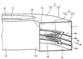
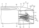
- FIG. 1 is a perspective view of the centrifugal blower 1 according to the first embodiment.
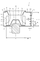
- FIG. 2 is a cross-sectional view of the centrifugal blower 1 according to the first embodiment.
- the centrifugal blower 1 has an impeller 2, a motor 3 for rotationally driving the impeller 2, and a scroll casing 4 for accommodating the impeller 2.
- the centrifugal blower 1 generates an air flow by rotating the impeller 2.
- the impeller 2 is a multi-wing impeller.
- the impeller 2 is attached to the shaft 5 of the motor 3.
- the impeller 2 rotates about the shaft 5.
- the impeller 2 has a boss portion 2a fixed to the shaft 5 and a plurality of blades 2b arranged on the peripheral edge portion of the boss portion 2a.
- the cross section shown in FIG. 2 is a cross section taken along line II-II shown in FIG. 1 and includes a rotation axis AX.
- the rotation shaft AX is the rotation center of the impeller 2.
- the axial direction is the direction of the rotation axis AX.
- the rotation direction is the direction in which the impeller 2 rotates.
- the radial direction is the direction perpendicular to the rotation axis AX.
- the scroll casing 4 has an air inlet 6 and an air outlet 7. Inside the scroll casing 4, an air flow from the suction port 6 to the air outlet 7 is generated.
- the scroll casing 4 constitutes a flow path of an air flow generated by the rotation of the impeller 2. By rotating the impeller 2, the air outside the scroll casing 4 is sucked into the inside of the scroll casing 4 through the suction port 6. By rotating the impeller 2, the air inside the scroll casing 4 is blown out of the scroll casing 4 through the outlet 7.
- FIG. 1 outside the scroll casing 4 toward the suction port 6 and an air flow Y2 from the outlet 7 to the outside of the scroll casing 4 are generated.
- a mainstream Y3 that flows from the suction port 6 through the impeller 2 and between the impeller 2 and the inner wall surface 11 of the scroll casing 4 is generated.
- the first side wall 8 and the second side wall 9 are portions of the scroll casing 4 that face each other in the axial direction, respectively.
- the outer peripheral wall 10 is a portion of the scroll casing 4 between the first side wall 8 and the second side wall 9.
- the suction port 6 is formed on the first side wall 8.
- a bell mouth 12 whose inner diameter is increased toward the outside of the scroll casing 4 is formed on the first side wall 8.
- the inner wall surface 11 is a surface of the outer peripheral wall 10 on the inner side of the scroll casing 4 and is separated from the impeller 2 in the radial direction.
- the material of the scroll casing 4 is, for example, resin.
- the scroll casing 4 has a scroll portion 13 and a diffuse portion 14.
- the scroll portion 13 is a portion constituting a spiral flow path whose width increases in the radial direction toward the downstream side of the air flow.
- the diffuser portion 14 is a portion downstream of the scroll portion 13 and constitutes a flow path between the scroll portion 13 and the air outlet 7.
- the portion of the inner wall surface 11 included in the scroll portion 13 is referred to as the inner wall surface 11a.
- the portion of the inner wall surface 11 included in the diffuse portion 14 is referred to as the inner wall surface 11b.
- the inner wall surface 11a is curved so that the distance between the outer edge 2c of the impeller 2 and the inner wall surface 11a becomes longer toward the rotation direction.
- the inner wall surface 11a is a spiral curve that moves away from the rotation axis AX as it goes in the rotation direction.
- the helix is, for example, an Archimedes logarithmic spiral. The details of the Archimedes logarithmic spiral will be described later.
- the position of the downstream end of the inner wall surface 11a is also the position of the upstream end of the inner wall surface 11b.
- the inner wall surface 11b is a flat surface.
- the diffuser portion 14 efficiently converts the dynamic pressure of the mainstream Y3 blown out from the impeller 2 into static pressure, and guides the mainstream Y3 to the outlet 7.
- the scroll casing 4 is formed with a tongue portion 15 having a shape protruding toward the inside of the scroll casing 4.
- the tongue portion 15 guides an air flow swirling inside the scroll casing 4 to the outlet 7.
- the inner wall surface 11 is provided with a plate-shaped protrusion 16 that protrudes from the inner wall surface 11 toward the impeller 2 and extends in the direction of the air flow.
- the centrifugal blower 1 according to the first embodiment is provided with three protrusions 16a, 16b, 16c having different positions in the axial direction.
- the protrusion 16 is referred to as each of the three protrusions 16a, 16b, 16c without distinction.
- Each protrusion 16 is formed so as to straddle the scroll portion 13 and the diffuse portion 14 in the scroll casing 4. That is, each protrusion 16 is formed so as to straddle the inner wall surface 11a and the inner wall surface 11b.
- the distance between the inner side surface of the scroll casing 4 of the second side wall 9 and the inner side surface of the scroll casing 4 of the first side wall 8 is defined as “A”.
- A is the length of the outlet 7 in the axial direction, and is also the height of the end 7b of the outlet 7 from the end 7a of the outlet 7 in the axial direction.
- the end 7a is the end of the outlet 7 on the side of the second side wall 9.
- the end 7b is the end of the outlet 7 on the side of the first side wall 8.
- the height of the protrusion 16 from the end 7a of the outlet 7 in the axial direction is defined as "B”.
- the height of the protrusion 16a is referred to as “Ba”
- the height of the protrusion 16b is referred to as “Bb”
- the height of the protrusion 16c is referred to as “Bc”. do.
- the protrusion length which is the distance between the edge in contact with the inner wall surface 11 and the edge on the side of the impeller 2 is defined as “C”.
- the protrusion length of the protrusion 16a is “Ca”
- the protrusion length of the protrusion 16b is “Cb”
- the protrusion length of the protrusion 16c is defined as “Cb”.
- the thickness of the protrusion 16 in the axial direction is defined as "E”.
- the thickness of the protrusion 16a is referred to as "Ea”
- the thickness of the protrusion 16b is referred to as "Eb”
- the thickness of the protrusion 16c is referred to as "Ec”. do.
- the outer diameter of the impeller 2 is set to “D”.
- the distance between the outer edge 2c of the impeller 2 and the inner wall surface 11 is defined as "WR”.
- the plate thickness of the scroll casing 4 be "F”.
- each protrusion 16 is continuously provided along the inner wall surface 11a and the inner wall surface 11b.
- Each protrusion 16 is erected in a direction perpendicular to the rotation axis AX.
- the protrusion 16a is provided at a position of a constant height "Ba" on the inner wall surface 11a and the inner wall surface 11b.
- the protrusion 16b is provided at a position of a constant height "Bb” on the inner wall surface 11a and the inner wall surface 11b.
- the protrusion 16c is provided at a position of a constant height "Bc" on the inner wall surface 11a and the inner wall surface 11b.
- the protrusion 16a is formed with a constant protrusion length "Ca”.
- the protrusion 16b is formed with a constant protrusion length "Cb”.
- the protrusion 16c is formed with a constant protrusion length "Cc”.
- the thicknesses "Ea”, “Eb” and “Ec” are equal to each other. Further, considering that the scroll casing 4 is formed by using a mold, it is desirable that the thickness “E” is about the same as the plate thickness "F" of the scroll casing 4. In the first embodiment, the thickness "E” is the same as the plate thickness "F”. As a result, each protrusion 16 can be integrally molded with the scroll casing 4. Further, in the first embodiment, the protrusion lengths “Ca”, “Cb” and “Cc” are equal to each other.
- the edge of the protrusion 16 on the impeller 2 side has a rounded shape.
- the centrifugal blower 1 has a shape in which the edge of the protrusion 16 on the side of the impeller 2 is sharper than that of the air in the vicinity of the edge of the protrusion 16 on the side of the impeller 2. The turbulence of the flow can be reduced.
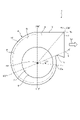
- FIG. 3 is a plan view of the centrifugal blower 1 according to the first embodiment.
- “ ⁇ ” is an angle around the rotation axis AX, and is an angle with the rotation direction of the impeller 2 as a positive direction.
- “WR ⁇ ” represents “WR” at an angle “ ⁇ ”.
- the position of the boundary between the scroll portion 13 and the diffuse portion 14 differs depending on the position of the impeller 2 or the shape of the scroll casing 4.
- the position of the air outlet 7 differs depending on the position of the impeller 2, the position of the apex of the tongue portion 15, the shape of the diffuse portion 14, and the like.
- R 0 is the radius of the helix at the reference position of the helix.
- R is the radius of the spiral at a position advanced by an angle “ ⁇ ” from the reference position in the rotation direction.
- I is the magnification of the spiral.
- the shape of the scroll casing 4 is not limited to the shape shown in FIG. 3, and can be appropriately changed.
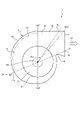
- FIG. 4 is a first diagram for explaining the relationship between the fan efficiency of the centrifugal blower 1 according to the first embodiment and the position of the protrusion 16.
- FIG. 4 shows a plan view of the centrifugal blower 1 and an example of a protrusion 16 arranged inside the scroll casing 4. In FIG. 4, the protrusion 16 is indicated by a broken line.
- the position of the end 17a on the upstream side of the air flow in the protrusion 16 can be said to be the starting point of the protrusion 16 in the rotation direction.
- the position of the end 17b on the downstream side of the air flow in the protrusion 16 can be said to be the end point of the protrusion 16 in the rotation direction.
- the position of the end 17a is referred to as a start point
- the position of the end 17b is referred to as an end point.
- ⁇ 1 is an angle formed by the virtual line N and the line connecting the start point and the rotation axis AX in the cross section of the scroll casing 4 perpendicular to the rotation axis AX.
- ⁇ 2 is an angle formed by the virtual line N and the line connecting the end point and the rotation axis AX in the cross section of the scroll casing 4 perpendicular to the rotation axis AX.
- Each of " ⁇ 1” and “ ⁇ 2" has an angle with the rotation direction of the impeller 2 as a positive direction.
- FIG. 5 is a diagram showing an example of the relationship between the fan efficiency of the centrifugal blower 1 according to the first embodiment and the starting point of the protrusion 16.
- FIG. 5 shows a solid line graph showing the relationship between the fan efficiency and “ ⁇ 1”.
- the vertical axis represents fan efficiency and the horizontal axis represents “ ⁇ 1”. From the graph shown in FIG. 5, it can be seen that the mode of change in fan efficiency when " ⁇ 1" is changed in the range of 0 ° to 330 °.
- the protrusions 16 are provided on the entire inner wall surface 11a and the inner wall surface 11b.
- the specifications of the protrusions 16 such as the number and height positions of the protrusions 16, the protrusion length of the protrusions 16, and the thickness of the protrusions 16 are as described with reference to FIGS. 1 to 3. ..
- Comparative Example 1 is a case where the scroll casing 4 is not provided with the protrusion 16. It is assumed that the scroll casing 4 in Comparative Example 1 is formed in the same manner as in the case of the first embodiment, except that the protrusion 16 is not provided.
- R2 shown by the broken line in FIG. 5 represents the fan efficiency in the case of Comparative Example 2.
- a step similar to the step disclosed in Patent Document 1 is provided in the scroll casing 4.
- the step is provided on the entire inner wall surface 11a and the inner wall surface 11b.
- the step is formed by projecting a portion of the scroll casing 4 in a height range from the end 7a of the outlet 7 to 0.50 ⁇ A toward the impeller 2.
- the portion of the scroll casing 4 having a height range from the end 7a of the outlet 7 to the position of 0.50 ⁇ A is closer to the impeller 2 by 0.095 ⁇ WR 290 ° as compared with the case of Comparative Example 1.
- the scroll casing 4 in Comparative Example 2 is formed in the same manner as in the case of the first embodiment, except that a step is provided instead of the protrusion 16.
- FIG. 5 shows an example of fan efficiency when the air volume is the same and the rotation speed is the same for the first embodiment and the comparative examples 1 and 2.
- the number of rotations is the number of times the impeller 2 rotates per unit time.
- the fan efficiency in the case of Comparative Example 1 is 43.4%.
- the fan efficiency in the case of Comparative Example 2 is 42.5%.
- the fan efficiency of the centrifugal blower 1 is higher than that of Comparative Examples 1 and 2.
- the protrusion 16 is provided at the portion where the air flows along the inner wall surface 11a, so that the rectifying effect is promoted and the fluctuation of the air flow is reduced.
- the centrifugal blower 1 can improve the fan efficiency.
- the distance between the outer edge 2c of the impeller 2 and the inner wall surface 11a is shorter than in the portion where ⁇ ⁇ 120 °.
- FIG. 6 is a second diagram for explaining the relationship between the fan efficiency of the centrifugal blower 1 and the position of the protrusion 16 according to the first embodiment.
- FIG. 6 shows a plan view of the centrifugal blower 1 and an example of a protrusion 16 arranged inside the scroll casing 4. In FIG. 6, the protrusion 16 is indicated by a broken line.
- FIG. 7 is a diagram showing an example of the relationship between the fan efficiency of the centrifugal blower 1 according to the first embodiment and the end point of the protrusion 16.
- FIG. 7 shows a solid line graph showing the relationship between the fan efficiency and “ ⁇ 2”.
- the vertical axis represents fan efficiency and the horizontal axis represents “ ⁇ 2”. From the graph shown in FIG. 7, it can be seen that the change in fan efficiency when " ⁇ 2" is changed in the range of 290 ° to 330 ° can be seen.
- the specifications of the protrusions 16 such as the number and height positions of the protrusions 16, the protrusion length of the protrusions 16, and the thickness of the protrusions 16 are as described with reference to FIGS. 1 to 3. .. “R1” and “R2” shown in FIG. 7 represent fan efficiencies in the cases of Comparative Examples 1 and 2, respectively, as in FIG.
- FIG. 7 shows an example of fan efficiency when the air volume is the same and the rotation speed of the impeller 2 is the same for the first embodiment and the comparative examples 1 and 2.
- the fan efficiency in the case of Comparative Example 1 is 43.4%.
- the fan efficiency in the case of Comparative Example 2 is 42.5%.
- the fan efficiency of the centrifugal blower 1 is higher than that of Comparative Examples 1 and 2.
- the downstream end of the protrusion 16 is at a position where the angle from the reference is 320 ° or more and 330 ° or less. That is, the protrusion 16 extends to the vicinity of the outlet 7.
- the centrifugal blower 1 can effectively guide the air flow flowing along the inner wall surface 11b to the outlet 7 by the protrusions 16 and reduce the pressure loss. Thereby, the centrifugal blower 1 can improve the fan efficiency.
- the centrifugal blower 1 has high fan efficiency because the start point of the protrusion 16 satisfies 120 ° ⁇ ⁇ 1 ⁇ 300 ° and the end point of the protrusion 16 is at the position of 320 ° ⁇ ⁇ 2 ⁇ 330 °. Can be obtained. Further, when the end point of the protrusion 16 is the position of the outlet 7, the bending or deformation of the outer peripheral wall 10 at the time of molding the scroll casing 4 can be reduced. As an example, when the scroll casing 4 is produced by using a mold having a slide mechanism, the bending or deformation of the outer peripheral wall 10 can be effectively reduced.
- FIGS. 8 to 22 show the distribution of pressure fluctuations on the inner wall surfaces 11a and 11b and the state of streamlines representing the air flow.
- the distribution of the pressure fluctuation is obtained by calculating the effective value of the pressure fluctuation from 14 Hz to 10000 Hz based on the time series data of the pressure obtained by the fluid analysis, and the distribution of the effective value of the pressure fluctuation is shown in the table. It was done.
- the distribution of pressure fluctuations in the regions of the inner wall surfaces 11a and 11b near the outlet 7 is represented by black painting, hatching of diagonal lines, dot patterns, and white outlines.
- the black-painted area is the area where the pressure fluctuation is the largest among the areas near the outlet 7 among the inner wall surfaces 11a and 11b.
- the magnitude of the pressure fluctuation decreases in the order of the black-painted area, the hatched area with diagonal lines, the dot pattern area, and the white area.
- the effective value of the pressure fluctuation in the black-painted area shall be 50 Pa or more.
- the effective value of the pressure fluctuation in the white area is 30 Pa or less.
- the unsteadiness of the air flow is high not only in the vicinity of the outlet 7 but also in the vicinity of the tongue portion 15. Significant pressure fluctuations also occur in the tongue portion 15. However, it is considered that the pressure fluctuation in the tongue portion 15 is not affected by the provision of the protrusion portion 16. The distribution of pressure fluctuations on the tongue portion 15 is not shown.
- the results of analyzing the distribution of pressure fluctuations and the state of streamlines in the first embodiment and the results of analyzing the distribution of pressure fluctuations and the state of streamlines in Comparative Examples 1 and 2 will be described. It is assumed that the conditions for fluid analysis are the same in both the first embodiment and the first and second comparative examples.
- the conditions for fluid analysis are conditions such as air volume, rotation speed, and physical property values of air. Since the outer diameter "D" of the impeller 2 is the same in Comparative Examples 1 and 2 and the first embodiment, the comparison between the comparative examples 1 and 2 and the first embodiment is based on the same Reynolds number "Re". Is.
- the peripheral speed of the blade 2b (rotation speed of the impeller 2 per minute ⁇ ⁇ ⁇ D) ⁇ 60.
- the value of the Reynolds number "Re” is 1.52 ⁇ 105 .
- FIG. 8 is a diagram showing the distribution of pressure fluctuations in the centrifugal blower according to Comparative Example 1 of the first embodiment.
- FIG. 9 is a first diagram showing the state of streamlines in the centrifugal blower according to Comparative Example 1 of the first embodiment.
- FIG. 10 is a second diagram showing the state of streamlines in the centrifugal blower according to Comparative Example 1 of the first embodiment.
- FIG. 8 shows a view of the scroll casing 4 from a position diagonally forward of the air outlet 7, and the distribution of pressure fluctuations on the inner wall surfaces 11a and 11b.
- FIG. 9 shows a view of the scroll casing 4 from a position diagonally forward of the air outlet 7 and a streamline inside the scroll casing 4.
- FIG. 10 shows a view of the scroll casing 4 from the front of the air outlet 7 and a streamline inside the scroll casing 4.
- FIG. 10 shows a state in which streamlines are divided upward and downward from toward the inner wall surface 11a or the inner wall surface 11b. According to FIG. 10, at a height position of approximately 0.38 ⁇ A, streamlines are separated upward and downward.
- FIG. 11 is a diagram showing the distribution of pressure fluctuations in the centrifugal blower according to Comparative Example 2 of the first embodiment.
- FIG. 12 is a first diagram showing the state of streamlines in the centrifugal blower according to Comparative Example 2 of the first embodiment.
- FIG. 13 is a second diagram showing the state of streamlines in the centrifugal blower according to Comparative Example 2 of the first embodiment.
- FIG. 11 shows a view of the scroll casing 4 from a position diagonally forward of the air outlet 7, and the distribution of pressure fluctuations on the inner wall surfaces 11a and 11b.
- FIG. 12 shows a view of the scroll casing 4 from a position diagonally forward of the air outlet 7 and a streamline inside the scroll casing 4.
- FIG. 13 shows a view of the scroll casing 4 from the front of the air outlet 7 and a streamline inside the scroll casing 4.
- a step 18 is provided on the entire inner wall surface 11a and the inner wall surface 11b. That is, in the scroll casing 4, the step 18 is provided in the range of 0 ⁇ ⁇ ⁇ 330 °.
- the portion in the height range of 0 to 0.50 ⁇ A is brought closer to the impeller 2 by 0.095 ⁇ WR 290 ° as compared with the case of Comparative Example 1. ing.
- Comparative Example 2 Similar to Comparative Example 1, in Comparative Example 2, as shown in FIG. 11, the pressure fluctuation becomes large in the region straddling the inner wall surface 11a and the inner wall surface 11b. The effective value of the pressure fluctuation in the region was about 62 Pa. In Comparative Example 2, the pressure fluctuation is reduced by about 14% as compared with the case of Comparative Example 1. However, in Comparative Example 2, it was found by analysis that the region where the pressure fluctuation occurs was larger than that in Comparative Example 1. In Comparative Example 2, it becomes difficult to reduce noise because the region where the pressure fluctuation occurs becomes large.
- Comparative Example 2 since the portion in the height range of 0 to 0.50 ⁇ A is closer to the impeller 2 by 0.095 ⁇ WR 290 ° as compared with the case of Comparative Example 1, the impeller 2 The air flow from is more likely to interfere with the inner wall surfaces 11a and 11b than in the case of Comparative Example 1. Therefore, in Comparative Example 2, it is considered that the region where the pressure fluctuation occurs is larger than that in Comparative Example 1.
- the air flow from the impeller 2 is divided into an upward air flow Y4 and a downward air flow Y5.
- FIGS. 12 and 13 it can be seen that the appearance of the air flow from the impeller 2 splitting upward and downward is the same as that of Comparative Example 1 shown in FIGS. 9 and 10. Therefore, it was found by analysis that the noise caused by the air flow from the impeller 2 splitting upward and downward was not improved as compared with Comparative Example 1.
- the analysis result of the first embodiment will be described.
- the results of analyzing the distribution of pressure fluctuations and the state of streamlines for the three examples will be described.
- the embodiments of the protrusions 16 in the centrifugal blower 1 are different from each other.
- FIG. 14 is a diagram showing the distribution of pressure fluctuations in the centrifugal blower 1 according to the first embodiment of the first embodiment.
- FIG. 15 is a first diagram showing the state of streamlines in the centrifugal blower 1 according to the first embodiment of the first embodiment.
- FIG. 16 is a second diagram showing the state of streamlines in the centrifugal blower 1 according to the first embodiment of the first embodiment.
- FIG. 14 shows a view of the scroll casing 4 from a position diagonally forward of the air outlet 7, and the distribution of pressure fluctuations on the inner wall surfaces 11a and 11b.
- FIG. 15 shows a view of the scroll casing 4 from a position diagonally forward of the air outlet 7 and a streamline inside the scroll casing 4.
- FIG. 16 shows a view of the scroll casing 4 from the front of the air outlet 7 and a streamline inside the scroll casing 4.
- Example 1 in FIG. 14, the effective value of the pressure fluctuation in the region straddling the inner wall surface 11a and the inner wall surface 11b was about 43 Pa to 56 Pa. In Example 1, the pressure fluctuation is reduced by 30% or more as compared with the case of Comparative Example 1.
- Example 1 the protrusion 16 is provided in a height range including 0.30 ⁇ A to 0.50 ⁇ A in which a change in pressure fluctuation is observed in Comparative Example 1.
- the provision of the protrusion 16 facilitates the flow of air through the scroll portion 13 and the diffuse portion 14 along the inner wall surface 11a or the inner wall surface 11b.
- it is considered that the separation of the streamlines upward and downward is alleviated as compared with the cases of Comparative Examples 1 and 2 due to the rectifying effect of causing the air flows Y4 and Y5 along the inner wall surface 11a or the inner wall surface 11b. ..
- the centrifugal blower 1 can reduce the pressure fluctuation due to the air flow from the impeller 2 splitting upward and downward as compared with the comparative examples 1 and 2. As a result, the centrifugal blower 1 can reduce noise.
- Example 2 unsteady fluid analysis was performed on the configuration in which the portion of the protrusion 16a near the outlet 7 was removed. It is considered that the interference of the air flow Y5 with the protrusion 16a can be reduced by removing the portion of the protrusion 16a near the outlet 7.
- FIG. 17 is a diagram showing the distribution of pressure fluctuations in the centrifugal blower 1 according to the second embodiment of the first embodiment.
- FIG. 18 is a first diagram showing the state of streamlines in the centrifugal blower 1 according to the second embodiment of the first embodiment.
- FIG. 19 is a second diagram showing the state of streamlines in the centrifugal blower 1 according to the second embodiment of the first embodiment.
- FIG. 17 shows a view of the scroll casing 4 from a position diagonally forward of the outlet 7, and the distribution of pressure fluctuations on the inner wall surfaces 11a and 11b.
- FIG. 18 shows a view of the scroll casing 4 from a position diagonally forward of the air outlet 7 and a streamline inside the scroll casing 4.
- FIG. 19 shows a view of the scroll casing 4 from the front of the air outlet 7 and a streamline inside the scroll casing 4.
- the two protrusions 16b and 16c in the second embodiment are formed in the same manner as in the first embodiment.
- “ ⁇ 2” was set to 290 ° for one protrusion 16a. It is assumed that the protrusion 16a in the second embodiment is formed in the same manner as in the first embodiment except that the “ ⁇ 2” is set to 290 °.
- the position of the downstream end of the protrusion 16a is different from the position of the downstream end of each of the protrusions 16b and 16c. That is, the plurality of protrusions 16 in the second embodiment include the protrusions 16 having different positions on the downstream ends of the protrusions 16.
- the region where the pressure fluctuation occurs is significantly smaller than that in the first embodiment. No pressure fluctuation of 30 Pa or more has occurred between the protrusion 16b and the protrusion 16c. According to FIG. 18, the interference of the air flow Y5 with the protrusion 16a is reduced.
- the effective value of the pressure fluctuation has decreased from 56 Pa in Example 1 to 42 Pa. That is, the effective value of the pressure fluctuation was reduced by about 25% as compared with the case of Example 1. Further, the effective value of the pressure fluctuation was reduced by about 45% as compared with the case of Comparative Example 1.
- Example 2 The best fan efficiency in the analysis of Example 1 was 46.3%, whereas the fan efficiency in Example 2 was 46.0%. As described above, in Example 2, no significant decrease in fan efficiency was observed as compared with Example 1.
- FIG. 20 is a diagram showing the distribution of pressure fluctuations in the centrifugal blower 1 according to the third embodiment of the first embodiment.
- FIG. 21 is a first diagram showing the state of streamlines in the centrifugal blower 1 according to the third embodiment of the first embodiment.
- FIG. 22 is a second diagram showing the state of streamlines in the centrifugal blower 1 according to the third embodiment of the first embodiment.
- FIG. 20 shows a view of the scroll casing 4 from a position diagonally forward of the air outlet 7, and the distribution of pressure fluctuations on the inner wall surfaces 11a and 11b.
- FIG. 21 shows a view of the scroll casing 4 from a position diagonally forward of the air outlet 7 and a streamline inside the scroll casing 4.
- FIG. 22 shows a view of the scroll casing 4 from the front of the air outlet 7 and a streamline inside the scroll casing 4.
- Each of the protrusions 16a, 16b, 16c in Example 3 is the case of Example 2, except that the protrusion lengths “Ca”, “Cb”, and “Cc” are doubled as compared with the case of Example 2. It is assumed that it is formed in the same manner as.
- Example 3 the region where the pressure fluctuation is generated is smaller than that in Example 1 as in Example 2. No pressure fluctuation of 30 Pa or more has occurred between the protrusion 16b and the protrusion 16c. According to FIG. 21, the interference of the air flow Y5 with the protrusion 16a is reduced.
- the effective value of the pressure fluctuation has decreased from 56 Pa in Example 1 to 43 Pa. That is, the effective value of the pressure fluctuation was reduced by about 25% as compared with the case of Example 1. Further, the effective value of the pressure fluctuation was reduced by about 45% as compared with the case of Comparative Example 1.
- FIG. 23 is a diagram for explaining the analysis results of the effective values of the pressure fluctuations in the first, second, and third embodiments of the first embodiment and the first and second comparative examples.
- FIG. 23 shows the maximum value of the effective value of the pressure fluctuation in each of Comparative Examples 1 and 2 and Examples 1, 2 and 3.
- the pressure fluctuation is reduced as compared with Comparative Examples 1 and 2.
- the centrifugal blower 1 can reduce the noise by making the pressure fluctuation smaller than that of Comparative Examples 1 and 2.
- FIG. 24 is a diagram summarizing the configurations and analysis results of Examples 1, 2 and 3 and Comparative Examples 1 and 2 of the first embodiment.
- the number of protrusions 16, “ ⁇ 1” representing the start point of the protrusions 16, “ ⁇ 2” representing the end point of the protrusions 16, and the protrusion length “ ⁇ 2” of the protrusions 16 are shown.
- “C” is shown.
- Comparative Example 2 for the step 18, “ ⁇ 1” representing the start point, “ ⁇ 2” representing the end point, and the protrusion length “C” are shown.
- FIG. 24 shows the maximum value of the effective value of the pressure fluctuation and the fan efficiency for each of Comparative Examples 1 and 2 and Examples 1, 2 and 3.
- the “ ⁇ 2” of the protrusions 16b and 16c is 330 °
- the “ ⁇ 2” of the protrusions 16a is 290 °.
- the centrifugal blower 1 can obtain higher fan efficiency in Examples 1 and 2 than in Comparative Examples 1 and 2. That is, in the first and second embodiments, the centrifugal blower 1 can reduce noise and further improve fan efficiency.
- FIG. 25 is a diagram showing the distribution of flow velocity fluctuations in the centrifugal blower 1 according to the first embodiment.
- FIG. 25 shows a view of the scroll casing 4 from a position diagonally forward of the air outlet 7, and a distribution of effective values of flow velocity fluctuations in a cross section of the scroll casing 4.
- the cross section shown in FIG. 25 is the same as the cross section shown in FIG.
- FIG. 25 shows the distribution of the flow velocity fluctuation in the flow path including the inner wall surfaces 11a and 11b, and the distribution of the flow velocity fluctuation in the other portions is omitted.
- the conditions for the fluid analysis are the same as in the case of the fluid analysis described with reference to FIGS. 8 to 22.
- the distribution of the flow velocity fluctuation is represented by black painting, hatching of diagonal lines, dot patterns, and white outlines.
- the black-painted region is the region having the largest flow velocity fluctuation in the cross section shown in FIG. 25.
- the magnitude of the flow velocity fluctuation decreases in the order of the black-painted area, the hatched area with diagonal lines, the dot pattern area, and the white area.
- the effective value of the flow velocity fluctuation in the black-painted area shall be 3 m / s or more.
- the effective value of the flow velocity fluctuation in the white area is 0 m / s. It can be said that the black-painted area has higher unsteadiness than other areas and is likely to cause turbulence in the air flow.
- the flow velocity fluctuation occurs mainly in the height range of 0.10 ⁇ A to 0.80 ⁇ A, and in the height range of 0.30 ⁇ A to 0.70 ⁇ A. It turned out to be remarkable.
- the streamlines are separated upward and downward at the height position of 0.38 ⁇ A, and the air flows to each of the upper and lower parts, so that the flow rate is 0.10 ⁇ A to 0.80 ⁇ . It is considered that the flow velocity fluctuation always occurs in the height range of A.
- the protrusion 16 is provided in a height range of 0.10 ⁇ A to 0.80 ⁇ A, so that the rectifying effect can be enhanced and noise can be suppressed.
- the centrifugal blower 1 can reduce noise by providing the protrusions 16 at the height positions of 0.10 ⁇ A, 0.30 ⁇ A, and 0.50 ⁇ A.
- the height position where the protrusion 16 is provided may be changed as appropriate.
- the centrifugal blower 1 may be provided with at least one protrusion 16 in a height range of 0.10 ⁇ A to 0.80 ⁇ A. That is, the centrifugal blower 1 is provided with at least 10% or more and 80% or less of the length "A" of the outlet 7 in the axial direction from the end 7a on the side of the second side wall 9 of the outlet 7.
- One protrusion 16 is provided. As a result, the centrifugal blower 1 can obtain a high rectifying effect.
- the centrifugal blower 1 may be provided with at least one protrusion 16 in a height range of 0.30 ⁇ A to 0.70 ⁇ A in which the flow velocity fluctuation is remarkable. That is, the centrifugal blower 1 is provided with at least 30% or more and 70% or less of the length "A" of the outlet 7 in the axial direction from the end 7a on the side of the second side wall 9 of the outlet 7. One protrusion 16 is provided. As a result, the centrifugal blower 1 can obtain a high rectifying effect.
- the centrifugal blower 1 has a plate-shaped protrusion 16 protruding from the inner wall surface 11 toward the impeller 2 and extending in the direction of the air flow.
- the centrifugal blower 1 can obtain a high rectifying effect by providing the protrusion 16.
- the centrifugal blower 1 has the effect of being able to reduce noise.
- each of the plurality of protrusions 16 provided in the centrifugal blower 1 is provided in the same range as each other in the rotation direction. That is, the start points of each of the plurality of protrusions 16 are at the same position in the rotation direction, and the start points of each of the plurality of protrusions 16 are at the same position in the rotation direction.
- the plurality of protrusions 16 may include protrusions provided in different ranges in the rotation direction. That is, the plurality of protrusions 16 may include protrusions 16 having different start point positions in the rotation direction, or protrusions 16 having different end point positions in the rotation direction.
- FIG. 26 is a perspective view of the centrifugal blower 30 according to the second embodiment.
- FIG. 27 is a side view of the centrifugal blower 30 according to the second embodiment.
- FIG. 27 shows a view of the centrifugal blower 30 from the front of the outlet 7.
- the centrifugal blower 30 according to the second embodiment is provided with two protrusions 16d and 16e having different positions in the axial direction.
- the protrusion 16 is referred to without distinguishing each of the two protrusions 16d and 16e.
- the same components as those in the first embodiment are designated by the same reference numerals, and the configurations different from those in the first embodiment will be mainly described.
- the length of the protrusion 16d in the rotation direction is shorter than the length of the protrusion 16e in the rotation direction.
- the plurality of protrusions 16 having different positions in the axial direction may include the protrusions 16 provided in different ranges in the rotation direction.
- the height of the protrusion 16e from the end 7a of the air outlet 7 is defined as "Be".
- the protrusion 16e is provided at a position of a constant height "Be" in the axial direction.
- the height of the end point of the protrusion 16d from the end 7a of the air outlet 7 is defined as "Bd1”.
- the height of the starting point of the protrusion 16d from the end 7a of the air outlet 7 is defined as "Bd2".
- the start point of the protrusion 16d is higher than the end point of the protrusion 16d.
- the position of the start point in the axial direction of the protrusion 16d and the position of the end point in the axial direction of the protrusion 16d are different from each other. That is, Bd1 ⁇ Bd2.
- the protrusion 16d is provided in a height range from the position of "Bd1" to the position of "Bd2". As described above, in at least one of the protrusions 16 provided on the centrifugal blower 30, the position of the start point and the position of the end point may be different from each other in the axial direction.
- the protruding length of the protruding portion 16d is “Cd”
- the protruding length of the protruding portion 16e is “Ce”.
- “Cd” and “Ce” are different from each other.
- the plurality of protrusions 16 having different positions in the axial direction may include the protrusions 16 having different protrusion lengths.
- the thickness of the protrusion 16d in the axial direction is defined as "Ed”, and the thickness of the protrusion 16e in the axial direction is defined as “Ee”. "Ed” and “Ee” are different from each other.
- the plurality of protrusions 16 having different positions in the axial direction may include the protrusions 16 having different thicknesses in the axial direction. Further, the plurality of protrusions 16 may include protrusions 16 having a thickness different from the plate thickness “F” of the scroll casing 4.
- the protrusion length of each protrusion 16 does not have to be constant from the start point to the end point, and may be different for each position in the rotation direction.
- ⁇ WR 290 ° may be used.
- each of the plurality of protrusions 16 the range in which the protrusions 16 are provided in the rotation direction, the height range in which the protrusions 16 are provided, the protrusion length, and the thickness can be arbitrarily changed. good.
- the shape of each of the plurality of protrusions 16 can be appropriately changed according to the air volume of the centrifugal blower 30 and the like.
- the centrifugal blower 30 can obtain a high rectifying effect by appropriately determining the shape of the protrusion 16 according to the air volume and the like.
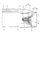
- FIG. 28 is a cross-sectional view of the centrifugal blower 40 according to the third embodiment.
- the centrifugal blower 1 according to the first embodiment is a one-sided suction type centrifugal blower having one suction port 6.
- the centrifugal blower 40 according to the third embodiment is a double suction type centrifugal blower having two suction ports 6.
- the same components as those in the first or second embodiment are designated by the same reference numerals, and the configurations different from those in the first or second embodiment will be mainly described.
- One of the two suction ports 6 is formed on the first side wall 8.
- a bell mouth 12 whose inner diameter is increased toward the outside of the scroll casing 4 is formed on the first side wall 8.
- the other of the two suction ports 6 is formed on the second side wall 9.
- a bell mouth 12 whose inner diameter is increased toward the outside of the scroll casing 4 is formed on the second side wall 9.
- the centrifugal blower 40 is provided with three protrusions 16 as in the case of the first embodiment.
- centrifugal blower 40 it is considered that pressure fluctuation occurs on the inner wall surfaces 11a and 11b as in the centrifugal blower 1 according to the first embodiment. Also in the third embodiment, the centrifugal blower 40 can reduce noise and obtain high fan efficiency by providing the protrusion 16.
- the number of protrusions 16 provided on the centrifugal blowers 1, 30 and 40 may be appropriately changed.
- the centrifugal blower 1 may be provided with one or more protrusions 16, and the number of protrusions 16 may be arbitrary.
- each of the above embodiments shows an example of the contents of the present disclosure.
- the configurations of each embodiment can be combined with other known techniques.
- the configurations of the respective embodiments may be appropriately combined. It is possible to omit or change a part of the configuration of each embodiment without departing from the gist of the present disclosure.
Landscapes
- Engineering & Computer Science (AREA)
- Mechanical Engineering (AREA)
- General Engineering & Computer Science (AREA)
- Structures Of Non-Positive Displacement Pumps (AREA)
Priority Applications (3)
| Application Number | Priority Date | Filing Date | Title |
|---|---|---|---|
| CN202080105801.8A CN116261629A (zh) | 2020-11-06 | 2020-11-06 | 离心送风机 |
| PCT/JP2020/041503 WO2022097265A1 (ja) | 2020-11-06 | 2020-11-06 | 遠心送風機 |
| JP2022560595A JP7387027B2 (ja) | 2020-11-06 | 2020-11-06 | 遠心送風機 |
Applications Claiming Priority (1)
| Application Number | Priority Date | Filing Date | Title |
|---|---|---|---|
| PCT/JP2020/041503 WO2022097265A1 (ja) | 2020-11-06 | 2020-11-06 | 遠心送風機 |
Publications (1)
| Publication Number | Publication Date |
|---|---|
| WO2022097265A1 true WO2022097265A1 (ja) | 2022-05-12 |
Family
ID=81457059
Family Applications (1)
| Application Number | Title | Priority Date | Filing Date |
|---|---|---|---|
| PCT/JP2020/041503 Ceased WO2022097265A1 (ja) | 2020-11-06 | 2020-11-06 | 遠心送風機 |
Country Status (3)
| Country | Link |
|---|---|
| JP (1) | JP7387027B2 (https=) |
| CN (1) | CN116261629A (https=) |
| WO (1) | WO2022097265A1 (https=) |
Families Citing this family (2)
| Publication number | Priority date | Publication date | Assignee | Title |
|---|---|---|---|---|
| KR102804616B1 (ko) * | 2023-12-28 | 2025-05-09 | 주식회사 금성풍력 | 와류저감구조를 갖는 원심형 송풍기 하우징 |
| CN119957561A (zh) * | 2025-04-09 | 2025-05-09 | 美诗儿(浙江)环境智能电器有限公司 | 基于复合风道协同降噪的大风量低噪送风装置 |
Citations (4)
| Publication number | Priority date | Publication date | Assignee | Title |
|---|---|---|---|---|
| JP2003227491A (ja) * | 2002-01-31 | 2003-08-15 | Toshiba Corp | ファン装置を有する電子機器 |
| JP2010229871A (ja) * | 2009-03-26 | 2010-10-14 | Mitsubishi Heavy Ind Ltd | 遠心ファン及び車両用空調装置 |
| WO2018128766A1 (en) * | 2017-01-04 | 2018-07-12 | Air Distribution Technologies Ip, Llc | Blower housing with fluted outlet |
| JP2019203418A (ja) * | 2018-05-22 | 2019-11-28 | サンデン・オートモーティブクライメイトシステム株式会社 | 送風機 |
Family Cites Families (6)
| Publication number | Priority date | Publication date | Assignee | Title |
|---|---|---|---|---|
| JP2515728Y2 (ja) * | 1990-07-31 | 1996-10-30 | アイシン精機株式会社 | 内燃機関用ウオーターポンプ |
| FR2800931B1 (fr) * | 1999-11-09 | 2004-01-23 | Alstom | Dispositif de ventilation et moteur electrique de traction ferroviaire equipe d'un tel dispositif |
| KR200442465Y1 (ko) * | 2007-09-12 | 2008-11-10 | 주식회사 두원공조 | 차량용 공조 유니트의 벤트 도어 |
| CN205641400U (zh) * | 2016-05-11 | 2016-10-12 | 广东美的制冷设备有限公司 | 空调器的风道组件及空调器 |
| SG10201707225UA (en) * | 2016-09-23 | 2018-04-27 | Sulzer Management Ag | Centrifugal pump for conveying a fluid |
| CN210832225U (zh) * | 2019-11-21 | 2020-06-23 | 广东美的制冷设备有限公司 | 空调室内机及空调器 |
-
2020
- 2020-11-06 CN CN202080105801.8A patent/CN116261629A/zh active Pending
- 2020-11-06 JP JP2022560595A patent/JP7387027B2/ja active Active
- 2020-11-06 WO PCT/JP2020/041503 patent/WO2022097265A1/ja not_active Ceased
Patent Citations (4)
| Publication number | Priority date | Publication date | Assignee | Title |
|---|---|---|---|---|
| JP2003227491A (ja) * | 2002-01-31 | 2003-08-15 | Toshiba Corp | ファン装置を有する電子機器 |
| JP2010229871A (ja) * | 2009-03-26 | 2010-10-14 | Mitsubishi Heavy Ind Ltd | 遠心ファン及び車両用空調装置 |
| WO2018128766A1 (en) * | 2017-01-04 | 2018-07-12 | Air Distribution Technologies Ip, Llc | Blower housing with fluted outlet |
| JP2019203418A (ja) * | 2018-05-22 | 2019-11-28 | サンデン・オートモーティブクライメイトシステム株式会社 | 送風機 |
Also Published As
| Publication number | Publication date |
|---|---|
| CN116261629A (zh) | 2023-06-13 |
| JPWO2022097265A1 (https=) | 2022-05-12 |
| JP7387027B2 (ja) | 2023-11-27 |
Similar Documents
| Publication | Publication Date | Title |
|---|---|---|
| JP4400686B2 (ja) | プロペラファン | |
| JP5737666B2 (ja) | 遠心式送風機または斜流送風機に用いられるインペラ | |
| JP5804348B2 (ja) | 遠心式送風機または斜流送風機に用いられるインペラ | |
| US20100189557A1 (en) | Impeller and fan | |
| JP2011089460A (ja) | ターボ型流体機械 | |
| CN206346936U (zh) | 离心式风扇 | |
| KR101252984B1 (ko) | 고속 원심 펌프용 유동 벡터 제어기 | |
| CN111577655B (zh) | 叶片及使用其的轴流叶轮 | |
| WO2015087909A1 (ja) | 遠心ファン | |
| CN101014772A (zh) | 多叶片风扇 | |
| JP5473497B2 (ja) | 多翼遠心ファンおよびそれを用いた空気調和機 | |
| WO2022097265A1 (ja) | 遠心送風機 | |
| CN100451349C (zh) | 多叶片送风机的叶轮以及具有该叶轮的多叶片送风机 | |
| JP2008138536A (ja) | 遠心送風機 | |
| JP2001032794A (ja) | 遠心ファン | |
| JP2009275524A (ja) | 軸流送風機 | |
| CN110939603A (zh) | 叶片及使用其的轴流叶轮 | |
| CN104781561A (zh) | 离心式风扇 | |
| JP5291382B2 (ja) | 多翼遠心ファン | |
| JP2006125229A (ja) | シロッコファン | |
| CN101208523B (zh) | 离心式多叶片风机 | |
| JP2010242597A (ja) | 軸流送風機及び空気調和機 | |
| CN222797760U (zh) | 一种叶轮、风机及油烟机 | |
| JP2000009083A (ja) | 羽根車 | |
| JP6265843B2 (ja) | 換気送風機 |
Legal Events
| Date | Code | Title | Description |
|---|---|---|---|
| 121 | Ep: the epo has been informed by wipo that ep was designated in this application |
Ref document number: 20960818 Country of ref document: EP Kind code of ref document: A1 |
|
| ENP | Entry into the national phase |
Ref document number: 2022560595 Country of ref document: JP Kind code of ref document: A |
|
| NENP | Non-entry into the national phase |
Ref country code: DE |
|
| 122 | Ep: pct application non-entry in european phase |
Ref document number: 20960818 Country of ref document: EP Kind code of ref document: A1 |