WO2022085632A1 - レーザ溶接方法およびレーザ溶接装置 - Google Patents
レーザ溶接方法およびレーザ溶接装置 Download PDFInfo
- Publication number
- WO2022085632A1 WO2022085632A1 PCT/JP2021/038448 JP2021038448W WO2022085632A1 WO 2022085632 A1 WO2022085632 A1 WO 2022085632A1 JP 2021038448 W JP2021038448 W JP 2021038448W WO 2022085632 A1 WO2022085632 A1 WO 2022085632A1
- Authority
- WO
- WIPO (PCT)
- Prior art keywords
- molten pool
- laser
- laser welding
- welding method
- sub
- Prior art date
- Legal status (The legal status is an assumption and is not a legal conclusion. Google has not performed a legal analysis and makes no representation as to the accuracy of the status listed.)
- Ceased
Links
Images







Classifications
-
- B—PERFORMING OPERATIONS; TRANSPORTING
- B23—MACHINE TOOLS; METAL-WORKING NOT OTHERWISE PROVIDED FOR
- B23K—SOLDERING OR UNSOLDERING; WELDING; CLADDING OR PLATING BY SOLDERING OR WELDING; CUTTING BY APPLYING HEAT LOCALLY, e.g. FLAME CUTTING; WORKING BY LASER BEAM
- B23K26/00—Working by laser beam, e.g. welding, cutting or boring
- B23K26/02—Positioning or observing the workpiece, e.g. with respect to the point of impact; Aligning, aiming or focusing the laser beam
- B23K26/06—Shaping the laser beam, e.g. by masks or multi-focusing
- B23K26/0604—Shaping the laser beam, e.g. by masks or multi-focusing by a combination of beams
- B23K26/0608—Shaping the laser beam, e.g. by masks or multi-focusing by a combination of beams in the same heat affected zone [HAZ]
-
- B—PERFORMING OPERATIONS; TRANSPORTING
- B23—MACHINE TOOLS; METAL-WORKING NOT OTHERWISE PROVIDED FOR
- B23K—SOLDERING OR UNSOLDERING; WELDING; CLADDING OR PLATING BY SOLDERING OR WELDING; CUTTING BY APPLYING HEAT LOCALLY, e.g. FLAME CUTTING; WORKING BY LASER BEAM
- B23K26/00—Working by laser beam, e.g. welding, cutting or boring
- B23K26/352—Working by laser beam, e.g. welding, cutting or boring for surface treatment
- B23K26/354—Working by laser beam, e.g. welding, cutting or boring for surface treatment by melting
-
- B—PERFORMING OPERATIONS; TRANSPORTING
- B23—MACHINE TOOLS; METAL-WORKING NOT OTHERWISE PROVIDED FOR
- B23K—SOLDERING OR UNSOLDERING; WELDING; CLADDING OR PLATING BY SOLDERING OR WELDING; CUTTING BY APPLYING HEAT LOCALLY, e.g. FLAME CUTTING; WORKING BY LASER BEAM
- B23K26/00—Working by laser beam, e.g. welding, cutting or boring
- B23K26/0006—Working by laser beam, e.g. welding, cutting or boring taking account of the properties of the material involved
-
- B—PERFORMING OPERATIONS; TRANSPORTING
- B23—MACHINE TOOLS; METAL-WORKING NOT OTHERWISE PROVIDED FOR
- B23K—SOLDERING OR UNSOLDERING; WELDING; CLADDING OR PLATING BY SOLDERING OR WELDING; CUTTING BY APPLYING HEAT LOCALLY, e.g. FLAME CUTTING; WORKING BY LASER BEAM
- B23K26/00—Working by laser beam, e.g. welding, cutting or boring
- B23K26/02—Positioning or observing the workpiece, e.g. with respect to the point of impact; Aligning, aiming or focusing the laser beam
- B23K26/06—Shaping the laser beam, e.g. by masks or multi-focusing
- B23K26/064—Shaping the laser beam, e.g. by masks or multi-focusing by means of optical elements, e.g. lenses, mirrors or prisms
-
- B—PERFORMING OPERATIONS; TRANSPORTING
- B23—MACHINE TOOLS; METAL-WORKING NOT OTHERWISE PROVIDED FOR
- B23K—SOLDERING OR UNSOLDERING; WELDING; CLADDING OR PLATING BY SOLDERING OR WELDING; CUTTING BY APPLYING HEAT LOCALLY, e.g. FLAME CUTTING; WORKING BY LASER BEAM
- B23K26/00—Working by laser beam, e.g. welding, cutting or boring
- B23K26/20—Bonding
- B23K26/21—Bonding by welding
- B23K26/24—Seam welding
-
- B—PERFORMING OPERATIONS; TRANSPORTING
- B23—MACHINE TOOLS; METAL-WORKING NOT OTHERWISE PROVIDED FOR
- B23K—SOLDERING OR UNSOLDERING; WELDING; CLADDING OR PLATING BY SOLDERING OR WELDING; CUTTING BY APPLYING HEAT LOCALLY, e.g. FLAME CUTTING; WORKING BY LASER BEAM
- B23K2101/00—Articles made by soldering, welding or cutting
- B23K2101/32—Wires
-
- B—PERFORMING OPERATIONS; TRANSPORTING
- B23—MACHINE TOOLS; METAL-WORKING NOT OTHERWISE PROVIDED FOR
- B23K—SOLDERING OR UNSOLDERING; WELDING; CLADDING OR PLATING BY SOLDERING OR WELDING; CUTTING BY APPLYING HEAT LOCALLY, e.g. FLAME CUTTING; WORKING BY LASER BEAM
- B23K2103/00—Materials to be soldered, welded or cut
- B23K2103/08—Non-ferrous metals or alloys
- B23K2103/10—Aluminium or alloys thereof
-
- B—PERFORMING OPERATIONS; TRANSPORTING
- B23—MACHINE TOOLS; METAL-WORKING NOT OTHERWISE PROVIDED FOR
- B23K—SOLDERING OR UNSOLDERING; WELDING; CLADDING OR PLATING BY SOLDERING OR WELDING; CUTTING BY APPLYING HEAT LOCALLY, e.g. FLAME CUTTING; WORKING BY LASER BEAM
- B23K2103/00—Materials to be soldered, welded or cut
- B23K2103/08—Non-ferrous metals or alloys
- B23K2103/12—Copper or alloys thereof
-
- B—PERFORMING OPERATIONS; TRANSPORTING
- B23—MACHINE TOOLS; METAL-WORKING NOT OTHERWISE PROVIDED FOR
- B23K—SOLDERING OR UNSOLDERING; WELDING; CLADDING OR PLATING BY SOLDERING OR WELDING; CUTTING BY APPLYING HEAT LOCALLY, e.g. FLAME CUTTING; WORKING BY LASER BEAM
- B23K2103/00—Materials to be soldered, welded or cut
- B23K2103/18—Dissimilar materials
- B23K2103/26—Alloys of Nickel and Cobalt and Chromium
-
- G—PHYSICS
- G02—OPTICS
- G02B—OPTICAL ELEMENTS, SYSTEMS OR APPARATUS
- G02B27/00—Optical systems or apparatus not provided for by any of the groups G02B1/00 - G02B26/00, G02B30/00
- G02B27/09—Beam shaping, e.g. changing the cross-sectional area, not otherwise provided for
- G02B27/0905—Dividing and/or superposing multiple light beams
-
- G—PHYSICS
- G02—OPTICS
- G02B—OPTICAL ELEMENTS, SYSTEMS OR APPARATUS
- G02B27/00—Optical systems or apparatus not provided for by any of the groups G02B1/00 - G02B26/00, G02B30/00
- G02B27/09—Beam shaping, e.g. changing the cross-sectional area, not otherwise provided for
- G02B27/0916—Adapting the beam shape of a semiconductor light source such as a laser diode or an LED, e.g. for efficiently coupling into optical fibers
-
- G—PHYSICS
- G02—OPTICS
- G02B—OPTICAL ELEMENTS, SYSTEMS OR APPARATUS
- G02B27/00—Optical systems or apparatus not provided for by any of the groups G02B1/00 - G02B26/00, G02B30/00
- G02B27/09—Beam shaping, e.g. changing the cross-sectional area, not otherwise provided for
- G02B27/0938—Using specific optical elements
- G02B27/0944—Diffractive optical elements, e.g. gratings, holograms
Definitions
- the present invention relates to a laser welding method and a laser welding apparatus.
- Patent Document 1 A technique for laser welding a plurality of metal members such as a flat wire is known (for example, Patent Document 1).
- one of the problems of the present invention is, for example, to obtain an improved new laser welding method and laser welding apparatus capable of suppressing the generation of voids.
- the laser welding method of the present invention targets a laser beam including, for example, a main power region including at least one main beam and a sub power region including at least one sub beam having a power density smaller than that of the main beam.
- a laser welding method for welding an object by irradiating the object with a laser beam which comprises a step of forming a molten pool by irradiating the object with the laser beam and a step of solidifying the molten pool.
- the sub-beam irradiates the object so that the void formed in the molten pool escapes to the outside of the molten pool before the molten pool solidifies.
- the number of voids in the lower half of the weld formed by solidifying the molten pool is equal to or less than the number of voids in the upper half.
- the laser beam may be irradiated.
- the main power region may be located inside the outer edge of the sub power region.
- the sub-power region may include a plurality of sub-beams as the at least one sub-beam, and the main beam may be surrounded by the plurality of sub-beams.
- the sub-power region may include one sub-beam surrounding the main power region as the at least one sub-beam.
- the laser welding method may include a step of temporarily maintaining the molten pool in a molten state by irradiating the molten pool with the laser beam after the step of forming the molten pool.
- the power of the laser beam in the step of temporarily maintaining the molten pool in a molten state, may be lower than in the step of forming the molten pool.
- the power of the main beam in the step of temporarily maintaining the molten pool in a molten state, the power of the main beam may be lower than in the step of forming the molten pool.
- the dent generated on the surface of the molten pool due to the irradiation of the laser beam in the step of temporarily maintaining the molten pool in a molten state is the laser beam in the step of forming the molten pool. It may be shallower than the dent formed on the surface of the molten pool by the irradiation of.
- the power density of the laser beam on the surface of the molten pool is 107 [W / cm 2 ] or less. May be good.
- the power density of the laser beam on the surface of the molten pool is 106 [W / cm 2 ] or less. May be good.
- the main beam in the step of forming the molten pool, the main beam is irradiated, and in the step of temporarily maintaining the molten pool in a molten state, even if the irradiation of the main beam is stopped. good.
- the wavelength of the main beam and the wavelength of the sub beam may be the same.
- the wavelength of the main beam and the wavelength of the sub beam may be different.
- the wavelength of the main beam may be 800 [nm] or more and 1200 [nm] or less, and the wavelength of the sub beam may be 550 [nm] or less.
- a plurality of beams included in at least one of the main power region and the sub power region may be formed by a beam shaper.
- the object may be swept while irradiating the object with the laser beam.
- At least a part of the sub power region may be located behind the main power region in the sweep direction of the laser light with respect to the object.
- the laser beam may be swept linearly.
- the laser beam may be applied to a fixed point in the step of temporarily maintaining the molten pool in a molten state.
- the laser beam in the step of temporarily maintaining the molten pool in a molten state, is emitted in a path curved around the center of the molten pool when viewed in the irradiation direction of the laser beam. It may be swept.
- the object is made of any one of a copper-based metal material, an aluminum-based metal material, a nickel-based metal material, an iron-based metal material, and a titanium-based metal material. May be good.
- the molten pool has a first end portion in a first direction of a first member made of a metal material and a second one intersecting the first direction with respect to the first member.
- the distance of the second end portion of the second member made of a metal material adjacent to the direction along the first direction from the second end portion in the first direction is 0 or more. It may be formed so as to be hung between the second end portion arranged so as to be.
- the member constituting the object may be a flat wire conductor.
- the laser welding apparatus of the present invention includes, for example, a laser oscillator and an optical head that irradiates an object with laser light emitted from the laser oscillator, and the laser light includes at least one main beam and the main beam. It contains at least one sub-beam having a power density lower than that of the beam, and is irradiated so as to form a molten pool on the object. The object is irradiated so as to escape from the molten pool before solidifying.
- the laser welding apparatus may include a sensor that detects the temperature of the molten pool and an output unit that outputs information indicating welding quality based on the detection result of the sensor.
- the laser welding device includes a sensor that detects the temperature of the molten pool, a variable mechanism that can change the irradiation state of the laser beam, and a control unit that controls the operation of the variable mechanism based on the detection result of the sensor. , May be provided.
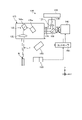
- FIG. 1 is an exemplary schematic configuration diagram of the laser welding apparatus of the first embodiment.
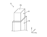
- FIG. 2 is an exemplary and schematic side view of the object of the laser welding method of the embodiment before welding.
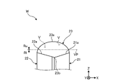
- FIG. 3 is an exemplary and schematic side view of the object of the laser welding method of the embodiment after welding.
- FIG. 4 is an explanatory diagram showing the concept of the principle of the diffractive optical element included in the laser welding apparatus of the embodiment.
- FIG. 5 is a schematic diagram showing an example of a beam (spot) on the surface of an object of the laser welding apparatus of the embodiment.
- FIG. 6 is a schematic diagram showing an example of a beam (spot) on the surface of an object of the laser welding apparatus of the embodiment.
- FIG. 1 is an exemplary schematic configuration diagram of the laser welding apparatus of the first embodiment.
- FIG. 2 is an exemplary and schematic side view of the object of the laser welding method of the embodiment before welding.
- FIG. 3 is an exemplary and schematic side view of the object of the laser welding method of the embodiment after
- FIG. 7 is a schematic diagram showing an example of a beam (spot) on the surface of an object of the laser welding apparatus of the embodiment.
- FIG. 8 is a schematic diagram showing an example of a beam (spot) on the surface of an object of the laser welding apparatus of the embodiment.
- FIG. 9 is an exemplary and schematic side view of an object in the process of forming a molten pool by the laser welding method of the embodiment.
- FIG. 10 is an exemplary and schematic plan view of a laser beam sweep path on an object by the laser welding method of the embodiment.
- FIG. 11 is an exemplary schematic diagram showing changes over time in the temperature of the molten pool and the output of the laser device according to the laser welding method of the first embodiment.
- FIG. 12 is an exemplary and schematic perspective view of a flat wire including a member as an object of the laser welding method of the embodiment.
- FIG. 13 is an exemplary and schematic side view of the weld formed by the laser welding method of the embodiment.
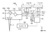
- FIG. 14 is an exemplary schematic configuration diagram of the laser welding apparatus of the second embodiment.
- FIG. 15 is a graph showing the light absorption rate of each metal material with respect to the wavelength of the irradiated laser light.
- FIG. 16 is an exemplary schematic diagram showing changes over time in the temperature of the molten pool and the output of the laser device according to the laser welding method of the second embodiment.
- FIG. 17 is an exemplary and schematic side view of an object in the process of maintaining a molten pool by the laser welding method of the second embodiment.
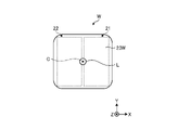
- FIG. 18 is a schematic plan view showing an example of the irradiation position of the laser beam on the molten pool by the laser welding method of the second embodiment.
- FIG. 19 is a schematic plan view showing an example of a laser beam sweep path on a molten pool by the laser welding method of the second embodiment.
- FIG. 20 is a schematic plan view showing an example of a laser beam sweep path on a molten pool by the laser welding method of the second embodiment.
- FIG. 21 is an exemplary block diagram of the laser welding apparatus of the embodiment.
- FIG. 22 is an exemplary flowchart showing a processing procedure for outputting inspection results by the laser welding apparatus of the embodiment.
- FIG. 23 is an exemplary flowchart showing a processing procedure for void suppression control by the laser welding apparatus of the embodiment.
- the direction X is represented by an arrow X
- the direction Y is represented by an arrow Y
- the direction Z is represented by an arrow Z.
- Direction X, direction Y, and direction Z intersect and are orthogonal to each other.
- the Z direction is a direction in which a plurality of members serving as the object W extend.
- the Z direction is substantially vertically above, but may be inclined with respect to the vertically above.
- FIG. 1 is a diagram showing a schematic configuration of the laser welding apparatus 100 of the first embodiment.
- the laser welding device 100 includes a laser device 110, an optical head 120, an optical fiber 130, a drive mechanism 140, a sensor 150, and a controller 200.
- the laser welding device 100 irradiates the surface of the object W to be laser welded with the laser beam L.
- the object W is partially melted by the energy of the laser beam L, cooled and solidified, so that the object W is welded.
- the object W has a plurality of members, and the plurality of members are joined by laser welding.
- the plurality of members to be the object W are, for example, a copper-based metal material such as copper or a copper alloy, an aluminum-based metal material such as aluminum or an aluminum alloy, or a nickel-based material such as nickel or a nickel alloy. It can be made of metal materials such as iron, iron-based metal materials such as iron and iron alloys, and titanium-based metal materials such as titanium and titanium alloys.
- the plurality of members may be made of the same metal material or may be made of different metal materials from each other.
- the plurality of members serving as the object W may or may not be conductors.
- the laser device 110 has a laser oscillator, and as an example, it is configured to be able to output a single mode laser beam having a power of several kW.
- the laser device 110 may be configured to have, for example, a plurality of semiconductor laser elements inside, and to output a multimode laser beam having a power of several kW as the total output of the plurality of semiconductor laser elements. ..
- the laser device 110 may have various laser light sources such as a fiber laser, a YAG laser, and a disk laser. Further, the laser device 110 outputs, for example, a laser beam having a wavelength of 400 [nm] or more and 1200 [nm] or less.
- the optical fiber 130 optically connects the laser device 110 and the optical head 120. In other words, the optical fiber 130 guides the laser light output from the laser device 110 to the optical head 120.
- the optical fiber 130 is configured to propagate the single-mode laser beam.
- the M2 beam quality of the single mode laser beam is set to 1.3 or less.
- M 2 beam quality can also be referred to as M 2 factor.
- the optical head 120 is an optical device for irradiating the laser beam input from the laser device 110 toward the object W.
- the optical head 120 includes a collimating lens 121, a condenser lens 122, a mirror 123, a DOE 125 (diffractive optical element), and a galvano scanner 126.
- the collimating lens 121, the condenser lens 122, the mirror 123, the DOE125, and the galvano scanner 126 may also be referred to as optical components.
- the collimating lens 121 collimates the laser beam input via the optical fiber 130, respectively.
- the collimated laser beam becomes parallel light.
- the mirror 123 reflects the laser beam that has become parallel light by the collimated lens 121 and directs it to the galvano scanner 126.
- a DOE 125 is provided between the mirror 123 and the galvano scanner 126. DOE125 will be described later.
- the galvano scanner 126 has a plurality of mirrors 126a and 126b, and by controlling the angles of the plurality of mirrors 126a and 126b, the emission direction of the laser beam L from the optical head 120 is switched, thereby switching the target.
- the irradiation position of the laser beam L can be changed on the surface of the object W.
- the angles of the mirrors 126a and 126b are changed by, for example, a motor (not shown) controlled by the controller 200, respectively.
- the laser beam L can be swept on the surface of the object W.
- the condenser lens 122 collects the laser beam as parallel light coming from the galvano scanner 126 and irradiates the object W as the laser beam L (output light).
- optical components included in the optical head 120 are not limited to these, and the optical head 120 may include other optical components.
- the drive mechanism 140 changes the relative position of the optical head 120 with respect to the object W.
- the drive mechanism 140 includes, for example, a rotation mechanism such as a motor, a deceleration mechanism for decelerating the rotation output of the rotation mechanism, a motion conversion mechanism for converting the rotation decelerated by the deceleration mechanism into linear motion, and the like.
- the controller 200 can control the drive mechanism 140 so that the relative positions of the optical head 120 with respect to the object W in the X direction, the Y direction, and the Z direction change.
- the drive mechanism 140 can change (switch) (switch) the object W to be laser welded among the plurality of objects W supported by the support mechanism (not shown).
- the drive mechanism 140 can change the irradiation position of the laser beam L on the object W. Further, the drive mechanism 140 can be used to change the irradiation point as the irradiation direction of the laser beam with respect to the object W is changed. Further, the drive mechanism 140 can change the irradiation position while the laser beam L is irradiated on the surface of the object W. That is, the drive mechanism 140 can sweep the laser beam L on the surface of the object W.
- the sensor 150 is a sensor that detects the temperature of the molten pool formed on the object W by irradiation with the laser beam L, and is, for example, a radiation thermometer or an infrared thermography camera.
- the controller 200 controls the operation of the laser device 110, the drive mechanism 140, and the galvano scanner 126 based on the detection result of the sensor 150.
- the laser device 110, the drive mechanism 140, and the galvano scanner 126 can change the irradiation state of the laser beam L irradiated from the optical head 120 to the object W, respectively. That is, the laser device 110, the drive mechanism 140, and the galvano scanner 126 are examples of variable mechanisms and can also be referred to as controlled objects by the controller 200.
- FIG. 2 is a side view showing the state of the object W before welding.
- the object W has two members 20 (21, 22). Both of the two members 20 are made of a metallic material.
- Both of the two members 20 extend in the Z direction and have end portions 20a (21a, 22a) in the Z direction.
- the end portion 20a extends so as to intersect the Z direction. That is, the end portion 20a extends in the X direction and also in the Y direction.
- the Z direction is an example of the first direction.
- the two members 20 are adjacent to each other in the X direction intersecting the Z direction and are arranged in the X direction.
- a gap g is formed between the side surfaces 21b and 22b (20b) facing each other in the X direction.
- the size of the gap g is 0 or more. That is, the two members 20 may be in contact with each other at least partially.
- the X direction is an example of the second direction.
- the deviation ⁇ of the end portion 21a of the member 21 with respect to the end portion 22a of the member 22 in the Z direction is 0 or more. That is, of the two members 20 having such a relative positional relationship, the end portion 21a that is at the same position as the end portion 22a in the Z direction or is displaced in the Z direction with respect to the end portion 22a is the first.
- the end portion 22a which is an example of one end portion and is displaced in the direction opposite to the end portion 21a in the Z direction, is an example of the second end portion.
- the member 21 having the end portion 21a is an example of the first member
- the member 22 having the end portion 22a is an example of the second member.
- the member 21 (first member) may also be referred to as a member relatively protruding in the Z direction
- the member 22 (second member) may also be referred to as a member relatively retracted in the Z direction.
- the optical head 120 irradiates the laser beam L toward the end portion 20a.
- the irradiation direction of the laser beam L is a direction opposite to the Z direction or a direction inclined with respect to the opposite direction to the Z direction.
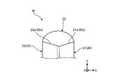
- FIG. 3 is a side view showing the state of the object W after welding.
- the welded portion 23 is a molten pool formed in a state of being hung between the two end portions 20a and cooled and solidified.
- the molten pool which is a fluid metal material, has a shape bulging in the Z direction due to surface tension.
- the welded portion 23 in which the molten pool is solidified also has a shape bulging in the Z direction.
- the welded portion 23 mechanically connects the two members 21 and 22. Further, when the two members 21 and 22 are made of a conductive metal, the welded portion 23 electrically connects the two members 21 and 22.
- the optical head 120 has a DOE 125.
- the shape of the beam of the laser beam (hereinafter referred to as the beam shape) is formed.
- FIG. 4 is an explanatory diagram showing the concept of the principle of DOE125.
- the DOE 125 has, for example, a configuration in which a plurality of diffraction gratings 125a having different periods are superposed.
- the DOE 125 can form a beam shape by bending or superimposing parallel light in a direction affected by each diffraction grating 125a.
- DOE125 may also be referred to as a beam shaper.
- the DOE125 divides the collimated laser beam into a plurality of beams.
- 5 to 8 are diagrams showing an example of a beam of laser light L formed on the surface Wa of the object W, respectively.
- the beam B1 is shown by a solid line and the beam B2 is shown by a broken line.
- the optical head 120 can output a laser beam including a plurality of beams having various arrangements.
- DOE125 is an example of a beam shaper.
- DOE125 divides the laser beam into a plurality of beams.
- the plurality of divided beams include at least one beam B1 and at least one beam B2.
- the beam B2 is a beam having a smaller power density than the beam B1.
- the beam B1 is an example of a main beam
- the beam B2 is an example of a sub beam. Further, the beam B1 forms a main power region, and the beam B2 forms a sub power region.
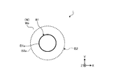
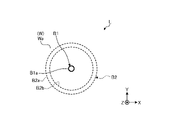
- one spot of the beam B1 and a spot of the beam B2 wider than the beam B1 are formed on the surface Wa.
- the beam B1 and the outer edge B1a of the beam B1 are located inside the outer edge B2a of the beam B2.
- the beam B1 and the beam B2 may be arranged concentrically or eccentrically. Further, the outer edge B1a may be inscribed in the outer edge B2a.
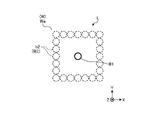
- one spot of the beam B1 and a plurality of spots of the beam b2 surrounding the beam B1 are formed on the surface Wa.
- the beams b2 are arranged in a substantially annular shape.
- the beam b2 is an example of a sub-beam, and a sub-power region is formed by a plurality of beams b2.
- one spot of the beam B1 and a plurality of spots of the beam b2 surrounding the beam B1 are formed on the surface Wa.
- the beams b2 are arranged in a substantially quadrangular shape, that is, along the sides of a virtual quadrangle.
- the beam b2 is an example of a sub-beam, and a sub-power region is formed by a plurality of beams b2.
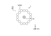
- one spot of the beam B1 and one spot of the annular beam B2 surrounding the beam B1 are formed on the surface Wa.
- the beam B1 and the outer edge B1a of the beam B1 are located inside the inner edge B2b of the beam B2.
- the beam B2 has an annular shape, but is not limited to this, and may have another shape such as a rectangular frame shape. Further, a part of the beam B2 may be cut off.
- FIG. 9 is a side view of the object W in the step of forming the molten pool 23W (hereinafter referred to as a forming step) of the laser welding method.
- the laser light L radiated to the end 21a of the member 21 is referred to as the laser light L1
- the laser light L radiated to the end 22a of the member 22 is referred to as the laser light L2.
- these laser beams L1 and L2 are both emitted from the same optical head 120.
- the molten pool 23W is formed on the ends 21a and 22a in a state of being hung between the ends 21a and 22a.
- the molten pool 23W is formed by melting the metal materials of the members 21 and 22.
- the molten pool 23W contains the metallic material of the members 21 and 22. Further, the molten pool 23W is in a state of having fluidity.
- a void V may be formed inside the molten pool 23W. Since the void V leads to a decrease in the welding strength due to the welded portion 23, it is preferable that the void V does not remain in the solidified state.
- the laser beam L may be swept in the irradiated state.
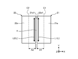
- FIG. 10 is an explanatory diagram showing an example of a sweep path of the laser beams L1 and L2 (L) at the ends 21a and 22a.
- the laser beam L1 is swept linearly in the Y direction intersecting the X direction in the region A1 on the end 22a side of the center C1 in the X direction of the end 21a.
- the laser beam L2 is swept linearly in the Y direction intersecting the X direction in the region A2 on the end 21a side of the center C2 in the X direction of the end 22a.
- the sweeping of the laser beams L1 and L2 may be performed a plurality of times, respectively.
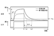
- FIG. 11 is a diagram showing changes over time in the temperature of the molten pool 23W and the output of the laser beam from the laser device 110 in the welding according to the present embodiment.
- the change with time in the laser welding in the present embodiment is shown by a solid line.
- the change with time in laser welding when a similar welded portion 23 is obtained for the same object W by irradiation with a single beam laser beam is shown by a broken line. There is.
- the laser device 110 starts the output at the time t0 and stops the output at the time t1.
- the molten pool 23W is naturally cooled in a normal temperature atmosphere, and the temperature of the molten pool 23W gradually decreases accordingly.
- the temperature Tr of the molten pool 23W drops to the melting point Tm at time ter, as shown by the broken line.
- the temperature T1 of the molten pool 23W drops to the melting point Tm at the time te1 later than the time ter, as shown by the solid line.
- the molten pool 23W is in a molten state at a temperature higher than the melting point Tm.
- the temperature T1 is the temperature in the forming step of the molten pool 23W, and as an example, it is the maximum temperature in the forming step.
- the temperature T1 of the molten pool 23W when forming the molten pool 23W that is, the temperature of the molten pool 23W in a state where the laser device 110 emits laser light.
- T1 is higher than the temperature Tr of the molten pool 23W in the case of the prior art.
- the laser beam L has, for example, a plurality of beams B1 and B2 as exemplified in FIGS. 5 to 7.
- T1-Tm can be made larger than in the case of a single beam.
- the temperature T1 of the molten pool 23W can be further increased within a range that does not affect the welding quality, and as a result, the descent time until the temperature T1 of the molten pool 23W drops to the melting point Tm.
- the temperature drop rate after the time t1 is slower (lower) than that of the conventional technique.
- the laser beam L has, for example, beams B1 and B2 as exemplified in FIGS. 5 to 7. That is, since the laser beam L has the beam B2 having a lower power density, it is more gradual in a wider range of the object W than in the case of a single beam in the state where the molten pool 23W is formed. It is possible to form a flexible temperature distribution. As a result, it is possible to prevent the object W from being rapidly cooled after the irradiation of the laser beam L is stopped. Therefore, according to the present embodiment, also in this respect, the descent time ⁇ t1 until the temperature T1 of the molten pool 23W drops to the melting point Tm can be made longer than in the case of a single beam.
- Void V which is a bubble in the molten pool 23W, rises in the molten pool 23W in the molten state of the molten pool 23W, that is, in a state of having fluidity, and goes out from the molten pool 23W. Therefore, the longer the molten pool 23W is in the molten state, the more void V is discharged to the outside of the molten pool 23W, and the amount of void V remaining in the solidified welded portion 23 is reduced.
- the descent time ⁇ t1 becomes longer than in the case of a single beam. , The molten pool 23W can be maintained in a molten state for a longer period of time. Therefore, according to the present embodiment, it is possible to form the welded portion 23 having a smaller void V.
- the beams B1 and B2 are set to the arrangement and power density as exemplified in FIGS. 5 to 7 and as described above, so that a longer time is required as compared with the case of a single beam. It was confirmed that the molten state of the molten pool 23W was obtained and the void V could be further reduced.
- the temperature T1 of the molten pool 23W required for at least one void V to escape from the molten pool 23W to the outside of the molten pool 23W, and the descent time ⁇ t1 ( te1-) from the temperature T1 to the melting point Tm.
- the arrangement and power density of the beams B1 and B2 can be set so as to secure t1).
- the temperature T1 and the descent time ⁇ t1 have different values depending on the material, the heat dissipation of the environment, the atmospheric temperature, and the like.
- FIG. 12 is a perspective view of the flat wire 10 including the member 20.
- the member 20 is a core wire (internal conductor) of a flat wire 10 as shown in FIG.
- the flat wire 10 has a member 20 and a coating 30 of the member 20.
- the member 20 is made of a conductive metal material.
- the shape of the cross section of the member 20 orthogonal to the extending direction is substantially quadrangular.
- the coating 30 has an insulating property and is made of, for example, enamel, a synthetic resin material, or the like.
- the coating 30 may have an enamel layer and an extruded resin layer surrounding the enamel layer.
- the laser welding device 100 is applied to welding end portions 20a of a member 20 as a core wire of such a flat wire 10.
- the coating 30 is removed in the vicinity of the extending ends of the two flat wire 10. Then, as shown in FIG. 2, the end portions 20a of the two members 20 arranged adjacent to each other in a posture facing the same direction (extending direction) are welded by the laser welding device 100.
- the flat wire 10 may form a coil provided in a rotary electric machine such as a motor or a motor generator.
- the laser welding method by the laser welding apparatus 100 of the present embodiment can be applied to welding the ends of coils adjacent to each other set on the stator core.
- the member 20 to be the object W is not limited to the core wire of the flat wire 10, and as shown in FIG. 2, they extend in the Z direction, are adjacent to each other in the X direction, and the end portions 20a are close to each other. Any member may be used as long as it has side surfaces 20b facing each other in the X direction.
- the member 20 may be a plate-shaped member or a wire rod.
- FIG. 13 is an exemplary side view of the welded portion 23.
- the irradiation condition of the laser beam L is such that the number of voids V in the lower half Rl of the welded portion 23 is equal to or less than the number of voids V in the upper half Ru of the welded portion 23.
- the irradiation conditions of the beam B2 (secondary beam) are set.
- the virtual plane VP passes through an intermediate position between the upper end 23a of the welded portion 23 in the vertical direction at the time of welding and solidification of the welded portion 23 and the lower end 23b in the vertical direction, and at the time of welding and solidification.
- the upper half Ru is a portion above the virtual plane VP and is a portion opposite to the lower half Rl with respect to the virtual plane VP. Further, the lower half Rl is a portion of the welded portion 23 below the virtual plane VP and opposite to the upper half Ru with respect to the virtual plane VP.
- the void V moves upward. Therefore, when the molten state of the molten pool 23W is maintained by irradiation with the laser beam L (beam B2), the void V generated in the lower half Rl rises and moves out of the upper half Ru or the molten pool 23W and escapes.
- the void V that was not removed remains mainly in the upper half Ru.
- a state is obtained in which the number of voids V in the lower half Rl is equal to or less than the number of voids V in the upper half Ru. That is, in the welded portion 23, the state in which the number of voids V in the lower half Rl is equal to or less than the number of voids V in the upper half Ru is a state in which the effect of reducing the voids V by irradiation of the beam B2 is obtained. It can be said that.
- the required bonding strength and conductivity can be obtained by appropriately setting the laser beam L, particularly the beam B2, so that the number of voids V in the lower half Rl is equal to or less than the number of voids V in the upper half Ru. It is possible to form a welded portion 23 having a smaller number of voids V.
- the number of voids V in the upper half Ru is 2, and the number of voids V in the lower half Rl is 0, but the number of voids V is not limited to this example.
- the beam B2 (secondary beam) is at least among the voids V formed in the molten pool 23W before the molten pool 23W solidifies.
- the object W is irradiated so that one void V escapes from the molten pool 23W.
- a molten pool 23W is formed in the object W, and at least one void V among the voids V formed in the molten pool 23W is the void V.
- the temperature of the molten pool 23W is set to change with time so that the molten pool 23W can escape to the outside.
- the void V in the welded portion 23 can be further reduced, and the decrease in the strength of the welded portion 23 due to the void V can be suppressed.
- FIG. 14 is a diagram showing a schematic configuration of the laser welding apparatus 100A of the second embodiment.
- the laser welding apparatus 100A is different from the first embodiment in that the laser welding apparatus 100A includes a plurality of laser apparatus 111, 112 (110) and a sensor 150 provided in the optical head 120A. are doing.
- the optical head 120A is different from the first embodiment in that the optical head 120A has the collimating lens 121-2, the filters 124, 127, and the mirror 128.
- the laser devices 111 and 112 each have a laser oscillator.
- the laser devices 111 and 112 output laser light having different wavelengths.
- the laser device 111 outputs, for example, the first laser beam having a wavelength of 800 [nm] or more and 1200 [nm] or less.
- the laser device 111 may also be referred to as a first laser device, and the laser oscillator included in the laser device 111 may also be referred to as a first laser oscillator.
- the laser device 112 outputs a second laser beam having a wavelength of 550 [nm] or less.
- the laser device 112 may also be referred to as a second laser device, and the laser oscillator included in the laser device 112 may also be referred to as a second laser oscillator.
- the laser device 112 has a semiconductor laser (element) as a laser light source.
- the laser device 112 may output a laser beam having a wavelength of 400 [nm] or more and 500 [nm] or less.
- the optical head 120A With the installation of the laser device 112, the optical head 120A is provided with a filter 124.
- the first laser beam reflected by the mirror 123 travels in the opposite direction to the Z direction and heads toward the filter 124.
- the mirror 123 is not required in the configuration in which the first laser beam is input so as to travel in the direction opposite to the Z direction in the optical head 120A.
- the filter 124 is, for example, a high-pass filter that transmits the first laser beam and reflects the second laser beam without transmitting it.
- the first laser beam passes through the filter 124 and is directed to the galvano scanner 126.
- the filter 124 reflects the second laser beam that has become parallel light by the collimated lens 121-2.
- the second laser beam reflected by the filter 124 also goes to the galvano scanner 126.
- the filter 127 is provided between the mirror 123 and the filter 124.
- the filter 127 transmits the first laser beam from the mirror 123 toward the filter 124, and directs the light coming from the surface Wa of the object W (see FIGS. 5 to 7) and passing through the filter 124 toward the mirror 128. reflect.
- the light reflected by the mirror 128 is input to the sensor 150.
- the sensor 150 can capture an image on the surface Wa.
- the sensor 150 is, for example, an infrared thermography camera, and can detect the temperature distribution on the surface Wa.
- DOE125 is provided.
- the DOE 125 is arranged between the collimating lens 121-2 and the filter 124 to form a beam of second laser light.
- the optical head 120A may have a DOE that forms a beam of the first laser beam.
- the laser welding apparatus 100A may be provided with the sensor 150 as in the first embodiment, instead of the sensor 150. Further, the laser welding apparatus 100 of the first embodiment may include a sensor 150 attached to the body of the optical head 120 as in the present embodiment.
- FIG. 15 is a graph showing the light absorption rate of each metal material with respect to the wavelength of the laser light L to be irradiated.
- the horizontal axis of the graph of FIG. 15 is the wavelength, and the vertical axis is the absorption rate.
- FIG. 15 shows the relationship between wavelength and absorptance for aluminum (Al), copper (Cu), gold (Au), nickel (Ni), silver (Ag), tantalum (Ta), and titanium (Ti). It is shown.
- blue or green laser light (second laser) is used rather than using a general infrared (IR) laser light (first laser light). It can be understood that the energy absorption rate is higher when light) is used. This feature is remarkable in copper (Cu), gold (Au), and the like.
- the laser beam L having the beam B1 generated by the first laser beam from the laser device 111 and the beam B2 generated by the second laser beam from the laser device 112 is applied to the object W. Can be irradiated.
- the first laser beam having a wavelength of 800 [nm] or more and 1200 [nm] or less is output
- the second laser beam having a wavelength of 500 [nm] or less is output.
- heat energy can be efficiently given to the molten pool 23W, so that the molten pool 23W is more efficiently suppressed from being locally cooled and solidified. be able to.
- the time zone in which each of the first and second laser beams is emitted is independently controlled as described later. You may.
- At least a part of the second laser beam may be irradiated to the rear of the sweep direction of the laser beam L with respect to the first laser beam. At this time, at least a part of the region irradiated with the first laser beam and the region irradiated with the second laser beam may overlap.
- the controller 200 can control the operation of the laser devices 111 and 112, respectively. That is, the time zone in which the laser device 111 emits the first laser beam, that is, the beam B1 and the time zone in which the laser device 112 emits the second laser beam, that is, the beam B2 can be independently controlled. can.
- FIG. 16 is a diagram showing changes over time in the temperature of the molten pool 23W and the output of the laser light from the laser devices 111, 112 (110) in the welding according to the present embodiment.
- the notation of temperature is the same as that of FIG. 11 of the first embodiment.
- the change with time of the output of the first laser beam main beam
- the change with time of the output of the second laser beam secondary beam
- the laser device 111 starts the output at the time t0 and stops the output at the time t2.
- the laser device 112 starts the output at the time t0, but stops the output at the time tk that exceeds the time t2. Then, after the time tk, the molten pool 23W is naturally cooled in a normal temperature atmosphere, and the temperature of the molten pool 23W gradually decreases accordingly.
- the laser beam L includes beams B1 and B2.
- the molten pool 23W is formed by irradiating the object W with the laser beam L during this period. That is, in the laser welding method of the present embodiment, the step of forming the molten pool 23W is executed from the time t0 to the time t2.
- the laser beam L does not include the beam B1 but contains only the beam B2.
- the output of the laser beam L is lower than that between the time t0 including the beams B1 and B2 and the time t2.
- the laser beam L is set so that the molten state of the molten pool 23W is maintained by irradiating the molten pool 23W with the laser beam L. That is, in the laser welding method of the present embodiment, the laser beam L and the beam B1 such as the shape, arrangement, power density, irradiation position, sweep path, and sweep speed of the beams B1 and B2 are formed from time t2 to time tk.
- a step of temporarily maintaining the molten state of the molten pool 23W while suppressing the further formation and expansion of the molten pool 23W and the solidification of the molten pool 23W by appropriately setting the specifications regarding the irradiation of B2 (hereinafter, maintenance).
- the process) is executed.
- the maintenance process may also be referred to as an extension process.
- FIG. 17 is a side view of the object W in the maintenance process of the laser welding method.
- the laser beams L1 and L2 (L) are applied to the molten pool 23W. Further, even in the maintenance step, the laser beams L1 and L2 (L) can be swept while being linearly irradiated as shown in FIG. The irradiation position, the sweep path, the sweep speed, and the like may be the same as or different from those in the forming step.
- the laser beams L1 and L2 (L) may be applied to a wider range than the forming step.
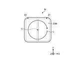
- FIGS. 18 to 20 are plan views illustrating the irradiation position or sweep path of the laser beam L to the molten pool 23W in the maintenance step, that is, a view seen in the irradiation direction of the laser beam L.
- FIG. 18 shows a case where the laser beam L irradiates the center C of the molten pool 23W in a plan view
- FIG. 19 shows a case where the laser beam L is swept by a curved path around the center C.
- FIG. Reference numeral 20 indicates a case where the laser beam L is swept by a curved path around the center C.
- the number of laps in the sweep may be one, less than one, or two or more.
- the laser beam L may be continuously or intermittently irradiated.
- the laser beam L may be intermittently irradiated to the center C, and the laser beam L may be intermittently irradiated while being swept by the locus as shown in FIGS. 19 and 20. May be good. Further, the laser beam L may not be intermittently irradiated to one point as shown in FIG.
- a dent (a dent in the opposite direction in the Z direction, hereinafter simply a dent) is formed in the region of the surface of the molten pool 23W irradiated with the laser beam L. ) Occurs.
- the dent caused by the irradiation of the laser beam L in the maintenance step is shallower than the dent caused by the irradiation of the laser beam L in the step of forming the molten pool 23W, there is less spatter and void V. It turned out that high quality welding is possible.
- the dent becomes deeper according to the power density. Therefore, it means that the power density on the surface of the molten pool 23W of the laser beam L in the maintenance step is preferably lower than the power density on the surface of the molten pool 23W in the step of forming the molten pool 23W.
- the depth of such a dent can be measured in FIG. 14 by configuring the sensor 150 as a sensor for optical coherence tomography (OCT).
- OCT optical coherence tomography
- the dent generated in the maintenance step is shallower than the dent generated in the step of forming the molten pool 23W, or the dent is equal to or less than a predetermined value in the maintenance step.
- the power of the laser device 110 may be controlled so as to be.
- Table 1 shows the welding quality determination results based on the number of voids V in the welded portion 23 according to the range of the power density, which was obtained from the results of experiments on a plurality of samples having different power densities of the laser beam L. Shows. In measuring the number of voids V, those having a diameter of 100 [ ⁇ m] or more in one cross section viewed from the side surface of the sample after welding are counted.
- ⁇ indicates that the number of voids V is 10 or less (excellent), ⁇ indicates that the number of voids V is more than 10 and 20 or less (good), and ⁇ indicates that the number of voids V is 20. When it is more and less than 30 (possible), and x indicates a case where the number of voids V is more than 30 (defective).
- the power density Pd is preferably 107 [W / cm 2] or less, and more preferably 10 6 [ W / cm 2 ] or less. It can be presumed that this is because if the power density Pd is too large, a keyhole is formed in the molten pool 23W, and the spatter and thus the void V increase.
- the power density Pd is preferably larger than 10 3 [W / cm 2 ], and more preferably larger than 10 4 [W / cm 2 ]. It can be presumed that if the power density Pd is too small, the molten state of the molten pool 23W cannot be sufficiently maintained, and the molten pool 23W solidifies earlier.
- the molten pool 23W is irradiated with laser beams L1 and L2 (L) after the step of forming the molten pool 23W (forming step).
- L laser beams L1 and L2
- the void V in the welded portion 23 can be further reduced, and the decrease in the strength of the welded portion 23 due to the void V can be further suppressed.
- FIG. 21 is a block diagram of the laser welding devices 100 and 100A.
- the laser welding devices 100 and 100A include, for example, a controller 200, a storage unit 210, a sensor 150, a laser device 110, a galvano scanner 126, a drive mechanism 140, and an output unit 220.
- the controller 200 is a computer and has a processor (circuit) such as a CPU (central processing unit) and a main storage unit such as a RAM (random access memory) and a ROM (read only memory).
- the controller 200 is, for example, an MCU (micro controller unit).
- the storage unit 210 has a non-volatile storage device such as an SSD (solid state drive) or an HDD (hard disk drive).
- the controller 200 is an example of a control unit.
- the storage unit 210 may also be referred to as an auxiliary storage device.
- the processor operates as an irradiation control unit 201, a detection control unit 202, a determination unit 203, an output control unit 204, and a parameter change unit 205 by reading a program stored in the ROM or the storage unit 210 and executing each process. do.
- the program may be provided as a file in an installable or executable format, recorded on a computer-readable recording medium.
- the recording medium may also be referred to as a program product.
- Information such as values, tables, and maps used in arithmetic processing by a program and a processor may be stored in advance in a ROM or a storage unit 210, or stored in a storage unit of a computer connected to a communication network, and the communication thereof.
- the storage unit 210 stores the data written by the processor. Further, the arithmetic processing by the controller 200 may be executed by hardware at least in part.
- the controller 200 may include, for example, an FPGA (field programmable gate array), an ASIC (application specific integrated circuit), or the like.
- the output unit 220 is a device capable of outputting information indicating a determination result by voice or image, and is, for example, a monitor (display), a speaker, a buzzer, a printer, or the like. Further, the output unit 220 may be a communication unit or the like that outputs data indicating a determination result to another device other than the controller 200.
- FIG. 22 is a flowchart of a processing procedure for outputting an inspection result.
- the controller 200 operates as the irradiation control unit 201, and is a laser device so as to irradiate the object W with the laser beam L and weld the object W in a predetermined procedure.
- the 110, the galvano scanner 126, and the drive mechanism 140 are controlled (S11).
- the irradiation control unit 201 has the specifications of the beams B1 and B2 in which the descent times ⁇ t1 and ⁇ t2 required for at least one void V to be discharged from the molten pool 23W, and the maintenance time ⁇ tk.
- the operation of at least one of the laser device 110, the galvano scanner 126, and the drive mechanism 140 is controlled so as to irradiate the object W with the laser beam L.
- the laser device 110, the galvano scanner 126, and the drive mechanism 140 are examples of variable mechanisms that are controlled by the controller 200 in the laser welding devices 100 and 100A and can change the irradiation state of the laser beam L. ..
- the irradiation control unit 201 and the controller 200 are examples of the control unit.
- the controller 200 operates as the detection control unit 202 and detects the temperature of the molten pool 23W (S12).
- the detection control unit 202 may detect, for example, the maximum temperature of the molten pool 23W, or at least one time when a predetermined time has elapsed from the irradiation start time (time t0), the molten pool 23W may be detected. The temperature may be detected.
- the controller 200 operates as the determination unit 203, and determines whether the quality of the welded unit 23 is good or bad based on the temperature detection result (S13).
- the determination unit 203 determines the quality from the temperature detected in S2 according to a predetermined determination criterion. For example, the determination unit 203 determines that the quality of the welded portion 23 is good when the detection temperature at a predetermined time point is equal to or higher than the threshold value corresponding to the predetermined time point, and when the detection temperature is lower than the threshold value, the determination unit 203 determines that the quality is good.
- the quality of the welded portion 23 is determined to be defective.
- the threshold temperature corresponding to the quality of the judgment result, the inspection timing, and the like are set in advance from the experimental results.
- the controller 200 operates as the output control unit 204, and controls the output unit 220 so that the determination result is output in a predetermined output model (S14).
- the controller 200 operates as the parameter changing unit 205, and changes the changeable control parameters related to the irradiation of the laser beam L according to the determination result (S15).
- the control parameters that can be changed in S15 are, for example, the output of the laser device 110, the output time of the laser device 110, the output period of the beam B1, the output period of the beam B2, and the like.
- the parameter changing unit 205 stores the value of the changed parameter in the storage unit 210.
- the controller 200 reads out the control parameters stored in the storage unit 210 when performing the same laser welding from the next time onward, and lasers so as to execute the laser welding with the stored control parameters, that is, the changed control parameters. It controls controlled objects such as the device 110, the galvano scanner 126, and the drive mechanism 140.
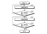
- FIG. 23 is a flowchart of a control processing procedure for suppressing voids.
- the controller 200 operates as the irradiation control unit 201, and the laser device 110 is formed by irradiating the object W with the laser beam L in a predetermined procedure to form the molten pool 23W. It also controls controlled objects such as the galvano scanner 126 and the drive mechanism 140 (S21). This S21 is a step of forming the molten pool 23W.
- the controller 200 also operates as the detection control unit 202, and detects the temperature of the molten pool 23W at a predetermined timing, for example, at a fixed time interval.
- the controller 200 is controlled by the laser device 110, the galvano scanner 126, the drive mechanism 140, and the like so that the temperature of the molten pool 23W is maintained at a predetermined temperature or changes over time.
- the target (variable mechanism) may be feedback-controlled.
- the controller 200 operates as the determination unit 203, and determines whether or not a predetermined condition (first condition) is satisfied for the forming process of the molten pool 23W (S22).
- the determination unit 203 determines that the first condition is satisfied when, for example, the time equal to or higher than the first threshold temperature continues for the first threshold time or longer based on the time course of the temperature of the molten pool 23W. ..
- the molten pool 23W and the member 20 can be brought into a state where sufficient descent times ⁇ t1 and ⁇ t2 can be secured for the void V to escape.
- the process of forming the molten pool 23W in S21 is continued.
- the processing procedure is completed for the laser welding apparatus 100 of the first embodiment.
- the process shifts to S23.
- the controller 200 operates as an irradiation control unit 201, and a laser device is used to irradiate the object W with the laser beam L, for example, only the beam B2 to maintain the molten pool 23W in a molten state. It controls a controlled object such as the 110, the galvano scanner 126, and the drive mechanism 140 (S23).
- This S23 is a maintenance step of the molten pool 23W.
- the controller 200 also operates as the detection control unit 202, and detects the temperature of the molten pool 23W at a predetermined timing, for example, at a fixed time interval.
- the controller 200 is controlled by the laser device 110, the galvano scanner 126, the drive mechanism 140, and the like so that the temperature of the molten pool 23W is maintained at a predetermined temperature or changes over time.
- the target (variable mechanism) may be feedback-controlled.
- the controller 200 operates as the determination unit 203, and determines whether or not a predetermined condition (second condition) is satisfied for the maintenance process of the molten pool 23W (S24).
- the determination unit 203 determines that the second condition is satisfied when, for example, the time of the second threshold temperature or higher continues for the second threshold time or longer based on the time course of the temperature of the molten pool 23W. ..
- the laser welding devices 100 and 100A output the sensor 150 for detecting the temperature of the molten pool 23W and the output indicating the welding quality based on the detection result by the sensor 150.
- a unit 220 may be provided.
- the presence or absence of void V in the welded portion 23 can be inspected relatively easily in a non-destructive manner, and the control parameters of the laser welding devices 100 and 100A are based on the judgment result of the welding quality.
- the welding quality in laser welding from the next time onward can be improved.
- the controller 200 is a controlled object (variable mechanism) such as a laser device 110, a galvano scanner 126, and a drive mechanism 140 based on the detection result of the sensor 150 that detects the temperature of the molten pool 23W. ) May be controlled.
- a controlled object such as a laser device 110, a galvano scanner 126, and a drive mechanism 140 based on the detection result of the sensor 150 that detects the temperature of the molten pool 23W.
- the formation of the molten pool 23W and the maintenance in the molten state can be performed more accurately, so that the void V can be suppressed more reliably and the generation of the void V can be suppressed.
- Advantages such as reduction of wasteful energy consumption can be obtained.
- the laser welding device may include a plurality of laser devices (laser light sources) that output laser light of the same wavelength.
- laser devices laser light sources
- known wobbling, weaving, output modulation, or the like may be performed to adjust the surface area of the molten pool.
- the present invention can be used for a laser welding method and a laser welding apparatus.
- Diffraction grating 126 ... Galvano scanner (variable mechanism) 126a, 126b ... Mirror 127 ... Filter 128 ... Mirror 130 ... Optical fiber 140 ... Drive mechanism (variable mechanism) 150 ... Sensor 200 ... Controller (control unit) 201 ... Irradiation control unit (control unit) 202 ... Detection control unit 203 ... Judgment unit 204 ... Output control unit 205 ... Parameter change unit 210 ... Storage unit 220 ... Output unit A1 ... Area A2 ... Area B1 ... Beam (main beam, main power area) B1a ... Outer edge B2 ... Beam (secondary beam, secondary power region) B2a ... Outer edge B2b ...
Landscapes
- Physics & Mathematics (AREA)
- Optics & Photonics (AREA)
- Engineering & Computer Science (AREA)
- Plasma & Fusion (AREA)
- Mechanical Engineering (AREA)
- Laser Beam Processing (AREA)
Abstract
Description
[レーザ溶接装置の構成]
図1は、第1実施形態のレーザ溶接装置100の概略構成を示す図である。図1に示されるように、レーザ溶接装置100は、レーザ装置110と、光学ヘッド120と、光ファイバ130と、駆動機構140と、センサ150と、コントローラ200と、を備えている。
DOE125は、コリメートされたレーザ光を、複数のビームに分割する。図5~8は、それぞれ、対象物Wの表面Wa上に形成されたレーザ光Lのビームの一例を示す図である。なお、図5~8では、簡単のため、ビームB1が実線で示され、ビームB2が破線で示されている。なお、光学ヘッド120は、DOE125を交換することにより、種々の配置の複数のビームを含むレーザ光を出力することができる。DOE125は、ビームシェイパの一例である。
図9は、レーザ溶接方法の溶融池23Wを形成する工程(以下、形成工程と称する)における対象物Wの側面図である。なお、以下では、説明の便宜上、部材21の端部21aに対して照射されるレーザ光Lをレーザ光L1と記し、部材22の端部22aに対して照射されるレーザ光Lをレーザ光L2と記しているが、これらレーザ光L1,L2は、いずれも同じ光学ヘッド120から出射されている。
図12は、部材20を含む平角線10の斜視図である。部材20は、一例として、図12に示されるような平角線10の芯線(内部導体)である。平角線10は、部材20と、部材20の被覆30と、を有している。部材20は、導電性を有した金属材料で作られている。部材20の、延び方向に対して直交する断面の形状は、略四角形状である。被覆30は、絶縁性を有しており、例えば、エナメルや、合成樹脂材料等で作られる。被覆30は、エナメル層と、当該エナメル層を取り囲む押出樹脂層と、を有してもよい。レーザ溶接装置100は、このような平角線10の芯線としての部材20の、端部20a同士の溶接に適用される。この場合、二つの平角線10の延び方向の端部の近傍において、被覆30が除去される。そして、図2に示されるように、同じ方向(延び方向)を向く姿勢で隣接して配置された二つの部材20の端部20aが、レーザ溶接装置100によって溶接される。
図13は、溶接部23の例示的な側面図である。本実施形態では、図13に示されるように、溶接部23の下側半分RlのボイドVの数が溶接部23の上側半分RuのボイドVの数以下となるよう、レーザ光Lの照射条件、特にビームB2(副ビーム)の照射条件を設定する。ここで、仮想平面VPは、溶接部23の溶接時および固化時の鉛直方向における当該溶接部23の上端23aと当該鉛直方向における下端23bとの間の丁度中間位置を通り、溶接時および固化時の水平方向に広がった平面とする。上側半分Ruは、仮想平面VPよりも上側の部位であって、仮想平面VPに対して下側半分Rlとは反対側の部位とする。また、下側半分Rlは、溶接部23のうち、仮想平面VPよりも下側の部位であって、仮想平面VPに対して上側半分Ruとは反対側の部位とする。溶融池23Wにおいて、ボイドVは上方に移動する。よって、レーザ光L(ビームB2)の照射によって溶融池23Wの溶融状態が維持されると、下側半分Rlに生じたボイドVは上昇し、上側半分Ruあるいは溶融池23W外へ移動し、抜けられなかったボイドVが主として上側半分Ruに残存する。したがって、溶接部23において下側半分RlのボイドVの数が上側半分RuのボイドVの数以下となる状態が得られる。すなわち、溶接部23において下側半分RlのボイドVの数が上側半分RuのボイドVの数以下となっている状態は、ビームB2の照射によるボイドVの低減の効果が得られた状態であると言える。
[レーザ溶接装置の構成]
図14は、第2実施形態のレーザ溶接装置100Aの概略構成を示す図である。図14に示されるように、レーザ溶接装置100Aは、複数のレーザ装置111,112(110)を備えるとともに光学ヘッド120Aに設けられたセンサ150を備えている点が、上記第1実施形態と相違している。また、これらを備えることに伴い、光学ヘッド120Aが、コリメートレンズ121-2、フィルタ124,127、およびミラー128を有している点も、上記第1実施形態と相違している。
ここで、金属材料の光の吸収率について説明する。図15は、照射するレーザ光Lの波長に対する各金属材料の光の吸収率を示すグラフである。図15のグラフの横軸は波長であり、縦軸は吸収率である。図15には、アルミニウム(Al)、銅(Cu)、金(Au)、ニッケル(Ni)、銀(Ag)、タンタル(Ta)、およびチタン(Ti)について、波長と吸収率との関係が示されている。
図16は、本実施形態による溶接における溶融池23Wの温度およびレーザ装置111,112(110)からのレーザ光の出力の経時変化を示す図である。図16において、温度についての表記は、第1実施形態の図11と同じである。ただし、レーザ光の出力については、第一レーザ光(主ビーム)の出力の経時変化を実線で示し、第二レーザ光(副ビーム)の出力の経時変化を破線で示している。
発明者らの実験的な研究により、維持工程において照射されるレーザ光Lの溶融池23Wの表面におけるパワー密度[W/cm2]は、好適な範囲があることが判明した。

[レーザ溶接装置のブロック図および処理手順]
図21は、レーザ溶接装置100,100Aのブロック図である。レーザ溶接装置100,100Aは、例えば、コントローラ200と、記憶部210と、センサ150と、レーザ装置110と、ガルバノスキャナ126と、駆動機構140と、出力部220と、を備えている。
図22は、検査結果を出力する処理手順のフローチャートである。図22に示されるように、まず、コントローラ200は、照射制御部201として作動し、所定の手順で対象物Wに対してレーザ光Lを照射して当該対象物Wを溶接するよう、レーザ装置110、ガルバノスキャナ126、および駆動機構140を制御する(S11)。このS11において、照射制御部201は、上述したように、少なくとも一つのボイドVが溶融池23Wから排出されるのに要する降下時間Δt1,Δt2が生じるビームB1,B2のスペック、ならびに維持時間Δtkで、対象物Wにレーザ光Lを照射するよう、レーザ装置110、ガルバノスキャナ126、および駆動機構140のうち少なくとも一つの作動を制御する。レーザ装置110、ガルバノスキャナ126、および駆動機構140は、レーザ溶接装置100,100Aにおけるコントローラ200による被制御対象であるとともに、レーザ光Lの照射状態を変更することが可能な可変機構の一例である。照射制御部201およびコントローラ200は、制御部の一例である。
図23は、ボイドを抑制する制御の処理手順のフローチャートである。図23に示されるように、まず、コントローラ200は、照射制御部201として作動し、所定の手順で対象物Wに対してレーザ光Lを照射して溶融池23Wを形成するよう、レーザ装置110や、ガルバノスキャナ126、駆動機構140などの被制御対象を制御する(S21)。このS21は、溶融池23Wの形成工程である。このS21において、コントローラ200は、検出制御部202としても作動しており、所定のタイミングで、例えば、一定の時間間隔で、溶融池23Wの温度を検出している。
20…部材
20a…端部
20b…側面
21…部材(第一部材)
21a…端部(第一端部)
21b…側面
22…部材(第二部材)
22a…端部(第二端部)
22b…側面
23…溶接部
23W…溶融池
23a…上端
23b…下端
30…被覆
100,100A…レーザ溶接装置
110,111,112…レーザ装置(レーザ発振器、可変機構)
120,120A…光学ヘッド
121,121-1,121-2…コリメートレンズ
122…集光レンズ
123…ミラー
124…フィルタ
125…DOE
125a…回折格子
126…ガルバノスキャナ(可変機構)
126a,126b…ミラー
127…フィルタ
128…ミラー
130…光ファイバ
140…駆動機構(可変機構)
150…センサ
200…コントローラ(制御部)
201…照射制御部(制御部)
202…検出制御部
203…判定部
204…出力制御部
205…パラメータ変更部
210…記憶部
220…出力部
A1…領域
A2…領域
B1…ビーム(主ビーム、主パワー領域)
B1a…外縁
B2…ビーム(副ビーム、副パワー領域)
B2a…外縁
B2b…内縁
b2…ビーム
C…中心
C1…中心
C2…中心
g…隙間
L,L1,L2…レーザ光
Pd…パワー密度
Ru…上側半分
Rl…下側半分
t0,t1,t2,te1,ter,tk…時刻
T1,T2,Tr…温度
Tm…融点
V…ボイド
VP…仮想平面
W…対象物
Wa…表面
X…方向(第二方向)
Y…方向(第三方向)
Z…方向(第一方向)
δ…ずれ
Δt1,Δt2…降下時間
Δtk…維持時間
ΔT…温度差
Claims (28)
- 少なくとも一つの主ビームを含む主パワー領域と、当該主ビームよりもパワー密度が小さい少なくとも一つの副ビームを含む副パワー領域と、を含むレーザ光を対象物に照射して当該対象物を溶接するレーザ溶接方法であって、
前記対象物に前記レーザ光を照射することにより溶融池を形成する工程と、
前記溶融池を固化する工程と、
を有し、
前記副ビームは、前記溶融池内に形成されたボイドが、当該溶融池が固化する前に当該溶融池外へ抜けるように、前記対象物に照射される、レーザ溶接方法。 - 前記溶融池を形成する工程では、当該溶融池が固化されて形成された溶接部の下側半分におけるボイドの数が上側半分におけるボイドの数以下になるよう、前記レーザ光を照射する請求項1に記載のレーザ溶接方法。
- 前記主パワー領域は、前記副パワー領域の外縁の内側に位置している、請求項1に記載のレーザ溶接方法。
- 前記副パワー領域は、前記少なくとも一つの副ビームとして複数の副ビームを含み、
前記主ビームは、前記複数の副ビームに取り囲まれている、請求項1に記載のレーザ溶接方法。 - 前記副パワー領域は、前記少なくとも一つの副ビームとして、前記主パワー領域を取り囲む一つの副ビームを含む、請求項1に記載のレーザ溶接方法。
- 前記溶融池を形成する工程の後に、前記溶融池に前記レーザ光を照射することにより当該溶融池を溶融状態で一時的に維持する工程を有した、請求項1~5のうちいずれか一つに記載のレーザ溶接方法。
- 前記溶融池を溶融状態で一時的に維持する工程では、前記溶融池を形成する工程に比べて、前記レーザ光のパワーを低くする、請求項6に記載のレーザ溶接方法。
- 前記溶融池を溶融状態で一時的に維持する工程では、前記溶融池を形成する工程に比べて、前記主ビームのパワーを低くする、請求項6または7に記載のレーザ溶接方法。
- 前記溶融池を溶融状態で一時的に維持する工程で前記レーザ光の照射によって前記溶融池の表面に生じる凹みは、前記溶融池を形成する工程で前記レーザ光の照射によって前記溶融池の表面に生じる凹みよりも浅い、請求項6~8のうちいずれか一つに記載のレーザ溶接方法。
- 前記溶融池を溶融状態で一時的に維持する工程では、前記レーザ光の前記溶融池の表面におけるパワー密度が、107[W/cm2]以下である、請求項6~9のうちいずれか一つに記載のレーザ溶接方法。
- 前記溶融池を溶融状態で一時的に維持する工程では、前記レーザ光の前記溶融池の表面におけるパワー密度が、106[W/cm2]以下である、請求項10に記載のレーザ溶接方法。
- 前記溶融池を形成する工程では、前記主ビームを照射し、
前記溶融池を溶融状態で一時的に維持する工程では、前記主ビームの照射を停止する、請求項6~11のうちいずれか一つに記載のレーザ溶接方法。 - 前記溶融池を形成する工程から前記溶融池を溶融状態で一時的に維持する工程にかけて、前記主ビームの照射時間が前記副ビームの照射時間よりも短い、請求項6~12のうちいずれか一つに記載のレーザ溶接方法。
- 前記主ビームの波長と前記副ビームの波長とが同じである、請求項1~13のうちいずれか一つに記載のレーザ溶接方法。
- 前記主ビームの波長と前記副ビームの波長とが異なる、請求項1~14のうちいずれか一つに記載のレーザ溶接方法。
- 前記主ビームの波長は800[nm]以上かつ1200[nm]以下であり、前記副ビームの波長は550[nm]以下である、請求項15に記載のレーザ溶接方法。
- 前記主パワー領域および前記副パワー領域のうち少なくとも一方に含まれる複数のビームをビームシェイパによって形成する、請求項1~16のうちいずれか一つに記載のレーザ溶接方法。
- 前記レーザ光を前記対象物に対して照射しながら掃引する、請求項1~17のうちいずれか一つに記載のレーザ溶接方法。
- 前記副パワー領域の少なくとも一部は、前記主パワー領域に対して、前記対象物に対する前記レーザ光の掃引方向の後方に位置する、請求項18に記載のレーザ溶接方法。
- 前記レーザ光を直線状に掃引する、請求項18または19に記載のレーザ溶接方法。
- 前記溶融池を溶融状態で一時的に維持する工程では、前記レーザ光を定点に照射する、請求項18~20のうちいずれか一つに記載のレーザ溶接方法。
- 前記溶融池を溶融状態で一時的に維持する工程では、前記レーザ光の照射方向に見た場合に前記溶融池の中心周りに曲がった経路で前記レーザ光を掃引する、請求項18~21のうちいずれか一つに記載のレーザ溶接方法。
- 前記対象物は、銅系金属材料、アルミニウム系金属材料、ニッケル系金属材料、鉄系金属材料、およびチタン系金属材料のうちのいずれか一つで作られた、請求項1~22のうちいずれか一つに記載のレーザ溶接方法。
- 前記溶融池は、金属材料で作られた第一部材の第一方向の第一端部と、前記第一部材に対して前記第一方向と交差した第二方向に隣接し金属材料で作られた第二部材の前記第一方向の第二端部であって前記第一端部の当該第二端部からの前記第一方向に沿った距離が0以上となるように配置された第二端部と、の間で掛け渡されるように形成される、請求項1~23のうちいずれか一つに記載のレーザ溶接方法。
- 前記対象物を構成する部材は、平角線の導体である、請求項24に記載のレーザ溶接方法。
- レーザ発振器と、
前記レーザ発振器から出射されたレーザ光を対象物に照射する光学ヘッドと、
を備え、
前記レーザ光は、少なくとも一つの主ビームと、当該主ビームよりもパワー密度が小さい少なくとも一つの副ビームと、を含み、前記対象物に溶融池を形成するように照射され、
前記副ビームは、前記溶融池内に形成されたボイドが、当該溶融池が固化する前に当該溶融池外へ抜けるように、前記対象物に照射される、レーザ溶接装置。 - 前記溶融池の温度を検出するセンサと、
前記センサの検出結果に基づいて溶接品質を示す情報を出力する出力部と、
を備えた、請求項26に記載のレーザ溶接装置。 - 前記溶融池の温度を検出するセンサと、
前記レーザ光の照射状態を変更可能な可変機構と、
前記センサの検出結果に基づいて前記可変機構の作動を制御する制御部と、
を備えた、請求項26または27に記載のレーザ溶接装置。
Priority Applications (4)
| Application Number | Priority Date | Filing Date | Title |
|---|---|---|---|
| KR1020237012464A KR20230066105A (ko) | 2020-10-20 | 2021-10-18 | 레이저 용접 방법 및 레이저 용접 장치 |
| JP2022557524A JPWO2022085632A1 (ja) | 2020-10-20 | 2021-10-18 | |
| CN202180069667.5A CN116323069A (zh) | 2020-10-20 | 2021-10-18 | 激光焊接方法以及激光焊接装置 |
| US18/301,459 US20230311243A1 (en) | 2020-10-20 | 2023-04-17 | Laser welding method and laser welding device |
Applications Claiming Priority (2)
| Application Number | Priority Date | Filing Date | Title |
|---|---|---|---|
| JP2020176331 | 2020-10-20 | ||
| JP2020-176331 | 2020-10-20 |
Related Child Applications (1)
| Application Number | Title | Priority Date | Filing Date |
|---|---|---|---|
| US18/301,459 Continuation US20230311243A1 (en) | 2020-10-20 | 2023-04-17 | Laser welding method and laser welding device |
Publications (1)
| Publication Number | Publication Date |
|---|---|
| WO2022085632A1 true WO2022085632A1 (ja) | 2022-04-28 |
Family
ID=81290858
Family Applications (1)
| Application Number | Title | Priority Date | Filing Date |
|---|---|---|---|
| PCT/JP2021/038448 Ceased WO2022085632A1 (ja) | 2020-10-20 | 2021-10-18 | レーザ溶接方法およびレーザ溶接装置 |
Country Status (6)
| Country | Link |
|---|---|
| US (1) | US20230311243A1 (ja) |
| JP (1) | JPWO2022085632A1 (ja) |
| KR (1) | KR20230066105A (ja) |
| CN (1) | CN116323069A (ja) |
| TW (1) | TW202222463A (ja) |
| WO (1) | WO2022085632A1 (ja) |
Cited By (4)
| Publication number | Priority date | Publication date | Assignee | Title |
|---|---|---|---|---|
| JP2023180660A (ja) * | 2022-06-10 | 2023-12-21 | パナソニックIpマネジメント株式会社 | レーザ加工装置 |
| JP2024052263A (ja) * | 2022-09-30 | 2024-04-11 | 古河電気工業株式会社 | レーザ溶接方法およびレーザ溶接装置 |
| JP2024052264A (ja) * | 2022-09-30 | 2024-04-11 | 古河電気工業株式会社 | レーザ溶接方法およびレーザ溶接装置 |
| JP2024157413A (ja) * | 2023-04-25 | 2024-11-07 | 本田技研工業株式会社 | レーザ溶接方法およびレーザ溶接システム |
Families Citing this family (5)
| Publication number | Priority date | Publication date | Assignee | Title |
|---|---|---|---|---|
| JP7225166B2 (ja) * | 2020-07-22 | 2023-02-20 | 矢崎総業株式会社 | 電線の製造方法および電線製造装置 |
| DE102023122749A1 (de) * | 2023-08-24 | 2025-02-27 | TRUMPF Laser SE | Verfahren und Vorrichtung zum Laserschweißen von mindestens zwei Leiterstücken, sowie Anordnung von mindestens zwei miteinander stoffschlüssig verbundenen Leiterstücken |
| DE102023122748A1 (de) * | 2023-08-24 | 2025-02-27 | TRUMPF Laser SE | Verfahren und Vorrichtung zum Laserschweißen von mindestens zwei Leiterstücken, sowie Anordnung von mindestens zwei miteinander stoffschlüssig verbundenen Leiterstücken |
| CN118060715A (zh) * | 2024-03-27 | 2024-05-24 | 湖北亿纬动力有限公司 | 一种电池外壳的焊接工艺及焊接设备 |
| WO2026027464A1 (en) | 2024-07-31 | 2026-02-05 | Atop S.P.A. | Laser welding station and method for welding together elements of metal manufactured products |
Citations (5)
| Publication number | Priority date | Publication date | Assignee | Title |
|---|---|---|---|---|
| JP2000000683A (ja) * | 1998-06-12 | 2000-01-07 | Advanced Materials Processing Inst Kinki Japan | レーザ溶接方法 |
| JP2000218383A (ja) * | 1999-01-28 | 2000-08-08 | Suzuki Motor Corp | レーザ溶接における溶接温度制御方法 |
| JP2003340582A (ja) * | 2002-05-23 | 2003-12-02 | Mitsubishi Heavy Ind Ltd | レーザ溶接装置およびレーザ溶接方法 |
| JP2015205327A (ja) * | 2014-04-22 | 2015-11-19 | パナソニックIpマネジメント株式会社 | レーザ溶接方法及び装置 |
| WO2019203367A1 (ja) * | 2018-04-20 | 2019-10-24 | 古河電気工業株式会社 | 溶接方法および溶接装置 |
Family Cites Families (5)
| Publication number | Priority date | Publication date | Assignee | Title |
|---|---|---|---|---|
| JP5191648B2 (ja) * | 2006-11-07 | 2013-05-08 | 東京特殊電線株式会社 | レーザ溶接装置及びレーザ溶接方法 |
| CN105834587B (zh) * | 2016-05-28 | 2017-10-13 | 北京工业大学 | 一种焊剂辅助的激光焊接方法 |
| CN110402179A (zh) * | 2017-03-03 | 2019-11-01 | 古河电气工业株式会社 | 焊接方法及焊接装置 |
| JP6674588B1 (ja) | 2019-02-22 | 2020-04-01 | 株式会社東芝 | 銅を含む部材の溶接方法、および回転電機の製造方法 |
| CN110170742B (zh) * | 2019-06-25 | 2020-07-31 | 华中科技大学 | 一种铝合金中厚板激光焊接装置及方法 |
-
2021
- 2021-10-18 KR KR1020237012464A patent/KR20230066105A/ko not_active Ceased
- 2021-10-18 JP JP2022557524A patent/JPWO2022085632A1/ja active Pending
- 2021-10-18 WO PCT/JP2021/038448 patent/WO2022085632A1/ja not_active Ceased
- 2021-10-18 CN CN202180069667.5A patent/CN116323069A/zh active Pending
- 2021-10-19 TW TW110138709A patent/TW202222463A/zh unknown
-
2023
- 2023-04-17 US US18/301,459 patent/US20230311243A1/en active Pending
Patent Citations (5)
| Publication number | Priority date | Publication date | Assignee | Title |
|---|---|---|---|---|
| JP2000000683A (ja) * | 1998-06-12 | 2000-01-07 | Advanced Materials Processing Inst Kinki Japan | レーザ溶接方法 |
| JP2000218383A (ja) * | 1999-01-28 | 2000-08-08 | Suzuki Motor Corp | レーザ溶接における溶接温度制御方法 |
| JP2003340582A (ja) * | 2002-05-23 | 2003-12-02 | Mitsubishi Heavy Ind Ltd | レーザ溶接装置およびレーザ溶接方法 |
| JP2015205327A (ja) * | 2014-04-22 | 2015-11-19 | パナソニックIpマネジメント株式会社 | レーザ溶接方法及び装置 |
| WO2019203367A1 (ja) * | 2018-04-20 | 2019-10-24 | 古河電気工業株式会社 | 溶接方法および溶接装置 |
Cited By (4)
| Publication number | Priority date | Publication date | Assignee | Title |
|---|---|---|---|---|
| JP2023180660A (ja) * | 2022-06-10 | 2023-12-21 | パナソニックIpマネジメント株式会社 | レーザ加工装置 |
| JP2024052263A (ja) * | 2022-09-30 | 2024-04-11 | 古河電気工業株式会社 | レーザ溶接方法およびレーザ溶接装置 |
| JP2024052264A (ja) * | 2022-09-30 | 2024-04-11 | 古河電気工業株式会社 | レーザ溶接方法およびレーザ溶接装置 |
| JP2024157413A (ja) * | 2023-04-25 | 2024-11-07 | 本田技研工業株式会社 | レーザ溶接方法およびレーザ溶接システム |
Also Published As
| Publication number | Publication date |
|---|---|
| TW202222463A (zh) | 2022-06-16 |
| KR20230066105A (ko) | 2023-05-12 |
| JPWO2022085632A1 (ja) | 2022-04-28 |
| CN116323069A (zh) | 2023-06-23 |
| US20230311243A1 (en) | 2023-10-05 |
Similar Documents
| Publication | Publication Date | Title |
|---|---|---|
| KR20230066105A (ko) | 레이저 용접 방법 및 레이저 용접 장치 | |
| JP7733087B2 (ja) | レーザ溶接方法 | |
| JP7326617B2 (ja) | バスバーおよびバスバーの製造方法 | |
| JP7336035B2 (ja) | 溶接方法および溶接装置 | |
| JP7547453B2 (ja) | 溶接方法およびレーザ溶接システム | |
| CN110116499A (zh) | 用于三维结构的增材制造的设备和方法 | |
| JP7687883B2 (ja) | 半導体装置および溶接方法 | |
| JP7269443B2 (ja) | 溶接方法および溶接装置 | |
| JP7585464B2 (ja) | レーザ溶接方法およびレーザ溶接装置 | |
| JP2025100655A (ja) | レーザ溶接方法およびレーザ溶接装置 | |
| JP7857379B2 (ja) | 溶接方法、金属積層体、電気部品、および電気製品 | |
| JP7608079B2 (ja) | 溶接方法および溶接装置 | |
| WO2023085336A1 (ja) | 溶接方法、溶接装置、および金属積層体 | |
| JP2024052264A (ja) | レーザ溶接方法およびレーザ溶接装置 | |
| JP5659705B2 (ja) | エンジンの冷却構造およびエンジンの冷却構造の製造方法 | |
| JP2024052263A (ja) | レーザ溶接方法およびレーザ溶接装置 | |
| JP2024076250A (ja) | レーザ溶接方法およびレーザ溶接装置 | |
| JP2024072511A (ja) | 積層造形方法および積層造形装置 | |
| CN120239638A (zh) | 激光焊接方法 | |
| JP2024127301A (ja) | 電線接続端子の製造方法、電線接続端子、および端子付き電線 | |
| WO2024111593A1 (ja) | 接合方法およびレーザ加工装置 | |
| JP2023053696A (ja) | 金属箔のレーザ切断方法 | |
| JP2024143700A (ja) | 溶接方法および溶接装置 |
Legal Events
| Date | Code | Title | Description |
|---|---|---|---|
| 121 | Ep: the epo has been informed by wipo that ep was designated in this application |
Ref document number: 21882773 Country of ref document: EP Kind code of ref document: A1 |
|
| ENP | Entry into the national phase |
Ref document number: 20237012464 Country of ref document: KR Kind code of ref document: A |
|
| ENP | Entry into the national phase |
Ref document number: 2022557524 Country of ref document: JP Kind code of ref document: A |
|
| NENP | Non-entry into the national phase |
Ref country code: DE |
|
| 122 | Ep: pct application non-entry in european phase |
Ref document number: 21882773 Country of ref document: EP Kind code of ref document: A1 |