WO2022085618A1 - フィルタユニット - Google Patents
フィルタユニット Download PDFInfo
- Publication number
- WO2022085618A1 WO2022085618A1 PCT/JP2021/038386 JP2021038386W WO2022085618A1 WO 2022085618 A1 WO2022085618 A1 WO 2022085618A1 JP 2021038386 W JP2021038386 W JP 2021038386W WO 2022085618 A1 WO2022085618 A1 WO 2022085618A1
- Authority
- WO
- WIPO (PCT)
- Prior art keywords
- tube
- filter unit
- joint
- cap
- opening
- Prior art date
- Legal status (The legal status is an assumption and is not a legal conclusion. Google has not performed a legal analysis and makes no representation as to the accuracy of the status listed.)
- Ceased
Links
Images






Classifications
-
- B—PERFORMING OPERATIONS; TRANSPORTING
- B01—PHYSICAL OR CHEMICAL PROCESSES OR APPARATUS IN GENERAL
- B01D—SEPARATION
- B01D53/00—Separation of gases or vapours; Recovering vapours of volatile solvents from gases; Chemical or biological purification of waste gases, e.g. engine exhaust gases, smoke, fumes, flue gases, aerosols
- B01D53/02—Separation of gases or vapours; Recovering vapours of volatile solvents from gases; Chemical or biological purification of waste gases, e.g. engine exhaust gases, smoke, fumes, flue gases, aerosols by adsorption, e.g. preparative gas chromatography
- B01D53/04—Separation of gases or vapours; Recovering vapours of volatile solvents from gases; Chemical or biological purification of waste gases, e.g. engine exhaust gases, smoke, fumes, flue gases, aerosols by adsorption, e.g. preparative gas chromatography with stationary adsorbents
- B01D53/0407—Constructional details of adsorbing systems
- B01D53/0415—Beds in cartridges
-
- B—PERFORMING OPERATIONS; TRANSPORTING
- B01—PHYSICAL OR CHEMICAL PROCESSES OR APPARATUS IN GENERAL
- B01D—SEPARATION
- B01D46/00—Filters or filtering processes specially modified for separating dispersed particles from gases or vapours
- B01D46/0002—Casings; Housings; Frame constructions
- B01D46/001—Means for connecting filter housings to supports
-
- B—PERFORMING OPERATIONS; TRANSPORTING
- B01—PHYSICAL OR CHEMICAL PROCESSES OR APPARATUS IN GENERAL
- B01D—SEPARATION
- B01D46/00—Filters or filtering processes specially modified for separating dispersed particles from gases or vapours
- B01D46/0002—Casings; Housings; Frame constructions
- B01D46/0005—Mounting of filtering elements within casings, housings or frames
-
- B—PERFORMING OPERATIONS; TRANSPORTING
- B01—PHYSICAL OR CHEMICAL PROCESSES OR APPARATUS IN GENERAL
- B01D—SEPARATION
- B01D46/00—Filters or filtering processes specially modified for separating dispersed particles from gases or vapours
- B01D46/0002—Casings; Housings; Frame constructions
- B01D46/0017—Filter elements installed in a branch of a pipe, e.g. with an y-shaped tubular housing
-
- B—PERFORMING OPERATIONS; TRANSPORTING
- B01—PHYSICAL OR CHEMICAL PROCESSES OR APPARATUS IN GENERAL
- B01D—SEPARATION
- B01D53/00—Separation of gases or vapours; Recovering vapours of volatile solvents from gases; Chemical or biological purification of waste gases, e.g. engine exhaust gases, smoke, fumes, flue gases, aerosols
- B01D53/02—Separation of gases or vapours; Recovering vapours of volatile solvents from gases; Chemical or biological purification of waste gases, e.g. engine exhaust gases, smoke, fumes, flue gases, aerosols by adsorption, e.g. preparative gas chromatography
- B01D53/04—Separation of gases or vapours; Recovering vapours of volatile solvents from gases; Chemical or biological purification of waste gases, e.g. engine exhaust gases, smoke, fumes, flue gases, aerosols by adsorption, e.g. preparative gas chromatography with stationary adsorbents
- B01D53/0407—Constructional details of adsorbing systems
- B01D53/0446—Means for feeding or distributing gases
-
- F—MECHANICAL ENGINEERING; LIGHTING; HEATING; WEAPONS; BLASTING
- F16—ENGINEERING ELEMENTS AND UNITS; GENERAL MEASURES FOR PRODUCING AND MAINTAINING EFFECTIVE FUNCTIONING OF MACHINES OR INSTALLATIONS; THERMAL INSULATION IN GENERAL
- F16L—PIPES; JOINTS OR FITTINGS FOR PIPES; SUPPORTS FOR PIPES, CABLES OR PROTECTIVE TUBING; MEANS FOR THERMAL INSULATION IN GENERAL
- F16L55/00—Devices or appurtenances for use in, or in connection with, pipes or pipe systems
- F16L55/24—Preventing accumulation of dirt or other matter in pipes, e.g. by traps, by strainers
-
- B—PERFORMING OPERATIONS; TRANSPORTING
- B01—PHYSICAL OR CHEMICAL PROCESSES OR APPARATUS IN GENERAL
- B01D—SEPARATION
- B01D2253/00—Adsorbents used in seperation treatment of gases and vapours
- B01D2253/10—Inorganic adsorbents
- B01D2253/102—Carbon
-
- B—PERFORMING OPERATIONS; TRANSPORTING
- B01—PHYSICAL OR CHEMICAL PROCESSES OR APPARATUS IN GENERAL
- B01D—SEPARATION
- B01D2253/00—Adsorbents used in seperation treatment of gases and vapours
- B01D2253/10—Inorganic adsorbents
- B01D2253/104—Alumina
-
- B—PERFORMING OPERATIONS; TRANSPORTING
- B01—PHYSICAL OR CHEMICAL PROCESSES OR APPARATUS IN GENERAL
- B01D—SEPARATION
- B01D2253/00—Adsorbents used in seperation treatment of gases and vapours
- B01D2253/10—Inorganic adsorbents
- B01D2253/106—Silica or silicates
- B01D2253/108—Zeolites
-
- B—PERFORMING OPERATIONS; TRANSPORTING
- B01—PHYSICAL OR CHEMICAL PROCESSES OR APPARATUS IN GENERAL
- B01D—SEPARATION
- B01D2253/00—Adsorbents used in seperation treatment of gases and vapours
- B01D2253/25—Coated, impregnated or composite adsorbents
-
- B—PERFORMING OPERATIONS; TRANSPORTING
- B01—PHYSICAL OR CHEMICAL PROCESSES OR APPARATUS IN GENERAL
- B01D—SEPARATION
- B01D2257/00—Components to be removed
- B01D2257/20—Halogens or halogen compounds
- B01D2257/204—Inorganic halogen compounds
-
- B—PERFORMING OPERATIONS; TRANSPORTING
- B01—PHYSICAL OR CHEMICAL PROCESSES OR APPARATUS IN GENERAL
- B01D—SEPARATION
- B01D2257/00—Components to be removed
- B01D2257/30—Sulfur compounds
- B01D2257/302—Sulfur oxides
-
- B—PERFORMING OPERATIONS; TRANSPORTING
- B01—PHYSICAL OR CHEMICAL PROCESSES OR APPARATUS IN GENERAL
- B01D—SEPARATION
- B01D2257/00—Components to be removed
- B01D2257/30—Sulfur compounds
- B01D2257/304—Hydrogen sulfide
-
- B—PERFORMING OPERATIONS; TRANSPORTING
- B01—PHYSICAL OR CHEMICAL PROCESSES OR APPARATUS IN GENERAL
- B01D—SEPARATION
- B01D2257/00—Components to be removed
- B01D2257/40—Nitrogen compounds
- B01D2257/404—Nitrogen oxides other than dinitrogen oxide
-
- B—PERFORMING OPERATIONS; TRANSPORTING
- B01—PHYSICAL OR CHEMICAL PROCESSES OR APPARATUS IN GENERAL
- B01D—SEPARATION
- B01D2258/00—Sources of waste gases
- B01D2258/06—Polluted air
Definitions
- the present invention relates to a filter unit.
- Patent Document 1 discloses a reactor for removing hydrogen chloride gas.
- a hydrogen chloride gas absorber is housed in a cylindrical body.
- the gas to be processed is supplied into the cylindrical body from one end of the cylindrical body, and the treated gas is discharged to the outside from the other end of the cylindrical body (see Patent Document 1).
- Patent Document 1 does not disclose a means for solving such a problem.
- the present invention has been made to solve such a problem, and an object of the present invention is to provide a filter unit that can be arranged relatively easily even if there are restrictions on an arrangement space or the like. ..
- a filter unit includes a tube, a chemical filter, a first joint, and a second joint.
- the tube includes a first end and a second end and is flexible.
- the chemical filter is housed in a tube.
- the first fitting is connected to the first end of the tube.
- the second fitting is connected to the second end of the tube.
- the first joint is configured to be directly or indirectly connected to a device that discharges compressed air.
- the tube is flexible and joints are connected to each of both ends of the tube. Therefore, according to this filter unit, the tube is easily deformed, and the connection between the tube and the device for discharging compressed air is easy, so that it is relatively easy even if the arrangement space is restricted.
- a filter unit can be placed in.
- each of the first and second joints may be a one-touch joint.
- the device for discharging compressed air and the like can be more easily connected to the tube.
- an opening is formed in each of the first and second ends, the filter unit further includes a cap attached to each opening, and each cap has a tip inside the opening.
- a mesh portion including a tubular portion to be inserted into a tubular portion, a flange portion formed at the rear end portion of the tubular portion and in contact with the edge of the opening, and a mesh portion attached to the flange portion and covering the opening. May include a mesh and an air filter filter medium.
- a cap including a mesh part is connected to the opening of the tube. Therefore, according to this filter unit, the chemical filter can be held in the tube without blocking the passage of the compressed air.
- the tubular portion may be formed with a taper that expands outward in the radial direction of the tubular portion as it approaches the rear end portion.
- the cap Since individual differences may occur in the tube, if the tubular part has a completely straight shape, the cap may not be properly connected to the tube depending on the inner diameter of the tube.
- the cap since the cap is formed with a taper, the taper comes into contact with the inner peripheral surface of the tube even if the inner diameter of the tube is slightly different due to individual differences. Therefore, according to this filter unit, the cap can be properly connected to the tube even if there are individual differences in the tube.
- the length from the tip portion to the rear end portion may be shorter than the length from the seal portion between the first joint and the tube to the rear end portion.
- the seal between the joint and the tube may be affected depending on the material and diameter of the cap.
- the length from the tip portion to the rear end portion is shorter than the length from the seal portion between the first joint and the tube to the rear end portion. Therefore, according to this filter unit, since the tip end portion of the cap does not reach the sealing portion between the joint and the tube, the sealing property between the joint and the tube can be sufficiently maintained.
- the length of the flange portion may be shorter than the length of the tapered portion of the tubular portion in the length direction of the tube.
- the length of the flange portion in the length direction of the tube becomes long, the connection force between the joint and the tube and the sealing property become weak.
- the length of the flange portion is shorter than the length of the tapered portion of the tubular portion in the length direction of the tube. Therefore, according to this filter unit, the connection force and the sealing property between the joint and the tube can be sufficiently maintained.
- the tube may be a pressure resistant tube.
- the inventors of the present application have compared to the case where the contamination gas is removed under atmospheric pressure by pressurizing the atmospheric pressure air or further pressurizing the compressed air and discharging it to the filter unit 10. It was confirmed that the gas could be removed efficiently.
- this filter unit since the tube is a pressure-resistant tube, it is possible to remove the contamination gas contained in the pressurized atmospheric pressure air or the pressurized compressed air. Therefore, the contamination gas can be efficiently removed.
- an opening is formed in each of the first and second ends, and a cap to be attached to each opening is further provided.
- the tip is inserted inside the opening.
- the tubular portion includes a tubular portion and a flange portion formed at the rear end portion of the tubular portion and in contact with the edge of the opening, and the tubular portion has an outer diameter between the front end portion and the rear end portion. It may be constant.
- the cap can be easily manufactured.
- the cap has a mesh portion formed integrally with at least one of a cylindrical portion and a flange portion so as to cover the opening.
- the mesh part is hard to come off.
- a filter unit includes a plurality of tubes, a chemical filter, a first joint, and a second joint.
- Each of the plurality of tubes includes a first end and a second end and is flexible.
- the chemical filter is housed in each of a plurality of tubes.
- the first fitting aggregates the first ends of each of the plurality of tubes.
- the second fitting aggregates the second ends of each of the plurality of tubes.
- the first joint is configured to be directly or indirectly connected to a device that discharges compressed air.
- the chemical filter is dispersed in a plurality of tubes. Therefore, when the amount of the chemical filter is the same, the thickness of each tube can be made thinner than when there is only one tube. As a result, according to this filter unit, the filter unit can be bent more easily and thinner.
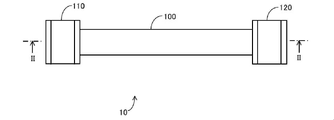
- FIG. It is a figure which shows the schematic structure of the filter unit of Embodiment 1.
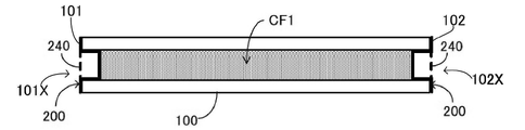
- FIG. It is a figure which shows typically the part which omitted the joint in the II-II cross section of FIG.
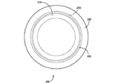
- FIG. It is a perspective view of a cap. It is a figure which shows the cap from the tip side. It is a side view of a cap. It is a figure which shows typically the periphery of the joint in the II-II cross section of FIG.
- It is a figure which shows typically the 2nd end part of the tube in the filter unit of Embodiment 2 and the periphery thereof.
- It is a side view of the cap of FIG. It is a front view of the cap of FIG.
- FIG. 1 is a diagram showing a schematic configuration of a filter unit 10 according to the present embodiment.
- the filter unit 10 is connected to, for example, an external device of the filter unit 10 and is configured to remove the contamination gas contained in the compressed air discharged by the device.
- the contamination gas include hydrogen sulfide, SOx, NOx, hydrogen chloride, hydrogen fluoride, acetic acid, silicic acid, nitric acid, sulfuric acid, ammonia, amine-based substances, chlorine, ozone, hydrogen peroxide, and hydrocarbons and fatty acids.
- Examples include organic substances such as silanol and siloxane.
- the filter unit 10 includes a tube 100, a first joint 110, and a second joint 120.
- the tube 100 is a flexible tubular member.
- the tube 100 is made of, for example, urethane, fluorine, polyolefin, nylon, or a laminate thereof. That is, the tube 100 is made of, for example, a thermoplastic resin. Since the tube 100 is made of a flexible member, it can be easily bent.
- the thermoplastic resin constituting the tube 100 is preferably a material having pressure resistance.
- the tube 100 is preferably a pressure resistant tube.
- the inventors of the present application have compared to the case where the contamination gas is removed under atmospheric pressure by pressurizing the atmospheric pressure air or further pressurizing the compressed air and discharging it to the filter unit 10. It has been found that the gas can be efficiently removed and the life of the tube 100 is extended.
- the maximum pressure of the pressurized compressed air is, for example, 0.7 MPa.
- the thermoplastic resin having pressure resistance is, for example, a special thermoplastic elastomer, urethane, fluorine, polyolefin, or nylon.
- the first joint 110 is connected to one end of the tube 100 in the length direction
- the second joint 120 is connected to the other end of the tube 100 in the length direction.
- one end of the tube 100 in the length direction is referred to as a first end 101 (see FIG. 2)
- the other end is referred to as a second end 102 (see FIG. 2).
- a pipe such as a tube 100 can be connected from both directions.
- Each of the first joint 110 and the second joint 120 is a so-called one-touch joint. Therefore, a pipe such as a tube 100 can be easily connected to each of the first joint 110 and the second joint 120 from both directions.
- a device for discharging compressed air is directly or indirectly connected to one of the first joint 110 and the second joint 120.
- the device include an air compressor, an N 2 gas generator, a gas cylinder, and a pump such as a vacuum pump and a compression pump.
- a pump such as a vacuum pump and a compression pump.
- a pipe such as a tube is connected to the other of the first joint 110 and the second joint 120, and the compressed air discharged by the pipe is supplied to the object.
- the object include a vacuum dryer in a pharmaceutical factory, an exhibition case installed in a museum, a household fuel cell, a computer installed in a data center, a control panel, a distribution board, a distribution board, and an operation panel.
- the objects include, for example, computers, control panels, distribution boards, distribution boards and operation panels installed in chemical factories, paper mills, water purification / sewage treatment plants, geothermal power plants, thermal power plants and hot spring areas. Can be mentioned.
- FIG. 2 is a diagram schematically showing a portion of the II-II cross section of FIG. 1 in which the first joint 110 and the second joint 120 are omitted.
- the filter unit 10 (see FIG. 1) further includes a chemical filter CF1 and a plurality (two) caps 200.
- the chemical filter CF1 is made of a material that can remove the contamination gas contained in the compressed air.
- Examples of the chemical filter CF1 include activated carbon, ion exchange resin, activated alumina impregnated with an oxidizing agent, zeolite, silica gel, mesoporous silica, molecular sieve, metal catalyst, sintered metal and photocatalyst.
- the chemical filter CF1 is filled inside the tube 100. Therefore, the contamination gas contained in the compressed air passing through the tube 100 is removed.
- a cap 200 including a mesh portion 240 is attached to each of both ends of the tube 100 in the length direction.
- the mesh portion 240 may include, for example, a mesh and an air filter filter medium, or may contain only a mesh.
- the opening size of the mesh portion 240 is such that elements constituting the chemical filter CF1, for example, activated carbon, do not flow out to the outside of the cap 200.
- FIG. 3 is a perspective view of the cap 200.
- FIG. 4 is a view showing the cap 200 from the tip side. In FIG. 4, the mesh portion 240 is omitted.
- FIG. 5 is a side view of the cap 200.
- the cap 200 includes a tubular portion 210, a flange portion 230, and a mesh portion 240.
- the tubular portion 210 has a circular shape in a plan view.
- the tip 210A (see FIG. 5) of the tubular portion 210 has an opening 101X (see FIG. 2) of the first end 101 in the length direction of the tube 100 and an opening 102X of the second end 102 (see FIG. 2). 2) is inserted.
- the flange portion 230 is formed at the rear end portion 210B of the tubular portion 210, and extends outward in the radial direction of the tubular portion 210. With the cap 200 attached to the tube 100, the front end surface of the flange 230 touches the edges of the openings 101X, 102X.
- the tubular portion 210 and the flange portion 230 are integrally formed of, for example, resin.
- a tapered portion 220 and a straight portion 250 are formed on the tubular portion 210.
- the taper 220 extends radially outward of the tubular portion 210 as it approaches the rear end portion 210B of the tubular portion 210.
- the straight portion 250 is formed between the taper 220 and the flange portion 230.
- the straight portion 250 has a constant outer diameter between the rear end portion 210B of the tubular portion 210 and the taper 220. The reason why the taper 220 is formed on the tubular portion 210 will be described below.
- the cap 200 may not be properly connected to the tube 100 depending on the inner diameter of the tube 100. For example, if the inner diameter of the tube 100 is larger than the outer diameter of the tubular portion 210, the cap 200 will not be properly connected to the tube 100.
- the taper 220 since the taper 220 is formed in the tubular portion 210, the taper 220 comes into contact with the inner peripheral surface of the tube 100 even if the inner diameter of the tube 100 is slightly different due to individual differences. Therefore, according to the filter unit 10, the cap 200 can be appropriately connected to the tube 100 even if there are individual differences in the tube 100.
- the length L2 of the flange portion 230 is shorter than the length L1 of the portion of the tubular portion 210 in which the taper 220 is formed. The reason for such a configuration will be described below.
- the tube 100 When the length L2 of the flange portion 230 in the length direction of the tube 100 becomes long, the tube 100 does not sufficiently penetrate into the depths of the first joint 110 and the second joint 120, so that the first joint 110 and the second joint 120 and the tube The connection force with 100 becomes weak.
- the length L2 of the flange portion 230 is shorter than the length L1 of the portion of the tubular portion 210 in which the taper 220 is formed in the length direction of the tube 100. Therefore, according to the filter unit 10, the tube 100 sufficiently penetrates deep into the first joint 110 and the second joint 120, so that the connection force between the first joint 110 and the second joint 120 and the tube 100 is sufficiently maintained. be able to.
- the mesh portion 240 is a mesh-like member.
- the mesh portion 240 is attached to the surface on the rear end side of the flange portion 230.
- the mesh portion 240 and the flange portion 230 may be bonded by, for example, an adhesive or by ultrasonic welding.
- the cap 200 including the mesh portion 240 is connected to the openings 101X and 102X of the tube 100. Therefore, according to the filter unit 10, the chemical filter CF1 can be held in the tube 100 without blocking the passage of the compressed air.
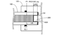
- FIG. 6 is a diagram schematically showing the periphery of the second joint 120 in the II-II cross section of FIG. 1.
- the cross-sectional structure of the second joint 120 is omitted except for the seal portion SL1.
- a cap 200 is attached to the second end 102 of the tube 100 in the longitudinal direction.
- a second joint 120 is attached to the tube 100 so as to cover the second end 102 and the cap 200.
- the tube 100 and the second joint 120 are sealed at the seal portion SL1.
- the seal portion SL1 is composed of, for example, a rubber ring.
- the length LA from the tip portion P2 (210A) of the cap 200 to the rear end portion P3 is shorter than the length LB from the seal portion SL1 (P1) to the rear end portion P3 of the cap 200. That is, the tip portion P2 (210A) of the cap 200 has not reached the position of the seal portion SL1.
- the sealing performance between the second joint 120 and the tube 100 may be affected depending on the material and outer diameter of the cap 200.
- the length LA from the tip portion P2 (210A) of the cap 200 to the rear end portion P3 is the sealing portion between the first joint 110 and the second joint 120 and the tube 100 (for example, the sealing portion SL1).
- the length from to the rear end P3 of the cap 200 is shorter than the length LB.
- the tip portion P2 (210A) of the cap 200 does not reach the sealing portion SL1 between the first joint 110 and the second joint 120 and the tube 100, the first joint 110 and the second joint The sealing property between the 120 and the tube 100 can be sufficiently maintained.
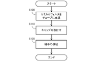
- FIG. 7 is a flowchart showing a manufacturing procedure of the filter unit 10. Each step shown in this flowchart is performed by an operator.
- the operator attaches the cap 200 to the second end 102 of the tube 100, and fills the tube 100 with the chemical filter CF1 (step S100).
- the operator attaches the cap 200 to the first end 101 of the tube 100 (step S110).
- the operator attaches the first joint 110 to the first end 101 of the tube 100 to which the cap 200 is attached to the first end 101 and the second end 102, and attaches the second joint 120 to the second end 102. (Step S120).
- the filter unit 10 is completed.
- the tube 100 has flexibility, the first joint 110 is connected to the first end portion 101 of the tube 100, and the second end portion 102 is connected to the first joint 110. Two fittings 120 are connected. Therefore, according to the filter unit 10, the tube 100 is easily deformed, and the device for discharging compressed air and the like can be easily connected to the tube 100. Therefore, even if there are restrictions on the arrangement space or the like, comparison is made.
- the filter unit 10 can be easily arranged.
- the filter unit 10X of the second embodiment is different from the filter unit 10 of the first embodiment in that the cap 200X is provided, and other configurations are the same as those of the first embodiment.
- the filter unit 10X of the second embodiment will be described focusing on a portion different from that of the first embodiment.
- FIG. 8 is a cross-sectional view of the second end 102 of the filter unit 10X and its periphery.
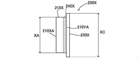
- FIG. 9 is a side view of the cap 200X.
- FIG. 10 is a front view of the cap 200X. In FIG. 8, the second joint 120 is not shown.
- the cap 200X has a tubular portion 210X, a flange portion 230X, and a mesh portion 240X.
- the tubular portion 210X has a circular shape in a plan view.
- the tip 210XA of the tubular portion 210X is inserted into the opening 101X (see FIG. 2) of the first end 101 in the length direction of the tube 100 and the opening 102X of the second end 102.
- the tubular portion 210X has a constant outer diameter XA (see FIG. 9) between the front end portion 210XA and the rear end portion 210YA. Therefore, the cap 200X can be easily manufactured.
- the outer diameter XA is smaller than the inner diameter XB of the tube 100 (see FIG. 8).
- a gap 300 is formed between the portion of the tubular portion 210X facing the inner peripheral surface of the tube 100 and the inner peripheral surface of the tube 100.
- the gap 300 is large enough to prevent elements constituting the chemical filter CF1, such as activated carbon, from flowing out of the tube 100. Since the first joint 110 is connected to the first end 101 of the tube 100 and the second joint 120 is connected to the second end 102, the cap 200X has the first joint 110 and the second joint 120. Retained by. Therefore, the cap 200X does not come off from the tube 100 during the use of the filter unit 10X.
- the flange portion 230X is formed at the rear end portion 210YA of the tubular portion 210X, and extends outward in the radial direction of the tubular portion 210X.
- the outer diameter XC of the flange portion 230X is slightly smaller than the outer diameter XD of the tube 100.
- the flange portion 230X is located inside the outer shell of the tube 100. Therefore, when the first joint 110 and the second joint 120 are connected to the tube 100, the first joint 110 and the second joint 120 and the cap 200X are less likely to interfere with each other.
- the tubular portion 210X and the flange portion 230X are integrally formed of, for example, resin.
- the resin is, for example, polypropylene or polyester.
- the material constituting the tubular portion 210X and the flange portion 230X is preferably transparent polypropylene.
- the welded state between the tubular portion 210X and the flange portion 230X and the mesh portion 240X can be easily confirmed.
- a mesh portion 240X is formed between the tip portion 210XA and the rear end portion 210YA of the tubular portion 210X. Therefore, the air permeability of the cap 200X is enhanced.
- the position where the mesh portion 240X is formed can be arbitrarily selected. From the viewpoint of accommodating a larger amount of the chemical filter CF1, the mesh portion 240X is preferably formed at a position close to the rear end portion 210YA of the tubular portion 210X.
- the mesh portion 240X is integrally formed with the tubular portion 210X and the flange portion 230X.
- the cap 200X is manufactured, for example, by injection molding the tubular portion 210X and the flange portion 230X with respect to the mesh portion 240X inserted into the mold for molding the tubular portion 210X and the flange portion 230X.
- the cap 200X may be manufactured by, for example, cutting or a molding method such as a 3D printer.
- the material constituting the mesh portion 240X is, for example, a resin. From the viewpoint of suppressing the generation of outgas, the material constituting the mesh portion 240 is preferably polyester.
- the opening size of the mesh portion 240X is such that elements constituting the chemical filter CF1, for example, activated carbon, do not flow out to the outside of the cap 200X.
- the cap 200X can be easily manufactured. Further, when the particle size of an element constituting the chemical filter CF1, for example, activated carbon or the like is large to some extent, even if a gap 300 is formed between the cap 200X and the tube 100, the activated carbon or the like is unlikely to flow out to the outside. Therefore, as in the present embodiment, a cap 200X that can be easily manufactured can be suitably adopted.
- the inventors of the present application manufactured the filter unit of the example and carried out the first test and the second test.
- the filter unit of the embodiment is the filter unit of the first embodiment, and the tube is a pressure resistant tube.
- the filter unit of the embodiment has an outer diameter of 12.7 mm and an inner diameter of 9.56 mm.
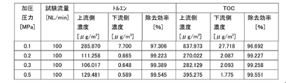
- the first test is a test for confirming the efficiency of removing contaminant gas when compressed air is pressurized.
- the second test is a test for confirming the life of the filter unit when compressed air is pressurized.
- the compressed air discharged from the device that discharges the compressed air is pressurized by a compressor, and the concentration of the contamination gas contained in the compressed air on the upstream side and the contamination gas contained in the compressed air on the downstream side.
- the concentration of was measured.
- the concentration of the contamination gas contained in the compressed air on the upstream side is the concentration of the contamination gas contained in the compressed air discharged from the apparatus.
- the concentration of the contamination gas contained in the compressed air on the downstream side is the concentration of the contamination gas contained in the compressed air after passing through the filter unit 10.
- the contamination gas is toluene or TOC (Total Organic Carbon).
- the pressure of the pressurized compressed air is 0.1 MPa, 0.2 MPa, 0.3 MPa, 0.4 MPa, and 0.5 MPa.
- the test flow rate is 100 NL / min under atmospheric pressure.
- FIG. 11 is a table showing the results of the first test.
- FIG. 12 is a graph showing the results of the first test.
- [8. 2nd test] In the second test, the compressed air discharged from the device that discharges the compressed air is pressurized by the compressor, the time for discharging the compressed air, the concentration of the contamination gas contained in the compressed air on the upstream side, and the compression on the downstream side. The concentration of the contamination gas contained in the air was measured. The concentration of the contamination gas contained in the compressed air on the upstream side and the concentration of the contamination gas contained in the compressed air on the downstream side are the same as in the first test. The contamination gas is toluene. The pressure of the pressurized compressed air is 0.2 MPa, 0.3 MPa, and 0.5 MPa. The time for discharging the compressed air is 2 hours (120 min). The test flow rate is 100 NL / min under atmospheric pressure as in the first test.
- FIG. 13 is a table showing the results of the second test.
- FIG. 14 is a graph showing the results of the second test.
- the removal efficiency in FIG. 13 is calculated by the formula (1) shown in the description of the first test.
- the time for the removal efficiency to drop to 66.7% is 87 min when the pressure of the compressed air is 0.2 MPa, 119 min when the pressure of the compressed air is 0.3 MPa, and the pressure of the compressed air is 0.5 MPa. In some cases it was 173 min.
- the filter unit 10 includes one tube 100.
- the number of tubes 100 included in the filter unit 10 may be two or three. In short, the number of tubes 100 included in the filter unit 10 may be a plurality.
- FIG. 15 is a diagram showing a schematic configuration of the filter unit 10A in the modified example.
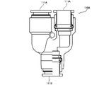
- FIG. 16 is a partial cross-sectional view of the first joint 110A in the filter unit 10A.
- the filter unit 10A includes two tubes 100A, a first fitting 110A, and a second fitting 120A. Similar to the tube 100 in the first embodiment, the chemical filter CF1 is contained in each tube 100A, and a cap 200 is attached to each opening at both ends of each tube 100A.
- the first joint 110A aggregates the first end 101 of each of the plurality of tubes 100A.
- the first joint 110A includes a plurality of tube connecting portions 111A connected to the first end portion 101 of the tube 100A, and one device connecting portion 111B to which a device for discharging compressed air is directly or indirectly connected.
- the second joint 120A aggregates the second end 102 of each of the plurality of tubes 100A.
- the structure of the second joint 120A is the same as the structure of the first joint 110A.
- the second fitting 120A has a plurality of tube connecting portions 121A and one device connecting portion 121B.
- the chemical filter CF1 is dispersed in a plurality of tubes 100A. Therefore, when the amount of the chemical filter CF1 is the same, the thickness of each tube 100A can be made thinner than when the number of tubes 100 is one. As a result, according to the filter unit 10A, the filter unit 10A can be bent more easily and thinner.
- the shape of the cap 200 in the first embodiment is not limited to the shapes shown in FIGS. 3, 4 and 5.
- the taper 220 does not necessarily have to be provided.
- the taper 220 may be formed in the entire area from the tip portion 210A to the rear end portion 210B of the tubular portion 210, or may be formed only in the vicinity of the rear end portion 210B.
- each of the first joint 110 and the second joint 120 is a so-called one-touch joint.
- each of the first joint 110 and the second joint 120 does not necessarily have to be a one-touch joint.
- Each of the first joint 110 and the second joint 120 may be, for example, any joint as long as the pipe can be connected from both directions.
- the mesh portion 240X is formed between the tip portion 210XA and the rear end portion 210YA of the tubular portion 210X, but the position where the mesh portion 240 is formed in the cap 200X is determined. It can be changed arbitrarily.
- the mesh portion 240 may be formed on the flange portion 230X, or may be formed so as to straddle the flange portion 230X and the tubular portion 210X.
- Filter unit 100 Tube 101 1st end 101X Opening 102 2nd end 102X Opening 110 1st joint 120 2nd joint 200 Cap 210 Cylindrical part 210A Tip 210XA Tip 210B Rear end 210YA Rear end 220 Tapered 230 Flange 240 Mesh CF1 Chemical filter SL1 Seal
Landscapes
- Chemical & Material Sciences (AREA)
- Chemical Kinetics & Catalysis (AREA)
- Engineering & Computer Science (AREA)
- Analytical Chemistry (AREA)
- General Chemical & Material Sciences (AREA)
- Oil, Petroleum & Natural Gas (AREA)
- General Engineering & Computer Science (AREA)
- Mechanical Engineering (AREA)
- Filtering Of Dispersed Particles In Gases (AREA)
Priority Applications (4)
| Application Number | Priority Date | Filing Date | Title |
|---|---|---|---|
| EP21882759.0A EP4230281A4 (en) | 2020-10-19 | 2021-10-18 | Filter unit |
| JP2022557511A JPWO2022085618A1 (https=) | 2020-10-19 | 2021-10-18 | |
| KR1020237009024A KR20230051554A (ko) | 2020-10-19 | 2021-10-18 | 필터 유닛 |
| CN202180067688.3A CN116348701A (zh) | 2020-10-19 | 2021-10-18 | 过滤器单元 |
Applications Claiming Priority (2)
| Application Number | Priority Date | Filing Date | Title |
|---|---|---|---|
| JP2020175100 | 2020-10-19 | ||
| JP2020-175100 | 2020-10-19 |
Publications (1)
| Publication Number | Publication Date |
|---|---|
| WO2022085618A1 true WO2022085618A1 (ja) | 2022-04-28 |
Family
ID=81290456
Family Applications (1)
| Application Number | Title | Priority Date | Filing Date |
|---|---|---|---|
| PCT/JP2021/038386 Ceased WO2022085618A1 (ja) | 2020-10-19 | 2021-10-18 | フィルタユニット |
Country Status (6)
| Country | Link |
|---|---|
| EP (1) | EP4230281A4 (https=) |
| JP (1) | JPWO2022085618A1 (https=) |
| KR (1) | KR20230051554A (https=) |
| CN (1) | CN116348701A (https=) |
| TW (1) | TWI904263B (https=) |
| WO (1) | WO2022085618A1 (https=) |
Families Citing this family (1)
| Publication number | Priority date | Publication date | Assignee | Title |
|---|---|---|---|---|
| KR20240154961A (ko) | 2023-04-19 | 2024-10-28 | 주식회사 엘지에너지솔루션 | 전기화학소자용 자립형 세라믹 분리막 및 이를 포함하는 전기화학소자 |
Citations (12)
| Publication number | Priority date | Publication date | Assignee | Title |
|---|---|---|---|---|
| JPS5193837U (https=) * | 1975-03-03 | 1976-07-28 | ||
| JPS5381645U (https=) * | 1976-12-10 | 1978-07-06 | ||
| JPH0474590U (https=) * | 1990-10-22 | 1992-06-30 | ||
| JPH09196269A (ja) * | 1996-01-19 | 1997-07-29 | Smc Corp | 管継手 |
| JPH1052615A (ja) * | 1996-08-12 | 1998-02-24 | Takenaka Komuten Co Ltd | ろ過装置 |
| JPH10296054A (ja) * | 1997-04-23 | 1998-11-10 | Koa Corp:Kk | オゾン分解装置 |
| JP2002210456A (ja) * | 2001-01-18 | 2002-07-30 | Ngk Insulators Ltd | 浄水器用活性炭パック |
| US20050199126A1 (en) * | 2004-03-15 | 2005-09-15 | Arno Michael J. | Flexible, inline, point-of-use air/gas filter/dryer |
| JP2006263545A (ja) | 2005-03-23 | 2006-10-05 | Toshiba Corp | 塩化水素ガス吸収材および塩化水素ガスの除去方法 |
| JP2007120671A (ja) * | 2005-10-28 | 2007-05-17 | Ngk Spark Plug Co Ltd | 管継手及び圧力変動吸着方法による酸素濃縮装置 |
| JP2012075994A (ja) * | 2010-09-30 | 2012-04-19 | Toei Sangyo Kk | 有害物質除去デバイス、気体又は液体の浄化・精製システム、及び気体又は液体の化学反応システム |
| JP2019051519A (ja) * | 2018-12-19 | 2019-04-04 | 東芝エネルギーシステムズ株式会社 | 水素処理装置 |
Family Cites Families (8)
| Publication number | Priority date | Publication date | Assignee | Title |
|---|---|---|---|---|
| JPH11221414A (ja) * | 1998-02-09 | 1999-08-17 | Mitsubishi Electric Corp | 空気清浄フィルタユニット |
| US7314508B2 (en) * | 2002-08-16 | 2008-01-01 | Flow Dry Technology, Inc. | Desiccant cartridge with seal |
| US7285156B2 (en) * | 2004-03-15 | 2007-10-23 | Michael J. Arno | Inline, point-of-use air/gas dryness indicator |
| US7407632B2 (en) * | 2004-05-28 | 2008-08-05 | Oxysure Systems, Inc. | Apparatus and delivery of medically pure oxygen |
| US20060230629A1 (en) * | 2005-04-16 | 2006-10-19 | Arno Michael J | Wearable disposable dryer with carrying strap and stowage accessory |
| US20080005919A1 (en) * | 2006-07-10 | 2008-01-10 | Brown Jerome R | In-line dryer |
| US10695520B2 (en) * | 2011-04-22 | 2020-06-30 | Inogen, Inc. | Gas concentrator with removable cartridge adsorbent beds |
| CN210237107U (zh) * | 2019-06-21 | 2020-04-03 | 北京牧晨机电有限公司 | 火车槽车装卸鹤管用复合型密封帽及装卸鹤管 |
-
2021
- 2021-10-18 KR KR1020237009024A patent/KR20230051554A/ko active Pending
- 2021-10-18 TW TW110138576A patent/TWI904263B/zh active
- 2021-10-18 EP EP21882759.0A patent/EP4230281A4/en active Pending
- 2021-10-18 WO PCT/JP2021/038386 patent/WO2022085618A1/ja not_active Ceased
- 2021-10-18 CN CN202180067688.3A patent/CN116348701A/zh active Pending
- 2021-10-18 JP JP2022557511A patent/JPWO2022085618A1/ja active Pending
Patent Citations (12)
| Publication number | Priority date | Publication date | Assignee | Title |
|---|---|---|---|---|
| JPS5193837U (https=) * | 1975-03-03 | 1976-07-28 | ||
| JPS5381645U (https=) * | 1976-12-10 | 1978-07-06 | ||
| JPH0474590U (https=) * | 1990-10-22 | 1992-06-30 | ||
| JPH09196269A (ja) * | 1996-01-19 | 1997-07-29 | Smc Corp | 管継手 |
| JPH1052615A (ja) * | 1996-08-12 | 1998-02-24 | Takenaka Komuten Co Ltd | ろ過装置 |
| JPH10296054A (ja) * | 1997-04-23 | 1998-11-10 | Koa Corp:Kk | オゾン分解装置 |
| JP2002210456A (ja) * | 2001-01-18 | 2002-07-30 | Ngk Insulators Ltd | 浄水器用活性炭パック |
| US20050199126A1 (en) * | 2004-03-15 | 2005-09-15 | Arno Michael J. | Flexible, inline, point-of-use air/gas filter/dryer |
| JP2006263545A (ja) | 2005-03-23 | 2006-10-05 | Toshiba Corp | 塩化水素ガス吸収材および塩化水素ガスの除去方法 |
| JP2007120671A (ja) * | 2005-10-28 | 2007-05-17 | Ngk Spark Plug Co Ltd | 管継手及び圧力変動吸着方法による酸素濃縮装置 |
| JP2012075994A (ja) * | 2010-09-30 | 2012-04-19 | Toei Sangyo Kk | 有害物質除去デバイス、気体又は液体の浄化・精製システム、及び気体又は液体の化学反応システム |
| JP2019051519A (ja) * | 2018-12-19 | 2019-04-04 | 東芝エネルギーシステムズ株式会社 | 水素処理装置 |
Non-Patent Citations (1)
| Title |
|---|
| See also references of EP4230281A4 |
Also Published As
| Publication number | Publication date |
|---|---|
| CN116348701A (zh) | 2023-06-27 |
| JPWO2022085618A1 (https=) | 2022-04-28 |
| EP4230281A4 (en) | 2025-06-18 |
| EP4230281A1 (en) | 2023-08-23 |
| TWI904263B (zh) | 2025-11-11 |
| TW202220744A (zh) | 2022-06-01 |
| KR20230051554A (ko) | 2023-04-18 |
Similar Documents
| Publication | Publication Date | Title |
|---|---|---|
| US11920828B2 (en) | System and method for photoelectrochemical air purification | |
| CN1124172C (zh) | 带有成型吸附剂的过滤装置、设备和使用方法 | |
| CN103824987B (zh) | 电池壳体 | |
| US8821619B2 (en) | Adsorbent cartridge assembly with end cap | |
| CN101743051B (zh) | 具有填充口的污染物控制过滤器 | |
| JP7034581B2 (ja) | 通気部材 | |
| WO2022085618A1 (ja) | フィルタユニット | |
| KR20190008861A (ko) | 연료 전지 필터 장치 및 연료 전지 필터 장치가 구비된 연료 전지 필터 시스템 | |
| JP5075669B2 (ja) | 中空糸膜モジュール | |
| JP2006312140A (ja) | 脱気装置 | |
| US7837870B2 (en) | Ion-removing apparatus | |
| CN106573192A (zh) | 褶皱式过滤器、褶皱式滤筒以及均使用褶皱式过滤器的压载水处理装置和压载水处理方法 | |
| JP2007048585A (ja) | 筐体の通気構造 | |
| JP6863272B2 (ja) | 浄水カートリッジ | |
| JP4285263B2 (ja) | 中空糸膜モジュールの製造方法 | |
| JP2006190656A (ja) | 通気部材とこれを用いた通気筐体および電装部品 | |
| CN210543955U (zh) | 一种空气滤芯 | |
| JP6557570B2 (ja) | 流体フィルター | |
| EP4349451A1 (en) | Adsorption device | |
| CN215138039U (zh) | 一种复合过滤器及空气净化装置 | |
| US20230356128A1 (en) | Adsorbent filter assembly | |
| KR102720995B1 (ko) | 활성탄이 충진된 정화 필터 및 활성탄이 충진된 정화 필터의 제조 방법 | |
| CN216671710U (zh) | 对用于燃料电池的流体去离子的过滤器组件和过滤器元件 | |
| CN212790236U (zh) | 一种新型过滤吸收器 | |
| KR101351292B1 (ko) | 필터용 여재 및 이의 제조 방법 |
Legal Events
| Date | Code | Title | Description |
|---|---|---|---|
| 121 | Ep: the epo has been informed by wipo that ep was designated in this application |
Ref document number: 21882759 Country of ref document: EP Kind code of ref document: A1 |
|
| ENP | Entry into the national phase |
Ref document number: 2022557511 Country of ref document: JP Kind code of ref document: A |
|
| ENP | Entry into the national phase |
Ref document number: 20237009024 Country of ref document: KR Kind code of ref document: A |
|
| NENP | Non-entry into the national phase |
Ref country code: DE |
|
| ENP | Entry into the national phase |
Ref document number: 2021882759 Country of ref document: EP Effective date: 20230519 |