WO2022085597A1 - 粉粒体供給装置 - Google Patents
粉粒体供給装置 Download PDFInfo
- Publication number
- WO2022085597A1 WO2022085597A1 PCT/JP2021/038293 JP2021038293W WO2022085597A1 WO 2022085597 A1 WO2022085597 A1 WO 2022085597A1 JP 2021038293 W JP2021038293 W JP 2021038293W WO 2022085597 A1 WO2022085597 A1 WO 2022085597A1
- Authority
- WO
- WIPO (PCT)
- Prior art keywords
- powder
- granular material
- supply
- stocker
- main body
- Prior art date
- Legal status (The legal status is an assumption and is not a legal conclusion. Google has not performed a legal analysis and makes no representation as to the accuracy of the status listed.)
- Ceased
Links
Images
Classifications
-
- B—PERFORMING OPERATIONS; TRANSPORTING
- B65—CONVEYING; PACKING; STORING; HANDLING THIN OR FILAMENTARY MATERIAL
- B65G—TRANSPORT OR STORAGE DEVICES, e.g. CONVEYORS FOR LOADING OR TIPPING, SHOP CONVEYOR SYSTEMS OR PNEUMATIC TUBE CONVEYORS
- B65G65/00—Loading or unloading
- B65G65/30—Methods or devices for filling or emptying bunkers, hoppers, tanks, or like containers, of interest apart from their use in particular chemical or physical processes or their application in particular machines, e.g. not covered by a single other subclass
- B65G65/34—Emptying devices
- B65G65/40—Devices for emptying otherwise than from the top
- B65G65/46—Devices for emptying otherwise than from the top using screw conveyors
-
- G—PHYSICS
- G01—MEASURING; TESTING
- G01G—WEIGHING
- G01G19/00—Weighing apparatus or methods adapted for special purposes not provided for in the preceding groups
- G01G19/22—Weighing apparatus or methods adapted for special purposes not provided for in the preceding groups for apportioning materials by weighing prior to mixing them
- G01G19/24—Weighing apparatus or methods adapted for special purposes not provided for in the preceding groups for apportioning materials by weighing prior to mixing them using a single weighing apparatus
- G01G19/30—Weighing apparatus or methods adapted for special purposes not provided for in the preceding groups for apportioning materials by weighing prior to mixing them using a single weighing apparatus having electrical weight-sensitive devices
-
- B—PERFORMING OPERATIONS; TRANSPORTING
- B65—CONVEYING; PACKING; STORING; HANDLING THIN OR FILAMENTARY MATERIAL
- B65G—TRANSPORT OR STORAGE DEVICES, e.g. CONVEYORS FOR LOADING OR TIPPING, SHOP CONVEYOR SYSTEMS OR PNEUMATIC TUBE CONVEYORS
- B65G65/00—Loading or unloading
- B65G65/30—Methods or devices for filling or emptying bunkers, hoppers, tanks, or like containers, of interest apart from their use in particular chemical or physical processes or their application in particular machines, e.g. not covered by a single other subclass
- B65G65/34—Emptying devices
- B65G65/40—Devices for emptying otherwise than from the top
-
- B—PERFORMING OPERATIONS; TRANSPORTING
- B65—CONVEYING; PACKING; STORING; HANDLING THIN OR FILAMENTARY MATERIAL
- B65G—TRANSPORT OR STORAGE DEVICES, e.g. CONVEYORS FOR LOADING OR TIPPING, SHOP CONVEYOR SYSTEMS OR PNEUMATIC TUBE CONVEYORS
- B65G69/00—Auxiliary measures taken, or devices used, in connection with loading or unloading
-
- G—PHYSICS
- G01—MEASURING; TESTING
- G01G—WEIGHING
- G01G13/00—Weighing apparatus with automatic feed or discharge for weighing-out batches of material
- G01G13/02—Means for automatically loading weigh pans or other receptacles, e.g. disposable containers, under control of the weighing mechanism
-
- B—PERFORMING OPERATIONS; TRANSPORTING
- B65—CONVEYING; PACKING; STORING; HANDLING THIN OR FILAMENTARY MATERIAL
- B65G—TRANSPORT OR STORAGE DEVICES, e.g. CONVEYORS FOR LOADING OR TIPPING, SHOP CONVEYOR SYSTEMS OR PNEUMATIC TUBE CONVEYORS
- B65G2201/00—Indexing codes relating to handling devices, e.g. conveyors, characterised by the type of product or load being conveyed or handled
- B65G2201/04—Bulk
- B65G2201/042—Granular material
Definitions
- the present invention relates to a powder or granular material supply device, and more particularly to a powder or granular material supply device having a leakage prevention unit.
- the powder / granular material supply device that supplies the powder / granular material
- the powder / granular material remains in the vicinity of the supply port, and therefore the powder remaining in the vicinity of the supply port due to vibration or the like.
- the granules will collapse and the powder or granules will spill from the supply port.
- the supply of the powder or granular material is also stopped immediately after the drive of the powder or granular material supply device is stopped.
- the powder or granular material supply device is stopped. Even after the drive of the powder or granular material is stopped, the supply of the powder or granular material does not stop immediately, and the powder or granular material remaining in the vicinity of the supply port continues to be unintentionally supplied.
- Patent Document 1 in a powder or granular material supply device for supplying powder or granular material, a casing having an internal space for accommodating the powder or granular material and an upstream side are connected to the casing.
- a lid portion that is in close contact with the opening and an air flow that pushes the powder or granular material at the downstream end portion of the transport pipe back to the upstream side while the lid portion is in close contact with the opening are flowed.
- a granular material supply device comprising a vent.
- Patent Document 1 requires a device such as a suction blower because the pressure in the transport path is changed when the lid is opened and closed. Therefore, the number of required devices increases and the device structure becomes complicated.
- the simple structure catches the powder or granular material spilling from the supply port when the supply of the powder or granular material is stopped, and hinders the supply of the powder or granular material from the powder or granular material supply device when the powder or granular material is supplied. It is an object of the present invention to provide a powder or granular material supply device having a non-leakage prevention unit.
- the present invention comprises a main body, a plurality of stockers that can be connected to the main body and that store the powder or granular material inside, and a plurality of leakage prevention portions, and the stocker is the powder or granular material inside the stocker. It has an input port capable of charging the powder, and a supply unit which has a supply port and supplies the powder or granular material stored in the stocker from the supply port, and the leakage prevention unit is the supply port. It has a receiving member capable of receiving the spilled powder or granular material and a driving portion for moving the receiving member, and the receiving member receives the powder or granular material spilled from the supply port by the driving unit. It is a powder or granular material supply device characterized in that it can be moved to a first position where it can be received and a second position where the powder or granular material can be supplied from the supply port.
- the stocker can supply the powder or granular material stored inside from the supply port of the supply unit, and the receiving member can receive the powder or granular material.
- the drive unit can move the position of the receiving member.
- the receiving member of the leakage prevention unit can receive the powder or granular material spilling from the supply port of the supply unit by the drive unit of the leakage prevention unit. It is possible to be located at the first position, and the receiving member can prevent the powder or granular material from leaking from the supply port.
- the receiving member of the leakage prevention unit can supply the powder or granular material from the supply port of the supply unit by the drive unit of the leakage prevention unit. It is possible to be located at a second position, and the supply unit can supply the powder or granular material without being hindered by the receiving member.
- powder / granular material includes any of powders, granules, or a mixture of powders and granules. Applications of powders and granules are not limited, such as foods, chemicals, construction / civil engineering, and semiconductors.
- “Supplying powder or granular material from the supply port” means discharging the powder or granular material from the supply port to the outside of the stocker. For example, the discharged powder or granular material is dropped into a container and stored, and is supplied for the purpose of weighing the powder or granular material in the container with a measuring instrument.
- Leakage means that when the stocker does not supply the powder or granular material from the supply port, the powder or granular material is spilled from the supply port due to vibration or the like, and the powder or granular material is unintentionally supplied. The amount of spillage is affected by the angle of repose of the granules.
- supply unit examples include a screw conveyor and a screw feeder, but other powder and granular material supply units such as a vibration feeder and a belt conveyor can also be adopted as long as they have a powder or granular material transfer function. ..
- the "receiving member” is an example of a box-shaped body, a dish-shaped body, or the like having an opening at the top, and has a structure that can receive and hold the powder or granular material inside.
- the "drive unit” is not particularly limited, and existing ones can be used, and examples thereof include a hydraulic cylinder, a pneumatic cylinder, and a motor.
- receiving the powder or granular material means receiving the powder or granular material spilled from the supply port and holding it in the member.
- the powder or granular material can be supplied from the supply port means that the powder or granular material discharged from the supply port can be supplied without being hindered by the receiving member.
- the present invention has a structure in which a plurality of stockers are arranged radially around the main body, the supply ports are arranged so as to face the center of the main body, and the stockers are detachably connected to the main body. Is preferable. According to this configuration, the stocker provided in the powder or granular material supply device and another stocker can be exchanged, and the powder or granular material supplied from the powder or granular material supply device can be replaced with another stocker. The work of switching to powder or granular material is simplified. Further, the structure in which the stocker is detachably connected to the main body improves the maintainability of the powder or granular material supply device.
- the supply unit when the supply unit supplies the powder or granular material, it is preferable to supply the powder or granular material accumulated in the receiving member. According to this configuration, it is possible to supply the powder or granular material accumulated in the receiving member, and the yield can be improved. Further, the work of removing the powder or granular material accumulated in the receiving member becomes unnecessary. Further, since the receiving member can be moved from the second position to the first position in an empty state, it is possible to prevent the powder or granular material from spilling from the receiving member.
- the present invention has a structure in which the main body includes a main body portion and a pedestal for supporting the main body portion, and the stocker can be attached to and detached from the pedestal, and the powder or granular material is supplied to the main body portion by the supply portion. It is preferable to include a control unit that controls the driving of the driving unit. According to this configuration, the powder or granular material can be supplied in the region of the gantry, and the supply of the powder or granular material and the control efficiency of the drive unit are improved.
- the supply port is arranged above the upper opening of the container for measuring the powder or granular material, and the receiving member can move above the upper opening. According to this configuration, the accuracy of weighing the powder or granular material is high.
- the present invention with a simple structure, when the supply of powder or granular material is stopped, the powder or granular material spilling from the supply port of the powder or granular material supply device is received, and when the powder or granular material is supplied, it is not hindered by the leakage prevention unit. It is possible to supply powders and granules.
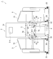
- the powder or granular material supply device 1 (hereinafter referred to as the supply device 1) will be described with reference to FIGS. 1 to 4.
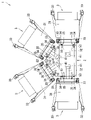
- the supply device 1 stores the main body 2 and the powder or granular material inside, and can supply the stored powder or granular material, and has a plurality of stockers 3 that can be connected to the main body 2 and a plurality of leakage prevention units 4. It is a configuration including.
- the supply device 1 also includes a measuring instrument 6 and a container 7.
- description will be made with reference to the drawings.
- the main body 2 includes a main body portion 21 and a gantry 5 that supports the main body portion 21, and has a structure in which the stocker 3 can be attached to and detached from the gantry portion 5.
- the main body 21 includes a control unit 211.
- the control unit 211 controls the supply of the powder or granular material by the supply unit 32, which will be described later, and the drive of the drive unit 42, which will be described later, by connecting the main body 2 to the stocker 3.
- the control can be performed manually or automatically by configuration.
- the gantry 5 has a mounting portion 51 and a plurality of leg portions 52.
- the leg portion 52 has a guide receiving portion 53, and the stocker 3 is connected to the main body 2 by fitting the guide receiving portion 53 and the guide portion 35 of the stocker 3 described later.
- the gantry 5 of the present embodiment can be connected to four stockers 3.
- the main body 21 is mounted on the upper part of the mounting portion 51 of the gantry 5 whose inside is hollow.
- the stocker 3 has an input port 31 capable of charging the powder or granular material into the stocker 3, and a supply unit 32 for supplying the powder or granular material stored inside the stocker 3 from the supply port 321.
- the position for supplying the powder or granular material from the supply port 321 to the container 7 is preset.
- the supply unit 32 of the present embodiment is a tubular screw feeder.
- the stocker 3 further has a plurality of casters 33 including one with a rotation stopper at the bottom, an elastic member 34, and a guide portion 35 to be inserted into the main body 2. The stocker 3 can be moved by the caster 33.
- a plurality of stockers 3 are arranged radially around the main body 2 (4 in this case), and the supply ports 321 are arranged so as to face the center of the main body 2.
- the other portion of the supply unit 32 is located in the internal space of the stocker 3, and the powder or granular material stored in the stocker 3 is supplied to the inside of the stocker 32 from the opening of the stocker 32.
- the stocker 3 has a structure that is detachably connected to the main body 2.
- a mechanical insertion structure can be exemplified.
- the stocker 3 is pushed into the main body 2, the guide portion 35 is inserted into the main body 2, and the stocker 3 is attached to the main body 2.
- the stocker 3 is pulled out from the main body 2, the guide portion 35 is pulled away from the main body 2, and the stocker 3 is separated from the main body 2.
- the guide portion 35 is inserted into the main body 2 and is fitted with the guide receiving portion 53.
- the stocker 3 and the main body 2 are fixed, and it is possible to prevent the supply port 321 from being displaced.
- the elastic member 34 is a member that has elasticity and cushions impact, is located outside the guide portion 35, and is in contact with the main body 2 when the stocker 3 is attached to the main body 2.
- the elastic member 34 can prevent the stocker 3 itself from coming into contact with the main body 2 and being damaged when the stocker 3 receives an unexpected impact from the outside.
- the stocker 3 can be exchanged with another stocker 3, it becomes easy to switch the powder or granular material to be supplied. Since the stocker 3 can be detached from the main body 2, maintenance can be performed with the stocker 3 detached from the main body 2, and the maintainability of the supply device 1 is improved. For example, if the supply unit 32 or the leak prevention unit 4 fails, repair and replacement is easy.
- the leak prevention unit 4 has a receiving member 41 capable of receiving powder particles spilling from the supply port 321 and a driving unit 42 for moving the receiving member 41.
- the receiving member 41 is a box-shaped member having an opening 411 with an opening at the upper side.
- the leak prevention unit 4 is a member that extends laterally.
- the leakage prevention unit 4 of the present embodiment is arranged below the supply unit 32, and one end thereof is fixed to the leg portion 52 of the gantry 5, but the installation position is not particularly limited, and the receiving member 41 will be described later. Any position that can be located at the first position A and the second position B can be adopted.
- the receiving member 41 is connected to the drive unit 42 with the opening 411 facing upward. This makes it possible to catch the powder or granular material falling from above.
- the receiving member 41 preferably has a shape in which the opening 411 expands upward. This makes it possible to improve the effect of preventing the leakage of the powder or granular material from the supply port 321 of the supply unit 32.
- the shape of the receiving member 41 is not particularly limited as long as it has an opening 411 and can receive the powder or granular material discharged from the supply port 321.
- a rectangular parallelepiped, a circular body, an ellipsoid, a polygonal body, etc., in which the opening 411 faces upward can be mentioned.
- the size of the receiving member 41 is not particularly limited as long as it is large enough to receive the powder or granular material spilling from the supply port 321, but from the viewpoint of preventing interference with other members such as the other receiving member 41. However, its size is determined.
- the material of the receiving member 41 is not particularly limited, and an existing material can be appropriately used depending on the characteristics of the powder or granular material.
- existing metal materials such as thermosetting resin, thermoplastic resin, and stainless steel can be used.
- the drive unit 42 can move what is connected.
- the drive unit 42 of the present embodiment is a power cylinder, and the receiving member 41 is connected to the tip of the piston rod 421 extending from the inside of the power cylinder via an L-shaped member. Further, by using the power cylinder, the receiving member 41 can be moved by hydraulic pressure or pneumatic pressure. Examples of the drive unit 42 include a motor in addition to the power cylinder, but the drive unit 42 is not particularly limited.
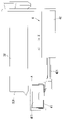
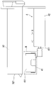
- the drive unit 42 places the receiving member 41 at the first position A (position where the powder or granular material spilling from the supply port 321 can be received, see FIG. 3) along the axial direction X of the supply unit 32. It is possible to move to the second position B (position where the powder or granular material can be supplied from the supply port 321; see FIG. 4).
- the supply port 321 is located above the receiving member 41 at the first position A, and is located diagonally above the front wall of the receiving member 41 at the second position B.
- the drive unit 42 and the supply unit 32 are a power cylinder and a cylindrical screw feeder, respectively, and the piston rod 421 of the power cylinder can be expanded and contracted in the same direction as the axial direction X of the screw (not shown) of the screw feeder. ..
- the receiving member 41 connected to the tip of the piston rod 421 of the power cylinder, which is the driving unit 42, can move in the same direction as the axial direction X of the screw of the screw feeder, whereby the receiving member 41 can move. , The first position A and the second position B can be moved.
- the receiving member 41 When the supply unit 32 does not supply the powder or granular material, as shown in FIG. 3, the receiving member 41 is in the first position A where the powder or granular material spilled from the supply port 321 by the drive unit 42 can be received. To position. Therefore, as shown in FIGS. 2 and 3, the receiving member 41 of the leakage prevention unit 4 can catch the powder or granular material spilling from the supply port 321.
- the receiving member 41 is located at the second position B where the powder or granular material can be supplied from the supply port 321 by the drive unit 42. .. Therefore, it is possible to supply the powder or granular material from the supply port 321 without being received by the receiving member 41 of the leakage prevention unit 4.
- the measuring instrument 6 and the container 7 for measuring which can store powders and granules and are placed above the measuring instrument 6, are arranged inside the gantry 5.
- the stocker 3 is attached to the main body 2 with the vicinity of the tip of the supply unit 32 including the supply port 321 inserted inside the gantry 5, and the supply port 321 is above the container 7.
- It is located above the upper opening 71 of the container 7, which is a place where the powder or granular material can be supplied to the inside of the container 7.
- the receiving member 41 is movable above the upper opening 71 and below the supply port 321.
- the measuring instrument 6 can measure the weight of the powder or granular material supplied from the supply device 1 and stored in the container 7. By connecting the main body 2 and the measuring instrument 6 with a cable (not shown), the main body 2 can be used from the stocker 3 according to the weight of the powder or granular material stored in the container 7 measured by the measuring instrument 6. It is also possible to control the supply flow rate of the powder or granular material to be supplied.
- a measuring instrument 6 having a conveyor capable of transporting the container 7 on the upper portion thereof can also be adopted. By adopting such a measuring instrument 6, the container 7 can be easily transported and installed. Examples of the conveyor include a roller conveyor and a belt conveyor.
- the supply device 1 can control the supply flow rate of the powder or granular material supplied from the stocker 3 by the main body 2 described above, and the receiving member 41 of the leakage prevention unit 4 receives the powder or granular material spilling from the supply port 321. By being able to do so, it is possible to accurately supply a predetermined weight of powder or granular material from the stocker 3 to the container 7.
- the operation procedure of the supply device 1 will be explained.
- the stocker 3 is attached to the main body 2.
- the number of stockers 3 to be mounted on the main body 2 is arbitrary, and the number of stockers 3 to be mounted can be determined in consideration of the type, amount, and the like of the powder or granular material to be supplied.
- the timing of charging the powder or granular material stored inside the stocker 3 into the stocker 3 may be any time before the powder or granular material is supplied, but from the viewpoint of operability, after the powder or granular material is charged into the stocker 3, the stocker 3 is charged. It is preferable to attach 3 to the main body 2.
- the receiving member 41 of the leakage prevention unit 4 When the stocker 3 is not attached to the main body 2, the receiving member 41 of the leakage prevention unit 4 is located at the first position A. Even if the stocker 3 is attached to the main body 2, if the supply of powder or granular material is not started from the stocker 3, the receiving member 41 of the leakage prevention unit 4 is similarly in the first position. It is located in A. As a result, even if the powder or granular material spills from the supply port 321 when the stocker 3 is attached to the main body 2, the powder or granular material is received by the receiving member 41 located at the first position A. Therefore, it is possible to prevent the leakage of the powder or granular material.
- the control unit 211 of the main body 2 Operate the control unit 211 of the main body 2 to supply the powder or granular material from the stocker 3 mounted on the main body 2.
- the receiving member 41 located below the stocker 3 for supplying the powder or granular material is placed in the first position A to the second position B before the powder or granular material is supplied from the supply port 321 by the drive unit 42. Move to. This makes it possible to supply the powder or granular material from the stocker 3 without being hindered by the receiving member 41.
- the receiving member 41 located below the stocker 3 that stops the supply of the powder or granular material is the first from the second position B after the supply of the powder or granular material from the supply port 321 is stopped by the drive unit 42. Move to position A of.
- the powder or granular material is the first. Since it is received by the receiving member 41 located at the position A, it is possible to prevent the leakage of the powder or granular material.
- the receiving member 41 located below the other stocker 3 is , Remains located in the first position A.
- the powder or granular material spilling from the supply port 321 of the other stocker 3 is received by the receiving member 41, and the leakage of the powder or granular material can be prevented.
- the supply of the powder or granular material from the stocker 3 may be started and stopped by repeating an arbitrary number of times depending on the situation of the supply work. At that time, since the receiving member 41 located below the stocker 3 is moved each time the supply of the powder or granular material from the stocker 3 is started or stopped, it is possible to prevent the powder or granular material from leaking in the same manner. Is.
- each stocker 3 supplies the powder or granular material one by one.
- the receiving member 41 located below the stocker 3 that supplies the powder or granular material is located at the second position B, and the receiving member 41 located below the stocker 3 that does not supply the powder or granular material is the first. It is located at position A of. Thereby, the weight of the powder or granular material supplied from each stocker 3 to the container 7 can be measured.
- the measuring instrument 6 determines that the weight of the powder or granular material stored in the container 7 has reached the set weight, the powder or granular material supply process is completed, the container 7 is carried out, and a new container 7 is installed. The following powder or granular material supply processing is performed.
- the stocker 3 After completing all the powder and granular material supply processing, the stocker 3 is separated from the main body 2. At this time, since the supply of the powder or granular material from the stocker 3 is stopped, the receiving member 41 located below the stocker 3 is located at the first position A. As a result, even if the powder or granular material spills from the supply port 321 when the stocker 3 is detached from the main body 2, the powder or granular material is received by the receiving member 41 located at the first position A. Therefore, it is possible to prevent the leakage of the powder or granular material.
- the receiving member 41 located below the stocker 3 is further rotated or the like to collect the powder or granular material in the receiving member 41. It is possible to supply the body to the container 7.
- the yield can be improved by supplying the powder or granular material accumulated in the receiving member 41. Further, when the supply of the powder or granular material from the stocker 3 is stopped, the empty receiving member 41 can be moved from the first position A to the second position B, so that the receiving member 41 can be moved. It is also possible to prevent the powder or granular material from spilling.
- the method of supplying the powder or granular material accumulated in the receiving member 41 is not particularly limited.
- a method in which the bottom surface of the receiving member 41 is a door, a method of opening the door, a method of rotating the receiving member 41 so that powder particles collected in the receiving member 41 are dropped and supplied from the opening 411, and the like. can be mentioned.
- the receiving member 41 located below the stocker 3 for supplying the powder or granular material rotates and accumulates in the receiving member 41.
- Supply granules After that, the leakage prevention unit 4 returns to the original position, so that the receiving member 41 returns to a state where it can receive the powder or granular material.
- the drive unit 42 moves the powder or granular material from the first position A to the second position B before being supplied from the supply port 321. This makes it possible to supply the powder or granular material from the stocker 3 without being hindered by the receiving member 41.
- the present invention is not limited to the above-described embodiment, and modifications and the like can be added within a range that does not deviate from the technical idea of the present invention. It will be included in the technical scope.
- the number of stockers 3 attached to the main body 2 is four in the above embodiment, but an appropriate number such as 1, 2, 3, 5, ... Can be adopted.
- the leakage prevention unit 4 is used to measure the weight of the powder or granular material supplied to the container 7, but it can also be applied to the powder or granular material processing equipment for other purposes.
Landscapes
- Engineering & Computer Science (AREA)
- Mechanical Engineering (AREA)
- Physics & Mathematics (AREA)
- General Physics & Mathematics (AREA)
- Filling Or Emptying Of Bunkers, Hoppers, And Tanks (AREA)
Priority Applications (5)
| Application Number | Priority Date | Filing Date | Title |
|---|---|---|---|
| EP21882738.4A EP4230558A4 (en) | 2020-10-19 | 2021-10-15 | PARTICULATE MATTER DISTRIBUTION DEVICE |
| KR1020227036752A KR102807498B1 (ko) | 2020-10-19 | 2021-10-15 | 분립체 공급장치 |
| CN202180031331.XA CN115485220B (zh) | 2020-10-19 | 2021-10-15 | 粉粒体供给装置 |
| JP2022557490A JP7387210B2 (ja) | 2020-10-19 | 2021-10-15 | 粉粒体供給装置 |
| US18/050,503 US12145812B2 (en) | 2020-10-19 | 2022-10-28 | Particulate material supply apparatus |
Applications Claiming Priority (2)
| Application Number | Priority Date | Filing Date | Title |
|---|---|---|---|
| JP2020-175451 | 2020-10-19 | ||
| JP2020175451 | 2020-10-19 |
Related Child Applications (1)
| Application Number | Title | Priority Date | Filing Date |
|---|---|---|---|
| US18/050,503 Continuation US12145812B2 (en) | 2020-10-19 | 2022-10-28 | Particulate material supply apparatus |
Publications (1)
| Publication Number | Publication Date |
|---|---|
| WO2022085597A1 true WO2022085597A1 (ja) | 2022-04-28 |
Family
ID=81290538
Family Applications (1)
| Application Number | Title | Priority Date | Filing Date |
|---|---|---|---|
| PCT/JP2021/038293 Ceased WO2022085597A1 (ja) | 2020-10-19 | 2021-10-15 | 粉粒体供給装置 |
Country Status (6)
| Country | Link |
|---|---|
| US (1) | US12145812B2 (enExample) |
| EP (1) | EP4230558A4 (enExample) |
| JP (1) | JP7387210B2 (enExample) |
| KR (1) | KR102807498B1 (enExample) |
| CN (1) | CN115485220B (enExample) |
| WO (1) | WO2022085597A1 (enExample) |
Families Citing this family (5)
| Publication number | Priority date | Publication date | Assignee | Title |
|---|---|---|---|---|
| WO2022097611A1 (ja) * | 2020-11-03 | 2022-05-12 | 株式会社ツカサ | 粉体供給装置 |
| JP7732238B2 (ja) * | 2021-06-21 | 2025-09-02 | 新東工業株式会社 | 鋳物砂供給装置及び鋳物砂検査システム |
| USD1059447S1 (en) * | 2022-02-25 | 2025-01-28 | Tsukasa Co., Ltd. | Powder particle weighing machine |
| USD1051190S1 (en) * | 2022-02-25 | 2024-11-12 | Tsukasa Co., Ltd. | Powder particle feeder for weighing |
| JP1729852S (ja) * | 2022-03-29 | 2022-11-15 | 粉粒体計量用供給機 |
Citations (6)
| Publication number | Priority date | Publication date | Assignee | Title |
|---|---|---|---|---|
| JP2002086438A (ja) * | 2000-09-19 | 2002-03-26 | Mitsuishi Fukai Tekkosho:Kk | レンガ成形機への原料供給装置 |
| JP2014213497A (ja) * | 2013-04-24 | 2014-11-17 | 株式会社カワタ | 粉粒体の計量混合装置 |
| JP2018127335A (ja) * | 2017-02-09 | 2018-08-16 | 株式会社夕原テクノグループ | 切り出し秤量装置 |
| JP2019131378A (ja) | 2018-02-01 | 2019-08-08 | 株式会社カワタ | 粉粒体供給装置 |
| CN210135986U (zh) * | 2019-06-05 | 2020-03-10 | 流亚科技有限公司 | 粉体送料精密计量装置 |
| WO2020184632A1 (ja) * | 2019-03-13 | 2020-09-17 | 株式会社イシダ | 組合せ計量装置 |
Family Cites Families (6)
| Publication number | Priority date | Publication date | Assignee | Title |
|---|---|---|---|---|
| JP5219053B2 (ja) * | 2011-10-27 | 2013-06-26 | 株式会社夕原テクノグループ | パイプ回転式食品搬送装置 |
| JP6166880B2 (ja) * | 2012-08-16 | 2017-07-19 | 三光機械株式会社 | 自動包装機用粒状原料供給装置 |
| JP5891507B2 (ja) * | 2013-10-07 | 2016-03-23 | 株式会社夕原テクノグループ | 計量シュート装置 |
| JP6687904B2 (ja) * | 2016-10-31 | 2020-04-28 | 日本電気硝子株式会社 | 粉体原料供給装置 |
| EP3549692A4 (en) * | 2016-11-29 | 2020-04-29 | Sintokogio, Ltd. | POWDER SAND BINDING SUPPLY DEVICE AND BINDING SUPPLY METHOD |
| CN208206214U (zh) * | 2018-03-23 | 2018-12-07 | 四川大学 | 基于步进电机的中药粉末精密计量仪 |
-
2021
- 2021-10-15 CN CN202180031331.XA patent/CN115485220B/zh active Active
- 2021-10-15 JP JP2022557490A patent/JP7387210B2/ja active Active
- 2021-10-15 KR KR1020227036752A patent/KR102807498B1/ko active Active
- 2021-10-15 WO PCT/JP2021/038293 patent/WO2022085597A1/ja not_active Ceased
- 2021-10-15 EP EP21882738.4A patent/EP4230558A4/en active Pending
-
2022
- 2022-10-28 US US18/050,503 patent/US12145812B2/en active Active
Patent Citations (6)
| Publication number | Priority date | Publication date | Assignee | Title |
|---|---|---|---|---|
| JP2002086438A (ja) * | 2000-09-19 | 2002-03-26 | Mitsuishi Fukai Tekkosho:Kk | レンガ成形機への原料供給装置 |
| JP2014213497A (ja) * | 2013-04-24 | 2014-11-17 | 株式会社カワタ | 粉粒体の計量混合装置 |
| JP2018127335A (ja) * | 2017-02-09 | 2018-08-16 | 株式会社夕原テクノグループ | 切り出し秤量装置 |
| JP2019131378A (ja) | 2018-02-01 | 2019-08-08 | 株式会社カワタ | 粉粒体供給装置 |
| WO2020184632A1 (ja) * | 2019-03-13 | 2020-09-17 | 株式会社イシダ | 組合せ計量装置 |
| CN210135986U (zh) * | 2019-06-05 | 2020-03-10 | 流亚科技有限公司 | 粉体送料精密计量装置 |
Non-Patent Citations (1)
| Title |
|---|
| See also references of EP4230558A4 |
Also Published As
| Publication number | Publication date |
|---|---|
| US12145812B2 (en) | 2024-11-19 |
| JP7387210B2 (ja) | 2023-11-28 |
| KR20220157473A (ko) | 2022-11-29 |
| US20230107336A1 (en) | 2023-04-06 |
| KR102807498B1 (ko) | 2025-05-13 |
| JPWO2022085597A1 (enExample) | 2022-04-28 |
| CN115485220B (zh) | 2025-09-26 |
| CN115485220A (zh) | 2022-12-16 |
| EP4230558A4 (en) | 2024-08-14 |
| EP4230558A1 (en) | 2023-08-23 |
Similar Documents
| Publication | Publication Date | Title |
|---|---|---|
| WO2022085597A1 (ja) | 粉粒体供給装置 | |
| US5518344A (en) | Apparatus for transporting powder coating material from a box-shaped container | |
| US20120009046A1 (en) | Device for Emptying Powder Bags for Powder Spraying Apparatus | |
| US10669071B2 (en) | Powder container systems for additive manufacturing | |
| US6273153B1 (en) | Metering and dispensing particulate matter directly into bins | |
| JP2019093361A (ja) | 容器への廃棄物の充填システム | |
| CN116080969B (zh) | 一种多物料自动包装生产线 | |
| KR20010006269A (ko) | 물질 처리용 장치 및 시스템 | |
| JP7100405B1 (ja) | 粉体供給装置 | |
| WO2022097610A1 (ja) | 粉体供給装置 | |
| JP3022448B2 (ja) | 密閉系用粉粒体供給装置 | |
| US3720241A (en) | Means for feeding flowable particulate material | |
| CN112456170A (zh) | 一种用于粉末原料运输转移的装置 | |
| JP7267973B2 (ja) | 粉体の充填計量装置 | |
| JP2016007656A (ja) | ショットブラスト装置 | |
| KR20040012342A (ko) | 쇼트 블라스트의 이물질 분리장치 | |
| JP2012206742A (ja) | コンテナ開閉装置 | |
| JP6738934B2 (ja) | 振動印加方法 | |
| JP5504138B2 (ja) | 振動式粉体切り出し装置 | |
| JP6669349B2 (ja) | 粉体供給装置および粉体供給機構 | |
| JP2017164688A (ja) | 洗浄装置及び粉体充填製品の製造方法 | |
| CN119796950B (zh) | 基于无动力源气力输送自调节粉体物料流量适配装置 | |
| JPH0632908Y2 (ja) | 充填装置 | |
| US20220402019A1 (en) | Molding sand supply device and molding sand inspection system | |
| JP2001170469A (ja) | 粉粒状物質の混合方法 |
Legal Events
| Date | Code | Title | Description |
|---|---|---|---|
| 121 | Ep: the epo has been informed by wipo that ep was designated in this application |
Ref document number: 21882738 Country of ref document: EP Kind code of ref document: A1 |
|
| ENP | Entry into the national phase |
Ref document number: 20227036752 Country of ref document: KR Kind code of ref document: A |
|
| ENP | Entry into the national phase |
Ref document number: 2022557490 Country of ref document: JP Kind code of ref document: A |
|
| NENP | Non-entry into the national phase |
Ref country code: DE |
|
| ENP | Entry into the national phase |
Ref document number: 2021882738 Country of ref document: EP Effective date: 20230519 |