WO2022085472A1 - 薄型基板内蔵ハードディスクドライブ及び薄型基板内蔵ハードディスクドライブ用ベースプレート部材 - Google Patents
薄型基板内蔵ハードディスクドライブ及び薄型基板内蔵ハードディスクドライブ用ベースプレート部材 Download PDFInfo
- Publication number
- WO2022085472A1 WO2022085472A1 PCT/JP2021/037203 JP2021037203W WO2022085472A1 WO 2022085472 A1 WO2022085472 A1 WO 2022085472A1 JP 2021037203 W JP2021037203 W JP 2021037203W WO 2022085472 A1 WO2022085472 A1 WO 2022085472A1
- Authority
- WO
- WIPO (PCT)
- Prior art keywords
- base plate
- mass
- phase particles
- less
- aluminum alloy
- Prior art date
- Legal status (The legal status is an assumption and is not a legal conclusion. Google has not performed a legal analysis and makes no representation as to the accuracy of the status listed.)
- Ceased
Links
Images



Classifications
-
- G—PHYSICS
- G11—INFORMATION STORAGE
- G11B—INFORMATION STORAGE BASED ON RELATIVE MOVEMENT BETWEEN RECORD CARRIER AND TRANSDUCER
- G11B25/00—Apparatus characterised by the shape of record carrier employed but not specific to the method of recording or reproducing, e.g. dictating apparatus; Combinations of such apparatus
- G11B25/04—Apparatus characterised by the shape of record carrier employed but not specific to the method of recording or reproducing, e.g. dictating apparatus; Combinations of such apparatus using flat record carriers, e.g. disc, card
- G11B25/043—Apparatus characterised by the shape of record carrier employed but not specific to the method of recording or reproducing, e.g. dictating apparatus; Combinations of such apparatus using flat record carriers, e.g. disc, card using rotating discs
-
- C—CHEMISTRY; METALLURGY
- C22—METALLURGY; FERROUS OR NON-FERROUS ALLOYS; TREATMENT OF ALLOYS OR NON-FERROUS METALS
- C22C—ALLOYS
- C22C1/00—Making non-ferrous alloys
- C22C1/02—Making non-ferrous alloys by melting
-
- C—CHEMISTRY; METALLURGY
- C22—METALLURGY; FERROUS OR NON-FERROUS ALLOYS; TREATMENT OF ALLOYS OR NON-FERROUS METALS
- C22C—ALLOYS
- C22C21/00—Alloys based on aluminium
-
- C—CHEMISTRY; METALLURGY
- C22—METALLURGY; FERROUS OR NON-FERROUS ALLOYS; TREATMENT OF ALLOYS OR NON-FERROUS METALS
- C22C—ALLOYS
- C22C21/00—Alloys based on aluminium
- C22C21/06—Alloys based on aluminium with magnesium as the next major constituent
-
- G—PHYSICS
- G11—INFORMATION STORAGE
- G11B—INFORMATION STORAGE BASED ON RELATIVE MOVEMENT BETWEEN RECORD CARRIER AND TRANSDUCER
- G11B33/00—Constructional parts, details or accessories not provided for in the other groups of this subclass
- G11B33/02—Cabinets; Cases; Stands; Disposition of apparatus therein or thereon
-
- G—PHYSICS
- G11—INFORMATION STORAGE
- G11B—INFORMATION STORAGE BASED ON RELATIVE MOVEMENT BETWEEN RECORD CARRIER AND TRANSDUCER
- G11B33/00—Constructional parts, details or accessories not provided for in the other groups of this subclass
- G11B33/02—Cabinets; Cases; Stands; Disposition of apparatus therein or thereon
- G11B33/022—Cases
-
- G—PHYSICS
- G11—INFORMATION STORAGE
- G11B—INFORMATION STORAGE BASED ON RELATIVE MOVEMENT BETWEEN RECORD CARRIER AND TRANSDUCER
- G11B5/00—Recording by magnetisation or demagnetisation of a record carrier; Reproducing by magnetic means; Record carriers therefor
- G11B5/62—Record carriers characterised by the selection of the material
- G11B5/73—Base layers, i.e. all non-magnetic layers lying under a lowermost magnetic recording layer, e.g. including any non-magnetic layer in between a first magnetic recording layer and either an underlying substrate or a soft magnetic underlayer
-
- G—PHYSICS
- G11—INFORMATION STORAGE
- G11B—INFORMATION STORAGE BASED ON RELATIVE MOVEMENT BETWEEN RECORD CARRIER AND TRANSDUCER
- G11B5/00—Recording by magnetisation or demagnetisation of a record carrier; Reproducing by magnetic means; Record carriers therefor
- G11B5/74—Record carriers characterised by the form, e.g. sheet shaped to wrap around a drum
- G11B5/82—Disk carriers
-
- G—PHYSICS
- G11—INFORMATION STORAGE
- G11B—INFORMATION STORAGE BASED ON RELATIVE MOVEMENT BETWEEN RECORD CARRIER AND TRANSDUCER
- G11B5/00—Recording by magnetisation or demagnetisation of a record carrier; Reproducing by magnetic means; Record carriers therefor
- G11B5/84—Processes or apparatus specially adapted for manufacturing record carriers
-
- C—CHEMISTRY; METALLURGY
- C22—METALLURGY; FERROUS OR NON-FERROUS ALLOYS; TREATMENT OF ALLOYS OR NON-FERROUS METALS
- C22C—ALLOYS
- C22C21/00—Alloys based on aluminium
- C22C21/02—Alloys based on aluminium with silicon as the next major constituent
Definitions
- the present invention relates to a hard disk drive with a built-in thin substrate and a base plate member for a hard disk drive with a built-in thin substrate.
- HDD hard disk drives
- the HDD is equipped with a magnetic disk drive device that supports and rotates a disk for a recording medium, and the magnetic disk drive device generally rotates one or a plurality of magnetic disks or magnetic disks for recording data. It has a spindle motor and a clamp member for fixing the inner diameter side portion of the magnetic disk.
- the HDD includes a magnetic head that processes data for each magnetic disk, an actuator that movably supports the magnetic head with respect to the magnetic disk, and a rotation and rotation of the actuator. It is equipped with a swing arm for positioning.
- HDDs are required to have a large capacity and a high density due to the needs of multimedia and the like.
- the number of magnetic disks mounted on the storage device is increasing, and the thickness of the magnetic disks is also required to be reduced accordingly.
- the rigidity is lowered when the magnetic disk is thinned.
- the impact resistance which indicates the degree to which the magnetic disk is hardly deformed, is lowered, so that the impact resistance is required to be improved.
- Patent Document 1 proposes a method of improving impact resistance by containing a large amount of Si, which contributes to improving rigidity, in an aluminum alloy substrate for a magnetic disk.
- Patent Document 1 for increasing the Si content and improving the rigidity is effective for improving the impact resistance
- the amount of Si that can be added is limited in consideration of manufacturability. At present, the target good impact resistance has not been obtained.
- the present invention has been made in view of such circumstances, and provides a base plate member for a hard disk drive with a built-in thin substrate and a hard disk drive with a built-in thin substrate, which has excellent impact resistance.
- the present inventors have been able to improve the impact resistance of the magnetic disk by clarifying the correlation between the magnetic disk and the base plate in the hard disk drive with a built-in thin substrate.
- One aspect of the present invention is a disk-shaped magnetic disk having a through hole in a central portion, a spindle motor inserted into the through hole of the magnetic disk and supporting the magnetic disk so as to be co-rotatable, and supporting the spindle motor.
- the base plate is provided with a base plate made of an aluminum alloy, and the peripheral length of the second phase particles having a maximum diameter of 10 ⁇ m or more is 3 mm / mm 2 or more, and 0 second phase particles having a maximum diameter of 500 ⁇ m or more are provided.
- It is a hard disk drive with a built-in thin substrate having a metal structure of mm 2 .
- Another aspect of the present invention is a metal structure in which the peripheral length of the second phase particles having a maximum diameter of 10 ⁇ m or more is 3 mm / mm 2 or more, and the number of second phase particles having a maximum diameter of 500 ⁇ m or more is 0 / mm 2 . It is a base plate member for a hard disk drive with a built-in thin substrate made of aluminum alloy.
- a disk-shaped magnetic disk having a through hole in a central portion, a spindle motor inserted into the through hole of the magnetic disk and supporting the magnetic disk in a co-rotatable manner, and the spindle motor are supported.
- the second phase in which the peripheral length of the second phase particles having a maximum diameter of 10 ⁇ m or more is 3 mm / mm 2 or more and the maximum diameter is 500 ⁇ m or more.
- the peripheral length of the second phase particles having a maximum diameter of 10 ⁇ m or more is 3 mm / mm 2 or more, and there are no second phase particles having a maximum diameter of 500 ⁇ m or more.
- FIG. 1 is a schematic view showing an example of a hard disk drive with a built-in thin substrate in this embodiment.
- FIG. 2 shows the time when an impact test was performed using a base plate having a peripheral length of 3 mm / mm 2 or more and a base plate having a peripheral length of less than 3 mm / mm 2 in the second phase particles having a maximum diameter of 10 ⁇ m or more. The relationship with the displacement of the substrate (disk) is shown.
- FIG. 3 is a schematic view showing the peripheral length and the longest diameter of the second phase particles.
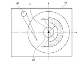
- FIG. 4 is a schematic view showing a region for measuring the thickness of the base plate (base plate member).
- FIG. 5 is an example of an image of the metal structure of the base plate taken with an optical microscope.
- FIG. 1 is a schematic view showing an example of a hard disk drive with a built-in thin substrate in this embodiment.
- the hard disk drive 1 with a built-in thin substrate in the present embodiment is inserted into a disk-shaped magnetic disk 30 having a through hole in the center and a through hole of the magnetic disk 30, and rotates the magnetic disk 30 together.
- a spindle motor 20 that can support the spindle motor 20 and a base plate 10 made of an aluminum alloy that supports the spindle motor 20 are provided.
- the HDD 1 with a built-in thin substrate rotates and rotates a magnetic head 50 that processes data on the magnetic disk 30, a swing arm 70 that movably supports the magnetic head 50 with respect to the magnetic disk 30, and a swing arm 70. It includes an actuator 40 for positioning.
- the number of magnetic disks 30 may be one or a plurality. Further, by connecting the base plate 10 to the cover plate 60, various parts such as the magnetic disk 30 are protected.
- Aluminum alloy base plate (base plate member) The metal structure of the aluminum alloy base plate (base plate member) will be described. In the following description, the configuration, characteristics, etc. of the base plate shall be similarly applied to the base plate member.
- the base plate has a metal structure having a peripheral length of 3 mm / mm 2 or more for the second phase particles having a maximum diameter of 10 ⁇ m or more.
- the impact resistance of the base plate is improved when the peripheral length of the existing second phase particles having a maximum diameter of 10 ⁇ m or more is 3 mm / mm 2 or more. It is considered that this is because the vibration energy at the time of impact is absorbed at the interface between the second phase particles and the aluminum alloy matrix.
- the impact resistance of the base plate is high, so that the impact is mitigated by the base plate and the impact transmitted to the magnetic disk is reduced.
- the impact resistance of the magnetic disk is improved, and the deformation of the magnetic disk can be suppressed.
- the peripheral length of the existing second phase particles having a maximum diameter of 10 ⁇ m or more is less than 3 mm / mm 2 , the vibration energy absorbed at the interface between the second phase particles and the aluminum alloy matrix is absorbed. Due to its small size, impact resistance does not improve. Therefore, the peripheral length of the second phase particles existing in the metal structure of the base plate is in the range of 3 mm / mm 2 or more, and preferably in the range of 5 mm / mm 2 or more.
- the upper limit of the peripheral length is not particularly limited, but it is preferably 1000 mm / mm 2 or less in consideration of the alloy component of the base plate and the like. Further, since the second phase particles having the longest diameter of less than 10 ⁇ m have almost no effect on the impact resistance, the lower limit of the longest diameter of the second phase particles is less than 10 ⁇ m.
- FIG. 2 shows the time when an impact test was performed using a base plate having a peripheral length of 3 mm / mm 2 or more and a base plate having a peripheral length of less than 3 mm / mm 2 in the second phase particles having a maximum diameter of 10 ⁇ m or more.
- the relationship with the displacement of the substrate (disk) is shown.
- the base plate containing the second phase particles having a maximum diameter of 10 ⁇ m or more having a peripheral length of 3 mm / mm 2 or more in the metal structure has a longest diameter having a peripheral length of less than 3 mm / mm 2 .
- the maximum displacement that is, the deformation of the substrate (disk) is smaller than that of the base plate containing the second phase particles of 10 ⁇ m or more in the metal structure.
- the impact resistance transmitted to the magnetic disk can be reduced by using a base plate containing the second phase particles with a maximum diameter of 10 ⁇ m or more having a peripheral length of 3 mm / mm 2 or more in the metal structure, so that the impact resistance of the magnetic disk can be reduced. Can be improved.
- the second phase particles mainly mean precipitates and crystallization of intermetallic compounds.
- Al- such as Al 3 Fe, Al 6 Fe, Al 6 (Fe, Mn), Al-Fe-Si, Al-Fe-Mn-Si, Al-Fe-Ni, Al-Cu-Fe, etc.
- Fe-based intermetallic compounds include Fe-based intermetallic compounds.
- Mg-Si-based metal-to-metal compounds Mg 2 Si, etc.
- Al-Mn-based metal-to-metal compounds Al 6 Mn, Al-Mn-Si, etc.
- Al-Ni-based metals Inter-compounds Al 3 Ni, etc.
- Al-Cu-based intermetallic compounds Al 2 Cu, etc.
- Al-Cr-based intermetallic compounds Al 7 Cr, etc.
- Al-Zr-based intermetallic compounds Al 3 Zr, etc.
- Examples thereof include intermetal compounds such as Si particles and the like as the second phase particles.
- the base plate has a metal structure in which the number of second phase particles having a maximum diameter of 500 ⁇ m or more is 0 / mm 2 .
- the base plate The thickness also tends to be thin.
- the impact resistance of the base plate is lowered, and as a result, the impact resistance of the magnetic disk is also lowered. Further, if a crack or a hole is generated in the base plate, helium or the like enclosed in the HDD may leak to the outside. Therefore, a base plate in which one or more coarse second -phase particles having a maximum diameter of 500 ⁇ m or more are present in the metal structure is unsuitable as a base plate applied to an HDD. From this point of view, it is considered that the impact resistance of the magnetic disk is improved by having 0 particles / mm 2 of the second phase particles having a maximum diameter of 500 ⁇ m or more in the metal structure of the base plate.
- the upper limit of the longest diameter of 500 ⁇ m or more is not particularly limited, but is naturally determined by the alloy components and the like, and is about 3000 ⁇ m.
- the unit piece / mm 2 of the second phase particles having a maximum diameter of 500 ⁇ m or more means the number of second phase particles having a maximum diameter of 500 ⁇ m or more existing in 1 mm 2 .
- the longest diameter of the second phase particles present in the metallographic structure of the base plate is measured from a planar image of the second phase particles A observed with an optical microscope, as shown in FIG. Specifically, as shown in FIG. 3, in the second phase particle A, first, the linear distance between one point on the contour line of the observed second phase particle A and another point on the contour line is measured. Next, this linear distance is measured for all points on the contour line, and finally, the largest diameter selected from these all linear distances is selected as the longest diameter. The largest diameter thus selected is defined as the longest diameter D max of the second phase particles. Further, the peripheral length of the second phase particle is, as shown in FIG. 3, the length L on the contour line of the intermetallic compound A observed in the plan image of the second phase particle A observed with an optical microscope.
- the unit mm / mm 2 of the perimeter means the total perimeter of all the second phase particles having a maximum diameter of 10 ⁇ m or more existing in 1 mm 2 .
- the image is taken without using a polarizing filter.
- the distinction between the second phase particles and the matrix is performed by the contrast density in the image taken by the optical microscope, and as shown in FIG. 5, those having a higher or lighter contrast than the matrix are defined as the second phase particles.
- the peripheral length and the longest diameter of the second phase particles can be calculated by SEM (scanning electron microscope).
- SEM scanning electron microscope
- the distinction between the second phase particles and the matrix is possible by the shade of contrast in the COMP image (composition image). Particles with higher or lighter contrast than the matrix are identified as Phase 2 particles.
- Hitachi Flex SEM100 scanning electron microscope, operation Ver. 1.9
- acceleration voltage 15 kv
- magnification 1000 times
- scan resolution 1024 pixels
- scan duel time 35 ⁇ s
- field of view area 0. .07 mm Perform under the condition of 2 or more.
- the peripheral length (mm / mm 2 ) and the longest diameter of the second phase particles are calculated using particle analysis software (trade name: particle analysis software A image-kun, manufactured by Asahi Kasei Engineering Co., Ltd.).
- particle analysis software trade name: particle analysis software A image-kun, manufactured by Asahi Kasei Engineering Co., Ltd.
- the perimeter and longest diameter of the second phase particles can be calculated in combination with particle analysis software.
- particle analysis software AZtec (Ver. 3.3 SPI) manufactured by Oxford is used, and the second phase particles having a higher or lighter contrast than the matrix are analyzed one by one by EDS (energy dispersive X-ray analysis). Calculate the peripheral length (mm / mm 2 ) and the longest diameter of the second phase particles.
- the analysis time by EDS for each detected second phase particle is 2 seconds.
- the base plate is made of aluminum alloy, preferably made of aluminum alloy.
- the aluminum alloy has a total content of Fe (iron), Mn (manganese) and Ni (nickel) of 0.05% by mass or more and 7.0% by mass or less, and the balance is composed of aluminum and unavoidable impurities.
- the aluminum alloy is optionally Si (silicon): 0% by mass or more and 24.0% by mass or less, Zn (zinc): 0% by mass or more and 7.0% by mass or less, Cu (copper): 0% by mass or more.
- Mg magnesium: 0% by mass or more and 3.5% by mass or less
- Be berylium: 0% by mass or more and 0.0015% by mass or less
- Cr chromium: 0% by mass or more and 0.30% by mass % Or less
- Zr zirconia: 0% by mass or more and 0.15% by mass or less
- Sr sinrontium: 0% by mass or more and 0.1% by mass or less
- Na sodium
- P phosphorus
- Fe mainly exists as second phase particles (Al-Fe-based intermetallic compound, etc.), and a part thereof is dissolved in a matrix and exists. Fe exerts the effect of improving the impact resistance of the base plate by the formation of the second phase particles and the solid solution into the matrix.
- Mn and Ni also exist mainly as second phase particles (Al—Mn-based intermetallic compound, Al—Ni-based intermetallic compound, etc.), and some of them are dissolved in the matrix and exist.
- Mn and Ni also exert the effect of improving the impact resistance of the base plate due to the formation of the second phase particles and the solid solution into the matrix.
- the total content of Fe, Mn, and Ni is less than 0.05% by mass, the formation of the second phase particles is insufficient, and the impact resistance may be lowered.
- the total content of Fe, Mn, and Ni exceeds 7.0% by mass, coarse second-phase particles may be generated and the impact resistance may be lowered. Therefore, the total content of Fe, Mn, and Ni is preferably 0.05% by mass or more and 7.0% by mass or less.
- Si mainly exists as second phase particles (Si particles or the like) and has an effect of improving the impact resistance of the base plate. Therefore, 24.0% by mass or less of Si may be arbitrarily added to the aluminum alloy. When the content of Si in the aluminum alloy is 24.0% by mass or less, the formation of coarse Si particles is suppressed. Thereby, the effect of further improving the impact resistance of the base plate can be obtained.
- the Si content is preferably 5.0% by mass or more in order to promote the formation of the second phase particles and sufficiently exert the effect of improving the impact resistance.
- Zn When the aluminum alloy contains Zn, Zn forms second phase particles with other additive elements and has the effect of improving the impact resistance of the base plate. Therefore, Zn of 7.0% by mass or less may be arbitrarily added to the aluminum alloy. When the Zn content in the aluminum alloy is 7.0% by mass or less, the formation of coarse second phase particles is suppressed. Thereby, the effect of further improving the impact resistance of the base plate can be obtained.
- Cu copper
- Al-Cu-based intermetallic compound or the like second phase particles
- 5.0% by mass or less of Cu may be optionally added to the aluminum alloy.
- the Cu content in the aluminum alloy is 5.0% by mass or less, the formation of coarse second phase particles is suppressed. Thereby, the effect of further improving the impact resistance of the base plate can be obtained.
- Mg manganesium
- Mg When the aluminum alloy contains Mg, Mg forms second phase particles with other additive elements and has the effect of improving the impact resistance of the base plate. Therefore, 3.5% by mass or less of Mg may be arbitrarily added to the aluminum alloy. When the Mg content in the aluminum alloy is 3.5% by mass or less, the formation of coarse second phase particles is suppressed. Thereby, the effect of further improving the impact resistance of the base plate can be obtained.
- the aluminum alloy contains Be
- Be preferentially oxidizes at the time of molten metal, so that it is possible to suppress the oxidation of other additive elements, that is, the other additive elements are likely to form second phase particles. Therefore, it has the effect of further improving the impact resistance of the base plate. Therefore, Be of 0.0015% by mass or less may be optionally added to the aluminum alloy. However, even if Be is contained in an amount of more than 0.0015% by mass, the effect is saturated and no further remarkable improvement effect can be obtained.
- Cr chromium
- Al—Cr-based intermetallic compound or the like a second phase particle
- Cr mainly exists as a second phase particle (Al—Cr-based intermetallic compound or the like)
- Al—Cr-based intermetallic compound or the like a second phase particle
- Cr of 0.30% by mass or less may be arbitrarily added to the aluminum alloy.
- the Cr content in the aluminum alloy is 0.30% by mass or less, the formation of coarse second phase particles is suppressed. Thereby, the effect of further improving the impact resistance of the base plate can be obtained.
- Zr mainly exists as a second phase particle (Al—Zr-based intermetallic compound or the like) and has an effect of improving the impact resistance of the base plate. Therefore, Zr of 0.15% by mass or less may be optionally added to the aluminum alloy. When the Zr content in the aluminum alloy is 0.15% by mass or less, the formation of coarse second phase particles is suppressed. Thereby, the effect of further improving the impact resistance of the base plate can be obtained.
- the aluminum alloy contains at least one of Na, Sr and P, Na, Sr and P reduce the size non-uniformity of the second phase particles (mainly Si particles) in the base plate and the impact resistance of the base plate. It has the effect of reducing the variation in aluminum. Therefore, in the aluminum alloy, one or more elements selected from the group consisting of 0.1% by mass or less of Na, 0.1% by mass or less of Sr, and 0.1% by mass or less of P are optionally contained. It may be added. However, even if each of Na, Sr and P is contained in an amount of more than 0.1% by mass, the effect is saturated and no further remarkable improvement effect can be obtained.
- Ti, B and V have the effect of reducing the size non-uniformity of the second phase particles in the base plate and reducing the variation in impact resistance of the base plate. There is. Therefore, when at least one of Ti, B and V is added, the total content of Ti, B and V is preferably in the range of 0.500% by mass or less. However, even if the total content of Ti, B and V exceeds 0.500% by mass, the effect is saturated and no further remarkable improvement effect can be obtained.
- the base plate made of an aluminum alloy may contain elements that are unavoidable impurities other than the above-mentioned components.
- these elements include Ga, Ca and the like, and if the content thereof is 0.10% by mass or less for each element and 0.30% by mass or less in total, the action and effect of the present invention are not impaired.
- the thickness of the base plate is preferably 0.5 mm or more and 2.0 mm or less. If the thickness of the base plate is less than 0.5 mm, the base plate may be deformed when dropped when the HDD is attached. Further, if the thickness of the base plate is larger than 2.0 mm, the number of magnetic disks that can be mounted in the HDD is reduced, which is not suitable. Therefore, the thickness of the base plate is preferably 0.5 mm or more and 2.0 mm or less, and more preferably 0.5 mm or more and 1.5 mm or less.
- the thickness of the base plate is arbitrary in the region on one side of the disc, that is, the region indicated by the fill, in the region surrounded by the radius r25 mm to the radius r30 mm from the center C of the disc.
- the thickness of the base plate 10 is measured at, and the measured value is defined as the thickness of the base plate 10. Since the base plate 10 in this region is thin and affects the deformation of the base plate, the above-mentioned effect can be exerted by controlling the thickness of the base plate 10 in this region.
- the thickness of the base plate 10 is measured, for example, using a micrometer.
- the base plate can be generally manufactured by a general method such as die casting or casting.
- the aluminum alloy base material as a raw material is melted, the molten metal is prepared, and then the molten metal is die-cast or cast into the shape of the base plate.
- the molten metal temperature is in the range of 550 to 700 ° C. for 0.1 to 1 hour when the molten metal is held and cast.
- the time in the range of 550 to 700 ° C. is 0.1 to 1 hour, the formation of coarse second phase particles is suppressed, and a large number of fine second phase particles are generated. Therefore, the peripheral length of the second phase particles becomes long, which has the effect of improving the impact resistance of the base plate.
- the base material of the magnetic disk is not particularly limited, but is preferably a base material made of, for example, an aluminum alloy or glass.
- the thickness of the magnetic disk is preferably 0.20 mm or more and 0.58 mm or less, and more preferably 0.48 mm or less. If the thickness of the magnetic disk is less than 0.20 mm, the magnetic disk may be deformed or cracked if the magnetic disk is dropped when the HDD is attached. On the other hand, if the thickness of the magnetic disk is larger than 0.58 mm, the impact resistance is improved, but the number of magnetic disks that can be mounted in the HDD is reduced, which is not suitable for promoting the thinning of the magnetic disk.
- the magnetic disk can be manufactured by using a magnetic disk substrate such as an aluminum alloy substrate or a glass substrate.
- an aluminum alloy substrate composed of an aluminum alloy can be used as the substrate for the magnetic disk.
- the alloy composition of the aluminum alloy substrate for a magnetic disk and the manufacturing method thereof will be described in detail.
- the aluminum alloy used for the aluminum alloy substrate for magnetic disks preferably contains elements such as Mg, Cu, Zn, and Cr. It can also contain elements such as Fe, Mn, and Ni that can improve the rigidity.
- the aluminum alloy used for the aluminum alloy substrate contains Mg, which is an essential element, in an amount of 1.0% by mass or more and 6.5% by mass or less, and optionally, Cu: 0% by mass. 0.070% by mass or less, Zn: 0% by mass or more and 0.60% by mass or less, Fe: 0% by mass or more and 0.50% by mass or less, Si: 0% by mass or more and 0.50% by mass or less, Cr: 0 Contains mass% or more and 0.20% by mass or less, Mn: 0% by mass or more and 0.50% by mass or less, Zr: 0% by mass or more and 0.20% by mass or less, Be: 0% by mass or more and 0.0020% by mass or less.
- the balance consists of aluminum and unavoidable impurities.
- the aluminum alloy used for the aluminum alloy substrate contains Fe, which is an essential element, and one or two of Mn and Ni, which are arbitrary elements, and contains Fe, Mn, and Ni.
- the total amount is 1.0% by mass or more and 7.0% by mass or less, and optionally, Si: 0% by mass or more and 14.0% by mass or less, Zn: 0% by mass or more and 0.7% by mass or less, Cu: 0% by mass or more and 1.0% by mass or less, Mg: 0% by mass or more and 4.5% by mass or less, Cr: 0% by mass or more and 0.30% by mass or less, Zr: 0% by mass or more and 0.20% by mass Below, Be: 0% by mass or more and 0.0015% by mass or less, Sr: 0% by mass or more and 0.1% by mass or less, Na: 0% by mass or more and 0.1% by mass or less, P: 0% by mass or more and 0.1. It contains less than% by mass, and the balance consists of aluminum and unavoidable
- the aluminum alloy used for the aluminum alloy substrate may contain elements that are unavoidable impurities other than the above-mentioned essential components and optional components. Examples of these elements include Ti, V, Ga and the like, and the content thereof may be 0.10% by mass or less for each element, and 0.30% by mass or less in total. Further, Si can be positively added as an optional component, but it may not be added. Si is contained as an unavoidable impurity not only in a general-purity bullion but also in a high-purity bullion having an Al purity of 99.9% or more. As described above, when Si is contained as an unavoidable impurity, the content of Si is preferably 0.10% by mass or less.
- a molten aluminum alloy material having the above-mentioned composition is prepared by heating and melting according to a conventional method.
- the prepared molten metal of the aluminum alloy material is cast by a semi-continuous casting (DC casting) method, a continuous casting (CC casting) method, or the like to cast the aluminum alloy material.
- the DC-cast aluminum alloy ingot is homogenized as necessary.
- the aluminum alloy ingot (DC casting) that has been homogenized or has not been homogenized is hot-rolled to obtain a plate material.
- the hot-rolled rolled plate or the cast plate cast by the CC casting method is cold-rolled to obtain an aluminum alloy plate. Annealing may be performed to ensure cold rolling workability before or during cold rolling.
- the aluminum alloy plate obtained by cold rolling is punched into an annular shape to obtain an annular aluminum alloy plate.
- the annular aluminum alloy plate becomes a disc blank by the pressure flattening treatment.
- the disc blank is subjected to cutting / grinding and, if necessary, heat treatment before ginkating.
- the surface of the disc blank is degreased and etched, and a zincate treatment (Zn replacement treatment) is performed.
- Zn replacement treatment zincate treatment
- a zincate film is formed on the surface of the disk blank.
- an electroless Ni-P plating treatment is applied to the surface of the zincated disc blank as a base treatment for adhering a magnetic substance.
- the plated surface after the electroless Ni-P plating treatment is polished for smoothing. In this way, the aluminum substrate for a magnetic disk is manufactured by surface polishing after the plating treatment.
- Glass substrate for magnetic disk As the magnetic disk substrate, for example, a glass substrate made of a glass material can also be used. Hereinafter, the applied glass material and the method for manufacturing the glass substrate will be described in detail with respect to the glass substrate for a magnetic disk.
- the glass used for the substrate for a magnetic disk contains SiO 2 of 55% by mass or more and 75% by mass or less as a main component, and further, Al 2O 3 : 0.7% by mass or more and 25% by mass or less, Li 2O : 0.
- Such glasses include B 2 O 3 (aluminoborosilicate glass, contained as an essential ingredient in borosilicate glass), which lowers viscosity and enhances solubility and clarity, reduces high temperature viscosity, and dissolves and clarifies.
- SrO, BaO which improves the properties and moldability and shows the effect of improving the young rate
- ZnO which improves the ion exchange performance and lowers the high temperature viscosity without lowering the low temperature viscosity, improves the clarity and ion exchange performance.
- a colorant Fe 2 O 3 and the like, As 2 O 3 and Sb 2 O 3 may be further contained as a clarifying agent.
- oxides such as La, P, Ce, Sb, Hf, Rb and Y may be contained.
- the glass material prepared in a predetermined chemical composition is melted, and the molten mass is press-molded from both sides by a direct press method to prepare a glass base plate having a desired thickness.
- the production of the glass base plate is not limited to the direct press method, and may be a float method, a fusion method, a redraw method, or the like.
- this glass base plate is cored in an annular shape, and the inner diameter portion and the outer diameter portion are further polished to obtain an annular glass plate having a desired inner diameter dimension, outer diameter dimension, and chamfer length.
- the surfaces of both surfaces of the annular glass plate are ground by a grinding machine (hereinafter referred to as lapping process) to obtain an annular glass substrate having a desired plate thickness and flatness. Further, the surfaces of both surfaces of the annular glass substrate are polished with a polishing machine to produce a disk having a desired thickness, that is, a glass substrate. During the polishing process, a chemical strengthening treatment with a sodium nitrate solution, a potassium nitrate solution, or the like may be performed. In this way, the glass substrate for a magnetic disk is manufactured by surface polishing.
- the magnetic disk may further have a magnetic material layer laminated on these substrates. Further, it may have a protective layer made of a carbon-based material such as diamond-like carbon and laminated on a magnetic material layer, and a lubricating layer made of a lubricating oil and coated on the protective layer.
- the present invention is not limited to the above embodiment, and various types are based on the technical idea of the present invention. Can be modified and changed.
- molten metal having the chemical components shown in Table 1 was prepared in the melting furnace / holding furnace. Next, the molten metal in the melting furnace / holding furnace was supplied to the mold to prepare a base plate member (test material) having a thickness of 1.5 mm. Table 1 shows the time when the molten metal temperature is in the range of 550 to 700 ° C.
- the surface was polished at the site and measurement was performed.
- the peripheral length of the second phase particles having a maximum diameter of 10 ⁇ m or more exposed on the surface of the test material is 3 mm / mm 2 or more, and the maximum diameter is 500 ⁇ m or more.
- the number of second phase particles was 0 / mm 2 .
- FIG. 2 in the metal structure of the base plate, if the peripheral length of the second phase particles having a maximum diameter of 10 ⁇ m or more is 3 mm / mm 2 or more, it can be evaluated that the impact transmitted to the magnetic disk can be reduced. Therefore, by quoting FIG. 2, it can be evaluated that these test materials can enhance the impact resistance of the magnetic disk.
- the molten metal temperature was in the range of 550 to 700 ° C. for 1.5 hours, and many second phase particles having a maximum diameter of 500 ⁇ m or more were generated. Therefore, the number of second phase particles having a maximum diameter of 500 ⁇ m or more is 1 / mm 2 , and the test material is not suitable as a base plate member.
- the test material of Comparative Example 2 the peripheral length of the second phase particles was 1.6 mm / mm 2 , which was too short. Therefore, referring to FIG. 2, the test material is each of Examples 1 to 4. It can be evaluated that the impact resistance characteristics are inferior to those of the base plate member made from the test material.
- Base plate 20 Spindle motor 30
Landscapes
- Chemical & Material Sciences (AREA)
- Engineering & Computer Science (AREA)
- Materials Engineering (AREA)
- Mechanical Engineering (AREA)
- Metallurgy (AREA)
- Organic Chemistry (AREA)
- Magnetic Record Carriers (AREA)
- Manufacturing Of Magnetic Record Carriers (AREA)
Abstract
本発明に係る薄型基板内蔵ハードディスクドライブ(1)は、中央部に貫通孔を有する円盤形状の磁気ディスク(30)と、磁気ディスク(30)の貫通孔に挿入され、磁気ディスク(30)を共回転可能に支持するスピンドルモータ(20)と、スピンドルモータ(20)を支持するアルミニウム合金製のベースプレート(10)と、を備える。ベースプレート(10)が、最長径10μm以上の第2相粒子の周囲長が3mm/mm2以上であり、かつ最長径500μm以上の第2相粒子が0個/mm2である金属組織を有する。
Description
本発明は、薄型基板内蔵ハードディスクドライブ及び薄型基板内蔵ハードディスクドライブ用ベースプレート部材に関する。
近年、コンピュータの記録装置としてハードディスクドライブ(以下「HDD」ともいう)が広く用いられている。HDDには、記録媒体用のディスクを支持及び回転させる磁気ディスク駆動装置が搭載されており、磁気ディスク駆動装置は、一般に、データを記録する1枚又は複数枚の磁気ディスク、磁気ディスクを回転させるスピンドルモータ、及び磁気ディスクの内径側部分を固定するクランプ部材を有している。HDDには、このような磁気ディスク駆動装置の他に、各磁気ディスクに対してデータ処理を行う磁気ヘッド、当該磁気ヘッドを磁気ディスクに対して移動自在に支持したアクチュエータ、当該アクチュエータを回動及び位置決めするスイングアーム等が備えられている。
ところで、近年になって、HDDには、マルチメディア等のニーズから大容量化及び密度化が求められている。また、更なる大容量化のため、記憶装置に搭載される磁気ディスクの枚数が増加しており、それに伴い磁気ディスクの薄肉化も求められている。しかしながら、磁気ディスクを薄肉化すると剛性が低下してしまう問題がある。剛性が低下すると、磁気ディスクが変形し難い程度を示す耐衝撃性が低下してしまうため、耐衝撃性の向上が求められている。
このような実情から、近年では高い剛性を有する磁気ディスクが強く望まれ、検討されている。例えば、特許文献1では、磁気ディスク用アルミニウム合金基板に剛性向上に寄与するSiを多く含有させて、耐衝撃性を向上させる方法が提案されている。
しかしながら、Siの含有量を増やして剛性を向上させる特許文献1に開示の方法は、耐衝撃性の向上には有効であるものの、製造性との兼ね合いから添加できるSi量には限りがあり、目標とする良好な耐衝撃性は得られていないのが現状であった。
本発明は、かかる実情に鑑みてなされたものであり、耐衝撃性に優れる、薄型基板内蔵ハードディスクドライブ及び薄型基板内蔵ハードディスクドライブ用ベースプレート部材を提供するものである。
本発明者らは、上記問題に対して鋭意検討を行った結果、薄型基板内蔵ハードディスクドライブにおける磁気ディスクとベースプレートとの相関性を明らかにすることにより、磁気ディスクの耐衝撃性を向上することができる薄型基板内蔵ハードディスクドライブ及び薄型基板内蔵ハードディスクドライブ用ベースプレート部材を提供できることを見出した。
本発明の一態様は、中央部に貫通孔を有する円盤形状の磁気ディスクと、前記磁気ディスクの貫通孔に挿入され、前記磁気ディスクを共回転可能に支持するスピンドルモータと、当該スピンドルモータを支持するアルミニウム合金製のベースプレートと、を備え、前記ベースプレートが、最長径10μm以上の第2相粒子の周囲長が3mm/mm2以上であり、かつ最長径500μm以上の第2相粒子が0個/mm2である金属組織を有する薄型基板内蔵ハードディスクドライブである。
本発明の他の態様は、最長径10μm以上の第2相粒子の周囲長が3mm/mm2以上であり、かつ最長径500μm以上の第2相粒子が0個/mm2である金属組織を有するアルミニウム合金製の薄型基板内蔵ハードディスクドライブ用ベースプレート部材である。
本発明によれば、中央部に貫通孔を有する円盤形状の磁気ディスクと、前記磁気ディスクの貫通孔に挿入され、前記磁気ディスクを共回転可能に支持するスピンドルモータと、当該スピンドルモータを支持するアルミニウム合金製のベースプレートと、を備える薄型基板内蔵ハードディスクドライブにおいて、前記ベースプレートが、最長径10μm以上の第2相粒子の周囲長が3mm/mm2以上であり、かつ最長径500μm以上の第2相粒子が0個/mm2である金属組織を有することにより、磁気ディスクの耐衝撃性を向上することができる薄型基板内蔵ハードディスクドライブを提供することができる。
また、アルミニウム合金製の薄型基板内蔵ハードディスクドライブ用ベースプレート部材が、最長径10μm以上の第2相粒子の周囲長が3mm/mm2以上であり、かつ最長径500μm以上の第2相粒子が0個/mm2である金属組織を有することにより、磁気ディスクの耐衝撃性を向上することができる薄型基板内蔵ハードディスクドライブ用ベースプレート部材を提供することができる。
以下、本実施形態における薄型基板内蔵ハードディスクドライブ及び薄型基板内蔵ハードディスクドライブ用ベースプレート部材について図面を参照しながら説明する。
図1は、本実施形態における薄型基板内蔵ハードディスクドライブの一例を示す概略図である。図1に示すように、本実施形態における薄型基板内蔵ハードディスクドライブ1は、中央部に貫通孔を有する円盤形状の磁気ディスク30と、磁気ディスク30の貫通孔に挿入され、磁気ディスク30を共回転可能に支持するスピンドルモータ20と、スピンドルモータ20を支持するアルミニウム合金製のベースプレート10と、を備える。更に、薄型基板内蔵HDD1は、磁気ディスク30に対してデータ処理を行う磁気ヘッド50と、磁気ヘッド50を磁気ディスク30に対して移動自在に支持するスイングアーム70と、スイングアーム70を回動及び位置決めするアクチュエータ40と、を備えている。磁気ディスク30は1枚であってもよく、複数枚であってもよい。また、ベースプレート10がカバープレート60と結合されることにより、磁気ディスク30等の各種部品が保護される。
A.アルミニウム合金製のベースプレート(ベースプレート部材)
アルミニウム合金製のベースプレート(ベースプレート部材)が有する金属組織について説明する。尚、以下の説明において、ベースプレートの構成、特性等はベースプレート部材にも同様に適用されるものとする。
アルミニウム合金製のベースプレート(ベースプレート部材)が有する金属組織について説明する。尚、以下の説明において、ベースプレートの構成、特性等はベースプレート部材にも同様に適用されるものとする。
(最長径10μm以上の第2相粒子の周囲長)
アルミニウム合金製のベースプレートの金属組織中には、第2相粒子として、金属間化合物や粒子等が存在する。具体的には、ベースプレートは、最長径10μm以上の第2相粒子の周囲長が3mm/mm2以上である金属組織を有する。ベースプレートの金属組織において、存在する最長径10μm以上の第2相粒子の周囲長が3mm/mm2以上であることにより、ベースプレートの耐衝撃性が向上する。これは、第2相粒子とアルミニウム合金マトリックスの界面で衝撃時の振動エネルギー等が吸収されること等が考えられる。これにより、HDD落下時等のHDDに衝撃が加わったときに、ベースプレートの耐衝撃性が高いため、ベースプレートで衝撃が緩和され、磁気ディスクに伝わる衝撃が小さくなる。その結果、磁気ディスクの耐衝撃性が向上し、磁気ディスクの変形を抑制できる。
アルミニウム合金製のベースプレートの金属組織中には、第2相粒子として、金属間化合物や粒子等が存在する。具体的には、ベースプレートは、最長径10μm以上の第2相粒子の周囲長が3mm/mm2以上である金属組織を有する。ベースプレートの金属組織において、存在する最長径10μm以上の第2相粒子の周囲長が3mm/mm2以上であることにより、ベースプレートの耐衝撃性が向上する。これは、第2相粒子とアルミニウム合金マトリックスの界面で衝撃時の振動エネルギー等が吸収されること等が考えられる。これにより、HDD落下時等のHDDに衝撃が加わったときに、ベースプレートの耐衝撃性が高いため、ベースプレートで衝撃が緩和され、磁気ディスクに伝わる衝撃が小さくなる。その結果、磁気ディスクの耐衝撃性が向上し、磁気ディスクの変形を抑制できる。
一方、ベースプレートの金属組織において、存在する最長径10μm以上の第2相粒子の周囲長が3mm/mm2未満である場合、第2相粒子とアルミニウム合金マトリックスとの界面で吸収される振動エネルギーが小さいため、耐衝撃性が向上しない。そのため、ベースプレートの金属組織中に存在する第2相粒子の周囲長は3mm/mm2以上の範囲であり、5mm/mm2以上の範囲であることが好ましい。尚、周囲長の上限は特に限定されるものではないが、ベースプレートの合金成分等を勘案して、1000mm/mm2以下であることが好ましい。また、最長径10μm未満の第2相粒子は耐衝撃性にほとんど影響を及ぼさないため、第2相粒子の最長径の下限は10μm未満である。
図2は、最長径10μm以上の第2相粒子において、周囲長が3mm/mm2以上であるベースプレートと周囲長が3mm/mm2未満のベースプレートとを用いて衝撃試験を行った際の時間と基板(ディスク)変位との関係を示す。図2に示されるように、周囲長が3mm/mm2以上である最長径10μm以上の第2相粒子を金属組織中に含むベースプレートの方が、周囲長が3mm/mm2未満である最長径10μm以上の第2相粒子を金属組織中に含むベースプレートよりも、基板(ディスク)の最大変位、即ち、変形が小さいことがわかる。このことから、周囲長が3mm/mm2以上である最長径10μm以上の第2相粒子を金属組織中に含むベースプレートの使用により、磁気ディスクに伝わる衝撃を小さくできるため、磁気ディスクの耐衝撃性を向上させることができる。
第2相粒子とは、主に金属間化合物の析出物や晶出物等を意味する。具体的には、Al3Fe、Al6Fe、Al6(Fe、Mn)、Al-Fe-Si、Al-Fe-Mn-Si、Al-Fe-Ni、Al-Cu-Fe等のAl-Fe系金属間化合物が挙げられる。Al-Fe系金属間化合物の他に、Mg-Si系金属間化合物(Mg2Si等)、Al-Mn系金属間化合物(Al6Mn、Al-Mn-Si等)、Al-Ni系金属間化合物(Al3Ni等)、Al-Cu系金属間化合物(Al2Cu等)、Al-Cr系金属間化合物(Al7Cr等)、Al-Zr系金属間化合物(Al3Zr等)等の金属間化合物が挙げられ、第2相粒子にはSi粒子等も含まれる。
(最長径500μm以上の第2相粒子)
ベースプレートは、最長径500μm以上の第2相粒子が0個/mm2である金属組織を有する。上述の通り、HDDの大容量化のため、磁気ディスクの厚さを薄くし、ディスクの搭載枚数を増加させていることが検討されているが、磁気ディスクの搭載枚数を増加させるため、ベースプレートの厚さも薄くなる傾向にある。ベースプレートの厚さが薄い場合、ベースプレートの金属組織中に粗大な第2相粒子(500μm以上)が存在すると、そこを起点に亀裂や穴が発生する恐れがある。その場合、ベースプレートの耐衝撃性が低下し、その結果、磁気ディスクの耐衝撃性の低下にも繋がると考えられる。また、ベースプレートに亀裂や穴が発生した場合、HDDの中に封入されるヘリウム等が外に漏れだす可能性もある。そのため、金属組織中に最長径500μm以上の粗大な第2相粒子が1個/mm2以上存在するベースプレートは、HDDに適用するベースプレートとしては不適格である。このような観点から、ベースプレートの金属組織において、最長径500μm以上の第2相粒子が0個/mm2であることで、磁気ディスクの耐衝撃性が向上すると考えられる。尚、500μm以上の最長径の上限は特に限定されるものではないが、合金成分等により自ずと決まり、3000μm程度である。尚、最長径500μm以上の第2相粒子の単位個/mm2は、1mm2に存在する最長径500μm以上の第2相粒子の個数を意味する。
ベースプレートは、最長径500μm以上の第2相粒子が0個/mm2である金属組織を有する。上述の通り、HDDの大容量化のため、磁気ディスクの厚さを薄くし、ディスクの搭載枚数を増加させていることが検討されているが、磁気ディスクの搭載枚数を増加させるため、ベースプレートの厚さも薄くなる傾向にある。ベースプレートの厚さが薄い場合、ベースプレートの金属組織中に粗大な第2相粒子(500μm以上)が存在すると、そこを起点に亀裂や穴が発生する恐れがある。その場合、ベースプレートの耐衝撃性が低下し、その結果、磁気ディスクの耐衝撃性の低下にも繋がると考えられる。また、ベースプレートに亀裂や穴が発生した場合、HDDの中に封入されるヘリウム等が外に漏れだす可能性もある。そのため、金属組織中に最長径500μm以上の粗大な第2相粒子が1個/mm2以上存在するベースプレートは、HDDに適用するベースプレートとしては不適格である。このような観点から、ベースプレートの金属組織において、最長径500μm以上の第2相粒子が0個/mm2であることで、磁気ディスクの耐衝撃性が向上すると考えられる。尚、500μm以上の最長径の上限は特に限定されるものではないが、合金成分等により自ずと決まり、3000μm程度である。尚、最長径500μm以上の第2相粒子の単位個/mm2は、1mm2に存在する最長径500μm以上の第2相粒子の個数を意味する。
ベースプレートの金属組織中に存在する第2相粒子の最長径は、図3に示されるように、光学顕微鏡で観察される第2相粒子Aの平面画像から計測される。具体的には、図3に示されるように、第2相粒子Aにおいて、まず、観察された第2相粒子Aの輪郭線上における一点と輪郭線上の他の点との直線距離を計測する。次に、この直線距離を輪郭線上における全ての点について計測し、最後に、これら全直線距離のうちから選択される最も大きな径を最長径として選択する。こうして選択された最も大きな径を第2相粒子の最長径Dmaxとして定義する。また、第2相粒子の周囲長とは、図3に示されるように、光学顕微鏡で観察される第2相粒子Aの平面画像において、観察された金属間化合物Aの輪郭線上の長さLsを意味する。尚、周囲長の単位mm/mm2は、1mm2に存在する最長径10μm以上の第2相粒子全ての周囲長の合計を意味する。尚、光学顕微鏡による観察では、偏光フィルターを用いず撮影を行う。第2相粒子とマトリックスの区別は、光学顕微鏡で撮影した画像におけるコントラストの濃淡により行い、図5に示す通り、マトリックスよりもコントラストが濃い又は淡いものを第2相粒子とする。
光学顕微鏡による観察以外に、SEM(走査電子顕微鏡)でも第2相粒子の周囲長や最長径を算出することができる。SEMの場合、第2相粒子とマトリックスの区別は、COMP像(組成像)におけるコントラストの濃淡により可能である。マトリックスよりもコントラストが濃い又は淡いものを第2相粒子として識別している。SEM観察は、日立製FlexSEM100(走査電子顕微鏡、オペレーションVer.1.9)を用い、加速電圧:15kv、倍率:1000倍、スキャンの解像度:1024ピクセル、スキャンのデュエルタイム:35μs、視野面積:0.07mm2以上の条件にて行う。その後、粒子解析ソフト(商品名:粒子解析ソフトA像くん、旭化成エンジニアリング社製)を用いて第2相粒子の周囲長(mm/mm2)及び最長径を算出する。SEMを使用する場合、粒子解析ソフトと組み合わせて第2相粒子の周囲長や最長径を算出することができる。粒子解析ソフトはOxford社製AZtec(Ver.3.3 SPI)を用い、マトリックスよりもコントラストが濃い又は淡い第2相粒子を1つずつEDS(エネルギー分散型X線分析)にて分析を行い、第2相粒子の周囲長(mm/mm2)及び最長径を算出する。検出した第2相粒子1つあたりのEDSによる分析時間は2秒とする。
ベースプレートはアルミニウム合金で形成され、好ましくはアルミニウム合金からなる。アルミニウム合金は、Fe(鉄)とMn(マンガン)とNi(ニッケル)の含有量の合計が、0.05質量%以上7.0質量%以下であり、残部がアルミニウムと不可避不純物からなる。アルミニウム合金は、任意に、Si(ケイ素):0質量%以上24.0質量%以下、Zn(亜鉛):0質量%以上7.0質量%以下、Cu(銅):0質量%以上5.0質量%以下、Mg(マグネシウム):0質量%以上3.5質量%以下、Be(ベリリウム):0質量%以上0.0015質量%以下、Cr(クロム):0質量%以上0.30質量%以下、Zr(ジルコニア):0質量%以上0.15質量%以下、Sr(ストロンチウム):0質量%以上0.1質量%以下、Na(ナトリウム):0質量%以上0.1質量%以下、及びP(リン):0質量%以上0.1質量%以下を更に含有していてもよく、好ましくは、Ti(チタン)、B(ホウ素)及びV(バナジウム)の含有量の合計が、0質量%以上0.500質量%以下である。
(鉄、マンガン、ニッケル)
Feは、主として第2相粒子(Al-Fe系金属間化合物等)として存在すると共に、一部はマトリックスに固溶して存在する。第2相粒子の生成とマトリックスへの固溶により、Feはベースプレートの耐衝撃性を向上させる効果を発揮する。Mn及びNiも、主として第2相粒子(Al-Mn系金属間化合物、Al-Ni系金属間化合物等)として存在すると共に、一部はマトリックスに固溶して存在する。第2相粒子の生成とマトリックスへの固溶により、Mn及びNiもベースプレートの耐衝撃性を向上させる効果を発揮する。しかしながら、FeとMnとNiの含有量の合計が0.05質量%未満である場合、第2相粒子の形成が不十分であり、耐衝撃性が低下してしまうおそれがある。一方、FeとMnとNiの含有量の合計が7.0質量%を超えると、粗大な第2相粒子が生成して、耐衝撃性が低下するおそれがある。従って、FeとMnとNiの含有量の合計は0.05質量%以上7.0質量%以下であることが好ましい。
Feは、主として第2相粒子(Al-Fe系金属間化合物等)として存在すると共に、一部はマトリックスに固溶して存在する。第2相粒子の生成とマトリックスへの固溶により、Feはベースプレートの耐衝撃性を向上させる効果を発揮する。Mn及びNiも、主として第2相粒子(Al-Mn系金属間化合物、Al-Ni系金属間化合物等)として存在すると共に、一部はマトリックスに固溶して存在する。第2相粒子の生成とマトリックスへの固溶により、Mn及びNiもベースプレートの耐衝撃性を向上させる効果を発揮する。しかしながら、FeとMnとNiの含有量の合計が0.05質量%未満である場合、第2相粒子の形成が不十分であり、耐衝撃性が低下してしまうおそれがある。一方、FeとMnとNiの含有量の合計が7.0質量%を超えると、粗大な第2相粒子が生成して、耐衝撃性が低下するおそれがある。従って、FeとMnとNiの含有量の合計は0.05質量%以上7.0質量%以下であることが好ましい。
(ケイ素)
アルミニウム合金がSiを含む場合、Siは、主として第2相粒子(Si粒子等)として存在し、ベースプレートの耐衝撃性を向上させる効果がある。そのため、アルミニウム合金中に、24.0質量%以下のSiが任意に添加されてもよい。アルミニウム合金中のSiの含有量が24.0質量%以下であることによって、粗大なSi粒子が生成することを抑制する。これにより、ベースプレートの耐衝撃性を一層向上させる効果を得ることができる。アルミニウム合金がSiを含む場合、第2相粒子の形成を促進させ、耐衝撃性の向上作用を十分に発揮させるため、Siの含有量は5.0質量%以上であることが好ましい。
アルミニウム合金がSiを含む場合、Siは、主として第2相粒子(Si粒子等)として存在し、ベースプレートの耐衝撃性を向上させる効果がある。そのため、アルミニウム合金中に、24.0質量%以下のSiが任意に添加されてもよい。アルミニウム合金中のSiの含有量が24.0質量%以下であることによって、粗大なSi粒子が生成することを抑制する。これにより、ベースプレートの耐衝撃性を一層向上させる効果を得ることができる。アルミニウム合金がSiを含む場合、第2相粒子の形成を促進させ、耐衝撃性の向上作用を十分に発揮させるため、Siの含有量は5.0質量%以上であることが好ましい。
(亜鉛)
アルミニウム合金がZnを含む場合、Znは、他の添加元素と第2相粒子を形成し、ベースプレートの耐衝撃性を向上させる効果がある。そのため、アルミニウム合金中に、7.0質量%以下のZnが任意に添加されてもよい。アルミニウム合金中のZnの含有量が7.0質量%以下であることによって、粗大な第2相粒子が生成することを抑制する。これにより、ベースプレートの耐衝撃性を一層向上させる効果を得ることができる。
アルミニウム合金がZnを含む場合、Znは、他の添加元素と第2相粒子を形成し、ベースプレートの耐衝撃性を向上させる効果がある。そのため、アルミニウム合金中に、7.0質量%以下のZnが任意に添加されてもよい。アルミニウム合金中のZnの含有量が7.0質量%以下であることによって、粗大な第2相粒子が生成することを抑制する。これにより、ベースプレートの耐衝撃性を一層向上させる効果を得ることができる。
(銅)
アルミニウム合金がCuを含む場合、Cuは、主として第2相粒子(Al-Cu系金属間化合物等)として存在し、ベースプレートの耐衝撃性を向上させる効果がある。そのため、アルミニウム合金中に、5.0質量%以下のCuが任意に添加されてもよい。アルミニウム合金中のCuの含有量が5.0質量%以下であることによって、粗大な第2相粒子が生成することを抑制する。これにより、ベースプレートの耐衝撃性を一層向上させる効果を得ることができる。
アルミニウム合金がCuを含む場合、Cuは、主として第2相粒子(Al-Cu系金属間化合物等)として存在し、ベースプレートの耐衝撃性を向上させる効果がある。そのため、アルミニウム合金中に、5.0質量%以下のCuが任意に添加されてもよい。アルミニウム合金中のCuの含有量が5.0質量%以下であることによって、粗大な第2相粒子が生成することを抑制する。これにより、ベースプレートの耐衝撃性を一層向上させる効果を得ることができる。
(マグネシウム)
アルミニウム合金がMgを含む場合、Mgは、他の添加元素と第2相粒子を形成し、ベースプレートの耐衝撃性を向上させる効果がある。そのため、アルミニウム合金中に、3.5質量%以下のMgが任意に添加されてもよい。アルミニウム合金中のMgの含有量が3.5質量%以下であることによって、粗大な第2相粒子が生成することを抑制する。これにより、ベースプレートの耐衝撃性を一層向上させる効果を得ることができる。
アルミニウム合金がMgを含む場合、Mgは、他の添加元素と第2相粒子を形成し、ベースプレートの耐衝撃性を向上させる効果がある。そのため、アルミニウム合金中に、3.5質量%以下のMgが任意に添加されてもよい。アルミニウム合金中のMgの含有量が3.5質量%以下であることによって、粗大な第2相粒子が生成することを抑制する。これにより、ベースプレートの耐衝撃性を一層向上させる効果を得ることができる。
(ベリリウム)
アルミニウム合金がBeを含む場合、Beは、溶湯時において優先的に酸化するため、他の添加元素の酸化を抑制することが可能、即ち、他の添加元素が第2相粒子を形成しやすくなるため、ベースプレートの耐衝撃性を一層向上させる効果がある。そのため、アルミニウム合金中に、0.0015質量%以下のBeが任意に添加されてもよい。但し、Beが0.0015質量%を超過して含まれていてもその効果は飽和し、それ以上の顕著な改善効果が得られない。
アルミニウム合金がBeを含む場合、Beは、溶湯時において優先的に酸化するため、他の添加元素の酸化を抑制することが可能、即ち、他の添加元素が第2相粒子を形成しやすくなるため、ベースプレートの耐衝撃性を一層向上させる効果がある。そのため、アルミニウム合金中に、0.0015質量%以下のBeが任意に添加されてもよい。但し、Beが0.0015質量%を超過して含まれていてもその効果は飽和し、それ以上の顕著な改善効果が得られない。
(クロム)
アルミニウム合金がCrを含む場合、Crは、主として第2相粒子(Al-Cr系金属間化合物等)として存在し、ベースプレートの耐衝撃性を向上させる効果がある。そのため、アルミニウム合金中に、0.30質量%以下のCrが任意に添加されてもよい。アルミニウム合金中のCrの含有量が0.30質量%以下であることによって、粗大な第2相粒子が生成することを抑制する。これにより、ベースプレートの耐衝撃性を一層向上させる効果を得ることができる。
アルミニウム合金がCrを含む場合、Crは、主として第2相粒子(Al-Cr系金属間化合物等)として存在し、ベースプレートの耐衝撃性を向上させる効果がある。そのため、アルミニウム合金中に、0.30質量%以下のCrが任意に添加されてもよい。アルミニウム合金中のCrの含有量が0.30質量%以下であることによって、粗大な第2相粒子が生成することを抑制する。これにより、ベースプレートの耐衝撃性を一層向上させる効果を得ることができる。
(ジルコニウム)
アルミニウム合金がZrを含む場合、Zrは、主として第2相粒子(Al-Zr系金属間化合物等)として存在し、ベースプレートの耐衝撃性を向上させる効果がある。そのため、アルミニウム合金中に、0.15質量%以下のZrが任意に添加されてもよい。アルミニウム合金中のZrの含有量が0.15質量%以下であることによって、粗大な第2相粒子が生成することを抑制する。これにより、ベースプレートの耐衝撃性を一層向上させる効果を得ることができる。
アルミニウム合金がZrを含む場合、Zrは、主として第2相粒子(Al-Zr系金属間化合物等)として存在し、ベースプレートの耐衝撃性を向上させる効果がある。そのため、アルミニウム合金中に、0.15質量%以下のZrが任意に添加されてもよい。アルミニウム合金中のZrの含有量が0.15質量%以下であることによって、粗大な第2相粒子が生成することを抑制する。これにより、ベースプレートの耐衝撃性を一層向上させる効果を得ることができる。
(ナトリウム、ストロンチウム、リン)
アルミニウム合金がNa、Sr及びPの少なくとも一種を含む場合、Na、Sr及びPは、ベースプレート中の第2相粒子(主にSi粒子)のサイズの不均一性を小さくし、ベースプレートの耐衝撃性のバラつきを低減させる効果がある。そのため、アルミニウム合金中に、0.1質量%以下のNa、0.1質量%以下のSr、及び0.1質量%以下のPからなる群から選択された1又は2以上の元素が任意に添加されてもよい。但し、Na、Sr及びPのそれぞれが0.1質量%を超過して含まれていてもその効果は飽和し、それ以上の顕著な改善効果が得られない。
アルミニウム合金がNa、Sr及びPの少なくとも一種を含む場合、Na、Sr及びPは、ベースプレート中の第2相粒子(主にSi粒子)のサイズの不均一性を小さくし、ベースプレートの耐衝撃性のバラつきを低減させる効果がある。そのため、アルミニウム合金中に、0.1質量%以下のNa、0.1質量%以下のSr、及び0.1質量%以下のPからなる群から選択された1又は2以上の元素が任意に添加されてもよい。但し、Na、Sr及びPのそれぞれが0.1質量%を超過して含まれていてもその効果は飽和し、それ以上の顕著な改善効果が得られない。
(チタン、ホウ素、バナジウム)
アルミニウム合金がTi、B及びVの少なくとも一種を含む場合、Ti、B及びVは、ベースプレート中の第2相粒子のサイズの不均一性を小さくし、ベースプレートの耐衝撃性のバラつきを低減させる効果がある。そのため、Ti、B及びVの少なくとも一種を添加する場合、Ti、B及びVの含有量の合計は、0.500質量%以下の範囲が好ましい。但し、Ti、B及びVの含有量の合計が、0.500質量%を超過して含まれていてもその効果は飽和し、それ以上の顕著な改善効果が得られない。
アルミニウム合金がTi、B及びVの少なくとも一種を含む場合、Ti、B及びVは、ベースプレート中の第2相粒子のサイズの不均一性を小さくし、ベースプレートの耐衝撃性のバラつきを低減させる効果がある。そのため、Ti、B及びVの少なくとも一種を添加する場合、Ti、B及びVの含有量の合計は、0.500質量%以下の範囲が好ましい。但し、Ti、B及びVの含有量の合計が、0.500質量%を超過して含まれていてもその効果は飽和し、それ以上の顕著な改善効果が得られない。
(不可避不純物等のその他の元素)
アルミニウム合金製のベースプレートは、前述した成分以外の不可避的不純物となる元素が含まれていてもよい。これらの元素としては、Ga、Ca等が挙げられ、その含有量は、各元素について0.10質量%以下、合計で0.30質量%以下であれば本発明の作用効果を損なわない。
アルミニウム合金製のベースプレートは、前述した成分以外の不可避的不純物となる元素が含まれていてもよい。これらの元素としては、Ga、Ca等が挙げられ、その含有量は、各元素について0.10質量%以下、合計で0.30質量%以下であれば本発明の作用効果を損なわない。
(ベースプレートの厚さ)
ベースプレートの厚さは0.5mm以上2.0mm以下であることが好ましい。ベースプレートの厚さが0.5mm未満であると、HDDの取り付け時などに落下させた際にベースプレートが変形するおそれがある。また、ベースプレートの厚さが2.0mmより大きいとHDD内に搭載できる磁気ディスク枚数が減ってしまうため好適ではない。そのため、ベースプレートの厚さは好ましくは0.5mm以上2.0mm以下であり、より好ましくは、0.5mm以上1.5mm以下である。
ベースプレートの厚さは0.5mm以上2.0mm以下であることが好ましい。ベースプレートの厚さが0.5mm未満であると、HDDの取り付け時などに落下させた際にベースプレートが変形するおそれがある。また、ベースプレートの厚さが2.0mmより大きいとHDD内に搭載できる磁気ディスク枚数が減ってしまうため好適ではない。そのため、ベースプレートの厚さは好ましくは0.5mm以上2.0mm以下であり、より好ましくは、0.5mm以上1.5mm以下である。
ベースプレートの厚さは、図4に示されるように、ディスクの中心Cから半径r25mm~半径r30mmで囲まれる領域のうち、ディスクの片面側の領域、すなわち、塗りつぶしで示される領域において、任意の箇所にてベースプレート10の厚さを測定し、その測定値をベースプレート10の厚さとして定義する。この領域におけるベースプレート10は、厚さが薄くベースプレートの変形に影響を与えるため、この領域におけるベースプレート10の厚さを制御することにより上述の作用を発揮し得る。ベースプレート10の厚さは、例えば、マイクロメータを用いて測定される。
B.アルミニウム合金製のベースプレートの製造方法
ベースプレートは、一般的にダイキャストや鋳造等の一般的な方法により製造することができる。ベースプレートを作製する際、原料となるアルミニウム合金基材を溶解し、溶湯を作製してから溶湯をダイキャストや鋳造によってベースプレートの形状とする。溶湯を作製・鋳造する工程において、溶湯を保持・鋳造する際に溶湯温度が550~700℃の範囲にある時間が0.1~1時間であることが好ましい。550~700℃の範囲にある時間が0.1~1時間であることで、粗大な第2相粒子の生成を抑制し、微細な第2相粒子が多数生成する。そのため、第2相粒子の周囲長が長くなり、ベースプレートの耐衝撃性を向上させる効果がある。
ベースプレートは、一般的にダイキャストや鋳造等の一般的な方法により製造することができる。ベースプレートを作製する際、原料となるアルミニウム合金基材を溶解し、溶湯を作製してから溶湯をダイキャストや鋳造によってベースプレートの形状とする。溶湯を作製・鋳造する工程において、溶湯を保持・鋳造する際に溶湯温度が550~700℃の範囲にある時間が0.1~1時間であることが好ましい。550~700℃の範囲にある時間が0.1~1時間であることで、粗大な第2相粒子の生成を抑制し、微細な第2相粒子が多数生成する。そのため、第2相粒子の周囲長が長くなり、ベースプレートの耐衝撃性を向上させる効果がある。
C.磁気ディスク
磁気ディスクの基材は、特に限定されるものではないが、例えば、アルミニウム合金製又はガラス製の基材であることが好ましい。また、磁気ディスクの厚さは0.20mm以上0.58mm以下であることが好ましく、0.48mm以下であることがより好ましい。磁気ディスクの厚さが0.20mm未満であると、HDDの取り付け時に磁気ディスクを落下させた場合、磁気ディスクが変形又は割れが生じるおそれがある。一方、磁気ディスクの厚さが0.58mmより大きいと耐衝撃性は改善するものの、HDD内に搭載できる磁気ディスク枚数が減ってしまうため、磁気ディスクの薄肉化を推進する上で好適ではない。尚、磁気ディスクは、アルミニウム合金基板、ガラス基板等の磁気ディスク用基板を用いて作製することができる。
磁気ディスクの基材は、特に限定されるものではないが、例えば、アルミニウム合金製又はガラス製の基材であることが好ましい。また、磁気ディスクの厚さは0.20mm以上0.58mm以下であることが好ましく、0.48mm以下であることがより好ましい。磁気ディスクの厚さが0.20mm未満であると、HDDの取り付け時に磁気ディスクを落下させた場合、磁気ディスクが変形又は割れが生じるおそれがある。一方、磁気ディスクの厚さが0.58mmより大きいと耐衝撃性は改善するものの、HDD内に搭載できる磁気ディスク枚数が減ってしまうため、磁気ディスクの薄肉化を推進する上で好適ではない。尚、磁気ディスクは、アルミニウム合金基板、ガラス基板等の磁気ディスク用基板を用いて作製することができる。
磁気ディスク用基板は、例えば、アルミニウム合金で構成されたアルミニウム合金基板を用いることができる。以下、磁気ディスク用アルミニウム合金基板の合金組成及びその製造方法について、それぞれの詳細に説明する。
(アルミニウム合金の合金組成)
磁気ディスク用アルミニウム合金基板に用いるアルミニウム合金は、Mg、Cu、Zn、Cr等の元素を含有することが好ましい。また、剛性を向上させることができるFe、Mn、Ni等の元素を含有することもできる。
磁気ディスク用アルミニウム合金基板に用いるアルミニウム合金は、Mg、Cu、Zn、Cr等の元素を含有することが好ましい。また、剛性を向上させることができるFe、Mn、Ni等の元素を含有することもできる。
具体的には、一実施形態において、アルミニウム合金基板に用いるアルミニウム合金は、必須元素であるMgを1.0質量%以上6.5質量%以下含有し、更に、任意に、Cu:0質量%以上0.070質量%以下、Zn:0質量%以上0.60質量%以下、Fe:0質量%以上0.50質量%以下、Si:0質量%以上0.50質量%以下、Cr:0質量%以上0.20質量%以下、Mn:0質量%以上0.50質量%以下、Zr:0質量%以上0.20質量%以下、Be:0質量%以上0.0020質量%以下含有し、残部がアルミニウムと不可避不純物からなる。
また、他の実施形態において、アルミニウム合金基板に用いるアルミニウム合金は、必須元素であるFeと、任意の元素であるMn及びNiのうち1種又は2種を含有し、Fe、Mn及びNiの含有量の合計が1.0質量%以上7.0質量%以下であり、更に、任意に、Si:0質量%以上14.0質量%以下、Zn:0質量%以上0.7質量%以下、Cu:0質量%以上1.0質量%以下、Mg:0質量%以上4.5質量%以下、Cr:0質量%以上0.30質量%以下、Zr:0質量%以上0.20質量%以下、Be:0質量%以上0.0015質量%以下、Sr:0質量%以上0.1質量%以下、Na:0質量%以上0.1質量%以下、P:0質量%以上0.1質量%以下含有し、残部がアルミニウムと不可避不純物からなる。
アルミニウム合金基板に用いるアルミニウム合金には、上述した必須成分及び任意成分以外の不可避的不純物となる元素が含まれていてもよい。これらの元素としては、Ti、V、Ga等が挙げられ、それらの含有量は、各元素について0.10質量%以下、合計で0.30質量%以下であればよい。また、Siを任意成分として積極的に添加することもできるが、添加しない場合もある。Siは、一般的な純度の地金はもとより、Alの純度が99.9%以上である高純度の地金にも不可避的不純物として含まれる。このように、Siが不可避的不純物として含まれる場合は、Siの含有量は0.10質量%以下であることが好ましい。
(磁気ディスク用アルミニウム基板の製造方法)
以下に、磁気ディスク用アルミニウム合金基板の製造工程の各工程及びプロセス条件の一例を説明する。
以下に、磁気ディスク用アルミニウム合金基板の製造工程の各工程及びプロセス条件の一例を説明する。
まず、上述の成分組成を有するアルミニウム合金素材の溶湯を、常法に従って加熱・溶融することによって調製する。次に、調製されたアルミニウム合金素材の溶湯を、半連続鋳造(DC鋳造)法、連続鋳造(CC鋳造)法等により鋳造して、アルミニウム合金素材を鋳造する。DC鋳造されたアルミニウム合金鋳塊については、必要に応じて均質化処理を実施する。次に、均質化処理を施した又は均質化処理を施していないアルミニウム合金鋳塊(DC鋳造)を熱間圧延し板材とする。次に、熱間圧延した圧延板又はCC鋳造法で鋳造した鋳造板を冷間圧延してアルミニウム合金板とする。冷間圧延の前又は冷間圧延の途中において、冷間圧延加工性を確保するために焼鈍処理を施してもよい。次いで冷間圧延により得られたアルミニウム合金板を円環状に打ち抜き、円環状アルミニウム合金板とする。円環状アルミニウム合金板は、加圧平坦化処理によってディスクブランクとなる。ディスクブランクには、ジンケート処理等の前に、切削加工・研削加工と必要に応じて加熱処理を行う。次に、ディスクブランク表面を脱脂、エッチングして、ジンケート処理(Zn置換処理)を施す。ジンケート処理では、ディスクブランク表面にジンケート皮膜が形成される。更に、ジンケート処理したディスクブランク表面に、磁性体付着の下地処理として無電解Ni-Pめっき処理を施す。無電解Ni-Pめっき処理後のめっき表面に、平滑化のための研磨を行う。こうして、めっき処理後の表面研磨により、磁気ディスク用アルミニウム基板が製造される。
(磁気ディスク用ガラス基板)
磁気ディスク用基板は、例えば、ガラス材料で構成されたガラス基板を用いることもできる。以下、磁気ディスク用ガラス基板について、適用されるガラス材料とガラス基板の製造方法について、それぞれ詳細に説明する。
磁気ディスク用基板は、例えば、ガラス材料で構成されたガラス基板を用いることもできる。以下、磁気ディスク用ガラス基板について、適用されるガラス材料とガラス基板の製造方法について、それぞれ詳細に説明する。
(ガラス材料)
磁気ディスク用基板に用いられるガラスは、主成分として55質量%以上75質量%以下のSiO2を含み、更に、Al2O3:0.7質量%以上25質量%以下、Li2O:0.01質量%以上6質量%以下、Na2O:0.7質量%以上12質量%以下、K2O:0質量%以上8質量%以下、MgO:0質量%以上7質量%以下、CaO:0質量%以上10質量%以下、ZrO2:0質量%以上10質量%以下、TiO2:0質量%以上1質量%以下を含むガラスが知られている。このようなガラスには、粘性を下げ、溶解性と清澄性を高めるB2O3(アルミノボロシリケートガラス、ボロシリケートガラスに必須成分として含有される)、高温粘性を低下させ、溶解性及び清澄性、成形性を向上すると共に、ヤング率の向上効果を示すSrO、BaO、イオン交換性能を向上させると共に低温粘性を低下させずに高温粘性を低下させるZnO、清澄性とイオン交換性能を向上させるSnO2、着色剤であるFe2O3等の他、清澄剤としてAs2O3、Sb2O3が更に含まれていてもよい。また、微量元素として、La、P、Ce、Sb、Hf、Rb、Y等の酸化物を含んでいてもよい。
磁気ディスク用基板に用いられるガラスは、主成分として55質量%以上75質量%以下のSiO2を含み、更に、Al2O3:0.7質量%以上25質量%以下、Li2O:0.01質量%以上6質量%以下、Na2O:0.7質量%以上12質量%以下、K2O:0質量%以上8質量%以下、MgO:0質量%以上7質量%以下、CaO:0質量%以上10質量%以下、ZrO2:0質量%以上10質量%以下、TiO2:0質量%以上1質量%以下を含むガラスが知られている。このようなガラスには、粘性を下げ、溶解性と清澄性を高めるB2O3(アルミノボロシリケートガラス、ボロシリケートガラスに必須成分として含有される)、高温粘性を低下させ、溶解性及び清澄性、成形性を向上すると共に、ヤング率の向上効果を示すSrO、BaO、イオン交換性能を向上させると共に低温粘性を低下させずに高温粘性を低下させるZnO、清澄性とイオン交換性能を向上させるSnO2、着色剤であるFe2O3等の他、清澄剤としてAs2O3、Sb2O3が更に含まれていてもよい。また、微量元素として、La、P、Ce、Sb、Hf、Rb、Y等の酸化物を含んでいてもよい。
(磁気ディスク用ガラス基板の製造方法)
次に、磁気ディスク用ガラス基板の製造方法の一例について説明する。
次に、磁気ディスク用ガラス基板の製造方法の一例について説明する。
まず、所定の化学成分に調製したガラス素材を溶解し、ダイレクトプレス法で、その溶融塊を両面からプレス成形して、所望の厚さを有するガラス元板を作製する。ガラス元板の作製はダイレクトプレス法に限定されず、フロート法、フュージョン法、リドロー法などであってもよい。次に、このガラス元板を円環状にコアリングし、更に内径部と外径部を研磨加工し、所望の内径寸法、外径寸法、面取り長さを有する円環状ガラス板とする。その後、この円環状ガラス板両面の表面を研削加工機で研削し(以下、ラッピング加工)、所望の板厚、平坦度を有する円環状ガラス基板とする。更に、この円環状ガラス基板両面の表面を、研磨加工機で研磨し、所望の厚さのディスク、すなわちガラス基板を作製する。研磨加工の途中に、硝酸ナトリウム溶液、硝酸カリウム溶液等による化学強化処理を行ってもよい。こうして、表面研磨により、磁気ディスク用ガラス基板が製造される。
(その他の構成)
磁気ディスクは、磁気ディスク用アルミニウム合金基板又は磁気ディスク用ガラス基板の他に、これらの基板上に積層された磁性体層を更に有していてもよい。更に、ダイヤモンドライクカーボン等の炭素系材料からなり、磁性体層上に積層された保護層と、潤滑油からなり、保護層上に塗布された潤滑層等を有していてもよい。
磁気ディスクは、磁気ディスク用アルミニウム合金基板又は磁気ディスク用ガラス基板の他に、これらの基板上に積層された磁性体層を更に有していてもよい。更に、ダイヤモンドライクカーボン等の炭素系材料からなり、磁性体層上に積層された保護層と、潤滑油からなり、保護層上に塗布された潤滑層等を有していてもよい。
以上、本実施形態に係る薄型基板内蔵ハードディスクドライブ及び薄型基板内蔵ハードディスクドライブ用ベースプレート部材について説明したが、本発明は上記の実施形態に限定されるものではなく、本発明の技術思想に基づき、各種の変形及び変更が可能である。
以下に、本発明の実施例について説明するが、本発明はその趣旨を超えない限り、これらの例に限定されるものではない。
<アルミニウム合金製のベースプレート部材の作製>
以下の方法により、実施例及び比較例における評価に使用するアルミニウム合金製のベースプレート部材を作製した。
以下の方法により、実施例及び比較例における評価に使用するアルミニウム合金製のベースプレート部材を作製した。
各実施例及び比較例について、溶解炉・保持炉において、表1に示す化学成分を有する溶湯を調製した。次に、溶解炉・保持炉内の溶湯を、モールドに供給することで厚さ1.5mm用のベースプレート部材(試験材)を作製した。溶湯温度が550~700℃の範囲にある時間を表1に示す。
各試験材における第2相粒子の周囲長と最長径の測定方法及び耐衝撃性の評価方法について以下に説明する。
<第2相粒子の周囲長と最長径の測定方法>
ベースプレート部材の表面を研磨したのち、光学顕微鏡により偏光フィルターを用いず、400倍で0.07mm2以上の視野で観察し、粒子解析ソフト(商品名:粒子解析ソフトA像くん、旭化成エンジニアリング社製)を用いて第2相粒子の周囲長(mm/mm2)及び最長径を測定した。第2相粒子とマトリックスの区別は、光学顕微鏡で撮影した画像におけるコントラストの濃淡により行い、マトリックスよりもコントラストが濃い又は淡いものを第2相粒子とした。尚、ベースプレートを用い測定を行う場合、図4に示されるディスクの中心Cから半径r25mm~半径r30mmで囲まれる領域のうち、ディスクの片面側の領域、すなわち、塗りつぶしで示される領域において、任意の箇所にて表面を研磨し、測定を行った。
ベースプレート部材の表面を研磨したのち、光学顕微鏡により偏光フィルターを用いず、400倍で0.07mm2以上の視野で観察し、粒子解析ソフト(商品名:粒子解析ソフトA像くん、旭化成エンジニアリング社製)を用いて第2相粒子の周囲長(mm/mm2)及び最長径を測定した。第2相粒子とマトリックスの区別は、光学顕微鏡で撮影した画像におけるコントラストの濃淡により行い、マトリックスよりもコントラストが濃い又は淡いものを第2相粒子とした。尚、ベースプレートを用い測定を行う場合、図4に示されるディスクの中心Cから半径r25mm~半径r30mmで囲まれる領域のうち、ディスクの片面側の領域、すなわち、塗りつぶしで示される領域において、任意の箇所にて表面を研磨し、測定を行った。

表1に示すように、実施例1~4の試験材では、試験材の表面に露出した最長径10μm以上の第2相粒子の周囲長が3mm/mm2以上であり、かつ最長径500μm以上の第2相粒子が0個/mm2であった。図2に示されるように、ベースプレートの金属組織において、最長径10μm以上の第2相粒子の周囲長が3mm/mm2以上であれば、磁気ディスクに伝わる衝撃を小さくできると評価できる。そのため、図2を引用して、これらの試験材は、磁気ディスクの耐衝撃性を高めることができると評価できる。
一方、比較例1の試験材については、溶湯温度が550~700℃の範囲にある時間が1.5時間であり、最長径500μm以上の第2相粒子が多く生成した。そのため、最長径500μm以上の第2相粒子が1個/mm2であり、当該試験材はベースプレート部材としては不適格であった。
また、比較例2の試験材については、第2相粒子の周囲長が1.6mm/mm2であり、短すぎたため、図2を引用して、当該試験材は実施例1~4の各試験材から作製されたベースプレート部材に比べて耐衝撃性特性が劣っていると評価できる。
1 薄型基板内蔵ハードディスクドライブ(HDD)
10 ベースプレート
20 スピンドルモータ
30 磁気ディスク
40 アクチュエータ
50 磁気ヘッド
60 カバープレート
70 スイングアーム
10 ベースプレート
20 スピンドルモータ
30 磁気ディスク
40 アクチュエータ
50 磁気ヘッド
60 カバープレート
70 スイングアーム
Claims (4)
- 中央部に貫通孔を有する円盤形状の磁気ディスクと、前記磁気ディスクの貫通孔に挿入され、前記磁気ディスクを共回転可能に支持するスピンドルモータと、当該スピンドルモータを支持するアルミニウム合金製のベースプレートと、を備え、前記ベースプレートが、最長径10μm以上の第2相粒子の周囲長が3mm/mm2以上であり、かつ最長径500μm以上の第2相粒子が0個/mm2である金属組織を有することを特徴とする薄型基板内蔵ハードディスクドライブ。
- 前記ベースプレートの厚さが0.5mm以上2.0mm以下であることを特徴とする請求項1に記載の薄型基板内蔵ハードディスクドライブ。
- 最長径10μm以上の第2相粒子の周囲長が3mm/mm2以上であり、かつ最長径500μm以上の第2相粒子が0個/mm2である金属組織を有することを特徴とするアルミニウム合金製の薄型基板内蔵ハードディスクドライブ用ベースプレート部材。
- 厚さが0.5mm以上2.0mm以下である請求項3に記載のベースプレート部材。
Priority Applications (2)
| Application Number | Priority Date | Filing Date | Title |
|---|---|---|---|
| CN202180070000.7A CN116391053B (zh) | 2020-10-22 | 2021-10-07 | 薄型基板内置硬盘驱动器以及薄型基板内置硬盘驱动器用底板构件 |
| US18/303,899 US12033665B2 (en) | 2020-10-22 | 2023-04-20 | Thin substrate built-in hard disk drive and base plate member for thin substrate built-in hard disk drive |
Applications Claiming Priority (2)
| Application Number | Priority Date | Filing Date | Title |
|---|---|---|---|
| JP2020177486A JP6857279B1 (ja) | 2020-10-22 | 2020-10-22 | 薄型基板内蔵ハードディスクドライブ及び薄型基板内蔵ハードディスクドライブ用ベースプレート部材 |
| JP2020-177486 | 2020-10-22 |
Related Child Applications (1)
| Application Number | Title | Priority Date | Filing Date |
|---|---|---|---|
| US18/303,899 Continuation US12033665B2 (en) | 2020-10-22 | 2023-04-20 | Thin substrate built-in hard disk drive and base plate member for thin substrate built-in hard disk drive |
Publications (1)
| Publication Number | Publication Date |
|---|---|
| WO2022085472A1 true WO2022085472A1 (ja) | 2022-04-28 |
Family
ID=75378122
Family Applications (1)
| Application Number | Title | Priority Date | Filing Date |
|---|---|---|---|
| PCT/JP2021/037203 Ceased WO2022085472A1 (ja) | 2020-10-22 | 2021-10-07 | 薄型基板内蔵ハードディスクドライブ及び薄型基板内蔵ハードディスクドライブ用ベースプレート部材 |
Country Status (4)
| Country | Link |
|---|---|
| US (1) | US12033665B2 (ja) |
| JP (1) | JP6857279B1 (ja) |
| CN (1) | CN116391053B (ja) |
| WO (1) | WO2022085472A1 (ja) |
Citations (4)
| Publication number | Priority date | Publication date | Assignee | Title |
|---|---|---|---|---|
| JP2001184845A (ja) * | 1999-12-24 | 2001-07-06 | Kobe Steel Ltd | 記録媒体ドライブケース用塗膜被覆アルミニウム合金材 |
| WO2014010678A1 (ja) * | 2012-07-12 | 2014-01-16 | 昭和電工株式会社 | ハードディスクドライブ装置ケースボディ用素形材の製造方法およびケースボディ用素形材 |
| JP2019128966A (ja) * | 2018-01-19 | 2019-08-01 | 昭和電工株式会社 | 磁気記録媒体用アルミニウム合金基板とその製造方法、磁気記録媒体用基板、磁気記録媒体およびハードディスクドライブ |
| JP2020009512A (ja) * | 2018-07-09 | 2020-01-16 | 株式会社Uacj | 磁気ディスク基板及びその製造方法並びに磁気ディスク |
Family Cites Families (5)
| Publication number | Priority date | Publication date | Assignee | Title |
|---|---|---|---|---|
| MY182369A (en) | 2014-10-31 | 2021-01-21 | Uacj Corp | Aluminum alloy substrate for magnetic disk |
| WO2017188320A1 (ja) * | 2016-04-27 | 2017-11-02 | 株式会社Uacj | 磁気ディスク用基板 |
| JP6437583B2 (ja) * | 2017-02-27 | 2018-12-12 | 株式会社Uacj | 磁気ディスク基板用アルミニウム合金板及びその製造方法、ならびに、この磁気ディスク基板用アルミニウム合金板を用いた磁気ディスク |
| JP6402229B1 (ja) * | 2017-09-28 | 2018-10-10 | 株式会社Uacj | 磁気ディスク用アルミニウム合金基板及びその製造方法、ならびに、当該磁気ディスク用アルミニウム合金基板を用いた磁気ディスク |
| JP6389577B1 (ja) * | 2018-02-17 | 2018-09-12 | 株式会社Uacj | 磁気ディスク用アルミニウム合金基板及びその製造方法、ならびに、当該磁気ディスク用アルミニウム合金基板を用いた磁気ディスク |
-
2020
- 2020-10-22 JP JP2020177486A patent/JP6857279B1/ja active Active
-
2021
- 2021-10-07 WO PCT/JP2021/037203 patent/WO2022085472A1/ja not_active Ceased
- 2021-10-07 CN CN202180070000.7A patent/CN116391053B/zh active Active
-
2023
- 2023-04-20 US US18/303,899 patent/US12033665B2/en active Active
Patent Citations (4)
| Publication number | Priority date | Publication date | Assignee | Title |
|---|---|---|---|---|
| JP2001184845A (ja) * | 1999-12-24 | 2001-07-06 | Kobe Steel Ltd | 記録媒体ドライブケース用塗膜被覆アルミニウム合金材 |
| WO2014010678A1 (ja) * | 2012-07-12 | 2014-01-16 | 昭和電工株式会社 | ハードディスクドライブ装置ケースボディ用素形材の製造方法およびケースボディ用素形材 |
| JP2019128966A (ja) * | 2018-01-19 | 2019-08-01 | 昭和電工株式会社 | 磁気記録媒体用アルミニウム合金基板とその製造方法、磁気記録媒体用基板、磁気記録媒体およびハードディスクドライブ |
| JP2020009512A (ja) * | 2018-07-09 | 2020-01-16 | 株式会社Uacj | 磁気ディスク基板及びその製造方法並びに磁気ディスク |
Also Published As
| Publication number | Publication date |
|---|---|
| JP2022068678A (ja) | 2022-05-10 |
| CN116391053A (zh) | 2023-07-04 |
| US20240119967A1 (en) | 2024-04-11 |
| US12033665B2 (en) | 2024-07-09 |
| JP6857279B1 (ja) | 2021-04-14 |
| CN116391053B (zh) | 2025-02-18 |
Similar Documents
| Publication | Publication Date | Title |
|---|---|---|
| JP6014785B2 (ja) | 磁気ディスク用アルミニウム合金基板 | |
| JP6998305B2 (ja) | 磁気ディスク基板用アルミニウム合金板及びその製造方法、並びに磁気ディスク | |
| JP2017031507A (ja) | 磁気ディスク用アルミニウム合金基板及びその製造方法 | |
| JP6169950B2 (ja) | 磁気ディスク用アルミニウム合金基板 | |
| JP6131083B2 (ja) | 磁気ディスク基板用アルミニウム合金板及びその製造方法 | |
| JP2017186597A (ja) | 磁気ディスク用アルミニウム合金ブランクおよび磁気ディスク用アルミニウム合金サブストレート | |
| JP4774466B1 (ja) | 情報記録媒体用結晶化ガラス基板およびその製造方法 | |
| JP5901168B2 (ja) | 磁気ディスク用アルミニウム合金基板及びその製造方法、ならびに、下地処理磁気ディスク用アルミニウム合金基板及びその製造方法 | |
| JP6998499B1 (ja) | 磁気ディスク用アルミニウム合金基板、ならびに、当該磁気ディスク用アルミニウム合金基板を用いた磁気ディスク | |
| JP2017110273A (ja) | 磁気ディスク基板用アルミニウム合金基板及びその製造方法、ならびに、当該アルミニウム合金基板を用いた磁気ディスクの製造方法 | |
| JP6339726B1 (ja) | 磁気ディスク用アルミニウム合金板、磁気ディスク用アルミニウム合金ブランクおよび磁気ディスク用アルミニウム合金サブストレート | |
| JP5836352B2 (ja) | 磁気ディスク用アルミニウム合金基板及びその製造方法 | |
| JP6857279B1 (ja) | 薄型基板内蔵ハードディスクドライブ及び薄型基板内蔵ハードディスクドライブ用ベースプレート部材 | |
| JP2017179590A (ja) | 磁気ディスク用アルミニウム合金ブランクおよび磁気ディスク用アルミニウム合金サブストレート | |
| JP2020114944A (ja) | 磁気ディスク用アルミニウム合金板、磁気ディスク用アルミニウム合金ブランクおよび磁気ディスク用アルミニウム合金サブストレート | |
| JP6339719B1 (ja) | 磁気ディスク用アルミニウム合金板、磁気ディスク用アルミニウム合金ブランクおよび磁気ディスク用アルミニウム合金サブストレート | |
| JP2017166017A (ja) | 磁気ディスク用アルミニウム合金基板 | |
| JP2024059016A (ja) | 磁気ディスク用アルミニウム合金板、磁気ディスク用アルミニウム合金ブランク及び磁気ディスク用アルミニウム合金サブストレート | |
| JP6985487B1 (ja) | 磁気ディスク基板および磁気ディスク | |
| JP7789263B1 (ja) | 磁気ディスク用アルミニウム合金ブランク、及び磁気ディスク用アルミニウム合金サブストレート | |
| JP7118824B2 (ja) | 磁気ディスク用アルミニウム合金板、その製造方法、磁気ディスク基板及び磁気ディスク | |
| CN116547398B (en) | Aluminum alloy disk blank for magnetic disk and magnetic disk | |
| JP2011179100A (ja) | 切削加工性に優れた磁気ディスク用アルミニウム合金ブランク及びその製造方法 | |
| WO2025150557A1 (ja) | 磁気ディスク用ディスクブランク及び磁気ディスク | |
| JP6339710B1 (ja) | 磁気ディスク用アルミニウム合金板、磁気ディスク用アルミニウム合金ブランクおよび磁気ディスク用アルミニウム合金サブストレート |
Legal Events
| Date | Code | Title | Description |
|---|---|---|---|
| 121 | Ep: the epo has been informed by wipo that ep was designated in this application |
Ref document number: 21882613 Country of ref document: EP Kind code of ref document: A1 |
|
| NENP | Non-entry into the national phase |
Ref country code: DE |
|
| 122 | Ep: pct application non-entry in european phase |
Ref document number: 21882613 Country of ref document: EP Kind code of ref document: A1 |
|
| WWG | Wipo information: grant in national office |
Ref document number: 202180070000.7 Country of ref document: CN |