WO2022085311A1 - リアクトル - Google Patents
リアクトル Download PDFInfo
- Publication number
- WO2022085311A1 WO2022085311A1 PCT/JP2021/032195 JP2021032195W WO2022085311A1 WO 2022085311 A1 WO2022085311 A1 WO 2022085311A1 JP 2021032195 W JP2021032195 W JP 2021032195W WO 2022085311 A1 WO2022085311 A1 WO 2022085311A1
- Authority
- WO
- WIPO (PCT)
- Prior art keywords
- reactor
- holding member
- magnetic core
- winding
- winding portion
- Prior art date
- Legal status (The legal status is an assumption and is not a legal conclusion. Google has not performed a legal analysis and makes no representation as to the accuracy of the status listed.)
- Ceased
Links
Images




Classifications
-
- H—ELECTRICITY
- H01—ELECTRIC ELEMENTS
- H01F—MAGNETS; INDUCTANCES; TRANSFORMERS; SELECTION OF MATERIALS FOR THEIR MAGNETIC PROPERTIES
- H01F37/00—Fixed inductances not covered by group H01F17/00
-
- H—ELECTRICITY
- H01—ELECTRIC ELEMENTS
- H01F—MAGNETS; INDUCTANCES; TRANSFORMERS; SELECTION OF MATERIALS FOR THEIR MAGNETIC PROPERTIES
- H01F27/00—Details of transformers or inductances, in general
- H01F27/28—Coils; Windings; Conductive connections
- H01F27/30—Fastening or clamping coils, windings, or parts thereof together; Fastening or mounting coils or windings on core, casing, or other support
- H01F27/306—Fastening or mounting coils or windings on core, casing or other support
-
- H—ELECTRICITY
- H01—ELECTRIC ELEMENTS
- H01F—MAGNETS; INDUCTANCES; TRANSFORMERS; SELECTION OF MATERIALS FOR THEIR MAGNETIC PROPERTIES
- H01F1/00—Magnets or magnetic bodies characterised by the magnetic materials therefor; Selection of materials for their magnetic properties
- H01F1/01—Magnets or magnetic bodies characterised by the magnetic materials therefor; Selection of materials for their magnetic properties of inorganic materials
- H01F1/03—Magnets or magnetic bodies characterised by the magnetic materials therefor; Selection of materials for their magnetic properties of inorganic materials characterised by their coercivity
- H01F1/12—Magnets or magnetic bodies characterised by the magnetic materials therefor; Selection of materials for their magnetic properties of inorganic materials characterised by their coercivity of soft-magnetic materials
- H01F1/14—Magnets or magnetic bodies characterised by the magnetic materials therefor; Selection of materials for their magnetic properties of inorganic materials characterised by their coercivity of soft-magnetic materials metals or alloys
- H01F1/147—Alloys characterised by their composition
- H01F1/153—Amorphous metallic alloys, e.g. glassy metals
- H01F1/15308—Amorphous metallic alloys, e.g. glassy metals based on Fe/Ni
-
- H—ELECTRICITY
- H01—ELECTRIC ELEMENTS
- H01F—MAGNETS; INDUCTANCES; TRANSFORMERS; SELECTION OF MATERIALS FOR THEIR MAGNETIC PROPERTIES
- H01F1/00—Magnets or magnetic bodies characterised by the magnetic materials therefor; Selection of materials for their magnetic properties
- H01F1/01—Magnets or magnetic bodies characterised by the magnetic materials therefor; Selection of materials for their magnetic properties of inorganic materials
- H01F1/03—Magnets or magnetic bodies characterised by the magnetic materials therefor; Selection of materials for their magnetic properties of inorganic materials characterised by their coercivity
- H01F1/12—Magnets or magnetic bodies characterised by the magnetic materials therefor; Selection of materials for their magnetic properties of inorganic materials characterised by their coercivity of soft-magnetic materials
- H01F1/14—Magnets or magnetic bodies characterised by the magnetic materials therefor; Selection of materials for their magnetic properties of inorganic materials characterised by their coercivity of soft-magnetic materials metals or alloys
- H01F1/147—Alloys characterised by their composition
- H01F1/153—Amorphous metallic alloys, e.g. glassy metals
- H01F1/15333—Amorphous metallic alloys, e.g. glassy metals containing nanocrystallites, e.g. obtained by annealing
-
- H—ELECTRICITY
- H01—ELECTRIC ELEMENTS
- H01F—MAGNETS; INDUCTANCES; TRANSFORMERS; SELECTION OF MATERIALS FOR THEIR MAGNETIC PROPERTIES
- H01F1/00—Magnets or magnetic bodies characterised by the magnetic materials therefor; Selection of materials for their magnetic properties
- H01F1/01—Magnets or magnetic bodies characterised by the magnetic materials therefor; Selection of materials for their magnetic properties of inorganic materials
- H01F1/03—Magnets or magnetic bodies characterised by the magnetic materials therefor; Selection of materials for their magnetic properties of inorganic materials characterised by their coercivity
- H01F1/12—Magnets or magnetic bodies characterised by the magnetic materials therefor; Selection of materials for their magnetic properties of inorganic materials characterised by their coercivity of soft-magnetic materials
- H01F1/14—Magnets or magnetic bodies characterised by the magnetic materials therefor; Selection of materials for their magnetic properties of inorganic materials characterised by their coercivity of soft-magnetic materials metals or alloys
- H01F1/20—Magnets or magnetic bodies characterised by the magnetic materials therefor; Selection of materials for their magnetic properties of inorganic materials characterised by their coercivity of soft-magnetic materials metals or alloys in the form of particles, e.g. powder
- H01F1/22—Magnets or magnetic bodies characterised by the magnetic materials therefor; Selection of materials for their magnetic properties of inorganic materials characterised by their coercivity of soft-magnetic materials metals or alloys in the form of particles, e.g. powder pressed, sintered, or bound together
- H01F1/24—Magnets or magnetic bodies characterised by the magnetic materials therefor; Selection of materials for their magnetic properties of inorganic materials characterised by their coercivity of soft-magnetic materials metals or alloys in the form of particles, e.g. powder pressed, sintered, or bound together the particles being insulated
-
- H—ELECTRICITY
- H01—ELECTRIC ELEMENTS
- H01F—MAGNETS; INDUCTANCES; TRANSFORMERS; SELECTION OF MATERIALS FOR THEIR MAGNETIC PROPERTIES
- H01F27/00—Details of transformers or inductances, in general
- H01F27/02—Casings
-
- H—ELECTRICITY
- H01—ELECTRIC ELEMENTS
- H01F—MAGNETS; INDUCTANCES; TRANSFORMERS; SELECTION OF MATERIALS FOR THEIR MAGNETIC PROPERTIES
- H01F27/00—Details of transformers or inductances, in general
- H01F27/02—Casings
- H01F27/022—Encapsulation
-
- H—ELECTRICITY
- H01—ELECTRIC ELEMENTS
- H01F—MAGNETS; INDUCTANCES; TRANSFORMERS; SELECTION OF MATERIALS FOR THEIR MAGNETIC PROPERTIES
- H01F27/00—Details of transformers or inductances, in general
- H01F27/24—Magnetic cores
- H01F27/255—Magnetic cores made from particles
-
- H—ELECTRICITY
- H01—ELECTRIC ELEMENTS
- H01F—MAGNETS; INDUCTANCES; TRANSFORMERS; SELECTION OF MATERIALS FOR THEIR MAGNETIC PROPERTIES
- H01F27/00—Details of transformers or inductances, in general
- H01F27/28—Coils; Windings; Conductive connections
- H01F27/2847—Sheets; Strips
- H01F27/2852—Construction of conductive connections, of leads
-
- H—ELECTRICITY
- H01—ELECTRIC ELEMENTS
- H01F—MAGNETS; INDUCTANCES; TRANSFORMERS; SELECTION OF MATERIALS FOR THEIR MAGNETIC PROPERTIES
- H01F27/00—Details of transformers or inductances, in general
- H01F27/28—Coils; Windings; Conductive connections
- H01F27/29—Terminals; Tapping arrangements for signal inductances
-
- H—ELECTRICITY
- H01—ELECTRIC ELEMENTS
- H01F—MAGNETS; INDUCTANCES; TRANSFORMERS; SELECTION OF MATERIALS FOR THEIR MAGNETIC PROPERTIES
- H01F27/00—Details of transformers or inductances, in general
- H01F27/28—Coils; Windings; Conductive connections
- H01F27/32—Insulating of coils, windings, or parts thereof
- H01F27/324—Insulation between coil and core, between different winding sections, around the coil; Other insulation structures
-
- H—ELECTRICITY
- H01—ELECTRIC ELEMENTS
- H01F—MAGNETS; INDUCTANCES; TRANSFORMERS; SELECTION OF MATERIALS FOR THEIR MAGNETIC PROPERTIES
- H01F27/00—Details of transformers or inductances, in general
- H01F27/28—Coils; Windings; Conductive connections
- H01F27/32—Insulating of coils, windings, or parts thereof
- H01F27/327—Encapsulating or impregnating
-
- H—ELECTRICITY
- H01—ELECTRIC ELEMENTS
- H01F—MAGNETS; INDUCTANCES; TRANSFORMERS; SELECTION OF MATERIALS FOR THEIR MAGNETIC PROPERTIES
- H01F3/00—Cores, Yokes, or armatures
- H01F3/10—Composite arrangements of magnetic circuits
-
- H—ELECTRICITY
- H01—ELECTRIC ELEMENTS
- H01F—MAGNETS; INDUCTANCES; TRANSFORMERS; SELECTION OF MATERIALS FOR THEIR MAGNETIC PROPERTIES
- H01F1/00—Magnets or magnetic bodies characterised by the magnetic materials therefor; Selection of materials for their magnetic properties
- H01F1/01—Magnets or magnetic bodies characterised by the magnetic materials therefor; Selection of materials for their magnetic properties of inorganic materials
- H01F1/03—Magnets or magnetic bodies characterised by the magnetic materials therefor; Selection of materials for their magnetic properties of inorganic materials characterised by their coercivity
- H01F1/12—Magnets or magnetic bodies characterised by the magnetic materials therefor; Selection of materials for their magnetic properties of inorganic materials characterised by their coercivity of soft-magnetic materials
- H01F1/14—Magnets or magnetic bodies characterised by the magnetic materials therefor; Selection of materials for their magnetic properties of inorganic materials characterised by their coercivity of soft-magnetic materials metals or alloys
- H01F1/147—Alloys characterised by their composition
- H01F1/153—Amorphous metallic alloys, e.g. glassy metals
- H01F1/15358—Making agglomerates therefrom, e.g. by pressing
- H01F1/15366—Making agglomerates therefrom, e.g. by pressing using a binder
- H01F1/15375—Making agglomerates therefrom, e.g. by pressing using a binder using polymers
Definitions
- the present invention relates to a reactor comprising a coil partially embedded inside a holding member.
- Patent Document 1 This type of reactor is disclosed in, for example, Patent Document 1.
- Patent Document 1 discloses a reactor including a coil, an integrated resin (holding member), and a magnetic core.
- the coil is partially embedded inside the holding member so that it is held by the holding member.
- the coil is a so-called spectacle coil.
- the coil has two windings connected to each other. Each of the winding portions is wound around a through hole (center hole) and is partially embedded inside the holding member.
- the two central holes of the coil extend parallel to each other.
- the magnetic core has a single ring shape and passes through two central holes.
- the magnetic core of Patent Document 1 has a shape like a UU core as a whole.
- the reactor is formed from the spectacle coil and the UU core-shaped magnetic core, the magnetic path length tends to be long and the cross-sectional area of the magnetic path tends to be small. That is, according to the structure of Patent Document 1, it is difficult to increase the inductance.
- an object of the present invention is to provide a reactor provided with a coil partially embedded inside a holding member and having a relatively large inductance.
- the coil of this reactor has a single central hole extending along the anteroposterior direction.
- the winding portion of the coil is wound around the central hole.
- the magnetic core has a middle leg and two outer portions.
- the middle leg passes through the center hole of the coil.
- the two outer portions sandwich the winding portion in the lateral direction orthogonal to the front-rear direction and are connected to the middle leg.
- the magnetic core has a shape like an EE core in a horizontal plane defined by the front-rear direction and the lateral direction. According to this structure, the magnetic path length can be shortened and the cross-sectional area of the magnetic path can be increased. That is, the inductance of the reactor can be increased.
- the outer side of the magnetic core is arranged laterally to face the side of the winding. If the side surface of the winding part is exposed toward the outer part of the magnetic core, or if the side surface of the winding part is damaged, the insulation between the side surface of the winding part and the outer part of the magnetic core There is a risk of deterioration. Therefore, the holding member needs to completely cover the side surface of the winding portion facing the outer portion of the magnetic core and insulate from the outer portion. That is, the holding member needs to be molded so that the side surface of the winding portion is embedded in the holding member.
- the holding member when the holding member is molded in this way, it is necessary to add the coil in the vertical direction and hold it so as not to move in the horizontal plane. More specifically, it is necessary to hold the side surface of the winding portion by pressing it with a mold. As a result of holding by the mold, a mold mark is inevitably formed on the side portion of the holding member in which the coil is embedded. More specifically, on the side portion of the holding member, a portion where the side surface of the winding portion is exposed toward the outer portion of the magnetic core is formed.
- a magnetic core having a shape like an EE core in a reactor having a coil partially embedded inside the holding member.
- the inventor of the present invention has invented a new structure of a holding member in which a coil is embedded.
- a reactor having a coil partially embedded inside a holding member can be provided with a magnetic core shaped like an EE core.
- the present invention provides the following reactors.
- One aspect of the present invention provides a reactor comprising a coil, a holding member, and a magnetic core.
- the coil has a winding portion.
- the winding portion winds around a single central axis extending in the anteroposterior direction.
- the winding portion has an upper exposed portion and a lower exposed portion.
- the upper exposed portion and the lower exposed portion are respectively located on opposite sides of the winding portion in the vertical direction orthogonal to the front-rear direction.
- the winding portion is partially embedded inside the holding member.
- Each of the upper exposed portion and the lower exposed portion is exposed from the holding member in the vertical direction.
- the upper exposed portion has an upper curved surface portion.
- the upper curved surface portion is exposed from the holding member on both sides in the lateral direction orthogonal to both the front-rear direction and the vertical direction.
- the magnetic core has a middle leg and two outer portions. Each of the outer portions has an outer leg and two connecting portions. The middle leg is surrounded by the winding portion on a vertical plane orthogonal to the front-rear direction. The winding portion is located between the two outer legs in the lateral direction. In each of the outer portions, the connecting portion connects both ends of the outer leg in the front-rear direction to both ends of the middle leg in the front-rear direction.
- the holding member has two side walls corresponding to the outer legs, respectively. Each of the side walls is located between the corresponding outer leg and the winding portion in the lateral direction.
- the coil has a winding portion.
- the winding portion winds around a single central axis extending in the anteroposterior direction.
- the winding portion is partially embedded inside the holding member.
- the magnetic core is a gapless score.
- the magnetic core has a middle leg and two outer portions. Each of the outer portions has an outer leg and two connecting portions.
- the middle leg is surrounded by the winding portion on a vertical plane orthogonal to the front-rear direction.
- the winding portion is located between the two outer legs in the lateral direction orthogonal to the front-rear direction.
- the holding member has a front upper support portion, a rear upper support portion, and an outer wall portion.
- the front upper support portion is located in front of the winding portion and is in contact with the upper surface of the magnetic core in a vertical direction orthogonal to both the front-rear direction and the lateral direction.
- the rear upper support portion is located behind the winding portion and is in contact with the upper surface of the magnetic core.
- the outer wall portion is in contact with the outer peripheral surface of the magnetic core in a horizontal plane orthogonal to the vertical direction.
- the holding member is provided with a fastening portion for fastening the reactor to an object.
- the fastening portion is integrally formed with the holding member.
- the upper exposed portion of the winding portion is exposed upward from the holding member, and the lower exposed portion of the winding portion is exposed downward from the holding member.
- the upper exposed portion and the lower exposed portion can be sandwiched up and down by a mold.
- the upper curved surface portion is exposed to the outside in the lateral direction.
- the holding member of the present invention can be formed so that the winding portion is partially embedded.
- the side wall of the holding member is located between the winding portion and the outer leg in the lateral direction, respectively, and insulates the winding portion from the magnetic core. Therefore, a magnetic core shaped like an EE core can be provided in a reactor having a coil partially embedded inside the holding member.
- the reactor on one side of the invention can be made using a coil with a single winding and a magnetic core shaped like an EE core. That is, according to one aspect of the present invention, it is possible to provide a reactor having a coil partially embedded inside the holding member and having a relatively large inductance.
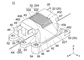
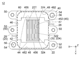
- FIG. 1 It is a top view which shows the intermediate structure of FIG. The outline of the outer circumference of the magnetic core when the magnetic core is formed is drawn by a broken line. It is a bottom view which shows the intermediate structure of FIG. The outline of the hidden magnetic core when the magnetic core is formed is drawn by a broken line. It is a side view which shows the intermediate structure of FIG. A part of the hidden outline of the coil is drawn with a broken line. It is a front view which shows the intermediate structure of FIG. The hidden schematic shape of the turn of the winding part is drawn with a broken line. It is a perspective view which shows the coil of the intermediate structure of FIG. The virtual central axis of the winding part is drawn with a broken line. It is a perspective view which shows the magnetic core of the reactor of FIG.
- a part of the magnetic core is enlarged to schematically draw the structure of the composite magnetic material. It is a top view which shows the magnetic core of FIG. The virtual boundary line between the parts of the magnetic core is drawn with a broken line. It is a side view which shows the modification of the reactor of FIG. A part of the hidden contour of the coil winding part is drawn with a broken line. It is a front view which shows the reactor of FIG. A part of the hidden contour of the coil winding part is drawn with a broken line. It is a perspective view which shows another modification of the reactor of FIG.
- the reactor 10 is a single-phase reactor of a booster (not shown).
- the reactor 10 is used, for example, to boost the current supplied to an EV (Electric Vehicle) motor (not shown). That is, the reactor 10 is arranged in a relatively narrow space and used in a high vibration environment.
- the present invention is not limited to this, and can be applied to various reactors.
- the reactor 10 of the present embodiment includes a coil 20, a holding member 40 made of an insulator, four fastening portions 50 made of an insulator, and a magnetic core 60 made of a soft magnetic material.
- the fastening portion 50 is attached to the holding member 40.
- the reactor 10 of the present embodiment includes only the above-mentioned members (coil 20, holding member 40, fastening portion 50, and magnetic core 60).
- the present invention is not limited to this.
- the reactor 10 may further include a case (not shown) for accommodating the above-mentioned member.
- the coil 20 forms an intermediate structure 12 together with the holding member 40 to which the fastening portion 50 is attached.
- the coil 20 is held by the holding member 40.
- the holding member 40 is molded so as to cover most of the coil 20.
- the coil 20 is partially embedded inside the holding member 40, whereby the holding member 40 holds the coil 20.
- the magnetic core 60 is fixed to the intermediate structure 12.
- the magnetic core 60 forms a reactor 10 together with the intermediate structure 12.
- the intermediate structure 12 has the same structure as the reactor 10 except that it does not include the magnetic core 60. That is, the coil 20, the holding member 40, and the fastening portion 50 of the intermediate structure 12 each have the same structure as the coil 20, the holding member 40, and the fastening portion 50 of the reactor 10.
- the coil 20 of the present embodiment is formed by winding a coated electric wire.
- the coated electric wire is made by covering a conductor made of metal with a thin insulating film made of an insulator.
- the coil 20 has a winding portion 22 and two terminals 28.
- the winding portion 22 winds around a single central axis AX extending along the front-rear direction (X direction).
- the winding portion 22 is an aggregate of a plurality of turns 22T that are wound around the central axis AX by about one round each.
- the two terminals 28 are connected to the turns 22T at both ends of the winding portion 22 in the X direction while exposing the conductor at the tip thereof.
- the winding portion 22 of the present embodiment is formed by edgewise winding a flat-square covered electric wire.
- the winding portion 22 is wound so that the turns 22T are in close contact with each other in the X direction. That is, the winding portion 22 of the present embodiment has a solenoid shape.
- the winding portion 22 By forming the winding portion 22 in this way, the cross-sectional area of the turn 22T in the plane including the central axis AX can be increased.
- the number of turns of the winding portion 22 (that is, the number of turns 22T) can be increased. As a result, a reactor 10 suitable for a large current can be obtained.
- the present invention is not limited to this.
- the winding portion 22 may be sparsely wound so that the turns 22T are separated from each other in the X direction.
- the winding portion 22 may be formed by winding a round wire.
- a central hole 24 is formed in the winding portion 22.
- the central hole 24 is a space surrounded by the winding portion 22 on a vertical plane (YZ plane) orthogonal to the X direction.
- the central hole 24 is open on both sides in the X direction.
- the central hole 24 of the present embodiment is completely surrounded by the solenoid-shaped winding portion 22 in the YZ plane.
- the winding portion 22 has an inner peripheral surface 222 and an outer peripheral surface 224 in the YZ plane.
- the inner peripheral surface 222 faces the central hole 24 in the YZ plane.
- the outer peripheral surface 224 defines the outer circumference of the winding portion 22 in the YZ plane.
- the winding portion 22 has a bottom surface 22L.
- the bottom surface 22L is a part of the outer peripheral surface 224, and is located at the lower end (the end on the ⁇ Z side) of the winding portion 22 in the vertical direction (Z direction) orthogonal to the X direction.
- the winding portion 22 of the present embodiment has a rounded square shape in the YZ plane, whereby the bottom surface 22L extends along a horizontal plane (XY plane) orthogonal to the Z direction.
- the winding portion 22 of the present embodiment has the shape described above.
- the shape of the winding portion 22 of the present invention is not limited to the present embodiment.
- the winding portion 22 may have a track shape in the YZ plane.
- one of the two terminals 28 of the present embodiment is connected to the turn 22T located at the front end (+ X side end) of the winding portion 22 and is connected to the front (+ X direction). Extends to.
- the other of the two terminals 28 of the present embodiment is connected to the turn 22T located at the rear end (-X side end) of the winding portion 22 and extends rearward (-X direction).
- Each of the terminals 28 of the present embodiment is a part of a single coil 20 and is a member integrated with the winding portion 22.
- the present invention is not limited to this.
- each of the terminals 28 may be a member separate from the winding portion 22, or may be connected to the winding portion 22 by welding or the like.
- the winding portion 22 is partially embedded inside the holding member 40.
- the inner peripheral surface 222 of the winding portion 22 is completely covered by the holding member 40.
- most of the outer peripheral surface 224 of the winding portion 22 is covered with the holding member 40.
- most of the front surface (+ X side surface) and rear surface ( ⁇ X side surface) of the winding portion 22 are also covered by the holding member 40.
- each of the terminals 28 with the turn 22T is covered with the holding member 40.
- the tips of the terminals 28 are exposed from the holding member 40. That is, each of the terminals 28 is pulled out from the winding portion 22 to the outside of the holding member 40.
- the terminals 28 extend away from each other along the X direction.
- the portion of the winding portion 22 from which the terminal 28 is pulled out and the shape of each of the terminals 28 are not particularly limited.
- each of the terminals 28 may be pulled out from the upper surface of the winding portion 22 and extended upward.
- the winding portion 22 has an upper exposed portion 32 and a lower exposed portion 34.
- the upper exposed portion 32 and the lower exposed portion 34 are traces of a mold (not shown) used when molding the holding member 40.
- the upper exposed portion 32 and the lower exposed portion 34 are respectively located on the opposite sides of the winding portion 22 in the Z direction.
- the upper exposed portion 32 is exposed upward (+ Z direction) from the holding member 40.
- the lower exposed portion 34 is exposed downward (in the ⁇ Z direction) from the holding member 40. That is, each of the upper exposed portion 32 and the lower exposed portion 34 is exposed from the holding member 40 in the Z direction.
- the upper exposed portion 32 of the present embodiment has one upper flat surface portion 322 and two upper curved surface portions 324.
- Each of the upper flat surface portion 322 and the upper curved surface portion 324 is a part of the outer peripheral surface 224 of the winding portion 22.
- the upper flat surface portion 322 and the upper curved surface portion 324 form the upper surface (+ Z side surface) of the upper exposed portion 32. That is, each of the upper flat surface portion 322 and the upper curved surface portion 324 is a part of the upper surface of the winding portion 22.
- the upper plane portion 322 extends along the XY plane.
- the upper curved surface portion 324 is located on the opposite side of the upper flat surface portion 322 in the lateral direction (Y direction) orthogonal to both the X direction and the Z direction.
- the upper curved surface portion 324 is connected to both edges of the upper flat surface portion 322 in the Y direction, respectively.
- Each of the upper curved surface portions 324 extends outward and downward in the Y direction while drawing an arc. That is, each of the upper curved surface portions 324 has an arc shape in the YZ plane and is exposed to the outside in the Y direction from the holding member 40.
- the lower exposed portion 34 of the present embodiment has one lower flat surface portion 342 and two lower curved surface portions 344.
- Each of the lower flat surface portion 342 and the lower curved surface portion 344 is a part of the outer peripheral surface 224 of the winding portion 22.
- the lower flat surface portion 342 and the lower curved surface portion 344 form the lower surface (the surface on the ⁇ Z side) of the lower exposed portion 34. That is, each of the lower flat surface portion 342 and the lower curved surface portion 344 is a part of the lower surface of the winding portion 22.
- the lower flat surface portion 342 of the present embodiment is the bottom surface 22L of the winding portion 22, and extends along the XY plane.
- the lower curved surface portion 344 is located on the opposite side of the lower flat surface portion 342 in the Y direction, respectively.
- the lower curved surface portion 344 is connected to both edges of the lower flat surface portion 342 in the Y direction, respectively.
- Each of the lower curved surface portions 344 extends outward and upward in the Y direction while drawing an arc. That is, each of the lower curved surface portions 344 has an arc shape in the YZ plane and is exposed to the outside in the Y direction from the holding member 40.
- the holding member 40 of the present embodiment has two side walls 44.
- each of the side walls 44 has a flat plate shape extending parallel to the XZ plane.
- the side walls 44 are separated from each other in the Y direction and extend parallel to each other along the XZ plane.
- the magnetic core 60 of the present embodiment is a gapless score composed of only the composite magnetic material 60M. That is, the magnetic core 60 extends continuously in the XY plane without a break.
- the composite magnetic material 60M contains a binder 60B made of an insulator such as a thermosetting resin and a magnetic powder 60P dispersed and arranged on the binder 60B.
- the magnetic powder 60P is made of a soft magnetic material.
- the magnetic powder 60P is bound to each other by the binder 60B and is insulated from each other.
- the composite magnetic material 60M may contain other materials such as a non-magnetic filler in addition to the binder 60B and the magnetic powder 60P.
- Such a gapless score made of the composite magnetic material 60M is not easily damaged and is suitable for the reactor 10 (see FIG. 1) used in a high vibration environment.
- the magnetic core 60 has a middle leg 62 and two outer portions 64.
- Each of the outer portions 64 has an outer leg 66 and two connecting portions 68.
- the connecting portion 68 connects both ends of the outer leg 66 in the X direction to both ends of the middle leg 62 in the X direction, respectively. In this embodiment, these sites extend continuously without gaps from each other.
- the magnetic core 60 has an upper surface 60U, a lower surface 60L, and an outer peripheral surface 60E.
- Each of the upper surface 60U and the lower surface 60L of the present embodiment is a smooth plane parallel to the XY plane, and extends continuously over all the portions of the magnetic core 60.
- the outer peripheral surface 60E defines the outer circumference of the magnetic core 60 in the XY plane.
- the outer peripheral surface 60E of the present embodiment is a closed curved surface extending in parallel with the Z direction.
- the middle leg 62 of the magnetic core 60 is located inside the central hole 24. That is, the middle leg 62 of the magnetic core 60 is surrounded by the winding portion 22 in the YZ plane.
- the winding portion 22 is located between the two outer legs 66 in the Y direction.
- the two side walls 44 of the holding member 40 are provided corresponding to the outer legs 66, respectively. That is, the holding member 40 has two side walls 44 corresponding to the outer legs 66, respectively. Each of the side walls 44 is located between the corresponding outer leg 66 and the winding portion 22 in the Y direction.
- the magnetic core 60 of the present embodiment has the above-mentioned structure, whereby it has a shape like an EE core in the XY plane. Further, the magnetic core 60 of the present embodiment has a shape that is mirror-symmetrical with respect to the XY plane. However, the present invention is not limited to this, and as long as the magnetic core 60 has a shape like an EE core in the XY plane, the structure of the magnetic core 60 can be variously deformed. For example, unevenness may be formed on each of the upper surface 60U and the lower surface 60L.
- the reactor 10 of the present embodiment is manufactured by forming a magnetic core 60 having a shape like an EE core around the side wall 44 of the holding member 40. That is, the reactor 10 of the present embodiment includes a coil 20 having a single winding portion 22 and a magnetic core 60 shaped like an EE core. According to this structure, the magnetic path length can be shortened and the cross-sectional area of the magnetic path can be increased as compared with a conventional reactor composed of a so-called spectacle coil and a magnetic core having a shape like a UU core. That is, the inductance of the reactor 10 can be increased as compared with the conventional technique.
- the outer portion 64 of the formed magnetic core 60 is arranged so as to face the side surface of the winding portion 22 in the Y direction. Will be done. If the side surface of the winding portion 22 is exposed toward the outer portion 64 of the magnetic core 60, for example, if the insulating film (not shown) on the side surface of the winding portion 22 is damaged, the winding portion 22 The insulation between the side surface and the outer portion 64 of the magnetic core 60 may be reduced.
- the holding member 40 needs to completely cover the side surface of the winding portion 22 facing the magnetic core 60 and insulate it from the magnetic core 60. That is, the holding member 40 needs to be molded so that the side surface of the winding portion 22 is embedded in the holding member 40.
- the holding member 40 when the holding member 40 is molded in this way, it is necessary to add the coil 20 in the Z direction and hold the coil 20 so as not to move in the XY plane. More specifically, it is necessary to hold the side surface of the winding portion 22 by pressing it with a mold (not shown). As a result of holding by the mold, a trace of the mold is inevitably formed on the side wall 44 of the holding member 40 in which the coil 20 is embedded. More specifically, on the side wall 44 of the holding member 40, a portion where the side surface of the winding portion 22 is exposed toward the magnetic core 60 is formed.
- the holding member 40 in which the coil 20 is embedded has a new structure which has not been conventionally found. According to this new structure, the winding portion 22 of the coil 20 is completely embedded inside the holding member 40, except for the upper exposed portion 32 and the lower exposed portion 34, as described below.
- the holding member 40 can be molded from a thermosetting material such as resin.
- the coil 20 when forming the holding member 40, first, the coil 20 (see FIG. 11) is manufactured. Next, the winding portion 22 is arranged inside a mold (not shown), and the upper exposed portion 32 and the lower exposed portion 34 of the coil 20 are vertically sandwiched by the mold. For example, the lower exposed portion 34 is arranged on the lower mold (not shown). Next, the upper exposed portion 32 is pressed downward by the upper mold (not shown), whereby the lower exposed portion 34 is pressed against the lower mold. At this time, the upper curved surface portion 324 is sandwiched by the upper mold from both sides in the Y direction. By sandwiching the winding portion 22 with the mold as described above, the winding portion 22 can be positioned in the Z direction and the XY plane.
- thermosetting material is injected into the inside of the mold.
- thermosetting material is solidified.
- remove the mold remove the mold.
- the fastening portion 50 is attached to the solidified thermosetting material.
- the holding member 40 is formed. That is, the intermediate structure 12 is manufactured.
- the winding portion 22 can be held so as not to move in the Z direction and the XY plane. That is, the holding member 40 of the present embodiment can be formed so that the winding portion 22 is partially embedded.
- the present invention is not limited to this, and the method for forming the holding member 40 can be variously modified as needed.
- the lower curved surface portion 344 may be sandwiched by lower molds (not shown) from both sides in the Y direction.
- the front surface and the rear surface of the lower exposed portion 34 may be sandwiched by the lower mold from both sides in the X direction. According to this method, the winding portion 22 can be more reliably positioned on the XY plane.
- the structures of the upper exposed portion 32 and the lower exposed portion 34 can be variously deformed as long as the coil 20 can be positioned when forming the holding member 40.
- the entire upper surface of the upper exposed portion 32 may have an arc shape protruding upward in the YZ plane. That is, the upper exposed portion 32 may have only one upper curved surface portion 324. Regardless of the shape of the upper exposed portion 32, the upper curved surface portion 324 may be exposed from the holding member 40 on both sides in the Y direction. Further, the entire lower surface of the lower exposed portion 34 may have an arc shape protruding downward in the YZ plane. That is, the lower exposed portion 34 may have only one lower curved surface portion 344. The lower exposed portion 34 may have only the lower flat portion 342. When the lower curved surface portion 344 is provided, regardless of the shape of the lower exposed portion 34, if the lower curved surface portion 344 is exposed from the holding member 40 on both sides in the Y direction. good.
- the upper end (+ Z side end) of the upper exposed portion 32 is located below the upper end of the holding member 40, and the lower exposed portion 34 The lower end is located below the lower end of the holding member 40. That is, the front surface and the rear surface of the upper exposed portion 32 are covered with the holding member 40, and the front surface and the rear surface of the lower exposed portion 34 are exposed from the holding member 40.
- the present invention is not limited to this, and the positional relationship between the upper exposed portion 32 and the lower exposed portion 34 with respect to the holding member 40 can be variously modified as necessary.
- the holding member 40 of the present embodiment has a lower support portion 42, an upper support portion 45, two outer wall portions 48, and two connections. It has a part 54 and.
- the holding member 40 of the present embodiment has only the above-mentioned portion.
- the present invention is not limited to this.
- the holding member 40 may have yet another portion in addition to the above-mentioned portion.
- each of the above-mentioned parts may be provided as needed.
- each of the side wall 44s of the present embodiment is integrally formed with the holding member 40.
- each of the side walls 44 is part of the holding member 40. More specifically, each of the side walls 44 is an intermediate portion of the holding member 40 in the Z direction.
- the side wall 44 displays the portions on both sides of the winding portion 22 in the Y direction in the XY plane. Each is completely covered. Specifically, of the portions on both sides of the winding portion 22 in the Y direction, the inner peripheral surface 222 and the outer peripheral surface 224 are completely covered by the two side walls 44. In addition, of the portions on both sides of the winding portion 22 in the Y direction, the front end and the rear end are completely covered by the two side walls 44.
- Each of the side wall 44s of the present embodiment has the above-mentioned structure.
- the structure of each side wall 44 is not particularly limited.
- the lower support portion 42 of the present embodiment is integrally formed with the holding member 40.
- the lower support portion 42 is a part of the holding member 40. More specifically, the lower support portion 42 is a lower portion (—Z side portion) of the holding member 40.
- the lower support portion 42 has a flat plate shape extending parallel to the XY plane.
- each of the side walls 44 extends upward from the lower support portion 42. That is, the lower support portion 42 supports the side wall 44.
- the lower support portion 42 partially covers the lower portion of the winding portion 22 in the XY plane. Specifically, of the lower portion of the winding portion 22, the inner peripheral surface 222 is completely covered by the lower support portion 42. Of the lower portions of the winding portion 22, the outer peripheral surface 224, the front end and the rear end are partially covered by the lower support portion 42.
- a lower opening 422 is formed in the lower support portion 42.
- the lower opening 422 is a space that opens downward.
- the lower opening 422 is located in the middle of the lower support portion 42 in the XY plane and is surrounded by the lower surface 428 of the lower support portion 42.
- the lower exposed portion 34 which is a lower portion of the winding portion 22, protrudes downward from the lower opening 422 and is exposed. For details, referring to FIGS. 9 and 10, the lower exposed portion 34 projects downward beyond the lower surface 428 of the lower support portion 42.
- the lower support portion 42 of the present embodiment has the above-mentioned structure. However, as long as the lower support portion 42 covers and insulates the inner peripheral surface 222 of the lower portion of the winding portion 22 and exposes the lower exposed portion 34 downward, the structure of the lower support portion 42 is , Not particularly limited.
- the upper support portion 45 of the present embodiment is integrally formed with the holding member 40.
- the upper support portion 45 is a part of the holding member 40. More specifically, the upper support portion 45 is an upper portion (+ Z side portion) of the holding member 40.
- each of the side walls 44 extends vertically between the lower support portion 42 and the upper support portion 45. That is, the upper support portion 45 is supported by the side wall 44.
- the upper support portion 45 has a flat plate shape extending parallel to the XY plane as a whole.
- the upper support portion 45 has a front upper support portion 46 and a rear upper support portion 47. That is, the holding member 40 of the present embodiment has a front upper support portion 46 and a rear upper support portion 47.
- the front upper support portion 46 is a portion of the upper support portion 45 that partially projects forward.
- the rear upper support portion 47 is a portion of the upper support portion 45 that partially projects rearward.
- the front upper support portion 46 is located in front of the winding portion 22.
- the rear upper support portion 47 is located behind the winding portion 22.
- the front upper support portion 46 and the rear upper support portion 47 each face a part of the lower support portion 42 in the Z direction.
- the upper support portion 45 of the present embodiment has two upper side walls 456 corresponding to the side walls 44 in addition to the front upper support portion 46 and the rear upper support portion 47.
- Each of the upper side walls 456 is a portion of the upper support portion 45 that partially projects outward in the Y direction.
- Each of the upper side walls 456 is connected to the upper end of the corresponding side wall 44.
- the upper support portion 45 partially covers the upper portion of the winding portion 22 in the XY plane. Specifically, of the upper portions of the winding portion 22, the inner peripheral surface 222, the front end and the rear end are completely covered by the upper support portion 45. Of the upper portion of the winding portion 22, the outer peripheral surface 224 is partially covered by the upper support portion 45.
- an upper opening 452 is formed in the upper support portion 45.
- the upper opening 452 is a space that opens upward.
- the upper opening 452 is located in the middle of the upper support portion 45 in the XY plane.
- the upper exposed portion 32 which is a part of the upper portion of the winding portion 22, is located inside the upper opening 452 and is exposed from the upper support portion 45. ..
- the upper support portion 45 of the present embodiment has the above-mentioned structure.
- the present invention is not limited to this.
- the structure of the upper support portion 45 is particularly high. Not limited.
- each of the outer wall portions 48 of the present embodiment is integrally formed with the holding member 40.
- each of the outer wall portions 48 is a part of the holding member 40.
- the outer wall portion 48 is provided on the lower support portion 42 so as to correspond to the side wall 44, respectively.
- each of the outer wall portions 48 are located on both sides of the lower support portion 42 in the Y direction, respectively.
- Each of the outer wall portions 48 extends upward from the lower support portion 42, partially surrounding the corresponding side wall 44 in the XY plane.
- each of the outer wall portions 48 has an inner peripheral surface 482 in the XY plane.
- the intermediate portion of each of the inner peripheral surfaces 482 in the X direction extends linearly along the X direction. Both ends of the inner peripheral surface 482 in the X direction extend inward in the Y direction while drawing an arc.
- a groove is formed between each of the inner peripheral surfaces 482 and the corresponding side wall 44.
- each of the outer wall portions 48 of the present embodiment has the above-mentioned structure.
- the present invention is not limited to this.
- each of the outer wall portions 48 may be attached to and fixed to the lower support portion 42 after being formed separately from the lower support portion 42. Further, each of the outer wall portions 48 may be provided as needed.
- each of the connecting portions 54 of the present embodiment is a portion for fixing the bus bar 80 made of a conductor such as metal to the holding member 40.
- each of the connecting portions 54 of the present embodiment is integrally formed with the holding member 40.
- each of the connecting portions 54 is a part of the holding member 40.
- the connection portion 54 of the present embodiment is provided so as to correspond to the outer wall portion 48, respectively.
- One of the connecting portions 54 projects forward from the corresponding outer wall portion 48.
- the other of the connecting portions 54 projects rearward from the corresponding outer wall portion 48.
- a connection hole 56 is formed in each of the connection portions 54.
- Each of the connecting holes 56 is a hole with a bottom recessed downward.
- Each of the connection holes 56 is open upward.
- connection portions 54 of the present embodiment has the above-mentioned structure.
- the present invention is not limited to this.
- the arrangement of the connecting portion 54 is not particularly limited.
- each of the connecting portions 54 may be provided as needed.
- each of the fastening portions 50 of the present embodiment is a portion for fixing the reactor 10 to an object (not shown) such as a circuit board.
- the holding member 40 of the present embodiment is provided with four fastening portions 50 for fastening the reactor 10 to the object.
- the present invention is not limited to this.
- the number of fastening portions 50 may be 3 or less, or 5 or more. Further, the fastening portion 50 may be provided as needed.
- the fastening portion 50 of the present embodiment is located outside the winding portion 22 in the X direction. Specifically, two of the fastening portions 50 project forward from the lower support portion 42. The other two of the fastening portions 50 project rearward from the lower support portion 42. Referring to FIGS. 8 and 9, each lower surface 508 of the fastening portion 50 is in the same position as the lower surface 428 of the lower support portion 42 in the Z direction and extends continuously from the lower surface 428. That is, each of the lower surface 508 of the fastening portion 50 is flush with the lower surface 428 of the lower support portion 42. Referring to FIGS. 6 to 8, fastening holes 52 are formed in each of the fastening portions 50. Each of the fastening holes 52 penetrates the fastening portion 50 in the Z direction.
- the portions of the holding member 40 are integrally formed with each other.
- two of the fastening portions 50 are located directly below the slide path of the slide mold (not shown). It is difficult to mold the fastening portion 50 arranged in this way at the same time as the holding member 40. Therefore, each of the fastening portions 50 of the present embodiment is attached to the lower support portion 42 after the holding members 40 are integrally formed with each other.
- each of the fastening portions 50 is attached to the lower support portion 42.
- each of the fastening portions 50 can be arranged outside the lower support portion 42 in the X direction without increasing the number of molding steps. That is, according to the present embodiment, the manufacturing cost of the reactor 10 can be reduced.
- the present invention is not limited to this.
- each of the fastening portions 50 may be arranged outside the lower support portion 42 in the Y direction. According to this arrangement, the fastening portion 50 can be formed simultaneously and integrally with the holding member 40, whereby the manufacturing cost of the reactor 10 can be further reduced.
- the magnetic core 60 of the present embodiment is formed by injecting a magnetic slurry composed of the composite magnetic material 60M onto the intermediate structure 12.
- the magnetic core 60 of the present embodiment fills the inside of the central hole 24 of the intermediate structure 12 and surrounds each of the side walls 44 of the intermediate structure 12 in an XY plane. It is injection-molded in such a way. That is, the reactor 10 of the present embodiment includes an intermediate structure 12 and an injection-molded magnetic core 60.
- the winding portion 22 may be directly covered by the magnetic slurry. That is, the winding portion 22 may not be insulated from the formed magnetic core 60.
- each of the side wall 44 of the holding member 40 is located between the winding portion 22 and the magnetic core 60 in the Y direction, and the winding portion 22 is insulated from the magnetic core 60. are doing. Specifically, the portion of the winding portion 22 located above the lower support portion 42 is completely covered and insulated by the holding member 40 except for the upper exposed portion 32. The upper exposed portion 32 is a blind spot from the portion where the magnetic slurry is ejected. In addition, the lower support portion 42 covers the portion of the winding portion 22 located below the lower support portion 42 in the Z direction. Therefore, the reactor 10 having the coil 20 partially embedded inside the holding member 40 can be provided with the magnetic core 60 having a shape like an EE core.
- the winding portion 22 does not come into contact with the magnetic slurry.
- the method of forming the magnetic core 60 is not limited to this embodiment.
- the magnetic core 60 may be a casting core.
- the reactor of the present embodiment can be manufactured by using the coil 20 having a single winding portion 22 and the magnetic core 60 having a shape like an EE core. That is, according to the present embodiment, it is possible to provide a reactor 10 having a coil 20 partially embedded inside the holding member 40 and having a relatively large inductance.
- the magnetic core 60 of the present embodiment is formed only of the composite magnetic material 60M.
- the magnetic core 60 may include a dust core (not shown) made of a soft magnetic material in addition to a portion made of the composite magnetic material 60M. That is, the magnetic core 60 may be formed from the composite magnetic material 60M at least partially. For example, a portion made of the composite magnetic material 60M may be formed by embedding a plurality of small pieces of the dust core. By including the dust core in the magnetic core 60, the inductance of the reactor 10 (see FIG. 1) can be increased.
- the magnetic core 60 may be formed only from the dust core.
- a plurality of dust cores may be fixed to each other with an adhesive to form a magnetic core 60. That is, the magnetic core 60 may be an assembly in which a plurality of dust cores are joined to each other.
- each of the side wall 44s of the present embodiment does not have a hole open toward both the winding portion 22 and the outer leg 66. With this structure, the winding portion 22 can be more reliably insulated from the magnetic core 60.
- the present invention is not limited to this.
- each of the side walls 44 may be formed with a hole that does not interfere with the insulation.
- the upper exposed portion 32 of the present embodiment is visible when the reactor 10 is viewed along the Y direction.
- the present invention is not limited to this.
- the upper side wall 456 may be located outside the upper exposed portion 32 in the Y direction while being separated from the upper curved surface portion 324 of the upper exposed portion 32 in the Y direction.
- the upper exposed portion 32 may be seamlessly surrounded by the holding member 40 in the XY plane. According to this modification, the winding portion 22 can be more reliably insulated from the magnetic core 60.
- the magnetic core 60 of the present embodiment is located between the upper exposed portion 32 and the lower exposed portion 34 of the winding portion 22 in the Z direction. That is, the magnetic core 60 of the present embodiment is arranged so that the position of the magnetic core 60 in the Z direction does not overlap with the positions of the upper exposed portion 32 and the lower exposed portion 34 in the Z direction. According to this arrangement, the winding portion 22 can be more reliably insulated from the magnetic core 60.
- the present invention is not limited to this. For example, when the upper exposed portion 32 is seamlessly surrounded by the holding member 40 in the XY plane, the position of the magnetic core 60 in the Z direction may overlap with the position of the upper exposed portion 32 in the Z direction.
- the lower support portion 42, the front upper support portion 46, the rear upper support portion 47, and the outer wall portion 48 of the holding member 40 of the present embodiment are provided as follows.
- the lower support portion 42 is in contact with the lower surface 60L of the magnetic core 60 and supports the lower surface 60L.
- each of the front upper support portion 46 and the rear upper support portion 47 is in contact with the upper surface 60U of the magnetic core 60.
- each of the outer wall portions 48 is in contact with the outer peripheral surface 60E of the magnetic core 60 in the XY plane.
- each inner peripheral surface 482 of the outer wall portion 48 is in contact with the outer peripheral surface 60E of the magnetic core 60 in the XY plane.
- the magnetic core 60 is attached to the lower support portion 42 and the front. It can be injection-molded at a predetermined position defined by the upper support portion 46, the rear upper support portion 47, and the outer wall portion 48.
- the magnetic core 60 of the present embodiment is sandwiched between the front upper support portion 46 and the rear upper support portion 47 and the lower support portion 42 in the Z direction, and 2 in the X direction and the Y direction, respectively. It is sandwiched between the two outer peripheral surfaces 60E. That is, the magnetic core 60 of the present embodiment is reliably positioned so as not to move in the Z direction and the XY plane. According to this structure, it is possible to prevent a change in inductance due to a displacement of the magnetic core 60, and it is possible to prevent damage to the magnetic core 60.
- the present invention is not limited to this.
- the front upper support portion 46, the rear upper support portion 47, and the outer wall portion 48 may be provided as needed.
- the reactor 10 of the present embodiment is fixed to an object (not shown) such as a circuit board at the time of use.
- an object such as a circuit board at the time of use.
- four nuts 82 are attached to the fastening holes 52 of the four fastening portions 50 of the reactor 10, respectively.
- Each of the nuts 82 may be press-fitted into the fastening hole 52, or may be insert-molded into the fastening portion 50 when the fastening portion 50 is molded.
- screws (not shown) are screwed into the nuts 82, respectively, to fix the fastening portion 50 to the object.
- the reactor 10 of the present embodiment is fixed to an object (not shown) and then connected to a power source (not shown) using two bus bars 80.
- two nuts 84 are attached to the connection holes 56 of the two connection portions 54, respectively.
- Each of the nuts 84 may be press-fitted into the connection hole 56, or may be insert-molded into the connection portion 54 when the holding member 40 is molded.
- the upper end of the bus bar 80 is fixed and connected to the terminal 28 of the coil 20 by welding or the like.
- a screw (not shown) is screwed into the nut 84 through a passage hole (not shown) at the lower end of the bus bar 80 and a passage hole (not shown) of a conductive member (not shown) made of a conductor.
- the bus bar 80 is fixed and connected to each of the two conductive members.
- the magnetic core 60 of the present embodiment is formed of the composite magnetic material 60M (see FIG. 12), it is difficult for magnetic saturation to occur even when a large current flows through the coil 20. Therefore, the reactor 10 of the present embodiment can be miniaturized while maintaining the magnetic characteristics. That is, according to the present embodiment, a small reactor 10 suitable for a large current can be obtained.
- the inductance 10 provided with the magnetic core 60 composed of only the composite magnetic material 60M has a relatively low current of about 30 to 40 A flowing through the coil 20 as compared with the inductance provided with the dust core.
- the initial inductance which is the inductance at the time, is low. Therefore, it is necessary to pass a current for a relatively long time in order to obtain the required boosting performance.
- the core loss increases as the current flows.
- the magnetic core 60 of the present embodiment is formed of a low-loss material described below, whereby the core loss can be reduced.
- the magnetic powder 60P (see FIG. 12) of the composite magnetic body 60M (see FIG. 12) contained in the magnetic core 60 of the present embodiment has a composition formula Fe X1 B X2 Si X3 P X4 C X5 Cu X6 Cr except for unavoidable impurities.
- An alloy powder represented by X7 , X1 + X2 + X3 + X4 + X5 + X6 + X7 100 at%, 79 ⁇ X1 ⁇ 86 at%, 4 ⁇ X2 ⁇ 13 at%, 0 ⁇ X3 ⁇ 8 at%, 1 ⁇ X4 ⁇ 14 at%, 0 ⁇ X5 ⁇ 5 at%, 0.4 ⁇ X6 ⁇ 1.4 at%, 0 ⁇ X7 ⁇ 3 at%.
- the core loss of the magnetic core 60 can be reduced.
- the present invention is not limited to this, and the composition of the magnetic powder 60P may be set in consideration of various magnetic characteristics required for the reactor 10.
- the magnetic powder 60P contains a part of Fe in the above composition formula as Co, Ni, V, Nb, Zr, Hf, Mo, Ta, W, Ag, Au, Pd, K, Ca, Mg
- the alloy powder may be substituted with one or more elements selected from Sn, Zn, Ti, Al, Mn, S, O, N, Y and rare earth elements.
- one or more elements selected from rare earth elements are 3 at% or less of the total composition.
- the alloy powder having the above composition contains nanocrystals of ⁇ Fe.
- the shape of the nanocrystals is preferably substantially spherical.
- the average particle size (D50) of the nanocrystals when the nanocrystals are approximated to a true sphere is preferably 5 nm or more and 50 nm or less.
- the bottom surface 22L of the winding portion 22 of the present embodiment is located below the holding member 40. According to this arrangement, when the reactor 10 is fixed to an object (not shown) such as a circuit board, the bottom surface 22L can be brought into contact with the object to dissipate heat. That is, the bottom surface 22L of the present embodiment functions as a heat radiating unit. Further, referring to FIG.
- the upper exposed portion 32 of the present embodiment functions as a heat radiating portion that radiates heat into the air.
- the present invention is not limited to this.
- the position of the bottom surface 22L of the winding portion 22 in the Z direction can be deformed as needed.
- the reactor 10 of the present embodiment has a shape that is 180-degree rotationally symmetric when viewed from above along the Z direction.
- the shape of the reactor 10 when rotated 180 degrees around an axis extending parallel to the Z direction is the same as the shape before rotation, except for tolerances.
- the same two parts can be used as the two busbars 80, thereby reducing the manufacturing cost of the reactor 10.
- the strength design of the reactor 10 becomes easy.
- the reactor 10 of the present embodiment has a shape that is 180-degree rotationally symmetric, including the upper exposed portion 32 of the winding portion 22.
- each of the upwardly exposed turns 22T extends straight along the Y direction.
- the present invention is not limited to this.
- each of the turns 22T may be slightly oblique to the Y direction. That is, the reactor 10 may have a shape substantially 180-degree rotationally symmetric when viewed from above along the Z direction.
- the reactor 10 of the present embodiment can be further deformed in addition to the modification already described.
- two modifications of the reactor 10 will be described.
- the reactor 10A according to the first modification has the same coil 20, magnetic core 60, and fastening portion 50 as the reactor 10, and the holding member 40 of the reactor 10. It is provided with a holding member 40A different from the above.
- the lower support portion 42 of the holding member 40A is located below the lower support portion 42 of the holding member 40.
- the outer wall portion 48A of the holding member 40A extends longer in the Z direction than the outer wall portion 48 of the holding member 40.
- the holding member 40A has the same structure as the holding member 40 except for this difference.
- the lower surface 508 of the fastening portion 50 can be flush with the bottom surface 22L of the winding portion 22. That is, the lower surface of the entire lower support portion 42 including the lower surface 508 of the fastening portion 50 can be flush with the bottom surface 22L of the winding portion 22. According to this modification, the height of the reactor 10A can be easily controlled when the reactor 10A is manufactured, whereby the manufacturing cost of the reactor 10A can be reduced.
- the reactor 10B according to the second modification has the same coil 20, magnetic core 60, and fastening portion 50 as the reactor 10, and has a holding member 40B different from the holding member 40 of the reactor 10.
- the holding member 40B has an upper wall portion 454B that the holding member 40 does not have.
- the upper wall portion 454B is provided so as to partially close the upper opening 452 of the upper support portion 45. Specifically, the upper wall portion 454B extends along the X direction over the entire upper opening 452 so as to cover the intermediate portion of the upper flat portion 322 of the winding portion 22 in the Y direction.
- the holding member 40B has the same structure as the holding member 40 except for this difference.
- the upper exposed portion 32 of the winding portion 22 can be partially closed while the holding member 40B can be molded, thereby further improving the insulating property of the winding portion 22. be able to.
- the present invention is based on Japanese Patent Application No. 2020-177981 filed with the Japan Patent Office on October 23, 2020, the contents of which form a part of the present specification by reference.
Landscapes
- Engineering & Computer Science (AREA)
- Power Engineering (AREA)
- Chemical & Material Sciences (AREA)
- Dispersion Chemistry (AREA)
- Physics & Mathematics (AREA)
- Electromagnetism (AREA)
- Composite Materials (AREA)
- Materials Engineering (AREA)
- Inorganic Chemistry (AREA)
- Crystallography & Structural Chemistry (AREA)
- Coils Or Transformers For Communication (AREA)
- Soft Magnetic Materials (AREA)
- Housings And Mounting Of Transformers (AREA)
Priority Applications (3)
| Application Number | Priority Date | Filing Date | Title |
|---|---|---|---|
| EP21882452.2A EP4213171B1 (en) | 2020-10-23 | 2021-09-01 | Reactor |
| US18/032,352 US20230386734A1 (en) | 2020-10-23 | 2021-09-01 | Reactor |
| CN202180072303.2A CN116508119A (zh) | 2020-10-23 | 2021-09-01 | 电抗器 |
Applications Claiming Priority (2)
| Application Number | Priority Date | Filing Date | Title |
|---|---|---|---|
| JP2020-177981 | 2020-10-23 | ||
| JP2020177981A JP7613880B2 (ja) | 2020-10-23 | 2020-10-23 | リアクトル |
Publications (1)
| Publication Number | Publication Date |
|---|---|
| WO2022085311A1 true WO2022085311A1 (ja) | 2022-04-28 |
Family
ID=81290433
Family Applications (1)
| Application Number | Title | Priority Date | Filing Date |
|---|---|---|---|
| PCT/JP2021/032195 Ceased WO2022085311A1 (ja) | 2020-10-23 | 2021-09-01 | リアクトル |
Country Status (5)
| Country | Link |
|---|---|
| US (1) | US20230386734A1 (https=) |
| EP (1) | EP4213171B1 (https=) |
| JP (1) | JP7613880B2 (https=) |
| CN (1) | CN116508119A (https=) |
| WO (1) | WO2022085311A1 (https=) |
Cited By (1)
| Publication number | Priority date | Publication date | Assignee | Title |
|---|---|---|---|---|
| JP2023167281A (ja) * | 2022-05-11 | 2023-11-24 | 株式会社トーキン | リアクトル構造体 |
Families Citing this family (1)
| Publication number | Priority date | Publication date | Assignee | Title |
|---|---|---|---|---|
| EP4113549A1 (en) * | 2021-06-28 | 2023-01-04 | Valeo eAutomotive France SAS | A magnetic core device and a power converter |
Citations (6)
| Publication number | Priority date | Publication date | Assignee | Title |
|---|---|---|---|---|
| JP2013143454A (ja) * | 2012-01-10 | 2013-07-22 | Sumitomo Electric Ind Ltd | リアクトル、コア部品、リアクトルの製造方法、コンバータ、及び電力変換装置 |
| JP2018190910A (ja) * | 2017-05-11 | 2018-11-29 | 三菱電機株式会社 | リアクトル装置およびその製造方法 |
| JP6593780B2 (ja) | 2017-03-03 | 2019-10-23 | 株式会社オートネットワーク技術研究所 | リアクトル |
| JP2020053461A (ja) * | 2018-09-25 | 2020-04-02 | 株式会社タムラ製作所 | リアクトル及びその製造方法 |
| JP2020158831A (ja) * | 2019-03-26 | 2020-10-01 | Tdk株式会社 | 軟磁性合金および磁性部品 |
| JP2020177981A (ja) | 2019-04-16 | 2020-10-29 | オムロン株式会社 | 制御装置および実装装置 |
Family Cites Families (1)
| Publication number | Priority date | Publication date | Assignee | Title |
|---|---|---|---|---|
| JP2019134127A (ja) * | 2018-02-02 | 2019-08-08 | トヨタ自動車株式会社 | リアクトル |
-
2020
- 2020-10-23 JP JP2020177981A patent/JP7613880B2/ja active Active
-
2021
- 2021-09-01 US US18/032,352 patent/US20230386734A1/en active Pending
- 2021-09-01 WO PCT/JP2021/032195 patent/WO2022085311A1/ja not_active Ceased
- 2021-09-01 CN CN202180072303.2A patent/CN116508119A/zh active Pending
- 2021-09-01 EP EP21882452.2A patent/EP4213171B1/en active Active
Patent Citations (6)
| Publication number | Priority date | Publication date | Assignee | Title |
|---|---|---|---|---|
| JP2013143454A (ja) * | 2012-01-10 | 2013-07-22 | Sumitomo Electric Ind Ltd | リアクトル、コア部品、リアクトルの製造方法、コンバータ、及び電力変換装置 |
| JP6593780B2 (ja) | 2017-03-03 | 2019-10-23 | 株式会社オートネットワーク技術研究所 | リアクトル |
| JP2018190910A (ja) * | 2017-05-11 | 2018-11-29 | 三菱電機株式会社 | リアクトル装置およびその製造方法 |
| JP2020053461A (ja) * | 2018-09-25 | 2020-04-02 | 株式会社タムラ製作所 | リアクトル及びその製造方法 |
| JP2020158831A (ja) * | 2019-03-26 | 2020-10-01 | Tdk株式会社 | 軟磁性合金および磁性部品 |
| JP2020177981A (ja) | 2019-04-16 | 2020-10-29 | オムロン株式会社 | 制御装置および実装装置 |
Non-Patent Citations (1)
| Title |
|---|
| See also references of EP4213171A4 |
Cited By (1)
| Publication number | Priority date | Publication date | Assignee | Title |
|---|---|---|---|---|
| JP2023167281A (ja) * | 2022-05-11 | 2023-11-24 | 株式会社トーキン | リアクトル構造体 |
Also Published As
| Publication number | Publication date |
|---|---|
| JP7613880B2 (ja) | 2025-01-15 |
| CN116508119A (zh) | 2023-07-28 |
| EP4213171B1 (en) | 2025-12-17 |
| JP2022069044A (ja) | 2022-05-11 |
| EP4213171A4 (en) | 2024-07-31 |
| EP4213171A1 (en) | 2023-07-19 |
| US20230386734A1 (en) | 2023-11-30 |
Similar Documents
| Publication | Publication Date | Title |
|---|---|---|
| US9147521B2 (en) | Reactor | |
| JP5413680B2 (ja) | リアクトルの製造方法 | |
| JP4514031B2 (ja) | コイル部品及びコイル部品製造方法 | |
| CN1892932B (zh) | 磁性元件 | |
| US11657955B2 (en) | Surface mount inductor | |
| JP6599933B2 (ja) | ノイズフィルタ及びノイズ低減ユニット | |
| JP6784275B2 (ja) | 表面実装インダクタおよびその製造方法 | |
| WO2022085311A1 (ja) | リアクトル | |
| JP2018133500A (ja) | リアクトルおよびその製造方法 | |
| JP2004193215A (ja) | 電子部品及びその製造方法 | |
| JP7061291B2 (ja) | リアクトル | |
| JP2011142193A (ja) | リアクトル | |
| WO2017110567A1 (ja) | 複合材料成形体、リアクトル、及び複合材料成形体の製造方法 | |
| JP6851257B2 (ja) | リアクトル | |
| JP2007201203A (ja) | リアクトル | |
| JP6552332B2 (ja) | コイル部品 | |
| JP6722790B2 (ja) | コイル部品 | |
| WO2017030084A1 (ja) | 複合材料成形体、及びリアクトル | |
| JP7437193B2 (ja) | リアクトル | |
| JP7743215B2 (ja) | リアクトル | |
| JP7296047B2 (ja) | リアクトル | |
| JP2019114578A (ja) | リアクトル | |
| JP7657662B2 (ja) | リアクトル | |
| JP7377006B2 (ja) | リアクトル | |
| JP7699441B2 (ja) | リアクトル |
Legal Events
| Date | Code | Title | Description |
|---|---|---|---|
| 121 | Ep: the epo has been informed by wipo that ep was designated in this application |
Ref document number: 21882452 Country of ref document: EP Kind code of ref document: A1 |
|
| WWE | Wipo information: entry into national phase |
Ref document number: 2021882452 Country of ref document: EP |
|
| ENP | Entry into the national phase |
Ref document number: 2021882452 Country of ref document: EP Effective date: 20230413 |
|
| WWE | Wipo information: entry into national phase |
Ref document number: 18032352 Country of ref document: US |
|
| WWE | Wipo information: entry into national phase |
Ref document number: 202180072303.2 Country of ref document: CN |
|
| NENP | Non-entry into the national phase |
Ref country code: DE |
|
| WWG | Wipo information: grant in national office |
Ref document number: 2021882452 Country of ref document: EP |