WO2022085112A1 - 冷熱源ユニットおよび冷凍サイクル装置 - Google Patents
冷熱源ユニットおよび冷凍サイクル装置 Download PDFInfo
- Publication number
- WO2022085112A1 WO2022085112A1 PCT/JP2020/039541 JP2020039541W WO2022085112A1 WO 2022085112 A1 WO2022085112 A1 WO 2022085112A1 JP 2020039541 W JP2020039541 W JP 2020039541W WO 2022085112 A1 WO2022085112 A1 WO 2022085112A1
- Authority
- WO
- WIPO (PCT)
- Prior art keywords
- compressor
- oil return
- heat exchanger
- refrigerant
- oil
- Prior art date
- Legal status (The legal status is an assumption and is not a legal conclusion. Google has not performed a legal analysis and makes no representation as to the accuracy of the status listed.)
- Ceased
Links
Images




Classifications
-
- F—MECHANICAL ENGINEERING; LIGHTING; HEATING; WEAPONS; BLASTING
- F25—REFRIGERATION OR COOLING; COMBINED HEATING AND REFRIGERATION SYSTEMS; HEAT PUMP SYSTEMS; MANUFACTURE OR STORAGE OF ICE; LIQUEFACTION SOLIDIFICATION OF GASES
- F25B—REFRIGERATION MACHINES, PLANTS OR SYSTEMS; COMBINED HEATING AND REFRIGERATION SYSTEMS; HEAT PUMP SYSTEMS
- F25B31/00—Compressor arrangements
- F25B31/002—Lubrication
- F25B31/004—Lubrication oil recirculating arrangements
-
- F—MECHANICAL ENGINEERING; LIGHTING; HEATING; WEAPONS; BLASTING
- F25—REFRIGERATION OR COOLING; COMBINED HEATING AND REFRIGERATION SYSTEMS; HEAT PUMP SYSTEMS; MANUFACTURE OR STORAGE OF ICE; LIQUEFACTION SOLIDIFICATION OF GASES
- F25B—REFRIGERATION MACHINES, PLANTS OR SYSTEMS; COMBINED HEATING AND REFRIGERATION SYSTEMS; HEAT PUMP SYSTEMS
- F25B13/00—Compression machines, plants or systems, with reversible cycle
-
- F—MECHANICAL ENGINEERING; LIGHTING; HEATING; WEAPONS; BLASTING
- F25—REFRIGERATION OR COOLING; COMBINED HEATING AND REFRIGERATION SYSTEMS; HEAT PUMP SYSTEMS; MANUFACTURE OR STORAGE OF ICE; LIQUEFACTION SOLIDIFICATION OF GASES
- F25B—REFRIGERATION MACHINES, PLANTS OR SYSTEMS; COMBINED HEATING AND REFRIGERATION SYSTEMS; HEAT PUMP SYSTEMS
- F25B2313/00—Compression machines, plants or systems with reversible cycle not otherwise provided for
- F25B2313/027—Compression machines, plants or systems with reversible cycle not otherwise provided for characterised by the reversing means
- F25B2313/02741—Compression machines, plants or systems with reversible cycle not otherwise provided for characterised by the reversing means using one four-way valve
-
- F—MECHANICAL ENGINEERING; LIGHTING; HEATING; WEAPONS; BLASTING
- F25—REFRIGERATION OR COOLING; COMBINED HEATING AND REFRIGERATION SYSTEMS; HEAT PUMP SYSTEMS; MANUFACTURE OR STORAGE OF ICE; LIQUEFACTION SOLIDIFICATION OF GASES
- F25B—REFRIGERATION MACHINES, PLANTS OR SYSTEMS; COMBINED HEATING AND REFRIGERATION SYSTEMS; HEAT PUMP SYSTEMS
- F25B2313/00—Compression machines, plants or systems with reversible cycle not otherwise provided for
- F25B2313/029—Control issues
- F25B2313/0292—Control issues related to reversing valves
-
- F—MECHANICAL ENGINEERING; LIGHTING; HEATING; WEAPONS; BLASTING
- F25—REFRIGERATION OR COOLING; COMBINED HEATING AND REFRIGERATION SYSTEMS; HEAT PUMP SYSTEMS; MANUFACTURE OR STORAGE OF ICE; LIQUEFACTION SOLIDIFICATION OF GASES
- F25B—REFRIGERATION MACHINES, PLANTS OR SYSTEMS; COMBINED HEATING AND REFRIGERATION SYSTEMS; HEAT PUMP SYSTEMS
- F25B2313/00—Compression machines, plants or systems with reversible cycle not otherwise provided for
- F25B2313/031—Sensor arrangements
- F25B2313/0312—Pressure sensors near the indoor heat exchanger
-
- F—MECHANICAL ENGINEERING; LIGHTING; HEATING; WEAPONS; BLASTING
- F25—REFRIGERATION OR COOLING; COMBINED HEATING AND REFRIGERATION SYSTEMS; HEAT PUMP SYSTEMS; MANUFACTURE OR STORAGE OF ICE; LIQUEFACTION SOLIDIFICATION OF GASES
- F25B—REFRIGERATION MACHINES, PLANTS OR SYSTEMS; COMBINED HEATING AND REFRIGERATION SYSTEMS; HEAT PUMP SYSTEMS
- F25B2313/00—Compression machines, plants or systems with reversible cycle not otherwise provided for
- F25B2313/031—Sensor arrangements
- F25B2313/0313—Pressure sensors near the outdoor heat exchanger
-
- F—MECHANICAL ENGINEERING; LIGHTING; HEATING; WEAPONS; BLASTING
- F25—REFRIGERATION OR COOLING; COMBINED HEATING AND REFRIGERATION SYSTEMS; HEAT PUMP SYSTEMS; MANUFACTURE OR STORAGE OF ICE; LIQUEFACTION SOLIDIFICATION OF GASES
- F25B—REFRIGERATION MACHINES, PLANTS OR SYSTEMS; COMBINED HEATING AND REFRIGERATION SYSTEMS; HEAT PUMP SYSTEMS
- F25B2313/00—Compression machines, plants or systems with reversible cycle not otherwise provided for
- F25B2313/031—Sensor arrangements
- F25B2313/0314—Temperature sensors near the indoor heat exchanger
-
- F—MECHANICAL ENGINEERING; LIGHTING; HEATING; WEAPONS; BLASTING
- F25—REFRIGERATION OR COOLING; COMBINED HEATING AND REFRIGERATION SYSTEMS; HEAT PUMP SYSTEMS; MANUFACTURE OR STORAGE OF ICE; LIQUEFACTION SOLIDIFICATION OF GASES
- F25B—REFRIGERATION MACHINES, PLANTS OR SYSTEMS; COMBINED HEATING AND REFRIGERATION SYSTEMS; HEAT PUMP SYSTEMS
- F25B2313/00—Compression machines, plants or systems with reversible cycle not otherwise provided for
- F25B2313/031—Sensor arrangements
- F25B2313/0315—Temperature sensors near the outdoor heat exchanger
-
- F—MECHANICAL ENGINEERING; LIGHTING; HEATING; WEAPONS; BLASTING
- F25—REFRIGERATION OR COOLING; COMBINED HEATING AND REFRIGERATION SYSTEMS; HEAT PUMP SYSTEMS; MANUFACTURE OR STORAGE OF ICE; LIQUEFACTION SOLIDIFICATION OF GASES
- F25B—REFRIGERATION MACHINES, PLANTS OR SYSTEMS; COMBINED HEATING AND REFRIGERATION SYSTEMS; HEAT PUMP SYSTEMS
- F25B2500/00—Problems to be solved
- F25B2500/19—Calculation of parameters
-
- F—MECHANICAL ENGINEERING; LIGHTING; HEATING; WEAPONS; BLASTING
- F25—REFRIGERATION OR COOLING; COMBINED HEATING AND REFRIGERATION SYSTEMS; HEAT PUMP SYSTEMS; MANUFACTURE OR STORAGE OF ICE; LIQUEFACTION SOLIDIFICATION OF GASES
- F25B—REFRIGERATION MACHINES, PLANTS OR SYSTEMS; COMBINED HEATING AND REFRIGERATION SYSTEMS; HEAT PUMP SYSTEMS
- F25B2600/00—Control issues
- F25B2600/01—Timing
-
- F—MECHANICAL ENGINEERING; LIGHTING; HEATING; WEAPONS; BLASTING
- F25—REFRIGERATION OR COOLING; COMBINED HEATING AND REFRIGERATION SYSTEMS; HEAT PUMP SYSTEMS; MANUFACTURE OR STORAGE OF ICE; LIQUEFACTION SOLIDIFICATION OF GASES
- F25B—REFRIGERATION MACHINES, PLANTS OR SYSTEMS; COMBINED HEATING AND REFRIGERATION SYSTEMS; HEAT PUMP SYSTEMS
- F25B2600/00—Control issues
- F25B2600/25—Control of valves
- F25B2600/2513—Expansion valves
-
- F—MECHANICAL ENGINEERING; LIGHTING; HEATING; WEAPONS; BLASTING
- F25—REFRIGERATION OR COOLING; COMBINED HEATING AND REFRIGERATION SYSTEMS; HEAT PUMP SYSTEMS; MANUFACTURE OR STORAGE OF ICE; LIQUEFACTION SOLIDIFICATION OF GASES
- F25B—REFRIGERATION MACHINES, PLANTS OR SYSTEMS; COMBINED HEATING AND REFRIGERATION SYSTEMS; HEAT PUMP SYSTEMS
- F25B2700/00—Sensing or detecting of parameters; Sensors therefor
- F25B2700/17—Speeds
- F25B2700/171—Speeds of the compressor
-
- F—MECHANICAL ENGINEERING; LIGHTING; HEATING; WEAPONS; BLASTING
- F25—REFRIGERATION OR COOLING; COMBINED HEATING AND REFRIGERATION SYSTEMS; HEAT PUMP SYSTEMS; MANUFACTURE OR STORAGE OF ICE; LIQUEFACTION SOLIDIFICATION OF GASES
- F25B—REFRIGERATION MACHINES, PLANTS OR SYSTEMS; COMBINED HEATING AND REFRIGERATION SYSTEMS; HEAT PUMP SYSTEMS
- F25B2700/00—Sensing or detecting of parameters; Sensors therefor
- F25B2700/21—Temperatures
- F25B2700/2115—Temperatures of a compressor or the drive means therefor
- F25B2700/21151—Temperatures of a compressor or the drive means therefor at the suction side of the compressor
-
- F—MECHANICAL ENGINEERING; LIGHTING; HEATING; WEAPONS; BLASTING
- F25—REFRIGERATION OR COOLING; COMBINED HEATING AND REFRIGERATION SYSTEMS; HEAT PUMP SYSTEMS; MANUFACTURE OR STORAGE OF ICE; LIQUEFACTION SOLIDIFICATION OF GASES
- F25B—REFRIGERATION MACHINES, PLANTS OR SYSTEMS; COMBINED HEATING AND REFRIGERATION SYSTEMS; HEAT PUMP SYSTEMS
- F25B2700/00—Sensing or detecting of parameters; Sensors therefor
- F25B2700/21—Temperatures
- F25B2700/2117—Temperatures of an evaporator
- F25B2700/21175—Temperatures of an evaporator of the refrigerant at the outlet of the evaporator
-
- F—MECHANICAL ENGINEERING; LIGHTING; HEATING; WEAPONS; BLASTING
- F25—REFRIGERATION OR COOLING; COMBINED HEATING AND REFRIGERATION SYSTEMS; HEAT PUMP SYSTEMS; MANUFACTURE OR STORAGE OF ICE; LIQUEFACTION SOLIDIFICATION OF GASES
- F25B—REFRIGERATION MACHINES, PLANTS OR SYSTEMS; COMBINED HEATING AND REFRIGERATION SYSTEMS; HEAT PUMP SYSTEMS
- F25B49/00—Arrangement or mounting of control or safety devices
- F25B49/02—Arrangement or mounting of control or safety devices for compression type machines, plants or systems
-
- Y—GENERAL TAGGING OF NEW TECHNOLOGICAL DEVELOPMENTS; GENERAL TAGGING OF CROSS-SECTIONAL TECHNOLOGIES SPANNING OVER SEVERAL SECTIONS OF THE IPC; TECHNICAL SUBJECTS COVERED BY FORMER USPC CROSS-REFERENCE ART COLLECTIONS [XRACs] AND DIGESTS
- Y02—TECHNOLOGIES OR APPLICATIONS FOR MITIGATION OR ADAPTATION AGAINST CLIMATE CHANGE
- Y02B—CLIMATE CHANGE MITIGATION TECHNOLOGIES RELATED TO BUILDINGS, e.g. HOUSING, HOUSE APPLIANCES OR RELATED END-USER APPLICATIONS
- Y02B30/00—Energy efficient heating, ventilation or air conditioning [HVAC]
- Y02B30/70—Efficient control or regulation technologies, e.g. for control of refrigerant flow, motor or heating
Definitions
- This disclosure relates to a cold heat source unit and a refrigeration cycle device.
- an oil return path is provided in order to avoid a shortage of refrigerating machine oil in the compressor.
- Patent Document 1 discloses an air conditioner provided with an oil return path for returning refrigerating machine oil from a condenser to the suction side of a compressor.
- the drive frequency of the compressor decreases as the room temperature approaches the set temperature. Furthermore, in a highly airtight and highly insulated house, the compressor may continue to drive at a frequency lower than the frequency during normal operation, especially at night in the middle period (spring and autumn) when the air conditioning load is small. When the compressor is driven at such a low frequency, the refrigerating machine oil tends to stay in the outdoor heat exchanger, and the refrigerating machine oil in the compressor may be exhausted.
- the air conditioner disclosed in Japanese Patent Application Laid-Open No. 2000-304378 is configured to return the refrigerating machine oil from the condenser to the compressor via the oil return path, but the refrigerating machine oil when the compressor is driven at a low frequency. No consideration was given to the retention of the oil, and there was a risk that the oil could not be returned efficiently in consideration of the driving state of the compressor.
- the present disclosure has been made in order to solve the above problems, and an object of the present invention is to provide a cold heat source unit and a refrigerating cycle device capable of efficiently returning oil in consideration of the driving state of a compressor. ..
- the cold heat source unit can be connected to an indoor heat exchanger and constitutes a refrigerant circuit.
- the cold heat source unit includes a compressor, an outdoor heat exchanger having a gas header, an oil return path for returning the refrigerating machine oil from the gas header to the compressor, and an oil return adjusting unit for adjusting the flow rate of the refrigerating machine oil flowing through the oil return path. It is equipped with a control device that controls the refrigerant circuit.
- the control device controls the oil return adjustment unit so that the refrigerating machine oil does not flow through the oil return path when the compressor is driven at a frequency above the threshold value, and the compressor operates at a frequency below the threshold value.
- the oil return adjustment unit is controlled so that the refrigerating machine oil flows through the oil return path.
- FIG. It is a figure which shows the structure of the refrigerating cycle apparatus which concerns on Embodiment 1.
- FIG. It is a timing chart which shows the timing of the oil return control in the cooling mode about the refrigerating cycle apparatus which concerns on Embodiment 1.
- FIG. It is a timing chart which shows the timing of the oil return control in the heating mode about the refrigerating cycle apparatus which concerns on Embodiment 1.
- FIG. It is a timing chart which shows the timing of the oil return control in the heating mode about the refrigerating cycle apparatus which concerns on the modification of Embodiment 1.
- FIG. It is a figure which shows the structure of the refrigerating cycle apparatus which concerns on Embodiment 2.
- Timing chart which shows the timing of the oil return control in the cooling mode about the refrigerating cycle apparatus which concerns on Embodiment 2. It is a timing chart which shows the timing of the oil return control in the heating mode about the refrigerating cycle apparatus which concerns on Embodiment 2. It is a timing chart which shows the timing of the oil return control in the heating mode about the refrigerating cycle apparatus which concerns on the modification of Embodiment 2.
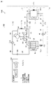
- FIG. 1 is a diagram showing a configuration of a refrigeration cycle device 1 according to a first embodiment. Note that FIG. 1 functionally shows the connection relationship and the arrangement configuration of each part in the refrigeration cycle apparatus 1, and does not necessarily show the arrangement in the physical space.
- the refrigeration cycle device 1 includes a cold heat source unit 5 constituting a refrigerant circuit 4.
- the cold heat source unit 5 is not particularly limited, but is generally referred to as an outdoor unit or an outdoor unit because it is often arranged outdoors or outdoors.
- the cold heat source unit 5 includes a cold heat source device 2 and a control device 6 for controlling each part included in the refrigerant circuit 4.
- the control device 6 includes a processor 61 and a memory 62.
- the processor 61 is an arithmetic unit that controls the refrigerant circuit 4 by executing various programs.
- the processor 61 is composed of, for example, at least one of a CPU (central processing unit), an FPGA (field programmable gate array), and a GPU (graphics processing unit).
- the processor 61 may be configured by a processing circuitry.
- the memory 62 is composed of a volatile memory such as DRAM (dynamic random access memory) and SRAM (static random access memory), or a non-volatile memory such as ROM (read only memory).
- the memory 62 may include an SSD (solid state drive) or an HDD (hard disk drive).
- the refrigerant circuit 4 is configured such that the cold heat source device 2 and the load device 3 are connected by each of the extension pipe 113 and the extension pipe 123.
- the cold heat source device 2 includes a port 111 and a port 112 for connecting to the load device 3.
- the load device 3 includes a port 121 and a port 122 for connecting to the cold heat source device 2.
- the port 112 of the cold heat source device 2 is connected to the port 121 of the load device 3 via the extension pipe 113.
- the port 111 of the cold heat source device 2 is connected to the port 122 of the load device 3 via the extension pipe 123.
- the cold heat source unit 5 is configured to be connectable to the load device 3 via the extension pipe 113 and the extension pipe 123.
- the load device 3 includes an indoor heat exchanger 70.
- the indoor heat exchanger 70 is connected to the port 121 of the load device 3 via the pipe 91.
- the indoor heat exchanger 70 is connected to the port 122 of the load device 3 via the pipe 92.
- the cold heat source device 2 includes a compressor 10, a four-way valve 20, an outdoor heat exchanger 30, and an expansion valve 40.
- the four-way valve 20 has a first port 21, a second port 22, a third port 23, and a fourth port 24.
- the first port 21 of the four-way valve 20 is connected to the suction port 11 of the compressor 10 via the pipe 85.
- the second port 22 of the four-way valve 20 is connected to the port 111 of the cold heat source device 2 via the pipe 86.
- the third port 23 of the four-way valve 20 is connected to the discharge port 12 of the compressor 10 via the pipe 81.
- the fourth port 24 of the four-way valve 20 is connected to the gas header 31 of the outdoor heat exchanger 30 via the pipe 82.
- the outdoor heat exchanger 30 is connected to the expansion valve 40 via the pipe 83.
- the expansion valve 40 is connected to the port 112 of the cold heat source device 2 via the pipe 84.
- the refrigeration cycle device 1 is controlled to one of a plurality of types of air conditioning modes including a cooling mode for cooling an indoor space to be air-conditioned and a heating mode for heating an indoor space.
- the communication state inside the four-way valve 20 is such that the first port 21 communicates with the second port 22 and the third port 23 communicates with the fourth port 24 according to the control of the control device 6 (control signal C2). It is controlled to the first state that communicates with. That is, in the cooling mode, the communication state inside the four-way valve 20 is controlled to the first state according to the control signal C2 of the control device 6, so that the suction port 11 of the compressor 10 communicates with the indoor heat exchanger 70. Moreover, the discharge port 12 of the compressor 10 communicates with the outdoor heat exchanger 30. As a result, the refrigerant circulates in the refrigerant circuit 4 in the order of the compressor 10, the outdoor heat exchanger 30, the expansion valve 40, and the indoor heat exchanger 70.
- the compressor 10 sucks the low-temperature low-pressure gas refrigerant flowing from the indoor heat exchanger 70 from the suction port 11 and compresses the sucked gas refrigerant to increase the pressure of the gas refrigerant.
- the compressor 10 discharges the high-temperature and high-pressure gas refrigerant obtained by compression to the gas header 31 of the outdoor heat exchanger 30 via the discharge port 12.
- the compressor 10 is configured to change the rotation speed during operation, stop, and operation according to the control of the control device 6 (control signal C1).
- the control device 6 arbitrarily changes the drive frequency of the compressor 10 by outputting the control signal C1 to the compressor 10.
- the compressor 10 changes the rotation speed according to the change in the drive frequency, thereby adjusting the circulation amount of the discharged refrigerant.
- Various types of compressors 10 can be adopted, and for example, scroll type, rotary type, screw type and the like can be adopted.
- the outdoor heat exchanger 30 functions as a condenser.
- the outdoor heat exchanger 30 receives the high-temperature and high-pressure gas refrigerant discharged from the compressor 10 by the gas header 31, and exchanges heat between the received high-temperature and high-pressure gas refrigerant with the outside air sucked from the outside by using the fan 32. Let me.
- the gas refrigerant radiated to the outside air by this heat exchange condenses inside the outdoor heat exchanger 30 and changes into a high-temperature and high-pressure liquid refrigerant.
- the high-temperature and high-pressure liquid refrigerant obtained by the outdoor heat exchanger 30 flows out to the expansion valve 40.
- the expansion valve 40 lowers the pressure of the high-temperature and high-pressure liquid refrigerant flowing from the outdoor heat exchanger 30.
- the expansion valve 40 causes the low-temperature low-pressure liquid refrigerant obtained by depressurization to flow out to the indoor heat exchanger 70.
- the expansion valve 40 is an electronic expansion valve whose opening degree is adjusted according to the control of the control device 6 (control signal C3).
- the indoor heat exchanger 70 functions as an evaporator.
- the indoor heat exchanger 70 exchanges heat between the low-temperature low-pressure liquid refrigerant flowing from the expansion valve 40 of the cold heat source device 2 and the air sucked from the indoor space using the fan 71.
- the liquid refrigerant absorbed from the air by this heat exchange evaporates inside the indoor heat exchanger 70 and changes into a low-temperature low-pressure gas refrigerant.
- the low-temperature low-pressure gas refrigerant obtained by the indoor heat exchanger 70 flows out to the compressor 10.
- the air absorbed by the gas refrigerant in the indoor heat exchanger 70 is sent back into the indoor space. As a result, the indoor space is cooled.
- the communication state inside the four-way valve 20 is such that the first port 21 communicates with the fourth port 24 and the second port 22 communicates with the third port 23 according to the control of the control device 6 (control signal C2). It is controlled to the second state that communicates with. That is, in the heating mode, the communication state inside the four-way valve 20 is controlled to the second state according to the control signal C2 of the control device 6, so that the suction port 11 of the compressor 10 communicates with the outdoor heat exchanger 30. Moreover, the discharge port 12 of the compressor 10 communicates with the indoor heat exchanger 70. As a result, the refrigerant circulates in the refrigerant circuit 4 in the order of the compressor 10, the indoor heat exchanger 70, the expansion valve 40, and the outdoor heat exchanger 30.
- the compressor 10 sucks the low-temperature low-pressure gas refrigerant flowing from the outdoor heat exchanger 30 from the suction port 11 and compresses the sucked gas refrigerant to increase the pressure of the gas refrigerant.
- the compressor 10 discharges the high-temperature and high-pressure gas refrigerant obtained by compression from the discharge port 12.
- the indoor heat exchanger 70 functions as a condenser.
- the indoor heat exchanger 70 exchanges heat between the high-temperature and high-pressure gas refrigerant discharged from the compressor 10 and the air sucked from the indoor space using the fan 71.
- the gas refrigerant radiated to the air by this heat exchange condenses inside the indoor heat exchanger 70 and changes into a high temperature and high pressure liquid refrigerant.
- the high-temperature and high-pressure liquid refrigerant obtained by the indoor heat exchanger 70 flows out to the expansion valve 40.
- the air absorbed from the gas refrigerant in the indoor heat exchanger 70 is sent back into the indoor space. This heats the interior space.
- the expansion valve 40 lowers the pressure of the high-temperature and high-pressure liquid refrigerant that has flowed in from the indoor heat exchanger 70.
- the expansion valve 40 causes the low-temperature low-pressure liquid refrigerant obtained by depressurization to flow out to the outdoor heat exchanger 30.
- the outdoor heat exchanger 30 functions as an evaporator.
- the outdoor heat exchanger 30 exchanges heat between the low-temperature low-pressure liquid refrigerant flowing from the expansion valve 40 and the outside air sucked from the outside by using the fan 32.
- the liquid refrigerant absorbed from the outside air by this heat exchange evaporates inside the outdoor heat exchanger 30 and changes into a low-temperature low-pressure gas refrigerant.
- the low-temperature low-pressure gas refrigerant obtained by the outdoor heat exchanger 30 flows out to the compressor 10.
- the refrigerating machine oil circulates in the refrigerant circuit 4 together with the refrigerant.
- the refrigerating machine oil plays a role of lubricating action, sealing action, rust preventive action, etc., and is required for driving the compressor 10.
- the zero penetration rate is known as the minimum flow velocity of the gas refrigerant required for the gas refrigerant to flow in the gas header 31.
- the refrigerating machine oil flows in the gas header 31 together with the gas refrigerant, but when the flow velocity of the gas refrigerant does not exceed the zero penetration rate, the refrigerating machine oil is also in the gas header 31 together with the gas refrigerant. Stay in.
- the air conditioning load becomes smaller, so that the drive frequency of the compressor 10 becomes lower.
- the compressor 10 may continue to be driven at a frequency lower than the frequency during normal operation at night in the middle period (spring, autumn, etc.) when the air conditioning load is small.
- the compressor 10 is driven at such a low frequency, the flow velocity of the gas refrigerant flowing into the gas header 31 is unlikely to exceed the zero penetration rate, and the refrigerating machine oil tends to stay in the gas header 31.
- the flow velocity of the gas refrigerant flowing into the gas header 31 does not easily exceed the zero penetration rate, and the refrigerating machine oil tends to stay in the gas header 31. Become. If the refrigerating machine oil stays in the gas header 31, the refrigerating machine oil in the compressor 10 is depleted, and there is a possibility that the compressor 10 may have a problem such as shaft galling.
- a refueling operation such as temporarily increasing the drive frequency of the compressor 10 is performed.
- the indoor space may be too cold due to the cold air sent from the indoor heat exchanger 70 to the indoor space. be.
- the cooling mode when the oil return operation is performed with the fan 71 of the indoor heat exchanger 70 stopped, the fan 71 of the indoor heat exchanger 70 is stopped while the compressor is stopped. It is unnatural because 10 works. Further, in the oil return operation, since the drive frequency of the compressor 10 is increased, the power consumption is increased by that amount, and it becomes difficult to save energy.
- the cold heat source unit 5 further includes an oil return path for returning the refrigerating machine oil from the gas header 31 to the compressor 10 in order to efficiently return the oil in consideration of the driving state of the compressor 10.
- the gas header 31 is connected to the suction port 11 of the compressor 10 via the pipe 87, the pipe 88, the pipe 89, and the pipe 90.
- the oil return path is composed of these pipes 87 to 90.
- the cold heat source unit 5 includes a check valve 130, an oil return adjusting unit 50, and a capillary tube 60 in the oil return path.
- the check valve 130 is connected to the gas header 31 via the pipe 87.
- the oil return adjusting unit 50 is connected to the check valve 130 via the pipe 88.
- the capillary tube 60 is connected to the oil return adjusting unit 50 via the pipe 89.
- the suction port 11 of the compressor 10 is connected to the capillary tube 60 via the pipe 90.
- the oil return adjusting unit 50 adjusts the flow rates of the refrigerant and the refrigerating machine oil flowing through the oil return path according to the control of the control device 6 (control signal C4).
- the oil return adjusting unit 50 according to the first embodiment is an on-off valve that can be switched between an open state and a closed state according to the control of the control device 6 (control signal C4).
- the capillary tube 60 adjusts the flow rate of the refrigerant by the pressure difference.
- the check valve 130 allows the refrigerant and refrigerating machine oil to flow from the gas header 31 to the suction port 11 of the compressor 10 through the oil return path, while allowing the refrigerant and refrigerating machine oil to flow through the oil return path to the suction port 11 of the compressor 10.
- the check valve 130 is provided not only between the gas header 31 and the oil return adjusting unit 50, but also between the oil return adjusting unit 50 and the capillary tube 60, or between the capillary tube 60 and the compressor 10. May be done.
- the control device 6 controls the oil return adjusting unit 50 to a closed state or an open state depending on whether or not the compressor 10 is operating at a low frequency. Specifically, the control device 6 controls the oil return adjusting unit 50 to a closed state or an open state depending on whether or not the compressor 10 is driven at a frequency equal to or higher than a predetermined threshold value. As the threshold frequency, a frequency may be set so that the flow velocity of the gas refrigerant flowing into the gas header 31 does not exceed the zero penetration rate.
- oil return control such control by the control device 6 is referred to as oil return control.
- the control device 6 makes it difficult for the refrigerating machine oil to stay in the gas header 31, so that the refrigerating machine oil does not flow through the oil return path. Control to the closed state.
- the compressor 10 when the compressor 10 is driven at a frequency lower than the threshold value, the refrigerating machine oil tends to stay in the gas header 31, so that the refrigerating machine oil flows through the oil return path. Is controlled to the open state.
- the oil return adjusting unit 50 When the oil return adjusting unit 50 is controlled to be in the open state, the oil return path is opened, so that the refrigerant and refrigerating machine oil flowing out of the gas header 31 flow through the oil return path and are returned to the compressor 10.
- the gas refrigerant flowing through the oil return path is returned to the compressor 10 in a state where the pressure is lowered.
- control device 6 determines whether or not the compressor 10 is driven at a frequency equal to or higher than the threshold value, and if the compressor 10 is driven at a frequency equal to or higher than the threshold value, returns. By opening the oil path, the refrigerating machine oil is returned to the compressor 10.
- control device 6 determines the value of the drive frequency of the compressor 10 in determining whether or not the compressor 10 is operating at a low frequency, but the compressor 10 is operating at a low frequency.
- other values may be determined in order to improve the determination accuracy of whether or not the compressor 10 is performed.
- the refrigerant circuit 4 further includes a temperature sensor 101, a temperature sensor 102, and a temperature sensor 103.
- the temperature sensor 101 measures the temperature of the air sucked from the indoor space (hereinafter, also referred to as “suction temperature”) using the fan 71 of the indoor heat exchanger 70, and outputs the measured value T1 to the control device 6. ..
- the temperature sensor 102 measures the saturation temperature of the refrigerant in the indoor heat exchanger 70 (evaporation temperature in the case of cooling), and outputs the measured value T2 to the control device 6.
- the temperature sensor 103 measures the saturation temperature of the refrigerant in the outdoor heat exchanger 30 (condensation temperature in the case of cooling), and outputs the measured value T3 to the control device 6.
- the control device 6 is not limited to the suction temperature in the indoor heat exchanger 70, and the temperature measured by the temperature sensor provided in the indoor space may be used instead of the suction temperature (measured value T1).
- the air conditioning load becomes smaller, so that the drive frequency of the compressor 10 becomes lower.
- the difference between the saturation pressure of the refrigerant in the indoor heat exchanger 70 and the saturation pressure of the refrigerant in the outdoor heat exchanger 30 becomes small, and further, the saturation of the refrigerant in the indoor heat exchanger 70 becomes small.
- the difference between the temperature and the saturation temperature of the refrigerant in the outdoor heat exchanger 30 becomes small.
- control device 6 determines the compressor 10 based on the saturation temperature of the refrigerant in the indoor heat exchanger 70 specified by the measured value T2 and the saturation temperature of the refrigerant in the outdoor heat exchanger 30 specified by the measured value T3. Determines whether or not is driven at a frequency below the threshold value, that is, whether or not the compressor 10 is operating at a low frequency.
- the difference between the saturation temperature of the refrigerant in the indoor heat exchanger 70 specified by the measured value T2 and the saturation temperature of the refrigerant in the outdoor heat exchanger 30 specified by the measured value T3 is predetermined.
- the temperature is lower than the specified reference temperature, it is determined that the compressor 10 is driven at a frequency lower than the threshold value.
- the control device 6 in determining whether or not the compressor 10 is operating at a low frequency, has an indoor heat exchanger in addition to a function (means) for determining the value of the drive frequency of the compressor 10. It may have a function (means) for determining the difference between the saturation temperature of the refrigerant in 70 and the saturation temperature of the refrigerant in the outdoor heat exchanger 30.
- control device 6 is set by the compressor 10 based on the saturation pressure corresponding to the saturation temperature of the refrigerant in the indoor heat exchanger 70 and the saturation pressure corresponding to the saturation temperature of the refrigerant in the outdoor heat exchanger 30. It is determined whether or not the compressor 10 is driven at a frequency lower than the threshold value, that is, whether or not the compressor 10 is operating at a low frequency.
- the control device 6 calculates the saturation pressure of the refrigerant in the indoor heat exchanger 70 based on the saturation temperature specified by the measured value T2, and the outdoor heat exchanger is based on the saturation temperature specified by the measured value T3.
- the saturation pressure of the refrigerant at 30 is calculated.
- the compressor 10 when the difference between the saturation pressure of the refrigerant in the indoor heat exchanger 70 and the saturation pressure of the refrigerant in the outdoor heat exchanger 30 is less than a predetermined reference pressure, the compressor 10 has a threshold. Judge that it is driven at a frequency less than the value.
- the control device 6 in determining whether or not the compressor 10 is operating at a low frequency, has an indoor heat exchanger in addition to a function (means) for determining the value of the drive frequency of the compressor 10. It may have a function (means) for determining the difference between the saturation pressure of the refrigerant in 70 and the saturation pressure of the refrigerant in the outdoor heat exchanger 30.
- the control device 6 has a function (means) for determining the value of the drive frequency of the compressor 10, and determines the difference between the saturation temperature of the refrigerant in the indoor heat exchanger 70 and the saturation temperature of the refrigerant in the outdoor heat exchanger 30. Selectively select at least one of the function (means) and the function (means) for determining the difference between the saturation pressure of the refrigerant in the indoor heat exchanger 70 and the saturation pressure of the refrigerant in the outdoor heat exchanger 30. You may be prepared.
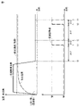
- FIG. 2 is a timing chart showing the timing of oil return control in the cooling mode for the refrigeration cycle device 1 according to the first embodiment.
- a first timing chart showing the suction temperature of air sucked from the indoor space, a set temperature in the cooling mode, and a drive frequency of the compressor 10, and a second timing chart showing the opening and closing of the oil return adjusting unit 50 are shown.
- the vertical axis represents temperature and drive frequency
- the horizontal axis represents time.
- the vertical axis represents the opening and closing of the oil return adjusting unit 50
- the horizontal axis represents time.
- the horizontal axis (time axis) in the second timing chart corresponds to the horizontal axis (time axis) in the first timing chart.
- the suction temperature of the indoor air gradually decreases due to the drive of the compressor 10 in the cooling mode, and when the suction temperature eventually drops to near the set temperature, the drive frequency of the compressor 10 gradually decreases. Eventually, the drive frequency becomes less than the threshold value (timing t0).
- the threshold value (timing t0)
- the compressor 10 continues to be driven at a frequency lower than the threshold value, the flow velocity of the gas refrigerant becomes difficult to exceed the zero penetration rate, and the refrigerating machine oil stays in the gas header 31.
- the control device 6 After driving the compressor 10 at a frequency below the threshold value, the control device 6 keeps the oil return adjusting unit 50 in a closed state for a predetermined first period ( ⁇ t1), and then keeps the oil return adjusting unit 50 in a closed state. 50 is switched from the closed state to the open state (timing t1). As a result, the oil return path is opened, so that the refrigerating machine oil is returned to the compressor 10 from the gas header 31 on the high pressure side to the suction port 11 of the compressor 10 on the low pressure side via the oil return path.
- the first period ( ⁇ t1) from the time when the compressor 10 starts to drive at a frequency below the threshold value (in other words, from the time when the refrigerating machine oil starts to stay in the gas header 31) until a predetermined amount or more of the refrigerating machine oil stays. It is a prediction period and can be set to any period such as 2 hours.
- the first period ( ⁇ t1) can be set to the same period in the timing charts shown in FIGS. 3, 4, and 6 to 8, which will be described later.
- the control device 6 After switching the oil return adjusting unit 50 from the closed state to the open state, the control device 6 keeps the oil return adjusting unit 50 in the open state for a predetermined second period ( ⁇ t2), and then adjusts the oil return again.
- the unit 50 is switched from the open state to the closed state (timing t2).
- the second period ( ⁇ t2) is a predicted period from when the oil return path is opened until a predetermined amount or more of the refrigerating machine oil staying in the gas header 31 returns to the compressor 10, for example, in an arbitrary period such as 10 minutes. Can be set.
- the second period ( ⁇ t2) can be set to the same period in the timing charts shown in FIGS. 3, 4, and 6 to 8, which will be described later.
- the control device 6 After switching the oil return adjusting unit 50 from the open state to the closed state, the control device 6 keeps the oil return adjusting unit 50 in the closed state for a predetermined first period ( ⁇ t1), and then adjusts the oil return again.
- the unit 50 is switched from the closed state to the open state (timing t3).
- the oil return path is opened again, so that the refrigerating machine oil is returned to the compressor 10 from the gas header 31 on the high pressure side to the suction port 11 of the compressor 10 on the low pressure side via the oil return path.
- the control device 6 After switching the oil return adjusting unit 50 from the closed state to the open state, the control device 6 keeps the oil return adjusting unit 50 in the open state for a predetermined second period ( ⁇ t2), and then adjusts the oil return again.
- the unit 50 is switched from the open state to the closed state (timing t4). As a result, the oil return path is closed again, so that the refrigerant circulates again in the refrigerant circuit 4 without passing through the oil return path.
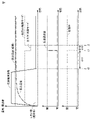
- FIG. 3 is a timing chart showing the timing of oil return control in the heating mode for the refrigeration cycle device 1 according to the first embodiment.
- a first timing chart showing the suction temperature of air sucked from the indoor space, a set temperature in the heating mode, and a drive frequency of the compressor 10, and a second timing chart showing the opening and closing of the oil return adjusting unit 50 are shown.
- the vertical axis represents temperature and drive frequency
- the horizontal axis represents time.
- the vertical axis represents the opening and closing of the oil return adjusting unit 50
- the horizontal axis represents time.
- the horizontal axis (time axis) in the second timing chart corresponds to the horizontal axis (time axis) in the first timing chart.
- the suction temperature of the room air gradually rises by driving the compressor 10 in the heating mode, and when the suction temperature eventually rises to near the set temperature, the drive frequency of the compressor 10 gradually drops. Eventually, the drive frequency becomes less than the threshold value (timing t0).
- the threshold value (timing t0)
- the compressor 10 continues to be driven at a frequency lower than the threshold value, the flow velocity of the gas refrigerant becomes difficult to exceed the zero penetration rate, and the refrigerating machine oil stays in the gas header 31.
- the control device 6 After driving the compressor 10 at a frequency below the threshold value, the control device 6 keeps the oil return adjusting unit 50 in a closed state for a predetermined first period ( ⁇ t1), and then keeps the oil return adjusting unit 50 in a closed state. 50 is switched from the closed state to the open state (timing t1). As a result, the oil return path is opened, so that the refrigerating machine oil is returned to the compressor 10 from the gas header 31 to the suction port 11 of the compressor 10 via the oil return path.
- the control device 6 After switching the oil return adjusting unit 50 from the closed state to the open state, the control device 6 keeps the oil return adjusting unit 50 in the open state for a predetermined second period ( ⁇ t2), and then adjusts the oil return again.
- the unit 50 is switched from the open state to the closed state (timing t2). As a result, the oil return path is closed again, so that the refrigerant circulates again in the refrigerant circuit 4 without passing through the oil return path.
- the control device 6 After switching the oil return adjusting unit 50 from the open state to the closed state, the control device 6 keeps the oil return adjusting unit 50 in the closed state for a predetermined first period ( ⁇ t1), and then adjusts the oil return again.
- the unit 50 is switched from the closed state to the open state (timing t3).
- the oil return path is opened again, so that the refrigerating machine oil is returned to the compressor 10 from the gas header 31 to the suction port 11 of the compressor 10 via the oil return path.
- the control device 6 After switching the oil return adjusting unit 50 from the closed state to the open state, the control device 6 keeps the oil return adjusting unit 50 in the open state for a predetermined second period ( ⁇ t2), and then adjusts the oil return again.
- the unit 50 is switched from the open state to the closed state (timing t4). As a result, the oil return path is closed again, so that the refrigerant circulates again in the refrigerant circuit 4 without passing through the oil return path.
- the control device 6 prevents the refrigerating machine oil from flowing through the oil return path when the compressor 10 is driven at a frequency equal to or higher than the threshold value.
- the oil return adjustment unit 50 is kept closed, and when the compressor 10 is driven at a frequency below the threshold value, the oil return adjustment unit 50 is opened so that the refrigerating machine oil flows through the oil return path. maintain.
- the refrigerating cycle device 1 returns the oil only when the compressor 10 is driven at a frequency less than the threshold value, that is, when the refrigerating machine oil tends to stay in the gas header 31, so that the compressor 10 is driven.
- the oil can be returned efficiently in consideration of the condition.
- the control device 6 alternately repeats a state in which the refrigerating machine oil flows in the oil return path and a state in which the refrigerating machine oil does not flow in the oil return path when the compressor 10 is driven at a frequency below the threshold value.
- the oil return adjusting unit 50 is repeatedly switched between the open state and the closed state.
- the refrigerating cycle device 1 can maintain a balance between the period for returning oil and the period for circulating the refrigerant in the refrigerant circuit 4 in a state where the compressor 10 is driven at a frequency lower than the threshold value. can.
- the control device 6 may perform oil return control as shown in FIG.
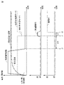
- FIG. 4 is a timing chart showing the timing of oil return control in the heating mode for the refrigeration cycle device 1 according to the modified example of the first embodiment.
- the first timing chart showing the suction temperature of the air sucked from the interior space, the set temperature in the heating mode, the drive frequency of the compressor 10, and the switching of the four-way valve 20, and the opening / closing of the oil return adjusting unit 50 are shown.
- a second timing chart showing the opening and closing of the expansion valve 40 and a third timing chart showing the opening and closing of the expansion valve 40 are shown.
- the vertical axis represents temperature and drive frequency
- the horizontal axis represents time.
- the vertical axis represents the opening and closing of the oil return adjusting unit 50, and the horizontal axis represents time.
- the vertical axis represents the opening and closing of the expansion valve 40, and the horizontal axis represents time.
- the horizontal axis (time axis) in each of the second timing chart and the third timing chart corresponds to the horizontal axis (time axis) in the first timing chart.
- the suction temperature of the room air gradually rises due to the drive of the compressor 10 in the heating mode, and when the suction temperature eventually rises to near the set temperature, the drive frequency of the compressor 10 gradually drops. Eventually, the drive frequency of the compressor 10 becomes less than the threshold value (timing t0).
- the threshold value (timing t0)
- the flow velocity of the gas refrigerant becomes difficult to exceed the zero penetration rate, and the refrigerating machine oil stays in the gas header 31.
- the control device 6 drives the compressor 10 at a frequency lower than the threshold value, and then keeps the oil return adjusting unit 50 in a closed state for a predetermined first period ( ⁇ t1). After that, the control device 6 switches the internal communication state of the four-way valve 20 from the second state in the heating mode to the first state in the cooling mode, and switches the oil return adjusting unit 50 from the closed state to the open state. Further, the expansion valve 40 is switched from the open state to the closed state (timing t1). As a result, the oil return path is maintained in an open state while the gas header 31 is on the high pressure side and the suction port 11 of the compressor 10 is on the low pressure side. Therefore, the compressor 10 on the low pressure side is maintained from the gas header 31 on the high pressure side.
- the refrigerating machine oil is returned to the compressor 10 via the oil return path to the suction port 11 of the above. Further, since the expansion valve 40 is maintained in the closed state, it is possible to prevent the refrigerant and the refrigerating machine oil from flowing from the outdoor heat exchanger 30 to the indoor heat exchanger 70 as much as possible.
- the control device 6 After switching the oil return adjusting unit 50 from the closed state to the open state, the control device 6 maintains the oil return adjusting unit 50 in the open state for a predetermined second period ( ⁇ t2). After that, the control device 6 switches the internal communication state of the four-way valve 20 from the first state in the cooling mode to the second state in the heating mode, and switches the oil return adjusting unit 50 from the open state to the closed state. Further, the expansion valve 40 is switched from the closed state to the open state (timing t2). As a result, the communication state inside the four-way valve 20 is maintained in the second state in the heating mode, and the oil return path is closed again with the expansion valve 40 kept in the open state. The refrigerant circulates again in the refrigerant circuit 4 without passing through.
- the control device 6 sets the four-way valve 20 in the heating mode when the compressor 10 is driven at a frequency equal to or higher than the threshold value.
- the expansion valve 40 is switched from the open state to the closed state while switching from the second state of the above to the first state in the cooling mode, and the oil return adjusting unit 50 is maintained in the open state so that the refrigerating machine oil flows through the oil return path.
- the refrigerating cycle device 1 temporarily sets the gas header 31 to the high pressure side while setting the suction port 11 of the compressor 10 to the low pressure side. The refrigerating machine oil can be efficiently returned to the compressor 10 via the oil return path.
- FIG. 5 is a diagram showing the configuration of the refrigeration cycle apparatus 1000 according to the second embodiment. In the following, only the part of the refrigerating cycle device 1000 that is different from the refrigerating cycle device 1 according to the first embodiment will be described.
- the cold heat source device 200 of the cold heat source unit 500 is the oil return adjusting unit 50 (open) provided in the cold heat source device 2 according to the first embodiment.
- An on-off valve that can be switched between a state and a closed state) and an oil return adjusting unit 150 are provided in place of the capillary tube 60.
- the oil return adjusting unit 150 is an electronic expansion valve whose opening degree is adjusted according to the control of the control device 600 (control signal C5).
- the control device 600 controls the opening degree of the oil return adjusting unit 150 according to whether or not the compressor 10 is driven at a frequency equal to or higher than a predetermined threshold value. Specifically, the control device 600 returns the refrigerating machine oil so that it does not flow in the oil return path because the refrigerating machine oil is unlikely to stay in the gas header 31 when the compressor 10 is driven at a frequency equal to or higher than the threshold value. The opening degree of the oil adjusting unit 150 is reduced.
- control device 600 when the compressor 10 is driven at a frequency lower than the threshold value, the refrigerating machine oil tends to stay in the gas header 31, so that the refrigerating machine oil flows through the oil return path. Increase the opening of.
- FIG. 6 is a timing chart showing the timing of oil return control in the cooling mode for the refrigeration cycle apparatus 1000 according to the second embodiment.
- a first timing chart showing the suction temperature of air sucked from the indoor space, a set temperature in the cooling mode, and a drive frequency of the compressor 10, and a second timing chart showing the opening and closing of the oil return adjusting unit 150 are shown.
- the vertical axis represents temperature and drive frequency
- the horizontal axis represents time.
- the vertical axis represents the opening and closing of the oil return adjusting unit 150
- the horizontal axis represents time.
- the horizontal axis (time axis) in the second timing chart corresponds to the horizontal axis (time axis) in the first timing chart.
- the suction temperature of the indoor air gradually decreases due to the drive of the compressor 10 in the cooling mode, and when the suction temperature eventually drops to near the set temperature, the drive frequency of the compressor 10 gradually decreases. Eventually, the drive frequency becomes less than the threshold value (timing t0).
- the threshold value (timing t0)
- the compressor 10 continues to be driven at a frequency lower than the threshold value, the flow velocity of the gas refrigerant becomes difficult to exceed the zero penetration rate, and the refrigerating machine oil stays in the gas header 31.
- the control device 600 drives the compressor 10 at a frequency less than the threshold value, and then gradually opens the oil return adjusting unit 150 to a predetermined first opening.
- the opening degree of the oil return adjusting unit 150 reaches the first opening degree by the time when the predetermined first period ( ⁇ t1) elapses from the timing t0 (timing t1).
- ⁇ t1 the predetermined first period
- timing t0 timing t1
- the oil return path is opened at the first opening, so that the flow rate is adjusted from the gas header 31 on the high pressure side to the suction port 11 of the compressor 10 on the low pressure side via the oil return path at the first opening.
- the refined refrigerating machine oil is returned to the compressor 10.
- the control device 600 After opening the oil return adjusting unit 150 at the first opening, the control device 600 maintains the opening of the oil return adjusting unit 150 at the first opening for a predetermined second period ( ⁇ t2), and then maintains the opening of the oil return adjusting unit 150 at the first opening.
- the oil return adjusting unit 150 is gradually closed again (timing t2). As a result, the oil return path is closed again, so that the refrigerant circulates again in the refrigerant circuit 4 without passing through the oil return path.
- the control device 600 keeps the oil return adjusting unit 150 in the closed state, and then gradually opens the oil return adjusting unit 150 again to a predetermined first opening.
- the opening degree of the oil return adjusting unit 150 reaches the first opening degree by the time when the predetermined first period ( ⁇ t1) elapses from the timing t2 (timing t3).
- the oil return path is opened again at the first opening, so that the flow rate from the gas header 31 on the high pressure side to the suction port 11 of the compressor 10 on the low pressure side via the oil return path at the first opening.
- the adjusted refrigerating machine oil is returned to the compressor 10.
- the control device 600 After opening the oil return adjusting unit 150 at the first opening, the control device 600 maintains the opening of the oil return adjusting unit 150 at the first opening for a predetermined second period ( ⁇ t2), and then maintains the opening of the oil return adjusting unit 150 at the first opening.
- the oil return adjusting unit 150 is gradually closed again (timing t4). As a result, the oil return path is closed again, so that the refrigerant circulates again in the refrigerant circuit 4 without passing through the oil return path.
- FIG. 7 is a timing chart showing the timing of oil return control in the heating mode for the refrigeration cycle device 1000 according to the second embodiment.
- a first timing chart showing the suction temperature of air sucked from the indoor space, a set temperature in the heating mode, and a drive frequency of the compressor 10, and a second timing chart showing the opening and closing of the oil return adjusting unit 150 are shown.
- the vertical axis represents temperature and drive frequency
- the horizontal axis represents time.
- the vertical axis represents the opening and closing of the oil return adjusting unit 150
- the horizontal axis represents time.
- the horizontal axis (time axis) in the second timing chart corresponds to the horizontal axis (time axis) in the first timing chart.
- the suction temperature of the room air gradually rises due to the drive of the compressor 10 in the heating mode, and when the suction temperature eventually rises to near the set temperature, the drive frequency of the compressor 10 gradually drops. Eventually, the drive frequency becomes less than the threshold value (timing t0).
- the threshold value (timing t0)
- the compressor 10 continues to be driven at a frequency lower than the threshold value, the flow velocity of the gas refrigerant becomes difficult to exceed the zero penetration rate, and the refrigerating machine oil stays in the gas header 31.
- the control device 600 drives the compressor 10 at a frequency less than the threshold value, and then gradually opens the oil return adjusting unit 150 to a predetermined first opening.
- the opening degree of the oil return adjusting unit 150 reaches the second opening degree by the time when the predetermined first period ( ⁇ t1) elapses from the timing t0 (timing t1).
- ⁇ t1 predetermined first period
- timing t0 timing t1
- the oil return path is opened at the second opening, so that the refrigerating machine oil whose flow rate is adjusted at the second opening is compressed from the gas header 31 to the suction port 11 of the compressor 10 via the oil return path. Returned to machine 10.
- the second opening in the heating mode is set to be larger than the first opening in the cooling mode, whereby the gas header 31 and the suction port 11 of the compressor 10 have the same or substantially the same pressure (low pressure). Even so, the refrigerating machine oil is returned to the compressor 10 at a larger flow rate than in the cooling mode.
- the control device 600 After opening the oil return adjusting unit 150 at the second opening, the control device 600 maintains the opening of the oil return adjusting unit 150 at the second opening for a predetermined second period ( ⁇ t2), and then maintains the opening of the oil return adjusting unit 150 at the second opening.
- the oil return adjusting unit 150 is gradually closed again (timing t2). As a result, the oil return path is closed again, so that the refrigerant circulates again in the refrigerant circuit 4 without passing through the oil return path.
- the control device 600 keeps the oil return adjusting unit 150 in the closed state, and then gradually opens the oil return adjusting unit 150 again to a predetermined second opening.
- the opening degree of the oil return adjusting unit 150 reaches the second opening degree by the time when the predetermined first period ( ⁇ t1) elapses from the timing t2 (timing t3).
- ⁇ t1 predetermined first period
- timing t2 timing t3
- the oil return path is opened again at the second opening, so that the flow rate from the gas header 31 on the high pressure side to the suction port 11 of the compressor 10 on the low pressure side is passed through the oil return path at the second opening.
- the adjusted refrigerating machine oil is returned to the compressor 10.
- the control device 600 After opening the oil return adjusting unit 150 at the second opening, the control device 600 maintains the opening of the oil return adjusting unit 150 at the second opening for a predetermined second period ( ⁇ t2), and then maintains the opening of the oil return adjusting unit 150 at the second opening.
- the oil return adjusting unit 150 is gradually closed again (timing t4). As a result, the oil return path is closed again, so that the refrigerant circulates again in the refrigerant circuit 4 without passing through the oil return path.
- the control device 600 prevents the refrigerating machine oil from flowing through the oil return path when the compressor 10 is driven at a frequency equal to or higher than the threshold value.
- the oil return adjusting unit 150 is kept closed, and when the compressor 10 is driven at a frequency below the threshold value, the oil return adjusting unit 150 is opened so that the refrigerating machine oil flows through the oil return path. maintain.
- the refrigerating cycle device 1000 returns the oil only when the compressor 10 is driven at a frequency less than the threshold value, that is, when the refrigerating machine oil tends to stay in the gas header 31, so that the compressor 10 is driven.
- the oil can be returned efficiently in consideration of the condition.
- the control device 600 alternately repeats a state in which the refrigerating machine oil flows in the oil return path and a state in which the refrigerating machine oil does not flow in the oil return path when the compressor 10 is driven at a frequency below the threshold value.
- the oil return adjusting unit 150 is repeatedly switched between the open state and the closed state.
- the refrigerating cycle apparatus 1000 can maintain a balance between the period for returning oil and the period for circulating the refrigerant in the refrigerant circuit 4 in a state where the compressor 10 is driven at a frequency less than the threshold value. can.
- the oil return adjusting unit 150 is an electronic expansion valve whose opening degree is adjusted according to the control of the control device 600. Thereby, the refrigerating cycle device 1000 can adjust the opening degree of the oil return path according to whether it is in the cooling mode or the heating mode by adjusting the opening degree of the oil return adjusting unit 150. .. Further, unlike the refrigeration cycle device 1 according to the first embodiment, it is not necessary to provide the capillary tube 60, so that the manufacturing cost can be suppressed.
- the oil return adjusting unit 150 When the oil return adjusting unit 150 is controlled to be in the open state in the heating mode as shown in FIG. 7, the oil return is returned because the gas header 31 and the suction port 11 of the compressor 10 have the same or substantially the same pressure (low pressure). Even if the opening degree of the adjusting unit 150 is adjusted, the amount of refrigerating machine oil returning to the compressor 10 via the oil return path may not be sufficient. Therefore, in the refrigerating cycle device 1000 according to the modified example, the control device 600 may perform oil return control as shown in FIG.
- FIG. 8 is a timing chart showing the timing of oil return control in the heating mode for the refrigeration cycle device 1000 according to the modified example of the second embodiment.
- the first timing chart showing the suction temperature of the air sucked from the interior space, the set temperature in the heating mode, the drive frequency of the compressor 10, and the switching of the four-way valve 20, and the opening / closing of the oil return adjusting unit 150 are shown.
- a second timing chart showing the opening and closing of the expansion valve 40 and a third timing chart showing the opening and closing of the expansion valve 40 are shown.
- the vertical axis represents temperature and drive frequency
- the horizontal axis represents time.
- the vertical axis represents the opening and closing of the oil return adjusting unit 150, and the horizontal axis represents time.
- the vertical axis represents the opening and closing of the expansion valve 40, and the horizontal axis represents time.
- the horizontal axis (time axis) in each of the second timing chart and the third timing chart corresponds to the horizontal axis (time axis) in the first timing chart.
- the suction temperature of the room air gradually rises due to the drive of the compressor 10 in the heating mode, and when the suction temperature eventually rises to near the set temperature, the drive frequency of the compressor 10 gradually drops. Eventually, the drive frequency of the compressor 10 becomes less than the threshold value (timing t0).
- the threshold value (timing t0)
- the flow velocity of the gas refrigerant becomes difficult to exceed the zero penetration rate, and the refrigerating machine oil stays in the gas header 31.
- the control device 600 After driving the compressor 10 at a frequency lower than the threshold value, the control device 600 switches the communication state inside the four-way valve 20 from the second state in the heating mode to the first state in the cooling mode, and at the same time, The oil return adjusting unit 50 is gradually opened to a predetermined first opening, and the expansion valve 40 is further switched from the open state to the closed state (timing t1).
- the opening degree of the oil return adjusting unit 150 reaches the second opening degree by the time when the predetermined first period ( ⁇ t1) elapses from the timing t0 (timing t1). As a result, the oil return path is maintained in an open state while the gas header 31 is on the high pressure side and the suction port 11 of the compressor 10 is on the low pressure side.
- the compressor 10 on the low pressure side is maintained from the gas header 31 on the high pressure side.
- the refrigerating machine oil is returned to the compressor 10 via the oil return path to the suction port 11 of the above. Further, since the expansion valve 40 is maintained in the closed state, it is possible to prevent the refrigerant and the refrigerating machine oil from flowing from the outdoor heat exchanger 30 to the indoor heat exchanger 70 as much as possible.
- the control device 600 After opening the oil return adjusting unit 150 at the second opening, the control device 600 maintains the opening of the oil return adjusting unit 150 at the second opening for a predetermined second period ( ⁇ t2). After that, the control device 600 switches the internal communication state of the four-way valve 20 from the first state in the cooling mode to the second state in the heating mode, gradually closes the oil return adjusting unit 150, and further, the expansion valve. The 40 is switched from the closed state to the open state (timing t2). As a result, the communication state inside the four-way valve 20 is maintained in the second state in the heating mode, and the oil return path is closed again with the expansion valve 40 kept in the open state. The refrigerant circulates again in the refrigerant circuit 4 without passing through.
- the control device 600 sets the four-way valve 20 in the heating mode when the compressor 10 is driven at a frequency equal to or higher than the threshold value.
- the expansion valve 40 is switched from the open state to the closed state while switching from the second state of the above to the first state in the cooling mode, and the oil return adjusting unit 150 is maintained in the open state so that the refrigerating machine oil flows through the oil return path.
- the refrigerating cycle device 1000 temporarily sets the gas header 31 to the high pressure side and the suction port 11 of the compressor 10 to the low pressure side even when the refrigerating machine oil stays in the gas header 31 in the heating mode.
- the refrigerating machine oil can be efficiently returned to the compressor 10 via the oil return path.
- the present disclosure relates to the cold heat source units 5,500 which can be connected to the indoor heat exchanger 70 and constitute the refrigerant circuit 4.
- the cold heat source units 5, 500 have a compressor 10, an outdoor heat exchanger 30 having a gas header 31, an oil return path (pipes 87 to 90) for returning refrigerating machine oil from the gas header 31 to the compressor 10, and an oil return path.
- the oil return adjusting units 50 and 150 for adjusting the flow rate of the flowing refrigerating machine oil and the control devices 6, 600 for controlling the refrigerant circuit 4 are provided.
- the control devices 6 and 600 control the oil return adjusting units 50 and 150 so that the refrigerating machine oil does not flow in the oil return path when the compressor 10 is driven at a frequency equal to or higher than the threshold value, and the compressor 10 controls the compressor 10. Controls the oil return adjusting units 50 and 150 so that the refrigerating machine oil flows through the oil return path when the oil is driven at a frequency below the threshold value.
- the cold heat source units 5,500 return oil only when the compressor 10 is driven at a frequency below the threshold value, that is, when the refrigerating machine oil tends to stay in the gas header 31. Therefore, the oil can be efficiently returned in consideration of the driving state of the compressor 10.
- control devices 6, 600 determine a state in which the refrigerating machine oil flows in the oil return path and a state in which the refrigerating machine oil does not flow in the oil return path when the compressor 10 is driven at a frequency below the threshold value.
- the oil return adjusting units 50 and 150 are controlled so as to repeat alternately.
- the cold heat source units 5,500 circulate the refrigerant in the refrigerant circuit 4 and the period for returning oil in a state where the compressor 10 is driven at a frequency below the threshold value. You can keep the balance with the period.
- the cold heat source units 5,500 further include a four-way valve 20 and an expansion valve 40 provided in the path between the outdoor heat exchanger 30 and the indoor heat exchanger 70.
- the communication state inside the four-way valve 20 is the first state in which the suction port 11 of the compressor 10 communicates with the indoor heat exchanger 70 and the discharge port 12 of the compressor 10 communicates with the outdoor heat exchanger 30 and the compressor.
- the suction port 11 of 10 communicates with the outdoor heat exchanger 30, and the discharge port 12 of the compressor 10 communicates with the indoor heat exchanger 70.
- the control devices 6, 600 switch the four-way valve 20 from the second state to the first state and expand when the four-way valve 20 is in the second state and the compressor 10 is driven at a frequency below the threshold value.
- the valve 40 is switched from the open state to the closed state, and the oil return adjusting units 50 and 150 are controlled so that the refrigerating machine oil flows in the oil return path.
- the cold heat source unit 5,500 switches the communication state inside the four-way valve 20 from the second state to the first state even when the refrigerating machine oil stays in the gas header 31 in the heating mode.
- the refrigerating machine oil can be efficiently returned to the compressor 10 via the oil return path.
- control devices 6 and 600 drive the compressor 10 at a frequency below the threshold value based on the saturation temperature of the refrigerant in the indoor heat exchanger 70 and the saturation temperature of the refrigerant in the outdoor heat exchanger 30. Judge whether or not.
- the cold heat source units 5,500 can improve the accuracy of determining whether or not the compressor 10 is driven at a frequency less than the threshold value.
- the controllers 6 and 600 are compressed by the compressor 10 based on the saturation pressure corresponding to the saturation temperature of the refrigerant in the indoor heat exchanger 70 and the saturation pressure corresponding to the saturation temperature of the refrigerant in the outdoor heat exchanger 30. Determine if it is driven at a frequency below the threshold.
- the cold heat source units 5,500 can improve the accuracy of determining whether or not the compressor 10 is driven at a frequency less than the threshold value.
- the oil return adjusting unit 150 is an electronic expansion valve whose opening degree is adjusted according to the control of the control device.
- the cold heat source unit 5,500 adjusts the opening degree of the oil return adjusting unit 150 to adjust the opening degree of the oil return path according to whether it is in the cooling mode or the heating mode.
- the opening can be adjusted.
- the present disclosure relates to a refrigerating cycle device 1 including a cold heat source unit 5 and an indoor heat exchanger 70, and a refrigerating cycle device 1000 including a cold heat source unit 500 and an indoor heat exchanger 70 in other aspects.
- 1,1000 refrigeration cycle device 10 compressor, 2,200 cold heat source device, 3 load device, 4 refrigerant circuit, 5,500 cold heat source unit, 6,600 control device, 11 suction port, 12 discharge port, 20 four-way valve , 21 1st port, 22 2nd port, 23 3rd port, 24 4th port, 30 outdoor heat exchanger, 31 gas header, 32, 71 fan, 40 expansion valve, 50, 150 oil return adjustment part, 60 capillary tube , 61 processor, 62 memory, 70 indoor heat exchanger, 81,82,83,84,85,86,87,88,89,90,91,92 piping, 101,102,103 temperature sensor, 111,121 suction Port, 112, 122 discharge port, 113, 123 extension pipe, 130 check valve.
Landscapes
- Engineering & Computer Science (AREA)
- Physics & Mathematics (AREA)
- Mechanical Engineering (AREA)
- Thermal Sciences (AREA)
- General Engineering & Computer Science (AREA)
- Air Conditioning Control Device (AREA)
Priority Applications (4)
| Application Number | Priority Date | Filing Date | Title |
|---|---|---|---|
| US18/043,224 US20230366592A1 (en) | 2020-10-21 | 2020-10-21 | Cold source unit and refrigeration cycle apparatus |
| PCT/JP2020/039541 WO2022085112A1 (ja) | 2020-10-21 | 2020-10-21 | 冷熱源ユニットおよび冷凍サイクル装置 |
| EP20958665.0A EP4235057A4 (en) | 2020-10-21 | 2020-10-21 | COLD SOURCE UNIT AND REFRIGERATION CYCLE DEVICE |
| JP2022556292A JP7387022B2 (ja) | 2020-10-21 | 2020-10-21 | 冷熱源ユニットおよび冷凍サイクル装置 |
Applications Claiming Priority (1)
| Application Number | Priority Date | Filing Date | Title |
|---|---|---|---|
| PCT/JP2020/039541 WO2022085112A1 (ja) | 2020-10-21 | 2020-10-21 | 冷熱源ユニットおよび冷凍サイクル装置 |
Publications (1)
| Publication Number | Publication Date |
|---|---|
| WO2022085112A1 true WO2022085112A1 (ja) | 2022-04-28 |
Family
ID=81290230
Family Applications (1)
| Application Number | Title | Priority Date | Filing Date |
|---|---|---|---|
| PCT/JP2020/039541 Ceased WO2022085112A1 (ja) | 2020-10-21 | 2020-10-21 | 冷熱源ユニットおよび冷凍サイクル装置 |
Country Status (4)
| Country | Link |
|---|---|
| US (1) | US20230366592A1 (https=) |
| EP (1) | EP4235057A4 (https=) |
| JP (1) | JP7387022B2 (https=) |
| WO (1) | WO2022085112A1 (https=) |
Cited By (3)
| Publication number | Priority date | Publication date | Assignee | Title |
|---|---|---|---|---|
| CN115654759A (zh) * | 2022-10-09 | 2023-01-31 | 合肥华凌股份有限公司 | 换热系统及其控制方法和装置、可读存储介质和制冷设备 |
| WO2024111097A1 (ja) * | 2022-11-24 | 2024-05-30 | 三菱電機株式会社 | 冷凍サイクル装置 |
| WO2024122029A1 (ja) * | 2022-12-08 | 2024-06-13 | 三菱電機株式会社 | 冷凍サイクル装置 |
Families Citing this family (2)
| Publication number | Priority date | Publication date | Assignee | Title |
|---|---|---|---|---|
| KR20250123583A (ko) * | 2024-02-08 | 2025-08-18 | 엘지전자 주식회사 | 냉장고 및 이의 제어 방법 |
| CN119665428B (zh) * | 2024-12-31 | 2026-02-17 | 科华数据股份有限公司 | 超低温超低载状态下的空调控制方法、空调设备及数据中心 |
Citations (9)
| Publication number | Priority date | Publication date | Assignee | Title |
|---|---|---|---|---|
| JPS62276368A (ja) * | 1986-05-23 | 1987-12-01 | 株式会社ボッシュオートモーティブ システム | 空調装置における油戻し機構 |
| JPH031049A (ja) * | 1989-05-30 | 1991-01-07 | Mitsubishi Electric Corp | 空気調和機 |
| JPH04251163A (ja) * | 1990-12-06 | 1992-09-07 | Nippondenso Co Ltd | 自動車用空調装置 |
| JPH08121885A (ja) * | 1994-10-27 | 1996-05-17 | Hitachi Ltd | 冷蔵庫 |
| JP2000304378A (ja) | 1999-04-23 | 2000-11-02 | Mitsubishi Heavy Ind Ltd | コンデンサ、冷媒系及び車両用空気調和装置 |
| JP2011208860A (ja) * | 2010-03-29 | 2011-10-20 | Hitachi Appliances Inc | 空気調和機 |
| JP2014109416A (ja) * | 2012-12-04 | 2014-06-12 | Samsung R&D Institute Japan Co Ltd | 空気調和装置 |
| WO2014196045A1 (ja) * | 2013-06-06 | 2014-12-11 | 三菱電機株式会社 | 冷凍サイクル装置 |
| JP2018004106A (ja) * | 2016-06-28 | 2018-01-11 | 三菱電機株式会社 | 空気調和機 |
-
2020
- 2020-10-21 US US18/043,224 patent/US20230366592A1/en not_active Abandoned
- 2020-10-21 WO PCT/JP2020/039541 patent/WO2022085112A1/ja not_active Ceased
- 2020-10-21 JP JP2022556292A patent/JP7387022B2/ja active Active
- 2020-10-21 EP EP20958665.0A patent/EP4235057A4/en not_active Withdrawn
Patent Citations (9)
| Publication number | Priority date | Publication date | Assignee | Title |
|---|---|---|---|---|
| JPS62276368A (ja) * | 1986-05-23 | 1987-12-01 | 株式会社ボッシュオートモーティブ システム | 空調装置における油戻し機構 |
| JPH031049A (ja) * | 1989-05-30 | 1991-01-07 | Mitsubishi Electric Corp | 空気調和機 |
| JPH04251163A (ja) * | 1990-12-06 | 1992-09-07 | Nippondenso Co Ltd | 自動車用空調装置 |
| JPH08121885A (ja) * | 1994-10-27 | 1996-05-17 | Hitachi Ltd | 冷蔵庫 |
| JP2000304378A (ja) | 1999-04-23 | 2000-11-02 | Mitsubishi Heavy Ind Ltd | コンデンサ、冷媒系及び車両用空気調和装置 |
| JP2011208860A (ja) * | 2010-03-29 | 2011-10-20 | Hitachi Appliances Inc | 空気調和機 |
| JP2014109416A (ja) * | 2012-12-04 | 2014-06-12 | Samsung R&D Institute Japan Co Ltd | 空気調和装置 |
| WO2014196045A1 (ja) * | 2013-06-06 | 2014-12-11 | 三菱電機株式会社 | 冷凍サイクル装置 |
| JP2018004106A (ja) * | 2016-06-28 | 2018-01-11 | 三菱電機株式会社 | 空気調和機 |
Non-Patent Citations (1)
| Title |
|---|
| See also references of EP4235057A4 |
Cited By (4)
| Publication number | Priority date | Publication date | Assignee | Title |
|---|---|---|---|---|
| CN115654759A (zh) * | 2022-10-09 | 2023-01-31 | 合肥华凌股份有限公司 | 换热系统及其控制方法和装置、可读存储介质和制冷设备 |
| CN115654759B (zh) * | 2022-10-09 | 2025-11-11 | 合肥华凌股份有限公司 | 换热系统及其控制方法和装置、可读存储介质和制冷设备 |
| WO2024111097A1 (ja) * | 2022-11-24 | 2024-05-30 | 三菱電機株式会社 | 冷凍サイクル装置 |
| WO2024122029A1 (ja) * | 2022-12-08 | 2024-06-13 | 三菱電機株式会社 | 冷凍サイクル装置 |
Also Published As
| Publication number | Publication date |
|---|---|
| EP4235057A1 (en) | 2023-08-30 |
| JP7387022B2 (ja) | 2023-11-27 |
| JPWO2022085112A1 (https=) | 2022-04-28 |
| EP4235057A4 (en) | 2023-11-22 |
| US20230366592A1 (en) | 2023-11-16 |
Similar Documents
| Publication | Publication Date | Title |
|---|---|---|
| JP7387022B2 (ja) | 冷熱源ユニットおよび冷凍サイクル装置 | |
| AU2014219807B2 (en) | Air-conditioning apparatus | |
| AU2014219806B2 (en) | Air-conditioning apparatus | |
| JP2014089004A (ja) | 空気調和装置 | |
| AU2002332260B2 (en) | Air conditioner | |
| JP4069947B2 (ja) | 冷凍装置 | |
| JP3861912B2 (ja) | 冷凍装置 | |
| JP2021018012A (ja) | 冷凍装置 | |
| WO2019159721A1 (ja) | 空気調和装置 | |
| US20090077985A1 (en) | Refrigerating Apparatus | |
| US20060150648A1 (en) | Air conditioner | |
| US20080229769A1 (en) | Subcooling Apparatus | |
| JP4599190B2 (ja) | 流量調整装置及び空気調和装置 | |
| JP2002147819A (ja) | 冷凍装置 | |
| US7574872B2 (en) | Capacity-variable air conditioner | |
| JP7179445B2 (ja) | 冷凍サイクル装置 | |
| KR102368006B1 (ko) | 냉장고 및 그 제어방법 | |
| JP2007309585A (ja) | 冷凍装置 | |
| WO2011151985A1 (ja) | 冷凍装置 | |
| KR101513305B1 (ko) | 냉난방 겸용 인젝션 타입 공기조화기 및 그 공기조화기의 인젝션 모드 절환방법 | |
| WO2017098670A1 (ja) | 冷凍装置 | |
| JP3966345B2 (ja) | 過冷却装置 | |
| JP2022056003A (ja) | 冷媒サイクル装置 | |
| JP7553833B2 (ja) | 熱源ユニット、および冷凍装置 | |
| JP2007147228A (ja) | 冷凍装置 |
Legal Events
| Date | Code | Title | Description |
|---|---|---|---|
| 121 | Ep: the epo has been informed by wipo that ep was designated in this application |
Ref document number: 20958665 Country of ref document: EP Kind code of ref document: A1 |
|
| ENP | Entry into the national phase |
Ref document number: 2022556292 Country of ref document: JP Kind code of ref document: A |
|
| NENP | Non-entry into the national phase |
Ref country code: DE |
|
| ENP | Entry into the national phase |
Ref document number: 2020958665 Country of ref document: EP Effective date: 20230522 |