WO2022080465A1 - アルカリ水電解用アノード及びその製造方法 - Google Patents
アルカリ水電解用アノード及びその製造方法 Download PDFInfo
- Publication number
- WO2022080465A1 WO2022080465A1 PCT/JP2021/038116 JP2021038116W WO2022080465A1 WO 2022080465 A1 WO2022080465 A1 WO 2022080465A1 JP 2021038116 W JP2021038116 W JP 2021038116W WO 2022080465 A1 WO2022080465 A1 WO 2022080465A1
- Authority
- WO
- WIPO (PCT)
- Prior art keywords
- nickel
- anode
- water electrolysis
- alkaline water
- metal oxide
- Prior art date
Links
Images


Classifications
-
- C—CHEMISTRY; METALLURGY
- C25—ELECTROLYTIC OR ELECTROPHORETIC PROCESSES; APPARATUS THEREFOR
- C25B—ELECTROLYTIC OR ELECTROPHORETIC PROCESSES FOR THE PRODUCTION OF COMPOUNDS OR NON-METALS; APPARATUS THEREFOR
- C25B11/00—Electrodes; Manufacture thereof not otherwise provided for
- C25B11/04—Electrodes; Manufacture thereof not otherwise provided for characterised by the material
- C25B11/051—Electrodes formed of electrocatalysts on a substrate or carrier
- C25B11/052—Electrodes comprising one or more electrocatalytic coatings on a substrate
-
- B—PERFORMING OPERATIONS; TRANSPORTING
- B01—PHYSICAL OR CHEMICAL PROCESSES OR APPARATUS IN GENERAL
- B01J—CHEMICAL OR PHYSICAL PROCESSES, e.g. CATALYSIS OR COLLOID CHEMISTRY; THEIR RELEVANT APPARATUS
- B01J23/00—Catalysts comprising metals or metal oxides or hydroxides, not provided for in group B01J21/00
- B01J23/70—Catalysts comprising metals or metal oxides or hydroxides, not provided for in group B01J21/00 of the iron group metals or copper
- B01J23/76—Catalysts comprising metals or metal oxides or hydroxides, not provided for in group B01J21/00 of the iron group metals or copper combined with metals, oxides or hydroxides provided for in groups B01J23/02 - B01J23/36
- B01J23/84—Catalysts comprising metals or metal oxides or hydroxides, not provided for in group B01J21/00 of the iron group metals or copper combined with metals, oxides or hydroxides provided for in groups B01J23/02 - B01J23/36 with arsenic, antimony, bismuth, vanadium, niobium, tantalum, polonium, chromium, molybdenum, tungsten, manganese, technetium or rhenium
- B01J23/889—Manganese, technetium or rhenium
-
- B—PERFORMING OPERATIONS; TRANSPORTING
- B01—PHYSICAL OR CHEMICAL PROCESSES OR APPARATUS IN GENERAL
- B01J—CHEMICAL OR PHYSICAL PROCESSES, e.g. CATALYSIS OR COLLOID CHEMISTRY; THEIR RELEVANT APPARATUS
- B01J37/00—Processes, in general, for preparing catalysts; Processes, in general, for activation of catalysts
- B01J37/02—Impregnation, coating or precipitation
-
- B—PERFORMING OPERATIONS; TRANSPORTING
- B01—PHYSICAL OR CHEMICAL PROCESSES OR APPARATUS IN GENERAL
- B01J—CHEMICAL OR PHYSICAL PROCESSES, e.g. CATALYSIS OR COLLOID CHEMISTRY; THEIR RELEVANT APPARATUS
- B01J37/00—Processes, in general, for preparing catalysts; Processes, in general, for activation of catalysts
- B01J37/08—Heat treatment
-
- B—PERFORMING OPERATIONS; TRANSPORTING
- B01—PHYSICAL OR CHEMICAL PROCESSES OR APPARATUS IN GENERAL
- B01J—CHEMICAL OR PHYSICAL PROCESSES, e.g. CATALYSIS OR COLLOID CHEMISTRY; THEIR RELEVANT APPARATUS
- B01J37/00—Processes, in general, for preparing catalysts; Processes, in general, for activation of catalysts
- B01J37/12—Oxidising
- B01J37/14—Oxidising with gases containing free oxygen
-
- C—CHEMISTRY; METALLURGY
- C25—ELECTROLYTIC OR ELECTROPHORETIC PROCESSES; APPARATUS THEREFOR
- C25B—ELECTROLYTIC OR ELECTROPHORETIC PROCESSES FOR THE PRODUCTION OF COMPOUNDS OR NON-METALS; APPARATUS THEREFOR
- C25B1/00—Electrolytic production of inorganic compounds or non-metals
- C25B1/01—Products
- C25B1/02—Hydrogen or oxygen
- C25B1/04—Hydrogen or oxygen by electrolysis of water
-
- C—CHEMISTRY; METALLURGY
- C25—ELECTROLYTIC OR ELECTROPHORETIC PROCESSES; APPARATUS THEREFOR
- C25B—ELECTROLYTIC OR ELECTROPHORETIC PROCESSES FOR THE PRODUCTION OF COMPOUNDS OR NON-METALS; APPARATUS THEREFOR
- C25B11/00—Electrodes; Manufacture thereof not otherwise provided for
- C25B11/04—Electrodes; Manufacture thereof not otherwise provided for characterised by the material
- C25B11/051—Electrodes formed of electrocatalysts on a substrate or carrier
- C25B11/055—Electrodes formed of electrocatalysts on a substrate or carrier characterised by the substrate or carrier material
- C25B11/057—Electrodes formed of electrocatalysts on a substrate or carrier characterised by the substrate or carrier material consisting of a single element or compound
- C25B11/061—Metal or alloy
-
- C—CHEMISTRY; METALLURGY
- C25—ELECTROLYTIC OR ELECTROPHORETIC PROCESSES; APPARATUS THEREFOR
- C25B—ELECTROLYTIC OR ELECTROPHORETIC PROCESSES FOR THE PRODUCTION OF COMPOUNDS OR NON-METALS; APPARATUS THEREFOR
- C25B11/00—Electrodes; Manufacture thereof not otherwise provided for
- C25B11/04—Electrodes; Manufacture thereof not otherwise provided for characterised by the material
- C25B11/051—Electrodes formed of electrocatalysts on a substrate or carrier
- C25B11/073—Electrodes formed of electrocatalysts on a substrate or carrier characterised by the electrocatalyst material
- C25B11/075—Electrodes formed of electrocatalysts on a substrate or carrier characterised by the electrocatalyst material consisting of a single catalytic element or catalytic compound
- C25B11/077—Electrodes formed of electrocatalysts on a substrate or carrier characterised by the electrocatalyst material consisting of a single catalytic element or catalytic compound the compound being a non-noble metal oxide
- C25B11/0771—Electrodes formed of electrocatalysts on a substrate or carrier characterised by the electrocatalyst material consisting of a single catalytic element or catalytic compound the compound being a non-noble metal oxide of the spinel type
-
- C—CHEMISTRY; METALLURGY
- C25—ELECTROLYTIC OR ELECTROPHORETIC PROCESSES; APPARATUS THEREFOR
- C25B—ELECTROLYTIC OR ELECTROPHORETIC PROCESSES FOR THE PRODUCTION OF COMPOUNDS OR NON-METALS; APPARATUS THEREFOR
- C25B15/00—Operating or servicing cells
- C25B15/02—Process control or regulation
- C25B15/021—Process control or regulation of heating or cooling
-
- C—CHEMISTRY; METALLURGY
- C25—ELECTROLYTIC OR ELECTROPHORETIC PROCESSES; APPARATUS THEREFOR
- C25B—ELECTROLYTIC OR ELECTROPHORETIC PROCESSES FOR THE PRODUCTION OF COMPOUNDS OR NON-METALS; APPARATUS THEREFOR
- C25B9/00—Cells or assemblies of cells; Constructional parts of cells; Assemblies of constructional parts, e.g. electrode-diaphragm assemblies; Process-related cell features
-
- Y—GENERAL TAGGING OF NEW TECHNOLOGICAL DEVELOPMENTS; GENERAL TAGGING OF CROSS-SECTIONAL TECHNOLOGIES SPANNING OVER SEVERAL SECTIONS OF THE IPC; TECHNICAL SUBJECTS COVERED BY FORMER USPC CROSS-REFERENCE ART COLLECTIONS [XRACs] AND DIGESTS
- Y02—TECHNOLOGIES OR APPLICATIONS FOR MITIGATION OR ADAPTATION AGAINST CLIMATE CHANGE
- Y02E—REDUCTION OF GREENHOUSE GAS [GHG] EMISSIONS, RELATED TO ENERGY GENERATION, TRANSMISSION OR DISTRIBUTION
- Y02E60/00—Enabling technologies; Technologies with a potential or indirect contribution to GHG emissions mitigation
- Y02E60/30—Hydrogen technology
- Y02E60/36—Hydrogen production from non-carbon containing sources, e.g. by water electrolysis
-
- Y—GENERAL TAGGING OF NEW TECHNOLOGICAL DEVELOPMENTS; GENERAL TAGGING OF CROSS-SECTIONAL TECHNOLOGIES SPANNING OVER SEVERAL SECTIONS OF THE IPC; TECHNICAL SUBJECTS COVERED BY FORMER USPC CROSS-REFERENCE ART COLLECTIONS [XRACs] AND DIGESTS
- Y02—TECHNOLOGIES OR APPLICATIONS FOR MITIGATION OR ADAPTATION AGAINST CLIMATE CHANGE
- Y02P—CLIMATE CHANGE MITIGATION TECHNOLOGIES IN THE PRODUCTION OR PROCESSING OF GOODS
- Y02P20/00—Technologies relating to chemical industry
- Y02P20/10—Process efficiency
- Y02P20/133—Renewable energy sources, e.g. sunlight
Definitions
- the present invention relates to an anode for alkaline water electrolysis and a method for producing the same.
- Hydrogen is a secondary energy that is suitable for storage and transportation and has a small environmental load, so there is a growing interest in hydrogen energy systems that use hydrogen as an energy carrier.
- hydrogen is mainly produced by steam reforming of fossil fuels.
- water electrolysis using renewable energy such as solar power generation and wind power generation among the basic technologies. Water electrolysis is low cost and suitable for large scale, and is a powerful technology for hydrogen production.
- the anode material often has an oxygen evolution overvoltage exceeding 0.3 V under actual operating conditions. It can be said that there is room for significant improvement compared to the overvoltage of hydrogen generation and chlorine generation used in the current electrolysis industry of around 0.1V. It should be noted that an anode capable of stably maintaining excellent catalytic activity for a long period of time when electric power having a large output fluctuation such as renewable energy is used as power supply water electrolysis is in the development stage and has not been put into practical use yet.
- alkaline water electrolysis in which a high-concentration alkaline aqueous solution is used as the electrolyte.
- solid polymer type water electrolysis in which a solid polymer membrane (SPE) is used as the electrolyte.
- SPE solid polymer membrane
- the high-concentration alkaline aqueous solution becomes more conductive as the temperature rises, but also becomes more corrosive. Therefore, the upper limit of the operating temperature is suppressed to about 80 to 90 ° C.
- Electrolysis at a current density of 0.6 A ⁇ cm -2 by developing electrolytic cell components and various piping materials that can withstand high-temperature and high-concentration alkaline aqueous solutions, low-resistance diaphragms, and electrodes with an expanded surface area and a catalyst.
- the cell voltage has improved to 2 V or less.
- the anode for alkaline water electrolysis As the anode for alkaline water electrolysis, a stable nickel-based material is used in a high-concentration alkaline aqueous solution, and in the case of alkaline water electrolysis using a stable power source, the nickel-based anode has a life of several decades or more. It has been known. However, when renewable energy is used as a power source, severe conditions such as severe start-up and stoppage and load fluctuations often occur, and deterioration of the performance of the nickel-based anode is a problem.
- Both the nickel oxide formation reaction and the reduced nickel oxide reduction reaction proceed on the metal surface. Therefore, with these reactions, the desorption of the electrode catalyst formed on the metal surface is promoted.
- the electrolysis is stopped, and the nickel-based anode has a potential lower than the oxygen evolution potential (1.23 V vs. RHE) and is the opposite electrode for hydrogen generation cathode (0.00 V vs. RHE). RHE) maintained at a higher potential.
- electromotive force is generated by various chemical species, the anodic potential is maintained low as the battery reaction progresses, and the reduction reaction of nickel oxide is promoted.
- the current generated by the battery reaction leaks through the piping connecting the cells in the case of an electrolytic stack in which a plurality of cells such as an anode chamber and a cathode chamber are combined.
- a measure to prevent such a current leak for example, there is a method of keeping a minute current flowing at the time of stopping.
- special power supply control is required, and oxygen and hydrogen are constantly generated, so that there is a problem that excessive time and effort is required for operation management.
- platinum group metal, platinum group metal oxide, valve metal oxide, iron group oxide, lanthanide group metal oxide and the like have been used as a catalyst (anolyde catalyst) for an oxygen generating anode used in alkaline water electrolysis.
- anode catalysts include nickel-based alloys such as Ni-Co and Ni-Fe; nickel with an expanded surface area; spinel-based Co 3O 4 , NiCo 2 O 4 , perovskite-based LaCoO 3 , and LaNiO.
- Conductive oxides (ceramic materials) such as 3 ; noble metal oxides; oxides composed of lanthanide group metals and noble metals are also known.
- Patent Document 1 discloses a method for producing nLiNiMnO 4 having no defects, which is used as a cathode of a lithium ion battery.
- Non-Patent Document 1 LiNi 0.8 Al 0.2 O 2 having a layered rock salt type structure exhibits high oxygen evolution activity. It is presumed that Al plays a role of stabilizing the structure during polarization due to the synergistic effect with Ni. Layered rock salt structures have been developed by heat treatment in oxygen gas. Attention is paid to Al 3+ doping in order to stabilize Ni 3+ in the LiNiO 2 layer and suppress the mixing of Ni 2+ in the Li + layer. Furthermore, it has been reported that LiNi 0.8 Fe 0.2 O 2 having a layered rock salt type structure exhibits high oxygen evolution activity (Non-Patent Document 2).
- Patent Documents 1 and 2 even with the anodes for alkaline water electrolysis proposed in Patent Documents 1 and 2, when power with large output fluctuations such as renewable energy is used as the power source, the performance tends to deteriorate and the anode is stable for a long period of time. There was a problem that it was difficult to use it. Further, even LiNi 0.8 Al 0.2 O 2 reported in Non-Patent Document 1 and LiNi 0.8 Fe 0.2 O 2 reported in Non-Patent Document 2 do not necessarily have sufficiently high activity. There was room for further improvement. It should be noted that Patent Document 3 does not describe the use of the produced nLiNiMnO 4 as an oxygen-evolving anode for electrolyzing an alkaline aqueous solution.
- the present invention has been made in view of the problems of the prior art, and the subject thereof is that even when electric power having a large output fluctuation such as renewable energy is used as a power source. It is an object of the present invention to provide an anode for alkaline water electrolysis in which electrolysis performance is not easily deteriorated and excellent catalytic activity is stably maintained for a long period of time. Further, an object of the present invention is to provide a method for manufacturing the above-mentioned anode for alkaline water electrolysis.
- the present inventors have controlled the Li content by controlling the Li content while maintaining the stability of the structure containing Mn 4+ , which is a nickel-containing metal oxide having a spinel structure.
- reaction activation occurs due to the formation of 4+ , and have completed the present invention.
- the present invention comprises a conductive substrate whose surface is at least made of nickel or a nickel-based alloy, and a catalyst layer containing a nickel-containing metal oxide having a spinel structure arranged on the surface of the conductive substrate.
- the nickel-containing metal oxide contains nickel (Ni) and manganese (Mn), and the atomic ratio of Li / Ni / Mn / O is (0.0 to 0.8) / (0.4 to 0.6). ) / (1.0 to 1.8) /4.0 Nickel water electrolytic anode.
- a precursor containing a lithium component, a nickel component, and a manganese component is heat-treated to form a layer containing a lithium composite oxide on the surface of a conductive substrate whose surface is at least made of nickel or a nickel-based alloy.
- the nickel-containing metal oxide contains nickel (Ni) and manganese (Mn), and has an atomic ratio of Li / Ni / Mn / O. , (0.0 to 0.8) / (0.4 to 0.6) / (1.0 to 1.8) /4.0.
- a method for producing an anode for alkaline water electrolysis [5] The method for producing an anode for alkaline water electrolysis according to the above [4], wherein the precursor is heat-treated at 400 to 900 ° C. in an oxygen-containing atmosphere. [6] The method for producing an anode for alkaline water electrolysis according to the above [4] or [5], wherein the precursor is heat-treated in an oxygen-containing atmosphere having an oxygen partial pressure of 0.2 atm or higher.
- anode for electrolysis can be provided. Further, according to the present invention, it is possible to provide a method for manufacturing the anode for alkaline water electrolysis.
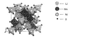
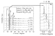
- FIG. 1 It is sectional drawing which shows typically one Embodiment of the anode for alkaline water electrolysis of this invention. It is a figure which shows typically the crystal structure (space group: P4 332 ) of a nickel-containing metal oxide (catalyst). It is a figure which shows typically the change of the valence of Ni with the chemical desorption and insertion of Li in the crystal structure of a nickel-containing metal oxide (catalyst). It is a figure which shows the synchrotron radiation X-ray diffraction pattern of a nickel-containing metal oxide (catalyst).
- FIG. 1 is a cross-sectional view schematically showing an embodiment of the anode for alkaline water electrolysis of the present invention.
- the anode 10 for alkaline water electrolysis of the present embodiment is formed on the surface of the conductive substrate 2, the intermediate layer 4 formed on the surface of the conductive substrate 2, and the surface of the intermediate layer 4.
- the catalyst layer 6 is provided.
- anode for alkaline water electrolysis of the present invention
- the conductive substrate 2 is a conductor for conducting electricity for electrolysis, and is a member having a function as a carrier for supporting the intermediate layer 4 and the catalyst layer 6. At least the surface of the conductive substrate 2 (the surface on which the intermediate layer 4 and the catalyst layer 6 are formed) is made of nickel or a nickel-based alloy. That is, the conductive substrate 2 may be entirely formed of nickel or a nickel-based alloy, or only the surface may be formed of nickel or a nickel-based alloy. Specifically, the conductive substrate 2 may have a nickel or nickel-based alloy coating formed on the surface of a metal material such as iron, stainless steel, aluminum, or titanium by plating or the like.
- the thickness of the conductive substrate is preferably 0.05 to 5 mm.
- the shape of the conductive substrate is preferably a shape having an opening for removing bubbles such as generated oxygen and hydrogen.
- an expanded mesh or a porous expanded mesh can be used as a conductive substrate.
- the aperture ratio of the conductive substrate is preferably 10 to 95%.
- the anode of the present invention preferably includes an intermediate layer arranged between the conductive substrate and the catalyst layer.
- the intermediate layer 4 is a layer formed on the surface of the conductive substrate 2.
- the intermediate layer 4 suppresses corrosion of the conductive substrate 2 and stably fixes the catalyst layer 6 to the conductive substrate 2.
- the intermediate layer 4 also plays a role of rapidly supplying an electric current to the catalyst layer 6.
- the intermediate layer 4 is preferably formed of a lithium-containing nickel oxide represented by the composition formula Li x Ni 2-x O 2 (0.02 ⁇ x ⁇ 0.5). If x in the above composition formula is less than 0.02, the conductivity may be slightly insufficient.
- the intermediate layer 4 formed of the lithium-containing nickel oxide represented by the above composition formula has sufficient conductivity for electrolysis, and exhibits excellent physical strength and chemical stability even when used for a long period of time.
- the thickness of the intermediate layer is preferably 0.01 ⁇ m or more and 100 ⁇ m or less, and more preferably 0.1 ⁇ m or more and 10 ⁇ m or less. If the thickness of the intermediate layer is less than 0.01 ⁇ m, the above-mentioned functions will not be exhibited. On the other hand, even if the thickness of the intermediate layer is more than 100 ⁇ m, the voltage loss due to the resistance in the intermediate layer becomes large and the above-mentioned function is difficult to be exhibited, and there is a case where it is slightly disadvantageous in terms of manufacturing cost and the like.
- the catalyst layer 6 is a layer having a catalytic ability formed on the surface of the intermediate layer 4. By interposing the intermediate layer 4, the catalyst layer 6 is more firmly fixed on the conductive substrate 2.
- the catalyst layer is a layer containing a nickel-containing metal oxide having a spinel structure, and is preferably a layer substantially formed by the nickel-containing metal oxide having a spinel structure.
- the nickel-containing metal oxide contains nickel (Ni) and manganese (Mn), and has an atomic ratio of Li / Ni / Mn / O of (0.0 to 0.8) / (0.4 to Mn). 0.6) / (1.0 to 1.8) /4.0.
- a power source having a large output fluctuation such as renewable energy is used as a power source.
- the electrolytic performance does not easily deteriorate, and excellent catalytic activity can be stably maintained for a long period of time.
- the thickness of the catalyst layer is preferably 0.01 ⁇ m or more and 100 ⁇ m or less, and more preferably 0.1 ⁇ m or more and 10 ⁇ m or less. If the thickness of the catalyst layer is less than 0.01 ⁇ m, the above-mentioned functions will not be exhibited. On the other hand, even if the thickness of the catalyst layer is more than 100 ⁇ m, the voltage loss due to the resistance in the catalyst layer becomes large and the above-mentioned functions are difficult to be exhibited, and there is a case where it is slightly disadvantageous in terms of manufacturing cost and the like.
- the method for manufacturing the anode described below is a method for preferably manufacturing the above-mentioned anode for alkaline water electrolysis.
- the method for producing an anode of the present invention includes a step of preparing a nickel-containing metal oxide and a step of forming a catalyst layer. In the step of preparing the nickel-containing metal oxide, nitronium tetrafluoroborate (NO 2 BF 4 ) is reacted with the lithium composite oxide formed by heat-treating the precursor containing the lithium component, the nickel component, and the manganese component.
- NO 2 BF 4 nitronium tetrafluoroborate
- This is a step of chemically delithiumizing to obtain a nickel-containing metal oxide having a spinel structure having a controlled lithium content.
- the catalyst layer forming step is a step of forming a catalyst layer containing a nickel-containing metal oxide on the surface of the conductive substrate.
- an intermediate layer may be arranged between the conductive substrate and the catalyst layer, if necessary.
- the method for producing the anode in which the intermediate layer is arranged includes a step (coating step) of applying an aqueous solution containing lithium ions and nickel ions to the surface of the conductive substrate before the above-mentioned catalyst layer forming step, and an aqueous solution.
- the conductive substrate coated with the above is heat-treated and is composed of a lithium-containing nickel oxide represented by the composition formula Li x Ni 2-x O 2 (0.02 ⁇ x ⁇ 0.5) on the surface of the conductive substrate. It further comprises a step of forming an intermediate layer (intermediate layer forming step).
- Pretreatment process Before forming the intermediate layer or the catalyst layer, it is preferable to chemically etch the conductive substrate in advance in order to remove contaminated particles such as metals and organic substances on the surface.
- the amount of consumption of the conductive substrate by the chemical etching treatment is preferably about 30 g / m 2 or more and 400 g / m 2 or less.
- an aqueous solution containing lithium ions and nickel ions is applied to the surface of the conductive substrate.
- the intermediate layer is formed by a so-called thermal decomposition method.
- an aqueous precursor solution of the intermediate layer is prepared.
- the precursor containing a lithium component known precursors such as lithium nitrate, lithium carbonate, lithium chloride, lithium hydroxide and lithium carboxylate can be used. Examples of lithium carboxylate include lithium formate and lithium acetate.
- the precursor containing a nickel component known precursors such as nickel nitrate, nickel carbonate, nickel chloride, and nickel carboxylate can be used.
- nickel carboxylate examples include nickel formate and nickel acetate.
- the conductive substrate coated with the aqueous solution is heat-treated.
- an intermediate layer made of a lithium-containing nickel oxide represented by the composition formula Li x Ni 2-x O 2 (0.02 ⁇ x ⁇ 0.5) can be formed on the surface of the conductive substrate. ..
- the heat treatment temperature when forming the intermediate layer by the thermal decomposition method can be appropriately set. Considering the decomposition temperature of the precursor and the production cost, the heat treatment temperature is preferably 450 to 600 ° C, more preferably 450 to 550 ° C.
- the decomposition temperature of lithium nitrate is about 430 ° C
- the decomposition temperature of nickel acetate is about 373 ° C.
- the thickness of the formed intermediate layer can be controlled by appropriately setting the number of times the aqueous solution is applied in the above-mentioned coating step.
- the coating and drying of the aqueous solution may be repeated layer by layer to form the uppermost layer, and then the whole may be heat-treated.
- the coating and heat treatment (pretreatment) of the aqueous solution may be repeated layer by layer to form the uppermost layer, and then the whole may be heat-treated. It may be heat-treated.
- the pretreatment temperature and the overall heat treatment temperature may be the same or different. Further, the pretreatment time is preferably shorter than the total heat treatment time.
- a precursor containing a lithium component, a nickel component, and a manganese component is heat-treated to prepare a lithium composite oxide.
- the lithium component known compounds such as lithium nitrate, lithium carbonate, lithium chloride, lithium hydroxide and lithium carboxylate can be used.
- lithium carboxylate include lithium formate and lithium acetate.
- the nickel component known compounds such as nickel nitrate, nickel carbonate, nickel chloride, and nickel carboxylate can be used.
- nickel carboxylate include nickel formate and nickel acetate.
- manganese component known compounds such as manganese nitrate, manganese carbonate, manganese chloride, and manganese carboxylate can be used.
- manganese carboxylate include manganese formate and manganese acetate.
- the precursor is prepared by adding a lithium component, a nickel component, and a manganese component in a predetermined ratio to an aqueous solution in which excess citric acid is dissolved in ultrapure water to dissolve the precursor, and then heating the mixture at around 300 ° C. Obtainable. Then, the obtained precursor is heat-treated at 400 to 900 ° C., preferably 700 to 900 ° C. for 2 to 50 hours under an oxygen-containing atmosphere to obtain a lithium composite oxide as a target substance (hereinafter, also referred to as “LNMO”). (Note) can be obtained.
- LNMO lithium composite oxide as a target substance
- the oxygen partial pressure in the oxygen-containing atmosphere when the precursor is heat-treated is preferably 0.2 atm or more, and more preferably 0.5 atm or more.
- the flow rate of the gas containing oxygen to be supplied is preferably controlled to 5 mL / min or less as oxygen, and more preferably controlled to 2.5 mL / min or less. If the gas flow rate is too high (too fast), Li tends to be excessively volatilized and the formation of oxides may be excessively promoted, so that the composition of LNMO may easily deviate from the intended composition. be.
- the obtained LNMO can be chemically delithiumized by reacting it with nitronium tetrafluoroborate (NO 2 BF 4 ).
- NO 2 BF 4 nitronium tetrafluoroborate
- Ni nickel
- Mn manganese
- the atomic ratio of Li / Ni / Mn / O is (0.0 to 0.8) / (0.4 to 0.6) / (1). It is possible to obtain a nickel-containing metal oxide having a spinel structure having a controlled lithium content, which is 0.0 to 1.8) / 4.0.
- lithium (Li) is chemically desorbed from LNMO by reacting LNMO and nitronium tetrafluoroborate (NO 2 BF 4 ) in a solvent such as acetonitrile for 2 to 50 hours under room temperature (25 ° C.) conditions. It is possible to obtain a nickel-containing metal oxide which is a target catalyst. By appropriately setting the ratio of LNMO and nitronium tetrafluoroborate (NO 2 BF 4 ), the lithium content of the obtained nickel-containing metal oxide can be controlled.
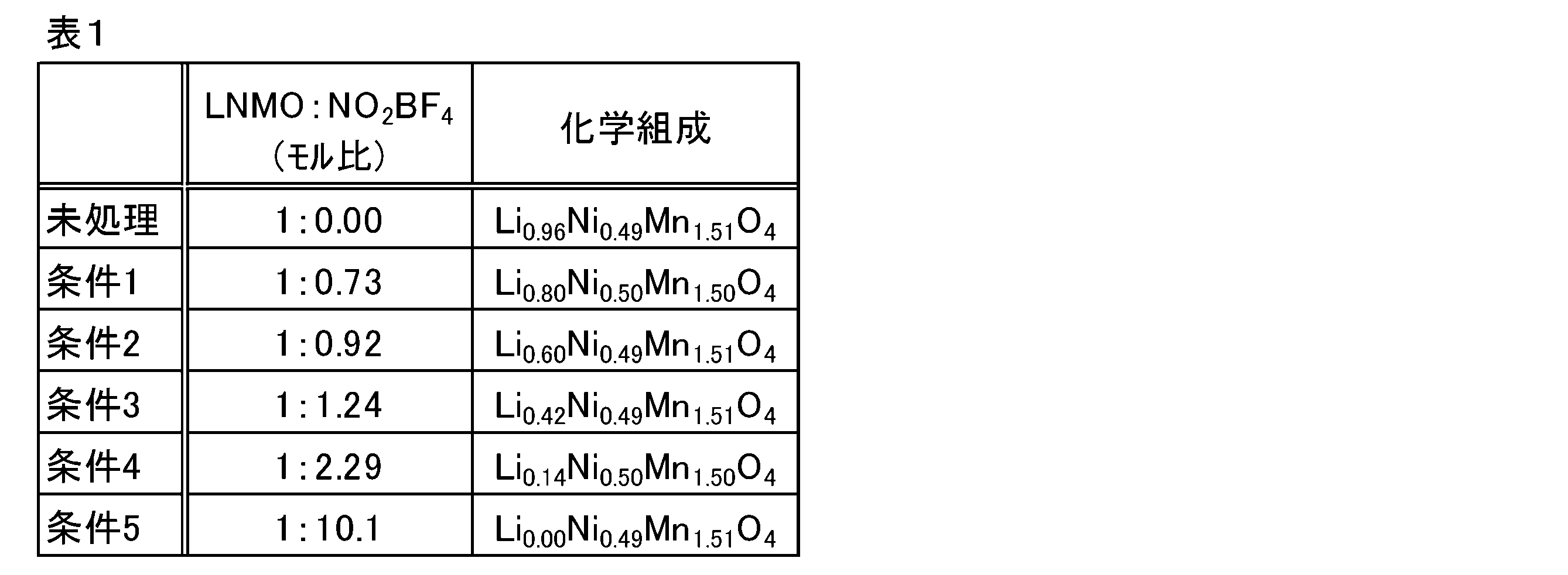
- the lithium content (atomic ratio) of the obtained nickel-containing metal oxide decreases from 0.96 to 0.00.
- the nickel content and manganese content of the obtained nickel-containing metal oxide are substantially the same as the nickel content and manganese content of LNMO, and do not substantially fluctuate.
- nitronium tetrafluoroborate for example, components such as bromine (Br 2 ) gas, nitronium hexafluorophosphate (NO 2 PF 6 ), and nitrosonium hexafluorophosphate (NOPF 6 ) can be added. Even in the reaction, lithium (Li) can be chemically desorbed from LNMO to obtain a nickel-containing metal oxide as a target catalyst. However, from the viewpoint of reactivity and the like, it is particularly preferable to use nitronium tetrafluoroborate (NO 2 BF 4 ).
- the obtained nickel-containing metal oxide can be washed and dried using a vacuum oven or the like before storage.
- Nickel-containing metal oxides can usually be obtained in the form of granules.
- the particle size of the nickel-containing metal oxide is, for example, about 0.1 to 10 ⁇ m. Whether or not the obtained nickel-containing metal oxide has a spinel structure can be confirmed by crystal structure analysis by XRD.
- Catalyst layer formation step In the catalyst layer forming step, a catalyst layer containing a nickel-containing metal oxide as a catalyst is formed on the surface of the conductive substrate. As a result, the desired anode for alkaline water electrolysis can be obtained.
- a conventionally known method may be appropriately adopted, and the present invention is not particularly limited. For example, a catalyst (nickel-containing metal oxide) is added to a solvent containing a specific resin (Nafion (registered trademark)) or the like to prepare a catalyst ink. Then, the prepared catalyst ink is applied to the surface of the conductive substrate or the intermediate layer formed on the conductive substrate, and if necessary, it is heated and dried to form the catalyst layer on the surface of the conductive substrate. Can be formed.
- the anode for alkaline water electrolysis of the present invention can also be suitably manufactured by the method shown below. That is, the method for producing an anode of the present invention includes a lithium composite oxide-containing layer forming step and a catalyst layer forming step.
- the lithium composite oxide-containing layer forming step a precursor containing a lithium component, a nickel component, and a manganese component is heat-treated, and at least the surface thereof is lithium composite oxidation on the surface of a conductive substrate made of nickel or a nickel-based alloy. This is a step of forming a layer containing an object.
- NO 2 BF 4 nitronium tetrafluoroborate
- the precursor aqueous solution containing the above-mentioned lithium component, nickel component, and manganese component is applied to the surface of the conductive substrate. Then, the conductive substrate coated with the precursor aqueous solution on the surface is heat-treated. Thereby, the precursor can be heat-treated, and a lithium composite oxide-containing layer can be formed on the surface of the conductive substrate. That is, the lithium composite oxide-containing layer is formed by a so-called thermal decomposition method.
- a precursor aqueous solution can be prepared by adding a lithium component, a nickel component, and a manganese component in a predetermined ratio to an aqueous solution in which excess citric acid is dissolved in ultrapure water.
- the prepared precursor aqueous solution is applied to the surface of the conductive substrate and heated to around 300 ° C. to form a precursor.
- the formed precursor is heat-treated at 400 to 900 ° C., preferably 700 to 900 ° C. for 2 to 50 hours in an oxygen-containing atmosphere to generate a lithium composite oxide (LNMO) as a target substance.
- LNMO lithium composite oxide
- a lithium composite oxide-containing layer can be formed on the surface of the conductive substrate.
- the oxygen partial pressure in the oxygen-containing atmosphere when the precursor is heat-treated is preferably 0.2 atm or more, and more preferably 0.5 atm or more.
- the flow rate of the gas containing oxygen to be supplied is preferably controlled to 5 mL / min or less as oxygen, and more preferably controlled to 2.5 mL / min or less. If the gas flow rate is too high (too fast), Li tends to be excessively volatilized and the formation of oxides may be excessively promoted, so that the composition of LNMO may easily deviate from the intended composition. be.
- Catalyst layer formation step In the catalyst layer forming step, nitronium tetrafluoroborate (NO 2 BF 4 ) is reacted with LNMO contained in the formed lithium composite oxide-containing layer to chemically delithiumize it. As a result, nickel (Ni) and manganese (Mn) are contained, and the atomic ratio of Li / Ni / Mn / O is (0.0 to 0.8) / (0.4 to 0.6) / (1).
- a conductive substrate having a lithium composite oxide-containing layer formed on its surface is immersed in a solvent such as acetonitrile, and nitronium tetrafluoroborate (NO 2 BF 4 ) is added at room temperature (25 ° C.) for 2 to 2 to.
- nitronium tetrafluoroborate NO 2 BF 4
- Li lithium
- Ni nitronium tetrafluoroborate
- the lithium content of the obtained nickel-containing metal oxide can be controlled.
- the lithium content (atomic ratio) of the obtained nickel-containing metal oxide decreases from 0.96 to 0.00.
- the nickel content and manganese content of the nickel-containing metal oxide formed are substantially the same as the nickel content and manganese content of LNMO, and do not substantially fluctuate. Whether or not the formed nickel-containing metal oxide has a spinel structure can be confirmed by crystal structure analysis by XRD.
- the anode for alkaline water electrolysis of the present invention can be used as an anode for oxygen generation when electrolyzing alkaline water. That is, if the anode of the present invention is used, an electrolytic cell such as an alkaline water electrolytic cell can be configured.
- the type and configuration of the cathode and the diaphragm used together with the above-mentioned anode are not particularly limited, and the cathode and the diaphragm used in the conventional alkaline water electrolysis can be used.
- the cathode As the cathode, it is preferable to select and use a substrate made of a material that can withstand alkaline water electrolysis and a catalyst having a small cathode overvoltage.
- a nickel substrate or a nickel substrate coated with an active cathode can be used.
- Examples of the shape of the cathode substrate include a plate-like shape, an expanded mesh, a porous expanded mesh, and the like.
- the cathode material examples include porous nickel having a large surface area and Ni—Mo-based materials.
- nickel-based materials such as Ni-Al, Ni-Zn, and Ni-Co-Zn
- sulfide-based materials such as Ni-S
- hydrogen storage alloy-based materials such as Ti 2 Ni.
- the catalyst preferably has properties such as low hydrogen overvoltage, high short-circuit stability, and high poisoning resistance.
- metals such as platinum, palladium, ruthenium and iridium, and oxides thereof are preferable.
- diaphragm As the diaphragm for electrolysis, asbestos, a non-woven fabric, an ion exchange membrane, a polymer porous membrane, a composite membrane of an inorganic substance and an organic polymer, and the like can be used. Specifically, an ion-permeable diaphragm in which an organic fiber cloth is embedded in a mixture of a hydrophilic inorganic material such as a calcium phosphate compound or calcium fluoride and an organic binding material such as polysulfone, polypropylene, and polyvinylidene fluoride is formed. Can be used.
- a hydrophilic inorganic material such as a calcium phosphate compound or calcium fluoride
- organic binding material such as polysulfone, polypropylene, and polyvinylidene fluoride
- organic binders such as fluorocarbon polymers, polysulfone, polypropylene, polyvinyl chloride and polyvinyl butyral.
- an ion-permeable diaphragm having a stretched organic fiber cloth embedded therein can be used.
- a high-concentration alkaline aqueous solution can be electrolyzed.
- an aqueous solution of an alkali metal hydroxide such as potassium hydroxide (KOH) and sodium hydroxide (NaOH) is preferable.
- the concentration of the alkaline aqueous solution is preferably 1.5% by mass or more and 40% by mass or less. Further, it is preferable that the concentration of the alkaline aqueous solution is 15% by mass or more and 40% by mass or less because the electric conductivity is large and the power consumption can be suppressed. Further, in consideration of cost, corrosiveness, viscosity, operability, etc., the concentration of the alkaline aqueous solution is preferably 20% by mass or more and 30% by mass or less.
- the composition was analyzed by inductively coupled plasma (ICP) emission spectroscopy using a solution obtained by dissolving a part of the obtained standard substance in an acid as a sample.
- the product name "ICPS-8100CL” manufactured by Shimadzu Corporation
- ICPS-8100CL manufactured by Shimadzu Corporation
- the obtained target substance (LNMO) and nitronium tetrafluoroborate (NO 2 BF 4 ) were added to acetonitrile so as to have a quantitative ratio (molar ratio) of conditions 1 to 5 shown in Table 1, respectively, and the mixture was added to acetonitrile at room temperature for 48 hours. It was reacted.
- the suspension after the reaction was filtered, washed with acetonitrile three times, and dried overnight using a vacuum oven to obtain a catalyst (nickel-containing metal oxide) having the chemical composition shown in Table 1.
- the chemical composition of the obtained catalyst (nickel-containing metal oxide) was identified by inductively coupled plasma (ICP) emission spectroscopy.
- FIG. 2 is a diagram schematically showing a crystal structure (space group: P4 3 32) of a nickel-containing metal oxide (catalyst).
- FIG. 3 is a diagram schematically showing the change in the valence of Ni due to the chemical desorption and insertion of Li in the crystal structure of the nickel-containing metal oxide (catalyst).
- NO 2 BF 4 nitronium tetrafluoroborate
- the ratio of manganese (Mn) having a valence of 4 to all manganese (Mn) in the nickel-containing metal oxide can be measured by, for example, X-ray absorption spectroscopy.
- FIG. 4 is a diagram showing a synchrotron radiation X-ray diffraction pattern of a nickel-containing metal oxide (catalyst). As shown in FIG. 4, all peaks were indexed into the tertiary phase and the space group P4 332, and no impurities were observed. According to the TEM image, the structure was maintained even after delithiumization. The average particle size of the nickel-containing metal oxide (catalyst) measured from the SEM image was about 1.5 ⁇ m.
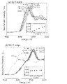
- FIG. 5 is a diagram showing XANES spectra of Ni K-edge ((a)) and Mn K-edge ((b)) of nickel-containing metal oxide (catalyst).
- Mn hardly changed, while the electronic state of Ni changed significantly.
- the K-edge XANES spectrum of Ni ((a)) shows a monotonous edge shift to higher energies with an average oxidation state of Ni from Ni 2+ to Ni 0.5 in LiNi 0.5 Mn 1.5 O 4 . It was shown that the change was made to Ni 4+ in Mn 1.5 O 4 . Further, it was confirmed that the K-edge XANES spectrum ((b)) of Mn changed slightly, but the state of Mn 4+ was maintained. From the above, it can be seen that the electronic structure of Ni can be controlled without changing the electronic structure of Mn by chemical oxidation using NO 2 BF 4 .
- LSV linear sweep voltammetry
- the Tafel gradient (slope) changed from about 98 mV ⁇ dec -1 to about 66 mV ⁇ dec -1 as x (Li) decreased. It is speculated that the change in Tafel gradient (slope) enhances the adsorption of OH intermediates caused by the covalent bond state of Ni species. That is, it is presumed that the factor for improving the oxygen evolution ability of the catalyst is not the increase in the reaction rate in the rate-determining step but the change in the reaction path.
- Example 1 As an anode substrate, a nickel expanded mesh (10 cm x 10 cm, LW x 3.7 SW x 0.9 ST x 0.8 T) prepared by immersing it in 17.5% hydrochloric acid heated to near the boiling point for 6 minutes and chemically etching it. bottom. This expanded mesh was blasted (0.3 MPa) with 60 mesh alumina particles, then immersed in 20% hydrochloric acid heated to near the boiling point and immersed for 6 minutes for chemical etching. An aqueous solution containing a component serving as a precursor of a lithium-containing nickel oxide was applied to the surface of the anode substrate after the chemical etching treatment with a brush, and then dried at 80 ° C.
- a small zero-gap electrolytic cell using a neutral diaphragm using the obtained anode, diaphragm (trade name "Zirphon", manufactured by AGFA), and an active cathode having a catalyst layer composed of Ru and Pr oxide. was produced.
- the electrode area was 19 cm 2 .
- An electrolytic solution (25% KOH aqueous solution) was supplied to the anode chamber and the cathode chamber constituting the electrolytic cell, and electrolysis was performed at a current density of 6 kA / m 2 for 6 hours each. The overvoltage at this time was 250 mV.
- the anode and cathode were short-circuited (0 kA / m 2 ) and stopped for 15 hours.
- a shutdown test was conducted in which the operation from electrolysis to stop was one cycle. As a result, it was confirmed that the voltage was kept stable in 15 shutdown tests.
- Example 2 LiNO 3 , Ni (NO 3 ) 2.6H 2 O, and Mn (NO 3 ) 2.6H 2 O were dissolved in ultrapure water to prepare a coating liquid having a total metal concentration of 75 g / L.
- the coating liquid was applied to a substrate having an intermediate formed in the same manner as in Example 1, dried at 60 ° C., then fired in an electric furnace at 500 ° C. for 15 minutes, and then cooled.
- the operation from application of the coating liquid to cooling was repeated 10 times to form a catalyst layer of about 10 g / m 2 as a metal oxide.
- the substrate on which the catalyst layer was formed was heat-treated (post-baked) in air at 500 ° C. for 1 hour, 3 hours, and 10 hours.
- a substrate having a catalyst layer is placed in a PTFE container filled with a solution of an excess amount of nitronium tetrafluoroborate (NO 2 BF 4 ) in acetonitrile, and a delithium reaction is carried out at room temperature for 70 hours with stirring. Was carried out.
- an electrode catalyst layer composition: Li 0.00 Ni 0.50 Mn 1.50 O 4 ) from which the Li component in the LNMO catalyst was almost removed was obtained.
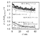
- FIG. 7 shows the results (after delithium removal) when electrolysis at 1 A / cm 2 was continued for 60 minutes.
- the electrode subjected to post-baking for 1 hour was initially 1.75 V, but gradually decreased to 1.65 V.
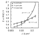
- FIG. 7 shows the results (before delithium removal) of current-potential measurement in oxygen evolution for the obtained electrodes. As shown in FIG. 7, all electrodes are 1.8 V vs. at 0.5 A / cm 2 . It showed a noble potential of about RHE. Further, FIG. 8 shows the potential change (before delithium removal) when electrolysis at 1 A / cm 2 was continued for 60 minutes. As shown in FIG. 8, the electrode subjected to post-baking for 1 hour had an initial value of 2.05 V, increased to 2.1 V once, and then gradually decreased to 2.05 V.
- the electrode of Example 2 has improved performance by about 0.4 V as compared with the electrode of Comparative Example 1. Further, since the Tafel gradient of the electrode of Example 2 is significantly smaller than the Tapel gradient of the electrode of Comparative Example 1, it can be seen that the reaction catalytic activity was improved by delithiumization.
- the anode for alkaline water electrolysis of the present invention is suitable as, for example, an anode for alkaline water electrolysis constituting an electrolytic facility or the like whose power source is electric power having a large output fluctuation such as renewable energy.
Abstract
Description
[1]少なくともその表面がニッケル又はニッケル基合金からなる導電性基体と、前記導電性基体の表面上に配置された、スピネル構造を有するニッケル含有金属酸化物を含む触媒層と、を備え、前記ニッケル含有金属酸化物が、ニッケル(Ni)及びマンガン(Mn)を含むとともに、Li/Ni/Mn/Oの原子比が、(0.0~0.8)/(0.4~0.6)/(1.0~1.8)/4.0であるアルカリ水電解用アノード。
[2]前記ニッケル含有金属酸化物中のすべてのマンガン(Mn)に占める、価数が4のマンガン(Mn)の割合が、99モル%以上である前記[1]に記載のアルカリ水電解用アノード。
[3]前記導電性基体と前記触媒層の間に配置される、組成式LixNi2-xO2(0.02≦x≦0.5)で表されるリチウム含有ニッケル酸化物からなる中間層をさらに備える前記[1]又は[2]に記載のアルカリ水電解用アノード。
[4]リチウム成分、ニッケル成分、及びマンガン成分を含有する前駆体を熱処理して、少なくともその表面がニッケル又はニッケル基合金からなる導電性基体の表面上にリチウム複合酸化物を含む層を形成する工程と、前記リチウム複合酸化物にテトラフルオロほう酸ニトロニウム(NO2BF4)を反応させて化学的に脱リチウム化し、リチウム含有量が制御されたスピネル構造を有するニッケル含有金属酸化物を含む触媒層を前記導電性基体の表面上に形成する工程と、を有し、前記ニッケル含有金属酸化物が、ニッケル(Ni)及びマンガン(Mn)を含むとともに、Li/Ni/Mn/Oの原子比が、(0.0~0.8)/(0.4~0.6)/(1.0~1.8)/4.0であるアルカリ水電解用アノードの製造方法。
[5]前記前駆体を、酸素含有雰囲気下、400~900℃で熱処理する前記[4]に記載のアルカリ水電解用アノードの製造方法。
[6]前記前駆体を、0.2気圧以上の酸素分圧の酸素含有雰囲気下で熱処理する前記[4]又は[5]に記載のアルカリ水電解用アノードの製造方法。
図1は、本発明のアルカリ水電解用アノードの一実施形態を模式的に示す断面図である。図1に示すように、本実施形態のアルカリ水電解用アノード10は、導電性基体2と、導電性基体2の表面上に形成された中間層4と、中間層4の表面上に形成された触媒層6とを備える。以下、本発明のアルカリ水電解用アノード(以下、単に「アノード」とも記す)の詳細について説明する。
導電性基体2は、電気分解のための電気を通すための導電体であり、中間層4及び触媒層6を担持する担体としての機能を有する部材である。導電性基体2の少なくとも表面(中間層4や触媒層6が形成される面)は、ニッケル又はニッケル基合金で形成されている。すなわち、導電性基体2は、全体がニッケル又はニッケル基合金で形成されていてもよく、表面のみがニッケル又はニッケル基合金で形成されていてもよい。具体的に、導電性基体2は、鉄、ステンレス、アルミニウム、チタン等の金属材料の表面に、めっき等によりニッケル又はニッケル基合金のコーティングが形成されたものであってもよい。
本発明のアノードは、導電性基体と前記触媒層の間に配置される中間層を備えることが好ましい。図1に示すように、中間層4は、導電性基体2の表面上に形成される層である。中間層4は、導電性基体2の腐食等を抑制するとともに、触媒層6を導電性基体2に安定的に固着させる。また、中間層4は、触媒層6に電流を速やかに供給する役割も果たす。中間層4は、組成式LixNi2-xO2(0.02≦x≦0.5)で表されるリチウム含有ニッケル酸化物で形成されていることが好ましい。上記組成式中のxが0.02未満であると、導電性がやや不十分になることがある。一方、xが0.5を超えると物理的強度及び化学的安定性がやや低下することがある。上記組成式で表されるリチウム含有ニッケル酸化物で形成された中間層4は、電解に十分な導電性を有するとともに、長期間使用した場合でも優れた物理的強度及び化学的安定性を示す。
触媒層6は、中間層4の表面上に形成される触媒能を有する層である。中間層4を介在させることで、触媒層6は導電性基体2上により強固に固定されている。
次に、本発明のアルカリ水電解用アノードの製造方法について説明する。以下で説明するアノードの製造方法は、前述のアルカリ水電解用アノードを好適に製造する方法である。本発明のアノードの製造方法は、ニッケル含有金属酸化物の調製工程と、触媒層形成工程とを有する。ニッケル含有金属酸化物の調製工程は、リチウム成分、ニッケル成分、及びマンガン成分を含有する前駆体を熱処理して形成したリチウム複合酸化物に、テトラフルオロほう酸ニトロニウム(NO2BF4)を反応させて化学的に脱リチウム化し、リチウム含有量が制御されたスピネル構造を有するニッケル含有金属酸化物を得る工程である。また、触媒層形成工程は、導電性基体の表面上にニッケル含有金属酸化物を含む触媒層を形成する工程である。
中間層や触媒層を形成する前に、表面の金属や有機物などの汚染粒子を除去するために、導電性基体を予め化学エッチング処理することが好ましい。化学エッチング処理による導電性基体の消耗量は、30g/m2以上400g/m2以下程度とすることが好ましい。また、中間層や触媒層との密着力を高めるために、導電性基体の表面を予め粗面化処理することが好ましい。粗面化処理の手段としては、粉末を吹き付けるブラスト処理や、基体可溶性の酸を用いたエッチング処理や、プラズマ溶射などを挙げることができる。
塗布工程では、リチウムイオン及びニッケルイオンを含有する水溶液を導電性基体の表面に塗布する。中間層は、いわゆる熱分解法によって形成される。熱分解法により中間層を形成するに際しては、まず、中間層の前駆体水溶液を調製する。リチウム成分を含む前駆体としては、硝酸リチウム、炭酸リチウム、塩化リチウム、水酸化リチウム、カルボン酸リチウムなど公知の前駆体を使用することができる。カルボン酸リチウムとしては、ギ酸リチウムや酢酸リチウムを挙げることができる。ニッケル成分を含む前駆体としては、硝酸ニッケル、炭酸ニッケル、塩化ニッケル、カルボン酸ニッケルなど公知の前駆体を使用することができる。カルボン酸ニッケルとしては、ギ酸ニッケルや酢酸ニッケルを挙げることができる。特に、前駆体としてカルボン酸リチウム及びカルボン酸ニッケルの少なくとも一方を用いることにより、後述するように低温で焼成した場合であっても緻密な中間層を形成することができるので特に好ましい。
中間層形成工程では、水溶液を塗布した導電性基体を熱処理する。これにより、組成式LixNi2-xO2(0.02≦x≦0.5)で表されるリチウム含有ニッケル酸化物からなる中間層を導電性基体の表面上に形成することができる。熱分解法で中間層を形成する際の熱処理温度は、適宜設定することができる。前駆体の分解温度と生産コストとを考慮すると、熱処理温度は450~600℃とすることが好ましく、450~550℃とすることがさらに好ましい。例えば、硝酸リチウムの分解温度は430℃程度であり、酢酸ニッケルの分解温度は373℃程度である。熱処理温度を450℃以上とすることにより、各成分をより確実に分解することができる。熱処理温度を600℃超とすると、導電性基体の酸化が進行しやすく、電極抵抗が増大して電圧損失の増大を招く場合がある。熱処理時間は、反応速度、生産性、中間層表面の酸化抵抗等を考慮して適宜設定すればよい。
ニッケル含有金属酸化物の調製工程では、まず、リチウム成分、ニッケル成分、及びマンガン成分を含有する前駆体を熱処理して、リチウム複合酸化物を調製する。リチウム成分としては、硝酸リチウム、炭酸リチウム、塩化リチウム、水酸化リチウム、カルボン酸リチウムなど公知の化合物を使用することができる。カルボン酸リチウムとしては、ギ酸リチウムや酢酸リチウムを挙げることができる。ニッケル成分としては、硝酸ニッケル、炭酸ニッケル、塩化ニッケル、カルボン酸ニッケルなど公知の化合物を使用することができる。カルボン酸ニッケルとしては、ギ酸ニッケルや酢酸ニッケルを挙げることができる。特に、カルボン酸リチウム及びカルボン酸ニッケルの少なくとも一方を用いることにより、より緻密な触媒層を形成することができるので好ましい。マンガン成分としては、硝酸マンガン、炭酸マンガン、塩化マンガン、カルボン酸マンガンなど公知の化合物を使用することができる。カルボン酸マンガンとしては、ギ酸マンガンや酢酸マンガンを挙げることができる。
触媒層形成工程では、導電性基体の表面上に、触媒であるニッケル含有金属酸化物を含む触媒層を形成する。これにより、目的とするアルカリ水電解用アノードを得ることができる。導電性基体の表面上に触媒層を形成するには、従来公知の方法を適宜採用すればよく、特に限定されない。例えば、特定の樹脂(ナフィオン(登録商標))等を含有する溶剤に触媒(ニッケル含有金属酸化物)を添加して触媒インクを調製する。そして、調製した触媒インクを導電性基体又は導電性基体上に形成した中間層の表面に塗布するとともに、必要に応じて加熱等して乾燥させることで、導電性基体の表面上に触媒層を形成することができる。
また、本発明のアルカリ水電解用アノードは、以下に示す方法によって好適に製造することもできる。すなわち、本発明のアノードの製造方法は、リチウム複合酸化物含有層形成工程と、触媒層形成工程とを有する。リチウム複合酸化物含有層形成工程は、リチウム成分、ニッケル成分、及びマンガン成分を含有する前駆体を熱処理して、少なくともその表面がニッケル又はニッケル基合金からなる導電性基体の表面上にリチウム複合酸化物を含む層を形成する工程である。また、触媒層形成工程は、リチウム複合酸化物にテトラフルオロほう酸ニトロニウム(NO2BF4)を反応させて化学的に脱リチウム化し、リチウム含有量が制御されたスピネル構造を有するニッケル含有金属酸化物を含む触媒層を導電性基体の表面上に形成する工程である。
触媒層形成工程では、形成されたリチウム複合酸化物含有層に含まれるLNMOにテトラフルオロほう酸ニトロニウム(NO2BF4)を反応させて化学的に脱リチウム化する。これにより、ニッケル(Ni)及びマンガン(Mn)を含むとともに、Li/Ni/Mn/Oの原子比が、(0.0~0.8)/(0.4~0.6)/(1.0~1.8)/4.0である、リチウム含有量が制御されたスピネル構造を有するニッケル含有金属酸化物が生成し、このニッケル含有金属酸化物を含む触媒層を導電性基体の表面上に形成することができる。
本発明のアルカリ水電解用アノードは、アルカリ水を電気分解する際の酸素発生用アノードとして用いることができる。すなわち、本発明のアノードを用いれば、アルカリ水電解セル等の電解セルを構成することができる。上記のアノードとともに用いる陰極(カソード)や隔膜の種類や構成等については特に限定されず、従来のアルカリ水電解に用いられるカソードや隔膜を用いることができる。
カソードとしては、アルカリ水電解に耐えうる材料製の基体と、陰極過電圧が小さい触媒とを選択して用いることが好ましい。陰極基体としては、ニッケル基体、又はニッケル基体に活性陰極を被覆形成したものを用いることができる。陰極基体の形状としては、板状の他、エクスパンドメッシュや、多孔質エクスパンドメッシュなどを挙げることができる。
電解用の隔膜としては、アスベスト、不織布、イオン交換膜、高分子多孔膜、及び無機物質と有機高分子の複合膜などを用いることができる。具体的には、リン酸カルシウム化合物やフッ化カルシウム等の親水性無機材料と、ポリスルホン、ポリプロピレン、及びフッ化ポリビニリデン等の有機結合材料との混合物に、有機繊維布を内在させたイオン透過性隔膜を用いることができる。また、アンチモンやジルコニウムの酸化物及び水酸化物等の粒状の無機性親水性物質と、フルオロカーボン重合体、ポリスルホン、ポリプロピレン、ポリ塩化ビニル、及びポリビニルブチラール等の有機性結合剤とのフィルム形成性混合物に、伸張された有機性繊維布を内在させたイオン透過性隔膜を用いることができる。
(製造例1)
化学量論量のLiNO3、Ni(NO3)2・6H2O、及びMn(NO3)2・6H2Oを超純水に溶解させた。撹拌しながら4倍モル過剰の無水クエン酸を添加した後、300℃に加熱して、粉末状の前駆体を得た。得られた前駆体を800℃で12時間焼成した後、さらに700℃で48時間焼成して、粉末状の標的物質(LNMO)を得た。得られた標準物質の一部を酸に溶解して得た溶液を試料とし、誘導結合プラズマ(ICP)発光分光分析法により組成を分析した。誘導結合プラズマ発光分析装置としては、製品名「ICPS-8100CL」(島津製作所社製)を使用した。その結果、得られた標的物質(LNMO)の化学組成は「Li0.96Ni0.49Mn1.51O4」で表されることを確認した。
[三電極セル]:
・作用極:触媒被覆GC
・参照極:可逆水素電極(RHE)
・対極:Ptメッシュ
・電解液:0.1mol/L KOH水溶液
(実施例1)
陽極基体として、沸点付近まで加熱した17.5%塩酸に6分間浸漬して化学エッチング処理したニッケル製のエクスパンドメッシュ(10cm×10cm、LW×3.7SW×0.9ST×0.8T)を用意した。このエクスパンドメッシュを、60メッシュのアルミナ粒子でブラスト処理(0.3MPa)した後、沸点付近まで加熱した20%塩酸に浸漬し6分間浸漬して化学エッチング処理した。化学エッチング処理後の陽極基体の表面に、リチウム含有ニッケル酸化物の前駆体となる成分を含有する水溶液を刷毛で塗布した後、80℃で15分間乾燥させた。次いで、酸素雰囲気下、600℃で15分間熱処理した。水溶液の塗布から熱処理までの処理を20回繰り返して、陽極基体の表面上に中間層(組成:Li0.5Ni1.5O2)が形成された中間体を得た。
LiNO3、Ni(NO3)2・6H2O、及びMn(NO3)2・6H2Oを超純水に溶解させ、全金属濃度75g/Lの塗布液を調製した。塗布液中の各金属のモル比率は、Li:Ni:Mn=0.33:0.17:0.5であった。実施例1と同様の中間体を形成した基材に塗布液を塗布した後、60℃で乾燥し、次いで、500℃の電気炉で15分間焼成してから冷却した。塗布液の塗布から冷却までの操作を10回繰り返して、金属酸化物として約10g/m2の触媒層を形成した。次いで、触媒層を形成した基材を、空気中、500℃で1時間、3時間、及び10時間熱処理(ポストベーク)した。過剰量のテトラフルオロホウ酸ニトロニウム(NO2BF4)をアセトニトリルに溶解させた溶液を満たしたPTFE製の容器に触媒層を形成した基材を入れ、撹拌しながら室温で70時間、脱リチウム反応を実施した。アセトニトリルで3回洗浄してから乾燥させて、LNMO触媒中のLi成分をほぼ除去した電極(触媒層の組成:Li0.00Ni0.50Mn1.50O4)を得た。得られた電極を作用極、及びPtメッシュを対極とし、60℃の7mol/L KOH水溶液中で、酸素発生における電流-電位測定を行った。結果(脱リチウム後)を図7に示す。図7に示すように、いずれの電極も、0.5A/cm2で1.6V vs.RHE程度の卑な電位を示した。また、ポストベークの時間が短い電極ほど、卑な電位を示した。さらに、1A/cm2で60分間の電解を継続したときの電位変化(脱リチウム後)を図8に示す。図8に示すように、ポストベークを1時間行った電極は初期1.75Vであったが、1.65Vまで次第に低下した。
脱リチウム反応を実施しなかったこと以外は、前述の実施例2と同様にして、触媒(LNMO触媒)層を有する電極を得た。得られた電極につき、酸素発生における電流-電位測定を行った結果(脱リチウム前)を図7に示す。図7に示すように、いずれの電極も、0.5A/cm2で1.8V vs.RHE程度の貴な電位を示した。また、1A/cm2で60分間の電解を継続したときの電位変化(脱リチウム前)を図8に示す。図8に示すように、ポストベークを1時間行った電極は初期2.05Vであり、一度2.1Vまで増加した後、2.05Vまで次第に低下した。実施例2の電極は、比較例1の電極に比して0.4V程度性能が向上したことがわかる。また、実施例2の電極のTafel勾配は、比較例1の電極のTafel勾配よりも大幅に小さくなっていることから、脱リチウムによって反応触媒活性が向上したことがわかる。
4:中間層
6:触媒層
10:アルカリ水電解用アノード
Claims (6)
- 少なくともその表面がニッケル又はニッケル基合金からなる導電性基体と、
前記導電性基体の表面上に配置された、スピネル構造を有するニッケル含有金属酸化物を含む触媒層と、を備え、
前記ニッケル含有金属酸化物が、ニッケル(Ni)及びマンガン(Mn)を含むとともに、Li/Ni/Mn/Oの原子比が、(0.0~0.8)/(0.4~0.6)/(1.0~1.8)/4.0であるアルカリ水電解用アノード。 - 前記ニッケル含有金属酸化物中のすべてのマンガン(Mn)に占める、価数が4のマンガン(Mn)の割合が、99モル%以上である請求項1に記載のアルカリ水電解用アノード。
- 前記導電性基体と前記触媒層の間に配置される、組成式LixNi2-xO2(0.02≦x≦0.5)で表されるリチウム含有ニッケル酸化物からなる中間層をさらに備える請求項1又は2に記載のアルカリ水電解用アノード。
- リチウム成分、ニッケル成分、及びマンガン成分を含有する前駆体を熱処理して、少なくともその表面がニッケル又はニッケル基合金からなる導電性基体の表面上にリチウム複合酸化物を含む層を形成する工程と、
前記リチウム複合酸化物にテトラフルオロほう酸ニトロニウム(NO2BF4)を反応させて化学的に脱リチウム化し、リチウム含有量が制御されたスピネル構造を有するニッケル含有金属酸化物を含む触媒層を前記導電性基体の表面上に形成する工程と、を有し、
前記ニッケル含有金属酸化物が、ニッケル(Ni)及びマンガン(Mn)を含むとともに、Li/Ni/Mn/Oの原子比が、(0.0~0.8)/(0.4~0.6)/(1.0~1.8)/4.0であるアルカリ水電解用アノードの製造方法。 - 前記前駆体を、酸素含有雰囲気下、400~900℃で熱処理する請求項4に記載のアルカリ水電解用アノードの製造方法。
- 前記前駆体を、0.2気圧以上の酸素分圧の酸素含有雰囲気下で熱処理する請求項4又は5に記載のアルカリ水電解用アノードの製造方法。
Priority Applications (6)
| Application Number | Priority Date | Filing Date | Title |
|---|---|---|---|
| CA3194839A CA3194839C (en) | 2020-10-15 | 2021-10-14 | Anode for alkaline water electrolysis and method for producing same |
| KR1020237014450A KR102586625B1 (ko) | 2020-10-15 | 2021-10-14 | 알칼리 수전해용 애노드 및 그의 제조 방법 |
| JP2022557457A JP7261418B2 (ja) | 2020-10-15 | 2021-10-14 | アルカリ水電解用アノード及びその製造方法 |
| CN202180070376.8A CN116322983B (zh) | 2020-10-15 | 2021-10-14 | 碱水电解用阳极和其制造方法 |
| US18/248,848 US11965256B2 (en) | 2020-10-15 | 2021-10-14 | Anode for alkaline water electrolysis and method for producing same |
| EP21880200.7A EP4230772A1 (en) | 2020-10-15 | 2021-10-14 | Anode for alkaline water electrolysis and method for producing same |
Applications Claiming Priority (2)
| Application Number | Priority Date | Filing Date | Title |
|---|---|---|---|
| JP2020174095 | 2020-10-15 | ||
| JP2020-174095 | 2020-10-15 |
Publications (1)
| Publication Number | Publication Date |
|---|---|
| WO2022080465A1 true WO2022080465A1 (ja) | 2022-04-21 |
Family
ID=81208158
Family Applications (1)
| Application Number | Title | Priority Date | Filing Date |
|---|---|---|---|
| PCT/JP2021/038116 WO2022080465A1 (ja) | 2020-10-15 | 2021-10-14 | アルカリ水電解用アノード及びその製造方法 |
Country Status (6)
| Country | Link |
|---|---|
| EP (1) | EP4230772A1 (ja) |
| JP (1) | JP7261418B2 (ja) |
| KR (1) | KR102586625B1 (ja) |
| CN (1) | CN116322983B (ja) |
| CA (1) | CA3194839C (ja) |
| WO (1) | WO2022080465A1 (ja) |
Citations (7)
| Publication number | Priority date | Publication date | Assignee | Title |
|---|---|---|---|---|
| JP2015086420A (ja) | 2013-10-29 | 2015-05-07 | 国立大学法人横浜国立大学 | アルカリ水電解用陽極 |
| JP2017190476A (ja) | 2016-04-12 | 2017-10-19 | デノラ・ペルメレック株式会社 | アルカリ水電解用陽極及びアルカリ水電解用陽極の製造方法 |
| JP2017538250A (ja) * | 2014-11-03 | 2017-12-21 | バイエリシエ・モトーレンウエルケ・アクチエンゲゼルシヤフト | リチウムベースの蓄エネルギー器用の電解質 |
| JP2018178221A (ja) * | 2017-04-18 | 2018-11-15 | 株式会社豊田自動織機 | 脂肪酸塩の製造方法 |
| WO2019172160A1 (ja) * | 2018-03-07 | 2019-09-12 | デノラ・ペルメレック株式会社 | 電解用電極及びその製造方法 |
| WO2020032256A1 (ja) * | 2018-08-09 | 2020-02-13 | 国立研究開発法人理化学研究所 | 水電気分解法及び装置、並びに水電気分解の駆動電位の決定方法 |
| JP6975297B1 (ja) * | 2020-08-28 | 2021-12-01 | デノラ・ペルメレック株式会社 | アルカリ水電解用アノード |
Family Cites Families (11)
| Publication number | Priority date | Publication date | Assignee | Title |
|---|---|---|---|---|
| JP2002042814A (ja) * | 2000-07-28 | 2002-02-08 | Hitachi Maxell Ltd | 非水二次電池用正極活物質およびそれを用いた非水二次電池 |
| JP2005060162A (ja) * | 2003-08-11 | 2005-03-10 | Sumitomo Metal Mining Co Ltd | リチウムマンガンニッケル複合酸化物の製造方法、およびそれを用いた非水系電解質二次電池用正極活物質 |
| MA34393B1 (fr) * | 2010-06-24 | 2013-07-03 | Univ Rutgers | Catalyseurs de type spinelles pour oxydation de l'eau et d'hydrocarbures |
| JP5803539B2 (ja) * | 2011-10-11 | 2015-11-04 | 株式会社豊田自動織機 | リチウム含有複合酸化物粉末の製造方法 |
| WO2016143681A1 (ja) * | 2015-03-06 | 2016-09-15 | 公立大学法人兵庫県立大学 | リチウムニッケルマンガン複合酸化物及びその製造方法並びにそれを用いた正極及び蓄電デバイス |
| CN105118983B (zh) * | 2015-09-16 | 2017-05-17 | 湖北宇电能源科技股份有限公司 | 一种镍锰酸锂正极材料的制备方法 |
| CN105118988A (zh) * | 2015-10-08 | 2015-12-02 | 清华大学深圳研究生院 | 锂离子电池用高电压尖晶石结构正极材料及制备方法 |
| CA3036352C (en) * | 2016-09-09 | 2020-09-15 | De Nora Permelec Ltd | Method for producing anode for alkaline water electrolysis, and anode for alkaline water electrolysis |
| JP6764994B2 (ja) * | 2017-02-21 | 2020-10-07 | 旭化成株式会社 | 陽極、水電解用陽極、電解セル、及び水素の製造方法 |
| WO2018169004A1 (ja) * | 2017-03-16 | 2018-09-20 | 国立研究開発法人産業技術総合研究所 | ニッケルマンガン系複合酸化物及びその製造方法 |
| CN111592053A (zh) * | 2020-06-30 | 2020-08-28 | 国联汽车动力电池研究院有限责任公司 | 一种镍基层状锂离子电池正极材料及其制备方法与应用 |
-
2021
- 2021-10-14 JP JP2022557457A patent/JP7261418B2/ja active Active
- 2021-10-14 CN CN202180070376.8A patent/CN116322983B/zh active Active
- 2021-10-14 KR KR1020237014450A patent/KR102586625B1/ko active IP Right Grant
- 2021-10-14 WO PCT/JP2021/038116 patent/WO2022080465A1/ja unknown
- 2021-10-14 CA CA3194839A patent/CA3194839C/en active Active
- 2021-10-14 EP EP21880200.7A patent/EP4230772A1/en active Pending
Patent Citations (7)
| Publication number | Priority date | Publication date | Assignee | Title |
|---|---|---|---|---|
| JP2015086420A (ja) | 2013-10-29 | 2015-05-07 | 国立大学法人横浜国立大学 | アルカリ水電解用陽極 |
| JP2017538250A (ja) * | 2014-11-03 | 2017-12-21 | バイエリシエ・モトーレンウエルケ・アクチエンゲゼルシヤフト | リチウムベースの蓄エネルギー器用の電解質 |
| JP2017190476A (ja) | 2016-04-12 | 2017-10-19 | デノラ・ペルメレック株式会社 | アルカリ水電解用陽極及びアルカリ水電解用陽極の製造方法 |
| JP2018178221A (ja) * | 2017-04-18 | 2018-11-15 | 株式会社豊田自動織機 | 脂肪酸塩の製造方法 |
| WO2019172160A1 (ja) * | 2018-03-07 | 2019-09-12 | デノラ・ペルメレック株式会社 | 電解用電極及びその製造方法 |
| WO2020032256A1 (ja) * | 2018-08-09 | 2020-02-13 | 国立研究開発法人理化学研究所 | 水電気分解法及び装置、並びに水電気分解の駆動電位の決定方法 |
| JP6975297B1 (ja) * | 2020-08-28 | 2021-12-01 | デノラ・ペルメレック株式会社 | アルカリ水電解用アノード |
Non-Patent Citations (2)
| Title |
|---|
| GUPTA, A.; CHEMELEWSKI, W. D.; BUDDIE MULLINS, C.; GOODENOUGH, ADV MATER., vol. 27, no. 39, 2015, pages 6063 - 7 |
| ZHU, K.WU, TZHU, Y.LI, X.LI, M.LU, R.WANG, J.ZHU, X.YANG, W., ACS ENERGY LETTERS, vol. 2, no. 7, 2017, pages 1654 - 1660 |
Also Published As
| Publication number | Publication date |
|---|---|
| CN116322983A (zh) | 2023-06-23 |
| CN116322983B (zh) | 2024-03-15 |
| JPWO2022080465A1 (ja) | 2022-04-21 |
| EP4230772A1 (en) | 2023-08-23 |
| US20230323547A1 (en) | 2023-10-12 |
| KR102586625B1 (ko) | 2023-10-10 |
| CA3194839A1 (en) | 2022-04-21 |
| KR20230064632A (ko) | 2023-05-10 |
| CA3194839C (en) | 2023-09-19 |
| JP7261418B2 (ja) | 2023-04-20 |
Similar Documents
| Publication | Publication Date | Title |
|---|---|---|
| CA3093203C (en) | Electrolysis electrode and method for manufacturing same | |
| WO2015064644A1 (ja) | アルカリ水電解用陽極 | |
| EP3511443B1 (en) | Method for producing anode for alkaline water electrolysis and anode for alkaline water electolysis | |
| JP6984837B2 (ja) | アルカリ水電解方法及びアルカリ水電解用アノード | |
| WO2021182385A1 (ja) | アルカリ水電解方法及びアルカリ水電解用アノード | |
| WO2022080465A1 (ja) | アルカリ水電解用アノード及びその製造方法 | |
| WO2022080466A1 (ja) | アルカリ水電解用アノード及びその製造方法 | |
| US11965256B2 (en) | Anode for alkaline water electrolysis and method for producing same | |
| WO2022025208A1 (ja) | アルカリ水電解用アノード及びその製造方法 | |
| WO2023189350A1 (ja) | 電解用電極及びその製造方法 |
Legal Events
| Date | Code | Title | Description |
|---|---|---|---|
| 121 | Ep: the epo has been informed by wipo that ep was designated in this application |
Ref document number: 21880200 Country of ref document: EP Kind code of ref document: A1 |
|
| ENP | Entry into the national phase |
Ref document number: 2022557457 Country of ref document: JP Kind code of ref document: A |
|
| ENP | Entry into the national phase |
Ref document number: 3194839 Country of ref document: CA |
|
| ENP | Entry into the national phase |
Ref document number: 20237014450 Country of ref document: KR Kind code of ref document: A |
|
| NENP | Non-entry into the national phase |
Ref country code: DE |
|
| ENP | Entry into the national phase |
Ref document number: 2021880200 Country of ref document: EP Effective date: 20230515 |