WO2020032256A1 - 水電気分解法及び装置、並びに水電気分解の駆動電位の決定方法 - Google Patents
水電気分解法及び装置、並びに水電気分解の駆動電位の決定方法 Download PDFInfo
- Publication number
- WO2020032256A1 WO2020032256A1 PCT/JP2019/031640 JP2019031640W WO2020032256A1 WO 2020032256 A1 WO2020032256 A1 WO 2020032256A1 JP 2019031640 W JP2019031640 W JP 2019031640W WO 2020032256 A1 WO2020032256 A1 WO 2020032256A1
- Authority
- WO
- WIPO (PCT)
- Prior art keywords
- potential
- anode
- oxidation catalyst
- cathode
- oxide
- Prior art date
Links
Images


Classifications
-
- C—CHEMISTRY; METALLURGY
- C25—ELECTROLYTIC OR ELECTROPHORETIC PROCESSES; APPARATUS THEREFOR
- C25B—ELECTROLYTIC OR ELECTROPHORETIC PROCESSES FOR THE PRODUCTION OF COMPOUNDS OR NON-METALS; APPARATUS THEREFOR
- C25B11/00—Electrodes; Manufacture thereof not otherwise provided for
- C25B11/04—Electrodes; Manufacture thereof not otherwise provided for characterised by the material
- C25B11/051—Electrodes formed of electrocatalysts on a substrate or carrier
- C25B11/052—Electrodes comprising one or more electrocatalytic coatings on a substrate
-
- C—CHEMISTRY; METALLURGY
- C25—ELECTROLYTIC OR ELECTROPHORETIC PROCESSES; APPARATUS THEREFOR
- C25B—ELECTROLYTIC OR ELECTROPHORETIC PROCESSES FOR THE PRODUCTION OF COMPOUNDS OR NON-METALS; APPARATUS THEREFOR
- C25B1/00—Electrolytic production of inorganic compounds or non-metals
- C25B1/01—Products
- C25B1/02—Hydrogen or oxygen
- C25B1/04—Hydrogen or oxygen by electrolysis of water
-
- C—CHEMISTRY; METALLURGY
- C25—ELECTROLYTIC OR ELECTROPHORETIC PROCESSES; APPARATUS THEREFOR
- C25B—ELECTROLYTIC OR ELECTROPHORETIC PROCESSES FOR THE PRODUCTION OF COMPOUNDS OR NON-METALS; APPARATUS THEREFOR
- C25B1/00—Electrolytic production of inorganic compounds or non-metals
- C25B1/50—Processes
-
- C—CHEMISTRY; METALLURGY
- C25—ELECTROLYTIC OR ELECTROPHORETIC PROCESSES; APPARATUS THEREFOR
- C25B—ELECTROLYTIC OR ELECTROPHORETIC PROCESSES FOR THE PRODUCTION OF COMPOUNDS OR NON-METALS; APPARATUS THEREFOR
- C25B11/00—Electrodes; Manufacture thereof not otherwise provided for
- C25B11/04—Electrodes; Manufacture thereof not otherwise provided for characterised by the material
- C25B11/051—Electrodes formed of electrocatalysts on a substrate or carrier
- C25B11/073—Electrodes formed of electrocatalysts on a substrate or carrier characterised by the electrocatalyst material
- C25B11/075—Electrodes formed of electrocatalysts on a substrate or carrier characterised by the electrocatalyst material consisting of a single catalytic element or catalytic compound
- C25B11/077—Electrodes formed of electrocatalysts on a substrate or carrier characterised by the electrocatalyst material consisting of a single catalytic element or catalytic compound the compound being a non-noble metal oxide
- C25B11/0771—Electrodes formed of electrocatalysts on a substrate or carrier characterised by the electrocatalyst material consisting of a single catalytic element or catalytic compound the compound being a non-noble metal oxide of the spinel type
-
- C—CHEMISTRY; METALLURGY
- C25—ELECTROLYTIC OR ELECTROPHORETIC PROCESSES; APPARATUS THEREFOR
- C25B—ELECTROLYTIC OR ELECTROPHORETIC PROCESSES FOR THE PRODUCTION OF COMPOUNDS OR NON-METALS; APPARATUS THEREFOR
- C25B13/00—Diaphragms; Spacing elements
- C25B13/04—Diaphragms; Spacing elements characterised by the material
- C25B13/08—Diaphragms; Spacing elements characterised by the material based on organic materials
-
- C—CHEMISTRY; METALLURGY
- C25—ELECTROLYTIC OR ELECTROPHORETIC PROCESSES; APPARATUS THEREFOR
- C25B—ELECTROLYTIC OR ELECTROPHORETIC PROCESSES FOR THE PRODUCTION OF COMPOUNDS OR NON-METALS; APPARATUS THEREFOR
- C25B15/00—Operating or servicing cells
- C25B15/02—Process control or regulation
-
- C—CHEMISTRY; METALLURGY
- C25—ELECTROLYTIC OR ELECTROPHORETIC PROCESSES; APPARATUS THEREFOR
- C25B—ELECTROLYTIC OR ELECTROPHORETIC PROCESSES FOR THE PRODUCTION OF COMPOUNDS OR NON-METALS; APPARATUS THEREFOR
- C25B15/00—Operating or servicing cells
- C25B15/02—Process control or regulation
- C25B15/023—Measuring, analysing or testing during electrolytic production
- C25B15/025—Measuring, analysing or testing during electrolytic production of electrolyte parameters
- C25B15/029—Concentration
-
- C—CHEMISTRY; METALLURGY
- C25—ELECTROLYTIC OR ELECTROPHORETIC PROCESSES; APPARATUS THEREFOR
- C25B—ELECTROLYTIC OR ELECTROPHORETIC PROCESSES FOR THE PRODUCTION OF COMPOUNDS OR NON-METALS; APPARATUS THEREFOR
- C25B9/00—Cells or assemblies of cells; Constructional parts of cells; Assemblies of constructional parts, e.g. electrode-diaphragm assemblies; Process-related cell features
- C25B9/17—Cells comprising dimensionally-stable non-movable electrodes; Assemblies of constructional parts thereof
- C25B9/19—Cells comprising dimensionally-stable non-movable electrodes; Assemblies of constructional parts thereof with diaphragms
- C25B9/23—Cells comprising dimensionally-stable non-movable electrodes; Assemblies of constructional parts thereof with diaphragms comprising ion-exchange membranes in or on which electrode material is embedded
-
- Y—GENERAL TAGGING OF NEW TECHNOLOGICAL DEVELOPMENTS; GENERAL TAGGING OF CROSS-SECTIONAL TECHNOLOGIES SPANNING OVER SEVERAL SECTIONS OF THE IPC; TECHNICAL SUBJECTS COVERED BY FORMER USPC CROSS-REFERENCE ART COLLECTIONS [XRACs] AND DIGESTS
- Y02—TECHNOLOGIES OR APPLICATIONS FOR MITIGATION OR ADAPTATION AGAINST CLIMATE CHANGE
- Y02E—REDUCTION OF GREENHOUSE GAS [GHG] EMISSIONS, RELATED TO ENERGY GENERATION, TRANSMISSION OR DISTRIBUTION
- Y02E60/00—Enabling technologies; Technologies with a potential or indirect contribution to GHG emissions mitigation
- Y02E60/30—Hydrogen technology
- Y02E60/36—Hydrogen production from non-carbon containing sources, e.g. by water electrolysis
-
- Y—GENERAL TAGGING OF NEW TECHNOLOGICAL DEVELOPMENTS; GENERAL TAGGING OF CROSS-SECTIONAL TECHNOLOGIES SPANNING OVER SEVERAL SECTIONS OF THE IPC; TECHNICAL SUBJECTS COVERED BY FORMER USPC CROSS-REFERENCE ART COLLECTIONS [XRACs] AND DIGESTS
- Y02—TECHNOLOGIES OR APPLICATIONS FOR MITIGATION OR ADAPTATION AGAINST CLIMATE CHANGE
- Y02P—CLIMATE CHANGE MITIGATION TECHNOLOGIES IN THE PRODUCTION OR PROCESSING OF GOODS
- Y02P20/00—Technologies relating to chemical industry
- Y02P20/10—Process efficiency
- Y02P20/133—Renewable energy sources, e.g. sunlight
Definitions
- the present invention relates to a water electrolysis method and a water electrolysis apparatus.
- the invention also relates to a method for determining a driving potential in water electrolysis.
- Hydrogen generated by water electrolysis (2H 2 O ⁇ 2H 2 + O 2 ) is not only an ideal energy carrier for storing renewable energy, but also an important raw material in the chemical industry such as ammonia synthesis.
- a particularly promising mechanism for water electrolysis is a proton exchange membrane (PEM) electrolyzer.
- PEM proton exchange membrane
- a catalyst that maintains a stable catalytic activity for the oxygen evolution reaction is an oxide derived from iridium, but iridium is the rarest in the earth's crust.
- OER oxygen evolution reaction
- iridium is the rarest in the earth's crust.
- One of the elements For example, using a PEM electrolyzer on a tera-watt scale using an iridium oxide catalyst requires more than 10 times the annual iridium production. Considering this, it can be said that developing an acid stable non-noble metal OER catalyst is an important issue in water electrolysis in a PEM electrolyzer.
- the present invention has been made in view of the problems of the related art, and provides a method that enables an oxidation catalyst containing a 3d transition metal (first transition metal) to stably electrolyze water.
- the purpose is to do.
- the present inventors have conducted intensive studies to achieve the above object. As a result, they found that there is a potential window with a stable driving potential that can efficiently promote OER by the oxide of the first transition metal and at the same time suppress the deactivation path of the catalyst such as the metal oxide.
- the invention has been completed.
- the present invention relates to a method and an apparatus which enable an oxidation catalyst containing a first transition metal to stably electrolyze water. Further, a method for determining a driving potential, which enables an oxidation catalyst containing a first transition metal to stably electrolyze water, is more specifically as follows.
- ⁇ 1> supplying at least water into an electrolysis cell having a solid polymer electrolyte membrane and an anode and a cathode sandwiching the solid polymer electrolyte membrane, and applying a potential P between the anode and the cathode;
- Generating oxygen from an anode comprising: an oxidation catalyst containing at least one first transition metal (for example, oxidation of the first transition metal) on at least a part of the surface of the anode. Or a single oxide of a first transition metal, or a composite oxide or hydroxide of two or more first transition metals.
- Electrolysis method (however, P1 Indicates the lowest potential at which oxygen is generated from the anode, and P2 indicates the lowest potential P2 at which the quantitative index of the dissolved species derived from the oxidation catalyst starts to show potential dependence.)
- P1 Indicates the lowest potential at which oxygen is generated from the anode
- P2 indicates the lowest potential P2 at which the quantitative index of the dissolved species derived from the oxidation catalyst starts to show potential dependence.
- ⁇ 2> The method according to ⁇ 1>, comprising measuring P1 and P2 in advance.
- a method for determining a driving potential P of an electrolytic cell for water electrolysis comprising a solid polymer electrolyte membrane, an anode having an oxidation catalyst containing at least one first transition metal, and a cathode.
- Starting the generation of oxygen from the anode predetermining the minimum potential P1 between the anode and the cathode, the quantitative index of the dissolved species derived from the oxidation catalyst begins to show potential dependence, the anode and the A method comprising: determining a minimum potential P2 between cathodes in advance; and determining a drive potential P to a value satisfying a condition of P1 ⁇ P ⁇ P2.
- a solid polymer electrolyte membrane and an oxidation catalyst containing at least one first transition metal for example, an oxide or hydroxide of a first transition metal, and a single oxide of a first transition metal or It may be a hydroxide, or a composite oxide or a composite hydroxide of two or more first transition metals, preferably a single oxide of a first transition metal or two or more types.
- first transition metal for example, an oxide or hydroxide of a first transition metal, and a single oxide of a first transition metal or It may be a hydroxide, or a composite oxide or a composite hydroxide of two or more first transition metals, preferably a single oxide of a first transition metal or two or more types.
- an anode having a cathode, and a driving potential P of an electrolytic cell for water electrolysis comprising: Obtaining a first curve plotted against the potential between the anode and the cathode; a quantitative indicator of dissolved species derived from the oxidation catalyst plotted against the potential between the anode and the cathode.
- Get second curve Determining a drive potential P based on a comparison between the first curve and the second curve; Including, methods.
- ⁇ 5> The method according to any one of ⁇ 1> to ⁇ 4>, wherein the quantitative index is an intensity I of an absorption peak attributed to the chemical species.
- ⁇ 6> The method according to any one of ⁇ 1> to ⁇ 4>, wherein the first transition metal is at least one metal selected from manganese, iron, cobalt, and nickel.
- the oxidation catalyst is at least one oxide or hydroxide selected from first transition metals.
- the oxidation catalyst is at least one selected from manganese oxide (2+, 3+, 4+), iron oxide (2+, 3+), cobalt hydroxide (2+, 3+), and nickel oxide (2+, 3+, 4+).
- the oxidation catalyst is manganese oxide, and P satisfies 1.65 V ⁇ P ⁇ 1.75 V with respect to a hydrogen electrode (RHE), any one of ⁇ 1> to ⁇ 4>.
- RHE hydrogen electrode
- the method described in. ⁇ 10> a solid polymer electrolyte membrane, an anode and a cathode disposed so as to sandwich the solid polymer electrolyte membrane, a power supply unit for applying a potential between the anode and the cathode, and setting the potential to P1 ⁇ P ⁇ P2.
- a single oxide or hydroxide of the first transition metal, or a composite oxide or hydroxide of two or more first transition metals (A single oxide or hydroxide of the first transition metal, or a composite oxide or hydroxide of two or more first transition metals). And preferably a single oxide of a first transition metal or a composite oxide of two or more first transition metals), and P1 is the lowest potential at which oxygen is generated from the anode. And P2 is the oxidation
- P1 and P2 are values input in advance.
- the apparatus further comprises measuring means for measuring a quantitative index of the dissolved chemical species derived from the oxidation catalyst in-situ, wherein the control means sets P based on a value of the quantitative index detected by the measuring means.
- the device according to ⁇ 10> which controls.
- the quantitative index is an intensity I of an absorption peak attributed to the chemical species.
- the first transition metal is at least one metal selected from manganese, iron, cobalt, and nickel.
- the oxidation catalyst is at least one oxide or hydroxide selected from first transition metals.
- the oxidation catalyst is at least one selected from manganese oxide (2+, 3+, 4+), iron oxide (2+, 3+), cobalt hydroxide (2+, 3+), and nickel oxide (2+, 3+, 4+).
- the oxidation catalyst is manganese oxide, and P satisfies 1.65 V ⁇ P ⁇ 1.75 V with respect to a hydrogen electrode (RHE).
- ⁇ 18> a solid polymer electrolyte membrane, an anode and a cathode disposed so as to sandwich the solid polymer electrolyte membrane, a power supply unit for applying a potential between the anode and the cathode, and setting the potential to P1 ⁇ P ⁇ P2.
- a control unit for controlling P to satisfy P wherein an oxidation catalyst containing a spinel-type composite oxide of cobalt and manganese is present on at least a part of the surface of the anode; Is the lowest potential at which oxygen is generated from the anode, and P2 is the lowest potential P2 at which the quantitative index of the dissolved species derived from the oxidation catalyst starts to show potential dependence.
- a water electrolysis apparatus comprising: a solid polymer electrolyte membrane; an anode and a cathode disposed so as to sandwich the solid polymer electrolyte membrane; and a power supply unit that applies a potential between the anode and the cathode.
- a water electrolysis apparatus wherein an oxidation catalyst containing a spinel-type composite oxide of cobalt and manganese is present on at least a part of the surface of the anode.
- ⁇ -MnO 2 can promote the oxygen evolution reaction at 10 mAcm ⁇ 2 for over 8000 hours in a pH 2 electrolyte without significant decrease in activity. it can.
- FIG. 3 is a view showing a structure of ⁇ -MnO 2 .
- A in the figure shows a TEM image of ⁇ -MnO 2 .
- B shows an HRTEM image of ⁇ -MnO 2 .
- C is a schematic diagram showing an intergrowth structure of a manganese ore (1 ⁇ 1 tunnel) matrix and a Ramsdellite (1 ⁇ 2 tunnel) matrix.
- FIG. 3 is a view showing a typical XRD pattern of ⁇ -MnO 2 .
- FIG. 3 is a diagram showing a typical Raman spectrum of ⁇ -MnO 2 .
- FIG. 4 is a diagram showing a linear sweep voltammogram of ⁇ -MnO 2 on FTO and carbon paper in 1.0 MH 2 SO 4 (scanning speed: 1 mVs ⁇ 1 ).
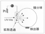
- FIG. 3 is a diagram showing Tafel plots of ⁇ -MnO 2 on FTO and carbon paper. It is a figure which shows the outline of the experimental mechanism for in-situ @ UV-Vis measurement. The working electrode was placed immediately before the detector window, and the reference and counter electrodes were placed adjacent to the electrochemical cell wall.
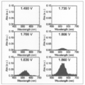
- FIG. 4 shows the UV / Vis absorption spectrum of the electrolyte one hour after electrolysis at the indicated potential. The measurements are for ⁇ -MnO 2 on FTO at pH 2.
- FIG. 4 is a diagram showing the time dependence of the anode potential during electrolysis at a constant current density of 10 mAcm ⁇ 2 (curve a) and 100 mAcm ⁇ 2 (curve b). The measurements are for ⁇ -MnO 2 on FTO at pH 2.
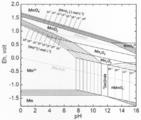
- FIG. 4 is a Pourbaix diagram of a Mn—H 2 O system calculated using the CHNOSZ package [see Reference 19].
- the free energy of formation ( ⁇ G0) used was ⁇ 465.MnO 2 , Mn 2+ , MnO 4 ⁇ , MnO 4 2 ⁇ , Mn 2 O 3 , Mn 3 O 4 , Mn (OH) 2 and Mn, respectively. 15 kJmol -1 , -227.76 kJmol -1 , -449.66 kJmol -1 , -504.09 kJmol -1 , -888.857 kJmol -1 , -1281.16 kJmol -1 , -615.04 kJmol -1 and 0 kJmol -1 there were.
- FIG. 3 is a schematic view showing a procedure for preparing an anode ( ⁇ -MnO 2 / carbon paper). It is a figure which shows the outline of the structure of a PEM electrolysis apparatus. It is a photograph which shows a PEM water electrolysis system. Electrolysis was performed using a single stack PEM water electrolyzer cell. Milli-Q ultrapure water was pressed into the anode part of the electrolyzer.
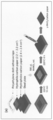
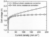
- FIG. 4 shows a linear sweep voltammogram of ⁇ -MnO 2 on carbon paper at 25 ° C. It is a graph showing the time dependence of the cell voltage at 10MAcm 2 and 100mAcm 2 (25 °C, no ohmic resistance correction). 4 is a graph showing the stability of spinel-type cobalt manganese oxide Co 3-X MnXO 4 at pH 1 and 100 mAcm ⁇ 2 .
- FIG. 4 is a graph showing the stability of Co 2 MnO 4 in H 2 SO 4 (pH 1) and H 3 PO 4 (pH 1) at 100 mAcm ⁇ 2 .
- FIG. 3 is a graph showing the stability of ⁇ -MnO 2 in H 2 SO 4 (pH 1, pH 2) and H 3 PO 4 (pH 1) at 100 mAcm ⁇ 2 .
- FIG. 4 is a graph showing that the use of H 3 PO 4 as an electrolyte significantly improved the stability of ⁇ -MnO 2 at 100 mAcm ⁇ 2 .
- FIG. 3 is a schematic diagram showing chemical species derived from ⁇ -MnO 2 generated during an OER cycle under acidic conditions and its side reaction.
- a water electrolysis apparatus comprising: an oxidation catalyst containing at least one first transition metal on at least a part of the surface of the anode; P2 is the lowest potential at which oxygen is generated, and P2 indicates the lowest potential P2 at which the quantitative index of the dissolved species derived from the oxidation catalyst starts to show potential dependence.
- the anode is connected to the positive electrode of the power supply unit, means an electrode that causes an oxidation reaction and generates oxygen in the electrolysis of water, and has at least a part of the surface of the first transition metal.
- an oxidation catalyst comprising at least one.
- the first transition metal (3d transition metal) according to the present invention is not particularly limited, and includes, for example, manganese, iron, cobalt, and nickel. Manganese is preferred from the viewpoint of simplicity.
- the oxidation catalyst used in the present invention may not contain a noble metal, and even if it does contain a noble metal, the oxidation catalyst may have a molar ratio of noble metal to the total molar ratio of all metals in the catalyst. The ratio may be 10% or less, 5% or less, 1% or less, 0.1% or less, or 0.
- the oxidation catalyst according to the present invention may contain an oxide or a hydroxide of the first transition metal, for example, manganese oxide (2+, 3+, 4+), iron oxide (2+, 3+), hydroxide At least one metal oxide or metal hydroxide selected from cobalt (2+, 3+) and nickel oxide (2+, 3+, 4+).
- an oxide or a hydroxide of the first transition metal for example, manganese oxide (2+, 3+, 4+), iron oxide (2+, 3+), hydroxide
- Examples of the compound containing manganese include manganese ore ( ⁇ -MnO 2 ), ramsdel ore (RMnO 2 ), and enuta ore ( ⁇ -MnO 2 ) [see Reference 25].
- the oxidation catalyst according to the present invention preferably contains ⁇ -MnO 2 .
- the oxidation catalyst according to the present invention may be a composite oxide or a composite hydroxide of a plurality of types of first transition metals.
- the plurality of types of first transition metal oxides or hydroxides include a composite oxide of cobalt and manganese (eg, a spinel-type cobalt manganese oxide), and more specifically, Co 3-x Mn x O 4 (Co 0.1 Mn 0.9 O 4 , CoMn 2 O 4 , Co 1.5 Mn 1.5 O 4 , Co 2 MnO 4 ), among which higher stability. It is preferable that Co 2 MnO 4 is included in the oxidation catalyst according to the present invention from the viewpoint of easily exhibiting properties.
- the embodiment using the manganese oxide as the catalyst is determined by the method of the present invention.
- the width of the potential window that can be driven stably can be widened (more specifically, the upper limit potential P2 of the potential window can be increased).
- the form of the oxidation catalyst of the present invention is not particularly limited, but may usually be in the form of a catalyst supported on an anode (support).
- the carrier for supporting the catalyst include conductive ceramics such as FTO (fluorine-doped tin oxide) and ITO (indium tin oxide), metals such as nickel and platinum, and carbons such as acetylene black and Ketjen black. Carbon material).
- the method for preparing the catalyst of the present invention is not particularly limited, and the catalyst of the present invention can be easily prepared by a known method.
- Examples of the method for supporting the catalyst of the present invention on a carrier include a thermal decomposition method, a spray method, a kneading method, an impregnation method, an adsorption method, and an ion exchange method.
- the oxidation catalyst may be present on at least a part of the surface of the carrier (anode), and may be, for example, 10% or more, 20% or more, 30% or more, 40% or more, 50% or more of the surface.
- the oxidation catalyst may be present at 60% or more, 70% or more, 80% or more, 90% or more, and 100%.
- the specific surface area of the catalyst of the present invention is not particularly limited, but is usually 5 to 200 m 2 / g, preferably 10 m 2 / g or more, more preferably 20 m 2 / g or more, and further preferably 50 m 2 / g or more. 2 / g or more, more preferably 70 m 2 / g or more.
- a BET Brunauer-Emett-Teller
- the catalyst of the present invention may appropriately contain components other than the above-mentioned first transition element, base and carbonate.
- a component include a polymer electrolyte such as a perfluorosulfonic acid polymer (NAFION (trade name)) and a conductive carbon material such as acetylene black and Ketjen black.
- the cathode may be any electrode that is connected to the cathode of the power supply unit and that generates a reduction reaction and generates hydrogen in water electrolysis, such as a platinum electrode.
- the solid polymer electrolyte membrane disposed between the anode and the cathode is a membrane composed of a water-insoluble polymer electrolyte, and may be any membrane that is also called an ion exchange membrane. Examples of such a polymer electrolyte include a perfluorosulfonic acid polymer (NAFION (trade name) and the like).
- NAFION perfluorosulfonic acid polymer
- the water supplied to the electrolysis cell and electrolyzed may be water alone (so-called pure water) or may be in the form of an aqueous solution containing an electrolyte or the like.
- an electrolyte include a phosphate ion, a sulfate ion, a carbonate ion, an arsenate ion, a phosphite ion, a silicate ion, and a borate ion.
- the stability of the first transition metal is improved. From the viewpoint of easy increase, phosphate ions and sulfate ions are preferred, and phosphate ions are more preferred.
- the width of the potential window that can be driven stably determined by the method of the present invention can be widened (more specifically, the upper limit potential P2 can be increased).
- the pH of water is not particularly limited, it is usually acidic near the anode.
- Such acidic conditions include, for example, less than pH 7 (pH 6, pH 5, pH 4, pH 3, pH 2, pH 1).
- a potential is applied between the anode and the cathode to electrolyze water.
- this potential (P) is adjusted to satisfy a predetermined range, and the range (P1 ⁇ P ⁇ P2) is , Can be determined by a method described later.
- the "control unit for controlling the potential to P satisfying P1 ⁇ P ⁇ P2" provided in the water electrolysis apparatus of the present invention is provided by inputting P1 and P2 predetermined by a method described later. Any device can be used as long as it can adjust the potential to be applied, and examples thereof include a potentiostat and a potential programmer. Further, the water electrolysis apparatus of the present invention further comprises a measuring means for measuring a quantitative index of a dissolved chemical species described below in-situ, wherein the control means adjusts a value of the quantitative index detected by the measuring means. Based on this, P may be controlled. As such an in-situ measuring means, for example, there is a UV-Vis spectrometer used for in-situ spectroscopy described later.
- the present inventors efficiently promote the oxygen generation reaction (OER) by using a catalyst containing the first transition metal, and at the same time, can suppress the inactivation pathway of the metal. Was found to exist. Therefore, the present invention provides the following method for determining the driving potential.
- a method for determining a driving potential P of an electrolytic cell for water electrolysis comprising a solid polymer electrolyte membrane, an anode having an oxidation catalyst containing at least one first transition metal, and a cathode, wherein the anode From which oxygen begins to evolve, predetermining the lowest potential P1 between the anode and the cathode, the quantitative index of the dissolved species derived from the electrocatalyst begins to show potential dependence, between the anode and the cathode
- a method comprising: determining the minimum potential P2 in advance; and determining the drive potential P to a value satisfying a condition of P1 ⁇ P ⁇ P2.
- the "minimum potential P1 between the anode and the cathode, at which oxygen starts to be generated from the anode,” refers to the type of oxidation catalyst used by those skilled in the art, the type of water, the type of electrolyte contained therein, and the pH of water. Can be determined appropriately using a known method. As such a known method, as shown in Examples described later, while changing the applied potential, the amount of oxygen generated in the electrolytic cell for electrolysis is measured by using a thermal conductivity detector (TCD) and / or A method of detecting by gas chromatography is exemplified.
- TCD thermal conductivity detector
- the "quantitative index of the dissolved species derived from the oxidation catalyst" is the It is only necessary to reflect the amount of the chemical species dissolved (eluted) from the oxidation catalyst, such as the intensity of the absorption peak attributed to the chemical species. Whether the intensity or the like of the absorption peak starts to show potential dependence is determined by, for example, in-situ spectroscopy (more specifically, in-situ UV / Vis spectroelectrochemical measurement) as described in Examples below. Is mentioned.
- the driving potential P obtains a first curve obtained by plotting the amount of oxygen generated from the anode with respect to the potential between the anode and the cathode, and obtains a value of the dissolved chemical species derived from the oxidation catalyst.
- the quantitative index can be determined based on a second curve obtained by plotting a second curve plotted against the potential between the anode and the cathode and comparing the first curve with the second curve.
- FIG. 8 schematically shows changes in ⁇ -MnO 2 generated during the OER cycle under acidic conditions and its side reaction.
- the solid line indicates the OER cycle.
- dashed line, the dissolution / redeposition manganese oxide, disproportionation of Mn III, and MnO4 - shows a side reaction species and the like.
- the potential in the figure is a value determined by the above method.
- the species circled in gray are considered stable on the ⁇ -MnO 2 electrode.
- ⁇ -MnO 2 was produced directly on a glass (SPD Research Laboratories, Inc.) coated with fluorinated tin oxide (FTO) by a pyrolysis method [see Reference 18]. That is, 0.5 mL of 4M Mn (NO 3 ) 2 (JIS reagent special grade, ⁇ 98.0%, Sigma-Aldrich) was dropped on clean FTO-coated glass, and was heated at 220 ° C. for 6 hours by a hot plate in air. Fired. The addition of Mn was controlled by the number of dropping / firing cycles.
- 4M Mn (NO 3 ) 2 JIS reagent special grade, ⁇ 98.0%, Sigma-Aldrich
- the obtained electrode was washed with Milli-Q ultrapure water (18.2 M ⁇ cm at 25 ° C., Merck Millipore) and decomposed with ultrasonic waves for 10 seconds. Finally, before the measurement, the electrodes were dried in an oven at 40 ° C. for several hours.
- ⁇ -MnO 2 was produced on hydrophilic carbon paper (HGP-H-060, thickness 190 ⁇ m, Toray).
- HGP-H-060 thickness 190 ⁇ m, Toray.
- a hydrophilic carbon paper 2.2 ⁇ 2.2 cm 2, 2.4 hydrophobic carbon paper ⁇ 2.4cm 2 (EC-TP1-060T, Teflon (registered trademark ) Treated, 190 ⁇ m thick, placed at the center of Toray).
- Teflon registered trademark
- hydrophilic carbon paper and hydrophobic carbon paper were attached at the center of a stainless steel sample holder.
- the composition was pretreated on a hot plate for 10 minutes at 220 ° C.
- XPS was performed using a surface analyzer (PHI 5000 Versa Probe II, ULVAC-PHI). Monochrome Al @ K ⁇ (1486.6 eV) irradiation was used for all XPS measurements.
- TEM images were acquired using a Hitachi HT7700 microscope.
- the sample suspension was dropped onto a copper grid and dried in air.
- HRTEM images were acquired at 200 kV using a JEM-2100 microscope.
- HRTEM sample the sample suspension was dropped on a lacy carbon support and dried in air.
- the surface area and pore structure of the present manganese oxide were examined by measuring the nitrogen adsorption / desorption isotherm at liquid nitrogen temperature (77 K) using a surface area analyzer (Micromeritics ASAP2000 apparatus). The sample was degassed at 373K for 9 hours before measurement.
- the specific surface area of manganese oxide was estimated to be 71.2 m 2 g ⁇ 1 based on the Brunauer-Emmett-Teller (BET) equation [see Reference 19].
- BET Brunauer-Emmett-Teller
- the adsorption average pore width of manganese oxide was estimated to be 10.3 nm based on fitting analysis using the Barrett-Joyner-Halenda (BJH) method [see Reference 20].
- the electrochemical behavior of ⁇ -MnO 2 was evaluated in a three-electrode electrochemical cell using 30 mL of electrolyte.
- the electrodes were pretreated with a sulfuric acid solution (1.0 MH 2 SO 4 ) (Wako Pure Chemical Industries, Ltd.) for 2 hours at a current density of 10 mAcm ⁇ 2 .
- the current density (j) vs. potential (U) curve was measured using a Pt wire (99.98%, PT-351325, ⁇ 0.30 mm, Nilaco) in 1.0 MH 2 SO 4 as a counter electrode using Ag / AgCl.
- KCl saturated KCl, World Precision Instruments
- HZ-5000 Hokuto Denko
- a sweep rate of 1 mVs- 1 at room temperature (25 ⁇ 2 ° C.).
- a sulfuric acid electrolyte containing 0.5 M Na 2 SO 4 was used as a supporting electrolyte.
- the iR correction values of the working electrode and the reference electrode were measured by electrochemical impedance spectroscopy (i, current; R, resistance).
- the electrode potential after iR correction was rescaled to a reversible hydrogen electrode (RHE).
- UV-Vis absorption spectra were obtained using a UV-Vis spectrometer (UV-2550, Shimadzu) in diffuse transmission mode with a built-in integrating sphere (MPC-2200, Shimadzu).
- a manganese oxide thin film electrode attached to a quartz electrochemical cell (2 cm ⁇ 2 cm ⁇ 2.5 cm height) filled with 7 mL of electrolyte was placed just before the integrating sphere.
- a membrane-electrode assembly was prepared using a Nafion® 117 polymer membrane (DuPont, 177.8 ⁇ m thick, N117). Prior to making the MEA, the N117 membranes were boiled for 1 hour each in the following solutions to remove possible contaminants and to ensure complete membrane protonation. First 3 wt% H 2 O 2 , then Milli-Q ultrapure water, then 1.0 MH 2 SO 4 , and finally again Milli-Q ultrapure water. Finally, the N117 membrane was dried in an oven at 40 ° C. for several hours before use.
- MEAs were made using Pt as the cathode for the hydrogen evolution reaction and MnO 2 as the anode for the oxygen evolution reaction.
- a Pt slurry is mixed with Pt / C (20 wt% Pt in carbon black, Fuel Cell Earth), water, ethanol, and Nafion (registered trademark) solution (5 wt% in H 2 O, Sigma-Aldrich) as a binder.
- Pt / C (20 wt% Pt in carbon black, Fuel Cell Earth
- water ethanol
- Nafion (registered trademark) solution (5 wt% in H 2 O, Sigma-Aldrich) as a binder.
- Produced by And left to dry the catalyst ink mixture was fed to hydrophobic east Rekabon paper mass feed rate of each 0.1Mgcm -2 and 0.03Mgcm -2 for Pt and Nafion®, in a few hours 40 ° C. in an oven I let it.
- MnO 2 / carbon paper was produced with a manganese supply of 3.5 ⁇ 0.5 mgcm ⁇ 2 as described in the item “Generation of ⁇ -MnO 2 on carbon paper substrate” above. After deposition of the catalyst material, the surface was coated with an additional amount of Nafion (R) (respectively the cathode and the anode, 0.6Mgcm -2 and 1.0mgcm -2). Both the obtained Pt / carbon and MnO 2 / carbon samples were left to dry in an oven at 40 ° C. for several hours. Thereafter, Pt / carbon paper and MnO 2 / carbon paper were thermocompression-bonded to both sides of a commercially available N117 film at 135 ° C. with a mold clamping force of 5 MPa for 10 minutes to produce an MEA. The effective area of the MEA was 2 cm ⁇ 2 cm (4 cm 2 ).
- the electrolysis test was performed using a single cell PEM electrolyzer (FC-R & D, PEM-3036, Kanagawa, Japan). Stainless steel mesh was used as a gas diffusion layer for both the anode and cathode.
- ⁇ -MnO 2 is well known as a cathode material for dry cells, and its industrial scale synthesis has historically been performed in concentrated sulfuric acid (pH ⁇ 1), suggesting the inherent chemical stability in acidic environments. [Ref. 9].
- ⁇ -MnO 2 was generated on a fluorine-containing tin oxide (FTO) or carbon-based substrate by thermally decomposing manganese nitrate at 220 ° C. in air.
- FTO fluorine-containing tin oxide
- TEM transmission electron microscopy
- a striking structural feature of ⁇ -MnO 2 is the intergrowth of the manganese ore ( ⁇ -MnO 2 composed of symmetric octahedral units) phase and the Ramsdel ore (R-MnO 2 ) composed of symmetric octahedral units.
- HRTEM transmission electron microscopy
- FIG. 1B From the division of the XRD peaks of the (110) and (130) planes (FIG. 1B) and the Raman shift of the Mn—O stretching vibration in the region of 400 to 800 cm ⁇ 1 (FIG. 1C), the ratio of the manganese ore (Pr ) Is about 70% [see references 9b, 11].
- ⁇ -MnO 2 The electrochemical behavior of ⁇ -MnO 2 was evaluated by linear sweep voltammetry (LSV) in 1.0 M sulfuric acid at a potential sweep rate of 1 mVs ⁇ 1 (FIGS. 2A and B).
- LSV linear sweep voltammetry
- ⁇ -MnO 2 required an overvoltage of 489 ⁇ 5 mV to reach a current density (geometric area) of 10 mAcm ⁇ 2 on the FTO substrate.
- Example 2 It is well known that manganese oxide dissolves during water electrolysis, especially under acidic conditions. Materials that are reported to be stable, such as electrodeposited manganese oxide, show a noticeable increase in overvoltage in a short time at relatively low current densities (less than 1 mAcm ⁇ 2 ) [see references 12a, b]. ]. Manganese leaching was also observed in manganese oxide doped with titanium and in the ternary oxide Ni 0.5 Mn 0.5 Sb 1.7 O y [see references 7d and 7b]. Currently, there are no reports of Mn oxides stable under OER conditions in acidic electrolytes over a period of several months.
- FIG. 3C shows how potential affects the activity and stability of ⁇ -MnO 2 as an OER catalyst. Scanning the potential to the positive side produces Mn 3+ at 1.4 V, characterized by a 480 nm peak in the UV / Vis spectrum of the electrode [14]. The generation of this intermediate leads to the onset of the OER current at 1.6 V, like other Mn oxides [see References 13 and 16]. Most notably, there is a third potential dependent process that is noticeable from 1.8V. This process is the occurrence of an MnO 4 ⁇ absorption peak in the UV / Vis spectrum of the electrolyte, indicating that the major dissolution path of the MnO 2 electrode is via MnO 4 ⁇ .
- the present inventors performed water electrolysis at a constant current density in order to explore the possibility of acid-stable MnO 2 (FIGS. 5A to 5C).
- the electrode potential of the electrolysis was about 1.73 V vs. 10 mAcm -2 at a current density of about 1.73 Vvs. RHE. This is MnO 4 - lower than at the start of the occurrence.
- the catalyst showed no apparent loss of activity after more than 8000 hours of operation (> 11 months), demonstrating the surprising stability of ⁇ -MnO 2 under these electrochemical conditions (FIG. 3D, curve a). Long-term water electrolysis was also confirmed at pH1.
- Example 4 Cobalt-manganese oxide layers were formed on FTO substrates ( ⁇ 7 ⁇ sq ⁇ 1 , manufactured by SPD Laboratory, Inc.) with various changes in the molar ratio of Co to Mn. Specifically, it is as follows.
- cleaning step This was rinsed with Milli-Q water (18.2 M ⁇ cm at 25 ° C., obtained from Merck Millipore) and ultrasonically cleaned for 10 seconds to remove particles such as impurities lightly adhered to the surface (hereinafter referred to as “cleaning step”). .).
- cleaning step The above drop casting step, baking step, and washing step were repeated again to form a layer that completely covered the FTO substrate surface.
- the electrode substrate was dried in an oven at 40 ° C. for several hours.
- the obtained layer was composed of a spinel-type cobalt manganese oxide having a Co / Mn molar ratio of 2: 1 (hereinafter, this layer was referred to as “Co 2 MnO 4 layer”). Express). Thus, an FTO electrode with a Co 2 MnO 4 layer was produced.
- X-ray diffraction (XRD) pattern of the layer formed above was measured.
- a fully automatic multipurpose X-ray diffractometer SmartLab (Rikagaku Co., Ltd.) was used for the measurement. The measurement was performed at a scan speed of 0.5 ° / min at a scan speed of 0.5 ° / min and every 0.01 ° within a range of 10-80 ° (2 ⁇ ). From the obtained XRD pattern, it was understood that the obtained cobalt manganese oxide formed a crystal system having a cubic spinel structure.
- X-ray photoelectron spectroscopy (XPS) of the prepared catalyst layer was measured using a ULVAC-PHI spectrometer (PHI 5000sVersa Probe II) equipped with an AlK ⁇ (1486.6 eV) irradiation device.
- XPS X-ray photoelectron spectroscopy
- the XPS measurement results show that both Co 2+ and Co 3+ exist, the average valence is about 2.5, and that both Mn 3+ and Mn 4+ exist, and the average valence is about 3.6.
- Co 2+ are present in tetrahedral sites
- Mn x + and Co 3+ are present in octahedral sites.
- x was about 3.6 and ⁇ was about 0.3, which was consistent with the previously reported value of cobalt manganese spinel oxide having a Co / Mn ratio of 2: 1.
- Precursor solutions were prepared at molar ratios of Co to Mn of 1: 1, 1: 2, and 1: 9, respectively, and Co 1.5 Mn 1 was prepared in the same manner as above except that each precursor solution was used.
- a 0.5 O 4 layer, a CoMn 2 O 4 layer, and a Co 0.1 Mn 0.9 O 4 layer were formed on the FTO, respectively.
- an FTO electrode with a Co 1.5 Mn 1.5 O 4 layer, an FTO electrode with a CoMn 2 O 4 layer, and an FTO electrode with a Co 0.1 Mn 0.9 O 4 layer were respectively produced.
- OER catalytic stability under strong acidity The stability of the oxygen generation reaction (OER) catalytic ability of each layer under strong acidity was evaluated by performing chronopotentiometry measurement. The details are as follows.
- HZ-7000 a commercially available three-electrode potentiostat
- the counter electrode was a Pt wire electrode (99.98%, PT-351225, ⁇ 0.30 mm, manufactured by Nilaco)
- the reference electrode was Ag / AgCl (3.5 M KCl, manufactured by World Precision Instruments, 0.205 Vvs. NHE). at 25 ° C.).
- the current density was calculated based on the area (0.28 cm 2 ) of the FTO substrate exposed to the electrolyte. In addition, all the measurements were performed at a temperature of 25 ° C.
- FIG. 7A also shows a curve extracted from an FTO electrode with a Co 2 MnO 4 layer.
- FIG. 7A also shows a curve extracted from an FTO electrode with a ⁇ -MnO 2 layer.
- the oxidation catalyst containing the first transition metal can stably electrolyze water.
Abstract
固体高分子電解質膜、及びそれを挟持して配置されたアノード及びカソードを備えた電気分解セル中に、少なくとも水を供給すること、前記アノード及びカソード間に電位Pを供与して、アノードから酸素を発生させること、を含む水の電気分解方法であって、前記アノードの表面の少なくとも一部に、第一遷移金属の少なくとも1種を含む酸化触媒が存在し、電位Pが、P1<P<P2を満足する、水の電気分解方法(但し、P1は、前記アノードから酸素が発生する最低電位を示し、P2は、前記酸化触媒由来の溶解化学種の量的指標が電位依存性を示し始める最低電位P2を示す)。
Description
本発明は、水の電気分解方法及び水電気分解装置に関する。また、本発明は、水電気分解における駆動電位を決定する方法に関する。
再生可能エネルギーを利用する効率的な技術の開発は、増大するエネルギー需要を満たすためには重要である。水電解 (2H2O→2H2+O2)により生成される水素は、再生可能エネルギーを保存するための理想的なエネルギー担体であるばかりか、アンモニア合成等の化学産業における重要な原料でもある。
水電解で特に期待できる機構は、プロトン交換膜(PEM)電解装置である。しかしながら、PEMは局所的に酸性環境を作り出す。そのため、酸素発生反応(OER;2H2O→O2+4H++4e-)に対して安定的な触媒活性を維持する触媒は、イリジウム由来の酸化物であるが、イリジウムは地球の地殻中最も希少な元素の一つである。例えば、イリジウム酸化物の触媒を用いて、テラワット規模でPEM電解装置を使用しようとすると、年間イリジウム生産量の10倍超が必要になる。このことを考慮すると、酸安定な非貴金属のOER触媒を開発することが、PEM電解装置での水電解において重要な課題と言える。
広いpH範囲に亘って使用可能な3d遷移金属系OER触媒を開発するために広範囲の研究が行われている。しかしながら、多くの実験研究によって、豊富な金属(鉄やコバルト、ニッケル、マンガン)の酸化物は、酸性媒体に対するそれらの溶解性のために不安定であることが示されている(非特許文献1~6)。それらの安定性の欠如は、現状安定した材料を合理的に特定する一般的な方法がないことから、特に喫緊の課題である。他方、dバンド理論によって3d遷移金属(第一遷移金属)触媒の活性を予測し選別することが可能なことが証明されている(非特許文献7)。
C.C.McCrory,S.Jung,I.M.Ferrer,S.M.Chatman,J.C.Peters,T.F.Jaramillo,J.Am.Chem.Soc.2015,137,4347-4357
M.Pourbaix,Atlas of electrochemical equilibria in aqueous solutions,Pergamon,New York,1966,pp.286-292
I.A.Moreno-Hernandez,C.A.MacFarland,C.G.Read,K.M.Papadantonakis,B.S.Brunschwig,N.S.Lewis,Energy Environ.Sci.2017,10,2103-2108
J.S.Mondschein,J.F.Callejas,C.G.Read,J.Y.C.Chen,C.F.Holder,C.K.Badding,R.E.Schaak,Chem.Mater.2017,29,950-957
R.Frydendal,E.A.Paoli,I.Chorkendorff,J.Rossmeisl,I.E.L.Stephens,Adv.Energy Mater.2015,5,1500991
M.Huynh,T.Ozel,C.Liu,E.C.Lau,D.G.Nocera,Chem.Sci.2017,8,4779-4794
J.K.Norskov,T.Bligaard,J.Rossmeisl,C.H.Christensen,Nat.Chem.2009,1,37-46
本発明は、前記従来技術の有する課題に鑑みてなされたものであり、3d遷移金属(第一遷移金属)を含む酸化触媒が、安定して水を電気分解することを可能とする方法を提供することを目的とする。
本発明者らは、前記目的を達成すべく鋭意研究を重ねた。その結果、第一遷移金属の酸化物等によってOERを効率的に促進すると同時に、当該金属酸化物等の触媒の失活経路を抑制できる、駆動電位が安定した電位窓があることを見出し、本発明を完成するに至った。
すなわち、本発明は、第一遷移金属を含む酸化触媒が安定して水を電気分解することを可能とする方法及び装置に関する。また、第一遷移金属を含む酸化触媒が安定して水を電気分解することを可能とする、駆動電位を決定する方法に関し、より具体的には以下のとおりである。
<1> 固体高分子電解質膜、及びそれを挟持して配置されたアノード及びカソードを備えた電気分解セル中に、少なくとも水を供給すること、前記アノード及びカソード間に電位Pを供与して、アノードから酸素を発生させること、を含む水の電気分解方法であって、前記アノードの表面の少なくとも一部に、第一遷移金属の少なくとも1種を含む酸化触媒(例えば、第一遷移金属の酸化物もしくは水酸化物であり、単一の第一遷移金属の酸化物もしくは水酸化物であってもよく、又は2種以上の第一遷移金属の複合酸化物もしくは複合水酸化物であってもよく、好ましくは、単一の第一遷移金属の酸化物又は2種以上の第一遷移金属の複合酸化物である。)が存在し、電位Pが、P1<P<P2を満足する、水の電気分解方法(但し、P1は、前記アノードから酸素が発生する最低電位を示し、P2は、前記酸化触媒由来の溶解化学種の量的指標が電位依存性を示し始める最低電位P2を示す)。
<2> P1及びP2をそれぞれあらかじめ測定することを含む、<1>に記載の方法。
<3> 固体高分子電解質膜と、第一遷移金属の少なくとも1種を含む酸化触媒を有するアノードと、カソードとを備えた水の電気分解用電解セルの駆動電位Pを決定する方法であって、前記アノードから酸素が発生し始める、前記アノード及び前記カソード間の最低電位P1をあらかじめ決定すること、前記酸化触媒由来の溶解化学種の量的指標が電位依存性を示し始める、前記アノード及び前記カソード間の最低電位P2をあらかじめ決定すること、駆動電位PをP1<P<P2の条件を満足する値に決定することを含む、方法。
<4> 固体高分子電解質膜と、第一遷移金属の少なくとも1種を含む酸化触媒(例えば、第一遷移金属の酸化物もしくは水酸化物であり、単一の第一遷移金属の酸化物もしくは水酸化物であってもよく、又は2種以上の第一遷移金属の複合酸化物もしくは複合水酸化物であってもよく、好ましくは、単一の第一遷移金属の酸化物又は2種以上の第一遷移金属の複合酸化物である。)を有するアノードと、カソードとを備えた水の電気分解用電解セルの駆動電位Pを決定する方法であって、前記アノードからの酸素発生量を、前記アノード及び前記カソード間の電位に対してプロットした第1の曲線を取得すること、前記酸化触媒由来の溶解化学種の量的指標を、前記アノード及び前記カソード間の電位に対してプロットした第2の曲線を取得すること、前記第1の曲線と第2の曲線との対比に基づいて、駆動電位Pを決定すること、
を含む、方法。
<5> 前記量的指標が、前記化学種に帰属される吸収ピークの強度Iである、<1>~<4>のうちのいずれか一項に記載の方法。
<6> 前記第一遷移金属が、マンガン、鉄、コバルト及びニッケルから選ばれる少なくとも1種の金属である、<1>~<4>のうちのいずれか一項に記載の方法。
<7> 前記酸化触媒が、第一遷移金属から選ばれる少なくとも1種の酸化物又は水酸化物である、<1>~<4>のうちのいずれか一項に記載の方法。
<8> 前記酸化触媒が、酸化マンガン(2+、3+、4+)、酸化鉄(2+、3+)、水酸化コバルト(2+、3+)及び酸化ニッケル(2+、3+、4+)から選ばれる少なくとも1種の金属酸化物又は金属水酸化物である、<1>~<4>のうちのいずれか一項に記載の方法。
<9> 前記酸化触媒が、酸化マンガンであり、水素電極(RHE)に対してPが1.65V<P<1.75Vを満足する、<1>~<4>のうちのいずれか一項に記載の方法。
<10> 固体高分子電解膜と、前記固体高分子電解膜を挟持して配置されるアノード及びカソードと、前記アノード及びカソード間に電位を与える電源部と、前記電位をP1<P<P2を満足するPに制御する制御部と、を備えた水電気分解装置であって、前記アノードの表面の少なくとも一部に、第一遷移金属の少なくとも1種を含む酸化触媒(例えば、第一遷移金属の酸化物もしくは水酸化物であり(単一の第一遷移金属の酸化物もしくは水酸化物であってもよく、又は2種以上の第一遷移金属の複合酸化物もしくは複合水酸化物であってもよく、好ましくは、単一の第一遷移金属の酸化物又は2種以上の第一遷移金属の複合酸化物である。)が存在し、P1は、前記アノードから酸素が発生する最低電位であり、且つP2は、前記酸化触媒由来の溶解化学種の量的指標が電位依存性を示し始める最低電位P2を示す、水電気分解装置。
<11> P1及びP2があらかじめ入力された値である、<10>に記載の装置。
<12> 前記酸化触媒由来の溶解化学種の量的指標をin-situで測定する測定手段をさらに備え、前記制御手段が、前記測定手段が検出した量的指標の値に基づいて、Pを制御する、<10>に記載の装置。
<13> 前記量的指標が、前記化学種に帰属される吸収ピークの強度Iである、<10>に記載の装置。
<14> 前記第一遷移金属が、マンガン、鉄、コバルト及びニッケルから選ばれる少なくとも1種の金属である、<10>に記載の装置。
<15> 前記酸化触媒が、第一遷移金属から選ばれる少なくとも1種の酸化物又は水酸化物である、<10>に記載の装置。
<16> 前記酸化触媒が、酸化マンガン(2+、3+、4+)、酸化鉄(2+、3+)、水酸化コバルト(2+、3+)及び酸化ニッケル(2+、3+、4+)から選ばれる少なくとも1種の金属酸化物又は金属水酸化物である、<10>に記載の装置。
<17> 前記酸化触媒が、酸化マンガンであり、水素電極(RHE)に対してPが1.65V<P<1.75Vを満足する、<10>に記載の装置。
<18> 固体高分子電解膜と、前記固体高分子電解膜を挟持して配置されるアノード及びカソードと、前記アノード及びカソード間に電位を与える電源部と、前記電位をP1<P<P2を満足するPに制御する制御部と、を備えた水電気分解装置であって、前記アノードの表面の少なくとも一部に、コバルトとマンガンとのスピネル型複合酸化物を含む酸化触媒が存在し、P1は、前記アノードから酸素が発生する最低電位であり、且つP2は、前記酸化触媒由来の溶解化学種の量的指標が電位依存性を示し始める最低電位P2を示す、水電気分解装置。
<19> 固体高分子電解膜と、前記固体高分子電解膜を挟持して配置されるアノード及びカソードと、前記アノード及びカソード間に電位を与える電源部と、を備えた水電気分解装置であって、前記アノードの表面の少なくとも一部に、コバルトとマンガンとのスピネル型複合酸化物を含む酸化触媒が存在する、水電気分解装置。
本発明によれば、第一遷移金属を含む酸化触媒により、安定して水を電気分解することが可能となる。例えば、後述の実施例に示すとおり、本発明によれば、γ-MnO2が、顕著な活性の低下なくpH2電解質中で8000時間超に亘って10mAcm-2で酸素発生反応を促進することができる。
(水の電気分解方法及び電気分解装置)
後述の実施例に示すとおり、本発明者らは、第一遷移金属を含む触媒によって酸素発生反応(OER)を効率的に促進すると同時に、当該金属の失活経路を抑制できる、駆動電位が安定した電位窓が存在することを見出した。本発明はかかる知見に基づき完成されたものであり、具体的には、下記水の電気分解方法及び電気分解装置を提供する。
後述の実施例に示すとおり、本発明者らは、第一遷移金属を含む触媒によって酸素発生反応(OER)を効率的に促進すると同時に、当該金属の失活経路を抑制できる、駆動電位が安定した電位窓が存在することを見出した。本発明はかかる知見に基づき完成されたものであり、具体的には、下記水の電気分解方法及び電気分解装置を提供する。
固体高分子電解質膜、及びそれを挟持して配置されたアノード及びカソードを備えた電気分解セル中に、少なくとも水を供給すること、前記アノード及びカソード間に電位Pを供与して、アノードから酸素を発生させること、を含む水の電気分解方法であって、前記アノードの表面の少なくとも一部に、第一遷移金属の少なくとも1種を含む酸化触媒が存在し、電位Pが、P1<P<P2を満足する、水の電気分解方法(但し、P1は、前記アノードから酸素が発生する最低電位を示し、P2は、前記酸化触媒由来の溶解化学種の量的指標が電位依存性を示し始める最低電位P2を示す)。
固体高分子電解膜と、前記固体高分子電解膜を挟持して配置されるアノード及びカソードと、前記アノード及びカソード間に電位を与える電源部と、前記電位をP1<P<P2を満足するPに制御する制御部と、を備えた水電気分解装置であって、前記アノードの表面の少なくとも一部に、第一遷移金属の少なくとも1種を含む酸化触媒が存在し、P1は、前記アノードから酸素が発生する最低電位であり、且つP2は、前記酸化触媒由来の溶解化学種の量的指標が電位依存性を示し始める最低電位P2を示す、
本発明において、アノード(陽極)は、電源部の正極に接続され、酸化反応が生じ、水の電気分解において酸素を発生させる電極を意味し、当該表面の少なくとも一部に、第一遷移金属の少なくとも1種を含む酸化触媒が存在する。
本発明において、アノード(陽極)は、電源部の正極に接続され、酸化反応が生じ、水の電気分解において酸素を発生させる電極を意味し、当該表面の少なくとも一部に、第一遷移金属の少なくとも1種を含む酸化触媒が存在する。
本発明にかかる第一遷移金属(3d遷移金属)としては特に制限はなく、例えば、マンガン、鉄、コバルト、ニッケルが挙げられるが、天然に豊富に存在すること、また触媒の耐久性、合成の簡便性の観点から、マンガンが好ましい。
また、本発明に用いられる酸化触媒は、貴金属を含んでいなくてもよく、含んでいる態様であっても、割合としては、触媒中の全金属のモル比の合計に対して貴金属のモル比は10%以下、5%以下、1%以下、0.1%以下、又は0であってもよい。
本発明にかかる酸化触媒は、第一遷移金属の酸化物又は水酸化物を含むものであっても良く、例えば、酸化マンガン(2+、3+、4+)、酸化鉄(2+、3+)、水酸化コバルト(2+、3+)及び酸化ニッケル(2+、3+、4+)から選ばれる少なくとも1種の金属酸化物又は金属水酸化物が挙げられる。
マンガンを含む化合物としては、例えば、軟マンガン鉱(β-MnO2)、ラムスデル鉱(RMnO2)、エヌスタ鉱(γ-MnO2)が挙げられる[引用文献25 参照]。軟マンガン鉱は、最も豊富に存在するマンガン鉱種の一つであり、その構造は、単位格子パラメータがa(β)=4.39(8)Å、b(β)=4.39(8)Å及びc(β)=2.87(3)Å[引用文献26 参照]の1×1トンネルフレームワークを形成するように角部を共有して結合された稜共有[MnO6]8面体の一本鎖で構成される。ラムスデル鉱は、比較的希な鉱物であり、その構造は、単位格子パラメータがa(R)=4.52(1)Å、b(R)=9.27(3)Å及びc(R)=2.86(4)Å[引用文献27 参照]の1×2トンネルフレームワークを形成するように2つの稜を共有する非対称[MnO6]の二本鎖で構成される。これらの中で、本発明にかかる酸化触媒はγ-MnO2を含むことが望ましい。
本発明にかかる酸化触媒は、複数種の第一遷移金属の複合酸化物又は複合水酸化物であっても良い。かかる複数種の第一遷移金属の酸化物又は水酸化物としては、例えば、コバルトとマンガンの複合酸化物(スピネル型コバルト・マンガン酸化物等)が挙げられ、より具体的にはCo3-xMnxO4(Co0.1Mn0.9O4、CoMn2O4、Co1.5Mn1.5O4、Co2MnO4)が挙げられるが、これらの中で、より高い安定性を示し易いという観点から、Co2MnO4が、本発明にかかる酸化触媒に含まれていることが好ましい。別の観点から、本態様によれば、即ち、マンガンにコバルトを複合化した複合酸化物を触媒に用いる態様では、マンガン酸化物を触媒している用いる態様において、本発明の方法により決定される安定駆動可能な電位窓の幅を、広げる(より具体的には、電位窓の上限電位P2を上げる)ことができる。
本発明の酸化触媒の形態としては特に制限はないが、通常、アノード(担体)に担持されている触媒の形態をとり得る。触媒を担持させる担体としては、例えば、FTO(フッ素ドープの酸化スズ)、ITO(酸化インジウムスズ)等の導電性セラミック、ニッケル、白金等の金属、アセチレンブラック、ケッチェンブラック等のカーボン(導電性炭素材料)が挙げられる。
本発明の触媒の調製方法は特に限定されず、本発明の触媒は、公知の方法により容易に調製することができる。また、担体に本発明の触媒を担持する方法としては、例えば、熱分解法、スプレー法、混練法、含浸法、吸着法、イオン交換法が挙げられる。また、酸化触媒は、担体(アノード)の表面の少なくともその一部において存在していればよく、例えば、その表面の10%以上、20%以上、30%以上、40%以上、50%以上、60%以上、70%以上、80%以上、90%以上、100%に酸化触媒は存在していればよい。
本発明の触媒の比表面積としては特に制限はないが、通常5~200m2/gであり、好ましくは10m2/g以上であり、より好ましくは20m2/g以上であり、さらに好ましくは50m2/g以上であり、より好ましくは70m2/g以上である。触媒の比表面積の測定方法としては、後述の実施例において示すとおり、窒素の吸着を解析するBET(Brunauer-Emett-Teller)法を採用することができる。
さらに、本発明の触媒においては、前述の第一遷移元素、塩基及び炭酸塩以外の成分を適宜含んでいてもよい。かかる成分としては、例えば、パーフルオロスルフォン酸ポリマー(ナフィオン(NAFION;商品名)等)等の高分子電解質、アセチレンブラック、ケッチェンブラック等の導電性炭素材料が挙げられる。
本発明において、カソード(陰極)は、電源部の陰極に接続され、還元反応が生じ、水電気分解において水素を発生させる電極であればよく、例えば、白金電極が挙げられる。また、アノード及びカソード間に配置される固体高分子電解質膜としては、水に不溶な高分子電解質から構成される膜であり、イオン交換膜とも称されるものであればよい。かかる高分子電解質としては、例えば、パーフルオロスルフォン酸ポリマー(ナフィオン(NAFION;商品名)等)が挙げられる。また、固体高分子電解質膜、及びそれを挟持して配置されたアノード及びカソードを備える電気分解セルとしては特に制限はなく、当該分野(特に、プロトン交換膜(PEM)電解)において公知のものが適宜用いられ得る。
本発明において、前記電気分解セルに供給され、電気分解される水としては、水のみ(いわゆる純水)であってもよいが、電解質等が含まれている水溶液の形態であってもよい。かかる電解質としては、リン酸イオン、硫酸イオン、炭酸イオン、ヒ酸イオン、亜リン酸イオン、ケイ酸イオン、ホウ酸イオンが挙げられるが、これらの中で、第1遷移金属の安定性をより高め易いという観点から、リン酸イオン、硫酸イオンが好ましく、リン酸イオンがより好ましい。特にリン酸イオンを用いると、本発明の方法によって決定される安定駆動可能な電位窓の幅を広げる(より具体的には、上限電位P2を上げる)ことができる。
また、水のpHとしては特に制限はないが、通常アノード付近は酸性となる。かかる酸性条件としては、例えば、pH7未満(pH6、pH5、pH4、pH3、pH2、pH1)が挙げられる。
通常水を電気分解するためにアノード及びカソード間に電位を供与するが、本発明において、この電位(P)は所定の範囲を満足させるよう調整され、また当該範囲(P1<P<P2)は、後述の方法にて決定することができる。
本発明の水電気分解装置に備えられる「前記電位をP1<P<P2を満足するPに制御する制御部」としては、後述の方法にて予め決定されたP1及びP2を入力することにより供与する電位を調整し得る装置であればよく、例えば、ポテンショスタット及び電位プログラマーが挙げられる。また、本発明の水電気分解装置は、後述の溶解化学種の量的指標をin-situで測定する測定手段を更に備え、前記制御手段が、前記測定手段が検出した量的指標の値に基づいて、Pを制御するものであってもよい。かかるin-situでの測定手段としては、例えば、後述のin-situ分光法に用いられる、UV-Vis分光計が挙げられる。
(駆動電位の決定方法)
後述の実施例に示すとおり、本発明者らは、第一遷移金属を含む触媒によって酸素発生反応(OER)を効率的に促進すると同時に、当該金属の失活経路を抑制できる、駆動電位が安定した電位窓が存在することを見出した。したがって、本発明は、当該駆動電位を決定する下記方法を提供する。
後述の実施例に示すとおり、本発明者らは、第一遷移金属を含む触媒によって酸素発生反応(OER)を効率的に促進すると同時に、当該金属の失活経路を抑制できる、駆動電位が安定した電位窓が存在することを見出した。したがって、本発明は、当該駆動電位を決定する下記方法を提供する。
固体高分子電解質膜と、第一遷移金属の少なくとも1種を含む酸化触媒を有するアノードと、カソードとを備えた水の電気分解用電解セルの駆動電位Pを決定する方法であって、前記アノードから酸素が発生し始める、前記アノード及び前記カソード間の最低電位P1をあらかじめ決定すること、前記電解触媒由来の溶解化学種の量的指標が電位依存性を示し始める、前記アノード及び前記カソード間の最低電位P2をあらかじめ決定すること、駆動電位PをP1<P<P2の条件を満足する値に決定することを含む、方法。
「前記アノードから酸素が発生し始める、前記アノード及び前記カソード間の最低電位P1」としては、当業者であれば用いる酸化触媒の種類、並びに水、それに含まれる電解質の種類、及び水のpH等に応じ、公知の方法を用い適宜決定することができる。かかる公知の方法としては、後述の実施例に示すように、供与する電位を変更しながら、前記電気分解用電解セル内に発生する酸素量を、熱伝導度型検出器(TCD)及び/又はガスクロマトグラフィーにて検出する方法が挙げられる。
前記酸化触媒由来の溶解化学種の量的指標が電位依存性を示し始める、前記アノード及び前記カソード間の最低電位P2に関し、「前記酸化触媒由来の溶解化学種の量的指標」とは、前記酸化触媒から溶解(溶出)する化学種の量を反映するものであればよく、例えば、前記化学種に帰属される吸収ピークの強度が挙げられる。また、当該吸収ピークの強度等が電位依存性を示し始めるかについては、後述の実施例に示すとおり、例えば、in situ分光法(より具体的には、in situ UV/Vis分光電気化学測定)が挙げられる。
本発明においてはまた、駆動電位Pは、前記アノードからの酸素発生量を、前記アノード及び前記カソード間の電位に対してプロットした第1の曲線を取得し、前記酸化触媒由来の溶解化学種の量的指標を、前記アノード及び前記カソード間の電位に対してプロットした第2の曲線を取得し、前記第1の曲線と第2の曲線との対比に基づいて決定することができる。
pH2でのFTO上のγ-MnO2における例(図3C)を用いて説明すると、γ-MnO2を含む酸化触媒が表面に存在する酸素発生量を、前記電位に対してプロットした第1の曲線(Oxygen evolution)は水素電極に対する電位(vs。RHE)が1.60Vで立ち上がり始める。一方、前記酸化触媒から溶解したMnO4
-に由来する吸収ピーク強度を、前記電位に対してプロットした第2の曲線は1.75Vで立ち上がり始める。したがって、当業者であれば、かかる曲線により、酸化触媒が酸化マンガンである場合に、駆動電位を、水素電極に対して1.60V~1.75V(好ましくは、1.65V~1.75V)に決定することができる。
なお、図8に、酸性条件でのOERサイクル及びその副反応中に生じる、γ-MnO2の変化を概略図として示した。図中、実線は、OERサイクルを示す。破線は、マンガン酸化物の溶解/再堆積、MnIIIの不均化、及びMnO4-化学種等の副反応を示す。図中の電位は、上記方法で決定した値である。グレーの丸で囲んだ化学種がγ-MnO2電極上で安定であると考えられる。
また、後述の実施例に示すとおり、マンガン酸化物を触媒として用いた実験では、in-situ分析によって求められる安定駆動が可能な電位窓は、図4に示すマンガンのプールベダイアグラムに基づいて予想される範囲と比較して、220mV程度広い。
したがって、本発明の決定方法、及び上記マンガンに関する新規知見に基づけば、さらに必要によって組み合わせる固体高分子電解質膜の性質(アノード側pH等)に応じて、他の金属(鉄、コバルト、ニッケル等)を触媒として用いた水の酸化分解系においても、当該金属のプールベダイアグラムから予測すると、安定駆動が可能な電位範囲が極狭いもしくは無い、と考えられる場合であっても、安定駆動が可能な電位窓(電位範囲)を決定することができる。
以下、実施例に基づいて本発明をより具体的に説明するが、本発明は以下の実施例に限定されるものではない。また、本実施例は、以下に示す材料及び方法を用いて行なった。
(FTO基材上でのγ-MnO2の生成)
γ-MnO2を、フッ素添加酸化スズ(FTO)で被覆されたガラス(株式会社SPD研究所)上に、熱分解方法によって直接生成した[引用文献18 参照]。すなわち、0.5mLの4M Mn(NO3)2(JIS試薬特級、≧98.0%、シグマアルドリッチ)を、清浄なFTO被覆ガラス上に滴下し、空気中でホットプレートにより6時間220℃で焼成した。Mnの投入は、滴下・焼成サイクルの数によって制御した。得られた電極を、Milli-Q超純水(25℃で18.2MΩcm、メルクミリポア)で洗浄し、10秒間超音波で分解した。最後に、測定の前に、電極を、オーブンにより数時間40℃で乾燥させた。
γ-MnO2を、フッ素添加酸化スズ(FTO)で被覆されたガラス(株式会社SPD研究所)上に、熱分解方法によって直接生成した[引用文献18 参照]。すなわち、0.5mLの4M Mn(NO3)2(JIS試薬特級、≧98.0%、シグマアルドリッチ)を、清浄なFTO被覆ガラス上に滴下し、空気中でホットプレートにより6時間220℃で焼成した。Mnの投入は、滴下・焼成サイクルの数によって制御した。得られた電極を、Milli-Q超純水(25℃で18.2MΩcm、メルクミリポア)で洗浄し、10秒間超音波で分解した。最後に、測定の前に、電極を、オーブンにより数時間40℃で乾燥させた。
(カーボン紙基材上でのγ-MnO2の生成)
γ-MnO2を、親水性カーボン紙(HGP-H-060、厚さ190μm、東レ)上に生成した。図5Aにその概略を示すとおり、まず、2.2×2.2cm2の親水性カーボン紙を、2.4×2.4cm2の疎水性カーボン紙(EC-TP1-060T、テフロン(登録商標)処理済み、厚さ190μm、東レ)の中央に載置した。そして、ポリエチレン布接着剤テープ(寺岡テープ)を使用して、親水性カーボン紙及び疎水性カーボン紙をステンレス鋼製のサンプルホルダーの中央で取り付けた。構成物を、ホットプレートにより10分220℃で前処理してより良好な密着性を得た。室温まで冷却した後、0.5mLの4M Mn(NO3)2を、露出した親水性カーボン紙上に滴下し、空気中でホットプレートにより6時間220℃で焼成した。得られた電極を、Milli-Q超純水で洗浄し、10秒間超音波で分解した。最後に、使用前に、電極を、オーブンにより数時間40℃で乾燥させた。
γ-MnO2を、親水性カーボン紙(HGP-H-060、厚さ190μm、東レ)上に生成した。図5Aにその概略を示すとおり、まず、2.2×2.2cm2の親水性カーボン紙を、2.4×2.4cm2の疎水性カーボン紙(EC-TP1-060T、テフロン(登録商標)処理済み、厚さ190μm、東レ)の中央に載置した。そして、ポリエチレン布接着剤テープ(寺岡テープ)を使用して、親水性カーボン紙及び疎水性カーボン紙をステンレス鋼製のサンプルホルダーの中央で取り付けた。構成物を、ホットプレートにより10分220℃で前処理してより良好な密着性を得た。室温まで冷却した後、0.5mLの4M Mn(NO3)2を、露出した親水性カーボン紙上に滴下し、空気中でホットプレートにより6時間220℃で焼成した。得られた電極を、Milli-Q超純水で洗浄し、10秒間超音波で分解した。最後に、使用前に、電極を、オーブンにより数時間40℃で乾燥させた。
(特性評価)
生成後、触媒の特性を、XRD、XPS、ラマン分光法、TEM、HRTEM及びN2吸脱着等温線により評価した。
生成後、触媒の特性を、XRD、XPS、ラマン分光法、TEM、HRTEM及びN2吸脱着等温線により評価した。
XRDパターンは、動作電圧を40kV、電流を200mAとし、Cu-Kα放射(λ=1.5418Å)を用いてSmartLab(リガク)装置で収集した。0.05°/minの低速の走査速度を適用して、0.01°の測定段で10~90°(2θ)の範囲におけるパターンを記録した。α-MnO2、δ-MnO2、Mn3O4及びMnOについては、特性ピークは観察できなかった。
XPSは、表面分析装置(PHI 5000 Versa Probe II、ULVAC-PHI)を用いて行った。モノクロAl Kα(1486.6eV)照射を、全てのXPS測定に使用した。
ラマンスペクトルは、532nm(0.02mW)の励起波長と冶金対物レンズ(MPlan50×、NA=0.75、オリンパス、東京、日本)を用いてラマン顕微鏡システム(Senterra、Bruker)で収集した。ラマンスペクトルは、15秒間の暴露時間で100回積算として取得した。0.02mWの低電力を採用して、レーザー照射により誘引されるダメージを回避した。
TEM画像は、日立製HT7700顕微鏡を用いて取得した。TEMサンプルは、サンプル懸濁剤を銅グリッド上に滴下し、空気中で乾燥させた。HRTEM画像は、200kVでJEM-2100顕微鏡を用いて取得した。HRTEMサンプルは、サンプル懸濁剤をレーシーカーボン担体上に滴下し、空気中で乾燥させた。
本酸化マンガンの表面積及び細孔構造を、表面積アナライザ(Micromeritics ASAP2000装置)を用いて、液体窒素温度(77K)で窒素吸脱着等温線を測定することにより検査した。サンプルは、測定前に、9時間373Kで脱ガスした。酸化マンガンの比表面積は、Brunauer-Emmett-Teller(BET)等式[引用文献19 参照]に基づき、71.2m2g-1と評価された。酸化マンガンの吸着平均細孔幅は、Barrett-Joyner-Halenda(BJH)方法[引用文献20 参照]を用いたフィッティング分析に基づき、10.3nmと評価された。
(電解触媒特性の評価)
γ-MnO2の電気化学的挙動を、30mLの電解質を用いて3電極電気化学セルで評価した。電極を、10mAcm-2の電流密度で2時間、硫酸溶液(1.0M H2SO4)(和光純薬工業株式会社)で前処理した。その後、電流密度(j)対電位(U)曲線を、1.0M H2SO4中、Ptワイヤー(99.98%、PT-351325、Φ0.30mm、ニラコ)を対向電極として、Ag/AgCl/KCl(飽和KCl、World Precision Instruments)を基準電極として用いて、1mVs-1の掃引速度、室温(25±2℃)で、市販のポテンショスタット及び電位プログラマー(HZ-5000、北斗電工)により得た。pH2での電気化学測定に、支持電解質として0.5M Na2SO4(和光純薬工業株式会社)を含む硫酸電解質を用いた。作用電極と基準電極とのiR補正値を電気化学インピーダンス分光法(i、電流;R、抵抗)により測定した。iR補正後の電極電位を、可逆水素電極(RHE)にリスケールした。全ての測定をAg/AgCl/KCl基準電極を用いて行ったため、vs.Ag/AgClまたvs.RHEの電位の変換は、以下の式を用いて行った。
E(vs.RHE)=E(vs.Ag/AgCl)+0.199V+0.0591V×pH。
(ファラデー効率)
水素及び酸素を、pH2電解質(アノード:γ-MnO2/FTO、カソード:Pt)において10mAcm-2の定電流密度で水電解から発生させた。発生したH2及びO2を、熱伝導度型検出器(TCD)と、分子篩が充填されたステンレス鋼カラムとを具備したオンラインガスクロマトグラフィ(アジレント、GC-7890A)により分析した。キャリアガスとしてアルゴンを使用した。
水素及び酸素を、pH2電解質(アノード:γ-MnO2/FTO、カソード:Pt)において10mAcm-2の定電流密度で水電解から発生させた。発生したH2及びO2を、熱伝導度型検出器(TCD)と、分子篩が充填されたステンレス鋼カラムとを具備したオンラインガスクロマトグラフィ(アジレント、GC-7890A)により分析した。キャリアガスとしてアルゴンを使用した。
(Mn溶解の経時変化)
OER中に電解質に浸出した元素の量を、誘導結合プラズマ発光分光分析(ICP-AES、島津モデルICPS8100)により分析した。サンプルは、OERプロセス中の様々な時点で収集した。
OER中に電解質に浸出した元素の量を、誘導結合プラズマ発光分光分析(ICP-AES、島津モデルICPS8100)により分析した。サンプルは、OERプロセス中の様々な時点で収集した。
(電気化学UV-Vis分光法測定)
組み込み積分球(MPC-2200、島津)とともに拡散透過モードでUV-Vis分光計(UV-2550、島津)を使用して、UV-Vis吸収スペクトルを得た。スペクトルのin-situ取得のために、7mLの電解質が充填された石英電気化学セル(2cm×2cm×2.5cm高さ)に取り付けられた酸化マンガン薄膜電極を積分球の直前に載置した。
組み込み積分球(MPC-2200、島津)とともに拡散透過モードでUV-Vis分光計(UV-2550、島津)を使用して、UV-Vis吸収スペクトルを得た。スペクトルのin-situ取得のために、7mLの電解質が充填された石英電気化学セル(2cm×2cm×2.5cm高さ)に取り付けられた酸化マンガン薄膜電極を積分球の直前に載置した。
(プロトン交換膜(PEM)電解装置)
ナフィオン(登録商標)117高分子膜(デュポン、厚さ177.8μm、N117)を使用して、膜・電極接合体(MEA)を作製した。MEAを作製する前に、N117膜を以下の溶液でそれぞれ1時間煮沸して、考えうる汚染物質を除去し、膜が完全にプロトン化するのを確実にした。まず3wt%H2O2、次にMilli-Q超純水、そして1.0M H2SO4、最後に再びMilli-Q超純水。最後に、使用前に、N117膜を、オーブンにより数時間40℃で乾燥させた。
ナフィオン(登録商標)117高分子膜(デュポン、厚さ177.8μm、N117)を使用して、膜・電極接合体(MEA)を作製した。MEAを作製する前に、N117膜を以下の溶液でそれぞれ1時間煮沸して、考えうる汚染物質を除去し、膜が完全にプロトン化するのを確実にした。まず3wt%H2O2、次にMilli-Q超純水、そして1.0M H2SO4、最後に再びMilli-Q超純水。最後に、使用前に、N117膜を、オーブンにより数時間40℃で乾燥させた。
MEAは、Ptを水素発生反応のためのカソードとして使用し、MnO2を酸素発生反応のためのアノードとして使用して作製した。まず、Ptスラリーを、Pt/C(カーボンブラックに20wt%Pt、Fuel Cell Earth)、水、エタノール、及びバインダーとしてナフィオン(登録商標)溶液(H2O中5wt%、シグマアルドリッチ)を混合することにより作製した。そしてこの触媒インク混合物を、Pt及びナフィオン(登録商標)についてそれぞれ0.1mgcm-2及び0.03mgcm-2の質量供給量で疎水性東レカーボン紙上に供給し、オーブンにより数時間40℃で放置乾燥させた。MnO2/カーボン紙を、上述の項目「カーボン紙基材上でのγ-MnO2の生成」で述べたように、3.5±0.5mgcm-2のマンガン供給量で作製した。触媒材料の堆積後、その表面を、追加量のナフィオン(登録商標)で被覆した(カソード及びアノードに対してそれぞれ、0.6mgcm-2及び1.0mgcm-2)。得られたPt/カーボン及びMnO2/カーボンのサンプルの両方を、オーブンにより数時間40℃で放置乾燥させた。その後、135℃、5MPaのモールドクランプ力で、10分間、市販のN117膜の両側にPt/カーボン紙及びMnO2/カーボン紙を熱圧着することにより、MEAを作製した。MEAの有効面積は、2cm×2cm(4cm2)であった。
電解試験は、シングルセルPEM電解装置(FC-R&D、PEM-3036、神奈川、日本)を使用して行った。ステンレス鋼メッシュを、アノード及びカソードの両方のための気体拡散層として使用した。MEAは、ゴムガスケットを用いてPEM電解装置に組み付けた。測定は、ポテンショスタット(HZ-7000、北斗電工)を使用して行った。PEM電解動作中、セルには、セルのアノード側において脱イオン水を供給した。セルの40mA及び400mAでの電流-電圧曲線及び定電流安定性を、25℃で試験した。電圧効率は、以下の式を用いて計算した[引用文献21 参照]。
ηvoltage=Eeq/Ecell×100%=1.23V/Ecell×100%(25℃)
式中、Ecellはセル電圧、Eeqは平衡電圧である。
ηvoltage=Eeq/Ecell×100%=1.23V/Ecell×100%(25℃)
式中、Ecellはセル電圧、Eeqは平衡電圧である。
(実施例1)
γ-MnO2は、乾電池のカソード材料として周知であり、その工業規模の合成は、歴史的に濃硫酸(pH<1)中で行われており、酸性環境における固有の化学安定性を示唆している[引用文献9 参照]。本実施例において、γ-MnO2は、空気中220℃で硝酸マンガンを熱分解することによりフッ素添加酸化スズ(FTO)又は炭素系基材上に生成した。図には示さないが、透過電子顕微鏡法(TEM)画像から、直径が15nm程度のMnO2ナノ粒子が多孔質凝集物内に結合していたことが明らかにされた。N2吸脱着等温線測定によって、メソ多孔質構造体(平均孔径:10.3nm)により生じる、γ-MnO2の高い表面積(71.2m2g-1)が示されている。
γ-MnO2は、乾電池のカソード材料として周知であり、その工業規模の合成は、歴史的に濃硫酸(pH<1)中で行われており、酸性環境における固有の化学安定性を示唆している[引用文献9 参照]。本実施例において、γ-MnO2は、空気中220℃で硝酸マンガンを熱分解することによりフッ素添加酸化スズ(FTO)又は炭素系基材上に生成した。図には示さないが、透過電子顕微鏡法(TEM)画像から、直径が15nm程度のMnO2ナノ粒子が多孔質凝集物内に結合していたことが明らかにされた。N2吸脱着等温線測定によって、メソ多孔質構造体(平均孔径:10.3nm)により生じる、γ-MnO2の高い表面積(71.2m2g-1)が示されている。
γ-MnO2の顕著な構造的特徴は、軟マンガン鉱(対称8面体ユニットからなるβ-MnO2)相とラムスデル鉱(対称8面体ユニットからなるR-MnO2)相との連晶であり、高分解能透過電子顕微鏡法(HRTEM)画像から分かるように一重及び二重の[MnO6]単位格子の交互構造体を生み出す(図1A)[引用文献10 参照]。(110)及び(130)面のXRDピークの分割(図1B)、並びに、400~800cm-1の領域におけるMn-O伸縮振動のラマンシフト(図1C)から、軟マンガン鉱の割合(Pr比)が約70%であることが示唆される[引用文献9b、11 参照]。
γ-MnO2の電気化学的挙動を、1.0M硫酸中、1mVs-1の電位掃引速度で、リニアスイープボルタンメトリー(LSV)により評価した(図2A及びB)。γ-MnO2は、FTO基材上で10mAcm-2の電流密度(幾何学的領域)に達するために、489±5mVの過電圧を必要とした。オンラインガスクロマトグラフィ測定によって、酸素発生のファラデー効率及びH2/O2比がそれぞれ約100%及び2であったことから、酸化電流が水の酸化のみから引き出されていることが明らかになった。単に基材を多孔質カーボン紙に変更するだけで、過電圧は428±5mVに下がった。これは、酸性環境においてこれまで報告されている3d-金属OER触媒の中で最も低い値である[引用文献3b、7b-e、12 参照]。ターフェル傾斜が約80mVdec-1のままであった(図2B)ことから、電流密度の5倍の向上は表面積の増加によるものであると予想する。
(実施例2)
酸化マンガンが、水電解中特に酸性条件下において溶解することは周知である。電着酸化マンガンのような安定的であると報告されている材料でも、比較的低い電流密度(1mAcm-2未満)で短時間のうちに過電圧の目立った増加を示す[引用文献12a、b 参照]。 マンガンの浸出は、チタンがドープされた酸化マンガンや三元系酸化物Ni0.5Mn0.5Sb1.7Oyにおいても観察された[引用文献7d、7b 参照]。現在、数か月の期間に亘って酸性電解質中OER条件下で安定なMn酸化物の報告はない。
酸化マンガンが、水電解中特に酸性条件下において溶解することは周知である。電着酸化マンガンのような安定的であると報告されている材料でも、比較的低い電流密度(1mAcm-2未満)で短時間のうちに過電圧の目立った増加を示す[引用文献12a、b 参照]。 マンガンの浸出は、チタンがドープされた酸化マンガンや三元系酸化物Ni0.5Mn0.5Sb1.7Oyにおいても観察された[引用文献7d、7b 参照]。現在、数か月の期間に亘って酸性電解質中OER条件下で安定なMn酸化物の報告はない。
酸性条件下でのMnO2の不安定化に繋がるメカニズムを明らかにするために、本発明者らは、pH2での水電解中のγ-MnO2電極及び電解質の両方のin situ UV/Vis分光電気化学測定(図3A)を行った。図には示さないが、電極のin situ UV/Visスペクトルは、酸化マンガンの他の相を用いた本発明者らの過去の研究と一致しており、表面付着Mn3+に起因すると思われる吸収ピーク(480nm)が、OER電流の開始前に観察された[引用文献13、14 参照]。対照的に、電解質のUV/Visスペクトルは、OERの開始電位近傍において吸収に変化が観察されず、著しく異なる電位依存を示した(図3B)。電位を約1.8Vvs.RHEまで増加させたときだけ(以下、全ての電位はvs.RHEにて示す)、MnO4
-に起因すると思われる新たな吸収特性が525及び545nmで観察された[引用文献15 参照]。
図3Cは、どのように電位がOER触媒としてのγ-MnO2の活性及び安定性に影響を及ぼすかを示す。電位をプラス側に走査すると、電極のUV/Visスペクトルにおいて480nmピークで特徴付けられるMn3+が1.4Vにおいて発生する[引用文献14 参照]。この中間体の発生が、他のMn酸化物と同様に、1.6VでのOER電流の開始に繋がる[引用文献13、16 参照]。最も注目すべきは、1.8Vから顕著となる第3の電位依存プロセスが存在することである。このプロセスは、電解質のUV/VisスペクトルにおけるMnO4
-の吸収ピークの発生であり、MnO2電極の主要な溶解経路が、MnO4
-を経由していることを示している。従って、これらの結果は、γ-MnO2によってOERを持続的に促進できる1.6Vと1.75Vとの間における安定した電位窓の存在を示している。注目すべきことに、実験的に測定した電位窓は、溶解の過電圧(MnO4
-形成)のために、図4に示すプールベダイアグラム(熱力学的プールベ図)[引用文献7a、17 参照]から予測されるものよりも、220mVだけ広い。
これらの知見に鑑み、本発明者らは、酸安定MnO2の可能性を探求するために、定電流密度下で水電解を行った(図5A~C)。電解の電極電位は、10mAcm-2の電流密度で、約1.73Vvs.RHEであった。これはMnO4
-発生の開始時よりも低い。実際、その触媒は、8000時間を超える動作時間(>11か月)後も明らかな活性の低下を示しておらず、これらの電気化学条件下でのγ-MnO2の驚くべき安定性を実証した(図3D、曲線a)。長期間の水電解もpH1で確認した。Mn2+イオンの電解質への初期溶解が誘導結合プラズマ発光分光分析(ICP-AES)により検出されたが、250時間後に可溶性Mn2+イオンは観察できなかった。これは、ラマン分光法、XRD及びXPSにより証拠付けられるように、溶解液中のMnイオンがγ-MnO2として再堆積したためである。これは、Mn2+がH2SO4中でγ-MnO2として優先的に堆積するという従来の知見[引用文献9a、b 参照]に一致する。
対照的に、MnO2は、100mA cm-2で120時間以内に完全に失活し(図3D、曲線b)、電解質は、MnO4
-の形成のために強いピンク色を呈した。これは、初期の電解電位である1.8Vは前述の電位窓をわずかに50mVだけ外れているものの、MnO4
-を発生させるのに十分アノード性であり、最終的に電極の溶解及び失活へと繋がったためである。そのため、これらの結果は、単に印加される電気化学電位が特定の動作窓内にあることを確実にすることによって、高い酸性条件下でも、γ-MnO2を長期間のOER触媒として利用することが可能であることを示している。このシステムでの8000時間という連続酸素発生は、これまで報告されている最も性能のよい地球上に豊富に存在する金属酸化物[引用文献7b-e、12d 参照]について報告されている値のほぼ50倍の長さであり、1日当たりの動作を8時間と想定した1年間の動作に概ね対応する3000時間のベンチマークを超えている。in situ分光法により得られる電位上限は、プールベ図から熱力学的に計算されるよりも約220mV高い(図4)[引用文献7a、17 参照]。この差は、ターフェル傾斜が80mV dec-1である(図2B)ことを考慮すると重要であり、この追加の駆動力が、ほぼ3桁のOER電流における向上に対応していることを示している。したがって、これまで報告されている最も高いレベルの安定性及び活性の両方を同時に実現することができた。
(実施例3)
分光技術を用いて安定した電位窓を正確に測定することのメリットは、PEM電解の結果にも明示されている(図5A~C)。この機構は、電極に酸性環境を作り出す、間にナフィオン層を介在させた2電極システムを伴う[引用文献2c、18 参照]。セル抵抗や触媒の搭載量等の様々な要因を最適化するのに残っているが、図6Aに示す電流-電圧曲線は、駆動電位が安定した電位窓内であれば、PEMの機構において効率的なOER触媒としてのγ-MnO2の利用可能性を明らかにしている。10mAcm-2の電流密度での動作時のアノード及びカソードの過電圧の合計は、オーミック補正後の室温で480mV程度であり、これは3電極システムの結果(図2A)とも一致している。γ-MnO2の高い安定性は、350時間後に観測された動作電圧の増加がわずか30mVという10mAcm-2での電解中のセル電圧の時間依存性から明らかである(図6B、曲線a)。350時間の動作を通しての平均電圧効率は、70.12%であった。100mAcm-2で電解を行うと、12時間以内に電圧効率が直ちに低下することに繋がり(図6B、曲線b)、γ-MnO2の失活を抑制するためには電位窓以内に維持することの重要性を実証している。
分光技術を用いて安定した電位窓を正確に測定することのメリットは、PEM電解の結果にも明示されている(図5A~C)。この機構は、電極に酸性環境を作り出す、間にナフィオン層を介在させた2電極システムを伴う[引用文献2c、18 参照]。セル抵抗や触媒の搭載量等の様々な要因を最適化するのに残っているが、図6Aに示す電流-電圧曲線は、駆動電位が安定した電位窓内であれば、PEMの機構において効率的なOER触媒としてのγ-MnO2の利用可能性を明らかにしている。10mAcm-2の電流密度での動作時のアノード及びカソードの過電圧の合計は、オーミック補正後の室温で480mV程度であり、これは3電極システムの結果(図2A)とも一致している。γ-MnO2の高い安定性は、350時間後に観測された動作電圧の増加がわずか30mVという10mAcm-2での電解中のセル電圧の時間依存性から明らかである(図6B、曲線a)。350時間の動作を通しての平均電圧効率は、70.12%であった。100mAcm-2で電解を行うと、12時間以内に電圧効率が直ちに低下することに繋がり(図6B、曲線b)、γ-MnO2の失活を抑制するためには電位窓以内に維持することの重要性を実証している。
これまで、4d/5d希少金属のみが十分な安定性を発揮しOER用の触媒として働くと報告されていたが、本発明者らはここで、γ-MnO2がいかに酸性条件下で8000時間超もの間連続して働くことができるかを示している。一方で、約50-mVという駆動電位の小さなずれが、120時間以内にγ-MnO2を完全に失活させ、地球上に豊富に存在するMnO2を、酸性電解質における安定したOER触媒として利用することが困難な理由をハイライトしている。Ir系PEM電解装置を3接合光電池(PV)と組み合わせた技術水準の太陽燃料発生システムでは、30%を超える平均太陽光-水素(STH)変換効率を生み出すと報告されており[引用文献2e 参照]、したがって、PV-電気駆動水電解は、再生可能水素を製造する最も実行可能な手段の一つである。本発明者らは、酸におけるOERのための安定した電位窓を同定する分光電気化学的アプローチが、再生可能な水素の製造のための貴金属フリーのPEMシステムを開発する合理的な起点であると期待している。
他の金属(鉄、コバルト、ニッケル等)を触媒として用いた水の酸化分解系においても、上記実施例と同様の方法で、さらに必要によって組み合わせる固体高分子電解質膜の性質(アノード側pH等)に応じて、安定駆動が可能な電位窓(電位範囲)を決定し得る。
(実施例4)
CoとMnとのモル比を種々変更して、コバルトマンガン酸化物層を、FTO基板(≦7Ωsq-1,SPD Laboratory,Inc製)上にそれぞれ形成した。具体的には、以下の通りである。
CoとMnとのモル比を種々変更して、コバルトマンガン酸化物層を、FTO基板(≦7Ωsq-1,SPD Laboratory,Inc製)上にそれぞれ形成した。具体的には、以下の通りである。
<Co2MnO4層付きFTO電極の作製>
Co(NO3)2・6H2O(JISスペシャルグレード,≧98.0%,富士フイルム和光純薬社から入手)及びMn(NO3)2・6H2O(JISスペシャルグレード,≧98.0%,シグマ-アルドリッチから入手)を、Co:Mnが2:1のモル比でそれぞれ水に溶解して、全カチオン濃度が2.5Mであるプレカーサー溶液を調製した。このプレカーサー溶液25μLを、清浄なFTO基板上に滴下して(以下、「滴下キャスティング工程」という。)、ホットプレート上で12時間 大気中で焼成し(以下、「焼成工程」という。)、層を形成した。これをミリQ水(25℃において18.2MΩcm,メルクミリポアから入手)でリンスし、10秒間超音波洗浄して、表面に軽く付着した不純物等の粒子を除去した(以下、「洗浄工程」という。)。上記滴下キャスティング工程、焼成工程、及び洗浄工程を再度繰り返し、FTO基板表面を完全に被覆した層を形成した。測定前に、この電極基板を40℃のオーブン中で、数時間乾燥した。
Co(NO3)2・6H2O(JISスペシャルグレード,≧98.0%,富士フイルム和光純薬社から入手)及びMn(NO3)2・6H2O(JISスペシャルグレード,≧98.0%,シグマ-アルドリッチから入手)を、Co:Mnが2:1のモル比でそれぞれ水に溶解して、全カチオン濃度が2.5Mであるプレカーサー溶液を調製した。このプレカーサー溶液25μLを、清浄なFTO基板上に滴下して(以下、「滴下キャスティング工程」という。)、ホットプレート上で12時間 大気中で焼成し(以下、「焼成工程」という。)、層を形成した。これをミリQ水(25℃において18.2MΩcm,メルクミリポアから入手)でリンスし、10秒間超音波洗浄して、表面に軽く付着した不純物等の粒子を除去した(以下、「洗浄工程」という。)。上記滴下キャスティング工程、焼成工程、及び洗浄工程を再度繰り返し、FTO基板表面を完全に被覆した層を形成した。測定前に、この電極基板を40℃のオーブン中で、数時間乾燥した。
得られた層が、Co/Mnモル比が2:1のスピネル型コバルトマンガン酸化物から構成されていることを、以下の分析によって確認した(以下、この層を「Co2MnO4層」と表現する)。この様にして、Co2MnO4層付きFTO電極を作製した。
上記で形成した層について、X-線回折(XRD)パターンを測定した。測定条件は、Cu-Kα線(λ=1.5418Å)照射、動作電圧40kV、及び電流200mAとした。また、測定には、全自動多目的X線回折装置SmartLab(株式会社リカガク)を用いた。スキャン速度0.5°/minで、10-80°(2θ)の範囲で、0.01°ごとに、スキャン速度0.5°/minで測定した。得られたXRDパターンから、得られたコバルトマンガン酸化物は、立方スピネル構造の結晶系を形成していることが理解できた。
また、作製した触媒層について、AlKα(1486.6eV)照射装置を備えたULVAC-PHI分光分析装置(PHI 5000 Versa Probe II)を用いて、X線光電子分光分析(XPS)を測定した。
XPS測定結果は、Co2+及びCo3+のいずれも存在し、その平均価数は約2.5であり、並びに、Mn3+及びMn4+のいずれも存在し、その平均価数は約3.6であった。一般的に、Co/Mn比が2:1のコバルトマンガンスピネル酸化物の化学式は、(Co2+)tet(Mnx+Co3+)octO4+δ(δ=0.1~0.4)で示され、Co2+はテトラヘドラルサイトに存在し、Mnx+及びCo3+はオクタヘドラルサイトに存在する。XPS測定結果によれば、xは約3.6及びδは約0.3であり、従前報告されているCo/Mn比が2:1のコバルトマンガンスピネル酸化物の値と一致した。
また、触媒層の元素マッピングを、TEM(JEM-2100F)を備えた、エネルギー分散型X線(EDX)分光装置で実施したところ、Co2MnO4ナノ粒子として均一に存在していることを確認した。
さらに、TEM画像(電界放出型電子顕微鏡(JSF-7800F;5kV走査)を利用。200kV)により、Co2MnO4の一次粒子サイズが、10~15nmであることを確認した。
<Co1.5Mn1.5O4層、CoMn2O4層、又はCo0.1Mn0.9O4層付きFTO電極の作製>
CoとMnとのモル比を1:1、1:2、及び1:9にしてプレカーサー溶液をそれぞれ調製し、各プレカーサー溶液を用いた以外は、上記と同様にして、Co1.5Mn1.5O4層、CoMn2O4層及びCo0.1Mn0.9O4層をFTO上にそれぞれ形成した。なお、それぞれの層中の複合酸化物が、CoとMnとのモル比がそれぞれ1:1、1:2、及び1:9であるスピネル型コバルトマンガン複合酸化物であることは、Co2MnO4層と同様にして確認した。
CoとMnとのモル比を1:1、1:2、及び1:9にしてプレカーサー溶液をそれぞれ調製し、各プレカーサー溶液を用いた以外は、上記と同様にして、Co1.5Mn1.5O4層、CoMn2O4層及びCo0.1Mn0.9O4層をFTO上にそれぞれ形成した。なお、それぞれの層中の複合酸化物が、CoとMnとのモル比がそれぞれ1:1、1:2、及び1:9であるスピネル型コバルトマンガン複合酸化物であることは、Co2MnO4層と同様にして確認した。
この様にして、Co1.5Mn1.5O4層付きFTO電極、CoMn2O4層付きFTO電極、及びCo0.1Mn0.9O4層付きFTO電極をそれぞれ作製した。
<OER触媒能の強酸性下における安定性評価>
各層の酸素発生反応(OER)触媒能の強酸性下での安定性を、クロノポテンシオメトリー測定を行うことで評価した。具体的には以下のとおりである。
各層の酸素発生反応(OER)触媒能の強酸性下での安定性を、クロノポテンシオメトリー測定を行うことで評価した。具体的には以下のとおりである。
上記で作製した各層付きFTO電極について、強酸性条件(pH=1のH2SO4)下、100mAcm-2の電流密度におけるクロノポテンショメトリーをそれぞれ測定した。測定には、市販の三電極式ポテンションスタット(HZ-7000;北斗電工社製)を用いた。対向電極は、Ptワイヤー電極(99.98%,PT-351325,Φ0.30mm,ニラコ社製)、及び参照電極はAg/AgCl(3.5M KCl,World Precision Instruments社製,0.205Vvs.NHE at25℃)をそれぞれ用いた。電流密度は、電解液に曝されているFTO基板の面積 (0.28cm2)に基づいて算出した。なお、いずれの測定も温度25℃で行った。
なお、上記(FTO基材上でのγ-MnO2の生成)と同様にして作製したγ-MnO2層付きのFTO電極、及び公知の方法で作製したCo3O4付きFTO電極もそれぞれ準備して、同一条件で、クロノポテンショメトリーを測定した。結果を図7Aに示す。
図7Aに示す結果から、マンガン酸化物をコバルトとマンガンとの複合酸化物とすることにより、強酸性条件下でのOER触媒能の安定性が顕著に改善したことが理解できる。このことは、コバルト酸化物の触媒能が、強酸性条件下、短時間で失活(Co3O4のデータ参照のこと)したことを考慮すると、予測不可能な結果であると言える。
なお、γ-MnO2の触媒能失活が急峻だったのは、安定な駆動が可能な電位窓外の1.8Vの電位で駆動したことによると考えられる。このことから、マンガン酸化物をコバルトと複合化したコバルトマンガン酸化物とすることにより、安定駆動が可能な電位窓を拡張(具体的には、上限電位P2を上げることが)できることが理解できる。
上記結果から、強酸性条件下での安定性が最も高いことが明らかになったCo2MnO4層付きFTO電極について、電解水をH2SO4(pH=1)からH3PO4(pH=1)に替えた以外は、同様にして、クロノポテンショメトリンーを測定したところ、1200時間以上にわたって安定な駆動が可能であった。結果を図7Bに示す。なお、参照のため、図7Aから、Co2MnO4層付きFTO電極の曲線を抜き出したものを併せて示す。
また、γ-MnO2層付きFTO電極についても、安定性に対する電解水の影響を確認するため、電解水をH2SO4(pH=1)からH3PO4(pH=1)及びH2SO4(pH=2)にそれぞれ替えた以外は、同様にして、クロノポテンショメトリーを測定した。結果を図7Cに示す。なお、参照のため、図7Aから、γ-MnO2層付きのFTO電極の曲線を抜き出したものも併せて示す。
図7B及び7Cの結果から、電解水中にリン酸イオンが存在することによっても、安定駆動可能な電位窓を拡張できることが理解できる。
(引用文献)
[1]
a)R.E.Smalley,Bull.Mater.Res.Soc.2005,30,412-417;
b)N.S.Lewis,D.G.Nocera,Proc.Natl.Acad.Sci.U.S.A.2006,103,15729-15735;
c)N.Muradov,T.Veziroglu,Int.J.Hydrogen Energy 2008,33,68046839;
d)M.Gotz,J.Lefebvre,F.Mors,A.McDaniel Koch,F.Graf,S.Bajohr,R.Reimert,T.Kolb,Renew.Energy 2016,85,1371-1390;
e)B.Pivovar,N.Rustagi,S.Satyapal,Electrochem.Soc.Interface 2018,27,47-52.
[2]
a)J.A.Turner,Science 2004,305,972-974;
b)A.Ursua,L.M.Gandia,P.Sanchis,Proc.IEEE 2012,100,410-426;
c)M.Carmo,D.L.Fritz,J.Mergel,D.Stolten,Int.J.Hydrogen Energy 2013,38,4901-4934;
d)K. Fujii,S.Nakamura,M.Sugiyama,K.Watanabe,B.Bagheri,Y.Nakano,Int.J.Hydrogen Energy 2013,38,14424-14432;
e)J.Jia,L.C.Seitz,J.D.Benck,Y.Huo,Y.Chen,J.W.Ng,T.Bilir,J.S.Harris,T.F.Jaramillo,Nat. Commun.2016,7,13237.
f)C.Tang,N.Cheng,Z.Pu,W.Xing,X.Sun,Angew.Chem.Int.Ed.2015,54,9351-9355;Angew.Chem.2015,127,9483-9487;
g)C.Tang,R.Zhang,W.Lu,L.He,X.Jiang,A.M.Asiri,X.Sun,Angew.Chem.Int.Ed.2017,56,1064-1068;Angew.Chem.2017,129,1084-1088;
h)G.Maayan,N.Gluz,G.Christou,Nat.Catal.2018,1,48-54;
i)H.Liu,X.Gao,X.Yao,M.Chen,G.Zhou,J.Qi,X.Zhao,W.Wang,W.Zhang,R.Cao,Chem.Sci.2019,10,191-197.
[3]
a)J.R.McKone,N.S.Lewis,H.B.Gray,Chem.Mater.2014,26,407-414;
b)C.C.McCrory,S.Jung,I.M.Ferrer,S.M.Chatman,J.C.Peters,T.F.Jaramillo,J.Am.Chem.Soc.2015,137,4347-4357;
c)L.C.Seitz,C.F.Dickens,K.Nishio,Y.Hikita,J.Montoya,A.Doyle,C.Kirk,A.Vojvodic,H.Y.Hwang,J.K.Norskov,T.F.Jaramillo,Science 2016,353,1011-1014;
d)S.Geiger,O.Kasian,M.Ledendecker,E.Pizzutilo,A.M.Mingers,W.T.Fu,O.Diaz-Morales,Z.Li,T.Oellers,L.Fruchter,A.Ludwig,K.J.J.Mayrhofer,M.T.M.Koper,S.Cherevko,Nat.Catal.2018,1,508-515.
e)O.Kasian,J.-P.Grote,S.Geiger,S.Cherevko,K.J.J.Mayrhofer,Angew.Chem.Int.Ed.2018,57,2488-2491;Angew.Chem.2018,130,2514-2517.
[4] P.C.K.Vesborg,T.F.Jaramillo,RSC Adv.2012,2,7933.
[5]E.A.Paoli,F.Masini,R.Frydendal,D.Deiana,C.Schlaup,M.Malizia,T.W.Hansen,S.Horch,I.E.L.Stephens,I.Chorkendorff,Chem.Sci.2015,6,190-196.
[6]
a)I.Roger,M.A.Shipman,M.D.Symes,Nat.Rev.Chem.2017,1,0003;
b)C.Spori,J.T.H.Kwan,A.Bonakdarpour,D.P.Wilkinson,P.Strasser,Angew.Chem.Int.Ed.2017,56,5994-6021.Angew.Chem.2017,129,6088-6117.
[7]
a)M.Pourbaix,Atlas of electrochemical equilibria in aqueous solutions,Pergamon,New York,1966,pp.286-292.
b)I.A.Moreno-Hernandez,C.A.MacFarland,C.G.Read,K.M.Papadantonakis,B.S.Brunschwig,N.S.Lewis,Energy Environ.Sci.2017,10,2103-2108;
c)J.S.Mondschein,J.F.Callejas,C.G.Read,J.Y.C.Chen,C.F.Holder,C.K.Badding,R.E.Schaak,Chem.Mater.2017,29,950-957;
d)R.Frydendal,E.A.Paoli,I.Chorkendorff,J.Rossmeisl,I.E.L.Stephens,Adv.Energy Mater.2015,5,1500991;
e)M.Huynh,T.Ozel,C.Liu,E.C.Lau,D.G.Nocera,Chem.Sci.2017,8,4779-4794;
f)R.Pokhrel,M.K.Goetz,S.E.Shaner,X.Wu,S.S.Stahl,J.Am.Chem.Soc.2015,137,8384-8387;
g)M.Blasco-Ahicart,J.Soriano-Lopez,J.J.Carbo,J.M.Poblet,J.R.Galan-Mascaros,Nat.Chem.2018,10,24-30.
[8]
J.K.Norskov,T.Bligaard,J.Rossmeisl,C.H.Christensen,Nat.Chem.2009,1,37-46.
[9]
a)S.Bodoardo,J.Brenet,M.Maja,P.Spinelli,Electrochim.Acta 1994,39,1999-2004;
b)Y. Chabre,J.Pannetier,Prog.Solid State Chem.1995,23,1-130;
c)D.K.Walanda,G.A.Lawrance,S.W.Donne,J.Power Sources 2005,139,325-341.
[10]
a)P.M.de Wolff,Acta Crystallogr.1959,12,341-345;
b)S.Turner,P.R.Buseck,Nature 1983,304,143146.
[11]
C.Julien,M.Massot,S.Rangan,M.Lemal,D.Guyomard,J.Raman Spectrosc.2002,33,223-228.
[12]
a)M.Huynh,D.K.Bediako,D.G.Nocera,J.Am.Chem.Soc.2014,136,6002-6010;
b)M.Huynh,C.Shi,S.J.Billinge,D.G.Nocera,J.Am.Chem.Soc.2015,137,14887-14904;
c)L.Han,P.Tang,A.ReyesCarmona,B.Rodriguez-Garcia,M.Torrens,J.R.Morante,J.Arbiol,J.R.Galan-Mascaros,J.Am.Chem.Soc.2016,138,16037-16045;
d)M.Blasco-Ahicart,J.Soriano-Lopez,J.J.Carbo,J.M.Poblet,J.R.GalanMascaros, Nature chemistry 2018,10,24-30.
[13]
a)T.Takashima,K.Hashimoto,R.Nakamura,J.Am.Chem.Soc.2012,134,1519-1527;
b)K.Jin,H.Seo,T.Hayashi,M.Balamurugan,D.Jeong,Y.K.Go,J.S.Hong,K.H.Cho,H.Kakizaki,N.Bonnet-Mercier,M.G.Kim,S.H.Kim,R.Nakamura,K.T.Nam,J.Am.Chem.Soc.2017,139,2277-2285.
[14]
G.Davies,Coord.Chem.Rev.1969,4,199-224.
[15]
N.V.Klassen,D.Marchington,H.C.E.McGowan, Anal.Chem.1994,66,2921-2925.
[16]
a)C.H.Kuo,W.Li,L.Pahalagedara,A.M.El-Sawy,D.Kriz,N.Genz,C.Guild,T.Ressler,S.L.Suib,J.He,Angew.Chem.,Int.Ed.2015,54,2345-2350;
b)I.Zaharieva,P.Chernev,M.Risch,K.Klingan,M.Kohlhoff,A.Fischer,H.Dau,Energy Environ.Sci.2012,5,7081;
c)B.Zhang,H.Chen,Q.Daniel,B.Philippe,F.Yu,M.Valvo,Y.Li,R.B.Ambre,P.Zhang,F.Li,H.Rensmo,L.Sun,ACS Catal.2017,7,6311-6322.
[17]
a)A.J.Bard,R.Parsons,J.Jordan,Standard Potentials in Aqueous Solution,CRC Press,New York,1985,pp.429-439.
b)J.M.Dick,Geochem.Trans.,2008,9,10.
[18]
N.F.Bunkin,P.S.Ignatiev,V.A.Kozlov,A.V.Shkirin,S.D.Zakharov,A.A.Zinchenko,Water 2013,4,129-154.
[19]
M.Maneva,N.Petroff,J. Therm.nal.1990, 36,2511-2520.
[20]
S.Brunauer,P.H. Emmett,E.Teller,J.Am. Chem.Soc.1938,60,309-319.
[21]
E.P.Barrett,L.G.Joyner,P.P.Halenda,J.Am.Chem.Soc.1951,73,373-380.
[22]
K.Zeng,D.Zhang,Pror.Energy Combust.Sci.2010,36,307-326.
[23]
a)T.Takashima,K.Hashimoto,R.Nakamura, J.Am.Chem.Soc.2012,134,18153-18156;
b)Y.Gorlin,B.Lassalle-Kaiser,J.D.Benck,S.Gul,S.M.Webb,V.K.Yachandra,J.Yano,T.F.Jaramillo,J.Am.Chem.Soc.2013,135,8525-8534;
c)Z.Morgan Chan,D.A.Kitchaev,J.Nelson Weker,C.Schnedermann,K.Lim,G.Ceder,W.Tumas,M.F.Toney,D.G.Nocera,Proc.Natl.Acad.Sci.U.S.A.2018,115,E5261E5268.
[24]
G.Mattioli,I.Zaharieva,H.Dau,L.Guidoni,J.Am.Chem.Soc.2015,137,10254-10267.
[25]
O.Schilling,J.R.Dahn,J.Appl.Crystallogr.1998,31,396-406.
[26]
J.E.Post,Proc.Natl.Acad.Sci.U.S.A.1999,96,3447-3454.
[27]
W.H.Baur, Acta Crystallogr.,Sect.B:Struct.Crystallogr.Cryst.Chem.1976,32,2200-2204.
[28]
J.E.Post,P.J.Heaney,Am.Mineral.2004,89,969-975.
[29]
a)E.Silvester,A.Manceau,V.A.Drits,Am.Mineral.1997,82,962-978;
b)Y.Tanaka,M.Tsuji,Y.Tamaura,Phys.Chem.Chem.Phys.2000,2,1473-1479;c)S.Tu,G.J.Racz,T.B.Goh,Clays Clay Miner.1994,42,321-330.
[30]
a)J.S.Mondschein,et al.,Inorg.Chem.2018,57,6010-6015.
b)Delgado et al.Sci.Rep.2015,5,15208.
[31]
J.G.Vos,T.A.Wezendonk,A.W.Jeremiasse,M.T.M.Koper,J.Am.Chem.Soc.,2018,140,10270-10281
以上説明したように、本発明によれば、第一遷移金属を含む酸化触媒が、安定して水を電気分解することが可能となる。
Claims (18)
- 固体高分子電解質膜、及びそれを挟持して配置されたアノード及びカソードを備えた電気分解セル中に、少なくとも水を供給すること、
前記アノード及びカソード間に電位Pを供与して、アノードから酸素を発生させること、を含む水の電気分解方法であって、
前記アノードの表面の少なくとも一部に、第一遷移金属の少なくとも1種を含む酸化触媒が存在し、
電位Pが、P1<P<P2を満足する、水の電気分解方法(但し、P1は、前記アノードから酸素が発生する最低電位を示し、P2は、前記酸化触媒由来の溶解化学種の量的指標が電位依存性を示し始める最低電位P2を示す)。 - P1及びP2をそれぞれあらかじめ測定することを含む、請求項1に記載の方法。
- 固体高分子電解質膜と、第一遷移金属の少なくとも1種を含む酸化触媒を有するアノードと、カソードとを備えた水の電気分解用電解セルの駆動電位Pを決定する方法であって、
前記アノードから酸素が発生し始める、前記アノード及び前記カソード間の最低電位P1をあらかじめ決定すること、
前記酸化触媒由来の溶解化学種の量的指標が電位依存性を示し始める、前記アノード及び前記カソード間の最低電位P2をあらかじめ決定すること、
駆動電位PをP1<P<P2の条件を満足する値に決定すること
を含む、方法。 - 固体高分子電解質膜と、第一遷移金属の少なくとも1種を含む酸化触媒を有するアノードと、カソードとを備えた水の電気分解用電解セルの駆動電位Pを決定する方法であって、
前記アノードからの酸素発生量を、前記アノード及び前記カソード間の電位に対してプロットした第1の曲線を取得すること、
前記酸化触媒由来の溶解化学種の量的指標を、前記アノード及び前記カソード間の電位に対してプロットした第2の曲線を取得すること、
前記第1の曲線と第2の曲線との対比に基づいて、駆動電位Pを決定すること、
を含む、方法。 - 前記量的指標が、前記化学種に帰属される吸収ピークの強度Iである、請求項1~4のうちのいずれか一項に記載の方法。
- 前記第一遷移金属が、マンガン、鉄、コバルト及びニッケルから選ばれる少なくとも1種の金属である、請求項1~4のうちのいずれか一項に記載の方法。
- 前記酸化触媒が、第一遷移金属から選ばれる少なくとも1種の酸化物又は水酸化物である、請求項1~4のうちのいずれか一項に記載の方法。
- 前記酸化触媒が、酸化マンガン(2+、3+、4+)、酸化鉄(2+、3+)、水酸化コバルト(2+、3+)及び酸化ニッケル(2+、3+、4+)から選ばれる少なくとも1種の金属酸化物又は金属水酸化物である、請求項1~4のうちのいずれか一項に記載の方法。
- 前記酸化触媒が、酸化マンガンであり、水素電極(RHE)に対してPが1.65V<P<1.75Vを満足する、請求項1~4のうちのいずれか一項に記載の方法。
- 固体高分子電解膜と、前記固体高分子電解膜を挟持して配置されるアノード及びカソードと、前記アノード及びカソード間に電位を与える電源部と、前記電位をP1<P<P2を満足するPに制御する制御部と、を備えた水電気分解装置であって、
前記アノードの表面の少なくとも一部に、第一遷移金属の少なくとも1種を含む酸化触媒が存在し、
P1は、前記アノードから酸素が発生する最低電位であり、且つP2は、前記酸化触媒由来の溶解化学種の量的指標が電位依存性を示し始める最低電位P2を示す、
水電気分解装置。 - P1及びP2があらかじめ入力された値である、請求項10に記載の装置。
- 前記酸化触媒由来の溶解化学種の量的指標をin-situで測定する測定手段をさらに備え、前記制御手段が、前記測定手段が検出した量的指標の値に基づいて、Pを制御する、請求項10に記載の装置。
- 前記量的指標が、前記化学種に帰属される吸収ピークの強度Iである、請求項10に記載の装置。
- 前記第一遷移金属が、マンガン、鉄、コバルト及びニッケルから選ばれる少なくとも1種の金属である、請求項10に記載の装置。
- 前記酸化触媒が、第一遷移金属から選ばれる少なくとも1種の酸化物又は水酸化物である、請求項10に記載の装置。
- 前記酸化触媒が、酸化マンガン(2+、3+、4+)、酸化鉄(2+、3+)、水酸化コバルト(2+、3+)及び酸化ニッケル(2+、3+、4+)から選ばれる少なくとも1種の金属酸化物又は金属水酸化物である、請求項10に記載の装置。
- 前記酸化触媒が、酸化マンガンであり、水素電極(RHE)に対してPが1.65V<P<1.75Vを満足する、請求項10に記載の装置。
- 固体高分子電解膜と、前記固体高分子電解膜を挟持して配置されるアノード及びカソードと、前記アノード及びカソード間に電位を与える電源部と、を備えた水電気分解装置であって、前記アノードの表面の少なくとも一部に、コバルトとマンガンとのスピネル型複合酸化物を含む酸化触媒が存在する、水電気分解装置。
Priority Applications (4)
| Application Number | Priority Date | Filing Date | Title |
|---|---|---|---|
| US17/266,700 US11572630B2 (en) | 2018-08-09 | 2019-08-09 | Method and apparatus for water electrolysis, and method for determining drive potential of water electrolysis |
| CN201980052832.9A CN114040996A (zh) | 2018-08-09 | 2019-08-09 | 电解水的方法和装置、以及确定电解水的驱动电位的方法 |
| EP19847048.6A EP3835457A4 (en) | 2018-08-09 | 2019-08-09 | METHOD AND APPARATUS FOR ELECTROLYSIS OF WATER, AND METHOD FOR DETERMINING THE ATTACK POTENTIAL OF ELECTROLYSIS OF WATER |
| JP2020535918A JP7284519B2 (ja) | 2018-08-09 | 2019-08-09 | 水電気分解法及び装置、並びに水電気分解の駆動電位の決定方法 |
Applications Claiming Priority (2)
| Application Number | Priority Date | Filing Date | Title |
|---|---|---|---|
| US201862716632P | 2018-08-09 | 2018-08-09 | |
| US62/716,632 | 2018-08-09 |
Publications (1)
| Publication Number | Publication Date |
|---|---|
| WO2020032256A1 true WO2020032256A1 (ja) | 2020-02-13 |
Family
ID=69414295
Family Applications (1)
| Application Number | Title | Priority Date | Filing Date |
|---|---|---|---|
| PCT/JP2019/031640 WO2020032256A1 (ja) | 2018-08-09 | 2019-08-09 | 水電気分解法及び装置、並びに水電気分解の駆動電位の決定方法 |
Country Status (6)
| Country | Link |
|---|---|
| US (1) | US11572630B2 (ja) |
| EP (1) | EP3835457A4 (ja) |
| JP (1) | JP7284519B2 (ja) |
| CN (1) | CN114040996A (ja) |
| MA (1) | MA53289A (ja) |
| WO (1) | WO2020032256A1 (ja) |
Cited By (2)
| Publication number | Priority date | Publication date | Assignee | Title |
|---|---|---|---|---|
| WO2022080465A1 (ja) * | 2020-10-15 | 2022-04-21 | 国立大学法人京都大学 | アルカリ水電解用アノード及びその製造方法 |
| US11866834B2 (en) | 2018-03-07 | 2024-01-09 | De Nora Permelec Ltd | Electrolysis electrode and method for manufacturing same |
Families Citing this family (2)
| Publication number | Priority date | Publication date | Assignee | Title |
|---|---|---|---|---|
| WO2023288175A1 (en) * | 2021-07-14 | 2023-01-19 | Saudi Arabian Oil Company | Polymer electrolyte membrane (pem) electrolytic cells using zeolite-templated carbon (ztc) as electrocatalyst |
| CN117187858A (zh) * | 2022-12-30 | 2023-12-08 | 兰州大学 | 非贵金属催化剂及其制备方法和应用 |
Citations (4)
| Publication number | Priority date | Publication date | Assignee | Title |
|---|---|---|---|---|
| JPS57500513A (ja) * | 1980-05-02 | 1982-03-25 | ||
| JP2003166093A (ja) * | 2001-09-21 | 2003-06-13 | Honda Motor Co Ltd | 水電解セル |
| JP2015148010A (ja) * | 2014-01-10 | 2015-08-20 | パナソニックIpマネジメント株式会社 | 酸素を発生させる方法および水の電気分解装置 |
| CN105396599A (zh) * | 2015-12-02 | 2016-03-16 | 安徽师范大学 | 一种多孔MnCo2O4及其制备方法和应用 |
Family Cites Families (3)
| Publication number | Priority date | Publication date | Assignee | Title |
|---|---|---|---|---|
| US8932977B2 (en) * | 2010-06-24 | 2015-01-13 | Rutgers, The State University Of New Jersey | Spinel catalysts for water and hydrocarbon oxidation |
| JP5638433B2 (ja) * | 2011-03-24 | 2014-12-10 | 株式会社東芝 | 電解装置および冷蔵庫 |
| EP3707295A4 (en) * | 2017-11-09 | 2021-07-28 | Octopus Technologies Inc. | ELECTROLYTIC MANGANIUM DIOXIDE AND METHOD FOR MANUFACTURING THEREOF |
-
2019
- 2019-08-09 MA MA053289A patent/MA53289A/fr unknown
- 2019-08-09 US US17/266,700 patent/US11572630B2/en active Active
- 2019-08-09 JP JP2020535918A patent/JP7284519B2/ja active Active
- 2019-08-09 CN CN201980052832.9A patent/CN114040996A/zh active Pending
- 2019-08-09 EP EP19847048.6A patent/EP3835457A4/en active Pending
- 2019-08-09 WO PCT/JP2019/031640 patent/WO2020032256A1/ja unknown
Patent Citations (4)
| Publication number | Priority date | Publication date | Assignee | Title |
|---|---|---|---|---|
| JPS57500513A (ja) * | 1980-05-02 | 1982-03-25 | ||
| JP2003166093A (ja) * | 2001-09-21 | 2003-06-13 | Honda Motor Co Ltd | 水電解セル |
| JP2015148010A (ja) * | 2014-01-10 | 2015-08-20 | パナソニックIpマネジメント株式会社 | 酸素を発生させる方法および水の電気分解装置 |
| CN105396599A (zh) * | 2015-12-02 | 2016-03-16 | 安徽师范大学 | 一种多孔MnCo2O4及其制备方法和应用 |
Non-Patent Citations (69)
| Title |
|---|
| 0. SCHILLINGJ. R. DAHN, J. APPL. CRYSTALLOGR., vol. 31, 1998, pages 396 - 406 |
| A. J. BARDR. PARSONSJ. JORDAN: "Standard Potentials in Aqueous Solution", 1985, CRC PRESS, pages: 429 - 439 |
| A. URSUAL. M. GANDIAP. SANCHIS, PROC. IEEE, vol. 100, 2012, pages 410 - 426 |
| ANGEW. CHEM., vol. 127, 2015, pages 9483 - 9487 |
| ANGEW. CHEM., vol. 129, 2017, pages 6088 - 6117 |
| ANGEW. CHEM., vol. 130, 2018, pages 2514 - 2517 |
| B. PIVOVARN. RUSTAGIS. SATYAPAL, ELECTROCHEM. SOC. INTERFACE, vol. 27, 2018, pages 47 - 52 |
| B. ZHANGH. CHENQ. DANIELB. PHILIPPEF. YUM. VALVOY. LIR. B. AMBREP. ZHANGF. LI, ACS CATAL., vol. 7, 2017, pages 6311 - 6322 |
| C. C. MCCRORYS. JUNGI. M. FERRERS. M. CHATMANJ. C. PETERST. F. JARAMILLO, J. AM. CHEM. SOC., vol. 137, 2015, pages 10254 - 10267 |
| C. H. KUOW. LIL. PAHALAGEDARAA. M. EL-SAWYD. KRIZN..GENZC. GUILDT. RESSLERS. L. SUIBJ. HE, ANGEW. .CHEM., INT. ED., vol. 54, 2015, pages 2345 - 2350 |
| C. JULIENM. MASSOTS. RANGANM. LEMALD:'' GUYOMARDJ. RAMAN, SPECTROSC., vol. 33, 2002, pages 223 - 228 |
| C. SPORIJ. T. H. KWANA. BONAKDARPOURD. P. WILKINSONP. STRASSER, ANGEW. CHEM. INT. ED, vol. 56, 2017, pages 5994 - 6021 |
| C. TANGN. CHENGZ. PUW. XINGX. SUN, ANGEW. CHEM. INT. ED, vol. 54, 2015, pages 9351 - 9355 |
| D. K. WALANDAG. A. LAWRANCES. W. DONNE, J. POWER SOURCES, vol. 139, 2005, pages 325 - 341 |
| DELGADO ET AL., SCI. REP., vol. 5, 2015, pages 15208 |
| E. A. PAOLIF. MASINIR. FRYDENDALD. DEIANAC. SCHLAUPM. MALIZIAT. W. HANSENS. HORCHI. E. L. STEPHENSI. CHORKENDORFF, CHEM. SCI., vol. 6, 2015, pages 190 - 196 |
| E. P. BARRETTL. G. JOYNERP. P. HALENDA, J. AM. CHEM. SOC., vol. 73, 1951, pages 373 - 380 |
| E. SILVESTERA. MANCEAUV. A. DRITS, AM. MINERAL., vol. 82, 1997, pages 962 - 978 |
| G. DAVIES, COORD. CHEM. REV., vol. 4, 1969, pages 199 - 224 |
| H. LIUX. GAOX. YAOM. CHENG. ZHOUJ. QIX. ZHAOW. WANGW. ZHANGR. CAO, CHEM. SCI., vol. 10, 2019, pages 191 - 197 |
| I. A. MORENO-HERNANDEZC. A. MACFARLANDC. G. READK. M. PAPADANTONAKISB. S. BRUNSCHWIGN. S. LEWIS, ENERGY ENVIRON. SCI., vol. 10, 2017, pages 2103 - 2108 |
| I. ROGERM. A. SHIPMANM. D. SYMES, NAT. REV. CHEM, vol. 1, 2017, pages 0003 |
| I. ZAHARIEVAP. CHERNEVM. RISCHK. KLINGANM. KOHLHOFFA. FISCHERH. DAU, ENERGY ENVIRON. SCI., vol. 5, 2012, pages 7081 |
| J. A. TURNER, SCIENCE, vol. 305, 2004, pages 972 - 974 |
| J. E. POST, PROC. NATL. ACAD. SCI. U. S. A., vol. 96, 1999, pages 3447 - 3454 |
| J. E. POSTP. J. HEANEY, AM. MINERAL., vol. 89, 2004, pages 969 - 975 |
| J. G. VOST. A. WEZENDONKA. W. JEREMIASSEM. T. M. KOPER, J. AM. CHEM. SOC., vol. 140, 2018, pages 10270 - 10281 |
| J. JIAL. C. SEITZJ. D. BENCKY. HUOY. CHENJ. W. NGT. BILIRJ. S. HARRIST. F. JARAMILLO, NAT. COMMUN., vol. 7, 2016, pages 13237 |
| J. K. NORSKOVT. BLIGAARDJ. ROSSMEISLC. H. CHRISTENSEN, NAT. CHEM., vol. 1, 2009, pages 37 - 46 |
| J. M. DICK, GEOCHEM. TRANS., vol. 9, 2008, pages 10 |
| J. R. MCKONEN. S. LEWISH. B. GRAY, CHEM. MATER., vol. 24, 2014, pages 407 - 414 |
| J. S. MONDSCHEIN ET AL., INORG. CHEM., vol. 57, 2018, pages 6010 - 6015 |
| J. S. MONDSCHEINJ. F. CALLEJASC. G. READJ. Y. C. CHENC. F. HOLDERC. K. BADDINGR. E. SCHAAK, CHEM. MATER., vol. 29, 2017, pages 950 - 957 |
| JIN, KYOUNGSUK ET AL.: "Mechanistic Investigation of Water Oxidation Catalyzed by Uniform, Assembled MnO Nanoparticles", JOURNAL OF THE AMERICAN CHEMICAL SOCIETY, vol. 139, no. 6, 2017, pages 2277 - 2285, XP055685294 * |
| K. FUJIIS. NAKAMURAM. SUGIYAMAK. WATANABEB. BAGHERIY. NAKANO, INT. J. HYDROGEN ENERGY, vol. 38, 2013, pages 14424 - 14432 |
| K. JINH. SEOT. HAYASHIM. BALAMURUGAND. JEONGY. K. GOJ. S. HONGK. H. CHOH. KAKIZAKIN. BONNET-MERCIER, J. AM. CHEM. SOC., vol. 139, 2017, pages 2277 - 2285 |
| K. ZENGD. ZHANG, PROR. ENERGY COMBUST. SCI, vol. 36, 2010, pages 307 - 326 |
| L. C. SEITZC. F. DICKENSK. NISHIOY. HIKITAJ. MONTOYAA. DOYLEC. KIRKA. VOJVODICH. Y. HWANGJ. K. NORSKOV, SCIENCE, vol. 353, 2016, pages 1011 - 1014 |
| L. HANP. TANGA. REYESCARMONAB. RODRIGUEZ-GARCIAM. TORRENSJ. R. MORANTEJ. ARBIOLJ. R. GALAN-MASCAROS, J. AM. CHEM. SOC., vol. 138, 2016, pages 16037 - 16045 |
| M. BLASCO-AHICARTJ. SORIANO-LOPEZJ. J. CARBOJ. M. POBLETJ. R. GALAN-MASCAROS, NAT. CHEM, vol. 10, 2018, pages 24 - 30 |
| M. BLASCO-AHICARTJ. SORIANO-LOPEZJ. J. CARBOJ. M. POBLETJ. R. GALANMASCAROS, NATURE CHEMISTRY, vol. 10, 2018, pages 24 - 30 |
| M. GOTZJ. LEFEBVREF. MORSA. MCDANIEL KOCHF. GRAFS. BAJOHRR. REIMERTT. KOLB, RENEW. ENERGY, vol. 85, 2016, pages 1371 - 1390 |
| M. HUYNHD. K. BEDIAKOD. G. NOCERA, J. AM. CHEM. SOC., vol. 136, 2014, pages 6002 - 6010 |
| M. HUYNHT. OZELC. LIUE. C. LAUD. G. NOCERA, CHEM. SCI, vol. 8, 2017, pages 4779 - 4794 |
| M. HUYNHT. OZELC. LIUE. C. LAUD. G. NOCERA, CHEM. SCI., vol. 8, 2017, pages 4779 - 4794 |
| M. MANEVAN. PETROFF, J. THERM. NAL., vol. 36, 1990, pages 2511 - 2520 |
| M. POURBAIX: "Atlas of electrochemical equilibria in aqueous solutions", 1966, PERGAMON, pages: 286 - 292 |
| N. F. BUNKINP. S. IGNATIEVV. A. KOZLOVA. V. SHKIRINS. D. ZAKHAROVA. A. ZINCHENKO, WATER, vol. 4, 2013, pages 129 - 154 |
| N. MURADOVT. VEZIROGLU, INT. J. HYDROGEN ENERGY, vol. 33, 2008, pages 68046839 |
| N. S. LEWISD. G. NOCERA, PROC. NATL. ACAD. SCI. U., vol. 103, 2006, pages 15729 - 15735 |
| N. V. KLASSEND. MARCHINGTONH. C. E. MCGOWAN, ANAL. CHEM., vol. 66, 1994, pages 2921 - 2925 |
| O. KASIANJ. -P. GROTES. GEIGERS. CHEREVKOK. J. J. MAYRHOFER, ANGEW. CHEM. INT. ED, vol. 57, 2018, pages 2488 - 2491 |
| P. C. K. VESBORGT. F. JARAMILLO, RSC ADV., vol. 2, 2012, pages 7933 |
| P. M. DE WOLFF, ACTA CRYSTALLOGR., vol. 12, 1959, pages 341 - 345 |
| R. E. SMALLEY, BULL. MATER. RES. SOC., vol. 30, 2005, pages 412 - 417 |
| R. FRYDENDALE. A. PAOLII. CHORKENDORFFJ. ROSSMEISLI. E. L. STEPHENS, ADV. ENERGY MATER, vol. 5, 2015, pages 1500991 |
| R. FRYDENDALE. A. PAOLII. CHORKENDORFFJ. ROSSMEISLI. E. L. STEPHENS, ADV. ENERGY MATER., vol. 5, 2015, pages 1500991 |
| S. BODOARDOJ. BRENETM. MAJAP. SPINELLI, ELECTROCHIM. ACTA, vol. 39, 1994, pages 1999 - 2004 |
| S. BRUNAUERP. H. EMMETTE. TELLER, J. AM. CHEM. SOC., vol. 60, 1938, pages 309 - 319 |
| S. GEIGER0. KASIANM. LEDENDECKERE. PIZZUTILOA. M. MINGERSW. T. FU0. DIAZ-MORALESZ. LIT. OELLERSL. FRUCHTER, NAT. CATAL., vol. 1, 2018, pages 508 - 515 |
| S. TUG. J. RACZT. B. GOH, CLAYS CLAY MINER, vol. 42, 1994, pages 321 - 330 |
| S. TURNERP. R. BUSECK, NATURE, vol. 304, 1983, pages 143146 |
| See also references of EP3835457A4 |
| T. TAKASHIMAK. HASHIMOTOR. NAKAMURA, J. AM. CHEM. SOC., vol. 134, 2012, pages 18153 - 18156 |
| W. H. BAUR, ACTA CRYSTALLOGR., SECT. B:STRUCT. CRYSTALLOGR. CRYST. CHEM, vol. 32, 1976, pages 2200 - 2204 |
| Y. CHABREJ. PANNETIER, PROG. SOLID STATE CHEM., vol. 23, 1995, pages 1 - 130 |
| Y. GORLINB. LASSALLE-KAISERJ. D. BENCKS. GULS. M. WEBBV. K. YACHANDRAJ. YANOT. F. JARAMILLO, J. AM. CHEM. SOC., vol. 135, 2013, pages 8525 - 8534 |
| Y. TANAKAM. TSUJIY. TAMAURA, PHYS. CHEM. CHEM. PHYS., vol. 2, 2000, pages 1473 - 1479 |
| Z. MORGAN CHAND. A. KITCHAEVJ. NELSON WEKERC. SCHNEDERMANNK. LIMG. CEDERW. TUMASM. F. TONEYD. G. NOCERA, PROC. NATL. ACAD. SCI. U. S. A., vol. 115, 2018, pages E5261E5268 |
Cited By (5)
| Publication number | Priority date | Publication date | Assignee | Title |
|---|---|---|---|---|
| US11866834B2 (en) | 2018-03-07 | 2024-01-09 | De Nora Permelec Ltd | Electrolysis electrode and method for manufacturing same |
| WO2022080465A1 (ja) * | 2020-10-15 | 2022-04-21 | 国立大学法人京都大学 | アルカリ水電解用アノード及びその製造方法 |
| JPWO2022080465A1 (ja) * | 2020-10-15 | 2022-04-21 | ||
| JP7261418B2 (ja) | 2020-10-15 | 2023-04-20 | 国立大学法人京都大学 | アルカリ水電解用アノード及びその製造方法 |
| US11965256B2 (en) | 2020-10-15 | 2024-04-23 | Kyoto University | Anode for alkaline water electrolysis and method for producing same |
Also Published As
| Publication number | Publication date |
|---|---|
| US11572630B2 (en) | 2023-02-07 |
| MA53289A (fr) | 2021-06-16 |
| EP3835457A1 (en) | 2021-06-16 |
| JP7284519B2 (ja) | 2023-05-31 |
| CN114040996A (zh) | 2022-02-11 |
| US20210301406A1 (en) | 2021-09-30 |
| JPWO2020032256A1 (ja) | 2021-08-12 |
| EP3835457A4 (en) | 2022-08-10 |
Similar Documents
| Publication | Publication Date | Title |
|---|---|---|
| Xu et al. | Amorphous film of cerium doped cobalt oxide as a highly efficient electrocatalyst for oxygen evolution reaction | |
| Hua et al. | Activating p-blocking centers in perovskite for efficient water splitting | |
| JP7284519B2 (ja) | 水電気分解法及び装置、並びに水電気分解の駆動電位の決定方法 | |
| Ham et al. | Extensive active-site formation in trirutile CoSb2O6 by oxygen vacancy for oxygen evolution reaction in anion exchange membrane water splitting | |
| Zhang et al. | Porous NiMoO 4− x/MoO 2 hybrids as highly effective electrocatalysts for the water splitting reaction | |
| Stoerzinger et al. | Recent insights into manganese oxides in catalyzing oxygen reduction kinetics | |
| Tong et al. | Oxygen vacancies confined in Co 3 O 4 quantum dots for promoting oxygen evolution electrocatalysis | |
| Audichon et al. | IrO2 coated on RuO2 as efficient and stable electroactive nanocatalysts for electrochemical water splitting | |
| Indra et al. | Unification of catalytic water oxidation and oxygen reduction reactions: amorphous beat crystalline cobalt iron oxides | |
| Audichon et al. | Electroactivity of RuO2–IrO2 mixed nanocatalysts toward the oxygen evolution reaction in a water electrolyzer supplied by a solar profile | |
| Xu et al. | Large-scale synthesis of porous nickel boride for robust hydrogen evolution reaction electrocatalyst | |
| JP2020500692A (ja) | 酸化スズ上に担持された貴金属酸化物を含む電極触媒組成物 | |
| JP2012201911A (ja) | 電解装置および冷蔵庫 | |
| Hayashi et al. | Electrochemical characterization of manganese oxides as a water oxidation catalyst in proton exchange membrane electrolysers | |
| Gultom et al. | Single-step synthesis of Fe-doped Ni3S2/FeS2 nanocomposites for highly efficient oxygen evolution reaction | |
| JP2015148010A (ja) | 酸素を発生させる方法および水の電気分解装置 | |
| JP2019172487A (ja) | コバルト複合γ型二酸化マンガン及びその製造方法 | |
| Xie et al. | Pr-doped LaCoO3 toward stable and efficient oxygen evolution reaction | |
| Christy et al. | Optimizing the surface characteristics of La0. 6Sr0. 4CoO3− δ perovskite oxide by rapid flash sintering technology for easy fabrication and fast reaction kinetics in alkaline medium | |
| Roy et al. | Nature of reaction intermediates and origin of bifunctionality in manganese oxide | |
| Yuasa | Molten salt synthesis of Nb-doped TiO2 rod-like particles for use in bifunctional oxygen reduction/evolution electrodes | |
| Michaud et al. | Electrochemical oxidation of primary alcohols using a Co2NiO4 catalyst: Effects of alcohol identity and electrochemical bias on product distribution | |
| Hameed et al. | Electrocatalytic water oxidation on CuO–Cu 2 O modulated cobalt-manganese layered double hydroxide | |
| JP5823587B2 (ja) | 電解装置、冷蔵庫、電解装置の運転方法及び冷蔵庫の運転方法 | |
| Liu et al. | One-pot synthesis of NiO/NiCr2O4 nanostructure as an efficient catalyst for urea electro-oxidation in alkaline media |
Legal Events
| Date | Code | Title | Description |
|---|---|---|---|
| 121 | Ep: the epo has been informed by wipo that ep was designated in this application |
Ref document number: 19847048 Country of ref document: EP Kind code of ref document: A1 |
|
| ENP | Entry into the national phase |
Ref document number: 2020535918 Country of ref document: JP Kind code of ref document: A |
|
| NENP | Non-entry into the national phase |
Ref country code: DE |
|
| ENP | Entry into the national phase |
Ref document number: 2019847048 Country of ref document: EP Effective date: 20210309 |