WO2022080050A1 - 二次電池 - Google Patents
二次電池 Download PDFInfo
- Publication number
- WO2022080050A1 WO2022080050A1 PCT/JP2021/033278 JP2021033278W WO2022080050A1 WO 2022080050 A1 WO2022080050 A1 WO 2022080050A1 JP 2021033278 W JP2021033278 W JP 2021033278W WO 2022080050 A1 WO2022080050 A1 WO 2022080050A1
- Authority
- WO
- WIPO (PCT)
- Prior art keywords
- secondary battery
- battery
- lid member
- negative electrode
- positive electrode
- Prior art date
- Legal status (The legal status is an assumption and is not a legal conclusion. Google has not performed a legal analysis and makes no representation as to the accuracy of the status listed.)
- Ceased
Links
Images



Classifications
-
- H—ELECTRICITY
- H01—ELECTRIC ELEMENTS
- H01M—PROCESSES OR MEANS, e.g. BATTERIES, FOR THE DIRECT CONVERSION OF CHEMICAL ENERGY INTO ELECTRICAL ENERGY
- H01M50/00—Constructional details or processes of manufacture of the non-active parts of electrochemical cells other than fuel cells, e.g. hybrid cells
- H01M50/10—Primary casings; Jackets or wrappings
- H01M50/147—Lids or covers
- H01M50/155—Lids or covers characterised by the material
- H01M50/157—Inorganic material
- H01M50/159—Metals
-
- H—ELECTRICITY
- H01—ELECTRIC ELEMENTS
- H01M—PROCESSES OR MEANS, e.g. BATTERIES, FOR THE DIRECT CONVERSION OF CHEMICAL ENERGY INTO ELECTRICAL ENERGY
- H01M10/00—Secondary cells; Manufacture thereof
- H01M10/04—Construction or manufacture in general
-
- H—ELECTRICITY
- H01—ELECTRIC ELEMENTS
- H01M—PROCESSES OR MEANS, e.g. BATTERIES, FOR THE DIRECT CONVERSION OF CHEMICAL ENERGY INTO ELECTRICAL ENERGY
- H01M10/00—Secondary cells; Manufacture thereof
- H01M10/05—Accumulators with non-aqueous electrolyte
- H01M10/052—Li-accumulators
- H01M10/0525—Rocking-chair batteries, i.e. batteries with lithium insertion or intercalation in both electrodes; Lithium-ion batteries
-
- H—ELECTRICITY
- H01—ELECTRIC ELEMENTS
- H01M—PROCESSES OR MEANS, e.g. BATTERIES, FOR THE DIRECT CONVERSION OF CHEMICAL ENERGY INTO ELECTRICAL ENERGY
- H01M50/00—Constructional details or processes of manufacture of the non-active parts of electrochemical cells other than fuel cells, e.g. hybrid cells
- H01M50/10—Primary casings; Jackets or wrappings
- H01M50/102—Primary casings; Jackets or wrappings characterised by their shape or physical structure
- H01M50/107—Primary casings; Jackets or wrappings characterised by their shape or physical structure having curved cross-section, e.g. round or elliptic
-
- H—ELECTRICITY
- H01—ELECTRIC ELEMENTS
- H01M—PROCESSES OR MEANS, e.g. BATTERIES, FOR THE DIRECT CONVERSION OF CHEMICAL ENERGY INTO ELECTRICAL ENERGY
- H01M50/00—Constructional details or processes of manufacture of the non-active parts of electrochemical cells other than fuel cells, e.g. hybrid cells
- H01M50/10—Primary casings; Jackets or wrappings
- H01M50/116—Primary casings; Jackets or wrappings characterised by the material
- H01M50/117—Inorganic material
- H01M50/119—Metals
-
- H—ELECTRICITY
- H01—ELECTRIC ELEMENTS
- H01M—PROCESSES OR MEANS, e.g. BATTERIES, FOR THE DIRECT CONVERSION OF CHEMICAL ENERGY INTO ELECTRICAL ENERGY
- H01M50/00—Constructional details or processes of manufacture of the non-active parts of electrochemical cells other than fuel cells, e.g. hybrid cells
- H01M50/10—Primary casings; Jackets or wrappings
- H01M50/116—Primary casings; Jackets or wrappings characterised by the material
- H01M50/124—Primary casings; Jackets or wrappings characterised by the material having a layered structure
-
- H—ELECTRICITY
- H01—ELECTRIC ELEMENTS
- H01M—PROCESSES OR MEANS, e.g. BATTERIES, FOR THE DIRECT CONVERSION OF CHEMICAL ENERGY INTO ELECTRICAL ENERGY
- H01M50/00—Constructional details or processes of manufacture of the non-active parts of electrochemical cells other than fuel cells, e.g. hybrid cells
- H01M50/10—Primary casings; Jackets or wrappings
- H01M50/116—Primary casings; Jackets or wrappings characterised by the material
- H01M50/124—Primary casings; Jackets or wrappings characterised by the material having a layered structure
- H01M50/1245—Primary casings; Jackets or wrappings characterised by the material having a layered structure characterised by the external coating on the casing
-
- H—ELECTRICITY
- H01—ELECTRIC ELEMENTS
- H01M—PROCESSES OR MEANS, e.g. BATTERIES, FOR THE DIRECT CONVERSION OF CHEMICAL ENERGY INTO ELECTRICAL ENERGY
- H01M50/00—Constructional details or processes of manufacture of the non-active parts of electrochemical cells other than fuel cells, e.g. hybrid cells
- H01M50/10—Primary casings; Jackets or wrappings
- H01M50/116—Primary casings; Jackets or wrappings characterised by the material
- H01M50/124—Primary casings; Jackets or wrappings characterised by the material having a layered structure
- H01M50/126—Primary casings; Jackets or wrappings characterised by the material having a layered structure comprising three or more layers
- H01M50/128—Primary casings; Jackets or wrappings characterised by the material having a layered structure comprising three or more layers with two or more layers of only inorganic material
-
- H—ELECTRICITY
- H01—ELECTRIC ELEMENTS
- H01M—PROCESSES OR MEANS, e.g. BATTERIES, FOR THE DIRECT CONVERSION OF CHEMICAL ENERGY INTO ELECTRICAL ENERGY
- H01M50/00—Constructional details or processes of manufacture of the non-active parts of electrochemical cells other than fuel cells, e.g. hybrid cells
- H01M50/10—Primary casings; Jackets or wrappings
- H01M50/131—Primary casings; Jackets or wrappings characterised by physical properties, e.g. gas permeability, size or heat resistance
- H01M50/133—Thickness
-
- H—ELECTRICITY
- H01—ELECTRIC ELEMENTS
- H01M—PROCESSES OR MEANS, e.g. BATTERIES, FOR THE DIRECT CONVERSION OF CHEMICAL ENERGY INTO ELECTRICAL ENERGY
- H01M50/00—Constructional details or processes of manufacture of the non-active parts of electrochemical cells other than fuel cells, e.g. hybrid cells
- H01M50/10—Primary casings; Jackets or wrappings
- H01M50/14—Primary casings; Jackets or wrappings for protecting against damage caused by external factors
- H01M50/145—Primary casings; Jackets or wrappings for protecting against damage caused by external factors for protecting against corrosion
-
- H—ELECTRICITY
- H01—ELECTRIC ELEMENTS
- H01M—PROCESSES OR MEANS, e.g. BATTERIES, FOR THE DIRECT CONVERSION OF CHEMICAL ENERGY INTO ELECTRICAL ENERGY
- H01M50/00—Constructional details or processes of manufacture of the non-active parts of electrochemical cells other than fuel cells, e.g. hybrid cells
- H01M50/10—Primary casings; Jackets or wrappings
- H01M50/147—Lids or covers
-
- H—ELECTRICITY
- H01—ELECTRIC ELEMENTS
- H01M—PROCESSES OR MEANS, e.g. BATTERIES, FOR THE DIRECT CONVERSION OF CHEMICAL ENERGY INTO ELECTRICAL ENERGY
- H01M50/00—Constructional details or processes of manufacture of the non-active parts of electrochemical cells other than fuel cells, e.g. hybrid cells
- H01M50/10—Primary casings; Jackets or wrappings
- H01M50/147—Lids or covers
- H01M50/155—Lids or covers characterised by the material
- H01M50/164—Lids or covers characterised by the material having a layered structure
-
- H—ELECTRICITY
- H01—ELECTRIC ELEMENTS
- H01M—PROCESSES OR MEANS, e.g. BATTERIES, FOR THE DIRECT CONVERSION OF CHEMICAL ENERGY INTO ELECTRICAL ENERGY
- H01M50/00—Constructional details or processes of manufacture of the non-active parts of electrochemical cells other than fuel cells, e.g. hybrid cells
- H01M50/10—Primary casings; Jackets or wrappings
- H01M50/147—Lids or covers
- H01M50/166—Lids or covers characterised by the methods of assembling casings with lids
- H01M50/167—Lids or covers characterised by the methods of assembling casings with lids by crimping
-
- H—ELECTRICITY
- H01—ELECTRIC ELEMENTS
- H01M—PROCESSES OR MEANS, e.g. BATTERIES, FOR THE DIRECT CONVERSION OF CHEMICAL ENERGY INTO ELECTRICAL ENERGY
- H01M50/00—Constructional details or processes of manufacture of the non-active parts of electrochemical cells other than fuel cells, e.g. hybrid cells
- H01M50/10—Primary casings; Jackets or wrappings
- H01M50/147—Lids or covers
- H01M50/166—Lids or covers characterised by the methods of assembling casings with lids
- H01M50/171—Lids or covers characterised by the methods of assembling casings with lids using adhesives or sealing agents
-
- H—ELECTRICITY
- H01—ELECTRIC ELEMENTS
- H01M—PROCESSES OR MEANS, e.g. BATTERIES, FOR THE DIRECT CONVERSION OF CHEMICAL ENERGY INTO ELECTRICAL ENERGY
- H01M50/00—Constructional details or processes of manufacture of the non-active parts of electrochemical cells other than fuel cells, e.g. hybrid cells
- H01M50/10—Primary casings; Jackets or wrappings
- H01M50/183—Sealing members
- H01M50/184—Sealing members characterised by their shape or structure
-
- H—ELECTRICITY
- H01—ELECTRIC ELEMENTS
- H01M—PROCESSES OR MEANS, e.g. BATTERIES, FOR THE DIRECT CONVERSION OF CHEMICAL ENERGY INTO ELECTRICAL ENERGY
- H01M50/00—Constructional details or processes of manufacture of the non-active parts of electrochemical cells other than fuel cells, e.g. hybrid cells
- H01M50/50—Current conducting connections for cells or batteries
- H01M50/543—Terminals
- H01M50/552—Terminals characterised by their shape
- H01M50/559—Terminals adapted for cells having curved cross-section, e.g. round, elliptic or button cells
- H01M50/56—Cup shaped terminals
-
- H—ELECTRICITY
- H01—ELECTRIC ELEMENTS
- H01M—PROCESSES OR MEANS, e.g. BATTERIES, FOR THE DIRECT CONVERSION OF CHEMICAL ENERGY INTO ELECTRICAL ENERGY
- H01M50/00—Constructional details or processes of manufacture of the non-active parts of electrochemical cells other than fuel cells, e.g. hybrid cells
- H01M50/50—Current conducting connections for cells or batteries
- H01M50/543—Terminals
- H01M50/547—Terminals characterised by the disposition of the terminals on the cells
- H01M50/548—Terminals characterised by the disposition of the terminals on the cells on opposite sides of the cell
-
- Y—GENERAL TAGGING OF NEW TECHNOLOGICAL DEVELOPMENTS; GENERAL TAGGING OF CROSS-SECTIONAL TECHNOLOGIES SPANNING OVER SEVERAL SECTIONS OF THE IPC; TECHNICAL SUBJECTS COVERED BY FORMER USPC CROSS-REFERENCE ART COLLECTIONS [XRACs] AND DIGESTS
- Y02—TECHNOLOGIES OR APPLICATIONS FOR MITIGATION OR ADAPTATION AGAINST CLIMATE CHANGE
- Y02E—REDUCTION OF GREENHOUSE GAS [GHG] EMISSIONS, RELATED TO ENERGY GENERATION, TRANSMISSION OR DISTRIBUTION
- Y02E60/00—Enabling technologies; Technologies with a potential or indirect contribution to GHG emissions mitigation
- Y02E60/10—Energy storage using batteries
Definitions
- This technology is related to secondary batteries.
- the secondary battery according to the embodiment of the present technology includes a battery can having a vessel-like structure for accommodating a battery element inside, and a lid member attached to the opening surface of the battery can via a gasket. It is made of stainless steel plated with nickel, and the nickel plating has a crystal structure in which the proportion of columnar crystals is 80% or more.
- the lid member attached to the battery can that houses the battery element is made of nickel-plated stainless steel containing 80% or more of columnar crystals.
- the secondary battery can further increase the peel strength of the nickel plating on the lid member and further increase the welding strength of the weld to the lid member. Therefore, the secondary battery can further increase the joint strength of the wiring connection to the lid member, and thus can further improve the reliability.
- the effect of this technique is not necessarily limited to the effect described here, and may be any of a series of effects related to this technique described later.
- FIG. 3 is an enlarged cross-sectional view showing the configuration of a main part of the lithium ion secondary battery shown in FIG. 1.
- FIG. 3 is an enlarged cross-sectional view of the vicinity of the lid member of the lithium ion secondary battery shown in FIG. 1.
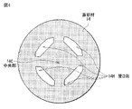
- It is a top view which shows the planar structure of a lid member.
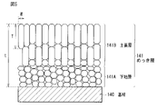
- It is a schematic cross-sectional view which shows the crystal structure of the plating layer which a lid member has.
- the secondary battery described here is a secondary battery that obtains a battery capacity by utilizing the occlusion and release of an electrode reactant, and includes a positive electrode, a negative electrode, and an electrolytic solution.
- the charge capacity of the negative electrode is larger than the discharge capacity of the positive electrode in order to prevent the electrode reactant from precipitating on the surface of the negative electrode during charging. That is, the electrochemical capacity per unit area of the negative electrode is larger than the electrochemical capacity per unit area of the positive electrode.
- the electrode reactant is not particularly limited, but is a light metal such as an alkali metal and an alkaline earth metal.
- Alkali metals include lithium, sodium and potassium.
- Alkaline earth metals include beryllium, magnesium and calcium.
- a secondary battery that obtains battery capacity by utilizing the occlusion and release of lithium is a so-called lithium ion secondary battery.
- lithium ion secondary battery lithium is occluded and released in an ionic state.
- FIG. 1 is a cross-sectional view showing a cross-sectional configuration of a secondary battery.
- FIG. 2 is an enlarged cross-sectional view showing a cross-sectional configuration of a main portion (winding electrode body 20) of the secondary battery shown in FIG. 1. However, FIG. 2 shows only a part of the wound electrode body 20.
- the secondary battery shown in FIG. 1 is a cylindrical lithium-ion secondary battery in which a wound electrode body 20, which is a battery element, is housed inside a cylindrical battery can 11.
- the secondary battery includes a pair of insulating plates 12 and 13 and a wound electrode body 20 inside the battery can 11.
- the wound electrode body 20 is an electrode body formed by winding a positive electrode 21 and a negative electrode 22 laminated to each other via a separator 23.
- the wound electrode body 20 is impregnated with an electrolytic solution which is a liquid electrolyte.
- the battery can 11 contains one or more of iron (Fe), aluminum (Al), alloys thereof, and the like, and has a hollow structure in which one end is closed and the other end is open. Is provided.
- the surface of the battery can 11 may be plated with nickel (Ni) or the like.
- Each of the insulating plates 12 and 13 extends in a direction intersecting the winding peripheral surface of the wound electrode body 20, and is arranged so as to face each other so as to sandwich the wound electrode body 20.
- a lid member 14, a safety valve mechanism 15, and a heat-sensitive resistance element (PTC element) 16 are crimped to the open end of the battery can 11 via a gasket 17.
- the gasket 17 contains an insulating material. Asphalt or the like may be applied to the surface of the gasket 17.
- the lid member 14 is made of stainless steel whose surface is nickel (Ni) plated. The details of the configuration of the lid member 14 will be described later.
- the safety valve mechanism 15 and the heat-sensitive resistance element 16 are provided inside the lid member 14.
- the safety valve mechanism 15 is electrically connected to the lid member 14 via the heat-sensitive resistance element 16.
- the safety valve mechanism 15 reverses the disk plate 15A when the internal pressure of the battery can 11 exceeds a certain level due to an internal short circuit, external heating, or the like, thereby causing electricity between the lid member 14 and the wound electrode body 20. Disconnect the target connection.
- the heat-sensitive resistance element 16 is an element whose resistance increases as the temperature rises.
- the heat-sensitive resistance element 16 is provided to prevent abnormal heat generation due to a large current.
- the center pin 24 is inserted into the space provided at the winding center of the winding electrode body 20. However, the center pin 24 may not be provided in some cases.
- a positive electrode lead 25 containing any one or more of conductive materials such as aluminum is connected to the positive electrode 21.
- the positive electrode lead 25 is electrically connected to the lid member 14 via the safety valve mechanism 15.
- a negative electrode lead 26 containing any one or more of conductive materials such as nickel is connected to the negative electrode 22.
- the negative electrode lead 26 is electrically connected to the battery can 11.
- the positive electrode 21 includes a positive electrode current collector 21A and two positive electrode active material layers 21B provided on both sides of the positive electrode current collector 21A.
- the positive electrode active material layer 21B may be provided only on one side of the positive electrode current collector 21A.
- the positive electrode current collector 21A contains any one or more of conductive materials such as aluminum, nickel, and stainless steel.
- the positive electrode current collector 21A may have a single-layer structure or a multi-layer structure.
- the positive electrode active material layer 21B contains one or more positive electrode active materials capable of occluding and releasing lithium.
- the positive electrode active material may be a lithium-containing composite oxide or a lithium-containing compound such as a lithium-containing phosphoric acid compound.
- the lithium-containing composite oxide is an oxide containing lithium and one or more other elements as constituent elements, and has a crystal structure of either a layered rock salt type or a spinel type. ..
- the lithium-containing phosphoric acid compound is a phosphoric acid compound containing lithium and one or more other elements as constituent elements, and is a compound having a crystal structure such as an olivine type.
- the above-mentioned other element is one kind or two or more kinds of arbitrary elements other than lithium.
- the other element is preferably an element belonging to groups 2 to 15 in the long periodic table, and more preferably any one of nickel (Ni), cobalt (Co), manganese (Mn), and iron (Fe). One or more.
- the battery element can generate a higher voltage.
- the positive electrode active material may be an oxide such as titanium oxide, vanadium oxide, or manganese dioxide, a disulfide such as titanium disulfide or molybdenum sulfide, and a chalcogen such as niobium selenium. It may be a compound or a conductive polymer such as sulfur, polyaniline, or polythiophene.
- the positive electrode active material layer 21B may further contain any one or more of the binder or the conductive material.
- the binder may be synthetic rubber such as styrene-butadiene rubber, fluorine-based rubber, or ethylenepropylene diene synthetic rubber, and one or more of polymer compounds such as polyvinylidene fluoride or polyimide. May be.
- the conductive material may contain one or more carbon materials such as graphite, carbon black, acetylene black, or Ketjen black, and may contain a metal material, a conductive polymer, or the like.
- the negative electrode 22 includes a negative electrode current collector 22A and a negative electrode active material layer 22B provided on both sides or one side of the negative electrode current collector 22A.
- the negative electrode current collector 22A contains any one or more of conductive materials such as copper, aluminum, nickel, and stainless steel.
- the negative electrode current collector 22A may have a single-layer structure or a multi-layer structure.
- the surface of the negative electrode current collector 22A may be roughened by using an electrolytic method or the like. In such a case, the negative electrode current collector 22A can improve the adhesion to the negative electrode active material layer 22B by utilizing the so-called anchor effect.
- the capacity of the negative electrode active material that can be charged is preferably larger than the discharge capacity of the positive electrode 21 in order to prevent unintentional precipitation of lithium metal on the surface of the negative electrode 22 during charging. That is, the electrochemical equivalent of the negative electrode active material is preferably larger than the electrochemical equivalent of the positive electrode 21.
- the negative electrode active material layer 22B contains one or more negative electrode active materials capable of occluding and releasing lithium.
- the negative electrode active material may be a carbon material, a metal-based material, or a mixture of a carbon material and a metal-based material.
- the carbon material is a material containing carbon as a constituent element, and is easily graphitizable carbon, non-graphitizable carbon, graphite, or the like.
- the carbon material is pyrolytic carbon, coke, glassy carbon fiber, calcined organic polymer compound, activated carbon, carbon black, low crystalline carbon, amorphous carbon, or the like.
- the shape of the carbon material is fibrous, spherical, granular, or scaly. Since the carbon material hardly changes the crystal structure at the time of occlusion of lithium and at the time of release of lithium, it is possible to stably obtain a high energy density. Further, since the carbon material also functions as a negative electrode conductive agent, the conductivity of the negative electrode active material layer 22B can be improved.
- the metallic material is a material containing one or more of metal elements or metalloid elements as constituent elements.
- the metal-based material may be a simple substance, an alloy, or a compound, or may be a mixture of two or more of these. Further, the metal-based material may include, in addition to the material composed of two or more kinds of metal elements, a material composed of one kind or two or more kinds of metal elements and one kind or two or more kinds of metalloid elements. Further, the metallic material may contain one kind or two or more kinds of non-metal elements as constituent elements.
- the structure of the metallic material is a solid solution, a eutectic (eutectic mixture), an intermetallic compound, or a coexistence of two or more of these.
- the metal element or metalloid element contained in the metal-based material is an element capable of forming an alloy with lithium.
- Metallic elements or metalloid elements contained in metallic materials include magnesium (Mg), boron (B), aluminum (Al), gallium (Ga), indium (In), silicon (Si), germanium (Ge), and tin. (Sn), lead (Pb), bismuth (Bi), cadmium (Cd), silver (Ag), zinc (Zn), hafnium (Hf), zirconium (Zr), ittrium (Y), palladium (Pd), or Platinum (Pt) and the like.
- the metal-based material silicon and tin are preferable, and silicon is more preferable. Since silicon and tin have an excellent lithium storage capacity and an excellent lithium release capacity, the negative electrode 22 can obtain a significantly high energy density.
- the metal-based material may be a simple substance of silicon, an alloy of silicon, a compound of silicon, a simple substance of tin, an alloy of tin, or a compound of tin, and these two types are used. The above mixture may be used, or a material containing one or more of these phases may be used.
- the negative electrode active material preferably contains both a carbon material and a metal-based material for the reasons described below.
- a metal-based material particularly a material containing silicon or tin as a constituent element, has a high theoretical capacity, but tends to expand and contract violently during charging and discharging.
- the carbon material has a low theoretical capacity, it does not easily expand and contract during charging and discharging. Therefore, the negative electrode active material can suppress the expansion and contraction of the negative electrode active material layer 22B during charging and discharging while obtaining a high theoretical capacity (that is, battery capacity) by using a carbon material and a metal-based material in combination. can.
- the negative electrode active material layer 22B may further contain any one or more of the binder or the conductive material.
- the binder may be synthetic rubber such as styrene-butadiene rubber, fluorine-based rubber, or ethylenepropylene diene synthetic rubber, and one or more of polymer compounds such as polyvinylidene fluoride or polyimide. May be.
- the conductive material may contain one or more carbon materials such as graphite, carbon black, acetylene black, or Ketjen black, and may contain a metal material, a conductive polymer, or the like.
- the separator 23 is a porous film that is interposed between the positive electrode 21 and the negative electrode 22 to allow lithium ions to pass through and prevent a short circuit due to contact between the positive electrode 21 and the negative electrode 22.
- the separator 23 may be made of a synthetic resin such as polytetrafluoroethylene, polypropylene, or polyethylene, or may be made of ceramic or the like.
- the separator 23 may be a single-layer film or a multilayer film in which two or more kinds of porous films are laminated.
- a polymer compound layer may be further provided on one side or both sides of the separator 23. Since the polymer compound layer can improve the adhesion of each of the positive electrode 21 and the negative electrode 22 to the separator 23, the wound electrode body 20 can be made less likely to be distorted. Since the wound electrode body 20 is less likely to be distorted, the decomposition reaction of the electrolytic solution is suppressed, and the leakage of the electrolytic solution impregnated in the base material layer is also suppressed. Therefore, the secondary battery is repeatedly charged and discharged. It is possible to suppress an increase in resistance and swelling at the time.
- the polymer compound layer may contain one or more of the polymer compounds (such as polyvinylidene fluoride) having high physical strength and chemical stability. Further, the polymer compound layer may contain one or more kinds of inorganic particles such as aluminum oxide or aluminum nitride in order to improve safety.
- the electrolytic solution contains a solvent and an electrolyte salt, and is impregnated into the wound electrode body 20 around which the positive electrode 21 and the negative electrode 22 are wound.
- the solvent includes one or more non-aqueous solvents such as organic solvents.
- the non-aqueous solvent contains one or more of carbonic acid esters, chain carboxylic acid esters, lactones, or nitrile compounds.
- Carbonated ester means both cyclic carbonate and chain carbonate.
- Cyclic carbonic acid ester is ethylene carbonate, propylene carbonate, butylene carbonate and the like.
- the chain carbonate ester is dimethyl carbonate, diethyl carbonate, ethylmethyl carbonate, methylpropyl carbonate and the like.
- the chain carboxylic acid ester is methyl acetate, ethyl acetate, methyl propionate, ethyl propionate, propyl propionate, methyl butyrate, methyl isobutyrate, methyl trimethyl acetate, ethyl trimethyl acetate and the like.
- the lactone is ⁇ -butyrolactone, ⁇ -valerolactone and the like.
- the nitrile compound is acetonitrile, methoxyacetonitrile, 3-methoxypropionitrile and the like.
- the solvent is 1,2-dimethoxyethane, tetrahydrofuran, 2-methyltetrahydrofuran, tetrahydropyran, 1,3-dioxolane, 4-methyl-1,3-dioxolane, 1,4-dioxane, N, N-dimethyl. It may further contain formamide, N-methylpyrrolidinone, N-methyloxazolidinone, N, N'-dimethylimidazolidinone, nitromethane, nitroethane, sulfolane, trimethyl phosphate, or dimethyl sulfoxide.
- the solvent may be any one of carbonic acid esters such as ethylene carbonate, propylene carbonate, dimethyl carbonate, diethyl carbonate and ethylmethyl carbonate. It is preferable to include two or more types.
- the solvent is a cyclic carbonate ester such as ethylene carbonate and propylene carbonate which is a high viscosity (high dielectric constant) solvent (specific dielectric constant ⁇ ⁇ 30), and a low viscosity solvent (viscosity ⁇ 1 mPa ⁇ s). It is more preferable to contain in combination with a chain carbonate ester such as dimethyl carbonate, ethylmethyl carbonate and diethyl carbonate. According to this, the solvent can improve the dissociative property of the electrolyte salt and the mobility of ions.
- a cyclic carbonate ester such as ethylene carbonate and propylene carbonate which is a high viscosity (high dielectric constant) solvent (specific dielectric constant ⁇ ⁇ 30), and a low viscosity solvent (viscosity ⁇ 1 mPa ⁇ s). It is more preferable to contain in combination with a chain carbonate ester such as dimethyl carbonate, ethylmethyl carbonate and die
- the solvent contains, as an additive, any one or more of unsaturated cyclic carbonate ester, halogenated carbonate ester, sulfonic acid ester, acid anhydride, dinitrile compound, diisocyanate compound, phosphoric acid ester and the like. But it may be. According to this, the solvent can improve the chemical stability of the electrolytic solution.
- Electrolyte salts include one or more salts such as lithium salts. However, the electrolyte salt may contain a salt other than the lithium salt such as a light metal salt.
- Lithium salts include lithium hexafluorophosphate (LiPF 6 ), lithium tetrafluoroborate (LiBF 4 ), lithium perchlorate (LiClO 4 ), lithium hexafluoride arsenide (LiAsF 6 ), and tetraphenylboric acid.
- the electrolyte salt preferably contains any one or more of lithium hexafluorophosphate, lithium tetrafluoroborate, lithium perchlorate and lithium hexafluoride, and it is preferable that the electrolyte salt contains six types. It is more preferable to contain lithium phosphate. In such a case, the electrolyte salt can reduce the internal resistance, so that the battery characteristics of the secondary battery can be further improved.
- the content of the electrolyte salt is not particularly limited, but in order to obtain high ionic conductivity, the content of the electrolyte salt is preferably 0.3 mol / kg to 3.0 mol / kg with respect to the solvent.
- the materials of the positive electrode, the negative electrode, the separator, and the electrolytic solution are not limited to the examples shown above, and other materials may be used.
- FIG. 3 is an enlarged cross-sectional view of the vicinity of the lid member 14 of FIG.
- FIG. 4 is a top view showing a planar configuration of the lid member 14.
- FIG. 5 is a schematic cross-sectional view showing the crystal structure of the plating layer 141 included in the lid member 14.
- the lid member 14 included in the secondary battery according to the present embodiment includes a base material 140 made of stainless steel and a plating layer 141 made of nickel plating.
- the base material 140 is a member that constitutes the shape of the lid member 14, and is provided in a circular planar shape.
- the base material 140 is provided with an opening 14H so as to surround the central portion 14C point-symmetrically, and the central portion 14C is provided so as to be convex on the opposite side to the battery can 11.
- the plating layer 141 covers the surface of the base material 140 and is provided on the entire surface including both main surfaces and end faces of the base material 140. Specifically, the plating layer 141 is provided on the entire surface including both main surfaces, end faces, and the inner end faces of the opening 14H having a circular planar shape of the base material 140.
- Such a plating layer 141 can be formed by forming an opening 14H or the like in the base material 140, shaping the base material 140, and then immersing the entire base material 140 in a plating solution in an electroplating tank. can.
- gas may be generated inside the battery if the battery burns due to an excessive charge / discharge reaction.
- the sealing of the battery can 11 on the lid member 14 side is broken, and the gas generated inside the battery is the opening 14H of the lid member 14. Is discharged through.
- the lid member 14 expands the area of the opening 14H, and the base material 140 is made of higher-strength stainless steel, so that the strength of the lid member 14 is maintained and the gas inside the battery is burned. Can be discharged more efficiently.
- the base material 140 of the lid member 14 is made of stainless steel, and as demonstrated in the examples described later, in a drop test (drop test according to JIS C 8712). You can get better grades. That is, the secondary battery in which the base material 140 is made of stainless steel can further suppress the leakage of the electrolytic solution at the time of dropping, so that the passing rate in the above-mentioned drop test can be further increased.
- the opening 14H is provided in an area of 9% or more and 12% or less with respect to the cross-sectional area of the internal space of the secondary battery formed by the battery can 11 and the lid member 14.
- the secondary battery can obtain better results in the combustion test (UL Standard 1642 projectile test) as demonstrated in Examples described later. That is, the secondary battery having the opening 14H having the area ratio in the above range can further increase the pass rate in the above combustion test.
- the gas discharge capacity from the opening 14H is more preferable.
- the area ratio of the opening 14H is 12% or less with respect to the cross-sectional area of the internal space of the secondary battery, the strength of the lid member 14 is such that the leakage of the electrolytic solution in the drop test can be remarkably suppressed. Is preferable because it can improve.
- the base material 140 made of stainless steel having a relatively high electric resistance value is entirely covered with a plating layer 141 made of nickel plating having a low electric resistance value. According to this, the lid member 14 can keep the electric resistance value between both main surfaces lower through the plating layer 141 formed on the end surface. Therefore, the lid member 14 can transmit the current taken out from the positive electrode 21 of the wound electrode body 20 to the outside of the secondary battery with low resistance.
- the plating layer 141 is formed so as to have a crystal structure containing 80% or more of columnar crystals.
- the columnar crystal is a crystal structure that grows vertically in the thickness direction of nickel plating, and is a crystal structure that tends to occur when nickel plating is formed with a small current value over a long period of time. Since the plating layer 141 containing a large number of columnar crystals has few crystal grain boundaries that trap impurities, it is difficult for the peel strength of the crystal grain boundaries to decrease due to heat and pressure during welding. Therefore, the plating layer 141 containing a large amount of columnar crystals can further increase the peel strength and the bonding strength by welding.
- nickel plating when nickel plating is formed with a large current in a short time, nickel plating is formed by containing more fine granular crystals than columnar crystals. Since the plating layer 141 containing a large amount of granular crystals has a large number of crystal grain boundaries trapped with impurities, the peel strength of the crystal grain boundaries is likely to decrease due to heat and pressure during welding. Therefore, in the plating layer 141 containing a large amount of granular crystals, the peel strength of the plating layer 141 tends to be low, and the bonding strength due to welding tends to be low.
- the peel strength of the plating layer 141 can be further increased, and the lid member can be further enhanced.
- the bonding strength with respect to 14 can be further increased.
- the plating layer 141 includes a base layer 141A formed on the base material 140 and a main layer 141B formed on the base layer 141A.
- the base layer 141A is a layer formed on the surface of a base material 140 made of stainless steel and mainly containing granular crystals.
- the base layer 141A is formed as a thin film after removing the oxide film on the surface of the base material 140 made of stainless steel.
- the main layer 141B is a layer formed on the base layer 141A and mainly containing columnar crystals.
- the main layer 141B is a layer that occupies most of the plating layer 141, and is formed on the base layer 141A to be thicker than the base layer 141A.
- the boundary between the base layer 141A and the main layer 141B may be the thickness at which columnar crystals begin to form. That is, the base layer 141A may represent a layer of the plating layer 141 formed only of granular crystals, and the main layer 141B represents a layer of the plating layer 141 formed by including columnar crystals. You may.
- the plating layer 141 is provided with the base layer 141A having a thickness of 0.2 ⁇ m or more and 0.8 ⁇ m or less, and the main layer 141B having a thickness of 2.1 ⁇ m or more and 4.0 ⁇ m or less.
- the balance between the base layer 141A mainly containing granular crystals and the main layer 141B mainly containing columnar crystals is suitable, so that the peel strength of the plating layer 141 is increased and the lid member 14 is increased. It is possible to further increase the joint strength of the weld to the metal.
- the peel strength between the base layer 141A and the main layer 141B becomes excessively low, which is not preferable.
- the thickness of the base layer 141A is more than 0.8 ⁇ m, the peel strength between the base layer 141A and the main layer 141B is excessively strong, and it becomes difficult to melt and weld the plating layer 141 to other members, which is not preferable.
- the thickness of the main layer 141B is less than 2.1 ⁇ m, the main layer 141B is excessively soft and the peel strength is excessively low, which is not preferable.
- the thickness of the main layer 141B exceeds 4.0 ⁇ m, the main layer 141B is excessively hard, which makes it difficult to melt and weld the plating layer 141 to other members, which is not preferable.
- the columnar crystals in the crystal structure of the plating layer 141 have a crystal height T of 1/3 t in the thickness direction of the plating layer 141, where t is the total thickness of the plating layer 141.
- the crystal having the above and the crystal width W in the in-plane direction of the plating layer 141 may be 1/10 t or more.
- the granular crystal may represent a crystal that does not satisfy the above-mentioned columnar crystal conditions.
- the plating layer 141 is provided so that the proportion of columnar crystals in the entire cross section of the plating layer 141 including the base layer 141A and the main layer 141B is 80% or more.
- the secondary battery according to this embodiment can perform charge / discharge operation as follows.
- lithium ions are released from the positive electrode 21 and lithium ions are occluded in the negative electrode 22 via the electrolytic solution.
- lithium ions are released from the negative electrode 22 and lithium ions are occluded in the positive electrode 21 via the electrolytic solution. That is, in the secondary battery, lithium ions can be charged and discharged by moving between the positive electrode 21 and the negative electrode 22 via the electrolytic solution.
- the secondary battery according to this embodiment can be manufactured by the procedure described below. Specifically, after the positive electrode 21 and the negative electrode 22 are manufactured, the lithium ion secondary battery is assembled.
- a positive electrode mixture is prepared by mixing a positive electrode active material with a positive electrode binder, a positive electrode conductive agent, and the like, if necessary.
- a paste-like positive electrode mixture slurry is prepared by dispersing or dissolving the positive electrode mixture in an organic solvent or the like.
- the positive electrode mixture slurry is applied to both surfaces of the positive electrode current collector 21A, and then the positive electrode mixture slurry is dried to form the positive electrode active material layer 21B.
- the positive electrode active material layer 21B may be compression-molded using a roll press machine or the like. In such a case, the positive electrode active material layer 21B may be heated or may be compression-molded by repeating it a plurality of times.
- the negative electrode 22 can be manufactured by the same procedure as the procedure for manufacturing the positive electrode 21 described above.
- a negative electrode mixture is prepared by mixing a negative electrode active material with a negative electrode binder, a negative electrode conductive agent, and the like, if necessary.
- a paste-like negative electrode mixture slurry is prepared by dispersing or dissolving the negative electrode mixture in an organic solvent or the like.
- the negative electrode mixture slurry is applied to both sides of the negative electrode current collector 22A, and then the negative electrode mixture slurry is dried to form the negative electrode active material layer 22B.
- the negative electrode active material layer 22B may be compression molded.
- the positive electrode lead 25 is connected to the positive electrode current collector 21A by using a welding method or the like, and the negative electrode lead 26 is connected to the negative electrode current collector 22A by using a welding method or the like.
- the positive electrode 21 and the negative electrode 22 are laminated with each other via the separator 23, and then the positive electrode 21, the negative electrode 22 and the separator 23 are wound to form a wound body.
- the center pin 24 is inserted into the space provided at the winding center of the winding body.
- the winding body is housed inside the battery can 11 together with the insulating plates 12 and 13 so that the winding body is sandwiched between the pair of insulating plates 12 and 13.
- the positive electrode lead 25 is connected to the safety valve mechanism 15 by using a welding method or the like
- the negative electrode lead 26 is connected to the battery can 11 by using a welding method or the like.
- the winding body is impregnated with the electrolytic solution by injecting the electrolytic solution into the inside of the battery can 11.
- each of the positive electrode 21, the negative electrode 22, and the separator 23 is impregnated with the electrolytic solution, and the wound electrode body 20 is formed.
- the open end of the battery can 11 is crimped via the gasket 17, and the lid member 14, the safety valve mechanism 15, and the heat-sensitive resistance element 16 are attached to the open end of the battery can 11.
- the wound electrode body 20 is enclosed inside the battery can 11, and the secondary battery is completed.
- the lid member 14 is made of stainless steel (base material 140) plated with nickel (plating layer 141) containing columnar crystals at a ratio of 80% or more in the crystal structure. .. According to this, the secondary battery can further increase the peel strength of the plating layer 141 and further increase the bonding strength of welding to the lid member 14. Further, in the secondary battery, the base material 140 of the lid member 14 is made of high-strength stainless steel, so that the leakage of the electrolytic solution at the time of dropping can be further suppressed. Therefore, the secondary battery according to the present embodiment can improve the reliability.
- the plating layer 141 is provided so as to include a base layer 141A having a thickness of 0.2 ⁇ m or more and 0.8 ⁇ m or less, and a main layer 141B having a thickness of 2.1 ⁇ m or more and 4.0 ⁇ m or less. Is preferable.
- the secondary battery can increase the peel strength of the plating layer 141 and further increase the welding strength of the weld to the lid member 14, so that the reliability can be improved.
- the area ratio of the opening 14H provided in the lid member 14 is 9% or more 12 with respect to the cross-sectional area of the internal space of the secondary battery formed by the battery can 11 and the lid member 14. % Or less is preferable.
- the secondary battery can achieve both the gas discharge capacity from the opening 14H and the strength of the lid member 14, so that the reliability can be further improved.
- a nickel-plated plating layer 141 may be provided on the entire surface including the end face of the base material 140. In such a case, since the secondary battery can further enhance the electrical conductivity between both main surfaces of the lid member 14, it is possible to take out the current from the battery element with a lower resistance.
- the separator 23 has been described as being a porous membrane.
- the separator 23 may be a laminated film including a polymer compound layer.
- the separator 23 may be configured to include the base material layer which is the above-mentioned porous film and the polymer compound layer provided on one side or both sides of the base material layer.
- the polymer compound layer contains a polymer compound such as polyvinylidene fluoride, which has excellent physical strength and is electrochemically stable. According to this, since the separator 23 can improve the adhesion to each of the positive electrode 21 and the negative electrode 22, it is possible to suppress the positional deviation inside the wound electrode body 20. Therefore, the secondary battery can suppress the occurrence of swelling even when the decomposition reaction of the electrolytic solution occurs.
- the substrate layer and the polymer compound layer of the separator 23 may contain a plurality of particles.
- the plurality of types of particles may be any one or more than one of particles such as inorganic particles and resin particles. According to this, since the secondary battery can dissipate heat with a plurality of particles when it generates heat, heat resistance and safety can be improved.
- the inorganic particles are not particularly limited, and may be particles such as aluminum oxide (alumina), aluminum nitride, boehmite, silicon oxide (silica), titanium oxide (titania), magnesium oxide (magnesia), and zirconium oxide (zirconia). good.
- the separator 23 of the laminated film containing the polymer compound layer can be produced by preparing a precursor solution containing the polymer compound, an organic solvent, etc., and then applying the precursor solution to one or both sides of the base material layer. can.
- lithium can move between the positive electrode 21 and the negative electrode 22, so that the secondary battery can obtain the same effect.
- the element structure of the wound electrode body 20 has been described as being a laminated type in which a sheet-shaped positive electrode 21, a negative electrode 22, and a separator 23 are laminated.
- the element structure of the wound electrode body 20 is not limited to the above embodiment.
- the element structure of the wound electrode body 20 may be a ninety-nine-fold type element structure in which the positive electrode 21, the negative electrode 22 and the separator 23 are folded in a zigzag manner, and may be a stack-and-fold type element structure. It may be.
- the application (application example) of the secondary battery is not particularly limited.
- the secondary battery used as a power source may be used as a main power source for electronic devices and electric vehicles, or may be used as an auxiliary power source.
- the main power source is a power source that is preferentially used regardless of the presence or absence of another power source
- the auxiliary power source is a power source that is used in place of the main power source or a power source that can be switched from the main power source.
- secondary batteries include video cameras, digital still cameras, mobile phones, laptop computers, headphone stereos, electronic devices such as portable radios and portable information terminals, and storage devices such as backup power supplies and memory cards.
- Electric tools such as electric drills and saws, battery packs mounted on electronic devices, medical electronic devices such as pacemakers and hearing aids, electric vehicles such as electric vehicles (including hybrid vehicles), and in emergencies.
- a power storage system such as a household or industrial battery system that stores power in preparation.
- one secondary battery may be used, or a plurality of secondary batteries may be used.
- the battery pack may be configured by using a single battery or may be configured by using an assembled battery.
- the electric vehicle is a vehicle that operates (runs) using a secondary battery as a drive power source, and may be a hybrid vehicle that also includes a drive source other than the secondary battery.
- the household electric power storage system can operate household electric products and the like by using the electric power stored in the secondary battery which is the electric power storage source.
- FIG. 6 shows the block configuration of the battery pack.
- the battery pack described here is a battery pack (so-called soft pack) using one secondary battery, and is mounted on an electronic device represented by a smartphone.
- the battery pack includes a power supply 111 and a circuit board 116.
- the circuit board 116 is connected to the power supply 111 and includes a positive electrode terminal 125, a negative electrode terminal 127, and a temperature detection terminal 126.
- the power supply 111 includes one secondary battery.
- the positive electrode is connected to the positive electrode terminal 125 and the negative electrode is connected to the negative electrode terminal 127.
- the power supply 111 can be connected to the outside via the positive electrode terminal 125 and the negative electrode terminal 127, and can be charged and discharged via the positive electrode terminal 125 and the negative electrode terminal 127.
- the circuit board 116 includes a control unit 121, a switch unit 122, a PTC element 123, and a temperature detection unit 124. However, the PTC element 123 may be omitted.
- the control unit 121 includes a central processing unit (CPU: Central Processing Unit), a memory, and the like, and controls the operation of the entire battery pack.
- the control unit 121 detects and controls the usage state of the power supply 111 as needed.
- the control unit 121 disconnects the switch unit 122 so that the charging current flows in the current path of the power supply 111. Can be avoided.
- the overcharge detection voltage and the overdischarge detection voltage are not particularly limited. As an example, the overcharge detection voltage is 4.2V ⁇ 0.05V, and the overdischarge detection voltage is 2.4V ⁇ 0.1V.
- the switch unit 122 includes a charge control switch, a discharge control switch, a charging diode, a discharging diode, and the like, and switches whether or not the power supply 111 is connected to an external device according to the instruction of the control unit 121.
- the switch unit 122 includes a field effect transistor (MOSFET: Metal-Oxide-Semiconductor Dutor Field-Effective Transistor) using a metal-oxide-semiconductor. The charge / discharge current is detected based on the ON resistance of the switch unit 122.
- MOSFET Metal-Oxide-Semiconductor Dutor Field-Effective Transistor
- the temperature detection unit 124 includes a temperature detection element such as a thermistor, measures the temperature of the power supply 111 using the temperature detection terminal 126, and outputs the temperature measurement result to the control unit 121.
- the temperature measurement result measured by the temperature detection unit 124 is that the control unit 121 performs charge / discharge control of the power supply 111 when abnormal heat generation occurs, and the control unit 121 corrects the remaining capacity of the power supply 111 when calculating the remaining capacity. It is used when doing so.
- a positive electrode active material, a positive electrode binder, and a positive electrode conductive agent were mixed to form a positive electrode mixture, and then the positive electrode mixture was added to an organic solvent to prepare a paste-like positive electrode mixture slurry.
- the prepared positive electrode mixture slurry was applied to both sides of the positive electrode current collector (aluminum foil) and dried by heating to form a positive electrode active material layer.
- a positive electrode was produced by compression molding the positive electrode active material layer using a roll press machine.
- a negative electrode mixture was prepared by mixing a negative electrode active material, a negative electrode binder, and a negative electrode conductive agent, and then the negative electrode mixture was added to an organic solvent to prepare a paste-like negative electrode mixture slurry.
- the prepared negative electrode mixture slurry was applied to both sides of the negative electrode current collector (copper foil) and dried by heating to form a negative electrode active material layer. Then, the negative electrode was produced by compression molding the negative electrode active material layer using a roll press machine.
- an electrolyte salt was added to the solvent, and the electrolyte salt was dissolved in the solvent to prepare an electrolytic solution.
- the positive electrode lead was connected to the positive electrode by using a welding method or the like, and the negative electrode lead was connected to the negative electrode by similarly using a welding method or the like.
- a positive electrode and a negative electrode were laminated and wound on each other via a separator to form a wound body, and the formed wound body was housed inside a cylindrical battery can having an outer diameter of 26 mm.
- the positive electrode lead is connected to the safety valve mechanism by using a welding method or the like, and the negative electrode lead is connected to the battery can by using a welding method or the like, and the electrolytic solution is injected into the battery can to supply the electrolytic solution.
- the winder was impregnated.
- the open end of the battery can is sealed with a lid member made of nickel-plated stainless steel via a gasket, and the winding body is enclosed inside the battery can to form a secondary battery.
- the proportion of columnar crystals in the plating layer is determined by exposing the cross section of the plating layer using a focused ion beam (FIB) device and then scanning the exposed cross section of the plating layer with a scanning ion microscope (FIB). : SIM) was calculated by observing at a magnification of 30,000 times.
- FIB focused ion beam
- SIM scanning ion microscope
- the area ratio of columnar crystals in the cross section of the plating layer having a width of 3 tons in the in-plane direction of the plating layer was calculated.
- the columnar crystals have a crystal height of 1/3 t or more in the thickness direction of the plating layer and a crystal width of 1/10 t or more in the in-plane direction of the plating layer with respect to the total thickness t of the plating layer. It was made into crystals.
- the drop test was performed according to JIS C 8712 with the number of tests set to 30. Specifically, after dropping the secondary battery three times from a height of 10 m with the lid member side down on the concrete floor, the presence or absence of leakage of the electrolytic solution from the secondary battery was evaluated. In this test, the case where the electrolyte leaks from the secondary battery does not occur after the fall is judged as "A”, and the case where the electrolyte leaks from the secondary battery even a small amount after the fall is judged as "B”. I decided. "A” is better than "B".
- the combustion test was performed according to the UL Standard 1642 projectile test with the number of tests set to 10. In this test, when 90% or more of the number of tests passed, it was judged as "A”, and when 10% or more of the number of tests failed, it was judged as "B". "A" is better than "B”.
- the electric resistance of the lid member of the secondary battery according to the embodiment manufactured above was measured by the four-terminal method. Specifically, between the one main surface of the lid member facing the inside of the secondary battery (the area outside the opening) and the other main surface of the lid member facing the outside of the secondary battery (the area of the center). The electrical resistance of the above was measured by the four-terminal method, and the arithmetic mean value of 10 samples was calculated.
- the electric resistance value of the lid member whose entire surface including the end face is nickel-plated is 1.55 m ⁇
- the electric resistance value of the lid member whose entire main surface excluding the end face is nickel-plated is It was 1.74 m ⁇ . Therefore, in the lid member whose entire surface including the end face is nickel-plated, current flows through the plating layer covering the surface of the base material made of stainless steel, so that nickel plating is continuously performed between both main surfaces. It can be seen that the electric resistance value can be reduced for the lid member that has not been plated.
- the secondary batteries according to Examples 1 to 8 have a proportion of columnar crystals in the plating layer of 80% or more, a welding test is performed on the secondary batteries according to Comparative Examples 1 and 2. It can be seen that the result of is good. Further, since the secondary batteries according to Examples 1 to 5 include the thicknesses of the base layer and the main layer in the plating layer within the above-mentioned preferable ranges, the secondary batteries according to Examples 6 to 8 are compared with the secondary batteries according to Examples 6 to 8. , It can be seen that the results of the welding test are even better.
- the secondary batteries according to Examples 10 to 13 have a drop test with respect to Example 14 because the ratio of the total area of the openings to the cross-sectional area of the secondary batteries is 9% or more. It can be seen that the result of is good. Further, in the secondary batteries according to Examples 11 to 14, the ratio of the total area of the openings to the cross-sectional area of the secondary batteries is 12% or less, so that the result of the combustion test is better than that of Example 10. It turns out that it will be. That is, from the results shown in Table 2, it can be seen that the ratio of the total area of the openings to the cross-sectional area of the secondary battery is preferably 9% or more and 12% or less.
- the electrode reactant is lithium
- the electrode reactant is not particularly limited.
- the electrode reactant may be another alkali metal such as sodium and potassium, or an alkaline earth metal such as beryllium, magnesium and calcium.
- the electrode reactant may be another light metal such as aluminum.
Landscapes
- Chemical & Material Sciences (AREA)
- Chemical Kinetics & Catalysis (AREA)
- Electrochemistry (AREA)
- General Chemical & Material Sciences (AREA)
- Engineering & Computer Science (AREA)
- Inorganic Chemistry (AREA)
- Manufacturing & Machinery (AREA)
- Materials Engineering (AREA)
- Secondary Cells (AREA)
Priority Applications (3)
| Application Number | Priority Date | Filing Date | Title |
|---|---|---|---|
| CN202180068769.5A CN116325265A (zh) | 2020-10-15 | 2021-09-10 | 二次电池 |
| JP2022557276A JP7613476B2 (ja) | 2020-10-15 | 2021-09-10 | 二次電池 |
| US18/124,881 US20230223624A1 (en) | 2020-10-15 | 2023-03-22 | Secondary battery |
Applications Claiming Priority (2)
| Application Number | Priority Date | Filing Date | Title |
|---|---|---|---|
| JP2020-173645 | 2020-10-15 | ||
| JP2020173645 | 2020-10-15 |
Related Child Applications (1)
| Application Number | Title | Priority Date | Filing Date |
|---|---|---|---|
| US18/124,881 Continuation US20230223624A1 (en) | 2020-10-15 | 2023-03-22 | Secondary battery |
Publications (1)
| Publication Number | Publication Date |
|---|---|
| WO2022080050A1 true WO2022080050A1 (ja) | 2022-04-21 |
Family
ID=81208313
Family Applications (1)
| Application Number | Title | Priority Date | Filing Date |
|---|---|---|---|
| PCT/JP2021/033278 Ceased WO2022080050A1 (ja) | 2020-10-15 | 2021-09-10 | 二次電池 |
Country Status (4)
| Country | Link |
|---|---|
| US (1) | US20230223624A1 (https=) |
| JP (1) | JP7613476B2 (https=) |
| CN (1) | CN116325265A (https=) |
| WO (1) | WO2022080050A1 (https=) |
Cited By (1)
| Publication number | Priority date | Publication date | Assignee | Title |
|---|---|---|---|---|
| JP2025536218A (ja) * | 2023-08-01 | 2025-11-05 | エルジー エナジー ソリューション リミテッド | 二次電池用キャップアセンブリ、二次電池、バッテリーパック、および移動手段 |
Citations (3)
| Publication number | Priority date | Publication date | Assignee | Title |
|---|---|---|---|---|
| JPS58144759U (ja) * | 1982-03-25 | 1983-09-29 | 松下電器産業株式会社 | 密閉形アルカリ電池 |
| JP2003323869A (ja) * | 2002-04-30 | 2003-11-14 | Matsushita Electric Ind Co Ltd | 電池および電池モジュール |
| JP2019181710A (ja) * | 2018-04-03 | 2019-10-24 | 株式会社豊田中央研究所 | 金属樹脂接合体 |
Family Cites Families (2)
| Publication number | Priority date | Publication date | Assignee | Title |
|---|---|---|---|---|
| EP3269847A4 (en) * | 2015-03-13 | 2018-11-07 | Toyo Kohan Co., Ltd. | Method for producing surface-treated steel sheet for battery containers, and surface-treated steel sheet for battery containers |
| US11316223B2 (en) * | 2017-07-31 | 2022-04-26 | Panasonic Intellectual Property Management Co., Ltd. | Cylindrical battery |
-
2021
- 2021-09-10 WO PCT/JP2021/033278 patent/WO2022080050A1/ja not_active Ceased
- 2021-09-10 CN CN202180068769.5A patent/CN116325265A/zh active Pending
- 2021-09-10 JP JP2022557276A patent/JP7613476B2/ja active Active
-
2023
- 2023-03-22 US US18/124,881 patent/US20230223624A1/en active Pending
Patent Citations (3)
| Publication number | Priority date | Publication date | Assignee | Title |
|---|---|---|---|---|
| JPS58144759U (ja) * | 1982-03-25 | 1983-09-29 | 松下電器産業株式会社 | 密閉形アルカリ電池 |
| JP2003323869A (ja) * | 2002-04-30 | 2003-11-14 | Matsushita Electric Ind Co Ltd | 電池および電池モジュール |
| JP2019181710A (ja) * | 2018-04-03 | 2019-10-24 | 株式会社豊田中央研究所 | 金属樹脂接合体 |
Cited By (1)
| Publication number | Priority date | Publication date | Assignee | Title |
|---|---|---|---|---|
| JP2025536218A (ja) * | 2023-08-01 | 2025-11-05 | エルジー エナジー ソリューション リミテッド | 二次電池用キャップアセンブリ、二次電池、バッテリーパック、および移動手段 |
Also Published As
| Publication number | Publication date |
|---|---|
| JPWO2022080050A1 (https=) | 2022-04-21 |
| JP7613476B2 (ja) | 2025-01-15 |
| CN116325265A (zh) | 2023-06-23 |
| US20230223624A1 (en) | 2023-07-13 |
Similar Documents
| Publication | Publication Date | Title |
|---|---|---|
| US11489148B2 (en) | Secondary battery | |
| CN102780026B (zh) | 锂离子二次电池活性物质、二次电池电极、以及二次电池 | |
| CN102163710B (zh) | 用于锂离子二次电池的负极、锂离子二次电池、电动工具、电动车辆、和电力存储系统 | |
| JP5264099B2 (ja) | 非水電解質二次電池 | |
| KR101946732B1 (ko) | 비수전해질 전지 및 배터리 시스템 | |
| CN102148357B (zh) | 用于锂离子二次电池的负极、锂离子二次电池、电力工具、电动车辆、和电力存储系统 | |
| CN104956514B (zh) | 蓄电池系统 | |
| US20160118644A1 (en) | Lithium-ion storage battery and fabricating method thereof | |
| JP6362440B2 (ja) | 二次電池 | |
| CN107836061B (zh) | 非水电解质电池及电池包 | |
| JP4539658B2 (ja) | 電池 | |
| KR101936074B1 (ko) | 전해액 내장 부재를 포함하는 전지셀 | |
| JP2005293960A (ja) | リチウムイオン二次電池用負極およびリチウムイオン二次電池 | |
| JP2003100278A (ja) | 非水電解質二次電池 | |
| WO2020110799A1 (ja) | 二次電池 | |
| KR20040087936A (ko) | 전해액 및 이를 이용한 전지 | |
| US20230223624A1 (en) | Secondary battery | |
| WO2021145059A1 (ja) | 二次電池 | |
| WO2024204452A1 (ja) | 二次電池用正極および二次電池 | |
| JP2008140683A (ja) | 電池 | |
| CN119790511A (zh) | 二次电池用负极以及二次电池 | |
| WO2022070565A1 (ja) | 二次電池 | |
| WO2021065333A1 (ja) | 二次電池用負極および二次電池 | |
| US20230207792A1 (en) | Negative electrode for secondary battery, and secondary battery | |
| US20250112324A1 (en) | Battery and battery pack |
Legal Events
| Date | Code | Title | Description |
|---|---|---|---|
| 121 | Ep: the epo has been informed by wipo that ep was designated in this application |
Ref document number: 21879792 Country of ref document: EP Kind code of ref document: A1 |
|
| ENP | Entry into the national phase |
Ref document number: 2022557276 Country of ref document: JP Kind code of ref document: A |
|
| NENP | Non-entry into the national phase |
Ref country code: DE |
|
| 122 | Ep: pct application non-entry in european phase |
Ref document number: 21879792 Country of ref document: EP Kind code of ref document: A1 |