WO2022075151A1 - レーダー装置及びレーダーシステム - Google Patents
レーダー装置及びレーダーシステム Download PDFInfo
- Publication number
- WO2022075151A1 WO2022075151A1 PCT/JP2021/035879 JP2021035879W WO2022075151A1 WO 2022075151 A1 WO2022075151 A1 WO 2022075151A1 JP 2021035879 W JP2021035879 W JP 2021035879W WO 2022075151 A1 WO2022075151 A1 WO 2022075151A1
- Authority
- WO
- WIPO (PCT)
- Prior art keywords
- mode
- radar device
- signal
- processor
- wave
- Prior art date
- Legal status (The legal status is an assumption and is not a legal conclusion. Google has not performed a legal analysis and makes no representation as to the accuracy of the status listed.)
- Ceased
Links
Images





Classifications
-
- G—PHYSICS
- G01—MEASURING; TESTING
- G01S—RADIO DIRECTION-FINDING; RADIO NAVIGATION; DETERMINING DISTANCE OR VELOCITY BY USE OF RADIO WAVES; LOCATING OR PRESENCE-DETECTING BY USE OF THE REFLECTION OR RERADIATION OF RADIO WAVES; ANALOGOUS ARRANGEMENTS USING OTHER WAVES
- G01S13/00—Systems using the reflection or reradiation of radio waves, e.g. radar systems; Analogous systems using reflection or reradiation of waves whose nature or wavelength is irrelevant or unspecified
- G01S13/02—Systems using reflection of radio waves, e.g. primary radar systems; Analogous systems
- G01S13/06—Systems determining position data of a target
- G01S13/08—Systems for measuring distance only
- G01S13/32—Systems for measuring distance only using transmission of continuous waves, whether amplitude-, frequency-, or phase-modulated, or unmodulated
- G01S13/34—Systems for measuring distance only using transmission of continuous waves, whether amplitude-, frequency-, or phase-modulated, or unmodulated using transmission of continuous, frequency-modulated waves while heterodyning the received signal, or a signal derived therefrom, with a locally-generated signal related to the contemporaneously transmitted signal
-
- G—PHYSICS
- G01—MEASURING; TESTING
- G01S—RADIO DIRECTION-FINDING; RADIO NAVIGATION; DETERMINING DISTANCE OR VELOCITY BY USE OF RADIO WAVES; LOCATING OR PRESENCE-DETECTING BY USE OF THE REFLECTION OR RERADIATION OF RADIO WAVES; ANALOGOUS ARRANGEMENTS USING OTHER WAVES
- G01S13/00—Systems using the reflection or reradiation of radio waves, e.g. radar systems; Analogous systems using reflection or reradiation of waves whose nature or wavelength is irrelevant or unspecified
- G01S13/86—Combinations of radar systems with non-radar systems, e.g. sonar, direction finder
-
- G—PHYSICS
- G01—MEASURING; TESTING
- G01S—RADIO DIRECTION-FINDING; RADIO NAVIGATION; DETERMINING DISTANCE OR VELOCITY BY USE OF RADIO WAVES; LOCATING OR PRESENCE-DETECTING BY USE OF THE REFLECTION OR RERADIATION OF RADIO WAVES; ANALOGOUS ARRANGEMENTS USING OTHER WAVES
- G01S13/00—Systems using the reflection or reradiation of radio waves, e.g. radar systems; Analogous systems using reflection or reradiation of waves whose nature or wavelength is irrelevant or unspecified
- G01S13/88—Radar or analogous systems specially adapted for specific applications
- G01S13/93—Radar or analogous systems specially adapted for specific applications for anti-collision purposes
- G01S13/931—Radar or analogous systems specially adapted for specific applications for anti-collision purposes of land vehicles
-
- G—PHYSICS
- G01—MEASURING; TESTING
- G01S—RADIO DIRECTION-FINDING; RADIO NAVIGATION; DETERMINING DISTANCE OR VELOCITY BY USE OF RADIO WAVES; LOCATING OR PRESENCE-DETECTING BY USE OF THE REFLECTION OR RERADIATION OF RADIO WAVES; ANALOGOUS ARRANGEMENTS USING OTHER WAVES
- G01S7/00—Details of systems according to groups G01S13/00, G01S15/00, G01S17/00
- G01S7/02—Details of systems according to groups G01S13/00, G01S15/00, G01S17/00 of systems according to group G01S13/00
- G01S7/03—Details of HF subsystems specially adapted therefor, e.g. common to transmitter and receiver
-
- G—PHYSICS
- G08—SIGNALLING
- G08G—TRAFFIC CONTROL SYSTEMS
- G08G1/00—Traffic control systems for road vehicles
- G08G1/01—Detecting movement of traffic to be counted or controlled
- G08G1/04—Detecting movement of traffic to be counted or controlled using optical or ultrasonic detectors
Definitions
- This disclosure relates to radar devices and radar systems.
- Radar is an indispensable technology for warnings to ensure safety while driving a car and application to autonomous driving technology, for example.
- the output mode of the beat signal is a single mode.
- the calculation amount and the data transfer amount become large. Therefore, the load of signal processing of the signal received by the radar becomes large, and high-speed processing is required. There is a problem that enormous cost is required to deal with these.
- a radar device that satisfies the performance required under various conditions is provided.
- the radar apparatus comprises a transmitter, a receiver, a transmit wave, and the transmitted wave, which receives a reflected wave in an object of the transmitted wave, which transmits a transmitted wave whose frequency changes continuously. 2.
- the mode of mixing the transmitted wave and the reflected wave in the same phase and different phases is switched.
- the processor mixes the transmitted wave and the reflected wave in the same phase in one of the mixers for analog-digital conversion, and the transmitted wave and the reflected in two of the mixers.
- the second mode in which the waves are mixed in the same phase and antialiased for analog-digital conversion, and the transmitted wave and the reflected wave are mixed in different phases and antialiased for analog-digital conversion, and 2
- the transmitted wave and the reflected wave are mixed in the same phase for analog-digital conversion, and the transmitted wave and the reflected wave are mixed in different phases for analog-digital conversion. You may switch between the third mode and the mode.
- the processor may switch between the first mode, the second mode, and the third mode based on its own speed.
- the processor may select the first mode when its own speed is faster than a predetermined speed.
- the processor may switch between the first mode, the second mode, and the third mode based on the number of the objects that have received the reflected wave.
- the processor may select the third mode when the number of the objects is larger than the predetermined number.
- the different phase may be 90 degrees different from the same phase.
- the radar system includes the radar device according to any one of the above, a camera that acquires image information about the surrounding environment, target information including position information of the object output from the radar device, and output from the camera. It is provided with a recognizer that recognizes the object based on the image information to be obtained and calculates recognition information to which the position information of the object is added.
- the mode may be switched based on its own speed based on the image information.
- the mode may be switched based on the number of the objects in the recognition information.
- a block diagram schematically showing a configuration of a radar device according to an embodiment.
- the FMCW radar is a radar that uses a continuous wave whose wavelength changes continuously and obtains the distance, direction, and relative velocity from the beat signal (frequency difference between the transmitted wave and the reflected wave).
- This radar may be mounted, for example, toward the front of a moving body such as an automobile.
- the present invention is not limited to this, and may be fixed to the space.
- a moving body, particularly an automobile will be described, but the embodiment is appropriately used for other than the automobile. Is possible.
- FIG. 1 is a block diagram schematically showing a radar module that is a part of the radar device according to the embodiment.
- the radar device 1 includes a transmitter 10, a receiver 11, an oscillator 12, a plurality of mixers 13, a phase modulator 14, a plurality of antialiasing filters (hereinafter referred to as AAF) 15, and an analog-. It includes a digital converter (hereinafter referred to as ADC) 16 and a processor 17.
- ADC digital converter
- This radar device 1 is a device that measures the distance, direction, and relative velocity to an object using the above-mentioned FMCW radar.
- the portion surrounded by the broken line is a so-called front end, and may be formed by, for example, one IC chip.
- the transmitter 10 includes, for example, a power amplifier and a transmitting antenna.
- the transmitter 10 converts the signal output by the oscillator 12 to an appropriate intensity by, for example, a power amplifier, and transmits the signal to the outside via the transmitting antenna.
- the receiver 11 includes, for example, a receiving antenna and a low noise amplifier.
- the receiver 11 receives the signal output by the oscillator 12 reflected by the object, for example, by the receiving antenna, amplifies it to an appropriate intensity by a low noise amplifier, and outputs it.
- the oscillator 12 is, for example, a local oscillator.
- the oscillator 12 oscillates, for example, a signal (chirp signal) whose frequency increases monotonically with respect to time as a transmission wave.
- This chirp signal is a signal in which the frequency linearly increases from the first predetermined frequency to the second predetermined frequency higher than the first predetermined frequency in a predetermined time.
- the chirp signal returns to the first frequency and is repeated.
- the oscillator 12 outputs this chirp signal to the power amplifier of the transmitter 10, and the amplified signal is transmitted to a space, for example, a space in front of the moving object via the transmitting antenna. Further, the oscillator 12 sends a signal to the transmitter 10 and also outputs this chirp signal to a plurality of mixers 13.
- the mixer 13 is a so-called mixer (multiplexer), and a plurality of mixers 13 are provided in the radar device 1.
- the first mixer 13A which is one of them, mixes and outputs the signal output from the oscillator 12 and the signal received by the receiver 11.
- Another second mixer 13B mixes and outputs the signal output from the oscillator 12 whose phase is modulated by the phase modulator 14 and the signal received by the receiver 11.
- the phase modulator 14 modulates the phase of the input signal and outputs it. For example, the phase modulator 14 shifts the phase of the chirp signal output from the oscillator 12 by 90 degrees and outputs the chirp signal to the second mixer 13B.
- the oscillator 12 When the frequency of the transmission signal is given by ⁇ (t), the oscillator 12 generates the signal of cos ( ⁇ (t)) as the transmission signal. With respect to this transmission signal, the phase modulator 14 generates sin ( ⁇ (t)) as a signal shifted by 90 degrees and outputs it.
- the I signal which is a mixture of the transmitted wave and the received wave
- the 90-degree modulated signal and the received wave are mixed from the second mixer 13B.
- the Q signal is output.
- a real mode that outputs only the I signal and a complex mode that outputs both the I signal and the Q signal are defined.
- AAF15 is an anti-aliasing filter for properly acquiring signals up to the Nyquist frequency with respect to the sampling frequency.
- the first AAF 15A is a filter that performs antialiasing processing on the I signal output by the first mixer 13A
- the second AAF 15B is a filter that performs antialiasing processing on the Q signal output by the second mixer 13B. be.
- AAF15 performs predetermined processing on the input signal, it is possible to reduce noise caused by sampling in a frequency domain larger than the Nyquist frequency, while processing time is generated. As will be described later, the radar device 1 switches between the advantages of using the AAF 15 and the advantages of not using it as modes.
- ADC16 is a converter that converts analog signals into digital signals.
- the first ADC 16A processes the signal output by the first mixer 13A
- the second ADC 16B processes the signal output by the second mixer 13B.
- the processor 17 executes processing such as signal processing in the radar device 1 and control processing.
- the processor 17 may be a general-purpose processor such as a CPU (Central Processing Unit). Further, the circuit that realizes signal processing and the circuit that realizes control or the like may be mounted separately. The circuit that realizes signal processing may use various accelerators to speed up signal processing.
- the processor 17 performs appropriate signal processing on the signal output by the ADC 16 and outputs it to the user or outputs parameters for executing automatic operation. Further, the processor 17 executes control of the front-end portion of the radar device 1 based on the result of signal processing. For example, if it is suitable for performing distance measurement in real mode, the processing of the phase modulator 14, the second mixer 13B, the first AAF 15A, the second AAF 15B, and the second ADC 16B may be stopped. .. Details of mode control will be described later. In this way, the processor 17 appropriately executes the output and control of the radar device 1.
- the radar device 1 switches the control mode based on the acquired information such as the distance of the object.
- FIG. 2 is a diagram showing a signal flow of the radar device 1 in the operation of the first mode according to the embodiment.
- the processor 17 controls so that the signal propagates along the path shown by the solid line and each process is not executed along the path shown by the dotted line.
- the first mode is a mode corresponding to the above-mentioned real mode.
- the oscillator 12 outputs a chirp signal (transmission signal) which is a transmission wave to the transmitter 10 and the first mixer 13A.
- the reflected wave (received signal) received by the receiver 11 and appropriately amplified is input to the first mixer 13A.
- the first mixer 13A outputs a beat signal, which is a mixture of a received signal and a transmission signal without phase modulation, to the first ADC 16A.
- the first ADC 16A performs appropriate signal processing on the beat signal and acquires information such as the distance to the object.
- the transmission signal cos ( ⁇ (t)) and the reception signal are mixed. Therefore, for the sampling frequency fs, the information in [0, fs / 2], that is, the distance information corresponding to this range can be appropriately acquired in consideration of the Nyquist rate.
- FIG. 3 is a diagram showing an example of a spectrum obtained by Fourier transforming the acquired beat signal.
- the central frequency is the frequency of the transmission signal, and appears as a spectrum in the interval [-fs / 2, fs / 2] with respect to the corresponding beat signal frequency (beat frequency), as shown in FIG.
- the arrows in the graph indicate the spectrum.
- the beat signal can be acquired for each object that reflects the transmitted wave, for example. Therefore, as shown in the figure, it is possible to acquire spectra at the beat frequency related to the reflected waves from a plurality of objects at different distances.
- this first mode it is possible to reduce the power consumption for processing in the phase modulator 14, the second mixer 13B, the first AAF 15A, the second AAF 15B, and the second ADC 16B. Further, since it is not necessary to execute these processes, the processing speed can be improved as compared with the case where these processes are performed.
- noise caused by the band in the real number region (shaded part rising to the right) and noise caused by the band in the mirror area (shaded part rising to the left) are generated, so that noise with respect to the signal is generated.
- the impact will be greater.
- the maximum value in the range in which the distance can be detected is 1/2 of the sampling frequency.
- FIG. 4 is a diagram showing a signal flow of the radar device 1 in the operation of the second mode according to the embodiment.
- the second mode is a mode corresponding to one of the above-mentioned complex modes.
- the oscillator 12 outputs a transmission signal to the transmitter 10 and the first mixer 13A, and also outputs a transmission signal to the second mixer 13B via the phase modulator 14.
- the first mixer 13A the received signal and the transmitted signal without phase modulation are multiplied.
- the second mixer 13B the received signal and the transmitted signal phase-shifted by 90 degrees are multiplied.
- the signal output from the first mixer 13A is subjected to antialiasing processing in the first AAF 15A, and the signal output from the second mixer 13B is subjected to antialiasing processing in the second AAF 15B. After that, the signal output from each AAF 15 is analog-digital converted in the corresponding ADC 16 and output to the processor 17.
- the orthogonal data sin ( ⁇ (t)) for cos ( ⁇ (t)), which is in-phase data with the transmission signal, is also considered, and the processor 17 uses cos ( ⁇ ). It is possible to obtain the integration result with the complex number (t)) + j sin ( ⁇ (t)). More specifically, from the first mixer 13A, the product with the I component cos ( ⁇ (t)), and from the second mixer 13B, the product with the Q component sin ( ⁇ (t)). It is output. Then, the image component of these output signals is removed by AAF15.
- FIG. 5 is a diagram showing an example of a spectrum obtained by Fourier transforming the acquired beat signal.
- the central frequency is the frequency of the transmission signal, and appears as a spectrum in the interval of [0, fs] with respect to the frequency of the corresponding beat signal.
- the image component is removed by acquiring the data for the positive frequency component by antialiasing processing, and the noise of the image component (negative frequency component) is removed by this removal. Further, with the removal of the image component, the frequency band of the image component can be effectively used, so that the distance can be measured in the band equivalent to the sampling frequency.
- this second mode drives the second mixer 13B, phase modulator 14, AAF15, and second ADC16B, so the amount of data to be processed is doubled, and in terms of power consumption and processing speed. Inferior to the first mode.
- the sampling rate does not need to be increased to twice the band you want to acquire based on the Nyquist rate.
- the second mode has a resolution up to twice the distance of the first mode.
- the second mode since the noise of the image component is removed as described above, the second mode has an advantage that the superimposed noise is reduced as compared with the first mode.
- FIG. 6 is a diagram showing a signal flow of the radar device 1 in the operation of the third mode according to the embodiment.
- the third mode is a mode corresponding to one of the above-mentioned complex modes.
- the oscillator 12 outputs a transmission signal to the transmitter 10 and the first mixer 13A, and also outputs a transmission signal to the second mixer 13B via the phase modulator 14.
- the first mixer 13A the received signal and the transmitted signal without phase modulation are multiplied.
- the second mixer 13B the received signal and the transmitted signal phase-shifted by 90 degrees are multiplied.
- the signal output from the first mixer 13A is analog-digital converted in the first ADC 16A
- the signal output from the second mixer 13B is analog-digital converted in the second ADC 16B.
- the processor 17 acquires the integration result with the complex number cos ( ⁇ (t)) + j sin ( ⁇ (t)) as in the second mode. can do. More specifically, from the first mixer 13A, the product with the I component cos ( ⁇ (t)), and from the second mixer 13B, the product with the Q component sin ( ⁇ (t)). It is output. Unlike the second mode, the signal is output to the processor 17 without antialiasing.
- FIG. 7 is a diagram showing an example of a spectrum obtained by Fourier transforming the acquired beat signal.
- the central frequency is the frequency of the transmission signal and appears as a spectrum in the interval [0, fs / 2] with respect to the frequency of the corresponding beat signal.
- negative frequency components are also output. Due to the characteristics of the FMCW radar, the frequency of the received signal is lower than the frequency oscillated by the oscillator 12 (when the chirp signal increases monotonically), so the negative frequency component does not contain valid data, only noise. It will be. Therefore, by observing this negative frequency component, it is possible to detect the magnitude of noise.
- the negative frequency component is not removed, that is, the image component is acquired as data, so significant data can be obtained by Nyquist straight at the maximum sampling frequency as in the first mode. It becomes fs / 2, which is half.
- the maximum detectable beat frequency is fs / 2.
- the signal processing in the subsequent stage is high speed (high frame rate) and low power consumption. Therefore, it is effective when the moving body is moving at a higher speed than in the second mode and the third mode, and it is desired to maintain a high frequency (frame rate) of object detection.
- FIG. 8 is an image acquired in a car traveling on a highway as an example.
- the first mode is more effective than the other modes.
- the second mode outputs the I component and Q component to the reflected wave, and outputs only the positive frequency component in these outputs.
- the maximum beat frequency that can be detected is fs. Compared to the first mode, there is less noise, and compared to the first and third modes, the maximum beat frequency is doubled and the detectable distance is doubled. Therefore, it has better visibility than the first mode and the third mode, and a low frame rate may be used, but it is effective when it is desired to detect a long distance.
- Figure 9 is, as an example, an image acquired in a car traveling on a road with good visibility. In this way, when it is desired to detect a sign farther away, a person farther away, etc. in a state where the user can see far away, the second mode is more effective than the other modes.
- the third mode outputs the I component and Q component to the reflected wave, and outputs only the positive and negative frequency components in these outputs.
- the maximum beat frequency that can be detected is fs / 2.
- the magnitude of the noise component can be detected. Therefore, the magnitude of noise in the positive frequency component can be estimated, that is, the object and the noise can be separated more accurately. As a result, it is more effective when there are many objects to be detected, where it is required to clearly distinguish between noise and objects than in the first mode and the third mode.
- FIG. 10 is, for example, an image in which a relatively large number of objects are detected in the information acquired in an automobile. In this way, when there are many objects to be detected, for example, in the town, the third mode is more effective than the other modes.
- each mode has advantages and disadvantages, but it is possible to appropriately select a mode that covers the disadvantages of other modes.
- FIG. 11 is a diagram showing a configuration example of a radar system including the above-mentioned radar device 1.
- the radar system 2 includes a radar device 1, a camera 20, and a recognizer 22.
- the radar device 1 appropriately switches between the first mode, the second mode, and the third mode under the control of the processor 17, and acquires information on the distance to the object and the like.
- the radar device 1 outputs target information in the processor 17 based on the information output by the front end, and controls the mode of the front end based on the recognition information output by the recognizer 22.
- the processor 17 may include, for example, a signal processing unit and a control unit separately.
- the signal processing unit is a target that is information such as the distance to an object based on the "I data" or "I data and Q data" output by the front end. Output information.
- the control unit appropriately switches the mode for acquiring data at the front end based on the recognition information output by the recognizer 22.
- the target information is information about an object in the above-mentioned explanation of the radar device 1, for example, information such as a distance.
- the processor 17 may execute processing based on each mode and calculate the position to the object. For example, in the first mode, the calculation can be speeded up by processing only the positive frequency component. In the third mode, the amount of noise is estimated from the negative frequency component, and the amount of noise estimated for the positive frequency component is used as the threshold value to improve the accuracy of object discrimination (beat frequency extraction). May be good.
- the camera 20 acquires information on the surroundings, for example, the front of the car as image information.
- the camera 20 outputs the acquired image information to the recognizer 22.
- a plurality of cameras 20 may be provided in order to acquire necessary information such as not only in the front but also in the side and the rear.
- the recognizer 22 executes recognition processing of an object (target) using the image information acquired from the camera 20, and the recognized target is based on the recognition processing information and the target information acquired from the radar device 1. Calculate the distance to and acquire it as recognition information.
- the acquired recognition information is output to the outside via an output interface (not shown), for example, is output to a display of a navigation device or the like, and is also output to a radar device 1.
- the recognition information includes information on the position of an object such as a person, a moving body, a sign, or an obstacle in the image analyzed by the recognizer 22 in this way.
- the processor 17 of the radar device 1 generates the control signal shown in FIG. 1 based on the received recognition information.
- This control signal is a signal that controls mode switching at the front end.
- the radar device 1 generates a control signal based on the recognition information in this way, and acquires the target information efficiently and accurately by switching the mode.
- Mode switching may be realized, for example, by switching the signal path switch at the front end.
- the switch provided between the oscillator 12 and the phase modulator 14 is turned off, and the switch is switched so as to be connected from the first mixer 13A to the first ADC 16A.
- the switch is switched so that the mixer 13 is connected to the AAF 15.
- the switch is switched so that the mixer 13 is connected to the ADC 16.
- the switch may be mounted by an analog switch such as a MOSFET (Metal-Oxide-Semiconductor Field-Effect Transistor), or may be mounted by an element capable of appropriately switching with another configuration.
- MOSFET Metal-Oxide-Semiconductor Field-Effect Transistor
- the processor 17 may control the operation timings of the transmitter 10 and the receiver 11 as well as switching these routes and / or each processing block. For example, if there is a discrepancy between the target information and the image information and the recognizer 22 detects a radio wave interference such as negative interference, the processor 17 selectively selects signals that can be synchronized by shifting the operation timing. You may get it.
- the radar system 2 is configured to appropriately switch the mode of the radar device 1.
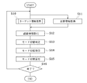
- FIG. 12 is a flowchart showing the operation of the radar system 2 according to the embodiment. The operation of the radar system 2 will be described using this flowchart.
- the radar system 2 performs the target information acquisition process (S10) by the radar device 1 and the image information acquisition process (S11) by the camera 20 in parallel.
- the timing of these processes does not have to be executed at exactly the same time, but is executed synchronously or asynchronously.
- the acquired target information and image information are transmitted to the recognizer 22.
- the radar device 1 and the camera 20 operate in synchronization with each other, and the information acquired at the timing considered to be the same time (for example, the same frame at the frame rate of the radar system 2 as a whole) is transferred to the recognizer 22. You may send it.
- the recognizer 22 executes the recognition process based on the received target information and image information, and acquires the recognition information (S12).
- the recognizer 22 performs recognition of an object based on image information. For example, it performs recognition of people, cars, signs, traffic lights, trees, and other obstacles. This execution may be implemented by, for example, rule-based processing for extracting features, statistical processing, or the like, or may be implemented using a trained model such as a neural network including a deep neural network.
- the recognizer 22 associates the recognized object with the target information, acquires the distance information to each recognized object, and generates the recognition information. The recognizer 22 feeds back this recognition information to the radar device 1.
- the processor 17 of the radar device 1 executes the signal propagation path at the front end, that is, the mode switching determination process based on the received recognition information (S13).
- the mode switching determination process is a process of determining which mode is desirable from the received recognition information.
- the processor 17 may also receive the state of the own vehicle in addition to the recognition information, and make this switching determination based on the state of the own vehicle.
- the processor 17 may determine that the vehicle is moving at a high speed, for example, moving on a highway, and may determine that the first mode is used.
- the speed of the own vehicle may be measured, for example, based on the image information or recognition information of the past several frames and the current frame, or the speed information of the own vehicle acquired by CAN (Controller Area Network) or the like is used. May be good.
- CAN Controller Area Network
- the radar device 1 can acquire target information at a high frame rate.
- the vehicle may be equipped with a speed sensor.
- the processor 17 determines, for example, a case where the number of objects detected in the recognition information is less than a predetermined number, or a case where the number of objects detected within a predetermined distance is less than a predetermined number, and the speed of the own vehicle is predetermined. If it is less than the speed, it may be determined that the vehicle is traveling on a road with good visibility, and it may be determined that the second mode is used. By setting in this way, the radar device 1 can acquire target information farther.
- the processor 17 has an obstacle such as a town. It may be determined that the vehicle is traveling on many roads and that the third mode is used. By setting in this way, the radar device 1 can acquire target information in a state where noise is reduced, that is, in a state where noise and an object can be discriminated more accurately.
- the processor 17 of the radar device 1 sends a mode switching signal to the front end and gives an instruction to switch the mode (S14).
- the mode is appropriately changed based on the control signal output from the processor 17 (S15).
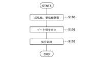
- FIG. 13 is a flowchart showing the processing of S10.
- the processor 17 outputs a control signal for driving to the transmitter 10 and the receiver 11 to drive the transmitter 10 and the receiver 11 (S100).
- the front end outputs a beat signal based on the above processing (S101).
- the processor 17 executes signal processing based on the I signal or the I signal and the Q signal output from the front end (S102).
- this processing for example, FFT (Fast Fourier Transform) processing, various filter processing, noise reduction processing, etc. are appropriately executed for the beat signal output from the front end, and the distance information for each object is obtained from the acquired frequency information. Includes processing to get.
- FFT Fast Fourier Transform
- filters various filter processing, noise reduction processing, etc.
- filters processing to get may be mode-based processes.
- the radar device 1 generates target information and outputs it to the recognizer 22.
- At least a part of the processes described as the processes of the processor 17 and the recognizer 22 is realized by a dedicated circuit such as an ASIC (Application Specific Integrated Circuit).
- a dedicated circuit such as an ASIC (Application Specific Integrated Circuit).
- ASIC Application Specific Integrated Circuit
- at least a part of the information processing by software may be concretely realized by using hardware resources.
- These circuits may be analog or digital circuits. Further, a part of these circuits may be formed by a programmable circuit such as FPGA (Field Programmable Gate Array).
- the radar device 1 or the radar system 2 may be appropriately provided with a memory or storage for temporarily or non-temporarily storing image information, target information, recognition information, and the like.
- a program for executing software may also be stored in this storage or the like, and may be concretely realized by using hardware resources by appropriately reading it by a processing circuit.
- a transmitter that transmits a transmitted wave whose frequency changes continuously, A receiver that receives the reflected wave in the object of the transmitted wave, and At least two mixers that mix the transmitted wave and the reflected wave, and With the processor Equipped with The processor A mode in which the transmitted wave and the reflected wave are mixed in the same phase in the one mixer, and a mode in which the transmitted wave and the reflected wave are mixed in the same phase and different phases in the two mixers. , To switch Radar device.
- the processor In the first mode, in which the transmitted wave and the reflected wave are mixed in the same phase for analog-to-digital conversion in one of the mixers, In the two mixers, the transmitted wave and the reflected wave are mixed in the same phase, antialiased and analog-digitally converted, and the transmitted wave and the reflected wave are mixed in different phases and antialiased. In the second mode, which converts from analog to digital, In the two mixers, the transmitted wave and the reflected wave are mixed in the same phase for analog-digital conversion, and the transmitted wave and the reflected wave are mixed in different phases for analog-digital conversion. , 3rd mode and To switch, The radar device according to (1).
- the processor Select the first mode when the speed of the user is faster than the predetermined speed.
- the radar device according to (3).
- the processor Switching between the first mode, the second mode, or the third mode based on the number of objects that have received the reflected wave.
- the radar device according to (3) or (4).
- the processor When the number of the objects is larger than the predetermined number, the third mode is selected.
- the radar device according to (5).
- the different phases are 90 degrees different from the same phase.
- the radar device according to any one of (1) to (6).
- the radar device according to any one of (1) to (7) and A camera that acquires image information about the surrounding environment, Based on the target information including the position information of the object output from the radar device and the image information output from the camera, the recognition information obtained by recognizing the object and adding the position information of the object is added. To calculate, the recognizer, A radar system.
- the aspect of the present disclosure is not limited to the above-mentioned embodiment, but also includes various possible modifications, and the effect of the present disclosure is not limited to the above-mentioned contents.
- the components in each embodiment may be applied in appropriate combinations. That is, various additions, changes and partial deletions are possible without departing from the conceptual idea and purpose of the present disclosure derived from the contents specified in the claims and their equivalents.
Landscapes
- Engineering & Computer Science (AREA)
- Radar, Positioning & Navigation (AREA)
- Remote Sensing (AREA)
- Physics & Mathematics (AREA)
- General Physics & Mathematics (AREA)
- Computer Networks & Wireless Communication (AREA)
- Electromagnetism (AREA)
- Radar Systems Or Details Thereof (AREA)
- Traffic Control Systems (AREA)
Abstract
[課題]種々の条件において要求性能を満たす。 [解決手段]レーダー装置は、送信機と、受信機と、混合器と、プロセッサと、を備える。送信機は、連続的に周波数が変化する送信波を送信する。受信機は、前記送信波の物体における反射波を受信する。混合器は、前記送信波と、前記反射波と、を混合する。プロセッサは、1つの前記混合器において、前記送信波と前記反射波とを同位相で混合するモードと、2つの前記混合器において、前記送信波と前記反射波とを同位相及び異なる位相で混合するモードと、を切り替える。
Description
本開示は、レーダー装置及びレーダーシステムに関する。
レーダーは、例えば、自動車運転中における安全を確保するための警告や自動運転技術への応用等には欠かせない技術である。従来、レーダーは、ビート信号の出力モードが単一モードである。このようなレーダーにおいては、条件の異なる様々なシーンにおける物体検出精度、物体検出頻度を高めようとすると、演算量及びデータ転送量が大きくなる。このため、レーダーが受信した信号の信号処理の負荷が大きくなり、また、高速な処理が求められる。これらに対応するためには、膨大なコストが掛かるという問題がある。
そこで、本開示では、種々の条件において要求される性能を満たすレーダー装置を提供する。
一実施形態によれば、レーダー装置は、連続的に周波数が変化する送信波を送信する、送信機と、前記送信波の物体における反射波を受信する、受信機と、前記送信波と、前記反射波と、を混合する、少なくとも2つの混合器と、プロセッサと、を備え、前記プロセッサは、1つの前記混合器において、前記送信波と前記反射波とを同位相で混合するモードと、2つの前記混合器において、前記送信波と前記反射波とを同位相及び異なる位相で混合するモードと、を切り替える。
前記プロセッサは、1つの前記混合器において、前記送信波と前記反射波とを同位相で混合してアナログ-デジタル変換する、第1モードと、2つの前記混合器において、前記送信波と前記反射波とを同位相で混合し、アンチエイリアスしてアナログ-デジタル変換し、かつ、前記送信波と前記反射波とを異なる位相で混合し、アンチエイリアスしてアナログ-デジタル変換する、第2モードと、2つの前記混合器において、前記送信波と前記反射波とを同位相で混合してアナログ-デジタル変換し、かつ、前記送信波と前記反射波とを異なる位相で混合してアナログ-デジタル変換する、第3モードと、を切り替えてもよい。
前記プロセッサは、自らの速度に基づいて、前記第1モード、前記第2モード、又は、前記第3モードを切り替えてもよい。
前記プロセッサは、所定速度よりも前記自らの速度が速い場合に、前記第1モードを選択してもよい。
前記プロセッサは、前記反射波を受信した前記物体の数に基づいて、前記第1モード、前記第2モード、又は、前記第3モードを切り替えてもよい。
前記プロセッサは、前記物体の数が所定数よりも多い場合に、前記第3モードを選択してもよい。
前記異なる位相は、同位相とは90度異なる位相であってもよい。
レーダーシステムは、上記のいずれかに記載のレーダー装置と、周辺の環境について画像情報を取得する、カメラと、前記レーダー装置から出力される前記物体の位置情報を含むターゲット情報と、前記カメラから出力される前記画像情報と、に基づいて、前記物体を認識し、前記物体の位置情報を付加した認識情報を算出する、認識器と、を備える。
前記画像情報に基づいた自らの速度に基づいて、前記モードを切り替えてもよい。
前記認識情報における前記物体の数に基づいて、前記モードを切り替えてもよい。
以下、図面を参照して本開示における実施形態の説明をする。図面は、説明のために用いるものであり、実際の装置における各部の構成の形状、サイズ、又は、他の構成とのサイズの比等が図に示されている通りである必要はない。また、図面は、簡略化して書かれているため、図に書かれている以外にも実装上必要な構成は、適切に備えるものとする。また、説明において「以上」「以下」等の記載があるかもしれないが、これは適宜「より大きい(多い、高い)」「より小さい(少ない、低い)」と適切に相互に読み替えることが可能である。
本開示においては、FMCW(Frequency Modulated Continuous Wave)レーダーの態様について説明する。FMCWレーダーは、連続的に波長が変化する連続波を用い、ビート信号(送信波と反射波の周波数差)から距離、方向、相対速度を求めるレーダーである。このレーダーは、例えば、自動車等の移動体の前方に向けて搭載されてもよい。これには限られず、空間に対して固定のものであってもよいが、以下においては移動体、特に自動車の例を用いて説明するが、実施形態は、自動車以外にも適切に利用することが可能である。
図1は、一実施形態に係るレーダー装置の一部であるレーダーモジュールを模式的に示すブロック図である。レーダー装置1は、送信機10と、受信機11と、発振器12と、複数の混合器13と、位相変調器14と、複数のアンチエイリアスフィルタ(以下、AAFと記載する。)15と、アナログ-デジタル変換器(以下、ADCと記載する。)16と、プロセッサ17と、を備える。このレーダー装置1は、上記のFMCWレーダーを用いて物体までの距離、方向、相対速度を測定する装置である。破線で囲まれている部分は、所謂フロントエンドと呼ばれるものであり、例えば、1つのICチップにより形成されてもよい。
送信機10は、例えば、パワーアンプと、送信アンテナと、を備える。送信機10は、発振器12が出力した信号を、例えば、パワーアンプにより適切な強度に変換して、送信アンテナを介して外部へと送信する。
受信機11は、例えば、受信アンテナと、低ノイズアンプと、を備える。受信機11は、物体により反射された発振器12が出力した信号を、例えば、受信アンテナにより受信して、低ノイズアンプにより適切な強度に増幅して出力する。
発振器12は、例えば、局部発振器(Local Oscillator)である。この発振器12は、例えば、時間に対して線形に周波数が単調増加する信号(チャープ信号)を送信波として発振する。このチャープ信号は、周波数が、第1所定周波数から、第1所定周波数よりも高い第2所定周波数までを所定時間の間に線形に増加する信号である。チャープ信号は、周波数が第2所定周波数となると、第1周波数に戻り、繰り返される。発振器12は、送信機10のパワーアンプにこのチャープ信号を出力し、増幅された信号は、送信アンテナを介して空間、例えば、移動体の前方の空間へと送信される。また、発振器12は、送信機10へと信号を送るとともに、複数の混合器13にもこのチャープ信号を出力する。
混合器13は、所謂ミキサ(マルチプライヤ)であり、レーダー装置1内に複数備えられる。そのうちの1つである第1混合器13Aは、発振器12から出力された信号と、受信機11が受信した信号とを混合して出力する。別の1つである第2混合器13Bは、位相変調器14により位相が変調された発振器12から出力された信号と、受信機11が受信した信号とを混合して出力する。
位相変調器14は、入力された信号の位相を変調して出力する。例えば、位相変調器14は、発振器12から出力されたチャープ信号の位相を90度ずらして、第2混合器13Bへと出力する。送信信号の周波数がφ(t)で与えられる場合、発振器12は、cos(φ(t))の信号を送信信号として生成する。この送信信号に対して、位相変調器14は、90度ずらした信号として、sin(φ(t))を生成して出力する。
この組合せによれば、第1混合器13Aからは、送信波と受信波が混合されたI信号が出力され、第2混合器13Bからは、送信波を90度変調した信号と受信波が混合されたQ信号が出力される。後述するように、これらの混合器13の出力を切り替えることにより、I信号だけを出力するrealモードと、I信号及びQ信号の双方を出力するcomplexモードと、が定義される。
AAF 15は、サンプリング周波数に対するナイキスト周波数までの信号を適切に取得するためのアンチエイリアスフィルタである。第1AAF 15Aは、第1混合器13Aが出力したI信号に対してアンチエイリアス処理をするフィルタであり、第2AAF 15Bは、第2混合器13Bが出力したQ信号に対してアンチエイリアス処理をするフィルタである。
AAF 15は、入力された信号に対して所定の処理を施すため、処理時間が発生する一方で、ナイキスト周波数よりも大きい周波数領域におけるサンプリングに起因するノイズを低減することができる。後述するように、レーダー装置1は、AAF 15を利用する場合の利点と、利用しない場合の利点を、それぞれモードとして切り替えて使用する。
ADC 16は、アナログ信号をデジタル信号へと変換する変換器である。第1ADC 16Aは、第1混合器13Aが出力した信号を処理し、第2ADC 16Bは、第2混合器13Bが出力した信号を処理する。
プロセッサ17は、レーダー装置1における信号処理等の処理と、制御処理と、を実行する。プロセッサ17は、例えば、CPU(Central Processing Unit)等の汎用のプロセッサであってもよい。また、信号処理を実現する回路と、制御等を実現する回路とは別々に実装されているものであってもよい。信号処理を実現する回路は、各種アクセラレータを用いて信号処理を高速化していてもよい。
プロセッサ17は、ADC 16が出力した信号に対して適切な信号処理を施し、ユーザに対して出力したり、自動運転を実行するためのパラメータ等を出力したりする。また、プロセッサ17は、信号処理した結果に基づいて、レーダー装置1のフロントエンド部分の制御を実行する。例えば、realモードで距離測定等を実行するのに適している場合には、位相変調器14、第2混合器13B、第1AAF 15A、第2AAF 15B、第2ADC 16Bの処理を停止してもよい。モードの制御の詳細については、後述する。このように、プロセッサ17は、適切にレーダー装置1の出力、及び、制御を実行する。
レーダー装置1は、上記のように、取得された物体の距離等の情報に基づいて、制御モードを切り替える。
図2は、一実施形態に係る第1モードの動作におけるレーダー装置1の信号の流れを示す図である。以下、図2、図4、図6の各図において、プロセッサ17は、実線で示す経路で信号が伝播し、点線で示す経路においては各処理を実行しないように制御をする。
第1モードは、上述したrealモードに対応するモードである。発振器12は、送信機10及び第1混合器13Aに送信波であるチャープ信号(送信信号)を出力する。受信機11により受信され適切に増幅された反射波(受信信号)は、第1混合器13Aに入力される。第1混合器13Aは、受信信号と、位相変調をしていない送信信号とを混合したビート信号を、第1ADC 16Aへと出力する。第1ADC 16Aでは、ビート信号に対して適切な信号処理を実行し、物体との距離等の情報を取得する。
このような処理の流れの結果、第1モードにおいては、送信信号であるcos(φ(t))と受信信号との混合が実行される。このため、サンプリング周波数fsに対して、ナイキストレートを考慮して、[0, fs/2]における情報、すなわち、この範囲に対応する距離情報を適切に取得することができる。
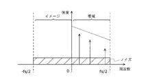
図3は、取得されたビート信号をフーリエ変換したスペクトルの一例を示す図である。中心となる周波数は、送信信号の周波数となり、対応するビート信号の周波数(ビート周波数)に対して、図3に示すように、[-fs/2, fs/2]の区間にスペクトルとして現れる。グラフ中の矢印がスペクトルを示す。
ビート信号は、例えば、送信波を反射した物体ごとに取得することができる。このため、図に示すように、異なる距離にある複数の物体からの反射波に係るビート周波数におけるスペクトルを取得することができる。
この第1モードでは、位相変調器14、第2混合器13B、第1AAF 15A、第2AAF 15B、第2ADC 16Bにおける処理についての電力の消費を削減することが可能となる。また、これらの処理を実行する必要が無いので、これらの処理を行う場合と比較して処理速度を向上させることができる。
一方で、図に示すように、実数領域の帯域に起因するノイズ(右上がりの斜線部分)と、ミラー領域の帯域に起因するノイズ(左上がりの斜線部分)が発生するため、信号に対するノイズの影響が大きくなる。また、距離を検出できる範囲の最大値が、サンプリング周波数の1/2となる。
図4は、一実施形態に係る第2モードの動作におけるレーダー装置1の信号の流れを示す図である。
第2モードは、上述したcomplexモードの1つに対応するモードである。発振器12は、送信機10及び第1混合器13Aに送信信号を出力するとともに、位相変調器14を介して第2混合器13Bにも送信信号を出力する。第1混合器13Aにおいては、受信信号と位相変調をしていない送信信号とが乗算される。一方で、第2混合器13Bにおいては、受信信号と90度位相シフトされた送信信号とが乗算される。
第1混合器13Aから出力された信号は、第1AAF 15Aにおいてアンチエイリアス処理が実行され、第2混合器13Bから出力された信号は、第2AAF 15Bにおいてアンチエイリアス処理が実行される。その後、それぞれのAAF 15から出力された信号は、それぞれに対応するADC 16においてアナログ-デジタル変換され、プロセッサ17へと出力される。
このような処理の流れの結果、第2モードにおいては、送信信号と同相データであるcos(φ(t))に対する直行データsin(φ(t))も考慮され、プロセッサ17は、cos(φ(t)) + j sin(φ(t))という複素数との積算結果を取得することができる。より詳しくは、第1混合器13Aからは、I成分であるcos(φ(t))との積、第2混合器13Bからは、Q成分であるsin(φ(t))との積が出力される。そして、これらの出力された信号は、AAF 15によりイメージ成分が除去される。
図5は、取得されたビート信号をフーリエ変換したスペクトルの一例を示す図である。中心となる周波数は、送信信号の周波数となり、対応するビート信号の周波数に対して、[0, fs]の区間にスペクトルとして現れる。
アンチエイリアス処理により周波数の正の成分に対するデータを取得することにより、イメージ成分が除去され、この除去をすることにより、イメージ成分(負の周波数成分)のノイズが除去される。さらに、イメージ成分の除去に伴い、イメージ成分の周波数帯域を有効に利用することが可能となるため、サンプリング周波数と同等の帯域において、距離を測定することが可能となる。
この第2モードでは、第1モードと比較すると、第2混合器13B、位相変調器14、AAF 15、第2ADC 16Bを駆動するので、処理するデータ量が倍となり消費電力及び処理速度の点において第1モードよりも劣る。
一方で、第2モードにおいては、サンプリングレートは、ナイキストレートに基づいて取得したい帯域の2倍まで増大させる必要が無い。換言すると、サンプリングレートが同じ場合、第2モードは、最大で第1モードの倍の距離までの解像度を有する。また、上述したようにイメージ成分のノイズが除去されるので、第2モードは、第1モードに比べて重畳されるノイズが少なくなる利点もある。
図6は、一実施形態に係る第3モードの動作におけるレーダー装置1の信号の流れを示す図である。
第3モードは、上述したcomplexモードの1つに対応するモードである。発振器12は、送信機10及び第1混合器13Aに送信信号を出力するとともに、位相変調器14を介して第2混合器13Bにも送信信号を出力する。第1混合器13Aにおいては、受信信号と位相変調をしていない送信信号とが乗算される。一方で、第2混合器13Bにおいては、受信信号と90度位相シフトされた送信信号とが乗算される。
第1混合器13Aから出力された信号は、第1ADC 16Aにおいてアナログ-デジタル変換され、第2混合器13Bから出力された信号は、第2ADC 16Bにおいてアナログ-デジタル変換される。
このような処理の流れの結果、第3モードにおいては、第2モードと同様に、プロセッサ17は、cos(φ(t)) + j sin(φ(t))という複素数との積算結果を取得することができる。より詳しくは、第1混合器13Aからは、I成分であるcos(φ(t))との積、第2混合器13Bからは、Q成分であるsin(φ(t))との積が出力される。第2モードとは異なり、アンチエイリアスすること無く、信号がプロセッサ17へと出力される。
図7は、取得されたビート信号をフーリエ変換したスペクトルの一例を示す図である。中心となる周波数は、送信信号の周波数となり、対応するビート信号の周波数に対して、[0, fs/2]の区間にスペクトルとして現れる。
第2モードとは異なり、第3モードにおいては、負の周波数成分も出力される。FMCWレーダーの特性上、受信信号の周波数は、発振器12の発振する周波数よりも低い(チャープ信号が単調増加する場合)ので、負の周波数成分には有効なデータが含まれず、ノイズのみが含まれることとなる。このため、この負の周波数成分を観測することにより、ノイズの大きさを検出することが可能となる。
一方で、第2モードと比較すると、負の周波数成分を除去しない、すなわち、イメージ成分がデータとして取得されるため、有意なデータは、第1モードと同様に、ナイキストレートにより最大でサンプリング周波数の半分であるfs / 2となる。
上記したそれぞれのモードについて、以下のように要点をまとめることができる。
第1モードは、反射波に対してI成分のみを出力し、検出可能な最大のビート周波数は、fs / 2となる。第2モード、第3モードと比較すると、処理するデータ量が少ないため、後段の信号処理が高速(高フレームレート)であり、低電力である。このため、第2モード、第3モードよりも、移動体が高速で移動しており、物体検出の頻度(フレームレート)を高く維持したい場合に有効である。
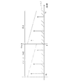
図8は、一例として、高速道路を走行している自動車において取得される画像である。このような場合に、第1モードが他のモードよりも有効となる。
第2モードは、反射波に対してI成分、Q成分を出力し、これらの出力における正の周波数成分のみを出力する。検出可能な最大ビート周波数は、fsとなる。第1モードと比較するとノイズが少なく、また、第1モード、第3モードと比較すると、最大ビート周波数が2倍となり、検出可能距離が2倍となる。このため、第1モード、第3モードよりも、見通しがよく、低フレームレートでもよいが、遠方まで検出したい場合に有効である。
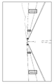
図9は、一例として、見通しのよい道を走行している自動車において取得される画像である。このように、遠方まで見渡せる状態で、より遠くにある標識、より遠くにいる人等を検出したい場合には、第2モードが他のモードよりも有効となる。
第3モードは、反射波に対してI成分、Q成分を出力し、これらの出力における正負双方の周波数成分のみを出力する。検出可能な最大ビート周波数は、fs / 2となる。第1モードと比較するとノイズが少なく、また、第2モードと比較すると、ノイズ成分の大きさが検出可能となる。このため、正の周波数成分におけるノイズの大きさを推定することができ、すなわち、物体とノイズとをより精度よく分離することができる。この結果、第1モード、第3モードよりも、ノイズと物体とを明確に区別することが求められる、検出する物体が多い場合に有効である。
図10は、一例として、自動車において取得された情報において、検出される対象が比較的多い場合の画像である。このように、例えば、町中のように、検出される対象が多い場合には、第3モードが他のモードよりも有効となる。
このように、3つのモードを切り分けることにより、プロセッサ17による信号処理の負荷を抑制しつつ、それぞれのシーンで求められる性能を満たすレーダーを構成することができる。換言すると、それぞれのモードには、メリットとデメリットとが存在するが、他のモードにおけるデメリットをカバーであるようなモードを適切に選択することが可能となる。
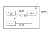
図11は、上述したレーダー装置1を備えるレーダーシステムの構成例を示す図である。
レーダーシステム2は、レーダー装置1と、カメラ20と、認識器22と、を備える。
レーダー装置1は、上述に説明したように、プロセッサ17の制御により、第1モード、第2モード、第3モードを適切に切り替えて、物体までの距離等に関する情報を取得する。
図11及び図1に示すように、レーダー装置1は、プロセッサ17において、フロントエンドが出力した情報に基づいてターゲット情報を出力し、認識器22が出力した認識情報に基づいてフロントエンドのモード制御を実行する。プロセッサ17は、例えば、信号処理部と制御部と、を別々に備えていてもよい。このように機能ごとに別途回路が備えられる場合には、信号処理部は、フロントエンドが出力した「Iデータ」又は「Iデータ及びQデータ」に基づいて物体までの距離等の情報であるターゲット情報を出力する。制御部は、認識器22が出力された認識情報に基づいて、フロントエンドにおけるデータを取得するためのモードを適切に切り替える。
ターゲット情報とは、上述したレーダー装置1の説明における物体に関する情報、例えば、距離等の情報のことである。プロセッサ17は、各モードに基づいた処理を実行し、物体までの位置を算出してもよい。例えば、第1モードであれば、正の周波数成分のみを処理することにより、演算を高速化することができる。第3モードであれば、負の周波数成分からノイズ量を推定し、正の周波数成分に対して推定したノイズ量を閾値として用いることにより、物体判別(ビート周波数抽出)の精度をより高くしてもよい。
カメラ20は、周辺、例えば、自動車の前方の情報を画像情報として取得する。カメラ20は、取得した画像情報を、認識器22へと出力する。また、前方だけではなく、側方、後方等、必要な情報を取得するために複数のカメラ20が備えられていてもよい。
認識器22は、カメラ20から取得した画像情報を用いて物体(ターゲット)の認識処理を実行し、この認識処理された情報と、レーダー装置1から取得したターゲット情報に基づいて、認識されたターゲットまでの距離を算出し、認識情報として取得する。取得した認識情報は、図示しない出力インタフェースを介して外部へと出力、例えば、ナビゲーション装置のディスプレイ等に出力されるとともに、レーダー装置1へと出力される。
認識情報とは、このように認識器22により解析された画像における人物、移動体、標識、障害物等の物体の位置に関する情報を含む。
レーダー装置1のプロセッサ17は、受信した認識情報に基づいて、図1に示す制御信号を生成する。この制御信号は、フロントエンドにおけるモードの切り替えを制御する信号である。レーダー装置1は、このように認識情報に基づいて制御信号を生成し、モードを切り替えることによりターゲットの情報を、効率よく、かつ、精度よく取得する。
モードの切り替えは、例えば、フロントエンドにおける信号の経路のスイッチを切り替えることにより実現されてもよい。例えば、第1モードにおいては、発振器12と位相変調器14との間に備えられるスイッチをオフし、かつ、第1混合器13Aから第1ADC 16Aに接続されるようにスイッチを切り替える。第2モードにおいては、混合器13からAAF 15に接続されるようにスイッチを切り替える。第3モードにおいては、混合器13からADC 16に接続されるようにスイッチを切り替える。このようにスイッチを切り替えることにより、モードの切り替えを実現することができる。スイッチは、例えば、MOSFET(Metal-Oxide-Semiconductor Field-Effect Transistor)等のアナログスイッチにより実装されてもよいし、別の構成で適切に切り替えが実現できる素子により実装されてもよい。
また、プロセッサ17は、これらの経路、及び/又は、各処理ブロックの切り替えとともに、送信機10と受信機11の動作タイミングを制御してもよい。例えば、ターゲット情報と画像情報との間に齟齬があり、否定妨害等の電波妨害を認識器22において検知した場合には、プロセッサ17は、動作タイミングをずらすことにより、同期できる信号を選択的に取得してもよい。
このように、レーダーシステム2は、レーダー装置1のモードの切り替え等を適切に実行するべく構成される。
図12は、一実施形態に係るレーダーシステム2の動作を示すフローチャートである。このフローチャートを用いて、レーダーシステム2の動作について説明する。
まず、レーダーシステム2は、レーダー装置1によるターゲット情報の取得処理(S10)と、カメラ20による画像情報取得処理(S11)を並行して行う。これらの処理のタイミングは、厳密に同じ時刻に実行される必要は無く、同期して又は非同期で実行される。取得されたターゲット情報及び画像情報は、認識器22へと送信される。一例として、レーダー装置1とカメラ20とは、同期して動作し、同じ時刻とみなされるタイミング(例えば、レーダーシステム2全体としてのフレームレートにおける同じフレーム)において取得された情報を認識器22へと送信してもよい。
次に、認識器22は、受信したターゲット情報及び画像情報に基づいて認識処理を実行し、認識情報を取得する(S12)。まず、認識器22は、画像情報に基づいて物体の認識を実行する。例えば、人物、自動車、標識、信号、樹木、その他障害物等の認識を実行する。この実行は、例えば、特徴量を抽出したルールベースの処理、統計処理等により実装されてもよいし、ディープニューラルネットワークを含むニューラルネットワーク等の学習済モデルを用いて実装されてもよい。物体の認識処理の後、認識器22は、認識された物体と、ターゲット情報とを紐付け、認識されたそれぞれの物体までの距離情報を取得し、認識情報を生成する。認識器22は、この認識情報をレーダー装置1へとフィードバックする。
次に、レーダー装置1のプロセッサ17は、受信した認識情報に基づいて、フロントエンドにおける信号の伝搬経路、すなわち、モードの切り替えの判定処理を実行する(S13)。モードの切り替えの判定処理とは、受信した認識情報から、どのモードを適用するのが望ましいかを判定する処理である。プロセッサ17はまた、認識情報の他に、自車両の状態を受信し、この自車両の状態にも基づいてこの切り替え判定をしてもよい。
プロセッサ17は、例えば、自車両の速度が所定速度以上であれば、高速で移動中、例えば、高速道路を移動していると判定し、第1モードを利用すると判定してもよい。自車両の速度は、例えば、過去数フレーム及び現フレームの画像情報又は認識情報に基づいて計測されてもよいし、CAN(Controller Area Network)等により取得された自車両の速度情報が用いられてもよい。このように設定することにより、レーダー装置1は、高フレームレートのターゲット情報を取得することが可能となる。CANを用いる場合には、車両に速度センサが備えられていてもよい。
プロセッサ17は、例えば、認識情報において検出されている物体が所定数よりも少ない場合、又は、所定距離内において検出されている物体が所定数よりも少ない場合であって、自車両の速度が所定速度未満であれば、見通しがよい道路を走行していると判定し、第2モードを利用すると判定してもよい。このように設定することにより、レーダー装置1は、より遠くまでのターゲット情報を取得することが可能となる。
プロセッサ17は、例えば、認識情報において検出されている物体が所定数以上である場合、又は、所定距離内において検出されている物体が所定数以上である場合、自車両が町中等の障害物が多い道路を走行していると判定し、第3モードを利用すると判定してもよい。このように設定することにより、レーダー装置1は、ノイズを低減した状態、すなわち、ノイズと物体をより精度よく判別可能な状態のターゲット情報を取得することが可能となる。
次に、レーダー装置1のプロセッサ17は、モード切替信号をフロントエンドに送信し、モード切替の指示をする(S14)。
次に、フロントエンドにおいて、プロセッサ17から出力された制御信号に基づいて適切にモードが変更される(S15)。
この後、処理が終了であれば(S16:YES)、処理を終了し、終了でなければ(S16:YES)、S10、S11からの処理を繰り返す。
図13は、S10の処理を示すフローチャートである。
まず、プロセッサ17は、送信機10及び受信機11に対して駆動のための制御信号を出力し、送信機10及び受信機11を駆動する(S100)。
次に、フロントエンドは、上述した処理に基づいてビート信号を出力する(S101)。
次に、プロセッサ17は、フロントエンドから出力されたI信号、又は、I信号及びQ信号に基づいて、信号処理を実行する(S102)。この処理は、例えば、フロントエンドから出力されたビート信号に対して適切にFFT(Fast Fourier Transform)処理、各種フィルタ処理、ノイズ除去処理等を実行し、取得された周波数情報から物体ごとの距離情報を取得する処理を含む。これらの処理は、モードに基づく処理であってもよい。
このように、レーダー装置1は、ターゲット情報を生成し、認識器22へと出力する。
以上のように、本実施形態によれば、移動体自身の環境又は周囲の環境に基づいてモードを切り替えることにより、適切に精度のよいターゲットの位置推定ができるとともに、消費電力を削減することが可能となる。
なお、前述の実施形態において、プロセッサ17、認識器22の処理として記載されている各処理は、少なくとも一部の処理がASIC(Application Specific Integrated Circuit)等の専用回路により実現されるものであってもよいし、少なくとも一部がソフトウェアによる情報処理がハードウェア資源を用いて具体的に実現されるものであってもよい。これらの回路は、アナログ又はデジタルの回路であってもよい。また、これらの回路のうち一部は、FPGA(Field Programmable Gate Array)等のプログラマブルな回路により形成されていてもよい。
また、図示していないが、画像情報、ターゲット情報、認識情報等を一時的又は非一時的に格納するメモリ又はストレージ等がレーダー装置1又はレーダーシステム2には適切に備えられてもよい。ソフトウェアを実行するためのプログラムも、このストレージ等に格納され、処理回路により適切に読み出すことによりハードウェア資源を用いて具体的に実現されるものであってもよい。
前述した実施形態は、以下のような形態としてもよい。
(1)
連続的に周波数が変化する送信波を送信する、送信機と、
前記送信波の物体における反射波を受信する、受信機と、
前記送信波と、前記反射波と、を混合する、少なくとも2つの混合器と、
プロセッサと、
を備え、
前記プロセッサは、
1つの前記混合器において、前記送信波と前記反射波とを同位相で混合するモードと、2つの前記混合器において、前記送信波と前記反射波とを同位相及び異なる位相で混合するモードと、を切り替える、
レーダー装置。
連続的に周波数が変化する送信波を送信する、送信機と、
前記送信波の物体における反射波を受信する、受信機と、
前記送信波と、前記反射波と、を混合する、少なくとも2つの混合器と、
プロセッサと、
を備え、
前記プロセッサは、
1つの前記混合器において、前記送信波と前記反射波とを同位相で混合するモードと、2つの前記混合器において、前記送信波と前記反射波とを同位相及び異なる位相で混合するモードと、を切り替える、
レーダー装置。
(2)
前記プロセッサは、
1つの前記混合器において、前記送信波と前記反射波とを同位相で混合してアナログ-デジタル変換する、第1モードと、
2つの前記混合器において、前記送信波と前記反射波とを同位相で混合し、アンチエイリアスしてアナログ-デジタル変換し、かつ、前記送信波と前記反射波とを異なる位相で混合し、アンチエイリアスしてアナログ-デジタル変換する、第2モードと、
2つの前記混合器において、前記送信波と前記反射波とを同位相で混合してアナログ-デジタル変換し、かつ、前記送信波と前記反射波とを異なる位相で混合してアナログ-デジタル変換する、第3モードと、
を切り替える、
(1)に記載のレーダー装置。
前記プロセッサは、
1つの前記混合器において、前記送信波と前記反射波とを同位相で混合してアナログ-デジタル変換する、第1モードと、
2つの前記混合器において、前記送信波と前記反射波とを同位相で混合し、アンチエイリアスしてアナログ-デジタル変換し、かつ、前記送信波と前記反射波とを異なる位相で混合し、アンチエイリアスしてアナログ-デジタル変換する、第2モードと、
2つの前記混合器において、前記送信波と前記反射波とを同位相で混合してアナログ-デジタル変換し、かつ、前記送信波と前記反射波とを異なる位相で混合してアナログ-デジタル変換する、第3モードと、
を切り替える、
(1)に記載のレーダー装置。
(3)
前記プロセッサは、
自らの速度に基づいて、前記第1モード、前記第2モード、又は、前記第3モードを切り替える、
(2)に記載のレーダー装置。
前記プロセッサは、
自らの速度に基づいて、前記第1モード、前記第2モード、又は、前記第3モードを切り替える、
(2)に記載のレーダー装置。
(4)
前記プロセッサは、
所定速度よりも前記自らの速度が速い場合に、前記第1モードを選択する、
(3)に記載のレーダー装置。
前記プロセッサは、
所定速度よりも前記自らの速度が速い場合に、前記第1モードを選択する、
(3)に記載のレーダー装置。
(5)
前記プロセッサは、
前記反射波を受信した前記物体の数に基づいて、前記第1モード、前記第2モード、又は、前記第3モードを切り替える、
(3)又は(4)に記載のレーダー装置。
前記プロセッサは、
前記反射波を受信した前記物体の数に基づいて、前記第1モード、前記第2モード、又は、前記第3モードを切り替える、
(3)又は(4)に記載のレーダー装置。
(6)
前記プロセッサは、
前記物体の数が所定数よりも多い場合に、前記第3モードを選択する、
(5)に記載のレーダー装置。
前記プロセッサは、
前記物体の数が所定数よりも多い場合に、前記第3モードを選択する、
(5)に記載のレーダー装置。
(7)
前記異なる位相は、同位相とは90度異なる位相である、
(1)から(6)のいずれかに記載のレーダー装置。
前記異なる位相は、同位相とは90度異なる位相である、
(1)から(6)のいずれかに記載のレーダー装置。
(8)
(1)から(7)のいずれかに記載のレーダー装置と、
周辺の環境について画像情報を取得する、カメラと、
前記レーダー装置から出力される前記物体の位置情報を含むターゲット情報と、前記カメラから出力される前記画像情報と、に基づいて、前記物体を認識し、前記物体の位置情報を付加した認識情報を算出する、認識器と、
を備える、レーダーシステム。
(1)から(7)のいずれかに記載のレーダー装置と、
周辺の環境について画像情報を取得する、カメラと、
前記レーダー装置から出力される前記物体の位置情報を含むターゲット情報と、前記カメラから出力される前記画像情報と、に基づいて、前記物体を認識し、前記物体の位置情報を付加した認識情報を算出する、認識器と、
を備える、レーダーシステム。
(9)
前記画像情報に基づいた自らの速度に基づいて、前記モードを切り替える、
(8)に記載のレーダーシステム。
前記画像情報に基づいた自らの速度に基づいて、前記モードを切り替える、
(8)に記載のレーダーシステム。
(10)
前記認識情報における前記物体の数に基づいて、前記モードを切り替える、
(8)又は(9)に記載のレーダーシステム。
前記認識情報における前記物体の数に基づいて、前記モードを切り替える、
(8)又は(9)に記載のレーダーシステム。
本開示の態様は、前述した実施形態に限定されるものではなく、想到しうる種々の変形も含むものであり、本開示の効果も前述の内容に限定されるものではない。各実施形態における構成要素は、適切に組み合わされて適用されてもよい。すなわち、特許請求の範囲に規定された内容及びその均等物から導き出される本開示の概念的な思想と趣旨を逸脱しない範囲で種々の追加、変更及び部分的削除が可能である。
1:レーダー装置、
10:送信機、11:受信機、12:発振器、13:混合器、14:位相変調器、15:AAF、16:ADC、17:プロセッサ、
2:レーダーシステム、
20:カメラ、22:認識器
10:送信機、11:受信機、12:発振器、13:混合器、14:位相変調器、15:AAF、16:ADC、17:プロセッサ、
2:レーダーシステム、
20:カメラ、22:認識器
Claims (10)
- 連続的に周波数が変化する送信波を送信する、送信機と、
前記送信波の物体における反射波を受信する、受信機と、
前記送信波と、前記反射波と、を混合する、少なくとも2つの混合器と、
プロセッサと、
を備え、
前記プロセッサは、
1つの前記混合器において、前記送信波と前記反射波とを同位相で混合するモードと、2つの前記混合器において、前記送信波と前記反射波とを同位相及び異なる位相で混合するモードと、を切り替える、
レーダー装置。 - 前記プロセッサは、
1つの前記混合器において、前記送信波と前記反射波とを同位相で混合してアナログ-デジタル変換する、第1モードと、
2つの前記混合器において、前記送信波と前記反射波とを同位相で混合し、アンチエイリアスしてアナログ-デジタル変換し、かつ、前記送信波と前記反射波とを異なる位相で混合し、アンチエイリアスしてアナログ-デジタル変換する、第2モードと、
2つの前記混合器において、前記送信波と前記反射波とを同位相で混合してアナログ-デジタル変換し、かつ、前記送信波と前記反射波とを異なる位相で混合してアナログ-デジタル変換する、第3モードと、
を切り替える、
請求項1に記載のレーダー装置。 - 前記プロセッサは、
自らの速度に基づいて、前記第1モード、前記第2モード、又は、前記第3モードを切り替える、
請求項2に記載のレーダー装置。 - 前記プロセッサは、
所定速度よりも前記自らの速度が速い場合に、前記第1モードを選択する、
請求項3に記載のレーダー装置。 - 前記プロセッサは、
前記反射波を受信した前記物体の数に基づいて、前記第1モード、前記第2モード、又は、前記第3モードを切り替える、
請求項3に記載のレーダー装置。 - 前記プロセッサは、
前記物体の数が所定数よりも多い場合に、前記第3モードを選択する、
請求項5に記載のレーダー装置。 - 前記異なる位相は、同位相とは90度異なる位相である、
請求項1に記載のレーダー装置。 - 請求項1に記載のレーダー装置と、
周辺の環境について画像情報を取得する、カメラと、
前記レーダー装置から出力される前記物体の位置情報を含むターゲット情報と、前記カメラから出力される前記画像情報と、に基づいて、前記物体を認識し、前記物体の位置情報を付加した認識情報を算出する、認識器と、
を備える、レーダーシステム。 - 前記画像情報に基づいた自らの速度に基づいて、前記モードを切り替える、
請求項8に記載のレーダーシステム。 - 前記認識情報における前記物体の数に基づいて、前記モードを切り替える、
請求項8に記載のレーダーシステム。
Applications Claiming Priority (2)
| Application Number | Priority Date | Filing Date | Title |
|---|---|---|---|
| JP2020169981A JP2022061809A (ja) | 2020-10-07 | 2020-10-07 | レーダー装置及びレーダーシステム |
| JP2020-169981 | 2020-10-07 |
Publications (1)
| Publication Number | Publication Date |
|---|---|
| WO2022075151A1 true WO2022075151A1 (ja) | 2022-04-14 |
Family
ID=81125831
Family Applications (1)
| Application Number | Title | Priority Date | Filing Date |
|---|---|---|---|
| PCT/JP2021/035879 Ceased WO2022075151A1 (ja) | 2020-10-07 | 2021-09-29 | レーダー装置及びレーダーシステム |
Country Status (2)
| Country | Link |
|---|---|
| JP (1) | JP2022061809A (ja) |
| WO (1) | WO2022075151A1 (ja) |
Citations (9)
| Publication number | Priority date | Publication date | Assignee | Title |
|---|---|---|---|---|
| JPH06235763A (ja) * | 1993-02-08 | 1994-08-23 | Mitsubishi Electric Corp | レーダ装置 |
| JPH08136647A (ja) * | 1994-11-08 | 1996-05-31 | Honda Motor Co Ltd | Fm−cw方式マルチビームレーダー装置 |
| JP2002071792A (ja) * | 2000-08-30 | 2002-03-12 | Hitachi Ltd | レーダ装置および自動車制御システム |
| JP2009205642A (ja) * | 2008-02-29 | 2009-09-10 | Hitachi Ltd | 車両速度判定装置および車両速度判定方法 |
| JP2010151621A (ja) * | 2008-12-25 | 2010-07-08 | Fujitsu Ten Ltd | 信号処理装置、及びレーダ装置 |
| US20120086594A1 (en) * | 2009-06-30 | 2012-04-12 | Robert Bosch Gmbh | Mixer assembly and radar sensor for motor vehicles |
| JP2012173874A (ja) * | 2011-02-18 | 2012-09-10 | Fujitsu Ltd | 距離算出プログラム、距離算出方法及び距離算出装置 |
| JP2014062877A (ja) * | 2012-09-24 | 2014-04-10 | Honda Motor Co Ltd | 物体認識装置 |
| JP2017146100A (ja) * | 2016-02-15 | 2017-08-24 | マツダ株式会社 | レーダ装置を備えた車両 |
-
2020
- 2020-10-07 JP JP2020169981A patent/JP2022061809A/ja active Pending
-
2021
- 2021-09-29 WO PCT/JP2021/035879 patent/WO2022075151A1/ja not_active Ceased
Patent Citations (9)
| Publication number | Priority date | Publication date | Assignee | Title |
|---|---|---|---|---|
| JPH06235763A (ja) * | 1993-02-08 | 1994-08-23 | Mitsubishi Electric Corp | レーダ装置 |
| JPH08136647A (ja) * | 1994-11-08 | 1996-05-31 | Honda Motor Co Ltd | Fm−cw方式マルチビームレーダー装置 |
| JP2002071792A (ja) * | 2000-08-30 | 2002-03-12 | Hitachi Ltd | レーダ装置および自動車制御システム |
| JP2009205642A (ja) * | 2008-02-29 | 2009-09-10 | Hitachi Ltd | 車両速度判定装置および車両速度判定方法 |
| JP2010151621A (ja) * | 2008-12-25 | 2010-07-08 | Fujitsu Ten Ltd | 信号処理装置、及びレーダ装置 |
| US20120086594A1 (en) * | 2009-06-30 | 2012-04-12 | Robert Bosch Gmbh | Mixer assembly and radar sensor for motor vehicles |
| JP2012173874A (ja) * | 2011-02-18 | 2012-09-10 | Fujitsu Ltd | 距離算出プログラム、距離算出方法及び距離算出装置 |
| JP2014062877A (ja) * | 2012-09-24 | 2014-04-10 | Honda Motor Co Ltd | 物体認識装置 |
| JP2017146100A (ja) * | 2016-02-15 | 2017-08-24 | マツダ株式会社 | レーダ装置を備えた車両 |
Also Published As
| Publication number | Publication date |
|---|---|
| JP2022061809A (ja) | 2022-04-19 |
Similar Documents
| Publication | Publication Date | Title |
|---|---|---|
| JP5130034B2 (ja) | 電子走査式レーダ装置 | |
| CN112639519B (zh) | 雷达系统中的两阶段信号处理的装置和方法 | |
| JP5183661B2 (ja) | 車載レーダ装置 | |
| KR101137088B1 (ko) | 통합 레이더 장치 및 통합 안테나 장치 | |
| JP4665962B2 (ja) | 目標物検出装置 | |
| CN109154652B (zh) | 速度检测装置 | |
| EP1365257A2 (en) | Radar system | |
| JP6797334B1 (ja) | レーダ装置、観測対象検出方法および車載装置 | |
| JP2004163340A (ja) | 車載用レーダ装置 | |
| JP2007051888A (ja) | レーダ装置 | |
| CN112639521A (zh) | 用于控制雷达跳频的方法和装置以及雷达测速方法和雷达 | |
| US12174293B2 (en) | Low phase noise radar system | |
| CN111505641A (zh) | 无线电信号发送方法和装置 | |
| KR101727583B1 (ko) | 도플러 레이더 | |
| US20250012905A1 (en) | Fmcw radar and lidar signal processing architecture for autonomous vehicles | |
| JP2006337223A (ja) | レーダ装置 | |
| WO2022075151A1 (ja) | レーダー装置及びレーダーシステム | |
| CN111954826A (zh) | 电子设备、电子设备的控制方法以及电子设备的控制程序 | |
| JP6953490B2 (ja) | 電子機器、電子機器の制御方法、及び電子機器の制御プログラム | |
| JP7313525B2 (ja) | 電子機器、電子機器の制御方法、及び電子機器の制御プログラム | |
| JP2007298305A (ja) | 物体検出装置 | |
| JP2024171412A (ja) | 無線通信装置、無線通信方法および無線通信プログラム | |
| US20250231274A1 (en) | Extended Virtual Array In An Automotive MIMO Radar | |
| US12117515B2 (en) | Fractalet radar processing | |
| CN116940863B (zh) | 雷达装置和具有雷达装置的车载装置 |
Legal Events
| Date | Code | Title | Description |
|---|---|---|---|
| 121 | Ep: the epo has been informed by wipo that ep was designated in this application |
Ref document number: 21877452 Country of ref document: EP Kind code of ref document: A1 |
|
| NENP | Non-entry into the national phase |
Ref country code: DE |
|
| 122 | Ep: pct application non-entry in european phase |
Ref document number: 21877452 Country of ref document: EP Kind code of ref document: A1 |