WO2022074958A1 - 2段変速機 - Google Patents
2段変速機 Download PDFInfo
- Publication number
- WO2022074958A1 WO2022074958A1 PCT/JP2021/031515 JP2021031515W WO2022074958A1 WO 2022074958 A1 WO2022074958 A1 WO 2022074958A1 JP 2021031515 W JP2021031515 W JP 2021031515W WO 2022074958 A1 WO2022074958 A1 WO 2022074958A1
- Authority
- WO
- WIPO (PCT)
- Prior art keywords
- rotating member
- torque
- pressing
- friction plate
- bearing
- Prior art date
Links
- 230000005540 biological transmission Effects 0.000 title claims abstract description 153
- 230000007246 mechanism Effects 0.000 claims abstract description 39
- 230000036316 preload Effects 0.000 claims description 9
- 230000009467 reduction Effects 0.000 abstract description 51
- 238000005096 rolling process Methods 0.000 description 55
- 230000002093 peripheral effect Effects 0.000 description 31
- 230000001133 acceleration Effects 0.000 description 7
- 230000009471 action Effects 0.000 description 7
- 238000006073 displacement reaction Methods 0.000 description 6
- 238000004026 adhesive bonding Methods 0.000 description 5
- 239000003921 oil Substances 0.000 description 4
- 238000006243 chemical reaction Methods 0.000 description 2
- 238000002485 combustion reaction Methods 0.000 description 2
- 230000007423 decrease Effects 0.000 description 2
- 239000002803 fossil fuel Substances 0.000 description 2
- 230000000149 penetrating effect Effects 0.000 description 2
- 238000009954 braiding Methods 0.000 description 1
- 238000010586 diagram Methods 0.000 description 1
- 230000000694 effects Effects 0.000 description 1
- 230000001771 impaired effect Effects 0.000 description 1
- 230000006872 improvement Effects 0.000 description 1
- 230000004044 response Effects 0.000 description 1
- 230000035939 shock Effects 0.000 description 1
- 239000002904 solvent Substances 0.000 description 1
Images


Classifications
-
- F—MECHANICAL ENGINEERING; LIGHTING; HEATING; WEAPONS; BLASTING
- F16—ENGINEERING ELEMENTS AND UNITS; GENERAL MEASURES FOR PRODUCING AND MAINTAINING EFFECTIVE FUNCTIONING OF MACHINES OR INSTALLATIONS; THERMAL INSULATION IN GENERAL
- F16D—COUPLINGS FOR TRANSMITTING ROTATION; CLUTCHES; BRAKES
- F16D23/00—Details of mechanically-actuated clutches not specific for one distinct type
- F16D23/12—Mechanical clutch-actuating mechanisms arranged outside the clutch as such
-
- F—MECHANICAL ENGINEERING; LIGHTING; HEATING; WEAPONS; BLASTING
- F16—ENGINEERING ELEMENTS AND UNITS; GENERAL MEASURES FOR PRODUCING AND MAINTAINING EFFECTIVE FUNCTIONING OF MACHINES OR INSTALLATIONS; THERMAL INSULATION IN GENERAL
- F16H—GEARING
- F16H3/00—Toothed gearings for conveying rotary motion with variable gear ratio or for reversing rotary motion
- F16H3/44—Toothed gearings for conveying rotary motion with variable gear ratio or for reversing rotary motion using gears having orbital motion
- F16H3/46—Gearings having only two central gears, connected by orbital gears
- F16H3/48—Gearings having only two central gears, connected by orbital gears with single orbital gears or pairs of rigidly-connected orbital gears
- F16H3/52—Gearings having only two central gears, connected by orbital gears with single orbital gears or pairs of rigidly-connected orbital gears comprising orbital spur gears
- F16H3/54—Gearings having only two central gears, connected by orbital gears with single orbital gears or pairs of rigidly-connected orbital gears comprising orbital spur gears one of the central gears being internally toothed and the other externally toothed
-
- F—MECHANICAL ENGINEERING; LIGHTING; HEATING; WEAPONS; BLASTING
- F16—ENGINEERING ELEMENTS AND UNITS; GENERAL MEASURES FOR PRODUCING AND MAINTAINING EFFECTIVE FUNCTIONING OF MACHINES OR INSTALLATIONS; THERMAL INSULATION IN GENERAL
- F16D—COUPLINGS FOR TRANSMITTING ROTATION; CLUTCHES; BRAKES
- F16D13/00—Friction clutches
- F16D13/22—Friction clutches with axially-movable clutching members
- F16D13/38—Friction clutches with axially-movable clutching members with flat clutching surfaces, e.g. discs
- F16D13/52—Clutches with multiple lamellae ; Clutches in which three or more axially moveable members are fixed alternately to the shafts to be coupled and are pressed from one side towards an axially-located member
-
- F—MECHANICAL ENGINEERING; LIGHTING; HEATING; WEAPONS; BLASTING
- F16—ENGINEERING ELEMENTS AND UNITS; GENERAL MEASURES FOR PRODUCING AND MAINTAINING EFFECTIVE FUNCTIONING OF MACHINES OR INSTALLATIONS; THERMAL INSULATION IN GENERAL
- F16D—COUPLINGS FOR TRANSMITTING ROTATION; CLUTCHES; BRAKES
- F16D28/00—Electrically-actuated clutches
-
- F—MECHANICAL ENGINEERING; LIGHTING; HEATING; WEAPONS; BLASTING
- F16—ENGINEERING ELEMENTS AND UNITS; GENERAL MEASURES FOR PRODUCING AND MAINTAINING EFFECTIVE FUNCTIONING OF MACHINES OR INSTALLATIONS; THERMAL INSULATION IN GENERAL
- F16H—GEARING
- F16H3/00—Toothed gearings for conveying rotary motion with variable gear ratio or for reversing rotary motion
- F16H3/44—Toothed gearings for conveying rotary motion with variable gear ratio or for reversing rotary motion using gears having orbital motion
- F16H3/46—Gearings having only two central gears, connected by orbital gears
- F16H3/58—Gearings having only two central gears, connected by orbital gears with sets of orbital gears, each consisting of two or more intermeshing orbital gears
-
- B—PERFORMING OPERATIONS; TRANSPORTING
- B60—VEHICLES IN GENERAL
- B60Y—INDEXING SCHEME RELATING TO ASPECTS CROSS-CUTTING VEHICLE TECHNOLOGY
- B60Y2200/00—Type of vehicle
- B60Y2200/90—Vehicles comprising electric prime movers
- B60Y2200/91—Electric vehicles
-
- B—PERFORMING OPERATIONS; TRANSPORTING
- B60—VEHICLES IN GENERAL
- B60Y—INDEXING SCHEME RELATING TO ASPECTS CROSS-CUTTING VEHICLE TECHNOLOGY
- B60Y2200/00—Type of vehicle
- B60Y2200/90—Vehicles comprising electric prime movers
- B60Y2200/92—Hybrid vehicles
-
- F—MECHANICAL ENGINEERING; LIGHTING; HEATING; WEAPONS; BLASTING
- F16—ENGINEERING ELEMENTS AND UNITS; GENERAL MEASURES FOR PRODUCING AND MAINTAINING EFFECTIVE FUNCTIONING OF MACHINES OR INSTALLATIONS; THERMAL INSULATION IN GENERAL
- F16D—COUPLINGS FOR TRANSMITTING ROTATION; CLUTCHES; BRAKES
- F16D23/00—Details of mechanically-actuated clutches not specific for one distinct type
- F16D23/12—Mechanical clutch-actuating mechanisms arranged outside the clutch as such
- F16D2023/123—Clutch actuation by cams, ramps or ball-screw mechanisms
-
- F—MECHANICAL ENGINEERING; LIGHTING; HEATING; WEAPONS; BLASTING
- F16—ENGINEERING ELEMENTS AND UNITS; GENERAL MEASURES FOR PRODUCING AND MAINTAINING EFFECTIVE FUNCTIONING OF MACHINES OR INSTALLATIONS; THERMAL INSULATION IN GENERAL
- F16H—GEARING
- F16H2200/00—Transmissions for multiple ratios
- F16H2200/0021—Transmissions for multiple ratios specially adapted for electric vehicles
-
- F—MECHANICAL ENGINEERING; LIGHTING; HEATING; WEAPONS; BLASTING
- F16—ENGINEERING ELEMENTS AND UNITS; GENERAL MEASURES FOR PRODUCING AND MAINTAINING EFFECTIVE FUNCTIONING OF MACHINES OR INSTALLATIONS; THERMAL INSULATION IN GENERAL
- F16H—GEARING
- F16H2200/00—Transmissions for multiple ratios
- F16H2200/003—Transmissions for multiple ratios characterised by the number of forward speeds
- F16H2200/0034—Transmissions for multiple ratios characterised by the number of forward speeds the gear ratios comprising two forward speeds
-
- Y—GENERAL TAGGING OF NEW TECHNOLOGICAL DEVELOPMENTS; GENERAL TAGGING OF CROSS-SECTIONAL TECHNOLOGIES SPANNING OVER SEVERAL SECTIONS OF THE IPC; TECHNICAL SUBJECTS COVERED BY FORMER USPC CROSS-REFERENCE ART COLLECTIONS [XRACs] AND DIGESTS
- Y02—TECHNOLOGIES OR APPLICATIONS FOR MITIGATION OR ADAPTATION AGAINST CLIMATE CHANGE
- Y02T—CLIMATE CHANGE MITIGATION TECHNOLOGIES RELATED TO TRANSPORTATION
- Y02T10/00—Road transport of goods or passengers
- Y02T10/60—Other road transportation technologies with climate change mitigation effect
- Y02T10/62—Hybrid vehicles
Definitions
- the present invention relates to a two-speed transmission capable of switching the reduction ratio between an input member and an output member in two stages.
- the acceleration (G) and running speed (km / h) of the electric vehicle can be increased.
- the relationship between the above is as shown by the solid line a in FIG. That is, although the acceleration performance at low speed is excellent, high speed running becomes impossible.
- the relationship becomes as shown by the chain line b in FIG. 25. That is, although high-speed driving is possible, acceleration performance at low speed is impaired.
- the output torque of the electric motor is increased by a two-speed transmission equipped with a double pinion type planetary gear mechanism, a clutch (first shift element), and a freewheel (second shift element).
- a two-speed transmission equipped with a double pinion type planetary gear mechanism, a clutch (first shift element), and a freewheel (second shift element).
- This electric vehicle drive device switches between a state in which the internal gear of the planetary gear mechanism and the carrier can rotate relative to each other and a state in which the carrier cannot rotate, based on switching the engagement / disengagement state of the clutch, thereby switching the electric motor and the output shaft. It is configured so that the reduction ratio between and can be switched between two stages, high and low.
- the device described in Japanese Patent Publication No. 2018-515721 has room for improvement in terms of improving torque transmission efficiency.
- the clutch component supported by the internal gear and the clutch component supported by the carrier are pressed against each other by the pressing device, and the pressing force is released to switch the clutch engagement / disengagement state. ..
- a clutch release bearing is provided between the internal gear and the carrier. Therefore, in order to bring the planetary gear mechanism into a so-called gluing state in which the sun gear, the internal gear, and the carrier rotate together, the clutch component supported by the internal gear and the carrier are supported by the pressing device.
- the rolling resistance of the clutch release bearing increases, and the torque loss in the clutch release bearing may increase.
- the two-speed transmission includes an input member, an output member, a rotating member, a first engaging device, a second engaging device, an elastic urging means, a pressing device, and a first. It includes a bearing, a second bearing, and a planetary deceleration mechanism.
- the input member is rotatably supported by a fixed portion that does not rotate even during use.
- the input member is rotationally driven by a drive source such as an electric motor or an engine.
- the output member is coaxially supported with the input member and can rotate relative to the input member.
- the output member is connected to an input portion of a differential device (differential gear) so as to be able to transmit torque.
- the rotating member is coaxially supported with the input member and the output member, and can be rotated relative to the input member and the output member.
- the first engaging device has a first friction plate and a second friction plate that are supported so as to be able to perform relative displacement in the axial direction, and is provided between the input member and the rotating member.
- the first engaging device switches the input member and the rotating member into a state in which the input member and the rotating member rotate integrally by pressing the first friction plate and the second friction plate against each other, and the first. 1 By releasing the force that presses the friction plate and the second friction plate against each other, the input member and the rotating member are switched to a state of relative rotation.
- the second engaging device is provided between the fixed portion and the rotating member, and switches between a state in which the rotating member can rotate and a state in which the rotating member cannot rotate with respect to the fixed portion.
- the elastic urging means is provided between the rotating member and the first engaging device, and elastically urges the first friction plate and the second friction plate in a direction of pressing against each other.
- the pressing device is provided between the fixed portion and the rotating member, and presses the elastic urging means in a direction of releasing a force for pressing the first friction plate and the second friction plate against each other. ..
- the first bearing is provided between the elastic urging means and the pressing device.
- the second bearing is provided between the rotating member and the pressing device or the fixed portion.
- the planetary deceleration mechanism includes a sun element, a ring element arranged around the sun element, a carrier arranged between the sun element and the ring element in the radial direction, and the sun element and the ring element. It has a plurality of planetary elements rotatably supported by the carrier, which are engaged with the carrier so as to be able to transmit torque.
- the sun element is connected to the input member or the rotating member so as to be able to transmit torque
- the carrier is the rotating member or the input member and the output member.
- Torque can be transmitted to one of the members, and the ring element can be connected to the rotating member or the other member of the input member and the output member. Has been done.
- the pressing device uses the elastic urging means with the first friction plate and the second friction plate in a state where the rotating member is not rotated with respect to the fixed portion. Press in a direction that releases the force that presses against the friction plate against each other.
- the elastic urging means is provided between a pressing plate that is supported for axial displacement with respect to the rotating member, and between the rotating member and the pressing plate. It has an elastic member.
- the two-speed transmission according to one aspect of the present invention is provided between the first bearing and the rotating member, and includes a preload applying means for applying an axial preload to the first bearing.
- the sun element is connected to the rotating member so as to be able to transmit torque
- the ring element is connected to the input member so that torque can be transmitted
- the carrier is used. Is connected to the output member so as to be able to transmit torque.
- the sun element is connected to the input member so as to be able to transmit torque
- the ring element is connected to the rotating member so that torque can be transmitted
- the carrier is used. Is connected to the output member so as to be able to transmit torque.
- the planetary element is capable of engaging with the first planetary element that is capable of torque transmission to the sun element, and is capable of torque transmission to the ring element. It has a second planetary element that is capable of engaging torque transmission with the first planetary element.
- the sun element is connected to the rotating member so as to be able to transmit torque
- the ring element is connected to the output member so that torque can be transmitted
- the carrier is connected to the input member. It is possible to connect.
- the sun element can be connected to the input member to enable torque transmission
- the ring element can be connected to the output member to enable torque transmission
- the carrier can be torque transmitted to the rotating member. Can be connected to.
- the sun element is configured by a sun gear
- the ring element is configured by a ring gear
- the planetary element is configured by a planetary gear. That is, the planetary deceleration mechanism is configured by a planetary gear mechanism.
- the sun element may be configured by a sun roller
- the ring element may be configured by a ring roller
- the planetary element may be configured by a planetary roller. That is, the planetary deceleration mechanism can also be configured by a friction roller mechanism.
- the second engaging device can be configured by a meshing type clutch, a friction type clutch, a one-way clutch including a freewheel, and the like.
- the pressing device may include a cam device, a hydraulic cylinder device, and the like.
- the first bearing can be configured by a thrust rolling bearing.
- the thrust rolling bearing can be composed of a thrust ball bearing, a thrust needle bearing, a thrust cylindrical roller bearing, a thrust tapered roller bearing, a thrust angular contact ball bearing and the like.
- the second bearing can be composed of, for example, a thrust rolling bearing or a radial rolling bearing capable of bearing a thrust load.
- the thrust rolling bearing may be composed of a thrust ball bearing, a thrust needle bearing, a thrust cylindrical roller bearing, a thrust tapered roller bearing, a thrust angular contact ball bearing, or the like.
- the radial rolling bearing may be composed of a radial ball bearing, a radial tapered roller bearing, a radial angular contact ball bearing, or the like.
- torque transmission efficiency can be sufficiently ensured.
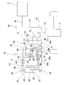
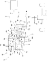
- FIG. 1 is a schematic cross-sectional view of a drive system incorporating the two-speed transmission of the first example of the embodiment of the present invention.
- FIG. 2A is a schematic cross-sectional view showing a torque transmission path in the reduced speed ratio mode of the two-speed transmission of the first example
- FIG. 2B is a two-speed transmission of the first example. It is a schematic cross-sectional view which shows the torque transmission path in the high reduction ratio mode of.
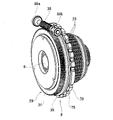
- FIG. 3 is a perspective view of the two-speed transmission of the first example.
- FIG. 4 is a cross-sectional view of the two-speed transmission of the first example.
- FIG. 5 is a perspective view showing the planetary gear mechanism of the two-speed transmission of the first example with the planetary gear mechanism removed.
- FIG. 5 is a perspective view showing the planetary gear mechanism of the two-speed transmission of the first example with the planetary gear mechanism removed.
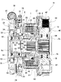
- FIG. 6 is a cross-sectional view of the two-speed transmission shown in FIG.
- FIG. 7 is an exploded perspective view of the two-speed transmission shown in FIG.
- FIG. 8 is a perspective view showing a state before combining the worm of the two-speed transmission of the first example and the pair of support bearings.
- FIG. 9 is an exploded perspective view of the first engaging device of the two-speed transmission of the first example.
- FIG. 10 is an enlarged view of part X of FIG.
- FIG. 11 is a perspective view of the drive cam of the two-speed transmission of the first example.
- FIG. 12 is an exploded perspective view of the driven cam and the rolling element of the two-speed transmission of the first example.
- FIG. 13 (a) is a perspective view of the flange portion and the pressing member constituting the rotating member of the two-speed transmission of the first example
- FIG. 13 (b) is an exploded perspective view of the flange portion and the pressing member.
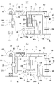
- FIG. 14 is a schematic cross-sectional view of a drive system incorporating the two-speed transmission of the second example of the embodiment of the present invention
- FIG. 15 is a schematic cross-sectional view of a drive system incorporating the two-speed transmission of the third example of the embodiment of the present invention.
- FIG. 16A is a schematic cross-sectional view showing a torque transmission path in the reduced speed ratio mode of the two-speed transmission of the third example
- FIG. 16B is a two-stage braiding machine of the third example.
- FIG. 17 is a schematic cross-sectional view of a drive system incorporating the two-speed transmission of the fourth example of the embodiment of the present invention.
- FIG. 18A is a schematic cross-sectional view showing a torque transmission path in the reduced speed ratio mode of the second-speed transmission of the fourth example
- FIG. 18B is a two-speed transmission of the fourth example.
- FIG. 19 is a cross-sectional view of the two-speed transmission of the fourth example.
- FIG. 20 is a schematic cross-sectional view of a drive system incorporating the two-speed transmission of the fifth example of the embodiment of the present invention.
- FIG. 21 (a) is a schematic cross-sectional view showing a torque transmission path in the reduced speed ratio mode of the second-speed transmission of the fifth example
- FIG. 21 (b) is a two-speed transmission of the fifth example. It is a schematic cross-sectional view which shows the torque transmission path in the high reduction ratio mode of.
- FIG. 22 is a schematic cross-sectional view of a drive system incorporating the two-speed transmission of the sixth example of the embodiment of the present invention.
- FIG. 23 is a schematic cross-sectional view of a drive system incorporating the two-speed transmission of the seventh example of the embodiment of the present invention.
- FIG. 21 (a) is a schematic cross-sectional view showing a torque transmission path in the reduced speed ratio mode of the second-speed transmission of the fifth example
- FIG. 21 (b) is a two-speed transmission of the fifth example.
- FIG. 24 (a) is a schematic cross-sectional view showing a torque transmission path in the reduced speed ratio mode of the two-speed transmission of the seventh example
- FIG. 24 (b) is a two-speed transmission of the seventh example. It is a schematic cross-sectional view which shows the torque transmission path in the high reduction ratio mode of.
- FIG. 25 is a diagram for explaining the effect of incorporating a transmission into a drive device using an electric motor as a drive source.
- the two-speed transmission 1 of this example is arranged between a drive source 2 such as an electric motor or an engine and a differential device 3, and increases (decelerates) or increases the output torque of the drive source 2. It is transmitted to the differential device 3 as it is without doing so.
- the two-speed transmission 1 includes an input member 4, an output member 5, a rotating member 6, a first engaging device 7, a second engaging device 8, an elastic urging means 9, and a pressing device 10. It includes a first bearing 11, a second bearing 12, and a planetary deceleration mechanism 13.
- the input member 4 is configured by a housing or the like that accommodates the two-speed transmission 1, and is rotatably supported by a rolling bearing or the like (not shown) with respect to a fixed portion 14 that does not rotate even during use.
- the input member 4 is formed in a tubular shape (hollow).
- the input member 4 has an input gear 17 that meshes with a drive gear 16 provided on the output shaft 15 of the drive source 2 at an end on one side in the axial direction (right side in FIG. 1). That is, the input member 4 can be rotationally driven by the drive source 2.
- the output member 5 is coaxially supported with the input member 4 and can rotate relative to the input member 4.
- the output member 5 is supported radially inside the cylindrical input member 4 via a rolling bearing (not shown) or the like so as to be able to rotate relative to the input member 4.
- the output member 5 has an output gear 18 at one end in the axial direction.
- the output gear 18 meshes with a gear provided in the input portion of the differential device 3. That is, the output member 5 is connected to the input portion of the differential device 3 so as to be able to transmit torque.
- the rotating member 6 is coaxially supported with the input member 4 and the output member 5 and can rotate relative to the input member 4 and the output member 5.
- the rotating member 6 is rotatably supported with respect to the fixed portion 14 via a second engaging device 8 described later, a pressing device 10, and a second bearing 12.
- the rotating member 6 has a small-diameter flange portion 19 protruding outward in the radial direction in the intermediate portion in the axial direction, and is on the other side in the axial direction (left side in FIG. 1) with respect to the small-diameter flange portion 19.
- the located portion has a flange portion 20 protruding outward in the radial direction.
- the flange portion 20 has a hollow circular plate shape, and has a first circular ring portion 21 having a partially arcuate through hole 64 for inserting a pressing member 41 described later at a plurality of radial intermediate portions, and a first circle.
- the first cylindrical portion 22 bent toward the other side in the axial direction from the radially outer end of the ring portion 21, and the hollow bent toward the outer side in the radial direction from the other end in the axial direction of the first cylindrical portion 22. It has a circular plate-shaped second annular portion 23 and a second cylindrical portion 24 bent from the radially outer end of the second annular portion 23 toward the other side in the axial direction.
- the rotating member 6 having the flange portion 20 is configured by externally fitting and fixing the stepped cylindrical member 70 as shown on the left side of FIG. 13B to the shaft member 69 having the small diameter flange portion 19. are doing. That is, the stepped cylindrical member 70 has a hollow circular plate shape, and has a first circular ring portion 21 having a through hole 64, a first cylindrical portion 22, a second circular ring portion 23, and a second cylindrical portion 24. It also has a small-diameter cylindrical portion 74 bent from the radially inner end of the first circular ring portion 21 toward the other side in the axial direction.
- the female spline portion 71 provided on the inner peripheral surface of the small-diameter cylindrical portion 74 of the rotating member 6 is spline-engaged with the male spline portion provided on the outer peripheral surface of the shaft member 69.
- the first engaging device 7 has a plurality of first friction plates 25 and a plurality of second friction plates 26 supported so as to be relatively displaced in the axial direction, and includes an input member 4 and a rotating member 6. It is prepared in between. That is, the first engaging device 7 is composed of a multi-plate clutch in which the first friction plate 25 supported by the input member 4 and the second friction plate 26 supported by the rotating member 6 are alternately superposed. Has been done. In the first engaging device 7, the first friction plate 25 and the second friction plate 26 are pressed against each other and connected to each other, and the input member 4 and the rotating member 6 rotate together and the first friction. The plate 25 and the second friction plate 26 are cut by releasing the force of pressing each other, and the input member 4 and the rotating member 6 can be switched to a state of relative rotation.
- the first friction plate 25 is supported by the inner peripheral surface of the end portion on the other side in the axial direction of the input member 4 so as to be displaced in the axial direction.
- the second friction plate 26 located on the other side in the axial direction is supported by the outer peripheral surface of the first cylindrical portion 22 of the rotating member 6 so as not to be displaced in the axial direction.
- the 2 friction plate 26 is supported on the outer peripheral surface of the first cylindrical portion 22 so as to be displaced in the axial direction.
- the second engaging device 8 is provided between the fixed portion 14 and the rotating member 6, and switches between a state in which the rotating member 6 can rotate and a state in which the rotating member 6 cannot rotate with respect to the fixed portion 14.
- the second engaging device 8 is provided between the inner peripheral surface of the fixed portion 14 and the second cylindrical portion 24 of the rotating member 6.
- the second engaging device 8 can be configured by, for example, a meshing type or friction type clutch (braking device) whose disconnection / contact state can be switched by an actuator.
- the actuator for switching the engagement / disengagement state of the clutch is not particularly limited, and a hydraulic actuator, an electromagnetic actuator, or the like can be used.
- the second engaging device 8 is disconnected in the reduced speed ratio mode in which the first engaging device 7 is connected, and is connected in the high reduction ratio mode in which the first engaging device 7 is disconnected.
- the second engaging device 8 includes an outer diameter side cylindrical member 75, an inner diameter side cylindrical member 76, and at least one engaging pin (not shown).
- a select plate 77 is provided.
- the outer diameter side cylindrical member 75 has an outer peripheral side uneven portion 78 on the outer peripheral surface in which concave portions and convex portions are alternately arranged in the circumferential direction.
- the outer diameter side cylindrical member 75 is supported by the fixed portion 14 so as to be non-relatively rotatable by engaging the outer peripheral side uneven portion 78 with the inner peripheral side uneven portion provided on the inner peripheral surface of the fixed portion 14. There is.
- the inner diameter side cylindrical member 76 is externally fitted and fixed to the second cylindrical portion 24 of the rotating member 6 so as not to be relatively rotatable.
- the engagement pin is disengaged and disengaged between the outer diameter side cylindrical member 75 and the inner diameter side cylindrical member 76.
- the engaging pin projects from the inner peripheral surface of the outer diameter side cylindrical member 75 inward in the radial direction and is imparted with elasticity toward the inward in the radial direction with respect to the outer diameter side cylindrical member 75. It is supported in a state of being.
- the inner diameter side cylindrical member 76 has an engaging recess on the outer peripheral surface on which the tip of the engaging pin can be engaged.
- the select plate 77 has a mode select portion which is a concave-convex portion in the circumferential direction, and is provided so as to be rotatable and driveable by an electric motor 30 described later via a drive cam 31.
- the second engaging device 8 switches between a state in which the outer diameter side cylindrical member 75 and the inner diameter side cylindrical member 76 are relatively rotatable and a relative non-rotatable state based on the rotation of the select plate 77. That is, based on the rotation of the select plate 77, the engaging pin is pushed upward in the radial direction by the convex portion constituting the mode select portion, thereby disengaging the engaging pin from the engaging concave portion. As a result, the rotation of the inner diameter side cylindrical member 76 with respect to the outer diameter side cylindrical member 75 is allowed, and the rotation of the rotating member 6 with respect to the fixed portion 14 is allowed.
- the elastic urging means 9 is provided between the rotating member 6 and the first engaging device 7, and elastically urges the first friction plate 25 and the second friction plate 26 in a direction of pressing against each other.
- the elastic urging means 9 has a pressing plate 27 and an elastic member 28.
- the pressing plate 27 is formed in the shape of a hollow circular plate, and is around the portion between the small diameter flange portion 19 and the flange portion 20 in the axial direction of the rotating member 6, in the axial direction with respect to the rotating member 6. It is supported to allow displacement. Further, in the pressing plate 27, the end surface of the radial outer portion on the other side in the axial direction faces the one side surface in the axial direction of the second friction plate 26 located on one side in the axial direction of the second friction plate 26. ..
- the elastic member 28 is sandwiched between the other side surface of the small diameter flange portion 19 of the rotating member 6 in the axial direction and one side surface in the axial direction of the pressing plate 27 in an elastically compressed state. That is, the elastic urging means 9 presses the second friction plate 26 on one side in the axial direction toward the other side in the axial direction through the pressing plate 27 by the force that the elastic member 28 tries to elastically restore. As a result, the first friction plate 25 and the second friction plate 26 are elastically urged in the direction of pressing against each other.
- the elastic member 28 can be formed of a disc spring, a torsion coil spring, or the like.
- the pressing device 10 is provided between the fixed portion 14 and the rotating member 6, and presses the elastic urging means 9 in a direction of releasing the force of pressing the first friction plate 25 and the second friction plate 26 against each other. ..
- the pressing device 10 has a cam device 29 and an electric motor 30.
- the cam device 29 has a drive cam 31, a driven cam 32, and a plurality of rolling elements 33.
- a roller is used as the rolling element 33, and the rolling element 33 faces the driven cam 32 in the radial direction centered on the central axis of the driven cam 32. It freely supports the rotation (rotation) around the rotating axis C.
- FIGS. 1 to 2 (b) schematically show the cam device 29 in order to facilitate understanding of the invention.
- the drive cam 31 has a drive cam surface 34 in which the same number of concave portions and convex portions are alternately arranged in the circumferential direction in the radial inner portion of one side surface in the axial direction.
- a wheel tooth 35 which is a helical gear, is provided on the outer peripheral surface.
- the drive cam 31 is supported by an angular contact ball bearing 91, a cylindrical member 84, and a second bearing 12, which will be described later, so as to be able to rotate relative to the rotating member 6 with respect to the rotating member 6.
- the drive cam 31 has pin portions 90 protruding toward one side in the axial direction at a plurality of circumferential directions (three locations in the illustrated example) in the radial intermediate portion on one side surface in the axial direction.
- the tip portion of the pin portion 90 is engaged (rattling inner fitting) with the engaging hole provided in the select plate 77.
- the drive cam 31 and the select plate 77 rotate integrally (in the same direction and at the same speed).
- the driven cam 32 is configured in the shape of a hollow circular plate, and has rectangular holes 79 penetrating in the axial direction at a plurality of circumferential directions (three in the illustrated example) in the radial intermediate portion. It also has substantially semicircular plate-shaped support plate portions 80a and 80b protruding from both radial side portions of the rectangular hole 79 toward one side in the axial direction.
- Each of the radial outer support plate portions 80a is provided with a support hole 81 which is a circular hole penetrating in the radial direction, and each of the radial inner support plate portions 80b has a circular opening on the radial outer surface.
- the support recess 82 is provided.
- the driven cam 32 is arranged around the rotating member 6 so as to be displaced only in the axial direction.
- the driven cam 32 has a female spline portion 83 provided on the inner peripheral surface and a spline portion 85 provided on the outer peripheral surface of the tubular member 84 supported and fixed to the fixed portion 14. By matching, the axial displacement is supported with respect to the fixed portion 14.
- Each of the plurality of rolling elements 33 has a cylindrical shape, and is freely rotated with respect to the support plate portions 80a and 80b via the cylindrical support shaft 86 and the plurality of rollers 87. .. That is, one end of the support shaft 86 in the axial direction (the outer end in the radial direction about the central axis of the driven cam 32) is internally fitted and fixed in the support hole 81 of the support plate portion 80a on the outer side in the radial direction. Further, the end portion on the other side in the axial direction of the support shaft 86 (the inner end portion in the radial direction about the central axis of the driven cam 32) is provided in the support recess 82 of the support plate portion 80b on the inner diameter direction. Inner fitting is fixed.
- the plurality of rollers 87 are rotatably sandwiched between the inner peripheral surface of the rolling element 33 and the outer peripheral surface of the axial intermediate portion of the support shaft 86.
- the rolling element 33 is freely supported by the driven cam 32 in rotation (rotation) about the rotation axis C facing the radial direction about the central axis of the driven cam 32.
- each outer peripheral surface of the rolling element 33 is rolled into contact with the drive cam surface 34 provided on one side surface in the axial direction of the drive cam 31 on the other side in the axial direction of the driven cam 32.
- the rolling element 33 can be composed of balls.
- the same number of concave portions and convex portions are alternately arranged in the circumferential direction on the other side surface in the axial direction of the driven cam 32. Form a drive cam surface.
- the worm 38 connected to the output shaft of the electric motor 30 is meshed with the wheel teeth 35 provided on the outer peripheral surface of the drive cam 31.
- the drive cam 31 can be rotationally driven by the electric motor 30.
- the worm 38 is rotatably supported with respect to the fixed portion 14 by a pair of support bearings 88a and 88b.
- the screw-shaped worm 38 and the wheel tooth 35 which is a helical gear, are meshed with each other, but the spur gear or the captive gear provided on the output shaft of the electric motor and the drive cam are provided.
- the drive cam can be rotationally driven by the electric motor by engaging a spur gear or a bevel gear, or by passing a belt or a chain between the output shaft of the electric motor and the drive cam.
- the first bearing 11 is provided between the elastic urging means 9 and the pressing device 10.
- the first bearing 11 has a pair of raceway wheels 39a and 39b, and a plurality of rolling elements 40 rotatably arranged between them. More specifically, the first bearing 11 is provided between the tubular pressing member 41 connected to the pressing plate 27 of the elastic urging means 9 and the driven cam 32 of the pressing device 10.
- the pressing member 41 is provided from a cylindrical base 72 and a plurality of circumferential ends (three in the illustrated example) of one end of the base 72 in the axial direction to one side in the axial direction. It has a partial cylindrical portion 73 protruding toward.
- the raceway ring 39a on one side in the axial direction is supported and fixed to the end on the other side in the axial direction of the base 72, and the tip end portion (end on one side in the axial direction) of the partial cylindrical portion 73 is pressed by the pressing plate 27. It faces the radial middle part of the other side surface in the axial direction.
- the first bearing 11 is composed of a single thrust ball bearing using a ball as the rolling element 40.
- a thrust rolling bearing such as a thrust angular contact ball bearing, a thrust needle bearing, a thrust roller bearing, or a thrust tapered roller bearing may be used.
- the thrust bearing applied to the first bearing 11 may be composed of a bearing unit in which a plurality of bearings are combined.
- the second bearing 12 is provided between the rotating member 6 and the pressing device 10.
- a second bearing 12, a cylindrical member 84, and an angular contact ball bearing 91 are provided between the rotating member 6 and the drive cam 31 of the pressing device 10.
- the second bearing 12 is composed of a double row ball bearing, and includes an inner ring 43 that is externally fitted and fixed to the rotating member 6, an outer ring 44 that is internally fitted and fixed to the tubular member 84, and an inner ring 43 and an outer ring 44. It has a plurality of rolling elements 45 arranged so as to be rollable between them.
- a plurality of angular contact ball bearings 91 are rotatably arranged between the inner ring 92 fitted and fixed to the tubular member 84, the outer ring 93 fitted and fixed to the drive cam 31, and the inner ring 92 and the outer ring 93. It has a rolling element 94 and the like. In FIG. 1, the cylindrical member 84 and the angular contact ball bearing 91 are omitted.
- the second bearing 12 is composed of a single row deep groove ball bearing using a ball as the rolling element 45.
- the configuration of the second bearing 12 is not particularly limited as long as it enables relative rotation between the rotating member and the pressing device and can support the axial urging force by the elastic urging means. ..
- a radial rolling bearing capable of bearing a thrust load such as a deep groove ball bearing, a radial angular contact ball bearing, and a radial tapered roller bearing can be used as the second bearing 12.
- a thrust rolling bearing such as a thrust ball bearing, a thrust needle bearing, a thrust roller bearing, a thrust tapered roller bearing, and a thrust angular contact ball bearing can also be used.
- the second bearing 12 can be configured by a bearing unit in which a plurality of bearings are combined.
- a member for example, a drive cam constituting a pressing device is supported and fixed to one of the raceway rings (for example, an outer ring) of a pair of raceway rings constituting the second bearing, and the present invention is carried out.
- a rotating member can also be supported and fixed to the other raceway ring (for example, an inner ring).
- the planetary deceleration mechanism 13 has a sun gear 46 which is a sun element, a ring gear 47 which is a ring element, a carrier 48 which is a carrier element, and a plurality of planetary gears 49, each of which is a planetary element. That is, in this example, the planetary deceleration mechanism 13 is configured by a single pinion type planetary gear mechanism.
- the sun gear 46 is connected to the rotating member 6 so as to be able to transmit torque.
- the sun gear 46 is provided at one end of the rotating member 6 in the axial direction.
- the ring gear 47 is arranged coaxially with the sun gear 46 around the sun gear 46, and is connected to the input member 4 so as to be able to transmit torque.
- the ring gear 47 is provided in the axial intermediate portion of the input member 4.
- the carrier 48 is arranged coaxially with the sun gear 46 and the ring gear 47 between the sun gear 46 and the ring gear 47 in the radial direction, and is connected to the output member 5 so as to be able to transmit torque.
- Each of the plurality of planetary gears 49 meshes with the sun gear 46 and the ring gear 47, and is supported by the carrier 48 so as to be able to rotate (rotate) about its own central axis.
- the two-speed transmission 1 of this example is provided between the first bearing 11 and the rotating member 6, and further includes a preload applying means 89 for applying a preload in the axial direction to the first bearing 11 which is a thrust bearing.
- the preload applying means 89 has, among the pair of raceway rings 39a and 39b constituting the first bearing 11, the axial one side surface of the raceway ring 39a on one side in the axial direction and the flange portion 20 constituting the rotating member 6. It is sandwiched between the first circular ring portion 21 and the other side surface in the axial direction in an elastically compressed state.
- FIG. 2B a preload is applied to the first bearing 11 even when the pressing plate 27 is pressed toward one side in the axial direction against the elasticity of the elastic member 28.
- the first bearing 11 is prevented from falling off from between the elastic urging means 9 and the pressing device 10.
- the reduction ratio between the input member 4 and the output member 5 is increased by switching between the disconnected state of the first engaging device 7 and the disconnected state of the second engaging device 8. It is possible to switch between a small reduction speed ratio mode (reduction ratio is 1) and a high reduction ratio mode in which the reduction ratio is larger than that of the reduction speed ratio mode.
- reduction ratio is 1
- high reduction ratio mode in which the reduction ratio is larger than that of the reduction speed ratio mode.
- the electric motor 30 rotationally drives the drive cam 31 in a direction in which the amount of the rolling element 33 riding from the bottom of the recess constituting the drive cam surface 34 decreases. ..
- the driven cam 32 releases the force for pressing the pressing plate 27 toward one side in the axial direction via the first bearing 11 and the pressing member 41.
- the elastic restoring force of the elastic member 28 causes the pressing plate 27, the first bearing 11, and the pressing member 41 to move toward the other side in the axial direction.
- the second friction plate 26 on one side in the axial direction is pressed toward the other side in the axial direction by the pressing plate 27.
- the first friction plate 25 and the second friction plate 26 are pressed against each other, the first engagement device 7 is connected, and the input member 4 and the rotating member 6 rotate integrally. Therefore, the sun gear 46 and the ring gear 47 rotate integrally.
- the electric motor 30 rotationally drives the drive cam 31 in a direction in which the amount of the rolling element 33 riding from the bottom of the recess constituting the drive cam surface 34 increases. ..
- the driven cam 32 presses the pressing plate 27 toward one side in the axial direction via the first bearing 11 and the pressing member 41, elastically shrinking the axial dimension of the elastic member 28, and the first.
- the force that the friction plate 25 and the second friction plate 26 press against each other is released.
- the distance between the first friction plate 25 and the second friction plate 26 is widened, so that the first engaging device 7 is cut off and the input member 4 and the rotating member 6 can rotate relative to each other. Therefore, the sun gear 46 and the ring gear 47 can rotate relative to each other.
- the rotational torque of the input member 4 is based on the path shown by the thick line in FIG. 2B, that is, the rotation motion of the input member 4, the ring gear 47, the planetary gear 49, and the meshing with the sun gear 46. It is transmitted to the output member 5 by the revolving motion of the planetary gear 49 and the path passing through the carrier 48.
- the rotational torque of the input member 4 is increased by the planetary deceleration mechanism 13 and transmitted to the output member 5.
- the reduction ratio between the input member 4 and the output member 5 in the high reduction ratio mode is determined by the gear ratio between the ring gear 47 and the sun gear 46 (the number of teeth of the ring gear 47 / the number of teeth of the sun gear 46).
- the two-speed transmission 1 of this example switches the reduction ratio between the input member 4 and the output member 5 by switching between the disconnection state of the first engagement device 7 and the disconnection state of the second engagement device 8. It can be switched between high and low. Specifically, in the region where the rotational torque input to the input member 4 is low speed and high torque, the two-speed transmission 1 is switched to the high reduction ratio mode, and the rotational torque input to the input member 4 is high speed and low torque. In the region of, the two-speed transmission 1 is switched to the reduced speed ratio mode. Therefore, the acceleration performance and high-speed performance when the electric vehicle or the hybrid vehicle is traveling only with the electric motor as the drive source are shown in the left side portion of the solid line a in FIG. 25 from the point P and in the chain line b. It has a characteristic that the portion on the right side of the point P is continuous, and can be similar to the gasoline engine vehicle shown by the broken line c in FIG. 25.
- the torque transmission efficiency can be ensured satisfactorily. The reason for this will be described below.
- a state in which the pressing device 10 generates a pressing force that is, a state in which the pressing plate 27 is pressed toward one side in the axial direction by the driven cam 32 via the first bearing 11 and the pressing member 41 (FIG. 2B).
- a force directed to one side in the axial direction is applied to the first bearing 11.
- the reaction force associated with pressing the pressing plate 27 toward one side in the axial direction by the driven cam 32 is directed toward the other side in the axial direction by the second bearing 12 via the rolling element 33 and the driving cam 31.
- the raceway ring 39a on one side in the axial direction constituting the first bearing 11 is supported by the rotating member 6 via the pressing member 41 and the pressing plate 27, and the raceway ring 39b on the other side in the axial direction is supported by the cam device 29. It is supported by the fixed portion 14 via the angular contact ball bearing 91 and the tubular member 84. Further, the inner ring 43 constituting the second bearing 12 is externally fitted and fixed to the rotating member 6, and the outer ring 44 is attached to the drive cam 31 of the cam device 29 via the tubular member 84 and the angular contact ball bearing 91. It is supported.
- the two-speed transmission 1 of this example in a state where the pressing device 10 generates a pressing force, that is, the pressing plate 27 is pressed toward one side in the axial direction, the axial dimension of the elastic member 28 is elastically contracted, and the first In a state where the force of pressing the friction plate 25 and the second friction plate 26 against each other is released and the first engaging device 7 is disconnected, the second engaging device 8 is connected. In the high reduction ratio mode in which the first engaging device 7 is disconnected and the second engaging device 8 is connected, the relative rotation of the rotating member 6 with respect to the fixed portion 14 is prevented.
- the pressing force generated by the pressing device 10 is applied to the rotating member 6 in one axial direction from the driven cam 32 via the pressing member 41, the first bearing 11, the pressing plate 27, and the elastic member 28.
- the reaction force accompanying the generation of the pressing force by the pressing device 10 is applied from the drive cam 31 to the rotating member 6 via the second bearing 12 in the other direction in the axial direction. In this way, the axial forces associated with the pressing device 10 generating the pressing force cancel (cancel) each other in the rotating member 6.
- the first engaging device 7 is connected.
- the pressing device 10 does not generate pressing pressure.
- the first bearing 11 and the second bearing 12 are not subjected to the axial force (left-right direction in FIG. 2A) due to the pressing device 10 generating the pressing force, so that the first bearing is the first bearing.
- the rolling resistance of the 11 and the second bearing 12 is not excessive, and therefore the torque loss is not excessive.
- a roller is used as the rolling element 33, and the rolling element 33 is centered on the rotation axis C facing the radial direction about the central axis of the driven cam 32 with respect to the driven cam 32. It freely supports the rotation (rotation). Therefore, the driven cam 32 can be reliably displaced in the axial direction based on the rotation of the drive cam 31. That is, when a ball is used as the rolling element constituting the cam device, when the driving cam is rotated, the surface of the rolling element and the rolling contact portion between the driving cam surface and / or the driven cam surface cause slippage. there is a possibility.
- the driven cam cannot be displaced in the axial direction, or the driven cam cannot be displaced with respect to the rotation amount of the drive cam. It may not be possible to secure a sufficient amount of axial displacement.
- the second engaging device 8 a clutch capable of switching the disengagement state by an actuator is adopted, but in the case of carrying out the present invention, the second engaging device is a reduction in which the first engaging device is connected.
- the clutch is not particularly limited, and a clutch having various structures known conventionally can be adopted.
- the second engaging device may be configured by a one-way clutch including a freewheel.
- the second engaging device allows the rotating member to rotate in the same direction as the rotation direction of the input member when the vehicle moves forward.
- it is configured to prevent the rotating member from trying to rotate in the direction opposite to the rotation direction of the input member when the vehicle is moving forward.
- the pressing device 10 includes a cam device 29 in which a rolling element 33 is sandwiched between a driving cam 31 and a driven cam 32, and an electric motor 30, but when the present invention is carried out, the pressing device is a pressing device.
- the elastic urging means can be pressed in a direction in which the force of pressing the first friction plate and the second friction plate against each other is released, the pressing device having various structures can be adopted without particular limitation. ..
- a pressing device a cam device in which a drive cam surface provided on the drive cam and a driven cam surface provided on the driven cam are directly engaged (sliding), extend in the circumferential direction to the outer peripheral surface.
- a cam device having a driven cam having a guide groove that changes in the axial direction and a drive cam having an engaging protrusion that allows displacement along the guide groove can be used as the pressing device.
- a single pinion type planetary gear mechanism is adopted as the planetary deceleration mechanism 13, but when the present invention is carried out, a double pinion type planetary gear mechanism can also be adopted as the planetary deceleration mechanism.
- a planetary deceleration mechanism is provided between the sun roller, a ring roller arranged around the sun roller, and a rolling surface which is arranged between the sun roller and the ring roller in the radial direction and is an outer peripheral surface. It can also be configured by a friction roller mechanism having a planetary roller frictionally engaged with the outer peripheral surface of the sun roller and the inner peripheral surface of the ring roller.
- the hollow output member 5a is supported around the solidly configured input member 4a so as to be relatively rotatable with respect to the input member 4a, and the hollow rotating member 6a is formed. Around the output member 5a, relative rotation with respect to the output member 5a is possible.
- the input member 4a is integrally configured with the output shaft of the drive source 2.
- the output member 5a is connected to the input portion of the differential device 3 so as to be able to transmit torque via the intermediate transmission shaft 50. That is, the output gear 18 provided on the output member 5a is meshed with the large-diameter gear 51 provided on the intermediate transmission shaft 50, and the small-diameter gear 52 provided on the intermediate transmission shaft 50 is used in the differential device 3. It is meshed with a gear provided in the input section.
- the axial direction of the two-speed transmission 1 is opposite to the axial direction of the two-speed transmission 1 of the first example shown in FIG. 1 (inverted left and right). .. Also in this example, the axial forces associated with the pressing device 10 generating the pressing force cancel (cancel) within the rotating member 6a and / or the fixed portion 14.
- the composition and action of other parts are the same as in the first example.
- FIGS. 15 to 16 A third example of the embodiment of the present invention will be described with reference to FIGS. 15 to 16 (b).
- the sun gear 46 is connected to the input member 4b to enable torque transmission
- the ring gear 47 is connected to the rotating member 6b to enable torque transmission
- the carrier 48 is an output member. It is connected to 5b so that torque can be transmitted.
- the rotating member 6b has a small-diameter flange portion 19a protruding inward in the radial direction at the intermediate portion in the axial direction, and has an end portion on the other side in the axial direction (left side in FIG. 15) toward the inward in the radial direction. It has a protruding flange portion 20a.
- the flange portion 20a includes a hollow circular plate-shaped first annular portion 21a, a first cylindrical portion 22a bent from the radially inner end of the first annular portion 21a toward the other side in the axial direction, and a first cylinder portion 20a.
- a hollow circular plate-shaped second annular portion 23a bent inward in the radial direction from the other end in the axial direction of the cylindrical portion 22a, and an axially other portion from the inner end in the radial direction of the second annular portion 23a. It has a second cylindrical portion 24a that is bent toward the side.
- the plurality of first friction plates 25 constituting the first engaging device 7 are supported by the outer peripheral surface of the end portion on the other side in the axial direction of the input member 4b so as to be displaced in the axial direction.
- the second friction plate 26 located on the other side in the axial direction is supported by the inner peripheral surface of the first cylindrical portion 22a of the rotating member 6b so as not to be displaced in the axial direction.
- the other second friction plate 26 is supported by the inner peripheral surface of the first cylindrical portion 22a so as to be displaced in the axial direction.
- the second engaging device 8 is provided between the inner peripheral surface of the fixed portion 14 and the second cylindrical portion 24a of the rotating member 6b.
- the pressing device 10a includes a cylinder device 53 and a direction switching valve 54.
- the cylinder device 53 is configured by fitting the piston 56 to the cylinder 55, and has a pair of hydraulic chambers 57a and 57b provided with the piston 56 interposed therebetween in the cylinder 55.
- a first bearing 11 and a pressing member 41 are provided between the piston 56 and the pressing plate 27 of the elastic urging means 9.
- the direction switching valve 54 connects one of the pair of hydraulic chambers 57a and 57b to the hydraulic source 59 to raise the hydraulic pressure based on the energization of the solenoid 58, and oils the other hydraulic chamber. It switches between the state of connecting to the reservoir 60 to release the hydraulic pressure and the reverse state.
- the direction switching valve 54 is operated by energizing the solenoid 58 to operate the hydraulic chamber on one side in the axial direction.
- 57a is connected to the hydraulic pressure source 59 to increase the hydraulic pressure
- the hydraulic chamber 57b on the other side in the axial direction is connected to the oil reservoir 60 to release the hydraulic pressure.
- the piston 56 releases the force for pressing the pressing plate 27 toward one side in the axial direction via the first bearing 11 and the pressing member 41.
- the elastic restoring force of the elastic member 28 causes the pressing plate 27, the first bearing 11, and the pressing member 41 to move toward the other side in the axial direction.
- the second friction plate 26 on one side in the axial direction is pressed toward the other side in the axial direction by the pressing plate 27.
- the first friction plate 25 and the second friction plate 26 are pressed against each other, the first engagement device 7 is connected, and the input member 4b and the rotating member 6b rotate integrally. Therefore, the sun gear 46 and the ring gear 47 rotate integrally.
- the direction switching valve 54 is operated by energizing the solenoid 58 to operate the hydraulic chamber on one side in the axial direction.
- the 57a is connected to the oil reservoir 60 to release the hydraulic pressure
- the hydraulic chamber 57b on the other side in the axial direction is connected to the hydraulic pressure source 59 to increase the hydraulic pressure.
- the piston 56 presses the pressing plate 27 toward one side in the axial direction via the first bearing 11 and the pressing member 41, elastically shrinks the axial dimension of the elastic member 28, and causes the first friction.
- the force that the plate 25 and the second friction plate 26 press against each other is released.
- the rotational torque of the input member 4b is based on the path shown by the thick line in FIG. 16B, that is, the rotation motion of the input member 4b, the sun gear 46, the planetary gear 49, and the meshing with the ring gear 47. It is transmitted to the output member 5b by the revolving motion of the planetary gear 49 and the path passing through the carrier 48. That is, in the high reduction ratio mode, the rotational torque of the input member 4b is increased by the planetary reduction mechanism 13 and transmitted to the output member 5b.
- the first is in a state where the rolling resistance is increased due to the axial force applied by the pressing device 10a generating the pressing force, except for a short time during the mode switching.
- the bearing 11 and the second bearing 12 do not rotate. Therefore, it is possible to prevent the occurrence of excessive torque loss in the first bearing 11 and the second bearing 12, and it is possible to satisfactorily secure the torque transmission efficiency of the two-speed transmission 1a.
- the composition and action of other parts are the same as in the first example.
- FIGS. 17 to 19 A fourth example of the embodiment of the present invention will be described with reference to FIGS. 17 to 19.
- the sun gear 46 is connected to the input member 4c to enable torque transmission
- the ring gear 47 is connected to the rotating member 6c to enable torque transmission
- the carrier 48 is an output member. It is connected to 5c so that torque can be transmitted.
- the input member 4c has an input gear 17 at the end on one side in the axial direction (right side in FIG. 17).
- the sun gear 46 is provided in the axial intermediate portion of the input member 4c.
- the input member 4c has a flange portion 61 bent radially outward from a portion on the other side in the axial direction (left portion in FIG. 17) with respect to the portion provided with the sun gear 46, and an end portion on the radial outer side of the flange portion 61. It has a cylindrical portion 62 that is bent toward the other side in the axial direction.
- the plurality of first friction plates 25 constituting the first engaging device 7 are supported so as to be axially displaced by the inner peripheral surface of the end portion of the cylindrical portion 62 on the other side in the axial direction.
- the rotating member 6c has a small-diameter flange portion 19b protruding outward in the radial direction at one end in the axial direction, and a flange portion 20b protruding outward in the radial direction in the middle portion in the axial direction. ..
- the flange portion 20b includes a hollow circular plate-shaped first annular portion 21, a first cylindrical portion 22 bent from the radially outer end portion of the first annular portion 21 toward the other side in the axial direction, and a first cylinder portion 22.
- a hollow circular plate-shaped second annular portion 23 bent outward in the radial direction from the other end of the cylindrical portion 22 in the axial direction, and an intermediate portion in the radial direction of the second annular portion 23 to the other side in the axial direction. It has a second cylindrical portion 24 that is bent toward it, and a third cylindrical portion 63 that is bent toward one side in the axial direction from the radially outer end of the second annular portion 23.
- the ring gear 47 is provided at one end of the third cylindrical portion 63 in the axial direction.
- ⁇ Reduced speed ratio mode> In order to switch the two-speed transmission 1b of this example to the reduced speed ratio mode, as shown in FIG. 18A, the input member 4c and the rotating member 6c are integrated by connecting the first engaging device 7. The sun gear 46 and the ring gear 47 are made to rotate integrally. Further, by cutting the second engaging device 8, the relative rotation of the rotating member 6c with respect to the fixed portion 14 is allowed, and the rotation of the ring gear 47 with respect to the fixed portion 14 is allowed.
- the rotational torque of the input member 4c is based on the path shown by the thick line in FIG. 18B, that is, the rotation motion of the input member 4c, the sun gear 46, the planetary gear 49, and the meshing with the ring gear 47. It is transmitted to the output member 5c by the revolving motion of the planetary gear 49 and the path passing through the carrier 48. That is, in the high reduction ratio mode, the rotational torque of the input member 4c is increased by the planetary deceleration mechanism 13 and transmitted to the output member 5c.
- the first is in a state where the rolling resistance is increased due to the axial force applied by the pressing device 10 generating the pressing force, except for a short time during the mode switching.
- the bearing 11 and the second bearing 12 do not rotate. Therefore, it is possible to prevent the occurrence of excessive torque loss in the first bearing 11 and the second bearing 12, and it is possible to satisfactorily secure the torque transmission efficiency of the two-speed transmission 1b.
- the composition and action of other parts are the same as in the first example.
- the planetary reduction mechanism 13a includes a sun gear 46 which is a sun element, a ring gear 47 which is a ring element, a carrier 48 which is a carrier element, and a plurality of first planetary gears 49a, each of which is a first planetary element. And each has a second planetary gear 49b, which is a second planetary element. That is, in this example, the planetary deceleration mechanism 13a is configured by a double pinion type planetary gear mechanism.
- a plurality of first planetary gears 49a and second planetary gears 49b are engaged with each other as a set of one first planetary gear 49a and one second planetary gear 49b, and the carrier 48 is centered on its own central axis. Supports the rotation to be possible. Further, the first planetary gear 49a located on the inner side in the radial direction is meshed with the sun gear 46, and the second planetary gear 49b located on the outer side in the radial direction is meshed with the ring gear 47.
- the sun gear 46 is connected to the rotating member 6d to enable torque transmission
- the ring gear 47 is connected to the output member 5d to enable torque transmission
- the carrier 48 is an input member. It is connected to 4d so that torque can be transmitted.
- ⁇ Reduced speed ratio mode> In order to switch the two-speed transmission 1c of this example to the reduced speed ratio mode, as shown in FIG. 21A, the input member 4d and the rotating member 6d are integrated by connecting the first engaging device 7. The sun gear 46 and the ring gear 47 are made to rotate integrally. Further, by cutting the second engaging device 8, the relative rotation of the rotating member 6d with respect to the fixed portion 14 is allowed, and the rotation of the ring gear 47 with respect to the fixed portion 14 is allowed.
- the rotational torque of the input member 4d is the path shown by the thick line in FIG. 21B, that is, the revolution motion of the input member 4d, the carrier 48, the first planetary gear 49a and the second planetary gear 49b. It is transmitted to the output member 5d by the rotation motion of the first planetary gear 49a based on the meshing with the sun gear 46, the rotation motion of the second planetary gear 49b, and the path passing through the ring gear 47. That is, in the high reduction ratio mode, the rotational torque of the input member 4d is increased by the planetary deceleration mechanism 13 and transmitted to the output member 5d.
- the first force is applied in the axial direction due to the pressing device 10 generating the pressing force, and the rolling resistance is increased.
- the bearing 11 and the second bearing 12 do not rotate. Therefore, it is possible to prevent the occurrence of excessive torque loss in the first bearing 11 and the second bearing 12, and it is possible to satisfactorily secure the torque transmission efficiency of the two-speed transmission 1c.
- the composition and action of other parts are the same as in the first example.
- the output member 5d is connected to the input portion of the differential device 3 via the intermediate transmission shaft 50 so as to be able to transmit torque. That is, the output gear 18 provided on the output member 5d is meshed with the large-diameter gear 51 provided on the intermediate transmission shaft 50, and the small-diameter gear 52 provided on the intermediate transmission shaft 50 is used in the differential device 3. It is meshed with a gear provided in the input section.
- the composition and action of other parts are the same as in the first and fifth examples.
- the two-speed transmission 1d of this example includes a double pinion type planetary deceleration mechanism 13a.
- the sun gear 46 is connected to the input member 4e so that torque can be transmitted
- the ring gear 47 is connected to the output member 5e so that torque can be transmitted
- the carrier 48 is connected to the rotating member 6e so that torque can be transmitted.
- the output member 5e is connected to the input portion of the differential device 3 so as to be able to transmit torque via the intermediate transmission shaft 50.
- ⁇ Reduced speed ratio mode> In order to switch the two-speed transmission 1d of this example to the reduced speed ratio mode, as shown in FIG. 24A, the input member 4e and the rotating member 6e are integrated by connecting the first engaging device 7. The sun gear 46 and the carrier 48 are made to rotate integrally. Further, by cutting the second engaging device 8, the relative rotation of the rotating member 6b with respect to the fixed portion 14 is allowed, and the rotation of the carrier 48 with respect to the fixed portion 14 is allowed.
- the rotational torque of the input member 4e is the path shown by the thick line in FIG. 24 (b), that is, the rotation motion of the input member 4e, the sun gear 46, the first planetary gear 49a, and the second planetary gear 49b. It is transmitted to the output member 5e by the rotation motion and the path passing through the ring gear 47. That is, in the high reduction ratio mode, the rotational torque of the input member 4e is increased by the planetary deceleration mechanism 13a and transmitted to the output member 5e.
- the first force is applied in the axial direction due to the pressing device 10 generating the pressing force, and the rolling resistance is increased.
- the bearing 11 and the second bearing 12 do not rotate. Therefore, it is possible to prevent the occurrence of excessive torque loss in the first bearing 11 and the second bearing 12, and it is possible to satisfactorily secure the torque transmission efficiency of the two-speed transmission 1d.
- the composition and action of other parts are the same as in the first, third, and fifth cases.
Abstract
Description
本発明の実施の形態の第1例について、図1~図13(b)を用いて説明する。本例の2段変速機1は、電動モータやエンジンなどの駆動源2と、差動装置3との間に配置されて、駆動源2の出力トルクを増大(減速)しつつ、または、増大せずにそのまま差動装置3に伝達する。2段変速機1は、入力部材4と、出力部材5と、回転部材6と、第1係合装置7と、第2係合装置8と、弾性付勢手段9と、押圧装置10と、第1軸受11と、第2軸受12と、遊星減速機構13と、を備える。
2段変速機1を低減速比モードに切り換えるには、第1係合装置7を接続し、かつ、第2係合装置8を切断する。
2段変速機1を高減速比モードに切り換えるには、第1係合装置7を切断し、かつ、第2係合装置8を接続する。
本発明の実施の形態の第2例について、図14を用いて説明する。本例では、中空に構成された出力部材5aを、中実に構成された入力部材4aの周囲に、入力部材4aに対する相対回転を可能に支持し、かつ、中空に構成された回転部材6aを、出力部材5aの周囲に、出力部材5aに対する相対回転を可能に支持している。
本発明の実施の形態の第3例について、図15~図16(b)を用いて説明する。本例の2段変速機1aでは、サンギヤ46が、入力部材4bにトルク伝達を可能に接続され、リングギヤ47が、回転部材6bにトルク伝達を可能に接続され、かつ、キャリア48が、出力部材5bにトルク伝達を可能に接続されている。
本例の2段変速機1aを低減速比モードに切り換えるには、図16(a)に示すように、ソレノイド58に通電することによって方向切換弁54を操作して、軸方向片側の油圧室57aを油圧源59に接続して油圧を上昇させ、かつ、軸方向他側の油圧室57bを油溜60に接続して油圧を逃がす。これにより、ピストン56が、第1軸受11と押圧部材41とを介して、押圧プレート27を軸方向片側に向けて押圧する力を解放する。押圧プレート27を軸方向片側に向けて押圧する力が解放されると、弾性部材28の弾性復元力により、押圧プレート27と第1軸受11と押圧部材41とが、軸方向他側に向けて押圧され、かつ、押圧プレート27により、最も軸方向片側の第2摩擦板26が軸方向他側に向けて押圧される。この結果、第1摩擦板25と第2摩擦板26とが互いに押し付け合って、第1係合装置7が接続され、入力部材4bと回転部材6bとが一体的に回転するようになる。したがって、サンギヤ46とリングギヤ47とが一体的に回転するようになる。
本例の2段変速機1aを高減速比モードに切り換えるには、図16(b)に示すように、ソレノイド58に通電することによって方向切換弁54を操作して、軸方向片側の油圧室57aを油溜60に接続して油圧を逃がし、かつ、軸方向他側の油圧室57bを油圧源59に接続して油圧を上昇させる。これにより、ピストン56により、第1軸受11と押圧部材41とを介して、押圧プレート27を軸方向片側に向けて押圧して、弾性部材28の軸方向寸法を弾性的に縮め、第1摩擦板25と第2摩擦板26とが互いに押し付け合う力を解除する。この結果、リターンスプリングの作用により、第1摩擦板25と第2摩擦板26との間隔が拡がることで、第1係合装置7が切断され、入力部材4bと回転部材6bとが相対回転可能になる。したがって、サンギヤ46とリングギヤ47とが相対回転可能になる。
本発明の実施の形態の第4例について、図17~図19を用いて説明する。本例の2段変速機1bでは、サンギヤ46が、入力部材4cにトルク伝達を可能に接続され、リングギヤ47が、回転部材6cにトルク伝達を可能に接続され、かつ、キャリア48が、出力部材5cにトルク伝達を可能に接続されている。
本例の2段変速機1bを低減速比モードに切り換えるには、図18(a)に示すように、第1係合装置7を接続することで、入力部材4cと回転部材6cとが一体的に回転するようにして、サンギヤ46とリングギヤ47とが一体的に回転するようにする。また、第2係合装置8を切断することで、固定部分14に対する回転部材6cの相対回転を許容して、固定部分14に対するリングギヤ47の回転を許容する。
本例の2段変速機1bを高減速比モードに切り換えるには、図18(b)に示すように、第1係合装置7を切断することで、入力部材4cと回転部材6cとの相対回転を許容して、サンギヤ46とリングギヤ47との相対回転を許容する。また、第2係合装置8を接続することで、固定部分14に対する回転部材6cの回転を阻止して、固定部分14に対するリングギヤ47の回転を阻止する。
本発明の実施の形態の第5例について、図20~図21(b)を用いて説明する。本例では、遊星減速機構13aは、サン要素であるサンギヤ46と、リング要素であるリングギヤ47と、キャリア要素であるキャリア48と、それぞれが第1プラネタリ要素である複数個の第1プラネタリギヤ49a、および、それぞれが第2プラネタリ要素である第2プラネタリギヤ49bとを有する。すなわち、本例では、遊星減速機構13aは、ダブルピニオン式の遊星歯車機構により構成されている。
本例の2段変速機1cを低減速比モードに切り換えるには、図21(a)に示すように、第1係合装置7を接続することで、入力部材4dと回転部材6dとが一体的に回転するようにして、サンギヤ46とリングギヤ47とが一体的に回転するようにする。また、第2係合装置8を切断することで、固定部分14に対する回転部材6dの相対回転を許容して、固定部分14に対するリングギヤ47の回転を許容する。
本例の2段変速機1cを高減速比モードに切り換えるには、図21(b)に示すように、第1係合装置7を切断することで、入力部材4dと回転部材6dとの相対回転を許容して、サンギヤ46とリングギヤ47との相対回転を許容する。また、第2係合装置8を接続することで、固定部分14に対する回転部材6dの回転を阻止して、固定部分14に対するサンギヤ46の回転を阻止する。
本発明の実施の形態の第6例について、図22を用いて説明する。本例では、出力部材5dを、中間伝達軸50を介して、差動装置3の入力部にトルク伝達可能に接続している。すなわち、出力部材5dに備えられた出力歯車18を、中間伝達軸50に備えられた大径歯車51に噛合させ、かつ、中間伝達軸50に備えられた小径歯車52を、差動装置3の入力部に備えられた歯車に噛合させている。その他の部分の構成および作用効果は、第1例および第5例と同様である。
本発明の実施の形態の第7例について、図23~図24(b)を用いて説明する。本例の2段変速機1dは、ダブルピニオン式の遊星減速機構13aを備える。本例では、サンギヤ46が、入力部材4eにトルク伝達可能に接続され、リングギヤ47が、出力部材5eにトルク伝達可能に接続され、かつ、キャリア48が、回転部材6eにトルク伝達を可能に接続されている。また、出力部材5eは、中間伝達軸50を介して、差動装置3の入力部にトルク伝達可能に接続されている。
本例の2段変速機1dを低減速比モードに切り換えるには、図24(a)に示すように、第1係合装置7を接続することで、入力部材4eと回転部材6eとが一体的に回転するようにして、サンギヤ46とキャリア48とが一体的に回転するようにする。また、第2係合装置8を切断することで、固定部分14に対する回転部材6bの相対回転を許容して、固定部分14に対するキャリア48の回転を許容する。
本例の2段変速機1dを高減速比モードに切り換えるには、図24(b)に示すように、第1係合装置7を切断することで、入力部材4eと回転部材6eとの相対回転を許容し、サンギヤ46とキャリア48との相対回転を許容する。また、第2係合装置8を接続することで、固定部分14に対する回転部材6eの回転を阻止して、固定部分14に対するキャリア48の回転を阻止する。
2 駆動源
3 差動装置
4、4a、4b、4c、4d、4e 入力部材
5、5a、5b、5c、5d、5e 出力部材
6、6a、6b、6c、6d、6e 回転部材
7 第1係合装置
8 第2係合装置
9 弾性付勢手段
10、10a 押圧装置
11 第1軸受
12 第2軸受
13、13a 遊星減速機構
14 固定部分
15 出力軸
16 駆動歯車
17 入力歯車
18 出力歯車
19、19a、19b 小径フランジ部
20、20a、20b フランジ部
21、21a 第1円輪部
22、22a 第1円筒部
23、23a 第2円輪部
24、24a 第2円筒部
25 第1摩擦板
26 第2摩擦板
27 押圧プレート
28 弾性部材
29 カム装置
30 電動モータ
31 駆動カム
32 被駆動カム
33 転動体
34 駆動カム面
35 ホイール歯
38 ウォーム
39a、39b 軌道輪
40 転動体
41 押圧部材
43 内輪
44 外輪
45 転動体
46 サンギヤ
47 リングギヤ
48 キャリア
49 プラネタリギヤ
49a 第1プラネタリギヤ
49b 第2プラネタリギヤ
50 中間伝達軸
51 大径歯車
52 小径歯車
53 シリンダ装置
54 方向切換弁
55 シリンダ
56 ピストン
57a、57b 油圧室
58 ソレノイド
59 油圧源
60 油溜
61 フランジ部
62 円筒部
63 第3円筒部
64 通孔
69 軸部材
70 段付円筒部材
71 雌スプライン部
72 基部
73 部分円筒部
74 小径円筒部
75 外径側円筒部材
76 内径側円筒部材
77 セレクトプレート
78 外周側凹凸部
79 矩形孔
80a、80b 支持板部
81 支持孔
82 支持凹部
83 雌スプライン部
84 筒状部材
85 雄スプライン部
86 支持軸
87 ころ
88a、88b 支持軸受
89 予圧付与手段
90 ピン部
91 アンギュラ玉軸受
92 内輪
93 外輪
Claims (10)
- 使用時にも回転しない固定部分に対して、回転自在に支持された入力部材と、
前記入力部材と同軸に、かつ、該入力部材に対する相対回転を可能に支持された出力部材と、
前記入力部材および前記出力部材と同軸に、かつ、該入力部材および該出力部材に対する相対回転を可能に支持された回転部材と、
軸方向の相対変位を可能に支持された、第1摩擦板および第2摩擦板を有し、前記入力部材と前記回転部材との間に備えられ、前記第1摩擦板と前記第2摩擦板とを互いに押し付け合わせることで、前記入力部材と前記回転部材とが一体となって回転する状態に切り換え、かつ、前記第1摩擦板と前記第2摩擦板とを互いに押し付け合う力を解放することで、前記入力部材と前記回転部材とが相対回転する状態に切り換える第1係合装置と、
前記固定部分と前記回転部材との間に備えられ、前記固定部分に対して前記回転部材が回転可能な状態と回転不能な状態とを切り換える第2係合装置と、
前記回転部材と前記第1係合装置との間に備えられ、前記第1摩擦板と前記第2摩擦板とを互いに押し付け合う方向に弾性的に付勢する弾性付勢手段と、
前記固定部分と前記回転部材との間に備えられ、前記弾性付勢手段を、前記第1摩擦板と前記第2摩擦板とを互いに押し付け合う力を解除する方向に押圧する押圧装置と、
前記弾性付勢手段と前記押圧装置との間に備えられた第1軸受と、
前記回転部材と前記押圧装置または前記固定部分との間に備えられた第2軸受と、
サン要素と、前記サン要素の周囲に配置されたリング要素と、径方向に関して前記サン要素と前記リング要素との間に配置されたキャリアと、前記サン要素と前記リング要素とにトルク伝達を可能に係合し、前記キャリアに回転自在に支持された複数個のプラネタリ要素とを有する遊星減速機構と、
を備え、
前記サン要素が、前記入力部材または前記回転部材に、トルク伝達を可能に接続され、前記キャリアが、前記回転部材または前記入力部材と前記出力部材とのうちの一方の部材に、トルク伝達を可能に接続され、かつ、前記リング要素が、前記回転部材または前記入力部材と前記出力部材とのうちの他方の部材に、トルク伝達を可能に接続されている、
2段変速機。 - 前記押圧装置は、前記回転部材が前記固定部分に対して回転していない状態で、前記弾性付勢手段を、前記第1摩擦板と前記第2摩擦板とを互いに押し付け合う力を解除する方向に押圧する、請求項1に記載の2段変速機。
- 前記弾性付勢手段が、前記回転部材に対する軸方向変位を可能に支持された押圧プレートと、前記回転部材と前記押圧プレートとの間に備えられた弾性部材とを有する、請求項1または2に記載の2段変速機。
- 前記第1軸受と前記回転部材との間に備えられ、前記第1軸受に軸方向の予圧を付与する予圧付与手段をさらに備える、請求項1~3のいずれかに記載の2段変速機。
- 前記サン要素が、前記回転部材にトルク伝達を可能に接続され、前記リング要素が、前記入力部材にトルク伝達を可能に接続され、かつ、前記キャリアが、前記出力部材にトルク伝達を可能に接続されている、請求項1~4のいずれかに記載の2段変速機。
- 前記サン要素が、前記入力部材にトルク伝達を可能に接続され、前記リング要素が、前記回転部材にトルク伝達を可能に接続され、かつ、前記キャリアが、前記出力部材にトルク伝達を可能に接続されている、請求項1~4のいずれかに記載の2段変速機。
- 前記プラネタリ要素が、前記サン要素にトルク伝達を可能に係合する第1プラネタリ要素と、前記リング要素にトルク伝達を可能に係合し、かつ、前記第1プラネタリ要素にトルク伝達を可能に係合する第2プラネタリ要素とを有する、請求項1~4のいずれかに記載の2段変速機。
- 前記サン要素が、前記回転部材にトルク伝達を可能に接続され、前記リング要素が、前記出力部材にトルク伝達を可能に接続され、かつ、前記キャリアが、前記入力部材にトルク伝達を可能に接続されている、請求項7に記載の2段変速機。
- 前記サン要素が、前記入力部材にトルク伝達を可能に接続され、前記リング要素が、前記出力部材にトルク伝達を可能に接続され、かつ、前記キャリアが、前記回転部材にトルク伝達を可能に接続されている、請求項7に記載の2段変速機。
- 前記サン要素が、サンギヤにより構成され、前記リング要素が、リングギヤにより構成され、かつ、前記プラネタリ要素が、プラネタリギヤにより構成される、請求項1~9のいずれかに記載の2段変速機。
Priority Applications (5)
| Application Number | Priority Date | Filing Date | Title |
|---|---|---|---|
| CN202180068872.XA CN116324203A (zh) | 2020-10-09 | 2021-08-27 | 二级变速器 |
| EP21877261.4A EP4227550A1 (en) | 2020-10-09 | 2021-08-27 | Two-speed transmission |
| US18/030,370 US11982340B2 (en) | 2020-09-10 | 2021-08-27 | Two-speed transmission |
| JP2022543728A JP7243929B2 (ja) | 2020-10-09 | 2021-08-27 | 2段変速機 |
| KR1020237011523A KR20230062613A (ko) | 2020-10-09 | 2021-08-27 | 2 단 변속기 |
Applications Claiming Priority (4)
| Application Number | Priority Date | Filing Date | Title |
|---|---|---|---|
| JP2020-171320 | 2020-09-10 | ||
| JP2020171320 | 2020-10-09 | ||
| JP2020202936 | 2020-12-07 | ||
| JP2020-202936 | 2020-12-07 |
Publications (1)
| Publication Number | Publication Date |
|---|---|
| WO2022074958A1 true WO2022074958A1 (ja) | 2022-04-14 |
Family
ID=81125812
Family Applications (1)
| Application Number | Title | Priority Date | Filing Date |
|---|---|---|---|
| PCT/JP2021/031515 WO2022074958A1 (ja) | 2020-09-10 | 2021-08-27 | 2段変速機 |
Country Status (5)
| Country | Link |
|---|---|
| EP (1) | EP4227550A1 (ja) |
| JP (1) | JP7243929B2 (ja) |
| KR (1) | KR20230062613A (ja) |
| CN (1) | CN116324203A (ja) |
| WO (1) | WO2022074958A1 (ja) |
Citations (5)
| Publication number | Priority date | Publication date | Assignee | Title |
|---|---|---|---|---|
| US4649771A (en) * | 1985-08-26 | 1987-03-17 | Borg-Warner Corporation | Planetary gear drive with clutching assembly |
| JP2002181081A (ja) * | 2000-12-13 | 2002-06-26 | Unisia Jecs Corp | 倍力装置およびクラッチ装置 |
| US20040138021A1 (en) * | 2003-01-09 | 2004-07-15 | Deere & Company, A Delaware Corporation | Two-speed planetary transmission with singular actuator |
| JP2011230697A (ja) * | 2010-04-28 | 2011-11-17 | Toyota Motor Corp | 係合機構の制御装置及びそれを備えた車両の駆動装置 |
| JP2018515721A (ja) | 2015-03-20 | 2018-06-14 | ドクター エンジニール ハー ツェー エフ ポルシェ アクチエンゲゼルシャフトDr. Ing. h.c. F. Porsche Aktiengesellschaft | 自動車のための電気車軸駆動装置 |
Family Cites Families (2)
| Publication number | Priority date | Publication date | Assignee | Title |
|---|---|---|---|---|
| JP2019217880A (ja) * | 2018-06-19 | 2019-12-26 | 日本精工株式会社 | 連結装置 |
| JP7030038B2 (ja) * | 2018-09-27 | 2022-03-04 | Ntn株式会社 | 回転伝達装置 |
-
2021
- 2021-08-27 KR KR1020237011523A patent/KR20230062613A/ko unknown
- 2021-08-27 EP EP21877261.4A patent/EP4227550A1/en active Pending
- 2021-08-27 JP JP2022543728A patent/JP7243929B2/ja active Active
- 2021-08-27 CN CN202180068872.XA patent/CN116324203A/zh active Pending
- 2021-08-27 WO PCT/JP2021/031515 patent/WO2022074958A1/ja unknown
Patent Citations (5)
| Publication number | Priority date | Publication date | Assignee | Title |
|---|---|---|---|---|
| US4649771A (en) * | 1985-08-26 | 1987-03-17 | Borg-Warner Corporation | Planetary gear drive with clutching assembly |
| JP2002181081A (ja) * | 2000-12-13 | 2002-06-26 | Unisia Jecs Corp | 倍力装置およびクラッチ装置 |
| US20040138021A1 (en) * | 2003-01-09 | 2004-07-15 | Deere & Company, A Delaware Corporation | Two-speed planetary transmission with singular actuator |
| JP2011230697A (ja) * | 2010-04-28 | 2011-11-17 | Toyota Motor Corp | 係合機構の制御装置及びそれを備えた車両の駆動装置 |
| JP2018515721A (ja) | 2015-03-20 | 2018-06-14 | ドクター エンジニール ハー ツェー エフ ポルシェ アクチエンゲゼルシャフトDr. Ing. h.c. F. Porsche Aktiengesellschaft | 自動車のための電気車軸駆動装置 |
Also Published As
| Publication number | Publication date |
|---|---|
| CN116324203A (zh) | 2023-06-23 |
| KR20230062613A (ko) | 2023-05-09 |
| JP7243929B2 (ja) | 2023-03-22 |
| EP4227550A1 (en) | 2023-08-16 |
| JPWO2022074958A1 (ja) | 2022-04-14 |
| US20230366451A1 (en) | 2023-11-16 |
Similar Documents
| Publication | Publication Date | Title |
|---|---|---|
| US11692617B2 (en) | Multi-speed gearbox and the drive axle made therewith | |
| JP5211100B2 (ja) | 動力伝達装置 | |
| US7384366B2 (en) | Transfer case with torque synchronizer clutching | |
| WO2011034191A1 (ja) | ハイブリッド駆動装置 | |
| JP6996667B2 (ja) | 動力伝達経路切換装置および2段変速機 | |
| JP2023041927A (ja) | 動力伝達経路切換装置 | |
| JP2013044406A (ja) | 電動式変速機及び電気自動車用駆動装置 | |
| JP5924140B2 (ja) | 電気自動車用駆動装置 | |
| JP7211572B1 (ja) | 差動装置 | |
| WO2022074958A1 (ja) | 2段変速機 | |
| JP2013253622A5 (ja) | ||
| US11982340B2 (en) | Two-speed transmission | |
| JP7375993B1 (ja) | 2段変速機 | |
| WO2023248571A1 (ja) | 2段変速機 | |
| JP7384319B1 (ja) | 動力伝達経路切換装置および2段変速機 | |
| WO2024018887A1 (ja) | 2段変速機、該2段変速機のμ-V特性の学習方法、および該2段変速機の変速制御方法 | |
| WO2022019063A1 (ja) | 動力伝達経路切換装置および2段変速機 | |
| JP4360789B2 (ja) | 車両のディファレンシャル装置 | |
| JP2003049869A (ja) | 電磁クラッチ装置 |
Legal Events
| Date | Code | Title | Description |
|---|---|---|---|
| 121 | Ep: the epo has been informed by wipo that ep was designated in this application |
Ref document number: 21877261 Country of ref document: EP Kind code of ref document: A1 |
|
| ENP | Entry into the national phase |
Ref document number: 2022543728 Country of ref document: JP Kind code of ref document: A |
|
| ENP | Entry into the national phase |
Ref document number: 20237011523 Country of ref document: KR Kind code of ref document: A |
|
| NENP | Non-entry into the national phase |
Ref country code: DE |
|
| ENP | Entry into the national phase |
Ref document number: 2021877261 Country of ref document: EP Effective date: 20230509 |