WO2022074814A1 - 分析システム及び管理システム、並びに分析方法、並びに分析プログラム - Google Patents
分析システム及び管理システム、並びに分析方法、並びに分析プログラム Download PDFInfo
- Publication number
- WO2022074814A1 WO2022074814A1 PCT/JP2020/038270 JP2020038270W WO2022074814A1 WO 2022074814 A1 WO2022074814 A1 WO 2022074814A1 JP 2020038270 W JP2020038270 W JP 2020038270W WO 2022074814 A1 WO2022074814 A1 WO 2022074814A1
- Authority
- WO
- WIPO (PCT)
- Prior art keywords
- meter
- sample
- tank
- analysis
- calibration
- Prior art date
Links
Images


Classifications
-
- G—PHYSICS
- G01—MEASURING; TESTING
- G01N—INVESTIGATING OR ANALYSING MATERIALS BY DETERMINING THEIR CHEMICAL OR PHYSICAL PROPERTIES
- G01N27/00—Investigating or analysing materials by the use of electric, electrochemical, or magnetic means
- G01N27/26—Investigating or analysing materials by the use of electric, electrochemical, or magnetic means by investigating electrochemical variables; by using electrolysis or electrophoresis
Definitions
- This disclosure relates to an analysis system and a management system, an analysis method, and an analysis program.
- etching using a treatment liquid and film treatment
- the liquid property of the treatment liquid is controlled so that the desired surface treatment can be performed.
- a worker or the like collects the treatment liquid on a regular basis (once / week, etc.) and conducts a liquid property test by manual analysis.
- Patent Document 1 discloses that an etching treatment liquid (HF solution) is supplied from a treatment tank to a concentration measuring device via a pipe, and a concentration value is detected.
- HF solution etching treatment liquid
- the treatment liquid may undergo a sudden change in liquid properties (for example, concentration) depending on the number of parts to be treated and the material of the product. For example, pH and electrical conductivity are likely to change due to the effects of impurities and dissolved components in the atmosphere. If the liquid properties of the treatment liquid are not properly maintained, the treated product may become a non-conforming product (defective product), so it is becoming more important to more accurately control the liquid properties of the treatment liquid.
- liquid properties for example, concentration
- pH and electrical conductivity are likely to change due to the effects of impurities and dissolved components in the atmosphere.
- the pH meter is a device that needs to be calibrated on a regular basis, it is manually calibrated by workers. Therefore, it takes time and effort to periodically calibrate the pH meter in order to control the liquid property of the treatment liquid.
- the present disclosure has been made in view of such circumstances, and an object of the present invention is to provide an analysis system and a management system, an analysis method, and an analysis program capable of reducing the trouble of calibrating a pH meter. do.
- the first aspect of the present disclosure is a pH meter for measuring the pH of a sample, a tank in which a calibration solution having a predetermined pH value is stored, and the calibration solution is supplied from the tank to the pH meter at a predetermined timing.
- An analysis system including a control device for calibrating the pH meter while the calibration solution is being supplied to the pH meter.
- the second aspect of the present disclosure is an analysis method of an analysis system including a pH meter for measuring the pH of a sample and a tank in which a calibration solution having a predetermined pH value is stored, and the calibration solution is predetermined from the tank.
- This is an analysis method including a step of supplying the pH meter at the timing of the above and a step of calibrating the pH meter while the calibration solution is being supplied to the pH meter.
- a third aspect of the present disclosure is an analysis program of an analysis system including a pH meter for measuring the pH of a sample and a tank in which a calibration solution having a predetermined pH value is stored, and the calibration solution is predetermined from the tank.
- This is an analysis program for causing a computer to perform a process of supplying the pH meter at the timing of the above and a process of calibrating the pH meter while the calibration solution is being supplied to the pH meter.
- FIG. 1 is a diagram showing a configuration example of the surface treatment line 120.
- the surface treatment line 120 is provided with a treatment tank 122 in which a plurality of treatment liquids are stored.
- the surface treatment line 120 is provided with a treatment tank 122 such as a boric acid sulfuric acid treatment tank 122a and a primary water washing treatment tank 122b and a secondary water washing treatment tank 122c.
- a crane 121 is provided above the processing tank 122, and the target component 123 is suspended by the crane 121, and the target component 123 is immersed in the processing liquid of the processing tank 122 by vertical movement.
- Each surface treatment is performed by immersing the target component 123 in each treatment liquid in order from the upstream side of the line.
- the boric acid sulfuric acid treatment tank 122a film treatment is performed. Then, in the primary water washing treatment tank 122b and the secondary water washing treatment tank 122c, the primary water washing and the secondary water washing are performed on the target component 123 after the film treatment. Pure water is stored in the primary water washing treatment tank 122b and the secondary water washing treatment tank 122c. Since the amount of pure water stored decreases due to evaporation or the like, pure water is replenished from a pure water line (not shown).
- sample a case where pure water stored in the primary water washing treatment tank 122b (or the secondary water washing treatment tank 122c) is used as a liquid analysis target (hereinafter referred to as “sample”) will be described as an example.
- the sample may be pure water supplied from the pure water line.
- various solutions such as the treatment liquid of the boric acid sulfuric acid treatment tank 122a can be used as a sample.
- FIG. 2 is a diagram showing a configuration example when the analysis system 40 is applied to the processing tank 122.
- the treatment tank 122 in FIG. 2 is, for example, a primary water washing treatment tank 122b.
- a circulation system 130 and an analysis system 40 are connected to the processing tank 122.
- the circulation system 130 partially extracts the treatment liquid from the treatment tank 122 by the pump 131, and returns the treatment liquid to the treatment tank 122 via the circulation line 133.
- a part of the treatment liquid of the circulation line 133 flows through the detour line 134, the solid component is removed by the strainer 132, and the process returns to the circulation line 133.
- a sampling line 135 is connected to the downstream side of the strainer 132 in the detour line 134.
- the analysis system 40 collects the treatment liquid as a sample from the collection line 135 and performs analysis.
- the case of measuring (analyzing) the pH and the electric conductivity of the treatment liquid will be described, but either the pH or the electric conductivity may be measured.
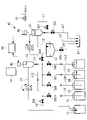
- FIG. 3 is a diagram showing a schematic configuration of the analysis system 40.
- the analysis system 40 includes an electric conductivity meter M1, an intermediate tank C2, a pH meter M2, a pure water tank T2, a calibration liquid tank (T3 to T5), and a control device 50. Is provided as the main configuration.
- the electric conductivity meter M1 measures the electric conductivity of the sample.
- the sampling line 135 is connected to the sample inlet of the analysis system, and the sample is supplied from the sample inlet to the EC tank C1 via the line L1.
- the line L1 is provided with an inlet valve V1 and a valve SV1 and is controlled by a control device 50 described later. Then, the sample is temporarily stored in the EC tank C1. When a predetermined amount or more of the sample is stored in the EC tank C1, the surplus flows out to the line L2.
- the electrode of the electric conductivity meter M1 is immersed in the sample stored in the EC tank C1, and the electric conductivity is measured with respect to the sample.
- the electrode of the electric conductivity meter M1 is, for example, a platinum electrode. Since the sample is automatically supplied to the electric conductivity meter M1 by the control device 50 described later, online measurement of the electric conductivity becomes possible.
- the method for measuring the electrical conductivity is not limited to the glass electrode (platinum electrode cell) method, and various methods can be used.
- a line L7 having a valve SV2 is connected to the EC tank C1 at the bottom of the tank so that stored samples and the like can be discharged to the wastewater pit E1.
- the intermediate tank C2 stores the sample supplied from the line L2.
- a predetermined amount of sample is stored, and the surplus is discharged to the wastewater pit E1 via the line L5.
- the sample stored in the intermediate tank C2 is supplied to the pH tank C3 via the line L3.
- a valve SV4 is provided on the line L3.
- the line L3 is provided with a line L8 having a valve SV9 between the pH tank C3 and the valve SV4, so that the sample of the line L3 can be supplied to the waste liquid tank T1.
- the intermediate tank C2 is provided between the electric conductivity meter M1 and the pH meter M2 in the distribution path through which the sample flows.
- the intermediate tank C2 is provided on the downstream side of the electric conductivity meter M1 and on the upstream side of the pH meter M2 with respect to the flow of the sample.
- the sample is retained for a predetermined time or longer.
- the predetermined time is set based on the time required for the charged charge to be discharged, for example, in the measurement of electric conductivity. That is, the sample can be discharged more reliably by allowing the sample to stay for a predetermined time or longer.
- the residence time of the intermediate tank C2 may be adjusted by the structure (capacity, etc.) of the tank, or may be adjusted by controlling the sample supplied to the pH meter M2 by controlling the pump P1.
- a line L6 having a valve SV3 is connected to the intermediate tank C2 so that stored samples and the like can be discharged to the wastewater pit E1.
- the pH meter M2 measures the pH of the sample. Specifically, the sample is supplied from the intermediate tank C2 to the pH tank C3 via the line L3. Then, the sample is stored in the pH tank C3, and the sample is discharged to the waste liquid tank T1 via the line L4. A pump P1 is provided on the line L4, and a sample is circulated from the intermediate tank C2 to the pH tank C3 and the waste liquid tank T1 by controlling the pump P1.
- the pH meter M2 measures the pH meter M2 by the glass electrode method using an internal comparison solution.
- FIG. 4 is a diagram for explaining the glass electrode method. Two electrodes, a glass electrode Z1 and a comparison electrode Z2, are used. The glass electrode Z1 and the comparison electrode Z2 are immersed in the sample. The lower part of the glass electrode Z1 is formed of a glass thin film Z3, and the glass electrode Z1 is filled with a liquid inside the glass electrode whose pH is known. If there is a difference in pH between the liquid inside the glass electrode and the sample in which the glass electrode Z1 is immersed, a potential difference proportional to the difference is generated in the glass thin film Z3.
- the glass electrode Z1 and the comparison electrode Z2 may be configured as a composite electrode, and the electrode configuration using a specific glass electrode method is not limited to FIG.
- the lower part is the liquid connection portion Z5, and the internal comparison liquid (internal comparison liquid) slightly flows out to the sample side to maintain the electrical connection. Therefore, the amount of the internal comparison liquid in the comparison electrode Z2 decreases.
- the internal comparison liquid is automatically replenished in the control device 50 described later.
- KCl potassium chloride saturated aqueous solution
- the internal comparison solution is an electrolyte solution.
- the pH meter M2 is provided on the downstream side of the electric conductivity meter M1 in the sample distribution path. Then, when the measurement is performed on the sample, the sample is distributed to the distribution channel by the control device 50. Impurities are unlikely to be mixed in the sample in the measurement of electrical conductivity, but impurities such as a comparative solution (KCl, etc.) may be mixed in the sample in the measurement of pH. Therefore, by setting the order of measuring the pH after the electric conductivity, it is possible to more accurately measure the electric conductivity and the pH continuously.
- KCl comparative solution
- the pure water tank T2 is a tank in which pure water is stored.
- the pure water tank T2 is connected to the line L8 via the line L9 having the valve SV5. Further, the pure water tank T2 is connected to the valve SV5 by a line L13 having a pump P2, so that pure water can be supplied to the EC tank C1.
- cleaning is performed using pure water. For example, it is possible to clean the pH meter M2, the pH tank C3, the electric conductivity meter M1, the EC tank C1, the intermediate tank C2, various pipes, and the like.
- the calibration liquid tanks (T3 to T5) store the calibration liquid for constituting the pH meter M2.
- the calibration solution has a predetermined pH value.
- the tank T3, the tank T4, and the tank T5 are provided as the calibration liquid tanks (T3 to T5) corresponding to a plurality of calibration liquids having different pH values will be described.
- One type of calibration solution may be used. However, by providing a plurality of calibration solutions having different pH values, calibration can be performed corresponding to a plurality of pH values, and the pH meter M2 can be calibrated with high accuracy.
- the tank T3 stores a calibration solution having a pH of 4. Then, the tank T3 is connected to the line L8 via the line L10 having the valve SV6.
- the tank T4 stores a calibration solution having a pH of 7. Then, the tank T4 is connected to the line L8 via the line L11 having the valve SV7.
- the tank T5 stores a calibration solution having a pH of 9. Then, the tank T5 is connected to the line L8 via the line L12 having the valve SV8.
- the calibration liquid of the tank T3 is supplied to the pH tank C3 via the line L10, so that the pH meter M2 can be calibrated. It is preferable that the pH tank C3 is free of samples and has been washed before calibration.
- the control device 50 controls various devices in the analysis system 40. Specifically, various valves and pumps are controlled to control the flow of samples.
- FIG. 5 is a diagram showing an example of the hardware configuration of the control device 50 according to the present embodiment.
- the control device 50 is a computer system (computer system), for example, a CPU 11, a ROM (Read Only Memory) 12 for storing a program or the like executed by the CPU 11, and each program at the time of execution. It is provided with a RAM (Random Access Memory) 13 that functions as a work area, a hard disk drive (HDD) 14 as a large-capacity storage device, and a communication unit 15 for connecting to a network or the like.
- a solid state drive (SSD) may be used as the large-capacity storage device.
- SSD solid state drive
- control device 50 may include an input unit including a keyboard, a mouse, and the like, a display unit including a liquid crystal display device for displaying data, and the like.
- the storage medium for storing the program or the like executed by the CPU 11 is not limited to the ROM 12.
- it may be another auxiliary storage device such as a magnetic disk, a magneto-optical disk, or a semiconductor memory.
- a series of processing processes for realizing various functions described later is recorded in the hard disk drive 14 or the like in the form of a program, and the CPU 11 reads this program into the RAM 13 or the like to execute information processing / arithmetic processing.
- the program is installed in ROM 12 or other storage medium in advance, is provided in a state of being stored in a computer-readable storage medium, or is distributed via a wired or wireless communication means. Etc. may be applied.
- the computer-readable storage medium is a magnetic disk, a magneto-optical disk, a CD-ROM, a DVD-ROM, a semiconductor memory, or the like.
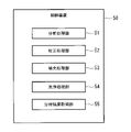
- FIG. 6 is a functional block diagram showing the functions of the control device 50.
- the control device 50 includes an analysis processing unit 51, a calibration processing unit 52, a replenishment processing unit 53, a cleaning processing unit 54, and an analysis result acquisition unit 55.
- the analysis processing unit 51 controls for sample analysis. Specifically, the analysis processing unit 51 distributes the sample to the distribution channel when measuring the sample. That is, control is performed so that the sample flows from the sample inlet to the electric conductivity meter M1 and the pH meter M2.
- FIG. 7 is a diagram showing a sample flow of the analysis system 40 when performing analysis. That is, the inlet valve V1, the valve SV1, and the valve SV4 are opened, and the sample is circulated to the electric conductivity meter M1, the intermediate tank C2, and the pH meter M2 as shown by the thick line in FIG.
- the sample to the pH meter M2 is supplied from the intermediate tank C2 by controlling the pump P2.
- the other valves and pumps are preferably closed (or stopped).
- the sample is automatically supplied to the electric conductivity meter M1 and the pH meter M2 under the control of the analysis processing unit 51, so that automatic measurement can be performed. Further, since the sample is supplied to the electric conductivity meter M1 and the pH meter M2 through each pipe, contact with the outside air can be suppressed.
- the calibration processing unit 52 controls for calibration of the pH meter M2. Specifically, when the pH meter M2 is calibrated, the calibration processing unit 52 supplies the calibration liquid from the calibration liquid tanks (T3 to T5) to the pH meter M2 at a predetermined timing.
- the predetermined timing is a timing preset for starting the configuration, and if it is performed periodically, the calibration cycle may be set in advance.
- FIG. 8 is a diagram showing the flow of the calibration liquid of the analysis system 40 when performing calibration.
- the calibration processing unit 52 opens the valve SV6 and distributes the calibration liquid of the tank T3 to the pH meter M2 (pH tank C3) as shown by the thick line in FIG.
- the calibration liquid to the pH meter M2 is supplied from the tank T3 by controlling the pump P1.
- the calibration liquid is discharged to the waste liquid tank T1 via the pH meter M2.
- the other valves and pumps are preferably closed (or stopped).
- the calibration processing unit 52 calibrates the pH meter M2 in a state where the calibration liquid is supplied to the pH meter M2. Specifically, the calibration processing unit 52 calibrates the pH meter M2 so that the measurement result of the pH meter M2 measuring the supplied calibration solution becomes the known pH value of the calibration solution.
- the specific calibration method of the pH meter M2 is not limited.
- the pH meter M2 Since the calibration solution is supplied to the pH meter M2 at a predetermined timing and the pH meter M2 is calibrated, the pH meter M2 is automatically calibrated. Therefore, the labor of manually calibrating the pH meter M2, which requires periodic calibration, can be reduced. When the calibration is completed, the calibration liquid is discharged via the line L4.
- the replenishment processing unit 53 replenishes the internal comparison liquid in the pH meter M2. As described above, it is necessary to use the comparison electrode in the pH meter M2, but the internal comparison liquid of the comparison electrode decreases. Therefore, the replenishment processing unit 53 supplies the internal comparison liquid to the comparison electrode of the pH meter M2 so that the internal comparison liquid maintains a predetermined amount (necessary amount). Specifically, the internal comparative liquid (KCl) is supplied from the comparative liquid tank T6 to the comparative electrode. When the amount of the internal comparison liquid falls below the threshold value, a predetermined amount of the internal comparison liquid may be replenished.
- the cleaning processing unit 54 controls for cleaning. Specifically, the cleaning processing unit 54 supplies pure water to the equipment to be cleaned when cleaning is performed.
- the cleaning processing unit 54 opens the valve SV5 and distributes the pure water of the pure water tank T2 to the pH meter M2 (pH tank C3) as shown by the thick line in FIG. Pure water to the pH meter M2 is supplied from the pure water tank T2 by controlling the pump P1. Pure water is discharged to the waste liquid tank T1 via the pH meter M2.
- the other valves and pumps are preferably closed (or stopped).
- the cleaning target is not limited to the pH meter M2, and other devices may be targeted. Even when other equipment is to be cleaned, pure water is supplied in the same manner as described above.
- the analysis process, the calibration process, and the cleaning process are executed at different timings, but if the processes can be performed in parallel, the processes may be executed in parallel.
- the analysis result acquisition unit 55 acquires measurement results from the pH meter M2 and the electric conductivity meter M1.
- the acquired measurement result may be notified by display or the like, or may be automatically transmitted by, for example, a remote device. In this embodiment, the measurement result is sent to the notification system described later.
- FIG. 10 is a flowchart showing an example of the procedure of the calibration process according to the present embodiment.
- the flow shown in FIG. 10 is executed, for example, at a predetermined timing for performing calibration.
- the flow shown in FIG. 10 may be executed at a preset cycle for performing calibration.
- the analysis process is stopped (S101). That is, when the sample is distributed to the pH meter M2, the valve or the like is controlled to stop the distribution of the sample.
- a cleaning process is executed for the pH meter M2 (S102). That is, pure water is circulated to the pH meter M2 to wash away the sample.
- the calibration liquid is supplied to the pH meter M2 (S103).
- each valve or the like is controlled to supply the calibration liquid of the tank T3 to the pH meter M2.
- the pH meter M2 is calibrated while the calibration liquid is being supplied to the pH meter M2 (S104).
- the calibration liquid is supplied to the pH meter M2 and the calibration is executed.
- the processes S102 to S104 may be executed by changing the type of calibration solution.
- the cleaning process is performed in S102, but if cleaning is not required, the process in S102 may be omitted.
- FIG. 11 is a flowchart showing an example of the procedure of the cleaning process according to the present embodiment.
- the flow shown in FIG. 11 is executed, for example, at a predetermined timing for performing cleaning.
- the flow shown in FIG. 11 may be performed at a preset cycle for performing cleaning.
- the case of cleaning the pH meter M2 will be described with reference to FIG. 11, the same applies to the case where another device is targeted for cleaning.
- the analysis process is stopped (S201). That is, when the sample is distributed to the pH meter M2, the valve or the like is controlled to stop the distribution of the sample.
- the calibration process is stopped (S202). That is, when the calibration liquid is distributed to the pH meter M2, the valve or the like is controlled to stop the distribution of the calibration liquid.
- the cleaning liquid is supplied to the pH meter M2 (S203).
- each valve or the like is controlled to supply the pure water of the pure water tank T2 to the pH meter M2. That is, pure water is circulated to the pH meter M2 to wash away the sample.
- a pH meter M2 and a tank in which a calibration solution having a known pH value is stored are provided. Since the calibration solution is supplied to the pH meter M2 at a predetermined cycle and the pH meter M2 is calibrated, the pH meter M2 is automatically calibrated. Therefore, the labor of manually calibrating the pH meter M2, which requires periodic calibration, can be reduced.
- calibration can be performed corresponding to a plurality of pH values, and the pH meter M2 can be calibrated with high accuracy.
- Impurities are unlikely to be mixed in the sample in the measurement of electrical conductivity, but impurities such as comparative liquid (KCl, etc.) may be mixed in the sample in the measurement of pH. Therefore, by setting the order of measuring the pH after the electric conductivity, it is possible to more accurately measure the electric conductivity and the pH continuously.
- impurities such as comparative liquid (KCl, etc.) may be mixed in the sample in the measurement of pH. Therefore, by setting the order of measuring the pH after the electric conductivity, it is possible to more accurately measure the electric conductivity and the pH continuously.
- the management system according to this embodiment is applied to the processing tank 122 as shown in FIG. Similar to FIG. 2, the circulation system 130 and the analysis system 40 are connected to the processing tank 122.
- An adjustment system 160 is connected to the processing tank 122. That is, the management system is composed of the analysis system 40 and the adjustment system 160.
- the adjustment system 160 acquires the measurement result in the analysis system 40 and adjusts at least one of pH and electrical conductivity with respect to the sample based on the measurement result. As shown in FIG. 12, the adjustment system 160 is provided with a chemical tank 163, a pure water tank 162, and an addition control device 161.
- the chemical tank 163 stores the pH adjusting chemical solution.
- the chemical tank 163 is connected to the processing tank 122 by the supply line W1. That is, the pH adjusting chemical solution is added to the treatment liquid in the treatment tank 122.
- the supply line W1 is provided with a solenoid valve (not shown), a flow meter (not shown), and a pump (not shown). The solenoid valve and the pump are controlled by the addition control device 161 described later. The measurement result of the flow meter is transmitted to the addition control device 161.
- Pure water is stored in the pure water tank 162.
- the pure water tank 162 is connected to the processing tank 122 by the supply line W2. That is, pure water is added to the treatment liquid in the treatment tank 122.
- the supply line W2 is provided with a solenoid valve (not shown), a flow meter (not shown), and a pump (not shown).
- the solenoid valve and the pump are controlled by the addition control device 161 described later.
- the measurement result of the flow meter is transmitted to the addition control device 161.
- the addition control device 161 controls the addition amount based on the measurement result of the analysis system 40.
- the control device 50 is composed of a computer system (computer system) as shown in FIG.
- the control device 50 and the addition control device 161 may be configured by different computer systems, or may be integrated into one computer system.
- the addition control device 161 adjusts the pH by adjusting the input amount of the pH adjusting chemical solution.
- the pH of the treatment solution is controlled so as to be within a predetermined reference range. For example, when the pH exceeds the upper limit of the reference range, a pH adjusting chemical solution is added so as to lower the pH by a predetermined value. When the pH falls below the lower limit of the reference range, a pH adjusting chemical solution is added so as to raise the pH by a predetermined value.
- the solenoid valve is opened and the pump is used while checking the input amount with a flow meter.
- the method of adjusting the pH is not limited to the above. For example, the input amount may be determined according to the detected pH value.
- the addition control device 161 adjusts the electric conductivity by adjusting the input amount of pure water. Since the electric conductivity becomes abnormal when it is high, the electric conductivity is lowered by adding pure water to dilute it. For example, when the electric conductivity exceeds the upper limit of the reference range, pure water is added so as to lower the electric conductivity by a predetermined value. For example, the solenoid valve is opened and the pump is used while checking the input amount with a flow meter.
- the method for adjusting the electric conductivity is not limited to the above. For example, the input amount may be determined according to the detected value of the electric conductivity.
- the management system may be provided with a notification system (not shown).
- the notification system acquires the measurement result from the analysis system 40 and notifies the abnormality when the measurement result is not within the preset control reference range.
- the notification may be performed in the equipment provided with the surface treatment line 120, or may be performed by transmitting information to the remote equipment. By notifying the abnormality when it is out of the control standard range, it is possible to prevent the abnormal state from being left unattended.
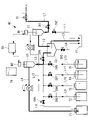
- FIG. 13 is an overall configuration example when the management system according to this embodiment is applied to a production line. As shown in FIG. 13, a sample is collected from a controlled processing tank in a production line and analyzed by an analysis system 40. Then, the adjustment system 160 automatically inputs the chemical solution and the like. In this way, the treatment liquid in each management target treatment tank is managed.
- the analysis method, and the analysis program according to the present embodiment at least one of pH and electrical conductivity is adjusted based on the measurement result.
- the liquid property of the sample can be automatically adjusted. This makes it possible to reduce human error and work time by workers and the like.
- the analysis system (40) includes a pH meter (M2) for measuring the pH of a sample, tanks (T3, T4, T5) in which a calibration solution having a predetermined pH value is stored, and the tank (T3, T5). Control to supply the calibration solution from T4, T5) to the pH meter (M2) at a predetermined timing and calibrate the pH meter (M2) while the calibration solution is supplied to the pH meter (M2).
- the device (50) is provided.
- a pH meter (M2) and tanks (T3, T4, T5) in which a calibration solution having a known pH value is stored are provided, and calibration is performed at a predetermined timing. Since the liquid is supplied to the pH meter (M2) and the pH meter (M2) is calibrated, the pH meter (M2) is automatically calibrated. Therefore, it is possible to reduce the trouble of manually calibrating the pH meter (M2) that needs to be calibrated on a regular basis.
- the tanks (T3, T4, T5) may be provided corresponding to a plurality of calibration solutions having different pH values.
- the analysis system (40) by providing a plurality of calibration solutions having different pH values, calibration can be performed corresponding to a plurality of pH values, and the pH meter (M2) can be calibrated with high accuracy. can do.
- the analysis system (40) includes an electric conductivity meter (M1) for measuring the electric conductivity of the sample, and the pH meter (M2) is the electric conductivity meter (M2) in the distribution channel of the sample.
- the control device (50) which is provided on the downstream side of M1), may distribute the sample to the distribution channel when measuring the sample.
- Impurities are unlikely to be mixed in the sample in the measurement of electrical conductivity, but impurities such as comparative liquid (KCl, etc.) may be mixed in the sample in the measurement of pH. Therefore, by setting the order of measuring the pH after the electric conductivity, it is possible to more accurately measure the electric conductivity and the pH continuously.
- impurities such as comparative liquid (KCl, etc.) may be mixed in the sample in the measurement of pH. Therefore, by setting the order of measuring the pH after the electric conductivity, it is possible to more accurately measure the electric conductivity and the pH continuously.
- the analysis system (40) is provided between the electric conductivity meter (M1) and the pH meter (M2) in the distribution path of the sample, and has an intermediate tank (C2) for storing the sample. It may be prepared.
- an intermediate tank (C2) for storing a sample is provided between the electric conductivity meter (M1) and the pH meter (M2), so that the sample can be measured for electric conductivity. Even if it is charged, it can be discharged before the pH meter (M2) measurement is performed. Therefore, it becomes possible to perform pH meter (M2) measurement more accurately.
- the sample may be retained in the intermediate tank (C2) for a predetermined time or longer.
- the pH meter (M2) measures the pH meter (M2) by a glass electrode method using an internal comparison solution, and the control device (50) uses the pH meter (50).
- the internal comparison solution may be supplied to the pH meter (M2) so that the internal comparison solution in M2) maintains a predetermined amount.
- the pH meter (M2) uses the glass electrode method using the internal comparison solution, a predetermined amount of the internal comparison solution is required for measurement. Since the internal comparison liquid is supplied to the pH meter (M2) by the control device (50) so as to maintain a predetermined amount, stable measurement can be performed using the pH meter (M2). Then, the trouble of manually replenishing the internal comparison liquid can be suppressed.
- the management system acquires the measurement results of the analysis system (40) and the analysis system (40), and based on the measurement results, at least one of pH and electrical conductivity with respect to the sample. It is equipped with an adjustment system (160) that adjusts one side.
- the liquid property of the sample can be automatically adjusted by adjusting at least one of pH and electrical conductivity based on the measurement result.
- the adjustment system (160) may adjust the pH by adjusting the input amount of the pH adjustment chemical solution.
- the pH can be adjusted by a pH adjusting chemical solution.
- the adjustment system (160) may adjust the electric conductivity by adjusting the input amount of pure water.
- the electric conductivity can be adjusted by pure water.
- the management system according to the present disclosure may be provided with a notification system for notifying an abnormality when the measurement result is not within the preset management standard range.
- the management system it is possible to prevent the abnormal state from being left unattended by notifying the abnormality when it deviates from the control standard range.
- the analysis system (40) is provided with an electric conductivity meter (M1) for measuring the electric conductivity of a sample and a downstream side of the electric conductivity meter (M1) in the distribution path of the sample.
- a pH meter (M2) for measuring the pH of the sample and a control device (50) for distributing the sample to the distribution channel when measuring the sample are provided.
- Impurities are unlikely to be mixed in the sample in the measurement of electrical conductivity, but impurities such as comparative liquid (KCl, etc.) may be mixed in the sample in the measurement of pH. Therefore, by setting the order of measuring the pH after the electric conductivity, it is possible to more accurately measure the electric conductivity and the pH continuously.
- impurities such as comparative liquid (KCl, etc.) may be mixed in the sample in the measurement of pH. Therefore, by setting the order of measuring the pH after the electric conductivity, it is possible to more accurately measure the electric conductivity and the pH continuously.
- a pH meter (M2) for measuring the pH of a sample by a glass electrode method using an internal comparison solution and the internal comparison solution in the pH meter (M2) maintain a predetermined amount.
- a control device (50) for supplying the internal comparison liquid to the pH meter (M2) is provided.
- the pH meter (M2) uses the glass electrode method using the internal comparison solution, a predetermined amount of the internal comparison solution is required for measurement. Since the internal comparison liquid is supplied to the pH meter (M2) by the control device (50) so as to maintain a predetermined amount, stable measurement can be performed using the pH meter (M2). Then, the trouble of manually replenishing the internal comparison liquid can be suppressed.
- the analysis method according to the present disclosure is an analysis of an analysis system (40) including a pH meter (M2) for measuring the pH of a sample and tanks (T3, T4, T5) in which a calibration solution having a predetermined pH value is stored.
- the method is a step of supplying the calibration solution from the tanks (T3, T4, T5) to the pH meter (M2) at a predetermined timing, and the calibration solution is supplied to the pH meter (M2). It comprises a step of calibrating the pH meter (M2) in a state.
- the analysis program according to the present disclosure is an analysis of an analysis system (40) including a pH meter (M2) for measuring the pH of a sample and tanks (T3, T4, T5) in which a calibration solution having a predetermined pH value is stored.
- a pH meter M2 for measuring the pH of a sample and tanks (T3, T4, T5) in which a calibration solution having a predetermined pH value is stored.
- the process of calibrating the pH meter (M2) in the state is performed by a computer.
Abstract
pH計の校正の手間を軽減することのできる分析システム及び管理システム、並びに分析方法、並びに分析プログラムを提供することを目的とする。分析システム40は、試料のpHを計測するpH計M2と、所定のpH値の校正液が溜められたタンクT3~T4と、タンクT3~T4から校正液を所定のタイミングでpH計M2へ供給し、そして校正液がpH計M2へ供給されている状態においてpH計M2を校正する制御装置50とを備える。
Description
本開示は、分析システム及び管理システム、並びに分析方法、並びに分析プログラムに関するものである。
例えば航空機部品の生産では、処理液を用いたエッチングや皮膜処理などといった表面処理が行われる。所望の表面処理が行われるように処理液の液性は管理されている。例えば、作業員等により定期的(1回/週など)に処理液を採取して手分析により液性検査が行われている。
特許文献1には、エッチング処理液(HF溶液)をパイプを介して処理槽から濃度測定器へ供給し、濃度値を検出することが開示されている。
処理液は、処理を行う部品数や製品の材質などに応じて、液性(例えば濃度)の急激な変化が起こる場合がある。例えばpHや電気伝導率は、不純物や大気の溶解成分の影響によって変化し易い。処理液の液性が適切に保たれないと、処理した製品が不適合製品(不良品)となる場合もあるため、処理液の液性をより正確に管理することの重要性が高まっている。
pH計は定期的に校正を行う必要がある機器であるため、作業員等によって手動で校正が実施されている。このため処理液の液性を管理するためにpH計を定期的に校正する手間がかかっていた。
本開示は、このような事情に鑑みてなされたものであって、pH計の校正の手間を軽減することのできる分析システム及び管理システム、並びに分析方法、並びに分析プログラムを提供することを目的とする。
本開示の第1態様は、試料のpHを計測するpH計と、所定のpH値の校正液が溜められたタンクと、前記タンクから前記校正液を所定のタイミングで前記pH計へ供給し、前記校正液が前記pH計へ供給されている状態において前記pH計を校正する制御装置と、を備える分析システムである。
本開示の第2態様は、試料のpHを計測するpH計と、所定のpH値の校正液が溜められたタンクとを備える分析システムの分析方法であって、前記タンクから前記校正液を所定のタイミングで前記pH計へ供給する工程と、前記校正液が前記pH計へ供給されている状態において前記pH計を校正する工程と、を有する分析方法である。
本開示の第3態様は、試料のpHを計測するpH計と、所定のpH値の校正液が溜められたタンクとを備える分析システムの分析プログラムであって、前記タンクから前記校正液を所定のタイミングで前記pH計へ供給する処理と、前記校正液が前記pH計へ供給されている状態において前記pH計を校正する処理と、をコンピュータに実行させるための分析プログラムである。
本開示によれば、pH計の校正の手間を軽減することができるという効果を奏する。
〔第1実施形態〕
以下に、本開示に係る分析システム及び管理システム、並びに分析方法、並びに分析プログラムの第1実施形態について、図面を参照して説明する。
以下に、本開示に係る分析システム及び管理システム、並びに分析方法、並びに分析プログラムの第1実施形態について、図面を参照して説明する。
図1は、表面処理ライン120の構成例を示す図である。表面処理ライン120では、複数の処理液が溜められた処理槽122が設けられている。例えば図1に示すように、表面処理ライン120には、硼酸硫酸処理槽122aや、1次水洗処理槽122b、2次水洗処理槽122cといった処理槽122が設けられている。そして、処理槽122の上部にはクレーン121が設けられており、クレーン121によって対象部品123を吊るして、上下動作により対象部品123を処理槽122の処理液に浸漬する。ラインの上流側から順番に対象部品123を各処理液に浸漬することによって、各表面処理が行われる。
硼酸硫酸処理槽122aでは、皮膜処理が行われる。そして、1次水洗処理槽122b及び2次水洗処理槽122cでは、皮膜処理後の対象部品123に対して、1次水洗及び2次水洗が行われる。1次水洗処理槽122b及び2次水洗処理槽122cには純水が溜められている。純水は蒸発等により貯留量が減少するため、純水ライン(不図示)から純水の補給がされる。
本実施形態では、1次水洗処理槽122b(または2次水洗処理槽122c)に貯められた純水を、液性の分析対象(以下、「試料」という)とする場合を例として説明する。試料としては、純水ラインから補給される純水とすることとしてもよい。また、純水以外であっても、硼酸硫酸処理槽122aの処理液など様々な溶液を試料とすることが可能である。
図2は、処理槽122に分析システム40を適用した場合の構成例を示す図である。図2の処理槽122とは、例えば1次水洗処理槽122bである。処理槽122には循環システム130と分析システム40とが接続されている。
循環システム130は、処理槽122の処理液をポンプ131によって一部抜き取り、循環ライン133を介して処理液を処理槽122に戻す。循環ライン133におけるポンプ131の下流側では、循環ライン133の処理液の一部が迂回ライン134を流通し、ストレーナー132で固形成分が取り除かれ、循環ライン133へ戻る。迂回ライン134におけるストレーナー132の下流側には採取ライン135が接続されている。
分析システム40は、採取ライン135より処理液を試料として採取して分析を行う。本実施形態では、処理液のpHと電気伝導率とを計測(分析)する場合について説明するが、pH及び電気伝導率のいずれか一方を計測することとしてもよい。
図3は、分析システム40の概略構成を示す図である。図3に示すように、分析システム40は、電気伝導率計M1と、中間タンクC2と、pH計M2と、純水タンクT2と、校正液用タンク(T3~T5)と、制御装置50とを主な構成として備えている。
電気伝導率計M1は、試料の電気伝導率を計測する。具体的には、採取ライン135が分析システム試料入口へ接続されており、試料入口からラインL1を介してEC用タンクC1へ試料が供給される。ラインL1には入口バルブV1とバルブSV1が設けられており、後述する制御装置50によって制御される。そして、EC用タンクC1に試料が一時貯留される。EC用タンクC1において所定量以上の試料が貯留されると余剰分はラインL2へ流れ出る。
EC用タンクC1に貯留した試料には電気伝導率計M1の電極が浸るようになっており、試料に対して電気伝導率が計測される。電気伝導率計M1の電極は例えば白金電極である。後述する制御装置50によって試料が自動的に電気伝導率計M1へ供給されるため、電気伝導率のオンライン計測を行うことが可能となる。なお、電気伝導率の計測方法は、ガラス電極(白金電極セル)法に限らず様々な方法を用いることができる。
EC用タンクC1には、タンク下部にバルブSV2を有するラインL7が接続されており貯留された試料等を廃水ピットE1へ排出可能となっている。
中間タンクC2は、ラインL2から供給された試料を溜める。中間タンクC2では、所定量の試料が貯留され、余剰分はラインL5を介して廃水ピットE1へ排出される。中間タンクC2へ貯留された試料は、ラインL3を介してpH用タンクC3へ供給される。ラインL3にはバルブSV4が設けられている。また、ラインL3にはpH用タンクC3とバルブSV4の間にバルブSV9を有するラインL8が設けられており、ラインL3の試料を廃液タンクT1へ供給可能となっている。
すなわち、中間タンクC2は、試料が流通する流通経路における電気伝導率計M1とpH計M2の間に設けられている。換言すると、中間タンクC2は、試料の流れに対して電気伝導率計M1の下流側であってpH計M2の上流側に設けられている。電気伝導率計M1とpH計M2の間に試料を溜める中間タンクC2が設けられることによって、電気伝導率の計測で試料が帯電した場合でもpH計M2測を行う前に放電することができる。このため、より正確にpH計M2測を行うことが可能となる。
中間タンクC2では、試料が所定時間以上滞留されることが好ましい。所定時間は、例えば電気伝導率の計測で帯電した電荷が放電されるのに要する時間に基づいて設定される。すなわち、試料が所定時間以上滞留がれることによってより確実に試料の放電を行うことができる。中間タンクC2の滞留時間は、タンクの構造(容量等)によって調整されてもよいし、ポンプP1の制御によってpH計M2へ供給される試料を制御して調整されることとしてもよい。
中間タンクC2には、タンク下部にバルブSV3を有するラインL6が接続されており貯留された試料等を廃水ピットE1へ排出可能となっている。
pH計M2は、試料のpHを計測する。具体的には、ラインL3を介して中間タンクC2からpH用タンクC3へ試料が供給される。そしてpH用タンクC3に試料が溜められ、ラインL4を介して廃液タンクT1へ試料が排出される。ラインL4にはポンプP1が設けられており、ポンプP1が制御されることによって中間タンクC2からpH用タンクC3、そして廃液タンクT1へ試料が流通される。
pH計M2は、内部比較液を用いたガラス電極法によりpH計M2測を行う。図4はガラス電極法を説明するための図である。ガラス電極Z1と比較電極Z2の2つの電極が用いられる。ガラス電極Z1及び比較電極Z2は試料に浸されている。ガラス電極Z1は下部がガラス薄膜Z3で構成されており、ガラス電極Z1にはpHが既知であるガラス電極内部液が満たされている。ガラス電極内部液と、ガラス電極Z1が浸された試料とにpHの差があると該差に比例した電位差がガラス薄膜Z3に発生する。すなわち、ガラス薄膜Z3におけるガラス電極内部液側と、試料側とにそれぞれ電位が発生する。ガラス電極内部液側に発生した電位はガラス電極Z1の内部電極Z4で計り、試料側に発生した電位は比較電極Z2の内部電極Z6で計り、電位差が取得される。電位差はpHが既知であるガラス電極内部液と試料のpHの差に比例しているため、電位差によって試料のpHがわかることとなる。なお、ガラス電極Z1と比較電極Z2とは複合電極として構成されていてもよく、具体的なガラス電極法を用いた電極構成は図4に限定されない。
比較電極Z2では、下部が液絡部Z5となっており、内部の比較液(内部比較液)が試料側にわずかに流出して電気的接続を保っている。このため比較電極Z2における内部比較液は減少する。内部比較液は、後述する制御装置50において自動補充される。内部比較液としてはKCl(塩化カリウム飽和水溶液)が用いられる。内部比較液は、電解質溶液である。
pH計M2は、試料の流通経路において電気伝導率計M1の下流側に設けられている。そして、試料に対する計測を行う場合に、制御装置50により試料が流通経路へ流通させられる。電気伝導率の計測では試料に不純物が混入しにくいが、pHの計測では例えば比較液(KCl等)といった不純物が試料に混入する場合がある。このため、電気伝導率の後にpHを計測する順番とすることで、より正確に、電気伝導率とpHの連続計測が可能となる。
純水タンクT2は、純水が溜められているタンクである。純水タンクT2は、バルブSV5を有するラインL9を介してラインL8と接続されている。また、純水タンクT2は、バルブSV5との間にポンプP2を有するラインL13が接続されており、純水がEC用タンクC1へ供給可能となっている。分析システム40では純水を用いて例えば洗浄が行われる。例えば、pH計M2や、pH用タンクC3、電気伝導率計M1、EC用タンクC1、中間タンクC2、各種配管等の洗浄が可能となっている。
校正液用タンク(T3~T5)は、pH計M2を構成するための校正液が溜められている。校正液は、所定のpH値となっている。本実施形態では、校正液用タンク(T3~T5)として、pH値の異なる複数の校正液に対応してそれぞれタンクT3、タンクT4、及びタンクT5が設けられている場合について説明する。校正液については1種類用いることとしてもよい。しかしながら、pH値の異なる校正液が複数設けられることによって、複数のpH値に対応して校正を行うことができ、pH計M2を精度よく校正することができる。
タンクT3は、pHが4の校正液が貯留されている。そして、タンクT3は、バルブSV6を有するラインL10を介してラインL8と接続されている。タンクT4は、pHが7の校正液が貯留されている。そして、タンクT4は、バルブSV7を有するラインL11を介してラインL8と接続されている。タンクT5は、pHが9の校正液が貯留されている。そして、タンクT5は、バルブSV8を有するラインL12を介してラインL8と接続されている。
例えば、タンクT3の校正液がラインL10を介してpH用タンクC3へ供給されることによってpH計M2の校正が可能となる。なお、校正を行う前にはpH用タンクC3に試料がなく、また、洗浄がされていることが好ましい。
制御装置50は、分析システム40における各種機器を制御する。具体的には、各種のバルブやポンプを制御して試料の流通を制御する。
図5は、本実施形態に係る制御装置50のハードウェア構成の一例を示した図である。
図5に示すように、制御装置50は、コンピュータシステム(計算機システム)であり、例えば、CPU11と、CPU11が実行するプログラム等を記憶するためのROM(Read Only Memory)12と、各プログラム実行時のワーク領域として機能するRAM(Random Access Memory)13と、大容量記憶装置としてのハードディスクドライブ(HDD)14と、ネットワーク等に接続するための通信部15とを備えている。なお、大容量記憶装置としては、ソリッドステートドライブ(SSD)を用いることとしてもよい。これら各部は、バス18を介して接続されている。
図5に示すように、制御装置50は、コンピュータシステム(計算機システム)であり、例えば、CPU11と、CPU11が実行するプログラム等を記憶するためのROM(Read Only Memory)12と、各プログラム実行時のワーク領域として機能するRAM(Random Access Memory)13と、大容量記憶装置としてのハードディスクドライブ(HDD)14と、ネットワーク等に接続するための通信部15とを備えている。なお、大容量記憶装置としては、ソリッドステートドライブ(SSD)を用いることとしてもよい。これら各部は、バス18を介して接続されている。
また、制御装置50は、キーボードやマウス等からなる入力部や、データを表示する液晶表示装置等からなる表示部などを備えていてもよい。
なお、CPU11が実行するプログラム等を記憶するための記憶媒体は、ROM12に限られない。例えば、磁気ディスク、光磁気ディスク、半導体メモリ等の他の補助記憶装置であってもよい。
後述の各種機能を実現するための一連の処理の過程は、プログラムの形式でハードディスクドライブ14等に記録されており、このプログラムをCPU11がRAM13等に読み出して、情報の加工・演算処理を実行することにより、後述の各種機能が実現される。なお、プログラムは、ROM12やその他の記憶媒体に予めインストールしておく形態や、コンピュータ読み取り可能な記憶媒体に記憶された状態で提供される形態、有線又は無線による通信手段を介して配信される形態等が適用されてもよい。コンピュータ読み取り可能な記憶媒体とは、磁気ディスク、光磁気ディスク、CD-ROM、DVD-ROM、半導体メモリ等である。
図6は、制御装置50が備える機能を示した機能ブロック図である。図6に示されるように、制御装置50は、分析処理部51と、校正処理部52と、補充処理部53と、洗浄処理部54と、分析結果取得部55とを備えている。
分析処理部51は、試料の分析のために制御を行う。具体的には、分析処理部51は、試料に対する計測を行う場合に、試料を流通経路へ流通させる。すなわち、試料入口から電気伝導率計M1、pH計M2へ試料が流通するように制御を行う。
図7は分析を行う場合の分析システム40の試料の流れを示す図である。すなわち、入口バルブV1と、バルブSV1と、バルブSV4とを開として、図7の太線として示すように試料を電気伝導率計M1、中間タンクC2、及びpH計M2へ流通させる。pH計M2への試料は、ポンプP2が制御されることにより中間タンクC2から供給される。なお、その他のバルブ及びポンプは閉(または停止)となっていることが好ましい。
このように分析処理部51の制御によって試料が自動的に電気伝導率計M1及びpH計M2へ供給されるため、自動計測を行うことができる。また、各配管を通じて電気伝導率計M1及びpH計M2へ試料が供給されるため、外気との接触も抑制することができる。
校正処理部52は、pH計M2の校正のために制御を行う。具体的には、校正処理部52は、pH計M2の校正を行う場合に、校正液用タンク(T3~T5)から校正液を所定のタイミングでpH計M2へ供給する。所定のタイミングとは構成を開始するために予め設定されたタイミングであり、周期的に行う場合には予め校正周期を設定しておくこととしてもよい。
図8は校正を行う場合の分析システム40の校正液の流れを示す図である。なお図8ではタンクT3の校正液を用いる場合を例とする。校正処理部52は、バルブSV6とを開として、図8の太線として示すようにタンクT3の校正液をpH計M2(pH用タンクC3)へ流通させる。pH計M2への校正液は、ポンプP1が制御されることによりタンクT3から供給される。校正液はpH計M2を介して廃液タンクT1へ排出される。なお、その他のバルブ及びポンプは閉(または停止)となっていることが好ましい。
そして、校正処理部52は、校正液がpH計M2へ供給されている状態においてpH計M2を校正する。具体的には、校正処理部52は、供給された校正液を計測中のpH計M2の計測結果が、該校正液の既知pH値となるようにpH計M2を校正する。pH計M2の具体的な校正方法については限定されない。
所定のタイミングで校正液がpH計M2へ供給されてpH計M2が校正されるため、pH計M2の自動校正が行われる。このため、定期的に校正が必要なpH計M2を手動で校正する手間が抑えられる。校正が終了すると、校正液はラインL4を介して排出される。
補充処理部53は、pH計M2における内部比較液の補充を行う。前述のようにpH計M2では比較電極を用いる必要があるが比較電極の内部比較液は減少していく。このため、補充処理部53は、内部比較液が所定量(必要量)を維持するように、内部比較液をpH計M2の比較電極へ供給する。具体的には、比較液タンクT6から内部比較液(KCl)を比較電極へ供給する。なお、内部比較液の量がしきい値を下回った場合に所定量の内部比較液を補充することとしてもよい。
洗浄処理部54は、洗浄のために制御を行う。具体的には、洗浄処理部54は、洗浄を行う場合に、洗浄対象の機器へ純水を供給する。図9では、pH計M2(及びpH用タンクC3)を洗浄する場合を一例として説明する。すなわち、洗浄処理部54は、バルブSV5とを開として、図9の太線として示すように純水タンクT2の純水をpH計M2(pH用タンクC3)へ流通させる。pH計M2への純水は、ポンプP1が制御されることにより純水タンクT2から供給される。純水はpH計M2を介して廃液タンクT1へ排出される。なお、その他のバルブ及びポンプは閉(または停止)となっていることが好ましい。
なお、洗浄対象はpH計M2に限定されず、他の機器を対象としてもよい。他の機器を洗浄対象とする場合であっても、上記と同様に純水が供給される。
洗浄処理部54によって純水の供給制御がされるため、洗浄を自動的に行うことができる。純水はラインL4を介して排出される。
分析処理、校正処理、及び洗浄処理についてはそれぞれ異なるタイミングで実行されることが好ましいが、並列して処理が可能な場合には並列して処理が実行されてもよい。
分析結果取得部55は、pH計M2及び電気伝導率計M1から計測結果を取得する。取得した計測結果は表示等により通知が行われることとしてもよいし、例えば遠隔のデバイスで自動送信されることとしてもよい。本実施形態では、計測結果は後述する通知システムへ送られる。
次に、上述の制御装置50による校正処理の一例について図10を参照して説明する。図10は、本実施形態に係る校正処理の手順の一例を示すフローチャートである。図10に示すフローは、例えば、校正を実施する所定のタイミングで実行される。図10に示すフローは、校正を実施するために予め設定された周期で実行されてもよい。
まず、分析処理を実行している場合には、分析処理を停止する(S101)。すなわち、試料がpH計M2へ流通している場合にはバルブ等を制御して試料の流通を停止させる。
次に、pH計M2に対して洗浄処理を実行する(S102)。すなわち、純水をpH計M2へ流通させて、試料を洗い流す。
次に、校正液をpH計M2へ供給する(S103)。例えば図8のように各バルブ等を制御して、タンクT3の校正液をpH計M2へ供給する。
次に、校正液がpH計M2へ供給されている状態において、pH計M2の校正を実行する(S104)。
このようにして、pH計M2へ校正液が供給されて校正が実行される。校正液が複数ある場合には、S102からS104の処理を校正液の種類を変えて実行することとしてもよい。
図10ではS102において洗浄処理を行っているが、洗浄が不要な場合にはS102の処理を省略することとしてもよい。
次に、上述の制御装置50による洗浄処理の一例について図11を参照して説明する。図11は、本実施形態に係る洗浄処理の手順の一例を示すフローチャートである。図11に示すフローは、例えば、洗浄を実施する所定のタイミングで実行される。図11に示すフローは、洗浄を実施するために予め設定された周期で実行されてもよい。図11ではpH計M2を洗浄する場合について説明するが、他の機器を洗浄対象とする場合も同様に適用される。
まず、分析処理を実行している場合には、分析処理を停止する(S201)。すなわち、試料がpH計M2へ流通している場合にはバルブ等を制御して試料の流通を停止させる。
次に、校正処理を実行している場合には、校正処理を停止する(S202)。すなわち、校正液がpH計M2へ流通している場合にはバルブ等を制御して校正液の流通を停止させる。
次に、洗浄液をpH計M2へ供給する(S203)。例えば図9のように各バルブ等を制御して、純水タンクT2の純水をpH計M2へ供給する。すなわち、純水をpH計M2へ流通させて、試料を洗い流す。
以上説明したように、本実施形態に係る分析システム及び管理システム、並びに分析方法、並びに分析プログラムによれば、pH計M2と、pH値が既知の校正液が溜められたタンクが設けられており、所定周期で校正液がpH計M2へ供給されてpH計M2が校正されるため、pH計M2の自動校正が行われる。このため、定期的に校正が必要なpH計M2を手動で校正する手間が抑えられる。
pH値の異なる校正液が複数設けられることによって、複数のpH値に対応して校正を行うことができ、pH計M2を精度よく校正することができる。
電気伝導率の計測では試料に不純物が混入しにくいが、pHの計測では例えば比較液(KCl等)といった不純物が試料に混入する場合がある。このため、電気伝導率の後にpHを計測する順番とすることで、より正確に、電気伝導率とpHの連続計測が可能となる。
電気伝導率計M1とpH計M2の間に試料を溜める中間タンクC2が設けられることによって、電気伝導率の計測で試料が帯電した場合でもpH計M2測を行う前に放電することができる。このため、より正確にpH計M2測を行うことが可能となる。
〔第2実施形態〕
次に、本開示の第2実施形態に係る分析システム及び管理システム、並びに分析方法、並びに分析プログラムについて説明する。
本実施形態では、試料の液性を自動調整する場合について説明する。以下、本実施形態に係る分析システム及び管理システム、並びに分析方法、並びに分析プログラムについて、第1実施形態と異なる点について主に説明する。
次に、本開示の第2実施形態に係る分析システム及び管理システム、並びに分析方法、並びに分析プログラムについて説明する。
本実施形態では、試料の液性を自動調整する場合について説明する。以下、本実施形態に係る分析システム及び管理システム、並びに分析方法、並びに分析プログラムについて、第1実施形態と異なる点について主に説明する。
本実施形態に係る管理システムは、図12に示すように処理槽122に適用される。図2と同様に、処理槽122に対して循環システム130と分析システム40とが接続されている。そして、処理槽122には調整システム160が接続されている。すなわち、分析システム40と調整システム160とで管理システムが構成される。
調整システム160は、分析システム40における計測結果を取得し、計測結果に基づいて試料に対してpH及び電気伝導率の少なくともいずれか1方を調整する。調整システム160は、図12に示すように、薬品タンク163と、純水タンク162と、添加制御装置161とが設けられている。
薬品タンク163は、pH調整薬液が貯留されている。そして、薬品タンク163は、供給ラインW1によって処理槽122と接続されている。すなわち、pH調整薬液は処理槽122の処理液に対して添加される。供給ラインW1には、電磁弁(不図示)と、流量計(不図示)と、ポンプ(不図示)とが設けられている。電磁弁とポンプは後述する添加制御装置161によって制御される。流量計の計測結果は添加制御装置161へ送信される。
純水タンク162は、純水が貯留されている。そして、純水タンク162は、供給ラインW2によって処理槽122と接続されている。すなわち、純水は処理槽122の処理液に対して添加される。供給ラインW2には、電磁弁(不図示)と、流量計(不図示)と、ポンプ(不図示)とが設けられている。電磁弁とポンプは後述する添加制御装置161によって制御される。流量計の計測結果は添加制御装置161へ送信される。
添加制御装置161は、分析システム40の計測結果に基づいて添加量を制御する。例えば制御装置50と同様に図5に示すようなコンピュータシステム(計算機システム)で構成される。制御装置50と添加制御装置161とは、異なるコンピュータシステムにより構成されることとしてもよいし、1つのコンピュータシステムに集約することとしてもよい。
添加制御装置161は、pH調整薬液の投入量を調整することによってpHを調整する。pH調整薬液を投入することによって処理液のpHを所定の基準範囲内に収まるように制御する。例えば、pHが基準範囲の上限を上回った場合には、pHを所定値分下げるようにpH調整薬液が投入される。pHが基準範囲の下限を下回った場合には、pHを所定値分上げるようにpH調整薬液が投入される。例えば電磁弁を開として流量計で投入量をみながらポンプで投入を行う。pHの調整方法については、上記に限定されない。例えば、検出されたpHの値に応じて投入量を決定することとしてもよい。
添加制御装置161は、純水の投入量を調整することによって電気伝導率を調整する。電気伝導率は高い場合に異常となるため、純水を添加して希釈することによって電気伝導率を下げる。例えば、電気伝導率が基準範囲の上限を上回った場合には、電気伝導率を所定値分下げるように純水が投入される。例えば電磁弁を開として流量計で投入量をみながらポンプで投入を行う。電気伝導率の調整方法については、上記に限定されない。例えば、検出された電気伝導率の値に応じて投入量を決定することとしてもよい。
管理システムには、通知システム(不図示)を設けることとしてもよい。通知システムは、分析システム40から計測結果を取得して、計測結果が予め設定した管理基準範囲内でない場合に、異常を通知する。通知は、表面処理ライン120が設けられた設備内に行うこととしてもよいし、遠隔の設備に情報を送信して行うこととしてもよい。管理基準範囲から外れた場合には異常を通知することで、異常状態が放置されてしまうことを抑制することができる。
図13は、本実施形態に係る管理システムを生産ラインに適用した場合の全体構成例である。図13のように、生産ラインにおける管理対象処理槽から試料を採取し、分析システム40で分析を行う。そして、調整システム160において薬液等の自動投入を行う。このようにして、各管理対象処理槽における処理液の管理を行う。
以上説明したように、本実施形態に係る分析システム及び管理システム、並びに分析方法、並びに分析プログラムによれば、計測結果に基づいてpH及び電気伝導率の少なくともいずれか1方が調整されることで、試料の液性を自動調整することができる。これによって作業員等による人的ミスや作業時間の短縮が可能となる。
本開示は、上述の実施形態のみに限定されるものではなく、発明の要旨を逸脱しない範囲において、種々変形実施が可能である。なお、各実施形態を組み合わせることも可能である。
以上説明した各実施形態に記載の分析システム及び管理システム、並びに分析方法、並びに分析プログラムは例えば以下のように把握される。
本開示に係る分析システム(40)は、試料のpHを計測するpH計(M2)と、所定のpH値の校正液が溜められたタンク(T3、T4、T5)と、前記タンク(T3、T4、T5)から前記校正液を所定のタイミングで前記pH計(M2)へ供給し、前記校正液が前記pH計(M2)へ供給されている状態において前記pH計(M2)を校正する制御装置(50)と、を備える。
本開示に係る分析システム(40)は、試料のpHを計測するpH計(M2)と、所定のpH値の校正液が溜められたタンク(T3、T4、T5)と、前記タンク(T3、T4、T5)から前記校正液を所定のタイミングで前記pH計(M2)へ供給し、前記校正液が前記pH計(M2)へ供給されている状態において前記pH計(M2)を校正する制御装置(50)と、を備える。
本開示に係る分析システム(40)によれば、pH計(M2)と、pH値が既知の校正液が溜められたタンク(T3、T4、T5)が設けられており、所定のタイミングで校正液がpH計(M2)へ供給されてpH計(M2)が校正されるため、pH計(M2)の自動校正が行われる。このため、定期的に校正が必要なpH計(M2)を手動で校正する手間が抑えられる。
本開示に係る分析システム(40)は、前記タンク(T3、T4、T5)はpH値の異なる複数の校正液に対応してそれぞれ設けられていることとしてもよい。
本開示に係る分析システム(40)によれば、pH値の異なる校正液が複数設けられることによって、複数のpH値に対応して校正を行うことができ、pH計(M2)を精度よく校正することができる。
本開示に係る分析システム(40)は、前記試料の電気伝導率を計測する電気伝導率計(M1)を備え、前記pH計(M2)は、前記試料の流通経路において前記電気伝導率計(M1)の下流側に設けられており、前記制御装置(50)は、前記試料に対する計測を行う場合に、前記試料を前記流通経路へ流通させることとしてもよい。
電気伝導率の計測では試料に不純物が混入しにくいが、pHの計測では例えば比較液(KCl等)といった不純物が試料に混入する場合がある。このため、電気伝導率の後にpHを計測する順番とすることで、より正確に、電気伝導率とpHの連続計測が可能となる。
本開示に係る分析システム(40)は、前記試料の流通経路における前記電気伝導率計(M1)と前記pH計(M2)の間に設けられており、前記試料を溜める中間タンク(C2)を備えることとしてもよい。
本開示に係る分析システム(40)によれば、電気伝導率計(M1)とpH計(M2)の間に試料を溜める中間タンク(C2)が設けられることによって、電気伝導率の計測で試料が帯電した場合でもpH計(M2)測を行う前に放電することができる。このため、より正確にpH計(M2)測を行うことが可能となる。
本開示に係る分析システム(40)は、前記中間タンク(C2)において、前記試料は所定時間以上滞留されることとしてもよい。
本開示に係る分析システム(40)によれば、電気伝導率の計測で試料が帯電している場合であっても、pH計(M2)測を行う前に効果的に放電を行うことが可能となる。
本開示に係る分析システム(40)は、前記pH計(M2)は、内部比較液を用いたガラス電極法によりpH計(M2)測を行い、前記制御装置(50)は、前記pH計(M2)における前記内部比較液が所定量を維持するように、前記内部比較液を前記pH計(M2)へ供給することとしてもよい。
本開示に係る分析システム(40)によれば、pH計(M2)が内部比較液を用いたガラス電極法を用いる場合には測定を行うために所定量の内部比較液が必要であるが、制御装置(50)によって所定量を維持するように内部比較液がpH計(M2)へ供給されるため、pH計(M2)を用いて安定的に計測を行うことができる。そして、手動で内部比較液を補充する手間が抑えられる。
本開示に係る管理システムは、上記の分析システム(40)と、前記分析システム(40)における計測結果を取得し、前記計測結果に基づいて前記試料に対してpH及び電気伝導率の少なくともいずれか1方を調整する調整システム(160)と、を備える。
本開示に係る管理システムによれば、計測結果に基づいてpH及び電気伝導率の少なくともいずれか1方が調整されることで、試料の液性を自動調整することができる。
本開示に係る管理システムは、前記調整システム(160)は、pH調整薬液の投入量を調整することによってpHを調整することとしてもよい。
本開示に係る管理システムによれば、pH調整薬液によってpHを調整することができる。
本開示に係る管理システムは、前記調整システム(160)は、純水の投入量を調整することによって電気伝導率を調整することとしてもよい。
本開示に係る管理システムによれば、純水によって電気伝導率を調整することができる。
本開示に係る管理システムは、前記計測結果が予め設定した管理基準範囲内でない場合に、異常を通知する通知システムを備えることとしてもよい。
本開示に係る管理システムによれば、管理基準範囲から外れた場合には異常を通知することで、異常状態が放置されてしまうことを抑制することができる。
本開示に係る分析システム(40)は、試料の電気伝導率を計測する電気伝導率計(M1)と、前記試料の流通経路において前記電気伝導率計(M1)の下流側に設けられ、前記試料のpHを計測するpH計(M2)と、前記試料に対する計測を行う場合に、前記試料を前記流通経路へ流通させる制御装置(50)と、を備える。
電気伝導率の計測では試料に不純物が混入しにくいが、pHの計測では例えば比較液(KCl等)といった不純物が試料に混入する場合がある。このため、電気伝導率の後にpHを計測する順番とすることで、より正確に、電気伝導率とpHの連続計測が可能となる。
本開示に係る分析システム(40)は、内部比較液を用いたガラス電極法により試料のpHを計測するpH計(M2)と、前記pH計(M2)における前記内部比較液が所定量を維持するように、前記内部比較液を前記pH計(M2)へ供給する制御装置(50)と、を備える。
本開示に係る分析システム(40)によれば、pH計(M2)が内部比較液を用いたガラス電極法を用いる場合には測定を行うために所定量の内部比較液が必要であるが、制御装置(50)によって所定量を維持するように内部比較液がpH計(M2)へ供給されるため、pH計(M2)を用いて安定的に計測を行うことができる。そして、手動で内部比較液を補充する手間が抑えられる。
本開示に係る分析方法は、試料のpHを計測するpH計(M2)と、所定のpH値の校正液が溜められたタンク(T3、T4、T5)とを備える分析システム(40)の分析方法であって、前記タンク(T3、T4、T5)から前記校正液を所定のタイミングで前記pH計(M2)へ供給する工程と、前記校正液が前記pH計(M2)へ供給されている状態において前記pH計(M2)を校正する工程と、を有する。
本開示に係る分析プログラムは、試料のpHを計測するpH計(M2)と、所定のpH値の校正液が溜められたタンク(T3、T4、T5)とを備える分析システム(40)の分析プログラムであって、前記タンク(T3、T4、T5)から前記校正液を所定のタイミングで前記pH計(M2)へ供給する処理と、前記校正液が前記pH計(M2)へ供給されている状態において前記pH計(M2)を校正する処理と、をコンピュータに実行させる。
11 :CPU
12 :ROM
13 :RAM
14 :ハードディスクドライブ
15 :通信部
18 :バス
40 :分析システム
50 :制御装置
51 :分析処理部
52 :校正処理部
53 :補充処理部
54 :洗浄処理部
55 :分析結果取得部
120 :表面処理ライン
121 :クレーン
122 :処理槽
122a :硼酸硫酸処理槽
122b :1次水洗処理槽
122c :2次水洗処理槽
123 :対象部品
130 :循環システム
131 :ポンプ
132 :ストレーナー
133 :循環ライン
134 :迂回ライン
135 :採取ライン
160 :調整システム
161 :添加制御装置
162 :純水タンク
163 :薬品タンク
C1 :EC用タンク
C2 :中間タンク
C3 :pH用タンク
E1 :廃水ピット
L1~L13:ライン
M1 :電気伝導率計
M2 :pH計
P1~P2:ポンプ
SV1~SV9:バルブ
T1 :廃液タンク
T2 :純水タンク
T3~T5:タンク
T6 :比較液タンク
V1 :入口バルブ
W1 :供給ライン
W2 :供給ライン
Z1 :ガラス電極
Z2 :比較電極
Z3 :ガラス薄膜
Z4 :内部電極
Z5 :液絡部
Z6 :内部電極
Claims (14)
- 試料のpHを計測するpH計と、
所定のpH値の校正液が溜められたタンクと、
前記タンクから前記校正液を所定のタイミングで前記pH計へ供給し、前記校正液が前記pH計へ供給されている状態において前記pH計を校正する制御装置と、
を備える分析システム。 - 前記タンクは、pH値の異なる複数の校正液に対応してそれぞれ設けられている請求項1に記載の分析システム。
- 前記試料の電気伝導率を計測する電気伝導率計を備え、
前記pH計は、前記試料の流通経路において前記電気伝導率計の下流側に設けられており、
前記制御装置は、前記試料に対する計測を行う場合に、前記試料を前記流通経路へ流通させる請求項1または2に記載の分析システム。 - 前記試料の流通経路における前記電気伝導率計と前記pH計の間に設けられており、前記試料を溜める中間タンクを備える請求項3に記載の分析システム。
- 前記中間タンクにおいて、前記試料は所定時間以上滞留される請求項4に記載の分析システム。
- 前記pH計は、内部比較液を用いたガラス電極法によりpH計測を行い、
前記制御装置は、前記pH計における前記内部比較液が所定量を維持するように、前記内部比較液を前記pH計へ供給する請求項1から5のいずれか1項に記載の分析システム。 - 請求項1から6のいずれか1項に記載の分析システムと、
前記分析システムにおける計測結果を取得し、前記計測結果に基づいて前記試料に対してpH及び電気伝導率の少なくともいずれか1方を調整する調整システムと、
を備える管理システム。 - 前記調整システムは、pH調整薬液の投入量を調整することによってpHを調整する請求項7に記載の管理システム。
- 前記調整システムは、純水の投入量を調整することによって電気伝導率を調整する請求項7または8に記載の管理システム。
- 前記計測結果が予め設定した管理基準範囲内でない場合に、異常を通知する通知システムを備える請求項7から9のいずれか1項に記載の管理システム。
- 試料の電気伝導率を計測する電気伝導率計と、
前記試料の流通経路において前記電気伝導率計の下流側に設けられ、前記試料のpHを計測するpH計と、
前記試料に対する計測を行う場合に、前記試料を前記流通経路へ流通させる制御装置と、
を備える分析システム。 - 内部比較液を用いたガラス電極法により試料のpHを計測するpH計と、
前記pH計における前記内部比較液が所定量を維持するように、前記内部比較液を前記pH計へ供給する制御装置と、
を備える分析システム。 - 試料のpHを計測するpH計と、所定のpH値の校正液が溜められたタンクとを備える分析システムの分析方法であって、
前記タンクから前記校正液を所定のタイミングで前記pH計へ供給する工程と、
前記校正液が前記pH計へ供給されている状態において前記pH計を校正する工程と、
を有する分析方法。 - 試料のpHを計測するpH計と、所定のpH値の校正液が溜められたタンクとを備える分析システムの分析プログラムであって、
前記タンクから前記校正液を所定のタイミングで前記pH計へ供給する処理と、
前記校正液が前記pH計へ供給されている状態において前記pH計を校正する処理と、
をコンピュータに実行させるための分析プログラム。
Priority Applications (2)
| Application Number | Priority Date | Filing Date | Title |
|---|---|---|---|
| JP2022555219A JP7451751B2 (ja) | 2020-10-09 | 2020-10-09 | 分析システム及び管理システム、並びに分析方法、並びに分析プログラム |
| PCT/JP2020/038270 WO2022074814A1 (ja) | 2020-10-09 | 2020-10-09 | 分析システム及び管理システム、並びに分析方法、並びに分析プログラム |
Applications Claiming Priority (1)
| Application Number | Priority Date | Filing Date | Title |
|---|---|---|---|
| PCT/JP2020/038270 WO2022074814A1 (ja) | 2020-10-09 | 2020-10-09 | 分析システム及び管理システム、並びに分析方法、並びに分析プログラム |
Publications (1)
| Publication Number | Publication Date |
|---|---|
| WO2022074814A1 true WO2022074814A1 (ja) | 2022-04-14 |
Family
ID=81126384
Family Applications (1)
| Application Number | Title | Priority Date | Filing Date |
|---|---|---|---|
| PCT/JP2020/038270 WO2022074814A1 (ja) | 2020-10-09 | 2020-10-09 | 分析システム及び管理システム、並びに分析方法、並びに分析プログラム |
Country Status (2)
| Country | Link |
|---|---|
| JP (1) | JP7451751B2 (ja) |
| WO (1) | WO2022074814A1 (ja) |
Citations (9)
| Publication number | Priority date | Publication date | Assignee | Title |
|---|---|---|---|---|
| JPS5594559U (ja) * | 1978-09-20 | 1980-06-30 | ||
| JPS6131952A (ja) * | 1984-07-25 | 1986-02-14 | Horiba Ltd | 自動校正機能付濃度計 |
| JPH05215708A (ja) * | 1992-02-06 | 1993-08-24 | Kubota Corp | pH計自動校正方法 |
| JPH0616859U (ja) * | 1992-07-30 | 1994-03-04 | 株式会社堀場製作所 | 実験室用イオン濃度計の自動校正装置 |
| JPH0720118A (ja) * | 1993-06-23 | 1995-01-24 | Toyota Motor Corp | 酸性雨計測方法及びその装置 |
| JP2012178424A (ja) * | 2011-02-25 | 2012-09-13 | Dainippon Screen Mfg Co Ltd | エッチング液濃度管理装置 |
| CN205691527U (zh) * | 2016-02-03 | 2016-11-16 | 浙江恒达仪器仪表股份有限公司 | 一种降水在线监测系统 |
| JP2017111135A (ja) * | 2015-12-14 | 2017-06-22 | 株式会社堀場製作所 | 測定装置 |
| CN206583484U (zh) * | 2017-03-07 | 2017-10-24 | 中国科学院寒区旱区环境与工程研究所 | 一种用于河水样品采集及现场分析装置 |
-
2020
- 2020-10-09 JP JP2022555219A patent/JP7451751B2/ja active Active
- 2020-10-09 WO PCT/JP2020/038270 patent/WO2022074814A1/ja active Application Filing
Patent Citations (9)
| Publication number | Priority date | Publication date | Assignee | Title |
|---|---|---|---|---|
| JPS5594559U (ja) * | 1978-09-20 | 1980-06-30 | ||
| JPS6131952A (ja) * | 1984-07-25 | 1986-02-14 | Horiba Ltd | 自動校正機能付濃度計 |
| JPH05215708A (ja) * | 1992-02-06 | 1993-08-24 | Kubota Corp | pH計自動校正方法 |
| JPH0616859U (ja) * | 1992-07-30 | 1994-03-04 | 株式会社堀場製作所 | 実験室用イオン濃度計の自動校正装置 |
| JPH0720118A (ja) * | 1993-06-23 | 1995-01-24 | Toyota Motor Corp | 酸性雨計測方法及びその装置 |
| JP2012178424A (ja) * | 2011-02-25 | 2012-09-13 | Dainippon Screen Mfg Co Ltd | エッチング液濃度管理装置 |
| JP2017111135A (ja) * | 2015-12-14 | 2017-06-22 | 株式会社堀場製作所 | 測定装置 |
| CN205691527U (zh) * | 2016-02-03 | 2016-11-16 | 浙江恒达仪器仪表股份有限公司 | 一种降水在线监测系统 |
| CN206583484U (zh) * | 2017-03-07 | 2017-10-24 | 中国科学院寒区旱区环境与工程研究所 | 一种用于河水样品采集及现场分析装置 |
Also Published As
| Publication number | Publication date |
|---|---|
| JPWO2022074814A1 (ja) | 2022-04-14 |
| JP7451751B2 (ja) | 2024-03-18 |
Similar Documents
| Publication | Publication Date | Title |
|---|---|---|
| US6471845B1 (en) | Method of controlling chemical bath composition in a manufacturing environment | |
| US5352350A (en) | Method for controlling chemical species concentration | |
| TWI753215B (zh) | 鍍覆解析方法、鍍覆解析系統及鍍覆解析用的電腦程式 | |
| CN106599585B (zh) | 基于并行蜂群算法的水文模型参数优化方法及装置 | |
| TWI700561B (zh) | 顯影液的成分濃度測定方法及裝置、與顯影液管理方法及裝置 | |
| EP2937686B1 (en) | Electroplating bath analysis | |
| CN105845602A (zh) | 基板液体处理装置和基板液体处理方法 | |
| US20190309436A1 (en) | Plating apparatus, plating method, and recording medium | |
| JP2003013268A (ja) | 連続酸洗方法および連続酸洗装置 | |
| US8808521B2 (en) | Intelligent control system for electrochemical plating process | |
| WO2022074814A1 (ja) | 分析システム及び管理システム、並びに分析方法、並びに分析プログラム | |
| DE102012216641B4 (de) | Halbleiterchiptestverfahren und Halbleiterchiptestvorrichtung | |
| JP2017028091A (ja) | 現像液の管理方法及び装置 | |
| US6494961B2 (en) | Method of controlling solution concentration in strip cleaning line | |
| TWI719258B (zh) | 基板處理裝置及基板處理方法 | |
| JP2012127004A (ja) | エッチング液管理装置 | |
| Hamam et al. | Plasma-membrane electrical responses to salt and osmotic gradients contradict radiotracer kinetics, and reveal Na+-transport dynamics in rice (Oryza sativa L.) | |
| JP3843224B2 (ja) | メッキ液の硫酸濃度測定方法 | |
| JP2007316360A (ja) | 水系フォトレジスト剥離液の管理方法および管理装置 | |
| TWI695971B (zh) | 測定器、蝕刻系統、矽濃度測定方法及矽濃度測定程式 | |
| JP2747647B2 (ja) | エッチング液管理装置 | |
| US20060042961A1 (en) | Potentiometric measurement of chloride concentration in an acidic solution | |
| KR20160050360A (ko) | 테스트용 해수 모사시스템 | |
| CN110455902A (zh) | 一种环境检测多标样快速校准的方法 | |
| TWI682067B (zh) | 蝕刻液管理裝置、蝕刻液管理方法、及蝕刻液之成分濃度測定方法 |
Legal Events
| Date | Code | Title | Description |
|---|---|---|---|
| 121 | Ep: the epo has been informed by wipo that ep was designated in this application |
Ref document number: 20956761 Country of ref document: EP Kind code of ref document: A1 |
|
| ENP | Entry into the national phase |
Ref document number: 2022555219 Country of ref document: JP Kind code of ref document: A |
|
| NENP | Non-entry into the national phase |
Ref country code: DE |
|
| 122 | Ep: pct application non-entry in european phase |
Ref document number: 20956761 Country of ref document: EP Kind code of ref document: A1 |