WO2022071002A1 - ろ過装置及びろ過システム - Google Patents
ろ過装置及びろ過システム Download PDFInfo
- Publication number
- WO2022071002A1 WO2022071002A1 PCT/JP2021/034434 JP2021034434W WO2022071002A1 WO 2022071002 A1 WO2022071002 A1 WO 2022071002A1 JP 2021034434 W JP2021034434 W JP 2021034434W WO 2022071002 A1 WO2022071002 A1 WO 2022071002A1
- Authority
- WO
- WIPO (PCT)
- Prior art keywords
- electrode
- potential
- filtration
- filter chamber
- filtration device
- Prior art date
- Legal status (The legal status is an assumption and is not a legal conclusion. Google has not performed a legal analysis and makes no representation as to the accuracy of the status listed.)
- Ceased
Links
Images






Classifications
-
- B—PERFORMING OPERATIONS; TRANSPORTING
- B01—PHYSICAL OR CHEMICAL PROCESSES OR APPARATUS IN GENERAL
- B01D—SEPARATION
- B01D57/00—Separation, other than separation of solids, not fully covered by a single other group or subclass, e.g. B03C
- B01D57/02—Separation, other than separation of solids, not fully covered by a single other group or subclass, e.g. B03C by electrophoresis
-
- B—PERFORMING OPERATIONS; TRANSPORTING
- B01—PHYSICAL OR CHEMICAL PROCESSES OR APPARATUS IN GENERAL
- B01D—SEPARATION
- B01D35/00—Filtering devices having features not specifically covered by groups B01D24/00 - B01D33/00, or for applications not specifically covered by groups B01D24/00 - B01D33/00; Auxiliary devices for filtration; Filter housing constructions
- B01D35/06—Filters making use of electricity or magnetism
-
- B—PERFORMING OPERATIONS; TRANSPORTING
- B01—PHYSICAL OR CHEMICAL PROCESSES OR APPARATUS IN GENERAL
- B01D—SEPARATION
- B01D61/00—Processes of separation using semi-permeable membranes, e.g. dialysis, osmosis or ultrafiltration; Apparatus, accessories or auxiliary operations specially adapted therefor
- B01D61/14—Ultrafiltration; Microfiltration
- B01D61/149—Multistep processes comprising different kinds of membrane processes selected from ultrafiltration or microfiltration
-
- B—PERFORMING OPERATIONS; TRANSPORTING
- B01—PHYSICAL OR CHEMICAL PROCESSES OR APPARATUS IN GENERAL
- B01D—SEPARATION
- B01D61/00—Processes of separation using semi-permeable membranes, e.g. dialysis, osmosis or ultrafiltration; Apparatus, accessories or auxiliary operations specially adapted therefor
- B01D61/42—Electrodialysis; Electro-osmosis ; Electro-ultrafiltration; Membrane capacitive deionization
- B01D61/425—Electro-ultrafiltration
- B01D61/4251—Electro-ultrafiltration comprising multiple electro-ultrafiltration steps
-
- B—PERFORMING OPERATIONS; TRANSPORTING
- B01—PHYSICAL OR CHEMICAL PROCESSES OR APPARATUS IN GENERAL
- B01D—SEPARATION
- B01D61/00—Processes of separation using semi-permeable membranes, e.g. dialysis, osmosis or ultrafiltration; Apparatus, accessories or auxiliary operations specially adapted therefor
- B01D61/42—Electrodialysis; Electro-osmosis ; Electro-ultrafiltration; Membrane capacitive deionization
- B01D61/427—Electro-osmosis
-
- B—PERFORMING OPERATIONS; TRANSPORTING
- B01—PHYSICAL OR CHEMICAL PROCESSES OR APPARATUS IN GENERAL
- B01D—SEPARATION
- B01D61/00—Processes of separation using semi-permeable membranes, e.g. dialysis, osmosis or ultrafiltration; Apparatus, accessories or auxiliary operations specially adapted therefor
- B01D61/42—Electrodialysis; Electro-osmosis ; Electro-ultrafiltration; Membrane capacitive deionization
- B01D61/427—Electro-osmosis
- B01D61/4271—Electro-osmosis comprising multiple electro-osmosis steps
-
- B—PERFORMING OPERATIONS; TRANSPORTING
- B01—PHYSICAL OR CHEMICAL PROCESSES OR APPARATUS IN GENERAL
- B01D—SEPARATION
- B01D61/00—Processes of separation using semi-permeable membranes, e.g. dialysis, osmosis or ultrafiltration; Apparatus, accessories or auxiliary operations specially adapted therefor
- B01D61/58—Multistep processes
-
- C—CHEMISTRY; METALLURGY
- C02—TREATMENT OF WATER, WASTE WATER, SEWAGE, OR SLUDGE
- C02F—TREATMENT OF WATER, WASTE WATER, SEWAGE, OR SLUDGE
- C02F11/00—Treatment of sludge; Devices therefor
- C02F11/006—Electrochemical treatment, e.g. electro-oxidation or electro-osmosis
-
- Y—GENERAL TAGGING OF NEW TECHNOLOGICAL DEVELOPMENTS; GENERAL TAGGING OF CROSS-SECTIONAL TECHNOLOGIES SPANNING OVER SEVERAL SECTIONS OF THE IPC; TECHNICAL SUBJECTS COVERED BY FORMER USPC CROSS-REFERENCE ART COLLECTIONS [XRACs] AND DIGESTS
- Y02—TECHNOLOGIES OR APPLICATIONS FOR MITIGATION OR ADAPTATION AGAINST CLIMATE CHANGE
- Y02W—CLIMATE CHANGE MITIGATION TECHNOLOGIES RELATED TO WASTEWATER TREATMENT OR WASTE MANAGEMENT
- Y02W10/00—Technologies for wastewater treatment
- Y02W10/10—Biological treatment of water, waste water, or sewage
Definitions
- This disclosure relates to a filtration device and a filtration system.
- Solid-liquid separation by filtration of a particle-fluid slurry a method of separating a particle to be separated from a liquid by using electroosmosis or electrophoresis is known (see, for example, Patent Documents 1 and 2).
- Solid-liquid separation using electroosmosis is a method in which voltage and pressure are applied to a cake layer sandwiched between electrodes, and water in the cake layer is expelled through a filter medium by electroosmosis.
- the solid-liquid separation using electrophoresis is a method of moving the particles in the slurry by electrophoresis and bringing them into direct contact with the filter medium to separate the particles in the slurry.
- the method of directly contacting the particles in the slurry with the filter medium for solid-liquid separation may cause a decrease in the filtration rate due to clogging of the filter medium.
- the present disclosure aims to provide a filtration device and a filtration system capable of improving the filtration rate.
- the filtering device on the first side surface of the present disclosure is provided with a first electrode provided with a plurality of first openings and a second electrode provided with a plurality of second openings facing the one surface of the first electrode. Two electrodes, a plurality of openings are provided, a filter medium provided between the first electrode and the second electrode, and particles provided in contact with the other surface of the first electrode to be separated. It includes a filter chamber to which a target treatment liquid containing a liquid is supplied, and a third electrode facing the first electrode with the filter chamber interposed therebetween.
- the filtering system of the second aspect of the present disclosure includes a first filtering device and a second filtering device, and the first filtering device and the second filtering device are each provided with a plurality of first openings.
- a first electrode, a second electrode having a plurality of second openings and facing one surface of the first electrode, and a plurality of openings are provided, and the first electrode and the second electrode are provided.
- the filtration device of the third aspect of the present disclosure has a plurality of filtration units, wherein the filtration unit is provided with a first electrode provided with a plurality of first openings and a plurality of second openings.
- a second electrode provided so as to face one surface of one electrode, a filter medium provided with a plurality of openings and provided between the first electrode and the second electrode, and the first electrode.
- a first filter provided in contact with the other surface of the filter chamber and a third electrode provided in the first filter chamber and facing the first electrode are included, and two of the filtration units are unidirectionally arranged. It is arranged side by side and includes a second filter chamber provided between the two second electrodes.
- the filtration rate is improved.
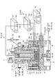
- FIG. 1 is a cross-sectional view schematically showing a configuration example of the filtration device according to the first embodiment.
- FIG. 2 is an explanatory diagram for explaining the operation of the filtration device according to the first embodiment.
- FIG. 3 is a cross-sectional view schematically showing the configurations of the first electrode, the filter medium, and the second electrode.
- FIG. 4 is an electrical equivalent circuit diagram showing the filtration device according to the first embodiment.
- FIG. 5 is a graph showing the relationship between the concentration concentration in the filter chamber and the filtration rate in the solid-liquid separation of chlorella.
- FIG. 6 is a graph showing the relationship between the concentration concentration in the filter chamber and the filtration rate in the solid-liquid separation of sewage activated sludge.
- FIG. 5 is a graph showing the relationship between the concentration concentration in the filter chamber and the filtration rate in the solid-liquid separation of chlorella.
- FIG. 6 is a graph showing the relationship between the concentration concentration in the filter chamber and the filtration rate in the solid-liquid separation of
- FIG. 7 is a cross-sectional view schematically showing a configuration example of the filtration device according to the second embodiment.
- FIG. 8 is an explanatory diagram for explaining the operation of the filtration device according to the second embodiment.
- FIG. 9 is an electrical equivalent circuit diagram showing the filtration device according to the second embodiment.
- FIG. 10 is a schematic view of the filtration device according to the third embodiment.
- FIG. 11 is a schematic diagram of the filtration device according to the modified example of the third embodiment.
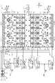
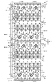
- FIG. 12A is a cross-sectional view schematically showing a configuration example of the filtration system according to the fourth embodiment.
- FIG. 12B is a cross-sectional view schematically showing a configuration example of the filtration system according to the fourth embodiment.
- FIG. 13 is a cross-sectional view schematically showing a configuration example of the first filtration device, the second filtration device, and the third filtration device according to the fourth embodiment.
- FIG. 14 is a schematic view of the first filtration device according to the fourth embodiment.
- FIG. 15 is a schematic view of the second filtration device according to the fourth embodiment.
- FIG. 16 is a schematic view of the third filtration device according to the fourth embodiment.
- FIG. 17 is a schematic diagram schematically showing a configuration example of the filtration system according to the first modification of the fourth embodiment.
- FIG. 18 is a cross-sectional view schematically showing a configuration example of a filtration system according to a first modification of the fourth embodiment.
- FIG. 14 is a schematic view of the first filtration device according to the fourth embodiment.
- FIG. 15 is a schematic view of the second filtration device according to the fourth embodiment.
- FIG. 16 is a schematic view of the third filtration device according to the fourth embodiment.
- FIG. 17 is a schematic diagram
- FIG. 19 is a cross-sectional view schematically showing a configuration example of a filtration system according to a second modification of the fourth embodiment.
- FIG. 20 is a schematic view of the first filtration device, the second filtration device, and the third filtration device according to the third modification of the fourth embodiment.
- FIG. 21 is a schematic diagram of the filtration device according to the fifth embodiment.
- FIG. 22 is a cross-sectional view schematically showing a configuration example of the filtration device according to the sixth embodiment.
- FIG. 23 is a plan view schematically showing a configuration example of the third electrode according to the sixth embodiment.
- FIG. 1 is a cross-sectional view schematically showing a configuration example of the filtration device according to the first embodiment.
- the filtration device 10 according to the first embodiment is an apparatus for separating the first particles 71 from the slurry (stock solution) 70 (target treatment liquid) in which the first particles (particles to be separated) 71 are dispersed in the polar solvent 72.
- the filtration device 10 can be applied to the life science field, the sewage treatment field, the wastewater treatment field, and the like.
- the bio-industry for culturing microorganisms such as cultured cells, microalgae, bacteria, bacteria, and viruses, and the utilization and application of enzymes, proteins, polysaccharides, lipids, etc. produced by cultured microorganisms outside and inside the body. It can be applied to the biopharmaceutical and cosmetics industries, which are the fields, or the beverage industry, which deals with brewing, fermentation, squeezing, beverages, and the like.
- the filtration device 10 is a colloidal particle-based slurry in which surface-charged fine particles are highly dispersed by an electric repulsive action, and can be applied to a concentrated recovery application of colloidal fine particles.
- the filtration device 10 As shown in FIG. 1, the filtration device 10 according to the first embodiment has an upper housing 11, a lid portion 12, a side housing 13, a lower housing 14, and a conductor 15. Further, the filtration device 10 has a first filter chamber 30, a first electrode 31, a second electrode 32, and a second electrode in an internal space surrounded by an upper housing 11, a side housing 13, and a lower housing 14. It has three electrodes 33 and a filter medium 34 (see FIG. 2). The filtration device 10 further has a first power source 51 and a second power source 52 electrically connected to the first electrode 31 and the second electrode 32.
- the upper housing 11 is a columnar member made of an insulating material.
- the side housing 13 is an annular member made of an insulating material and having a through hole. A part of the lower end side of the upper housing 11 is inserted into the through hole of the side housing 13.
- the lower housing 14 is made of an insulating material and supports the side housing 13.
- the lid portion 12 is provided so as to cover the upper surface of the upper housing 11.
- the outer edges of the first electrode 31, the second electrode 32 and the filter medium 34 are sandwiched and fixed between the side housing 13 and the lower housing 14.
- the third electrode 33 is fixed to the lower surface of the upper housing 11 (the surface facing the lower housing 14) by a connecting member (not shown) such as a bolt, and is located inside the through hole of the side housing 13. .
- the conductor 15 is an annular member provided so as to surround the periphery of the side housing 13, and is provided between the side housing 13 and the lower housing 14.
- the lower end side of the conductor 15 is connected to the outer edge of the first electrode 31.
- the upper housing 11 and the conductor 15 are annular members, but the present invention is not limited to this, and other shapes such as a polygonal shape may be used.
- the upper housing 11 and the side housing 13 are fixed by the guide portion 21a. Further, the side housing 13, the lower housing 14, and the conductor 15 are fixed by bolts 21b and 21c. As a result, the position of each housing is fixed, and the first filter chamber is in the space surrounded by the first electrode 31, the second electrode 32, the filter medium 34, the inner wall of the side housing 13, and the third electrode 33. 30 is formed. Further, sealing members such as O-rings are provided at the connection portions between the housings and the electrodes, and the first filter chamber 30 is hermetically provided. Further, the upper housing 11 is provided so that the distance from the lower housing 14 can be adjusted. Thereby, the filtration device 10 can appropriately set the volume of the first filter chamber 30 according to the type and amount of the slurry (stock solution) 70 (hereinafter, may be referred to as a target treatment liquid).
- the upper housing 11 is provided with a slurry supply passage 11a, an exhaust passage 11b, and a through hole 11c.
- One end side of the slurry supply passage 11a opens on the side surface of the upper housing 11 and is connected to the slurry supply unit 16.
- the other end side of the slurry supply passage 11a is opened on the lower surface of the upper housing 11 and is provided so as to be connected to the through hole 33a of the third electrode 33.
- the slurry supply valve 17 has a rod-shaped member 17a provided inside the slurry supply passage 11a, and the rod-shaped member 17a moves in the slurry supply passage 11a in the vertical direction to switch the open / closed state of the through hole 33a. Can be done.
- the through hole 33a is opened by the operation of the slurry supply valve 17, the slurry (stock solution) 70 passes through the slurry supply unit 16, the slurry supply passage 11a, and the through hole 33a of the third electrode 33. It is supplied to the first filter chamber 30. Further, when the through hole 33a is closed by the slurry supply valve 17, the supply of the slurry (stock solution) 70 to the first filter chamber 30 is stopped.
- the valve 19 for exhausting air has a rod-shaped member 19a provided inside the exhaust passage 11b, and the rod-shaped member 19a moves vertically in the exhaust passage 11b, and its tip is inserted and removed from the through hole 33b. Then, the open / closed state of the through hole 33b can be switched.
- the valve 19 for discharging air opens the through hole 33b.
- the air in the first filter chamber 30 is exhausted to the outside through the through hole 33b, the exhaust passage 11b, and the air exhaust portion 18.
- An air discharge valve 18a is connected to the air discharge unit 18.
- the air discharge valve 18a is, for example, a float valve, and is provided so that the air discharge valve 18a is closed when a predetermined amount of air in the first filter chamber 30 is exhausted. After the exhaust in the first filter chamber 30 is completed, the valve 19 for discharging air closes the through hole 33b.
- a predetermined pressure (P) is applied to the slurry (stock solution) 70 filled in the first filter chamber 30 via the slurry supply unit 16 by an external pressurizing pump or the like.
- the predetermined pressure is preferably such that the internal pressurization is, for example, 0.005 MPa to 0.5 MPa, preferably 0.01 MPa to 0.2 MPa, and more preferably 0.05 MPa to 0.2 MPa. ..
- the third electrode 33 is electrically connected to the reference potential GND via the connecting conductor 56.
- the reference potential GND is, for example, a ground potential. However, the present invention is not limited to this, and the reference potential GND may be a predetermined fixed potential different from the ground potential.
- the first electrode 31 is electrically connected to the second terminal 51b of the first power supply 51 via the conductor 15 and the connecting conductor 54. Further, the first electrode 31 is electrically connected to the first terminal 52a of the second power supply 52 via the conductor 15 and the connecting conductor 55a.
- the lower housing 14 is provided with a concave second filter chamber 35, through holes 14a and 14b, and a connection hole 14c.
- the second filter chamber 35 is provided on the upper surface of the lower housing 14 at a position overlapping the first filter chamber 30.
- the through hole 14a connects the second filter chamber 35 and the discharge portion 22.
- the slurry (stock solution) 70 supplied to the first filter chamber 30 the first particles 71 are separated by driving each electrode, and the polar solvent 72 (filter solution 75) from which the first particles 71 are separated is the first electrode. It passes through 31, the filter medium 34 (see FIG. 2) and the second electrode 32, and flows into the second filter chamber 35.
- the filtrate 75 containing the polar solvent 72 from which the first particles 71 are separated is stored in an external storage tank from the discharge portion 22 of the second filter chamber 35 through the through hole 14b.
- connection hole 14c One end side of the connection hole 14c is opened on the upper surface of the lower housing 14, and the outer edge of the second electrode 32 is provided so as to cover the opening 14d of the connection hole 14c. Further, the other end side of the connection hole 14c opens on the side surface of the lower housing 14. A connecting conductor 55b is inserted into the connecting hole 14c, and the connecting conductor 55b and the second electrode 32 are connected to each other. As a result, the second electrode 32 is electrically connected to the second terminal 52b of the second power supply 52.
- the configuration of the filtration device 10 shown in FIG. 1 is merely an example, and the first filter chamber sandwiched between the first electrode 31, the second electrode 32, the filter medium 34 (see FIG. 2), and the third electrode 33. Any configuration may be used as long as 30 can be formed.
- the first electrode 31, the second electrode 32, and the third electrode 33 for example, a titanium alloy, an alumite-treated aluminum alloy, or the like is used, but the method is not limited thereto.
- FIG. 2 is an explanatory diagram for explaining the operation of the filtration device according to the first embodiment.
- FIG. 2 in order to make the explanation easy to understand, the arrangement relationship between the first electrode 31, the second electrode 32, the third electrode 33 and the filter medium 34, and the first filter chamber 30 and the second filter chamber 35 is schematically shown. Shown.
- the first electrode 31 and the second electrode 32 are, for example, mesh-shaped electrodes having openings.
- the first electrode 31 has a plurality of conductive thin wires 31a, and a plurality of first openings 31b are provided between the plurality of conductive thin wires 31a.
- the second electrode 32 has a plurality of conductive thin wires 32a, and a plurality of second openings 32b are provided between the plurality of conductive thin wires 32a.
- the second electrode 32 is provided so as to face one surface (lower surface) of the first electrode 31 via the filter medium 34.
- the filter medium 34 is provided between the first electrode 31 and the second electrode 32.
- the first electrode 31 and the second electrode 32 are provided in direct contact with the filter medium 34.
- the plurality of conductive thin wires 31a and the plurality of conductive thin wires 32a may be metal or carbon fibers.
- the first electrode 31 and the second electrode 32 are not limited to the configuration in which they are in direct contact with the filter medium 34, and may be arranged with a gap between the first electrode 31 and the second electrode 32.
- the filter medium 34 is formed by providing a plurality of openings 34b on the filtration membrane 34a.
- the filter medium 34 for example, a microfiltration membrane (MF membrane (Microfiltration Membrane)), an ultrafiltration membrane (UF membrane (Ultrafiltration Membrane)) and the like are used.
- the filter medium 34 is formed of an insulating material such as a resin material.
- the first opening 31b of the first electrode 31, the second opening 32b of the second electrode 32, and the opening 34b of the filter medium 34 are shown to have the same size, but they are schematically shown for the sake of explanation. As shown, the sizes of the first opening 31b, the second opening 32b, and the opening 34b may be different.
- FIG. 3 is a cross-sectional view schematically showing the configurations of the first electrode, the filter medium, and the second electrode.
- the diameter D3 of the opening 34b provided in the filter medium 34 is smaller than the diameter D1 of the first opening 31b of the first electrode 31, and the diameter of the second opening 32b of the second electrode 32. Smaller than D2.
- the arrangement pitch of the plurality of conductive thin wires 31a, the arrangement pitch of the plurality of conductive thin wires 32a, and the arrangement pitch of the filtration membrane 34a are provided differently from each other.
- the diameter D1 of the first opening 31b of the first electrode 31 is 0.5 ⁇ m or more and 500 ⁇ m or less, for example, about 70 ⁇ m.
- the diameter D2 of the second opening 32b of the second electrode 32 is 0.5 ⁇ m or more and 1000 ⁇ m or less, for example, about 100 ⁇ m.
- the diameter D3 of the plurality of openings 34b provided on the filter medium 34 is 0.1 ⁇ m or more and 100 ⁇ m or less, more preferably 1 ⁇ m or more and 7 ⁇ m or less.
- the diameter D1 of the first opening 31b of the first electrode 31 is smaller than the diameter D2 of the second opening 32b of the second electrode 32.
- the present invention is not limited to this, and the diameter D1 of the first opening 31b of the first electrode 31 may be formed to have the same size as the diameter D2 of the second opening 32b of the second electrode 32.
- the opening 34b of the filter medium 34 is provided non-superimposed on the plurality of conductive thin wires 31a and the plurality of conductive thin wires 32a at least in the region overlapping the first opening 31b and the second opening 32b.
- the distance between the first electrode 31 and the second electrode 32 is defined by the thickness of the filter medium 34.
- the third electrode 33 is a plate-shaped member, and is provided so as to face the other surface (upper surface) of the first electrode 31 with the first filter chamber 30 interposed therebetween.
- the through holes 33a and 33b and the recess 33c (see FIG. 1) of the third electrode 33 are not shown.
- the first filter chamber 30 is provided in contact with the other surface (upper surface) of the first electrode 31.
- the slurry (stock solution) 70 containing the first particles 71 to be separated and the polar solvent 72 is supplied to the first filter chamber 30.
- the first particles 71 are, for example, biomass particles or colloidal particles, and the surface of the particles is negatively charged.
- the first particle 71 is chlorella, microalgae spirulina, colloidal silica, Escherichia coli, sewage activated sludge, or the like.
- the diameter of the first particle 71 varies depending on the technical field to which it is applied and the type of separation target, but is 5 nm or more and 2000 ⁇ m or less, for example, 20 nm or more and 500 ⁇ m or less.
- the polar solvent 72 in which the first particles 71 are dispersed is water, and the water molecules 73 are positively charged. As a result, the slurry (stock solution) 70 is in an electrically equilibrium state as a whole.
- the polar solvent 72 is not limited to water, and may be, for example, alcohol or the like. That is, the polar solvent 72 may be a polar solvent.
- the slurry (stock solution) 70 contains a second particle 74 such as a chromoprotein.
- the second particle 74 is charged with the same polarity (minus) as the first particle 71, and has a smaller particle size than the first particle 71.
- the second particle 74 is, for example, 10 nm or more and 300 nm or less, for example, about 30 nm.
- the second particle 74 may not be present in the slurry 70.
- the first power supply 51 supplies the first electrode 31 with a first potential V1 having the same polarity as that of the first particle 71.
- the first potential V1 is, for example, ⁇ 60 V.
- the second power source 52 supplies the second electrode 32 with a second potential V2 having the same polarity as that of the first particle 71 and having an absolute value larger than the absolute value of the first potential V1.
- the second potential V2 is, for example, ⁇ 70 V.
- the third electrode 33 is connected to the reference potential GND.
- the reference potential GND is the ground potential as described above, ideally 0V.
- the reference potential GND supplied to the third electrode 33 is not limited to 0V, and may be a predetermined fixed potential.
- the first potential V1 and the second potential V2 can be set in an absolute value in the range of 1 mV or more and 1000 V or less.
- FIG. 4 is an electrical equivalent circuit diagram showing the filtration device according to the first embodiment.
- the first power supply 51 is a constant voltage source
- the second power supply 52 is a constant current source.
- the resistance component R1 and the capacitance component C are connected in parallel between the first electrode 31 and the second electrode 32.
- the resistance component R1 and the capacitance component C are components equivalently represented by the filter medium 34 provided with a large number of openings 34b.
- the resistance component R2 is connected between the first electrode 31 and the third electrode 33.
- the resistance component R2 is a resistance component equivalently represented by the slurry (stock solution) 70 of the first filter chamber 30.
- the second power supply 52 may be a constant voltage power supply or a constant current power supply.
- the resistance component R1 of the filter medium 34 and the resistance component R2 of the first filter chamber 30 vary depending on the filtration state of the filtration device 10.
- the second potential V2 changes accordingly.
- the second potential V2 has the same polarity as the polarity of the first particle 71, and maintains a value larger than the absolute value of the first potential V1.
- q1 and q2 are electric charges, and s is the distance between the electric charges. That is, the smaller the distance s, the larger the Coulomb force F acts on the first particle 71.
- the repulsive force F1 generated in the negatively charged first particle 71 acts in the direction indicated by the arrow, that is, in the direction away from the first electrode 31 and closer to the third electrode 33.
- the negatively charged first particle 71 moves to the third electrode 33 side by electrophoresis.
- the filtration device 10 can prevent the first particles 71 from accumulating on the surface of the first electrode 31 and the surface of the filter medium 34 to form a cake layer. That is, it is possible to suppress an increase in the filtration resistance of the opening 34b of the filter medium 34.
- the positively charged water molecule 73 generates an attractive force with the first electrode 31.
- the attractive force F2 acting on the positively charged water molecule 73 acts in the direction indicated by the arrow, that is, in the direction from the third electrode 33 toward the first electrode 31.
- the positively charged water molecule 73 moves to the first electrode 31 side.
- the electric field of the barrier from the first electrode 31 to the second electrode 32 (electric field of the electric field barrier) so as to penetrate the filter medium 34 in the thickness direction due to the potential difference between the first electrode 31 and the second electrode 32.
- E) one-dot chain line in FIG. 2 is formed.
- the water molecule 73 that has moved to the first electrode 31 side receives a force by the electric field, is pulled toward the second electrode 32 side, and passes through the filter medium 34. As the water molecule 73 moves, the surrounding water molecule 73 is also dragged toward the second electrode 32, and an electroosmotic flow is formed. As a result, the polar solvent 72 (filter solution 75) containing the positively charged water molecule 73 flows into the second filter chamber 35. As described above, the first particle 71 is separated from the first electrode 31 by electrophoresis, and the polar solvent 72 (filter liquid 75) from which the first particle 71 is separated is discharged, so that the first particle 71 is separated. The concentration of the first particle 71 of the slurry (stock solution) 70 in the chamber 30 can be increased.
- the filtration device 10 applies the first particle 71 between the first electrode 31 and the third electrode 33 by the Coulomb force F (repulsive force generated between the first particle 71 and the first electrode 31).
- the Coulomb force F pulsesive force generated between the first particle 71 and the first electrode 31.
- the surface of the first electrode 31 and the surface of the filter medium 34 are compared with the method of simply applying pressure to the slurry (stock solution) 70 to separate the first particles 71 having a particle size larger than the opening 34b of the filter medium 34.
- the formation of a cake layer can be suppressed, and the filtration rate can be improved several times to ten times or more.
- the first charge of the slurry (stock solution) 70 in the first filter chamber 30 is positively charged as compared with the method of simply applying pressure to the slurry (stock solution) 70.
- the enrichment of the particles 71 can be increased.
- the frequency of cleaning and replacement of the filter medium 34 can be reduced, and the slurry (stock solution) 70 can be efficiently used. Filtration can be performed.
- the filtration device 10 can be miniaturized.
- the concentrated slurry in which the concentration of the first particles 71 is increased in the first filter chamber 30 is separately and appropriately discharged from the first filter chamber 30.
- the particle level (particle diameter) passing through the filter medium 34 can also be controlled.
- the particle size to be separated can be changed up to the equivalent of an outer filtration membrane (UF membrane) or a nanofiltration membrane (NF membrane).
- the ultrafiltration membrane (UF membrane) is a filtration membrane having an opening diameter of 10 nm or more and 100 nm or less.
- the nanofiltration membrane (NF membrane) is a filtration membrane having an opening diameter of 1 nm or more and 10 nm or less.
- the configuration of the filtration device 10 described above is only an example and can be changed as appropriate.
- the negative electrode filter plate formed by laminating the first electrode 31, the filter medium 34, and the second electrode 32 and the third electrode 33 are arranged so as to face each other in a parallel plate shape.
- the present invention is not limited to this, and the negative electrode filter plate formed by laminating the first electrode 31, the filter medium 34 and the second electrode 32 and the third electrode 33 may each have a curved surface.
- the shape and arrangement of the negative electrode filter plate and the third electrode 33 can be appropriately changed according to the shape and structure of the filtration device 10.
- the concentration of the slurry (stock solution) 70 which is the target treatment liquid supplied to the first filter chamber 30, is not particularly limited and can be changed according to the field to which the filtration device 10 is applied.
- the internal pressure of the first filter chamber 30 is pressurized and is larger than the internal pressure of the second filter chamber 35.
- the internal pressure of the first filter chamber 30 is made relatively larger than the internal pressure of the second filter chamber 35 by applying a negative pressure by vacuuming the internal pressure of the second filter chamber 35 or the like. You may do so.
- first potential V1 and the second potential V2 are appropriately changed according to the type of the first particle 71 to be separated and the required filtration characteristics.
- FIG. 5 is a graph showing the relationship between the concentration concentration in the filter chamber and the filtration rate in the solid-liquid separation of chlorella.
- the coded black circle indicates Example 1
- the coded black square indicates Example 2
- the coded white triangle indicates Comparative Example 1
- the coded white square indicates Comparative Example 2.
- the horizontal axis is the concentration concentration in the filter chamber (wt%), and the vertical axis is the filtration rate (a.u.).
- the filtration rate is the amount (weight) of the polar solvent 72 (filter solution 75) that can pass through the filter medium 34 per hour unit, and in FIG. 5, the value standardized by the filtration rate A3 of Comparative Example 1 is used. Shows.
- the concentration in the filter chamber indicates the mass percent concentration of the first particle 71 with respect to the chlorella culture solution which is the slurry (stock solution) 70 in the first filter chamber 30.
- the first particle 71 to be separated is a chlorella and is negatively charged, and the particle diameter is, for example, about 2 ⁇ m or more and 10 ⁇ m or less.
- the third electrode 33 is used as a reference.
- the case where the potential GND is used is shown.
- a pressure of 0.1 MPa is applied to the slurry (stock solution) 70 in the first filter chamber 30.
- a pressure of 0.02 MPa is applied to the slurry (stock solution) 70 in the first filter chamber 30. That is, in Example 2, the slurry (stock solution) 70 is filtered with a pressure smaller than that of Example 1.
- Comparative Example 1 the slurry (stock solution) 70 is filtered only by pressurizing 0.1 MPa without supplying the first potential V1 and the second potential V2 to the first electrode 31 and the second electrode 32, respectively. ..
- the first potential V1 -60V was applied to the first electrode 31, and the second potential V2 was not applied to the second electrode 32.
- Comparative Example 2 a pressurization of 0.1 MPa is performed. That is, in Comparative Example 2, electrophoresis was performed between the first electrode 31 and the third electrode 33, and electroosmosis was not performed between the first electrode 31 and the second electrode 32.
- both Examples 1 and 2 and Comparative Examples 1 and 2 show a tendency that the filtration rate decreases as the concentration concentration in the filter chamber increases.
- the slurry (stock solution) 70 is concentrated to a concentration concentration in the filter chamber of 7 wt%, it is shown that the filtration rate A1 in Example 1 is 13.6 times higher than the filtration rate A3 in Comparative Example 1. Was done.
- the filtration rate A2 in Example 2 was 3.9 times higher than the filtration rate A3 in Comparative Example 1.
- the filtration rate A4 in Comparative Example 2 is 0.16 times smaller than the filtration rate A3 in Comparative Example 1. That is, as in Comparative Example 2, it is good when the first potential V1 is supplied to the first electrode 31 and only electrophoresis is performed, and electroosmosis is not performed between the first electrode 31 and the second electrode 32. It was shown that it could not be filtered.
- the concentration concentration in the filter chamber can be made larger than that in Comparative Examples 1 and 2.
- Comparative Example 1 it was shown that the concentration concentration in the filter chamber was about 11 wt% at the maximum, whereas in Example 1, the concentration concentration in the filter chamber could be concentrated up to 16 wt% or more.
- the filtration rate could be improved and the maximum was compared with Comparative Examples 1 and 2. It was shown that it is possible to improve the concentration concentration in the filter chamber.
- FIG. 6 is a graph showing the relationship between the concentration concentration in the filter chamber and the filtration rate in the solid-liquid separation of activated sewage sludge.
- the negatively charged first particles 71 to be separated are fine biomass particles contained in the sewage activated sludge.
- the vertical axis of the graph 2 shown in FIG. 6 shows the filtration rate standardized by the filtration rate B4 of Comparative Example 3.
- the coded black circle indicates Example 3
- the coded black square indicates Example 4
- the coded white triangle indicates Example 5
- the coded white square indicates Comparative Example 3.
- the slurry (stock solution) 70 is filtered only by pressurizing 0.1 MPa without supplying the first potential V1 and the second potential V2 to the first electrode 31 and the second electrode 32.
- the alternate long and short dash line C1 shows 1 wt%, which is the maximum concentration concentration when filtered by the membrane separation activated sludge method for comparison.
- the two-dot chain line C2 shows 3.5 wt%, which is the maximum concentration concentration when filtered by a mechanical concentration method using a centrifuge or the like for comparison.
- the filtration rate B1 in Example 3 is compared. It was shown that the filtration rate of Example 3 was 15.7 times higher than that of B4. Similarly, it was shown that the filtration rate B2 in Example 4 was 9.6 times higher than the filtration rate B4 in Comparative Example 3. It was shown that the filtration rate B3 in Example 5 was 5.9 times higher than the filtration rate B4 in Comparative Example 3.
- the maximum concentration concentration of 1 wt% when filtered by the membrane separation activated sludge method and 3.5 wt% of the maximum concentration concentration when filtered by the mechanical concentration method can be concentrated in excess of%.
- the concentration in the filter chamber could be concentrated to 6.5 wt% or more, and in Examples 4 and 5, the concentration in the filter chamber could be concentrated to about 5 wt%.
- the filtration device 10 of the first embodiment is provided with a first electrode 31 provided with a plurality of first openings 31b and a plurality of second openings 32b, and is provided with one surface of the first electrode 31.
- a second electrode 32 provided so as to face the first electrode 32, a filter medium 34 provided between the first electrode 31 and the second electrode 32, and the other surface of the first electrode 31.
- a first filter chamber 30 and a first filter chamber 30 to which a slurry (stock solution) 70 (target treatment solution) containing the first particles 71 to be separated and the polar solvent 72 are supplied are sandwiched between the first filter chamber 30 and the first filter chamber 30.
- the third electrode 33 is connected to the reference potential GND.
- the first particle 71 moves in the direction away from the first electrode 31 by the electrophoretic flow due to the repulsive force (Coulomb force F) generated between the first electrode 31 and the first particle 71. do.
- the repulsive force F Coulomb force F
- the first particles 71 can be separated by electro-osmosis that moves the water molecule 73 by the electric field between the first electrode 31 and the second electrode 32 and passes through the filter medium 34, and the slurry in the first filter chamber 30.
- the concentration of the first particle 71 of the (undiluted solution) 70 can be increased.
- the filtration speed is improved several to 10 times or more as compared with the method of simply applying pressure to the slurry (stock solution) 70 to separate the first particles 71 having a particle size larger than the opening 34b of the filter medium 34.
- the third electrode 33 is connected to the reference potential GND, the filtration device 10 can be downsized as compared with the case where a power source is provided for each of the first electrode 31, the second electrode 32, and the third electrode 33. can.
- the absolute value of the second potential V2 is larger than the absolute value of the first potential V1
- the potential difference between the first potential V1 and the reference potential GND is the same as that of the first potential V1 and the second potential V2. Greater than the potential difference.
- the distance between the first electrode 31 and the third electrode 33 facing each other across the filter medium 34 is larger than the distance between the first electrode 31 and the second electrode 32, the distance is good by electrophoresis.
- the first particle 71 can be moved in a direction away from the first electrode 31.
- the second electrode 32, the filter medium 34, the first electrode 31, the first filter chamber 30, and the third electrode 33 are laminated in this order in the direction perpendicular to the surface of the first electrode 31, and the first electrode
- the distance between 31 and the second electrode 32 is smaller than the distance between the first electrode 31 and the third electrode 33.
- the electric field strength formed between the first electrode 31 and the second electrode 32 can be increased, and the water molecule 73 is moved by electroosmosis to form the first electrode 31 and the second electrode 32.
- the filter medium 34 between them can be passed through well.
- the first power supply 51 is a constant voltage source
- the second power supply 52 is a constant current source
- the Coulomb force F generated between the first electrode 31 and the first particle 71 can be defined by the first potential V1 supplied by the first power supply 51. Further, the electric field strength formed between the first electrode 31 and the second electrode 32 is defined by the current supplied by the second power supply 52 to the first potential V1 supplied by the first power supply 51, which is good. Can be electroosmotic.
- the size (diameter D3) of the opening 34b is smaller than the diameter D1 of the first opening 31b and the diameter D2 of the second opening 32b.
- the opening 34b of the filter medium 34 does not overlap with the conductive thin wires 31a and 32a of the first electrode 31 and the second electrode 32 at least in the region overlapping with the first opening 31b and the second opening 32b. It is provided in. As a result, the water molecule 73 can satisfactorily pass through the opening 34b of the filter medium 34 by electroosmosis.
- FIG. 7 is a cross-sectional view schematically showing a configuration example of the filtration device according to the second embodiment.
- FIG. 8 is an explanatory diagram for explaining the operation of the filtration device according to the second embodiment.
- the same components as those described in the above-described embodiment are designated by the same reference numerals, and duplicated description will be omitted.
- the filtration device 10 has an upper housing 11, a lid portion 12, a side housing 13, a lower housing 14, and a conductor 15. Further, the filtration device 10 has a first filter chamber 30, a first electrode 31, a second electrode 32, and a second electrode in an internal space surrounded by an upper housing 11, a side housing 13, and a lower housing 14. It has three electrodes 33 and a filter medium 34 (see FIG. 8).
- the filtration device 10 further includes a first power source 51, a second power source 52, and a third power source 53 electrically connected to the first electrode 31, the second electrode 32, and the third electrode 33.
- One end side of the through hole 11c opens on the upper surface of the upper housing 11.
- the other end side of the through hole 11c is opened on the lower surface of the upper housing 11 and is provided so as to be connected to the recess 33c of the third electrode 33.
- a connecting conductor 56 is inserted into the through hole 11c, and the connecting conductor 56 and the third electrode 33 are connected by a recess 33c.
- the third electrode 33 is electrically connected to the first terminal 53a of the third power supply 53 via the connecting conductor 56.
- the first electrode 31 is electrically connected to the second terminal 51b of the first power supply 51 via the conductor 15 and the connecting conductor 54. Further, the first electrode 31 is electrically connected to the first terminal 52a of the second power supply 52 via the conductor 15 and the connecting conductor 55a.
- the second terminal 53b of the third power supply 53 and the first terminal 51a of the first power supply 51 are connected to the reference potential GND.
- the reference potential GND is, for example, a ground potential. However, the present invention is not limited to this, and the reference potential GND may be a predetermined fixed potential.
- FIG. 9 is an electrical equivalent circuit diagram showing the filtration device according to the second embodiment.
- the first power supply 51 and the third power supply 53 are constant voltage sources, and the second power supply 52 is a constant current source.
- the resistance component R1 and the capacitance component C are connected in parallel between the first electrode 31 and the second electrode 32.
- the resistance component R1 and the capacitance component C are components equivalently represented by the filter medium 34 provided with a large number of openings 34b.
- the resistance component R2 is connected between the first electrode 31 and the third electrode 33.
- the resistance component R2 is a resistance component equivalently represented by the slurry (stock solution) 70 of the first filter chamber 30.
- the second power supply 52 may be a constant voltage power supply or a constant current power supply.
- the second power source 52 is a constant current source, the resistance component R1 of the filter medium 34 and the resistance component R2 of the first filter chamber 30 change according to the filtration state of the filtration device 10. Accordingly, the second potential V2 changes.
- the second potential V2 has the same polarity as the polarity of the first particle 71, and maintains a value larger than the absolute value of the first potential V1.
- a stronger repulsive force (f1) is generated in the first particle 71 located near the first electrode 31, and a stronger attractive force is generated in the first particle 71 located near the third electrode 33.
- F2 occurs.
- the sum of the repulsive force (f1) and attractive force (f2) vectors F3 generated in the negatively charged first particle 71 acts in the direction indicated by the arrow, that is, in the direction away from the first electrode 31 and closer to the third electrode 33.
- the negatively charged first particle 71 moves to the third electrode 33 side by electrophoresis.
- the filtration device 10 can prevent the first particles 71 from accumulating on the surface of the first electrode 31 and the surface of the filter medium 34 to form a cake layer. That is, it is possible to suppress an increase in the filtration resistance of the opening 34b of the filter medium 34.
- the positively charged water molecule 73 generates an attractive force with the first electrode 31.
- the attractive force F2 acting on the positively charged water molecule 73 acts in the direction indicated by the arrow, that is, in the direction from the third electrode 33 toward the first electrode 31.
- the positively charged water molecule 73 moves to the first electrode 31 side.
- an electric field is formed from the first electrode 31 to the second electrode 32 so as to penetrate the filter medium 34 in the thickness direction due to the potential difference between the first electrode 31 and the second electrode 32.
- the water molecule 73 that has moved to the first electrode 31 side receives a force by the electric field, is pulled toward the second electrode 32 side, and passes through the filter medium 34. With the movement of the positively charged water molecule 73, the uncharged water molecule is also dragged toward the second electrode 32, and an electroosmotic flow is formed. As a result, the polar solvent 72 (filter solution 75) containing the positively charged water molecule 73 flows into the second filter chamber 35. As described above, the first particle 71 is separated from the first electrode 31 by electrophoresis and moved to the third electrode 33 side, and the polar solvent 72 (filter solution 75) from which the first particle 71 is separated is used. By discharging to the second filter chamber 35 side, the concentration of the first particles 71 of the slurry (stock solution) 70 in the first filter chamber 30 can be increased.
- the filtering device 10 applies the first particle 71 between the first electrode 31 and the third electrode 33 by the Coulomb force F (repulsive force generated between the first particle 71 and the first electrode 31).
- the first particle 71 can be separated by combining the moving electrophoresis and the electric permeation in which the water molecule 73 is moved by the electric field between the first electrode 31 and the second electrode 32 and passed through the filter medium 34.
- the first electrode 31 also serves as an electrode for electrophoresis and an electrode for electroosmosis.
- the surface of the first electrode 31 and the surface of the filter medium 34 are compared with the method of simply applying pressure to the slurry (stock solution) 70 to separate the first particles 71 having a particle size larger than the opening 34b of the filter medium 34. It is possible to suppress the formation of a cake layer, and the filtration rate can be improved several times to ten times or more.
- the concentration of the first particle 71 of the slurry (stock solution) 70 in the first filter chamber 30 can be increased as compared with the method of simply applying pressure to the slurry (stock solution) 70. Further, since the formation of the cake layer of the first particles 71 on the surface of the first electrode 31 and the surface of the filter medium 34 is suppressed, the frequency of cleaning and replacement of the filter medium 34 can be reduced, and the slurry can be efficiently replaced. (Undiluted solution) 70 can be filtered. Alternatively, as compared with the case where pressure is simply applied to the slurry (stock solution) 70 to perform filtration, even if the volume of the first filter chamber 30 is reduced and the area of the filter medium 34 is reduced, the slurry (stock solution) 70 is simply reduced. It is possible to achieve the same filtration rate as when pressure is applied to. That is, the filtration device 10 can be miniaturized.
- the particle level (particle diameter) passing through the filter medium 34 can also be controlled.
- the electric field is formed, and the second particles 74 having a particle size (5 nm or more and 2000 ⁇ m or less) smaller than the opening (0.1 ⁇ m or more and 100 ⁇ m or less) 34b of the filter medium 34 can be suppressed from passing through the filter medium 34.
- the ultrafiltration membrane is controlled by the electric field control between the electrodes of the first power supply 51, the second power supply 52, and the third power supply 53.
- the particle size to be separated can be changed to the equivalent of (UF membrane) or nanofiltration membrane (NF membrane).
- the ultrafiltration membrane (UF membrane) is a filtration membrane having an opening diameter of 10 nm or more and 100 nm or less.
- the nanofiltration membrane (NF membrane) is a filtration membrane having an opening diameter of 1 nm or more and 10 nm or less.
- the configuration of the filtration device 10 described above is just an example and can be changed as appropriate.
- the negative electrode filter plate formed by laminating the first electrode 31, the filter medium 34, and the second electrode 32 and the third electrode 33 are arranged so as to face each other in a parallel plate shape.
- the present invention is not limited to this, and the negative electrode filter plate formed by laminating the first electrode 31, the filter medium 34 and the second electrode 32 and the third electrode 33 may each have a curved surface.
- the shape and arrangement of the negative electrode filter plate and the third electrode 33 can be appropriately changed according to the shape and structure of the filtration device 10.
- the concentration of the slurry (stock solution) 70 which is the target treatment liquid supplied to the first filter chamber 30, is not particularly limited and can be changed according to the field to which the filtration device 10 is applied.
- the internal pressure of the first filter chamber 30 is pressurized and is larger than the internal pressure of the second filter chamber 35.
- the internal pressure of the first filter chamber 30 is made relatively larger than the internal pressure of the second filter chamber 35 by applying a negative pressure by vacuuming the internal pressure of the second filter chamber 35 or the like. You may do so.
- the first potential V1, the second potential V2 and the third potential V3 are appropriately changed according to the type of the first particle 71 to be separated and the required filtration characteristics.
- the filtration device 10 of the second embodiment is provided with a first electrode 31 provided with a plurality of first openings 31b and a plurality of second openings 32b provided with one surface of the first electrode 31.
- a second electrode 32 provided so as to face each other, a filter medium 34 provided between the first electrode 31 and the second electrode 32 provided with a plurality of openings 34b, and the other surface of the first electrode 31.
- the first filter chamber 30 is provided in contact with each other and the slurry (stock solution) 70 (target treatment solution) containing the first particles 71 to be separated and the polar solvent 72 is supplied, and the first filter chamber 30 is sandwiched between the first filter chamber 30 and the first filter chamber 30.
- the Coulomb force F generated in the first particle 71 between the first electrode 31 and the third electrode 33 (the repulsive force generated between the first particle 71 and the first electrode 31). ) Moves the first particle 71 in the direction from the first electrode 31 toward the third electrode 33.
- the first particles 71 can be separated by electro-osmosis that moves the water molecule 73 by the electric field between the first electrode 31 and the second electrode 32 and passes through the filter medium 34, and the slurry in the first filter chamber 30.
- the concentration of the first particle 71 of the (undiluted solution) 70 can be increased.
- the filtration speed is improved several to 10 times or more as compared with the method of simply applying pressure to the slurry (stock solution) 70 to separate the first particles 71 having a particle size larger than the opening 34b of the filter medium 34. Can be made to.
- the absolute value of the second potential V2 is larger than the absolute value of the first potential V1
- the potential difference between the first potential V1 and the third potential V3 is the first potential V1 and the second potential V2. Greater than the potential difference of.
- the distance between the first electrode 31 and the third electrode 33 facing each other across the filter medium 34 is larger than the distance between the first electrode 31 and the second electrode 32, the distance is good by electrophoresis.
- the first particle 71 can be moved to the third electrode 33 side.
- the second electrode 32, the filter medium 34, the first electrode 31, the first filter chamber 30, and the third electrode 33 are laminated in this order in the direction perpendicular to the surface of the first electrode 31, and the first electrode
- the distance between 31 and the second electrode 32 is smaller than the distance between the first electrode 31 and the third electrode 33.
- the electric field strength formed between the first electrode 31 and the second electrode 32 can be increased, and the water molecule 73 is moved by electroosmosis to form the first electrode 31 and the second electrode 32.
- the filter medium 34 between them can be passed through well.
- the first power supply 51 and the third power supply 53 are constant voltage sources, and the second power supply 52 is a constant current source.
- the first particle 71 is between the first electrode 31 and the third electrode 33 by the first potential V1 supplied by the first power supply 51 and the third potential V3 supplied by the third power supply 53.
- the Coulomb force F generated in can be specified.
- the electric field strength formed between the first electrode 31 and the second electrode 32 is defined by the current supplied by the second power supply 52 to the first potential V1 supplied by the first power supply 51, which is good. Can be electroosmotic.
- the size (diameter D3) of the opening 34b is smaller than the diameter D1 of the first opening 31b and the diameter D2 of the second opening 32b.
- the opening 34b of the filter medium 34 does not overlap with the conductive thin wires 31a and 32a of the first electrode 31 and the second electrode 32 at least in the region overlapping with the first opening 31b and the second opening 32b. It is provided in. As a result, the water molecule 73 can satisfactorily pass through the opening 34b of the filter medium 34 by electroosmosis.
- the negatively charged first particles 71 are in a range of several nm or more and several ⁇ m or less from the first electrode 31 due to the combined effect of electrophoresis and the electric field barrier E. It is separated from the first electrode 31. Further, by discharging the polar solvent 72 (filter solution 75) from which the first particle 71 is separated, the concentration of the first particle 71 of the slurry (stock solution) 70 in the first filter chamber 30 is increased, and the first filter is used. A concentrated slurry is formed in the chamber 30.
- the concentrated slurry in which the negatively charged first particles 71 are concentrated can be discharged from the concentrated liquid discharge port (not shown) provided in the first filter chamber 30.
- a stronger repulsive force is generated in the first particle 71 at a position close to the first electrode 31 as compared with the filtration device 10 of the first embodiment.
- a stronger attractive force is generated in the first particle 71 at a position closer to the third electrode 33 as compared with the filtration device 10 of the first embodiment.
- the sum of the vectors of the repulsive force (see F1 in FIG. 2) and the attractive force (f2) generated in the negatively charged first particle 71 is the repulsive force F1 generated in the first particle in the filtering device 10 of the first embodiment. Comparing the force relationships, the relationship is F1 ⁇ F3, and the sum of the repulsive force and attractive force vectors generated in the negatively charged first particle 71 is F3, and the force that moves to the third electrode 33 side by electrophoresis is large.
- the filtration device 10 of the second embodiment has the third electrode 33 rather than the filtration device 10 of the first embodiment, and by applying a predetermined potential to the third electrode 33, the first electrode 31 and the first electrode 31 Due to the sum of the repulsive force and attractive force vectors F3 acting between the two, the effect of separating from the first electrode 31 in the range of several nm to several ⁇ m is increased. As a result, the time when the filtration resistance of the filter medium 34 increases is delayed. Therefore, the state in which the filtration resistance of the filter medium 34 is small continues for a long period of time, and the filtration rate is further improved.
- FIG. 10 is a schematic view of the filtration device according to the third embodiment.
- the same components as those described in the above-described embodiment are designated by the same reference numerals, and duplicated description will be omitted.
- the filtration device 10 according to the third embodiment is a device that separates the first particles 71 from the slurry (stock solution) 70 (target treatment liquid) in which the first particles 71 are dispersed in the polar solvent 72.
- the filtration device 10 includes a housing 20, four filtration units 100 arranged inside the housing 20, a second filter chamber 35, and two first power supplies. It includes 51, two second power supplies 52, and two third power supplies 53.
- the four filtration units 100 include a filtration unit 101, a filtration unit 102, a filtration unit 105, and a filtration unit 106.
- the filtration unit 101 and the filtration unit 102 are arranged side by side in one direction X.
- the filtration unit 105 and the filtration unit 106 are arranged side by side in one direction X.
- the filtration unit 101 and the filtration unit 105 are arranged side by side in the other direction Y orthogonal to the one direction X.
- the filtration unit 102 and the filtration unit 106 are arranged side by side in the other direction Y.
- Each filtration unit 100 has a first filter chamber 30, a first electrode 31, a second electrode 32, a third electrode 33, and a filter medium 34.
- the first filter chamber 30 is a space surrounded by the inner wall of the housing 20, the first electrode 31, and the third electrode 33.
- the first electrode 31 and the second electrode 32 are mesh-shaped electrodes. Specifically, the first electrode 31 has a plurality of conductive thin wires 31a, and a plurality of first openings 31b are provided between the plurality of conductive thin wires 31a.
- the second electrode 32 has a plurality of conductive thin wires 32a, and a plurality of second openings 32b are provided between the plurality of conductive thin wires 32a.
- the second electrode 32 is provided so as to face one surface (lower surface) of the first electrode 31 via the filter medium 34. In other words, the filter medium 34 is provided between the first electrode 31 and the second electrode 32.
- the first electrode 31 and the second electrode 32 are provided in direct contact with the filter medium 34.
- the plurality of conductive thin wires 31a and the plurality of conductive thin wires 32a are not particularly limited as long as they are conductive materials, and may be, for example, metal or carbon fiber.
- the first electrode 31 and the second electrode 32 are not limited to the configuration in which they are in direct contact with the filter medium 34, and may be arranged with a gap between the first electrode 31 and the second electrode 32.
- the third electrode 33 is a plate-shaped member, and is provided so as to face the other surface (upper surface) of the first electrode 31 with the first filter chamber 30 interposed therebetween.
- the first electrode 31, the second electrode 32, the third electrode 33, and the filter medium 34 included in one filtration unit 100 are shared with the adjacent filtration units 100 in the other direction Y.
- one first electrode 31, one second electrode 32, one third electrode 33, and one filter medium 34 are adjacent filtration units 100 (a set of filtration unit 101 and filtration unit 105) in the other direction Y.
- the set of filtration unit 102 and filtration unit 106 are adjacent filtration units 100 (a set of filtration unit 101 and filtration unit 105) in the other direction Y.
- a plurality of electrodes are arranged in the order of the third electrode 33, the first electrode 31, and the second electrode 32.
- a plurality of electrodes are arranged in the order of the second electrode 32, the first electrode 31, and the third electrode 33.
- the first opening 31b of the first electrode 31, the second opening 32b of the second electrode 32, and the opening 34b of the filter medium 34 are shown to have the same size, but are shown schematically for the sake of explanation.
- the sizes of the first opening 31b, the second opening 32b, and the opening 34b may be different.
- the configuration of the filtration unit 100 shown in FIG. 10 is merely an example, and it is possible to form the first filter chamber 30 sandwiched between the first electrode 31, the second electrode 32, the filter medium 34, and the third electrode 33. It may have such a configuration.
- the first electrode 31 is electrically connected to the second terminal 51b of the first power supply 51. Further, the first electrode 31 is electrically connected to the first terminal 52a of the second power supply 52.
- the second electrode 32 is electrically connected to the second terminal 52b of the second power supply 52.
- the third electrode 33 is electrically connected to the first terminal 53a of the third power supply 53.
- the second terminal 53b of the third power supply 53 and the first terminal 51a of the first power supply 51 are connected to the reference potential GND.
- the reference potential GND is, for example, a ground potential. However, the present invention is not limited to this, and the reference potential GND may be a predetermined fixed potential.
- FIG. 9 is an electrical equivalent circuit diagram showing the filtration unit according to the third embodiment.
- the first power source 51 supplies the first electrode 31 with a first potential V1 having the same polarity as that of the first particle 71.
- the first potential V1 is, for example, ⁇ 30 V.
- the second power source 52 supplies the second electrode 32 with a second potential V2 having the same polarity as that of the first particle 71 and having an absolute value larger than the absolute value of the first potential V1.
- the second potential V2 is, for example, ⁇ 40 V.
- the third power source 53 supplies the third electrode 33 with a third potential V3 having a polarity different from that of the first particle 71.
- the third potential V3 is, for example, + 30V.
- the first potential V1, the second potential V2, and the third potential V3 can be set in an absolute value in the range of 1 mV or more and 1000 V or less.
- the first power supply 51 and the third power supply 53 are constant voltage sources, and the second power supply 52 is a constant current source.
- the resistance component R1 and the capacitance component C are connected in parallel between the first electrode 31 and the second electrode 32.
- the resistance component R1 and the capacitance component C are components equivalently represented by the filter medium 34 provided with a large number of openings 34b.
- the resistance component R2 is connected between the first electrode 31 and the third electrode 33.
- the resistance component R2 is a resistance component equivalently represented by the slurry (stock solution) 70 of the first filter chamber 30.
- the second power supply 52 may be a constant voltage power supply or a constant current power supply.
- the resistance component R1 of the filter medium 34 and the resistance component R2 of the first filter chamber 30 change according to the filtration state of the filtration device 10. Accordingly, the second potential V2 changes.
- the second potential V2 has the same polarity as the polarity of the first particle 71, and maintains a value larger than the absolute value of the first potential V1.
- the slurry supply unit 81, the first discharge unit 83, and the second discharge unit 85 are connected to the housing 20.
- the slurry supply unit 81 is a pipe connected to the tank 80 in which the slurry (stock solution) 70 is stored via the pressurizing device 316.
- the slurry supply unit 81 is connected to the first filter chamber 30.
- the pressurizing device 316 is, for example, a pressurizing pump.
- the slurry supply unit 81 supplies the slurry (stock solution) 70 containing the first particles 71 to be separated and the polar solvent 72 to the first filter chamber 30 by the pressurizing device 316.
- the first discharge unit 83 is a pipe for discharging a part of the slurry (stock solution) 70 from the first filter chamber 30.
- the first discharge unit 83 is connected to the first filter chamber 30.
- the first discharge unit 83 is provided at a position different from that of the slurry supply unit 81.
- the first discharge unit 83 includes a valve 19. When the valve 19 is opened, the first discharge unit 83 discharges a part of the concentrated slurry 70A in which the slurry (stock solution) 70 introduced into the first filter chamber 30 is concentrated.
- the second discharge unit 85 is a pipe for discharging the filtrate 75 in the second filter chamber 35 from the second filter chamber 35.
- the second discharge unit 85 is connected to the decompression device 317.
- the decompression device 317 is, for example, a vacuum pump.
- the second filter chamber 35 is a space surrounded by the inner wall of the housing 20 and the two second electrodes 32.
- the second filter chamber 35 is arranged between two filtration units 100 arranged in one direction X.
- the sum of the repulsive force and attractive force vectors F3 acts on the first particle 71 of the slurry (stock solution) 70 by driving each electrode, so that a concentration gradient occurs in the dispersion state of the first particle 71.
- the slurry (stock solution) 70 from which the first particles 71 are separated sequentially passes through the first electrode 31, the filter medium 34, and the second electrode 32, and flows into the second filter chamber 35.
- the filtrate 75 discharged to the second filter chamber 35 is stored in an external storage tank via the second discharge section 85.
- the first particles 71 of the separation target in the slurry are, for example, biomass particles or colloidal particles, and the particle surface is negatively charged.
- the first particle 71 is chlorella, microalgae spirulina, colloidal silica, Escherichia coli, sewage activated sludge, or the like.
- the diameter of the first particle 71 varies depending on the technical field to which it is applied and the type of separation target, but is 5 nm or more and 2000 ⁇ m or less, for example, 20 nm or more and 500 ⁇ m or less.
- the polar solvent 72 in which the first particles 71 are dispersed is water in the present embodiment, and the water molecule 73 is positively charged. As a result, the slurry (stock solution) 70 is in an electrically equilibrium state as a whole.
- the polar solvent 72 is not limited to water, but may be alcohol or the like. That is, the polar solvent 72 may be a polar solvent.
- the slurry (stock solution) 70 further contains a second particle 74 such as a dye protein.
- the second particle 74 is charged with the same polarity (minus) as the first particle 71, and has a smaller particle size than the first particle 71.
- the second particle 74 is 10 nm or more and 300 nm or less, for example, about 30 nm. The second particle 74 may not be present in the slurry.
- the slurry (stock solution) 70 When the slurry (stock solution) 70 is supplied to the first filter chamber 30, it is between the negatively charged first particles 71 and the first electrode 31 based on Coulomb's law represented by the above formula (1). Repulsive force is generated in. Further, an attractive force is generated between the negatively charged first particle 71 and the third electrode 33.
- a stronger repulsive force is generated in the first particle 71 located near the first electrode 31, whereas a stronger repulsive force is generated in the first particle 71 located near the third electrode 33. Attraction is generated.
- the sum of the repulsive force and attractive force vectors F3 generated in the first particle 71 acts in the direction indicated by the arrow, that is, in the direction away from the first electrode 31 and closer to the third electrode 33.
- the negatively charged first particle 71 moves to the third electrode 33 side by electrophoresis.
- the filtration device 10 can prevent the first particles 71 from accumulating on the surface of the first electrode 31 and the surface of the filter medium 34 to form a cake layer. That is, it is possible to suppress an increase in the filtration resistance of the opening 34b of the filter medium 34.
- the positively charged water molecule 73 generates an attractive force with the first electrode 31.
- the attractive force F2 acting on the positively charged water molecule 73 acts in the direction indicated by the arrow, that is, in the direction from the third electrode 33 toward the first electrode 31.
- the positively charged water molecule 73 moves to the first electrode 31 side.
- an electric field E from the first electrode 31 to the second electrode 32 is formed so as to penetrate the filter medium 34 in the thickness direction due to the potential difference between the first electrode 31 and the second electrode 32.
- the positively charged water molecule 73 that has moved to the first electrode 31 side receives a force by an electric field and is pulled toward the second electrode 32 side by the attractive force F2 that acts on the water molecule 73 and passes through the filter medium 34. With the movement of the positively charged water molecule 73, the uncharged water molecule is also dragged toward the second electrode 32, and an electroosmotic flow is formed. As a result, the polar solvent 72 containing the positively charged water molecule 73 flows into the second filter chamber 35. As described above, the first particle 71 is separated from the first electrode 31 by electrophoresis and moved to the third electrode 33 side, and the filtrate 75 from which the first particle 71 is separated is on the second filter chamber 35 side. The concentration of the first particles 71 of the slurry (stock solution) 70 in the first filter chamber 30 can be increased.
- the filtering device 10 applies the first particle 71 between the first electrode 31 and the third electrode 33 by the Coulomb force F (repulsive force generated between the first particle 71 and the first electrode 31).
- the first particle 71 can be separated by combining the moving electrophoresis and the electric permeation in which the water molecule 73 is moved by the electric field between the first electrode 31 and the second electrode 32 and passed through the filter medium 34.
- the first electrode 31 also serves as an electrode for electrophoresis and an electrode for electroosmosis.
- the surface of the first electrode 31 and the surface of the filter medium 34 are compared with the method of simply applying pressure to the slurry (stock solution) 70 to separate the first particles 71 having a particle size larger than the opening 34b of the filter medium 34. It is possible to suppress the formation of a cake layer, and the filtration rate can be improved several times to ten times or more.
- the concentration of the first particle 71 of the slurry (stock solution) 70 in the first filter chamber 30 can be increased as compared with the method of simply applying pressure to the slurry (stock solution) 70.
- the frequency of cleaning and replacement of the filter medium 34 can be reduced, and the slurry (stock solution) 70 can be efficiently filtered.
- the filtration speed is about the same as the conventional one. Can be realized. That is, the filtration device 10 can be miniaturized.
- the particle level (particle diameter) passing through the filter medium 34 can also be controlled.
- the electric field is formed, and it is possible to prevent the second particles 74 having a particle size smaller than the opening 34b of the filter medium 34 from passing through the filter medium 34.
- the ultrafiltration membrane is controlled by the electric field control between the electrodes of the first power supply 51, the second power supply 52, and the third power supply 53.
- the particle size to be separated can be changed to the equivalent of (UF membrane) or nanofiltration membrane (NF membrane).
- the ultrafiltration membrane (UF membrane) is a filtration membrane having an opening diameter of 10 nm or more and 100 nm or less.
- the nanofiltration membrane (NF membrane) is a filtration membrane having an opening diameter of 1 nm or more and 10 nm or less.
- the configuration of the filtration device 10 described above is only an example and can be changed as appropriate.
- the negative electrode filter plate formed by laminating the first electrode 31, the filter medium 34, and the second electrode 32 and the third electrode 33 are arranged so as to face each other in a parallel plate shape.
- the present invention is not limited to this, and the negative electrode filter plate formed by laminating the first electrode 31, the filter medium 34 and the second electrode 32 and the third electrode 33 may each have a curved surface.
- the shape and arrangement of the negative electrode filter plate and the third electrode 33 can be appropriately changed according to the shape and structure of the filtration device 10.
- the concentration of the slurry (stock solution) 70 which is the target treatment liquid supplied to the first filter chamber 30, is not particularly limited and can be changed according to the field to which the filtration device 10 is applied.
- the internal pressure of the first filter chamber 30 is pressurized and is larger than the internal pressure of the second filter chamber 35.
- the internal pressure of the first filter chamber 30 is made relatively larger than the internal pressure of the second filter chamber 35 by applying a negative pressure by vacuuming the internal pressure of the second filter chamber 35 or the like. You may do so.
- the plurality of filtration units 100 of the third embodiment may be arranged side by side in a direction orthogonal to both the one direction X and the other direction Y (the depth direction of the paper surface in FIG. 10). That is, the plurality of filtration units 100 may be arranged three-dimensionally side by side.
- each filtration unit 100 may be partitioned by a partition wall between the units, or may be a virtual partition wall.
- the internal slurry may be moved by a member (for example, an opening, a connecting passage, etc.) communicating with each unit.
- the filtration device 10 does not necessarily have to include two first power sources 51, two second power sources 52, and two third power sources 53.
- the number of power supplies that are constant voltage power supplies may be one.
- the number of the first power supply 51 and the third power supply 53 may be one.
- one first power source 51 is connected to the plurality of first electrodes 31, and one third power source 53 is connected to the plurality of third electrodes 33.
- the first potential V1, the second potential V2 and the third potential V3 are appropriately changed according to the type of the first particle 71 to be separated and the required filtration characteristics.
- the filtration device 10 does not have to be provided with the third power source 53.
- the third electrode 33 is connected to, for example, the reference potential GND.
- the filtration device 10 can be downsized as compared with the case where a power source is provided for each of the first electrode 31, the second electrode 32, and the third electrode 33.
- the filtration device 10 does not necessarily have to include both the pressurizing device 316 and the depressurizing device 317.
- the filtration device 10 may include only one of the pressurizing device 316 and the depressurizing device 317.
- the filtration device 10 of the present embodiment has a plurality of filtration units 100.
- the filtration unit 100 includes a first electrode 31, a second electrode 32, a filter medium 34, a first filter chamber 30, and a third electrode 33.
- the first electrode 31 is provided with a plurality of first openings 31b.
- the second electrode 32 is provided with a plurality of second openings 32b and is provided so as to face one surface of the first electrode 31.
- the filter medium 34 is provided with a plurality of openings 34b and is provided between the first electrode 31 and the second electrode 32.
- the first filter chamber 30 is provided in contact with the other surface of the first electrode 31.
- the third electrode 33 is provided in the first filter chamber 30 and faces the first electrode 31.
- Two filtration units 100 are arranged side by side in one direction X.
- the filtration device 10 includes a second filter chamber 35 provided between the two second electrodes 32.
- the Coulomb force F generated in the first particle 71 between the first electrode 31 and the third electrode 33 (between the first particle 71 and the first electrode 31).
- the first particle 71 moves in the direction from the first electrode 31 toward the third electrode 33 due to the repulsive force generated in the above.
- electrophoresis it is possible to suppress the formation of a cake layer on the surface of the first electrode 31 and the surface of the filter medium 34.
- the first particles 71 can be separated by electro-osmosis that moves the water molecule 73 by the electric field between the first electrode 31 and the second electrode 32 and permeates the filter medium 34, and the slurry in the first filter chamber 30.
- the concentration of the first particle 71 of the (undiluted solution) 70 can be increased.
- the filtration speed is improved several to 10 times or more as compared with the method of simply applying pressure to the slurry (stock solution) 70 to separate the first particles 71 having a particle size larger than the opening 34b of the filter medium 34.
- the filtration device 10 can easily adjust the amount of the slurry (stock solution) 70 in the first filter chamber 30.
- a plurality of electrodes are arranged in the order of the third electrode 33, the first electrode 31, and the second electrode 32 in one direction X.
- a plurality of electrodes are arranged in the order of the second electrode 32, the first electrode 31, and the third electrode 33 in one direction X.
- one filtration unit 100 (filtration unit 101) and the other filtration unit 100 (filtration unit 102) can share one second filter chamber 35. Therefore, the filtration device 10 can be downsized as compared with the case where one second filter chamber 35 is provided in one filtration unit 100.
- the first filter chamber 30 is provided at a position different from the slurry supply unit 81 for supplying the target treatment liquid (slurry (stock solution) 70) and the slurry supply unit 81, and is provided at a different position from the target treatment.
- a first discharge unit 83 for discharging a part of the liquid (a part of the slurry (stock solution) 70 or a part of the concentrated slurry 70A) is connected.
- the filtration device 10 can easily adjust the amount of the target treatment liquid (slurry (stock solution) 70) in the first filter chamber 30.
- two filtration units 100 are arranged side by side in the other direction Y orthogonal to one direction X.
- the filtration device 10 can increase the amount of the slurry (stock solution) 70 that can be filtered per unit time. Further, the replacement of the filtration unit 100 is easier than in the case of increasing the size of one filtration unit 100.
- a second discharge unit 85 for discharging the filtrate 75 in the second filter chamber 35 is connected to the second filter chamber 35.
- the filtration device 10 can easily convey the filtrate 75 to a storage tank or the like outside the second filter chamber 35.
- the absolute value of the second potential V2 of the second electrode 32 is larger than the absolute value of the first potential V1 of the first electrode 31.
- the potential difference between the first potential V1 and the third potential V3 of the third electrode 33 is larger than the potential difference between the first potential V1 and the second potential V2.
- the filtration device 10 may include a first power source 51 which is a constant voltage power source, and one first power source 51 may supply a first potential V1 to a plurality of first electrodes 31.
- the second power source 52 of the filtration device 10 is a constant voltage power source
- the second potential V2 may be supplied from one second power source 52 to the plurality of second electrodes 32.
- the filtration device 10 includes a third power source 53 which is a constant voltage power source, and one third power source 53 may supply a third potential V3 to a plurality of third electrodes 33.
- the filtration device 10 can simplify the power supply device and reduce the manufacturing cost.
- FIG. 11 is a schematic diagram of the filtration device according to the modified example of the third embodiment.
- the same components as those described in the above-described embodiment are designated by the same reference numerals, and duplicated description will be omitted.
- the filtration device 10A according to the modified example includes eight filtration units 100 and two second filter chambers 35. Since it is the same as FIG. 10, although not shown, the filtration device 10A according to the modified example includes four first power supplies 51, four second power supplies 52, and four third power supplies 53.
- the eight filtration units 100 include a filtration unit 101, a filtration unit 102, a filtration unit 103, a filtration unit 104, a filtration unit 105, a filtration unit 106, a filtration unit 107, and a filtration unit 108.
- the filtration unit 101, the filtration unit 102, the filtration unit 103, and the filtration unit 104 are arranged side by side in one direction X.
- the filtration unit 105, the filtration unit 106, the filtration unit 107, and the filtration unit 108 are arranged side by side in one direction X.
- the filtration unit 103 and the filtration unit 107 are arranged side by side in the other direction Y.
- the filtration unit 104 and the filtration unit 108 are arranged side by side in the other direction Y.
- the first electrode 31, the second electrode 32, the third electrode 33, and the filter medium 34 included in one filtration unit 100 are shared with the adjacent filtration units 100 in the other direction Y.
- one first electrode 31, one second electrode 32, one third electrode 33, and one filter medium 34 are adjacent filtration units 100 (a set of filtration unit 103 and filtration unit 107) in the other direction Y. And is shared by the set of filtration unit 104 and filtration unit 108).
- a plurality of electrodes are arranged in the order of the third electrode 33, the first electrode 31, and the second electrode 32.
- a plurality of electrodes are arranged in the order of the second electrode 32, the first electrode 31, and the third electrode 33.
- the third electrode 33 included in the filtration unit 102 is shared with the adjacent filtration units 103 in one direction X.
- the third electrode 33 included in the filtration unit 106 is shared with the adjacent filtration units 107 in one direction X.
- the filtration unit 100 (the set of the filtration unit 102 and the filtration unit 103, and the set of the filtration unit 106 and the filtration unit 107) adjacent to each other in the one direction X. ) Is partitioned by the third electrode 33 shared by.
- the device configuration can be made compact.
- the four filtration units 100 do not necessarily have to be arranged in one direction X.
- the number of filtration units 100 arranged in one direction X may be three or five or more.
- the third electrode 33 arranged between the two arranged first filter chambers 30 in one direction X does not necessarily have to be shared by the two filtration units 100. That is, two third electrodes 33 isolated from each other may be arranged between the two arranged first filter chambers 30 in one direction X.
- the plurality of filtration units 100 may be arranged side by side in a direction orthogonal to both the one direction X and the other direction Y (the depth direction of the paper surface in FIG. 11). That is, the plurality of filtration units 100 may be arranged three-dimensionally side by side.
- the filtration device 10A does not necessarily have to include four first power sources 51, four second power sources 52, and four third power sources 53.
- the number of power supplies that are constant voltage power supplies may be one.
- the number of the first power supply 51 and the third power supply 53 may be one.
- one first power source 51 is connected to the plurality of first electrodes 31, and one third power source 53 is connected to the plurality of third electrodes 33.
- the modified example filtration device 10A three or more filtration units 100 are arranged side by side.
- the space between the two arranged first filter chambers 30 is partitioned by a third electrode 33 shared by the adjacent filtration units 100.
- the wall separating the two side-by-side first filter chambers 30 becomes thinner. Moreover, the number of required third power sources can be reduced. Therefore, the filtration device 10A can be downsized as compared with the case where the third electrode 33 is not shared.
- FIG. 12A and 12B are cross-sectional views schematically showing a configuration example of the filtration system according to the fourth embodiment.
- FIG. 13 is a cross-sectional view schematically showing a configuration example of the filtration device according to the fourth embodiment.
- FIG. 14 is a schematic view of the first filtration device according to the fourth embodiment.
- FIG. 15 is a schematic view of the second filtration device according to the fourth embodiment.
- FIG. 16 is a schematic view of the third filtration device according to the fourth embodiment.
- the same components as those described in the above-described embodiment are designated by the same reference numerals, and duplicated description will be omitted.
- the filtration system 300A separates three types from the slurry (stock solution) 70 (target treatment solution) in which the third particles 76 are dispersed in the polar solvent 72.
- the filtration system 300B has two types of separation objects from the slurry (stock solution) 70 (target treatment solution) in which the third particles 76 are dispersed in the polar solvent 72. It is a device that separates.
- the filtration system 300A according to the fourth embodiment is a slurry in which the third particle 76, the fourth particle 77, and the fifth particle 78 are dispersed in the polar solvent 72.
- This is a device for separating the third particle 76, the fourth particle 77, and the fifth particle 78 from the (stock solution) 70.
- the filtration system 300A according to the fourth embodiment includes a first filtration device 91, a second filtration device 92, a third filtration device 93, a first pressurizing device 95, and a second pressurizing device.
- a device 96, a third pressurizing device 97, and a fourth pressurizing device 98 are provided.
- the first filtration device 91, the second filtration device 92, and the third filtration device 93 are connected in series.
- Each of the first filtration device 91, the second filtration device 92, and the third filtration device 93 has an upper housing 11, a lid portion 12, a side housing 13, a lower housing 14, and a conductor 15.
- Each of the first filtration device 91, the second filtration device 92, and the third filtration device 93 further has a first filter chamber in an internal space surrounded by an upper housing 11, a side housing 13, and a lower housing 14. It has 30, a first electrode 31, a second electrode 32, a third electrode 33, and a filter medium 34 (see FIGS. 14 to 16).
- Each of the first filtration device 91, the second filtration device 92, and the third filtration device 93 further has a first power supply 51 electrically connected to the first electrode 31, the second electrode 32, and the third electrode 33. , A second power source 52 and a third power source 53.
- the upper housing 11 is a columnar member made of an insulating material.
- the side housing 13 is an annular member made of an insulating material and having a through hole 13a. A part of the lower end side of the upper housing 11 is inserted into the through hole 13a of the side housing 13.
- the lower housing 14 is made of an insulating material and supports the side housing 13.
- the lid portion 12 is provided so as to cover the upper surface of the upper housing 11.
- the outer edges of the first electrode 31, the second electrode 32 and the filter medium 34 are sandwiched and fixed between the side housing 13 and the lower housing 14.
- the third electrode 33 is fixed to the lower surface of the upper housing 11 (the surface facing the lower housing 14) by a connecting member (not shown) such as a bolt, and is located inside the through hole 13a of the side housing 13. do.
- the conductor 15 is an annular member provided so as to surround the periphery of the side housing 13, and is provided between the side housing 13 and the lower housing 14. The lower end side of the conductor 15 is connected to the outer edge of the first electrode 31.
- the upper housing 11 and the side housing 13 are fixed by the guide portion 21a. Further, the side housing 13, the lower housing 14, and the conductor 15 are fixed by bolts 21b and 21c. As a result, the position of each housing is fixed, and the first filter chamber is in the space surrounded by the first electrode 31, the second electrode 32, the filter medium 34, the inner wall of the side housing 13, and the third electrode 33. 30 is formed. Further, sealing members such as O-rings are provided at the connection portions between the housings and the electrodes, and the first filter chamber 30 is hermetically provided. Further, the upper housing 11 is provided so that the distance from the lower housing 14 can be adjusted. As a result, the first filtration device 91, the second filtration device 92, and the third filtration device 93 can appropriately set the volume of the first filter chamber 30 according to the type and amount of the slurry (stock solution) 70.
- the upper housing 11 is provided with a slurry supply passage 11a, an exhaust passage 11b, and a through hole 11c.
- One end side of the slurry supply passage 11a opens on the side surface of the upper housing 11 and is connected to the slurry supply unit 16.
- the other end side of the slurry supply passage 11a is opened on the lower surface of the upper housing 11 and is provided so as to be connected to the through hole 33a of the third electrode 33.
- the slurry supply valve 17 has a rod-shaped member provided inside the slurry supply passage 11a, and the rod-shaped member moves vertically in the slurry supply passage 11a to switch the open / closed state of the through hole 33a. ..
- the through hole 33a is opened by the operation of the slurry supply valve 17, the slurry (stock solution) 70 passes through the slurry supply unit 16, the slurry supply passage 11a, and the through hole 33a of the third electrode 33. It is supplied to the first filter chamber 30 of the first filtration device 91.
- the through hole 33a is closed by the slurry supply valve 17, the supply of the slurry (stock solution) 70 to the first filter chamber 30 of the first filtration device 91 is stopped.
- the valve 19 for exhausting air has a rod-shaped member provided inside the exhaust passage 11b, and the rod-shaped member moves vertically in the exhaust passage 11b to switch the open / closed state of the through hole 33b. ..
- the air discharge valve 19 opens the through hole 33b.
- the air in the first filter chamber 30 is exhausted to the outside through the through hole 33b, the exhaust passage 11b, and the air exhaust portion 18.
- An air discharge valve 18a is connected to the air discharge unit 18.
- the air discharge valve 18a is, for example, a float valve, and is provided so that the air discharge valve 18a is closed when a predetermined amount of air in the first filter chamber 30 is exhausted.
- the valve 19 for discharging air closes the through hole 33b.
- a predetermined pressure is applied to the slurry (stock solution) 70 filled in the first filter chamber 30 by the first pressurizing device 95 via the slurry supply unit 16.
- One end side of the through hole 11c opens on the upper surface of the upper housing 11.
- the other end side of the through hole 11c is opened on the lower surface of the upper housing 11 and is provided so as to be connected to the recess 33c of the third electrode 33.
- a connecting conductor 56 is inserted into the through hole 11c, and the connecting conductor 56 and the third electrode 33 are connected by a recess 33c.
- the third electrode 33 is electrically connected to the first terminal 53a of the third power supply 53 via the connecting conductor 56.
- the first electrode 31 is electrically connected to the second terminal 51b of the first power supply 51 via the conductor 15 and the connecting conductor 54. Further, the first electrode 31 is electrically connected to the first terminal 52a of the second power supply 52 via the conductor 15 and the connecting conductor 55a.
- the second terminal 53b of the third power supply 53 and the first terminal 51a of the first power supply 51 are connected to the reference potential GND.
- the reference potential GND is, for example, a ground potential. However, the present invention is not limited to this, and the reference potential GND may be a predetermined fixed potential.
- the lower housing 14 is provided with a concave second filter chamber 35, through holes 14a and 14b, and a connection hole 14c.
- the second filter chamber 35 is provided on the upper surface of the lower housing 14 at a position overlapping the first filter chamber 30.
- the through hole 14a connects the second filter chamber 35 and the discharge portion 22.
- the sum of the repulsive force and attractive force vectors F4 acts on the negatively charged third particle 76 of the slurry (stock solution) 70 by driving each electrode, so that the third particle 76 A concentration gradient occurs in the dispersion situation of.
- the slurry (stock solution) 70 from which the negatively charged third particles 76 are separated passes through the first electrode 31, the filter medium 34 and the second electrode 32, and flows into the second filter chamber 35 as the first intermediate treatment liquid 79a. ..
- the first intermediate treatment liquid 79a containing the fourth particles 77 and the fifth particles 78 in the second filter chamber 35 of the first filtration device 91 is guided to the discharge unit 22.
- the discharge unit 22 of the first filtration device 91 is connected to the first filter chamber 30 of the second filtration device 92 arranged in series on the wake side of the first filtration device 91 via the second pressurizing device 96.
- the first intermediate treatment liquid 79a containing the fourth particles 77 and the fifth particles 78 is supplied to the first filter chamber 30 of the second filtration device 92.
- the sum of the repulsive force and attractive force vectors F5 acts on the negatively charged fourth particle 77 of the first intermediate treatment liquid 79a by driving each electrode, so that the fifth particle.
- a concentration gradient occurs in the dispersion situation of 78.
- the first intermediate treatment liquid 79a containing the fifth particle 78 from which the fourth particle 77 is separated sequentially passes through the first electrode 31, the filter medium 34, and the second electrode 32, and flows into the second filter chamber 35.
- the second intermediate treatment liquid 79b containing the fifth particles 78 in the second filter chamber 35 of the second filtration device 92 is guided to the discharge unit 22.
- the discharge unit 22 of the second filtration device 92 is connected to the first filter chamber 30 of the third filtration device 93 via the third pressurizing device 97.
- the second intermediate treatment liquid 79b containing the fifth particles 78 is supplied to the first filter chamber 30 of the third filtration device 93 arranged in series on the wake side of the second filtration device 92.
- the second intermediate treatment liquid 79b is negatively charged.
- a concentration gradient occurs in the dispersion state of the fifth particle 78.
- the second intermediate treatment liquid 79b from which the negatively charged fifth particles 78 are separated passes through the first electrode 31, the filter medium 34, and the second electrode 32 in sequence, and flows into the second filter chamber 35.
- the third intermediate treatment liquid 79c (filter liquid) in the second filter chamber 35 of the third filtration device 93 is guided to the discharge unit 22.
- the discharge unit 22 of the third filtration device 93 is connected to the tank 80 via the fourth pressurizing device 98.
- the third intermediate treatment liquid 79c is supplied to the tank 80.
- the filtrate which is the third intermediate treatment liquid 79c is a clear polar solvent 72 composed of water molecules 73.
- the first pressurizing device 95 pressurizes the slurry (stock solution) 70 containing the separation object stored in the tank 80 and supplies it to the first filter chamber 30 of the first filtration device 91.
- the second pressurizing device 96 pressurizes the first intermediate treatment liquid 79a discharged from the second filter chamber 35 of the first filtration device 91 and supplies it to the first filter chamber 30 of the second filtration device 92.
- the third pressurizing device 97 pressurizes the second intermediate treatment liquid 79b discharged from the second filter chamber 35 of the second filtration device 92 and supplies it to the first filter chamber 30 of the third filtration device 93.
- the fourth pressurizing device 98 pressurizes the third intermediate treatment liquid 79c (filter liquid) discharged from the second filter chamber 35 of the third filtration device 93, and returns it to the tank 80.
- the first pressurizing device 95, the second pressurizing device 96, the third pressurizing device 97 and the fourth pressurizing device 98 are, for example, a pressurizing pump. Transporting the liquid using the fourth pressurizing device 98 and piping is also called a fluid conveyor.
- the fourth pressurizing device 98 circulates particles in the system using a clear polar solvent 72, which is a filtrate discharged from the second filter chamber 35 of the third filtration device 93, as a transport fluid.
- diafiltration a method of recovering the separation target in the slurry (stock solution) 70 by filtering while adding the same amount of solvent as the amount of the filtrate in the slurry (stock solution) 70
- diafiltration a method of recovering the separation target in the slurry (stock solution) 70 by filtering while adding the same amount of solvent as the amount of the filtrate in the slurry (stock solution) 70
- It may be used.
- connection hole 14c One end side of the connection hole 14c is opened on the upper surface of the lower housing 14, and the outer edge of the second electrode 32 is provided so as to cover the connection hole 14c. Further, the other end side of the connection hole 14c opens on the side surface of the lower housing 14. A connecting conductor 55b is inserted into the connecting hole 14c, and the connecting conductor 55b and the second electrode 32 are connected to each other. As a result, the second electrode 32 is electrically connected to the second terminal 52b of the second power supply 52.
- the configurations of the first filtration device 91, the second filtration device 92, and the third filtration device 93 shown in FIG. 13 are merely examples, and the first electrode 31, the second electrode 32, the filter medium 34, and the third filter medium 34 are used. Any configuration may be used as long as the first filter chamber 30 sandwiched between the electrodes 33 can be formed.
- FIGS. 14 to 16 in order to make the explanation easy to understand, the arrangement relationship between the first electrode 31, the second electrode 32, the third electrode 33 and the filter medium 34, and the first filter chamber 30 and the second filter chamber 35 is shown. It is shown schematically.
- the first electrode 31 and the second electrode 32 are mesh-shaped electrodes.
- the first electrode 31 has a plurality of conductive thin wires 31a, and a plurality of first openings 31b are provided between the plurality of conductive thin wires 31a.
- the second electrode 32 has a plurality of conductive thin wires 32a, and a plurality of second openings 32b are provided between the plurality of conductive thin wires 32a.
- the second electrode 32 is provided so as to face one surface (lower surface) of the first electrode 31 via the filter medium 34.
- the filter medium 34 is provided between the first electrode 31 and the second electrode 32.
- the first electrode 31 and the second electrode 32 are provided in direct contact with the filter medium 34.
- the plurality of conductive thin wires 31a and the plurality of conductive thin wires 32a are not particularly limited as long as they are conductive materials, and may be, for example, metal or carbon fiber.
- the first electrode 31 and the second electrode 32 are not limited to the configuration in which they are in direct contact with the filter medium 34, and may be arranged with a gap between the first electrode 31 and the second electrode 32.
- the filter medium 34 includes a filtration membrane 34a and an opening 34b.
- the filtration membrane 34a is provided with a plurality of openings 34b.
- An electric field acts on the filtration membrane 34a.
- the filter medium 34 for example, a microfiltration membrane (MF membrane), an ultrafiltration membrane (UF membrane), or the like is used.
- the filter medium 34 is formed of an insulating material such as a resin material.
- the first opening 31b of the first electrode 31, the second opening 32b of the second electrode 32, and the opening 34b of the filter medium 34 are shown in the same size, but for the sake of explanation only. It is schematically shown, and the sizes of the first opening 31b, the second opening 32b, and the opening 34b may be different.
- the first filter chamber 30 is provided in contact with the other surface (upper surface) of the first electrode 31.
- the first filter chamber 30 is supplied with the slurry (stock solution) 70 containing the third particles 76, the fourth particles 77, the fifth particles 78, and the polar solvent 72 to be separated.
- the third particle 76 is, for example, a biomass particle or a colloidal particle, and the particle surface is negatively charged.
- the third particle 76 is, for example, chlorella, microalgae spirulina, colloidal silica, Escherichia coli, sewage activated sludge, or the like.
- the diameter of the third particle 76 varies depending on the technical field to which it is applied and the type of separation target, but is, for example, 100 nm or more and 2000 ⁇ m or less, for example, 200 nm or more and 100 ⁇ m or less.
- the fourth particle 77 is, for example, a high molecular weight polysaccharide, and the surface of the particle is negatively charged.
- the diameter of the fourth particle 77 is smaller than the diameter of the third particle 76.
- the diameter of the fourth particle 77 varies depending on the technical field to which it is applied and the type of separation target, but is, for example, 30 nm or more and 500 nm or less, for example, about 100 nm.
- the fifth particle 78 is, for example, a low molecular weight polysaccharide, and the surface of the particle is negatively charged.
- the diameter of the fifth particle 78 is smaller than the diameter of the fourth particle 77.
- the diameter of the fifth particle 78 varies depending on the technical field to which it is applied and the type of separation target, but is, for example, 5 nm or more and 100 nm or less, for example, about 20 nm.
- the separation target existing in the slurry 70 used in the present embodiment uses microalgae in which the negatively charged third particles 76 produce polysaccharides extracellularly during the culture, but this embodiment uses this. Not limited to.
- the polysaccharides produced by the third particle 76 during its culture are the fourth particle 77 in which the high molecular weight polysaccharide is negatively charged and the fifth particle 78 in which the low molecular weight polysaccharide is negatively charged.
- the filtration operation will be described below.
- the polar solvent 72 in which the third particle 76, the fourth particle 77, and the fifth particle 78 are dispersed is water, and the water molecule 73 is positively charged. As a result, the slurry (stock solution) 70 is in an electrically equilibrium state as a whole.
- the polar solvent 72 is not limited to water, but may be alcohol or the like.
- the first power source 51 supplies the first electrode 31 with a first potential V1 having the same polarity as that of the third particle 76, the fourth particle 77, and the fifth particle 78.
- the first potential V1 in the first filtration device 91 is, for example, ⁇ 20 V.
- the first potential V1 in the second filtration device 92 is, for example, ⁇ 40 V.
- the first potential V1 in the third filtration device 93 is, for example, ⁇ 60 V.
- the second power source 52 has the same polarity as the polarities of the third particle 76, the fourth particle 77, and the fifth particle 78 on the second electrode 32, and has an absolute value larger than the absolute value of the first potential V1.
- Two potentials V2 are supplied.
- the second potential V2 in the first filtration device 91 is, for example, ⁇ 30 V.
- the second potential V2 in the second filtration device 92 is, for example, ⁇ 50 V.
- the second potential V2 in the third filtration device 93 is, for example, ⁇ 70 V.
- the third power source 53 supplies the third electrode 33 with a third potential V3 having a polarity different from that of the third particle 76.
- the third potential V3 in the first filtration device 91, the second filtration device 92, and the third filtration device 93 is, for example, + 30V.
- the first potential V1, the second potential V2, and the third potential V3 can be set in an absolute value in the range of 1 mV or more and 1000 V or less.
- the first potential difference (50V) between the first potential V1 (-20V) of the first electrode 31 and the third potential V3 (+ 30V) of the third electrode 33 is the first potential V1 (-20V).
- the second potential difference (10V) between the second potential V2 (-30V) of the second electrode 32 is the first potential V1 (-20V).
- the first potential difference (70V) between the first potential V1 (-40V) of the first electrode 31 and the third potential V3 (+ 30V) of the third electrode 33 is the first potential V1 (-40V).
- the second potential difference (10V) between the second potential V2 (-50V) of the second electrode 32 is the first potential V1 (-40V).
- the first potential difference (90V) between the first potential V1 (-60V) of the first electrode 31 and the third potential V3 (+ 30V) of the third electrode 33 is the first potential V1 (-60V).
- the second potential difference (10V) between the second potential V2 (-70V) of the second electrode 32 is the first potential V1 (-60V).
- the first potential difference (70V) in the second filtration device 92 is larger than the first potential difference (50V) in the first filtration device 91.
- the first potential difference (90V) in the third filtration device 93 is larger than the first potential difference (50V) in the first filtration device 91 and the first potential difference (70V) in the second filtration device 92.
- FIG. 9 is an electrical equivalent circuit diagram showing the first filtration device, the second filtration device, and the third filtration device according to the fourth embodiment.
- the first power supply 51 and the third power supply 53 are constant voltage sources
- the second power supply 52 is a constant current source.
- the resistance component R1 and the capacitance component C are connected in parallel between the first electrode 31 and the second electrode 32.
- the resistance component R1 and the capacitance component C are components equivalently represented by the filter medium 34 provided with a large number of openings 34b.
- the resistance component R2 is connected between the first electrode 31 and the third electrode 33.
- the resistance component R2 is a resistance component equivalently represented by the slurry (stock solution) 70 of the first filter chamber 30, the first intermediate treatment liquid 79a, or the second intermediate treatment liquid 79b.
- the second power supply 52 may be a constant voltage power supply or a constant current power supply.
- the second power source 52 since the second power source 52 is a constant current source, it depends on the filtration state of the first filtration device 91, the second filtration device 92, and the third filtration device 93, that is, the resistance component of the filter medium 34.
- the second potential V2 changes according to the fluctuation of the resistance component R2 of R1 and the first filter chamber 30.
- the second potential V2 has the same polarity as the polarities of the third particle 76, the fourth particle 77, and the fifth particle 78, and maintains a value larger than the absolute value of the first potential V1.
- the first filter chamber 30 contains three types of particles to be separated (third particle 76, fourth particle 77, and fifth particle 78), and a polar solvent 72.
- a repulsive force (repulsive force (repulsive force) (repulsive force) (repulsive force) (repulsive force) (repulsive force) (repulsive force) (repulsive force) (repulsive force) (repulsive force) (repulsive force) (repulsive force) (repulsive force) (repulsive force) (repulsive force) (repulsive force) between the negatively charged third particle 76 and the first electrode 31 based on Coulomb's law represented by the above formula (1).
- f1 occurs.
- an attractive force (f2) is generated between the negatively charged third particle 76 and the third electrode 33.
- a stronger repulsive force (f1) is generated in the negatively charged third particles 76 at a position close to the first electrode 31, and the position close to the third electrode 33.
- a stronger attractive force (f2) is generated in the third particle 76.
- the sum of the repulsive force (f1) and attractive force (f2) vectors F4 generated in the third particle 76 acts in the direction indicated by the arrow, that is, in the direction away from the first electrode 31 and closer to the third electrode 33.
- the negatively charged third particle 76 moves to the third electrode 33 side by electrophoresis.
- the first filtration device 91 can prevent the third particles 76 from accumulating on the surface of the first electrode 31 and the surface of the filter medium 34 to form a cake layer. That is, it is possible to suppress an increase in the filtration resistance of the opening 34b of the filter medium 34.
- the positively charged water molecule 73 generates an attractive force with the first electrode 31.
- the attractive force F2 acting on the positively charged water molecule 73 acts in the direction indicated by the arrow, that is, in the direction from the third electrode 33 toward the first electrode 31.
- the positively charged water molecule 73 moves to the first electrode 31 side.
- an electric field E from the first electrode 31 to the second electrode 32 is formed so as to penetrate the filter medium 34 in the thickness direction due to the potential difference between the first electrode 31 and the second electrode 32.
- the water molecule 73 that has moved to the first electrode 31 side receives a force by the electric field, is pulled toward the second electrode 32 side, and passes through the filter medium 34. With the movement of the positively charged water molecule 73, the uncharged water molecule is also dragged toward the second electrode 32, and an electroosmotic flow is formed. As a result, the polar solvent 72 containing the positively charged water molecule 73 flows into the second filter chamber 35. As described above, the third particle 76 is separated from the first electrode 31 by electrophoresis and moved to the third electrode 33 side, and the polar solvent 72 from which the third particle 76 is separated is discharged.
- the concentration of the third particle 76 of the slurry (stock solution) 70 in the first filter chamber 30 of the first filtration device 91 can be increased. Further, the first intermediate treatment liquid 79a containing the fourth particles 77 and the fifth particles 78 is discharged as a filtrate in the second filter chamber 35 of the first filtration device 91.
- the particle level (particle diameter) passing through the filter medium 34 can also be controlled.
- a barrier electric field E is formed between the electrode 32 and the electrode 32.
- the first filtration device 91 suppresses the third particle 76 from passing through the filter medium 34, and allows the fourth particle 77 and the fifth particle 78 to pass through the filter medium 34. Therefore, the concentration of the third particle 76 of the slurry (stock solution) 70 in the first filter chamber 30 can be increased.
- the ultrafiltration membrane is controlled by the electric field control between the electrodes of the first power supply 51, the second power supply 52, and the third power supply 53.
- the particle size to be separated can be changed to the equivalent of (UF membrane) or nanofiltration membrane (NF membrane).
- the ultrafiltration membrane (UF membrane) is a filtration membrane having an opening diameter of about 10 nm or more and 100 nm or less.
- the nanofiltration membrane (NF membrane) is a filtration membrane having an opening diameter of 1 nm or more and 10 nm or less.
- the first intermediate treatment liquid 79a containing the fourth particles 77 and the fifth particles 78 from the second filter chamber 35 of the first filtration device 91 is in the first filter chamber 30. Will be introduced to.
- a stronger repulsive force (f1) is generated in the negatively charged fourth particle 77 at a position close to the first electrode 31, and the third electrode 33.
- a stronger attractive force (f2) is generated in the fourth particle 77 at a position close to.
- the sum of the repulsive force (f1) and attractive force (f2) vectors F5 generated in the fourth particle 77 acts in the direction indicated by the arrow, that is, in the direction away from the first electrode 31 and closer to the third electrode 33.
- the negatively charged fourth particle 77 moves to the third electrode 33 side by electrophoresis.
- the second filtration device 92 can prevent the fourth particles 77 from accumulating on the surface of the first electrode 31 and the surface of the filter medium 34 to form a cake layer. That is, it is possible to suppress an increase in the filtration resistance of the opening 34b of the filter medium 34.
- a barrier electric field E is formed between the electrode 32 and the electrode 32.
- the second intermediate treatment liquid 79b containing the fifth particles 78 from the second filter chamber 35 of the second filtration device 92 is introduced into the first filter chamber 30.
- a stronger repulsive force (f1) is generated in the negatively charged fifth particle 78 at a position close to the first electrode 31, and the fifth particle at a position close to the third electrode 33.
- a stronger attractive force (f2) is generated in 78.
- the sum of the repulsive force (f1) and attractive force (f2) vectors F6 generated in the fifth particle 78 acts in the direction indicated by the arrow, that is, in the direction away from the first electrode 31 and closer to the third electrode 33.
- the negatively charged fifth particle 78 moves to the third electrode 33 side by electrophoresis.
- the third filtration device 93 can prevent the fifth particles 78 from accumulating on the surface of the first electrode 31 and the surface of the filter medium 34 to form a cake layer. That is, it is possible to suppress an increase in the filtration resistance of the opening 34b of the filter medium 34. Further, the third intermediate treatment liquid 79c is discharged as a clear liquid into the second filter chamber 35 of the third filtration device 93.
- a barrier electric field E is formed between the electrode 32 and the electrode 32.
- the third filtration device 93 prevents the fifth particle 78 from passing through the filter medium 34. Therefore, the concentration of the fifth particle 78 in the second intermediate treatment liquid 79b in the first filter chamber 30 can be increased.
- the third particle 76, the fourth particle 77, and the fifth particle are between the first electrode 31 and the third electrode 33.
- the water molecule 73 is moved by the electrophoresis that moves 78 by the Coulomb force F (the repulsive force generated between the third particle 76 and the first electrode 31) and the electric field between the first electrode 31 and the second electrode 32.
- the third particle 76, the fourth particle 77, and the fifth particle 78 can be separated from each other by combining with the electric permeation through which the filter medium 34 is allowed to pass.
- the first electrode 31 also serves as an electrode for electrophoresis and an electrode for electroosmosis.
- the third particle 76 in each of the first filter chambers 30 is compared with the method of simply applying pressure to the slurry (stock solution) 70, the first intermediate treatment liquid 79a, and the second intermediate treatment liquid 79b.
- the enrichment of the fourth particle 77 and the fifth particle 78 can be increased.
- the frequency of cleaning and replacement of the filter medium 34 can be reduced, and the slurry (stock solution) 70, the first intermediate treatment liquid 79a, or the second intermediate treatment liquid 79b can be efficiently filtered.
- the volume of the first filter chamber 30 is reduced as compared with the case where pressure is simply applied to the slurry (stock solution) 70, the first intermediate treatment liquid 79a, or the second intermediate treatment liquid 79b to perform filtration, and the filter medium 34 is used. Even if the area of the above is reduced, the same level of filtration speed as before can be achieved. That is, the first filtration device 91, the second filtration device 92, and the third filtration device 93 can be miniaturized.
- the configurations of the first filtration device 91, the second filtration device 92, and the third filtration device 93 described above are merely examples and can be changed as appropriate.
- the negative electrode filter plate formed by laminating the first electrode 31, the filter medium 34, and the second electrode 32 and the third electrode 33 are arranged so as to face each other in a parallel plate shape.
- the present invention is not limited to this, and the negative electrode filter plate formed by laminating the first electrode 31, the filter medium 34 and the second electrode 32 and the third electrode 33 may each have a curved surface.
- the shape and arrangement of the negative electrode filter plate and the third electrode 33 can be appropriately changed according to the shape and structure of the first filtration device 91, the second filtration device 92, and the third filtration device 93.
- the concentrations of the slurry (stock solution) 70, the first intermediate treatment liquid 79a, and the second intermediate treatment liquid 79b supplied to the first filter chamber 30 are not particularly limited, and the first filtration device 91 and the second filtration device It can be changed depending on the field to which the 92 and the third filtration device 93 are applied.
- the internal pressure of the first filter chamber 30 is pressurized and is larger than the internal pressure of the second filter chamber 35.
- the internal pressure of the first filter chamber 30 is made relatively larger than the internal pressure of the second filter chamber 35 by applying a negative pressure by vacuuming the internal pressure of the second filter chamber 35 or the like. You may do so.
- first potential V1, the second potential V2, and the third potential V3 are appropriately changed according to the types of the third particle 76, the fourth particle 77, and the fifth particle 78 to be separated, and the required filtration characteristics. Is preferable.
- the first filtration device 91, the second filtration device 92, and the third filtration device 93 do not have to include the third power supply 53.
- the third electrode 33 is connected to, for example, the reference potential GND.
- the first filtration device 91, the second filtration device 92, and the second filtration device 92 are compared with the case where a power source is provided for each of the first electrode 31, the second electrode 32, and the third electrode 33. 3
- the size of the filtration device 93 can be reduced.
- the first intermediate treatment liquid 79a, the second intermediate treatment liquid 79b, and the third intermediate treatment liquid (filter liquid) 79c discharged from the first filtration device 91, the second filtration device 92, and the third filtration device 93 are not necessarily added. It does not have to be transported by the pressure device, and may be transported manually by an operator, for example. That is, the filtration method using the filtration system 300A includes a step of supplying the first intermediate treatment liquid 79a of the second filter chamber 35 of the first filtration device 91 to the first filter chamber 30 of the second filtration device 92, and a second.
- the filtration system 300A of FIG. 12A an embodiment in which the first filtration device 91, the second filtration device 92, and the third filtration device 93 are arranged in series is described.
- the filtration system of the present embodiment is not limited to this, and a plurality of filtration devices may be arranged in series.
- the filtration system of the present embodiment further arranges a plurality of filtration devices in series, the slurry (stock solution) 70 containing four or more components having different particle sizes can be separated.
- the first filtration device 91 and the second filtration device 92 as the filtration system 300B as shown in FIG. 12B.
- the filtration systems 300A and 300B of the fourth embodiment include at least the first filtration device 91 and the second filtration device 92.
- the first filtration device 91 and the second filtration device 92 are each provided with a first electrode 31 provided with a plurality of first openings 31b and a plurality of second openings 32b with one surface of the first electrode 31.
- a second electrode 32 provided so as to face each other, a filter medium 34 provided between the first electrode 31 and the second electrode 32 provided with a plurality of openings 34b, and the other surface of the first electrode 31.
- the first filter chamber 30 provided in contact with the first filter chamber, the third electrode 33 provided in the first filter chamber 30 facing the first electrode 31, and the second filter chamber provided in contact with the other surface of the second electrode 32. 35 and.
- the intermediate treatment liquid (first intermediate treatment liquid 79a) of the second filter chamber 35 of the first filtration device 91 is supplied to the first filter chamber 30 of the second filtration device 92.
- the Coulomb force F (the third particle 76 and the first electrode 31) generated in the particles between the first electrode 31 and the third electrode 33
- the particles move in the direction from the first electrode 31 to the third electrode 33 due to the repulsive force generated between them.
- electrophoresis it is possible to suppress the formation of a cake layer on the surface of the first electrode 31 and the surface of the filter medium 34.
- particles can be separated by electroosmosis in which water molecules 73 are moved by an electric field between the first electrode 31 and the second electrode 32 and permeate through the filter medium 34, and the slurry (stock solution) in the first filter chamber 30.
- the concentration of 70 particles can be increased.
- the filtration rate can be improved several to 10 times or more as compared with the method of simply applying pressure to the slurry (stock solution) 70 to separate particles having a particle size larger than the opening 34b of the filter medium 34. can.
- the absolute value of the second potential V2 of the second electrode 32 is larger than the absolute value of the first potential V1 of the first electrode 31.
- the first potential difference between the first potential V1 and the third potential V3 of the third electrode 33 is larger than the second potential difference between the first potential V1 and the second potential V2.
- the first potential difference in the second filtration device 92 is larger than the first potential difference in the first filtration device 91.
- the distance between the first electrode 31 and the third electrode 33 facing each other across the filter medium 34 is larger than the distance between the first electrode 31 and the second electrode 32, the distance is good by electrophoresis.
- the third particle 76 can be moved to the third electrode 33 side. Further, different particles are separated in each of the first filtration device 91 and the second filtration device 92.
- the filtration system 300B can separately separate the third particle 76 and the fourth particle 77 from the slurry (stock solution) 70 containing the two types of particles.
- the filtration system 300B to the first filter chamber 30 in the second filtration device 92 and the intermediate treatment liquid (first intermediate treatment liquid 79a) in the second filter chamber 35 in the first filtration device 91. ) Is further provided.
- the pressure of the first filter chamber 30 in the second filtration device 92 can be increased. Therefore, the filtration system 300B can further improve the filtration rate of the second filtration device 92.
- the filtration system 300A further includes a third filtration device 93.
- the third filtration device 93 is provided with a first electrode 31 provided with a plurality of first openings 31b and a second electrode 31 provided with a plurality of second openings 32b facing the one surface of the first electrode 31.
- the two electrodes 32 and a plurality of openings 34b are provided, and the filter medium 34 provided between the first electrode 31 and the second electrode 32 is provided in contact with the other surface of the first electrode 31.
- the first potential difference between the first potential V1 of the first electrode 31 and the third potential V3 of the third electrode 33 is the second potential V2 between the first potential V1 and the second electrode 32. Greater than 2 potential differences.
- the intermediate treatment liquid (second intermediate treatment liquid 79b) of the second filter chamber 35 in the second filtration device 92 is supplied to the first filter chamber 30 in the third filtration device 93.
- the first potential difference in the third filtration device 93 is larger than the first potential difference in the second filtration device 92.
- the filtration system 300A can separately separate the third particle 76, the fourth particle 77, and the fifth particle 78 from the slurry (stock solution) 70 containing three kinds of particles.
- FIG. 17 is a schematic diagram schematically showing a configuration example of the filtration system according to the first modification of the fourth embodiment.
- FIG. 18 is a cross-sectional view schematically showing a configuration example of a filtration system according to a first modification of the fourth embodiment.
- the same components as those described in the above-described embodiment are designated by the same reference numerals, and duplicated description will be omitted.
- the filtration system 200A includes a first filtration device 91A, a second filtration device 92A, and a third filtration device 93A connected in series. ..
- each of the first filtering device 91A, the second filtering device 92A, and the third filtering device 93A has a housing 20, four filtering units 100 arranged inside the housing 20, and a first. It includes two filter chambers 35, two first power supplies 51, two second power supplies 52, and two third power supplies 53.
- the four filtration units 100 include a filtration unit 101, a filtration unit 102, a filtration unit 105, and a filtration unit 106.
- the filtration unit 101 and the filtration unit 102 are arranged side by side in one direction X.
- the filtration unit 105 and the filtration unit 106 are arranged side by side in one direction X.
- the filtration unit 101 and the filtration unit 105 are arranged side by side in the other direction Y orthogonal to the one direction X.
- the filtration unit 102 and the filtration unit 106 are arranged side by side in the other direction Y.
- Each filtration unit 100 has a first filter chamber 30, a first electrode 31, a second electrode 32, a third electrode 33, and a filter medium 34.
- the first electrode 31, the second electrode 32, the third electrode 33, and the filter medium 34 included in one filtration unit 100 are shared with the adjacent filtration units 100 in the other direction Y.
- one first electrode 31, one second electrode 32, one third electrode 33, and one filter medium 34 are adjacent filtration units 100 (a set of filtration unit 101 and filtration unit 105) in the other direction Y.
- the set of filtration unit 102 and filtration unit 106 are adjacent filtration units 100 (a set of filtration unit 101 and filtration unit 105) in the other direction Y.
- a plurality of electrodes are arranged in the order of the third electrode 33, the first electrode 31, and the second electrode 32.
- a plurality of electrodes are arranged in the order of the second electrode 32, the first electrode 31, and the third electrode 33.
- the slurry supply unit 81, the first discharge unit 83, and the second discharge unit 85 are connected to the housing 20.
- the slurry supply unit 81 is a pipe that supplies the slurry (stock solution) 70, the first intermediate treatment liquid 79a, or the second intermediate treatment liquid 79b to the first filter chamber 30.
- the first discharge unit 83 is a pipe for discharging a part of the concentrated slurry 70A from the first filter chamber 30.
- the first discharge unit 83 is provided at a position different from that of the slurry supply unit 81.
- the first discharge unit 83 includes a valve 84. When the valve 84 is opened, the first discharge unit 83 discharges a part of the concentrated slurry 70A of the first filter chamber 30.
- the concentrated slurry 70A is a concentrated slurry (stock solution) 70 from which the separation target is separated.
- the second discharge unit 85 is a pipe for discharging the first intermediate treatment liquid 79a, the second intermediate treatment liquid 79b, or the third intermediate treatment liquid 79c in the second filter chamber 35 from the second filter chamber 35.
- the second filter chamber 35 is surrounded by the inner wall of the housing 20 and the two second electrodes 32.
- the second filter chamber 35 is arranged between two filtration units 100 arranged in one direction X.
- the sum of the repulsive force and attractive force vectors F4 generated in the third particle 76 (see FIG. 14) of the slurry (stock solution) 70 by driving each electrode works, so that the dispersion status of the third particle 76 can be adjusted.
- a concentration gradient occurs.
- the slurry (stock solution) 70 from which the third particles 76 are separated sequentially passes through the first electrode 31, the filter medium 34, and the second electrode 32, and flows into the second filter chamber 35 as the first intermediate treatment liquid 79a.
- the first intermediate treatment liquid 79a in the second filter chamber 35 of the first filtration device 91A is supplied to the second filtration device 92A via the second discharge unit 85.
- the sum of the repulsive force and attractive force vectors F5 generated in the fourth particle 77 (see FIG. 15) of the first intermediate treatment liquid 79a by driving each electrode works, so that the dispersion status of the fourth particle 77 A concentration gradient occurs in.
- the first intermediate treatment liquid 79a from which the fourth particles 77 are separated sequentially passes through the first electrode 31, the filter medium 34, and the second electrode 32, and flows into the second filter chamber 35 as the second intermediate treatment liquid 79b.
- the second intermediate treatment liquid 79b in the second filter chamber 35 of the second filtration device 92A is supplied to the third filtration device 93A via the second discharge unit 85.
- the sum of the repulsive force and attractive force vectors F6 generated in the fifth particle 78 (see FIG. 16) of the second intermediate treatment liquid 79b by driving each electrode works, so that the dispersion status of the fifth particle 78 A concentration gradient occurs in.
- the second intermediate treatment liquid 79b from which the fifth particles 78 are separated passes through the first electrode 31, the filter medium 34, and the second electrode 32 in that order, and the third intermediate treatment liquid (filter liquid) 79c enters the second filter chamber 35. Flow as.
- the third intermediate treatment liquid (filter liquid) 79c in the second filter chamber 35 of the third filtration device 93A is returned to the tank 80 in which the slurry (stock solution) 70 is stored via the second discharge unit 85 (FIG. 17). reference).
- the third intermediate treatment liquid (filter liquid) 79c is a polar solvent 72 of the clear liquid.
- the plurality of filtration units 100 may be arranged side by side in a direction orthogonal to both one direction X and the other direction Y (the depth direction of the paper surface in FIG. 18). That is, the plurality of filtration units 100 may be arranged three-dimensionally side by side.
- Each of the first filtration device 91A, the second filtration device 92A, and the third filtration device 93A does not necessarily have to include two first power sources 51, two second power sources 52, and two third power sources 53.
- the number of power supplies that are constant voltage power supplies may be one.
- the number of the first power supply 51 and the third power supply 53 may be one.
- one first power source 51 is connected to the plurality of first electrodes 31, and one third power source 53 is connected to the plurality of third electrodes 33.
- FIG. 19 is a cross-sectional view schematically showing a configuration example of the filtration device according to the second modification of the fourth embodiment.
- the four filtration units 100 shown in FIG. 18 include a filtration unit 101, a filtration unit 102, a filtration unit 105, and a filtration unit 106.
- the filtration unit 101 shown in FIG. 18, the filtration unit 102, and the filtration unit including the second filter chamber 35 correspond to the filtration unit 110 shown in FIG.
- the filtration unit 105 shown in FIG. 18, the filtration unit 106, and the filtration unit including the second filter chamber 35 correspond to the filtration unit 110 shown in FIG.
- two filtration units 110 shown in FIG. 19 are arranged in series in the direction Y.
- four filtration units 110 are arranged in series in the direction Y.
- FIG. 19 also shows a graph schematically showing the relationship between the concentrations of the negatively charged particles in the first filter chamber 30 according to the distance in the Y direction of the filtration device 94.
- the slurry 70 is introduced into the first filter chamber 30 from the slurry supply unit 81.
- the concentration of the negatively charged particles in the first filter chamber 30 increases as the slurry moves from the slurry supply unit 81 to the first discharge unit 83 side for discharging the concentrated slurry 70A.
- a partition wall may be provided at the boundary between the first filter chambers 30 of the adjacent filtration units 110 to limit the flow rate moving between the filtration units 110.
- FIG. 20 is a schematic view of the first filtration device, the second filtration device, and the third filtration device according to the third modification of the fourth embodiment.
- the same components as those described in the above-described embodiment are designated by the same reference numerals, and duplicated description will be omitted.
- the filtration system 200B according to the third modification of the fourth embodiment includes a first filtration device 91B, a second filtration device 92B, and a third filtration device 93B connected in series. ..
- Each of the first filtration device 91B, the second filtration device 92B, and the third filtration device 93B includes eight filtration units 100 and two second filter chambers 35. Since it is the same as FIG. 10, although not shown, the filtration system 200B according to the third modification of the fourth embodiment has four first power supplies 51, four second power supplies 52, and four third power supplies. 53 and.
- the eight filtration units 100 include a filtration unit 101, a filtration unit 102, a filtration unit 103, a filtration unit 104, a filtration unit 105, a filtration unit 106, a filtration unit 107, and a filtration unit 108.
- the filtration unit 101, the filtration unit 102, the filtration unit 103, and the filtration unit 104 are arranged side by side in one direction X.
- the filtration unit 105, the filtration unit 106, the filtration unit 107, and the filtration unit 108 are arranged side by side in one direction X.
- the filtration unit 103 and the filtration unit 107 are arranged side by side in the other direction Y.
- the filtration unit 104 and the filtration unit 108 are arranged side by side in the other direction Y.
- the first electrode 31, the second electrode 32, the third electrode 33, and the filter medium 34 included in one filtration unit 100 are shared with the adjacent filtration units 100 in the other direction Y.
- one first electrode 31, one second electrode 32, one third electrode 33, and one filter medium 34 are adjacent filtration units 100 (a set of filtration unit 103 and filtration unit 107) in the other direction Y. And is shared by the set of filtration unit 104 and filtration unit 108).
- a plurality of electrodes are arranged in the order of the third electrode 33, the first electrode 31, and the second electrode 32.
- a plurality of electrodes are arranged in the order of the second electrode 32, the first electrode 31, and the third electrode 33.
- the third electrode 33 included in the filtration unit 102 is shared with the adjacent filtration units 103 in one direction X.
- the third electrode 33 included in the filtration unit 106 is shared with the adjacent filtration units 107 in one direction X.
- the filtration unit 100 (the set of the filtration unit 102 and the filtration unit 103, and the set of the filtration unit 106 and the filtration unit 107) adjacent to each other in the one direction X. ) Is partitioned by the third electrode 33 shared by.
- the slurry (stock solution) 70 is introduced into the supply unit 16A provided in the filtration unit of the first filtration device 91B, and is supplied into the first filter chamber 30 of the filtration units 101 and 102 of the first filtration device 91B.
- the first discharge unit 831 provided in the first filter chamber 30 discharges a part of the concentrated slurry (stock solution) 70A of the first filter chamber 30 of the filtration unit 105 and the filtration unit 106.
- the second discharge unit 851 is located in the second filter chamber 35 between the filtration unit 105 and the filtration unit 106.
- the second discharge unit 851 is a pipe for discharging the first intermediate treatment liquid 79a, the second intermediate treatment liquid 79b, or the third intermediate treatment liquid 79c from the second filter chamber 35.
- the discharge liquid from the second discharge unit 851 is connected to the filtration unit 103 and the first filter chamber 30 of the filtration unit 104.
- the third discharge unit 832 discharges the concentrated slurry 70A of the filtration unit 107 and the first filter chamber 30 of the filtration unit 108.
- the fourth discharge unit 852 uses the first intermediate treatment liquid 79a, the second intermediate treatment liquid 79b, or the third intermediate treatment liquid (filter liquid) 79c in the second filter chamber 35 between the filtration unit 107 and the filtration unit 108. It is a pipe for discharging from the second filter chamber 35.
- the four filtration units 100 do not necessarily have to be arranged in one direction X.
- the number of filtration units 100 arranged in one direction X may be three or five or more.
- the third electrode 33 arranged between the two arranged first filter chambers 30 in one direction X does not necessarily have to be shared by the two filtration units 100. That is, two third electrodes 33 isolated from each other may be arranged between the two arranged first filter chambers 30 in one direction X.
- the plurality of filtration units 100 may be arranged side by side in a direction orthogonal to both one direction X and the other direction Y (the depth direction of the paper surface in FIG. 20). That is, the plurality of filtration units 100 may be arranged three-dimensionally side by side.
- Each of the first filtration device 91B, the second filtration device 92B, and the third filtration device 93B does not necessarily have to include four first power sources 51, four second power sources 52, and four third power sources 53.
- the number of power supplies that are constant voltage power supplies may be one.
- the number of the first power supply 51 and the third power supply 53 may be one.
- one first power source 51 is connected to the plurality of first electrodes 31, and one third power source 53 is connected to the plurality of third electrodes 33.
- reference numeral A slurry (first intermediate treatment liquid 79a, second intermediate treatment liquid 79b, third intermediate) discharged from the second discharge unit 851 provided in the filtration units 105 and 106 of the first filtration device 91B.
- the treatment liquid 79c)) is introduced from the slurry supply unit 16B of the lower filtration unit 103 and is supplied into the first filter chamber 30 of the filtration units 103 and 104.
- reference numeral B discharged from the fourth discharge unit 852 of the filtration units 107 and 108 of the first filtration device 91B (filter liquid (first intermediate treatment liquid 79a, second intermediate treatment liquid 79b, third intermediate treatment liquid 79c)). B is introduced into the supply unit 16A provided in the filtration unit of the second filtration device 92B arranged in series, and is supplied into the first filter chamber 30 of the filtration units 101 and 102 of the second filtration device 92B.
- FIG. 21 is a schematic diagram of the filtration device according to the fifth embodiment.
- the same components as those described in the above-described embodiment are designated by the same reference numerals, and duplicated description will be omitted.
- the filtration device 10 of the fifth embodiment includes a housing 40, a first filter chamber 400, a first electrode 401, a second electrode 402, a third electrode 403, and a first filter medium 404.
- the first filter chamber 400 is a space surrounded by the inner wall of the housing 40, the first electrode 401, and the third electrode 403.
- the first electrode 401 and the second electrode 402 are mesh-shaped electrodes.
- the first electrode 401 has a plurality of conductive thin wires 401a, and a plurality of first openings 401b are provided between the plurality of conductive thin wires 401a.
- the second electrode 402 has a plurality of conductive thin wires 402a, and a plurality of second openings 402b are provided between the plurality of conductive thin wires 402a.
- the second electrode 402 is provided so as to face one surface (lower surface) of the first electrode 401 via the first filter medium 404.
- the first filter medium 404 is provided between the first electrode 401 and the second electrode 402.
- the first electrode 401 and the second electrode 402 are provided in direct contact with the first filter medium 404.
- the third electrode 403 is a plate-shaped member, and is provided so as to face the other surface (upper surface) of the first electrode 401 with the first filter chamber 400 interposed therebetween.
- the first filter medium 404 includes a filtration membrane 404a and a first opening 404b.
- the filtration membrane 404a is provided with a plurality of first opening 404b.
- An electric field acts on the filtration membrane 404a.
- the first filter medium 404 for example, a microfiltration membrane (MF membrane) is used.
- the first filter medium 404 is formed of an insulating material such as a resin material.
- the second filter chamber 405 is arranged on the side opposite to the first electrode 401 with the second electrode 402 interposed therebetween. The second filter chamber 405 is provided in contact with the second electrode 402.
- the first electrode 401 is electrically connected to the second terminal 61b of the first power supply 61. Further, the first electrode 401 is electrically connected to the first terminal 62a of the second power supply 62.
- the second electrode 402 is electrically connected to the second terminal 62b of the second power supply 62.
- the third electrode 403 and the first terminal 61a of the first power supply 61 are connected to the reference potential GND.
- the first power supply 61 supplies the first electrode 401 with the first potential V1 having the same polarity as that of the third particle 76, the fourth particle 77, and the fifth particle 78.
- the first potential V1 is, for example, ⁇ 20 V.
- the second power source 62 has the same polarity as the polarities of the third particle 76, the fourth particle 77, and the fifth particle 78 on the second electrode 402, and has an absolute value larger than the absolute value of the first potential V1.
- Two potentials V2 are supplied.
- the second potential V2 is, for example, ⁇ 30 V.
- the potential difference (20V) between the first potential V1 (-20V) of the first electrode 401 and the third potential (0V) of the third electrode 403 is the second potential of the first potential V1 (-20V) and the second electrode 402. It is larger than the potential difference (10V) from V2 (-30V).
- the filtration device 10 further includes a third power source, and the third power source has a third potential V3 (3rd potential V3) having a polarity different from that of the third particle 76, the fourth particle 77, and the fifth particle 78 on the third electrode 403. For example, + 30V) may be supplied.
- the first potential V1, the second potential V2, and the third potential V3 can be set in an absolute value in the range of 1 mV or more and 1000 V or less.
- the 4th electrode 411 and the 5th electrode 412 are mesh-shaped electrodes.
- the fourth electrode 411 has a plurality of conductive thin wires 411a, and a plurality of fourth openings 411b are provided between the plurality of conductive thin wires 411a.
- the fourth electrode 411 is arranged so as to sandwich the second filter chamber 405 with the second electrode 402.
- the fifth electrode 412 has a plurality of conductive thin wires 412a, and a plurality of fifth openings 412b are provided between the plurality of conductive thin wires 412a.
- the fifth electrode 412 is provided so as to face one surface (lower surface) of the fourth electrode 411 via the second filter medium 414.
- the second filter medium 414 is provided between the fourth electrode 411 and the fifth electrode 412.
- the fourth electrode 411 and the fifth electrode 412 are provided in direct contact with the second filter medium 414.
- a titanium alloy or an alumite-treated aluminum alloy is used for the fourth electrode 411 and the fifth electrode 412.
- the second filter medium 414 includes a filtration membrane 414a and a second opening 414b.
- the filtration membrane 414a is provided with a plurality of second opening 414b.
- An electric field acts on the filtration membrane 414a.
- the size of the second opening 414b is the same as that of the first opening 404b of the first filter medium 404.
- As the second filter medium 414 for example, a microfiltration membrane (MF membrane (Microfiltration Membrane)), an ultrafiltration membrane (UF membrane (Ultrafiltration Membrane)) or the like is used.
- the second filter medium 414 is made of an insulating material such as a resin material.
- the third filter chamber 415 is arranged on the side opposite to the fourth electrode 411 with the fifth electrode 412 interposed therebetween. The third filter chamber 415 is provided in contact with the fifth electrode 412.
- the fourth electrode 411 is electrically connected to the second terminal 64b of the fourth power supply 64. Further, the fourth electrode 411 is electrically connected to the first terminal 65a of the fifth power supply 65. The fifth electrode 412 is electrically connected to the second terminal 65b of the fifth power supply 65. The first terminal 64a of the fourth power supply 64 is connected to the reference potential GND.
- the fourth power source 64 supplies the fourth electrode 411 with a fourth potential V4 having the same polarity as that of the third particle 76, the fourth particle 77, and the fifth particle 78.
- the fourth potential V4 is, for example, ⁇ 40 V.
- the fifth power source 65 has the same polarity as the polarities of the third particle 76, the fourth particle 77, and the fifth particle 78 on the fifth electrode 412, and has an absolute value larger than the absolute value of the fourth potential V4.
- 5 Potential V5 is supplied.
- the fifth potential V5 is, for example, ⁇ 50 V.
- the potential difference (40V) between the fourth potential V4 (-40V) of the fourth electrode 411 and the third potential V3 (0V) is the fifth potential (-50V) of the fourth potential V4 (-40V) and the fifth electrode 412. It is larger than the potential difference (10V) with.
- the potential difference (40V) between the fourth potential V4 (-40V) and the third potential V3 (0V) is larger than the potential difference (20V) between the first potential V1 (-20) and the third potential V3 (0V).
- the fourth potential V4 and the fifth potential V5 can be set in the range of 1 mV or more and 1000 V or less in absolute value.
- the sixth electrode 421 and the seventh electrode 422 are mesh-shaped electrodes. Specifically, the sixth electrode 421 has a plurality of conductive thin wires 421a, and a plurality of sixth openings 421b are provided between the plurality of conductive thin wires 421a.
- the sixth electrode 421 is arranged with the third filter chamber 415 sandwiched between the sixth electrode 421 and the fifth electrode 412.
- the seventh electrode 422 has a plurality of conductive thin wires 422a, and a plurality of seventh openings 422b are provided between the plurality of conductive thin wires 422a.
- the seventh electrode 422 is provided so as to face one surface (lower surface) of the sixth electrode 421 via the third filter medium 424.
- the third filter medium 424 is provided between the sixth electrode 421 and the seventh electrode 422.
- the sixth electrode 421 and the seventh electrode 422 are provided in direct contact with the third filter medium 424.
- a titanium alloy or an alumite-treated aluminum alloy is used for the sixth electrode 421 and the seventh electrode 422.
- the third filter medium 424 includes a filtration membrane 424a and a third opening 424b.
- the filtration membrane 424a is provided with a plurality of third opening 424b.
- An electric field acts on the filtration membrane 424a.
- the size of the third opening 424b is the same as that of the second opening 414b of the second filter medium 414.
- As the third filter medium 424 for example, a microfiltration membrane (MF membrane (Microfiltration Membrane)) is used.
- the third filter medium 424 is formed of an insulating material such as a resin material.
- the fourth filter chamber 425 is arranged on the side opposite to the sixth electrode 421 with the seventh electrode 422 interposed therebetween. The fourth filter chamber 425 is provided in contact with the seventh electrode 422.
- the sixth electrode 421 is electrically connected to the second terminal 66b of the sixth power supply 66. Further, the sixth electrode 421 is electrically connected to the first terminal 67a of the seventh power supply 67. The seventh electrode 422 is electrically connected to the second terminal 67b of the seventh power supply 67. The first terminal 66a of the sixth power supply 66 is connected to the reference potential GND.
- the sixth power source 66 supplies the sixth electrode 421 with a sixth potential V6 having the same polarity as that of the third particle 76, the fourth particle 77, and the fifth particle 78.
- the sixth potential V6 is, for example, ⁇ 60 V.
- the seventh power source 67 has the same polarity as the polarities of the third particle 76, the fourth particle 77, and the fifth particle 78 on the seventh electrode 422, and has an absolute value larger than the absolute value of the sixth potential V6.
- 7 potential V7 is supplied.
- the seventh potential V7 is, for example, ⁇ 70 V.
- the potential difference (60V) between the sixth potential V6 (-60V) and the third potential V3 (0V) of the sixth electrode 421 is the seventh potential V7 (-70V) of the sixth potential V6 (-60V) and the seventh electrode 422. ) Is larger than the potential difference (10V).
- the potential difference (60V) between the sixth potential V6 (-60V) and the third potential V3 (0V) is larger than the potential difference (40V) between the fourth potential V4 (-40V) and the third potential (0V).
- the sixth potential V6 and the seventh potential V7 can be set in the range of 1 mV or more and 1000 V or less in absolute value.
- the pressurizing device 99 returns the filtrate 79c of the fourth filter chamber 425 to the first filter chamber 400.
- the pressurizing device 99 is, for example, a pressurizing pump. Transporting the liquid using the pressurizing device 99 and piping is also called a fluid conveyor.
- the pressurizing device 99 can apply a pressure larger than the total of the filtration resistances (pressure loss) of the first filter chamber 400, the second filter chamber 405, and the third filter chamber 415 to the first filter chamber 400.
- the circulation flow rate of the pressurizing device 99 is equal to or less than the capacity of the filter chamber having the lowest filtration rate (acquired filtrate amount) among the first filter chamber 400, the second filter chamber 405, and the third filter chamber 415.
- a stronger repulsive force is generated in the third particle 76 located near the first electrode 401, and a stronger attractive force is generated in the third particle 76 located near the third electrode 403. Occur.
- the sum of the repulsive force and attractive force vectors F4 generated in the negatively charged third particle 76 acts in the direction indicated by the arrow, that is, in the direction away from the first electrode 401 and closer to the third electrode 403.
- the negatively charged third particle 76 moves to the third electrode 403 side by electrophoresis.
- the positively charged water molecule 73 generates an attractive force with the first electrode 401.
- the attractive force F2 acting on the positively charged water molecule 73 acts in the direction indicated by the arrow, that is, in the direction from the third electrode 403 to the first electrode 401.
- the positively charged water molecule 73 moves to the first electrode 401 side.
- an electric field is formed from the first electrode 401 to the second electrode 402 so as to penetrate the first filter medium 404 in the thickness direction due to the potential difference between the first electrode 401 and the second electrode 402. .
- the water molecule 73 that has moved to the first electrode 401 side receives a force by the electric field E and is pulled toward the second electrode 402 side and passes through the first filter medium 404. With the movement of the positively charged water molecule 73, the uncharged water molecule is also dragged toward the second electrode 402, and an electroosmotic flow is formed. As a result, the polar solvent 72 containing the positively charged water molecule 73 flows into the second filter chamber 405. As described above, the third particle 76 is separated from the first electrode 401 by electrophoresis and moved to the third electrode 403 side, and the polar solvent 72 from which the third particle 76 is separated is discharged. , The concentration of the third particle 76 of the slurry (stock solution) 70 in the first filter chamber 400 can be increased.
- the particle level (particle diameter) passing through the first filter medium 404 can also be controlled.
- the filtration device 10 suppresses the third particle 76 from passing through the first filter medium 404, and allows the fourth particle 77 and the fifth particle 78 to pass through the first filter medium 404. Therefore, the concentration of the third particle 76 of the slurry (stock solution) 70 in the first filter chamber 400 can be increased.
- the filtration device 10 suppresses the passage of the fourth particle 77 through the second filter medium 414 and allows the fifth particle 78 to pass through the second filter medium 414. Therefore, the concentration of the fourth particles 77 of the first intermediate treatment liquid 79a in the second filter chamber 405 can be increased.
- the filtration device 10 prevents the fifth particle 78 from passing through the third filter medium 424. Therefore, the concentration of the fifth particle 78 in the second intermediate treatment liquid 79b in the third filter chamber 415 can be increased.
- the filtration device 10 of the fifth embodiment is provided with a first electrode 401 provided with a plurality of first openings 401b and a plurality of second openings 402b provided with one surface of the first electrode 401.
- a second electrode 402 provided so as to face each other, a first filter medium 404 provided between the first electrode 401 and the second electrode 402, and a plurality of first opening 404b, and a first electrode 401.
- a first filter chamber 400 provided in contact with the other surface, a third electrode 403 provided in the first filter chamber 400 facing the first electrode 401, and a third electrode 403 provided in contact with the other surface of the second electrode 402. It has a second filter chamber 405 and.
- the filtration device 10 has a second filter chamber 405 sandwiched between the second electrode 402 and a fourth electrode 411 provided with a plurality of fourth openings 411b, and a plurality of fifth openings 412b provided.
- a fifth electrode 412 provided facing one surface of the four electrodes 411 and a plurality of second opening 414b are provided, and a second filter medium provided between the fourth electrode 411 and the fifth electrode 412. It has a 414 and a third filter chamber 415 provided in contact with the other surface of the fifth electrode 412.
- the potential difference between the first potential V1 of the first electrode 401 and the third potential V3 of the third electrode 403 is larger than the potential difference between the first potential V1 and the second potential V2 of the second electrode 402.
- the potential difference between the fourth potential V4 and the third potential V3 of the fourth electrode 411 is larger than the potential difference between the fourth potential V4 and the fifth potential V5 of the fifth electrode 412.
- the potential difference between the fourth potential V4 and the third potential V3 is larger than the potential difference between the first potential V1 and the third potential V3.
- the particles move in the direction from the first electrode 401 to the third electrode 403 due to the Coulomb force F generated in the particles between the first electrode 401 and the third electrode 403.
- electrophoresis it is possible to suppress the formation of a cake layer on the surface of the first electrode 401 and the surface of the first filter medium 404.
- the particles can be separated by electroosmosis in which the water molecule 73 is moved by the electric field between the first electrode 401 and the second electrode 402 to permeate the first filter medium 404, and the slurry (slurry in the first filter chamber 400).
- the concentration of the particles of the undiluted solution) 70 can be increased.
- the filtration rate is increased several to 10 times or more compared to the method of simply applying pressure to the slurry (stock solution) 70 to separate particles having a particle size larger than that of the first opening 404b of the first filter medium 404. Can be improved. Further, different particles are separated in each of the first filter chamber 400 and the second filter chamber 405. The filtration device 10 can separately separate the third particle 76 and the fourth particle 77 from the slurry (stock solution) 70 containing the two types of particles.
- the third electrode 421 is sandwiched between the fifth electrode 412 and the third filter chamber 415, and the sixth electrode 421 provided with the plurality of sixth openings 421b, and the plurality of seventh openings 422b are provided.
- a seventh electrode 422 provided so as to face one surface of the sixth electrode 421 and a plurality of third opening 424b are provided, and are provided between the sixth electrode 421 and the seventh electrode 422. It has a third filter medium 424 and a fourth filter chamber 425 provided in contact with the other surface of the seventh electrode 422.
- the potential difference between the sixth potential V6 and the third potential V3 of the sixth electrode 421 is larger than the potential difference between the sixth potential V6 and the seventh potential V7 of the seventh electrode 422.
- the potential difference between the sixth potential V6 and the third potential V3 is larger than the potential difference between the fourth potential V4 and the third potential V3.
- the filtration device 10 can separately separate the third particle 76, the fourth particle 77, and the fifth particle 78 from the slurry (stock solution) 70 containing three kinds of particles.
- the separated separated products of the third particle 76, the fourth particle 77, and the fifth particle 78 are separately purified, and depending on the properties of the components, for example, additives for health foods, moisturizing cosmetics, hair restorer components, etc. It will be recovered as a valuable resource as appropriate.
- FIG. 22 is a cross-sectional view schematically showing a configuration example of the filtration device according to the sixth embodiment.
- FIG. 23 is a plan view schematically showing a configuration example of the third electrode according to the sixth embodiment.
- the same components as those described in the above-described embodiment are designated by the same reference numerals, and duplicated description will be omitted.
- the filtration device 10 of the sixth embodiment makes the third electrode 33 of the second embodiment rotatable.
- the filtration device 10 of the sixth embodiment includes a motor M and an electrode brush BE capable of supplying an electric potential even when the connecting conductor 56 rotates.
- the motor M rotates the connecting conductor 56 and rotates the third electrode 33.
- the third electrode 33 has a bladed electrode 33A having a thickness of, for example, about 1 mm to 2 mm, which is exposed on the surface of the resin base material 33B.
- the bladed electrode 33A includes a plurality of blade portions 33p and a central portion 33C that electrically connects the plurality of blade portions 33p.
- a connecting conductor 56 is in contact with the back surface of the central portion 33C, and a third potential V3 is supplied to the third electrode 33.
- the first particle 71 stays around the third electrode 33. If the residence time of the first particle 71 is long, the first particle 71 may be denatured. Since the filtration device 10 of the sixth embodiment rotates the third electrode 33, the polar solvent 72 around the third electrode 33 can be agitated. As a result, it is possible to prevent the first particle 71 from moving and continuing to exist near the surface of the third electrode 33. As a result, the denaturation of the first particle 71 can be suppressed, and the electric field distribution between the first electrode 31 and the third electrode 33 can be made uniform.
- the filtration device 10 of the sixth embodiment may make the third electrode 33 of the above-described embodiment other than the second embodiment rotatable. Further, in the sixth embodiment, the third electrode 33 rotates, but the first electrode 31 and the second electrode 32 may rotate.
- the solvent of the slurry (stock solution) 70 of the first to sixth embodiments exemplifies a positively charged water molecule 73 which is a polar solvent, but the present embodiment is not limited to this. It may be a non-polar solvent (for example, toluene, dioxane, EG (ethylene glycol), THF (tetrahydrofuran), oil (vegetable oil, mineral oil), etc.).
- a non-polar solvent for example, toluene, dioxane, EG (ethylene glycol), THF (tetrahydrofuran), oil (vegetable oil, mineral oil), etc.
- the present embodiment includes the following configurations. (1) A first electrode provided with a plurality of first openings, A second electrode provided with a plurality of second openings facing one surface of the first electrode, and a second electrode. A filter medium provided between the first electrode and the second electrode, and a filter medium provided with a plurality of openings. A filter chamber provided in contact with the other surface of the first electrode and to which a target treatment liquid containing particles and a liquid to be separated is supplied. A third electrode facing the first electrode across the filter chamber, and the like. Filtration device. (2) A first potential having the same polarity as that of the particles is supplied to the first electrode.
- a second potential having the same polarity as the polarity of the particles but having an absolute value different from the absolute value of the first potential is supplied to the second electrode.
- the second electrode further has a second power source that supplies the second potential having the same polarity as the polarity of the particles.
- the absolute value of the second potential is larger than the absolute value of the first potential,
- the filtration device according to (3) above, wherein the potential difference between the first potential and the reference potential is larger than the potential difference between the first potential and the second potential.
- the first power source is a constant voltage source.
- the absolute value of the second potential is larger than the absolute value of the first potential,
- the filtration device according to (6) above, wherein the potential difference between the first potential and the third potential is larger than the potential difference between the first potential and the second potential.
- the first power supply and the third power supply are constant voltage sources.
- the second electrode, the filter medium, the first electrode, the filter chamber, and the third electrode are laminated in this order, and the distance between the first electrode and the second electrode is the distance between the first electrode and the third electrode.
- the filter housing has a side housing having a through hole, a lower housing that supports the side housing, and an upper housing that is inserted into the through hole of the side housing.
- the first electrode, the second electrode, and the outer edge of the filter medium are sandwiched and fixed between the side housing and the lower housing.
- the third electrode is fixed to the surface of the upper housing facing the lower housing, and is fixed.
- the filter chamber is formed in a space surrounded by the first electrode, the second electrode, the filter medium, the inner wall of the side housing, and the third electrode (1) to (10).
- the filtration device according to any one of the above.
- (12) The third electrode rotates.
- a filtration device with multiple filtration units The filtration unit is A first electrode provided with a plurality of first openings, A second electrode provided with a plurality of second openings and facing one surface of the first electrode, and a second electrode.
- a filter medium provided with a plurality of openings and provided between the first electrode and the second electrode, and A first filter chamber provided in contact with the other surface of the first electrode, A third electrode provided in the first filter chamber and facing the first electrode is included.
- a filtration device in which two filtration units are arranged side by side in one direction and a second filter chamber is provided between the two second electrodes.
- the filtration device On the other hand, in the filtration unit, a plurality of electrodes are arranged in the order of the third electrode, the first electrode, and the second electrode in the one direction.
- the first filter chamber is connected to a supply unit for supplying the target treatment liquid and a first discharge unit provided at a position different from the supply unit and for discharging a part of the target treatment liquid.
- the filtration device according to the above (13) or the above (14).
- the absolute value of the second potential of the second electrode is larger than the absolute value of the first potential of the first electrode, and the first potential and the third potential of the third electrode are The potential difference is larger than the potential difference between the first potential and the second potential.
- the filtration device which is a constant voltage power supply,
- the filtration device according to any one of (13) to (21) above, wherein one third power supply supplies a third potential to a plurality of the third electrodes.
- It is equipped with a first filtration device and a second filtration device.
- the first filtration device and the second filtration device are each A first electrode provided with a plurality of first openings, A second electrode provided with a plurality of second openings facing one surface of the first electrode, and a second electrode.
- a filter medium provided between the first electrode and the second electrode, and a filter medium provided with a plurality of openings.
- the intermediate treatment liquid in the second filter chamber of the first filtration device is supplied to the first filter chamber of the second filtration device.
- Filtration system. The absolute value of the second potential of the second electrode is larger than the absolute value of the first potential of the first electrode.
- the first potential difference between the first potential and the third potential of the third electrode is larger than the second potential difference between the first potential and the second potential.
- the first potential difference in the second filtration device is larger than the first potential difference in the first filtration device.
- a pressurizing device for supplying the intermediate treatment liquid in the second filter chamber in the first filter chamber to the first filter chamber in the second filter apparatus is further provided.
- (26) Further equipped with a third filtration device, The third filtration device is A first electrode provided with a plurality of first openings, A second electrode provided with a plurality of second openings facing one surface of the first electrode, and a second electrode.
- a filter medium provided between the first electrode and the second electrode, and a filter medium provided with a plurality of openings.
- the first potential difference between the first potential of the first electrode and the third potential of the third electrode is the second potential difference between the first potential and the second potential of the second electrode.
- the intermediate treatment liquid in the second filter chamber in the second filtration device is supplied to the first filter chamber in the third filtration device.
- the first potential difference in the third filtration device is larger than the first potential difference in the second filtration device.
- a first electrode provided with a plurality of first openings
- a second electrode provided with a plurality of second openings facing one surface of the first electrode, and a second electrode.
- a first filter medium provided between the first electrode and the second electrode, and a first filter medium provided with a plurality of first openings.
- a first filter chamber provided in contact with the other surface of the first electrode, A third electrode provided in the first filter chamber and facing the first electrode, and a third electrode
- a second filter chamber provided in contact with the other surface of the second electrode, and A fourth electrode having the second filter chamber sandwiched between the second electrode and a plurality of fourth openings, and a fourth electrode.
- a fifth electrode provided with a plurality of fifth openings facing one surface of the fourth electrode, and a fifth electrode.
- the potential difference between the fourth potential of the fourth electrode and the third potential is larger than the potential difference between the fourth potential and the fifth potential of the fifth electrode.
- the potential difference between the fourth potential and the third potential is larger than the potential difference between the first potential and the third potential.
- Filtration device. (28) A sixth electrode having a third filter chamber sandwiched between the fifth electrode and a plurality of sixth openings, and a sixth electrode.
- a seventh electrode provided with a plurality of seventh openings facing one surface of the sixth electrode, and a seventh electrode.
- a third filter medium provided between the sixth electrode and the seventh electrode, and a third filter medium provided with a plurality of third openings.
- a fourth filter chamber provided in contact with the other surface of the seventh electrode, and Have, The potential difference between the sixth potential of the sixth electrode and the third potential is larger than the potential difference between the sixth potential and the seventh potential of the seventh electrode.
- the potential difference between the sixth potential and the third potential is larger than the potential difference between the fourth potential and the third potential.
Landscapes
- Engineering & Computer Science (AREA)
- Water Supply & Treatment (AREA)
- Chemical & Material Sciences (AREA)
- Chemical Kinetics & Catalysis (AREA)
- Health & Medical Sciences (AREA)
- Urology & Nephrology (AREA)
- Environmental & Geological Engineering (AREA)
- Life Sciences & Earth Sciences (AREA)
- Electrochemistry (AREA)
- General Chemical & Material Sciences (AREA)
- Hydrology & Water Resources (AREA)
- Organic Chemistry (AREA)
- Molecular Biology (AREA)
- Electrostatic Separation (AREA)
- Water Treatment By Electricity Or Magnetism (AREA)
- Filtration Of Liquid (AREA)
- Apparatus Associated With Microorganisms And Enzymes (AREA)
- Electrical Discharge Machining, Electrochemical Machining, And Combined Machining (AREA)
- Separation Using Semi-Permeable Membranes (AREA)
- Treatment Of Sludge (AREA)
- Transplanting Machines (AREA)
- Auxiliary Devices For Machine Tools (AREA)
Priority Applications (9)
| Application Number | Priority Date | Filing Date | Title |
|---|---|---|---|
| US18/029,012 US11975277B2 (en) | 2020-09-29 | 2021-09-17 | Filtration device, and filtration system |
| CA3194303A CA3194303C (en) | 2020-09-29 | 2021-09-17 | Filtration device, and filtration system |
| KR1020237010739A KR102720896B1 (ko) | 2020-09-29 | 2021-09-17 | 여과 장치 및 여과 시스템 |
| AU2021354361A AU2021354361B2 (en) | 2020-09-29 | 2021-09-17 | Filtration device, and filtration system |
| CN202180066993.0A CN116390795B (zh) | 2020-09-29 | 2021-09-17 | 过滤装置和过滤系统 |
| JP2022505363A JP7117471B1 (ja) | 2020-09-29 | 2021-09-17 | ろ過装置及びろ過システム |
| EP21875304.4A EP4205828A4 (en) | 2020-09-29 | 2021-09-17 | FILTER DEVICE AND FILTRATION SYSTEM |
| TW110135519A TWI816184B (zh) | 2020-09-29 | 2021-09-24 | 過濾裝置及過濾系統 |
| AU2024202435A AU2024202435B2 (en) | 2020-09-29 | 2024-04-15 | Filtration device, and filtration system |
Applications Claiming Priority (8)
| Application Number | Priority Date | Filing Date | Title |
|---|---|---|---|
| JPPCT/JP2020/037014 | 2020-09-29 | ||
| PCT/JP2020/037014 WO2022070280A1 (ja) | 2020-09-29 | 2020-09-29 | ろ過装置 |
| PCT/JP2020/037015 WO2022070281A1 (ja) | 2020-09-29 | 2020-09-29 | ろ過装置 |
| JPPCT/JP2020/037015 | 2020-09-29 | ||
| PCT/JP2020/040888 WO2022091364A1 (ja) | 2020-10-30 | 2020-10-30 | ろ過装置 |
| JPPCT/JP2020/040888 | 2020-10-30 | ||
| PCT/JP2020/040886 WO2022091363A1 (ja) | 2020-10-30 | 2020-10-30 | ろ過システム及びろ過装置 |
| JPPCT/JP2020/040886 | 2020-10-30 |
Publications (1)
| Publication Number | Publication Date |
|---|---|
| WO2022071002A1 true WO2022071002A1 (ja) | 2022-04-07 |
Family
ID=80951596
Family Applications (1)
| Application Number | Title | Priority Date | Filing Date |
|---|---|---|---|
| PCT/JP2021/034434 Ceased WO2022071002A1 (ja) | 2020-09-29 | 2021-09-17 | ろ過装置及びろ過システム |
Country Status (8)
| Country | Link |
|---|---|
| US (1) | US11975277B2 (https=) |
| EP (1) | EP4205828A4 (https=) |
| JP (1) | JP7117471B1 (https=) |
| KR (1) | KR102720896B1 (https=) |
| CN (1) | CN116390795B (https=) |
| AU (2) | AU2021354361B2 (https=) |
| TW (1) | TWI816184B (https=) |
| WO (1) | WO2022071002A1 (https=) |
Families Citing this family (2)
| Publication number | Priority date | Publication date | Assignee | Title |
|---|---|---|---|---|
| KR20250159744A (ko) * | 2021-11-05 | 2025-11-11 | 미쯔비시 가꼬끼 가이샤 리미티드 | 여과장치 및 여과시스템 |
| WO2023135657A1 (ja) * | 2022-01-11 | 2023-07-20 | 三菱化工機株式会社 | ろ過装置 |
Citations (8)
| Publication number | Priority date | Publication date | Assignee | Title |
|---|---|---|---|---|
| JPS484161B1 (https=) * | 1967-09-13 | 1973-02-06 | ||
| JPS6118410A (ja) | 1984-07-04 | 1986-01-27 | Fuji Electric Corp Res & Dev Ltd | 電気浸透式脱水機の運転制御方法 |
| JPS6271509A (ja) * | 1985-09-24 | 1987-04-02 | Zeotetsuku L R C Kk | 液体ろ過装置 |
| JPS62216616A (ja) * | 1986-03-18 | 1987-09-24 | Kimihiko Okanoe | 液体濾過装置 |
| WO2004045748A1 (de) | 2002-11-18 | 2004-06-03 | Bayer Technology Services Gmbh | Vorrichtung und verfahren zur präparativen elektrophorese |
| US20040129654A1 (en) * | 2000-12-22 | 2004-07-08 | Clements Posten | Electric field pressure filtration of biopolymers |
| JP2005254118A (ja) * | 2004-03-11 | 2005-09-22 | Sanyo Electric Co Ltd | 微生物収集装置及び微生物収集方法 |
| WO2008142868A1 (ja) * | 2007-05-24 | 2008-11-27 | Basic Co., Ltd. | 浄水器 |
Family Cites Families (16)
| Publication number | Priority date | Publication date | Assignee | Title |
|---|---|---|---|---|
| JPS5026795B2 (https=) | 1972-03-21 | 1975-09-03 | ||
| JPS5076657A (https=) | 1973-11-10 | 1975-06-23 | ||
| JPS59193111A (ja) | 1982-12-04 | 1984-11-01 | Asahi Okuma Ind Co Ltd | 油浄化装置 |
| US4569739A (en) | 1984-12-31 | 1986-02-11 | Dorr-Oliver Incorporated | Electrofilter using an improved electrode assembly |
| KR890005261B1 (ko) | 1985-08-28 | 1989-12-20 | 미쓰비시 뎅기 가부시끼가이샤 | 액체여과장치 |
| JPS63176512U (https=) | 1987-05-07 | 1988-11-16 | ||
| CA2169279A1 (en) * | 1993-08-12 | 1995-02-23 | Donald E. Thompson | Improved electrostatic filter |
| JPH07106283B2 (ja) | 1993-10-07 | 1995-11-15 | 有限会社ゼオテック | 荷電コアレッサー型油水分離装置 |
| JPH11300170A (ja) | 1998-04-16 | 1999-11-02 | Matsushita Electric Ind Co Ltd | 排水処理方法と排水処理装置及びそれに用いる膜分離装置 |
| KR100397448B1 (ko) * | 2001-03-15 | 2003-09-17 | 박진영 | 정수기 |
| DE102005012594A1 (de) * | 2005-03-18 | 2006-09-21 | Bayer Technology Services Gmbh | Elektrofiltrationsverfahren |
| JP5887476B2 (ja) | 2011-05-17 | 2016-03-16 | パナソニックIpマネジメント株式会社 | 濾過器 |
| TWI524930B (zh) * | 2013-10-02 | 2016-03-11 | Nat Applied Res Laboratories | A method of separating particles using lateral electron microscopy, a flow path device, and a capture structure thereof |
| EP3000789B1 (en) | 2014-09-15 | 2020-11-04 | Idropan Dell'orto Depuratori S.r.l. | Apparatus and method for purifying a fluid |
| CN106185997B (zh) * | 2016-07-03 | 2018-02-06 | 南京工业大学 | 一种直接除钙镁的盐水精制装置和方法 |
| US10513449B2 (en) * | 2016-08-21 | 2019-12-24 | Prerna Kundalgurki | Water treatment system |
-
2021
- 2021-09-17 KR KR1020237010739A patent/KR102720896B1/ko active Active
- 2021-09-17 WO PCT/JP2021/034434 patent/WO2022071002A1/ja not_active Ceased
- 2021-09-17 JP JP2022505363A patent/JP7117471B1/ja active Active
- 2021-09-17 EP EP21875304.4A patent/EP4205828A4/en active Pending
- 2021-09-17 US US18/029,012 patent/US11975277B2/en active Active
- 2021-09-17 AU AU2021354361A patent/AU2021354361B2/en active Active
- 2021-09-17 CN CN202180066993.0A patent/CN116390795B/zh active Active
- 2021-09-24 TW TW110135519A patent/TWI816184B/zh active
-
2024
- 2024-04-15 AU AU2024202435A patent/AU2024202435B2/en active Active
Patent Citations (8)
| Publication number | Priority date | Publication date | Assignee | Title |
|---|---|---|---|---|
| JPS484161B1 (https=) * | 1967-09-13 | 1973-02-06 | ||
| JPS6118410A (ja) | 1984-07-04 | 1986-01-27 | Fuji Electric Corp Res & Dev Ltd | 電気浸透式脱水機の運転制御方法 |
| JPS6271509A (ja) * | 1985-09-24 | 1987-04-02 | Zeotetsuku L R C Kk | 液体ろ過装置 |
| JPS62216616A (ja) * | 1986-03-18 | 1987-09-24 | Kimihiko Okanoe | 液体濾過装置 |
| US20040129654A1 (en) * | 2000-12-22 | 2004-07-08 | Clements Posten | Electric field pressure filtration of biopolymers |
| WO2004045748A1 (de) | 2002-11-18 | 2004-06-03 | Bayer Technology Services Gmbh | Vorrichtung und verfahren zur präparativen elektrophorese |
| JP2005254118A (ja) * | 2004-03-11 | 2005-09-22 | Sanyo Electric Co Ltd | 微生物収集装置及び微生物収集方法 |
| WO2008142868A1 (ja) * | 2007-05-24 | 2008-11-27 | Basic Co., Ltd. | 浄水器 |
Non-Patent Citations (1)
| Title |
|---|
| See also references of EP4205828A4 |
Also Published As
| Publication number | Publication date |
|---|---|
| CA3194303A1 (en) | 2022-04-07 |
| CN116390795B (zh) | 2023-12-05 |
| KR20230090316A (ko) | 2023-06-21 |
| EP4205828A1 (en) | 2023-07-05 |
| KR102720896B1 (ko) | 2024-10-22 |
| AU2024202435B2 (en) | 2025-08-14 |
| TW202222412A (zh) | 2022-06-16 |
| JP7117471B1 (ja) | 2022-08-12 |
| CN116390795A (zh) | 2023-07-04 |
| AU2024202435A1 (en) | 2024-05-02 |
| JPWO2022071002A1 (https=) | 2022-04-07 |
| US20230294023A1 (en) | 2023-09-21 |
| TWI816184B (zh) | 2023-09-21 |
| EP4205828A4 (en) | 2023-11-01 |
| AU2021354361A1 (en) | 2023-05-18 |
| US11975277B2 (en) | 2024-05-07 |
| AU2021354361B2 (en) | 2024-01-18 |
Similar Documents
| Publication | Publication Date | Title |
|---|---|---|
| AU2024202435A1 (en) | Filtration device, and filtration system | |
| KR102883032B1 (ko) | 여과장치 및 여과시스템 | |
| WO2001078876A1 (en) | Separation of micromolecules | |
| JPWO2023080199A5 (https=) | ||
| CA3194303C (en) | Filtration device, and filtration system | |
| WO2022091363A1 (ja) | ろ過システム及びろ過装置 | |
| JP7308368B2 (ja) | ろ過装置 | |
| JP7474866B2 (ja) | ろ過装置 | |
| WO2022091364A1 (ja) | ろ過装置 | |
| WO2022070281A1 (ja) | ろ過装置 | |
| WO2022070280A1 (ja) | ろ過装置 | |
| WO2004004873A1 (en) | Hollow fiber membrane systems | |
| CN110382087B (zh) | 电泳装置 | |
| WO2022130489A1 (ja) | ろ過装置 | |
| WO2023135657A1 (ja) | ろ過装置 | |
| CN118201685A (zh) | 过滤装置及过滤系统 | |
| WO2025110160A1 (ja) | 電界クロマトグラフィー装置及び電界クロマトグラフィー方法 | |
| Dewettinck et al. | Membrane separations | |
| WO2022201239A1 (ja) | ろ過装置 | |
| WO2022201238A1 (ja) | ろ過装置 | |
| CA2405027A1 (en) | Separation of micromolecules |
Legal Events
| Date | Code | Title | Description |
|---|---|---|---|
| ENP | Entry into the national phase |
Ref document number: 2022505363 Country of ref document: JP Kind code of ref document: A |
|
| 121 | Ep: the epo has been informed by wipo that ep was designated in this application |
Ref document number: 21875304 Country of ref document: EP Kind code of ref document: A1 |
|
| ENP | Entry into the national phase |
Ref document number: 3194303 Country of ref document: CA |
|
| WWE | Wipo information: entry into national phase |
Ref document number: 202317023082 Country of ref document: IN |
|
| ENP | Entry into the national phase |
Ref document number: 2021875304 Country of ref document: EP Effective date: 20230329 |
|
| NENP | Non-entry into the national phase |
Ref country code: DE |
|
| ENP | Entry into the national phase |
Ref document number: 2021354361 Country of ref document: AU Date of ref document: 20210917 Kind code of ref document: A |