WO2023135657A1 - ろ過装置 - Google Patents
ろ過装置 Download PDFInfo
- Publication number
- WO2023135657A1 WO2023135657A1 PCT/JP2022/000605 JP2022000605W WO2023135657A1 WO 2023135657 A1 WO2023135657 A1 WO 2023135657A1 JP 2022000605 W JP2022000605 W JP 2022000605W WO 2023135657 A1 WO2023135657 A1 WO 2023135657A1
- Authority
- WO
- WIPO (PCT)
- Prior art keywords
- electrode
- particles
- potential
- filter medium
- filter
- Prior art date
Links
- 239000002245 particle Substances 0.000 claims abstract description 90
- 239000007788 liquid Substances 0.000 claims abstract description 13
- 238000001914 filtration Methods 0.000 claims description 121
- 239000000463 material Substances 0.000 abstract description 6
- 239000002002 slurry Substances 0.000 description 59
- XLYOFNOQVPJJNP-UHFFFAOYSA-N water Substances O XLYOFNOQVPJJNP-UHFFFAOYSA-N 0.000 description 35
- 239000012528 membrane Substances 0.000 description 34
- 239000004020 conductor Substances 0.000 description 23
- 239000002798 polar solvent Substances 0.000 description 12
- 230000006835 compression Effects 0.000 description 8
- 238000007906 compression Methods 0.000 description 8
- 238000010586 diagram Methods 0.000 description 8
- 230000005684 electric field Effects 0.000 description 7
- 238000000034 method Methods 0.000 description 7
- 239000000706 filtrate Substances 0.000 description 5
- 239000010419 fine particle Substances 0.000 description 5
- 238000001471 micro-filtration Methods 0.000 description 5
- 238000000108 ultra-filtration Methods 0.000 description 5
- 239000011810 insulating material Substances 0.000 description 4
- 238000001728 nano-filtration Methods 0.000 description 4
- 239000002028 Biomass Substances 0.000 description 3
- 230000004888 barrier function Effects 0.000 description 3
- 230000000694 effects Effects 0.000 description 3
- 229920000642 polymer Polymers 0.000 description 3
- 241000894006 Bacteria Species 0.000 description 2
- 235000013361 beverage Nutrition 0.000 description 2
- 238000005370 electroosmosis Methods 0.000 description 2
- 238000001962 electrophoresis Methods 0.000 description 2
- 238000010030 laminating Methods 0.000 description 2
- 244000005700 microbiome Species 0.000 description 2
- 238000000926 separation method Methods 0.000 description 2
- 239000010865 sewage Substances 0.000 description 2
- 238000004065 wastewater treatment Methods 0.000 description 2
- 229910000838 Al alloy Inorganic materials 0.000 description 1
- 235000016425 Arthrospira platensis Nutrition 0.000 description 1
- 240000002900 Arthrospira platensis Species 0.000 description 1
- 229920000049 Carbon (fiber) Polymers 0.000 description 1
- 241000195649 Chlorella <Chlorellales> Species 0.000 description 1
- 102000004190 Enzymes Human genes 0.000 description 1
- 108090000790 Enzymes Proteins 0.000 description 1
- 241000588724 Escherichia coli Species 0.000 description 1
- LFQSCWFLJHTTHZ-UHFFFAOYSA-N Ethanol Chemical compound CCO LFQSCWFLJHTTHZ-UHFFFAOYSA-N 0.000 description 1
- VYPSYNLAJGMNEJ-UHFFFAOYSA-N Silicium dioxide Chemical compound O=[Si]=O VYPSYNLAJGMNEJ-UHFFFAOYSA-N 0.000 description 1
- 229910001069 Ti alloy Inorganic materials 0.000 description 1
- 241000700605 Viruses Species 0.000 description 1
- 239000004917 carbon fiber Substances 0.000 description 1
- 239000008119 colloidal silica Substances 0.000 description 1
- 239000000470 constituent Substances 0.000 description 1
- 239000002537 cosmetic Substances 0.000 description 1
- 210000004748 cultured cell Anatomy 0.000 description 1
- 230000007423 decrease Effects 0.000 description 1
- 230000003111 delayed effect Effects 0.000 description 1
- 238000000605 extraction Methods 0.000 description 1
- 239000004744 fabric Substances 0.000 description 1
- 238000000855 fermentation Methods 0.000 description 1
- 230000004151 fermentation Effects 0.000 description 1
- 230000003311 flocculating effect Effects 0.000 description 1
- 235000011389 fruit/vegetable juice Nutrition 0.000 description 1
- 150000004676 glycans Chemical class 0.000 description 1
- 238000000338 in vitro Methods 0.000 description 1
- 150000002632 lipids Chemical class 0.000 description 1
- 229910052751 metal Inorganic materials 0.000 description 1
- 239000002184 metal Substances 0.000 description 1
- VNWKTOKETHGBQD-UHFFFAOYSA-N methane Chemical compound C VNWKTOKETHGBQD-UHFFFAOYSA-N 0.000 description 1
- 239000002105 nanoparticle Substances 0.000 description 1
- 230000002093 peripheral effect Effects 0.000 description 1
- 229920001282 polysaccharide Polymers 0.000 description 1
- 239000005017 polysaccharide Substances 0.000 description 1
- 102000004169 proteins and genes Human genes 0.000 description 1
- 108090000623 proteins and genes Proteins 0.000 description 1
- 238000011084 recovery Methods 0.000 description 1
- 239000011347 resin Substances 0.000 description 1
- 229920005989 resin Polymers 0.000 description 1
- 238000007789 sealing Methods 0.000 description 1
- 239000010801 sewage sludge Substances 0.000 description 1
- 239000007787 solid Substances 0.000 description 1
- 229940082787 spirulina Drugs 0.000 description 1
- 230000002194 synthesizing effect Effects 0.000 description 1
Images


Classifications
-
- B—PERFORMING OPERATIONS; TRANSPORTING
- B01—PHYSICAL OR CHEMICAL PROCESSES OR APPARATUS IN GENERAL
- B01D—SEPARATION
- B01D35/00—Filtering devices having features not specifically covered by groups B01D24/00 - B01D33/00, or for applications not specifically covered by groups B01D24/00 - B01D33/00; Auxiliary devices for filtration; Filter housing constructions
- B01D35/06—Filters making use of electricity or magnetism
Definitions
- the present disclosure relates to filtering devices.
- a compression-type filtration device has been used as a filtration device for filtering slurry.
- a filter medium such as a filter cloth is installed at the bottom of the container.
- a slurry is deposited on the filter media.
- a pressure plate is arranged above the slurry. When the pressing plate descends, the slurry is pressed against the filter media. The liquid contained in the slurry passes through the filter media and is discharged to the outside of the container. On the other hand, the solids do not pass through the filter medium and a dewatered cake is produced on the filter medium.
- the particles contained in the slurry block the filter media, causing clogging of the filter media. Therefore, the filtration speed is lowered, and the time required for the filtration process is long.
- an object of the present disclosure is to provide a filtering device that shortens the time required for filtering.
- a filtering device includes a first electrode provided with a plurality of first openings and a plurality of second openings provided facing one surface of the first electrode. Two electrodes, a plurality of openings are provided, a filter medium provided between the first electrode and the second electrode, and particles to be separated provided in contact with the other surface of the first electrode and a third electrode facing the first electrode with the filter chamber interposed therebetween.
- the first electrode and the second electrode or the third electrode sandwiching the filter medium are movable in the facing direction in which the first electrode and the third electrode face each other.
- the time required for filtration processing is shortened.
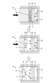
- FIG. 1 is a cross-sectional view schematically showing a configuration example of a filtering device according to Embodiment 1.
- FIG. FIG. 2 is a cross-sectional view showing the filtration (during compression) of the filtering device according to Embodiment 1.
- FIG. 3 is an explanatory diagram for explaining the operation of the filtering device according to Embodiment 1.
- FIG. 4 is a cross-sectional view schematically showing the configuration of the first electrode, filter medium, and second electrode.
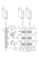
- 5 is an electrical equivalent circuit diagram showing the filtering device according to Embodiment 1.
- FIG. FIG. 6 is a flowchart showing how the filtering device according to Embodiment 1 is used.
- FIG. 7 is a cross-sectional view schematically showing a configuration example of a filtering device according to Embodiment 2.
- FIG. 8 is an explanatory diagram for explaining the operation of the filtering device according to Embodiment 2.
- FIG. 9 is an electrical equivalent circuit diagram showing a filtering device according to Embodiment 2.
- FIG. 1 is a cross-sectional view schematically showing a configuration example of a filtering device according to Embodiment 1.
- FIG. The filtration device 10 according to the first embodiment is a device that separates particles 71 from a slurry (undiluted solution) 70 (target treatment liquid) in which particles (particles to be separated) 71 are dispersed in a polar solvent 72 .
- the filter device 10 can be applied to the fields of life science, sewage treatment, wastewater treatment, and the like.
- life science the bio industry that cultures microorganisms such as cultured cells, microalgae, bacteria, bacteria, viruses, etc., and the use and application of enzymes, proteins, polysaccharides, lipids, etc.
- the filtration device 10 is a colloidal fine particle-based slurry in which surface-charged fine particles are highly dispersed by electrical repulsion, and can be applied to concentration and recovery of colloidal fine particles.
- the filtering device 10 includes an upper housing 11, a lid portion 12, a side housing 13, a lower housing 14, a conductor 15, and a cylinder (not shown). and have The filtration device 10 includes a first filter chamber 30, a first electrode 31, a second electrode 32, and a third electrode in an internal space surrounded by an upper housing 11, a side housing 13, and a lower housing 14. 33 and a filter medium 34 (see FIG. 3).
- a first power source 51 and a second power source 52 are electrically connected to the filtering device 10 .
- the direction in which the first electrode 31, the second electrode 32, the third electrode 33, and the filter medium 34 are arranged is the vertical direction.
- the upper housing 11 is a cylindrical member made of an insulating material.
- the side housing 13 is an annular member made of an insulating material and having a through hole 13a. A lower end portion of the upper housing 11 is inserted into the through hole 13 a of the side housing 13 . Also, the lower end of the upper housing 11 is slidably fitted to the inner peripheral surface of the through hole 13a. Therefore, the upper housing 11 is vertically slidable with respect to the side housings 13 .
- the lid portion 12 is arranged above the upper housing 11 and integrated with the upper housing 11 .
- a connecting portion 60 that connects with a shaft portion of a cylinder (not shown) is connected to the upper portion of the lid portion 12 .
- cylinders include air cylinders and hydraulic cylinders. Therefore, when the cylinder is driven, the lid portion 12 and the side housing 13 move up and down via the connecting portion 60 . Thereby, the volume of the first filter chamber 30 changes.
- the lower housing 14 is made of an insulating material and supports the side housing 13 .
- the lid portion 12 is provided to cover the upper surface of the upper housing 11 . Note that although the embodiment includes the cylinder and the connecting portion 60 , the present disclosure does not necessarily include the cylinder and the connecting portion 60 . In such a case, it is necessary for the operator to move the upper housing 11 vertically.
- the outer edges of the first electrode 31, the second electrode 32, and the filter material 34 are sandwiched between the side housing 13 and the lower housing 14 and fixed.
- the third electrode 33 is arranged inside the through hole of the side housing 13 . Further, the third electrode 33 is fixed to the lower surface of the upper housing 11 (the surface facing the lower housing 14) with fasteners such as bolts. Therefore, when the upper housing 11 moves up and down by driving the cylinder, the third electrode 33 also moves up and down.
- the facing direction in which the first electrode 31 and the third electrode 33 face each other is the vertical direction.
- the conductor 15 is an annular member provided so as to surround the side housing 13 and is provided between the side housing 13 and the lower housing 14 . A lower end side of the conductor 15 is connected to the outer edge of the first electrode 31 .
- the upper housing 11 and the conductor 15 are annular members, they are not limited to this, and may be polygonal or other shapes.
- the upper housing 11 and the side housing 13 are connected so as to be freely slidable (movable) in the vertical direction by a guide portion 21a. As a result, the upper housing 11 is supported by the side housings 13 without rattling in the planar direction perpendicular to the guide portion 21a.
- the side housing 13, the lower housing 14, and the conductor 15 are fixed by bolts 21b and 21c. As a result, the positions of the housings are fixed, and the space surrounded by the first electrode 31, the second electrode 32, the filter medium 34, the inner wall of the side housing 13, and the third electrode 33 is filled with the first filter chamber. 30 are formed.
- a sealing member such as an O-ring is provided at each connecting portion between the housings and between the electrodes, so that the first filter chamber 30 is provided in a sealed manner. Further, the distance between the upper housing 11 and the lower housing 14 is adjusted by driving the cylinder. As a result, the filtering device 10 can appropriately set the volume of the first filter chamber 30 according to the type and amount of the slurry (raw liquid) 70 (hereinafter sometimes referred to as the target treatment liquid).
- the upper housing 11 is provided with a slurry supply passage 11a, an exhaust passage 11b, and a through hole 11c.
- One end side of the slurry supply passage 11 a opens to the side surface of the upper housing 11 and is connected to the slurry supply section 16 .
- the other end side of the slurry supply passage 11 a is opened to the lower surface of the upper housing 11 and connected to the through hole 33 a of the third electrode 33 .
- the slurry supply valve 17 has a rod-shaped member 17a provided inside the slurry supply passage 11a, and the rod-shaped member 17a moves up and down in the slurry supply passage 11a to switch the open/closed state of the through hole 33a. can be done.
- the slurry (undiluted solution) 70 flows through the slurry supply section 16, the slurry supply passage 11a, and the through-hole 33a of the third electrode 33. It is supplied to the first filter chamber 30 . Further, when the through hole 33a is closed by the slurry supply valve 17, the supply of the slurry (undiluted solution) 70 to the first filter chamber 30 is stopped.
- the air discharge valve 19 has a rod-shaped member 19a provided inside the exhaust passage 11b. , the open/closed state of the through hole 33b can be switched.
- the slurry supply valve 17 and the air discharge valve 19 are fixed to the lid portion 12 . Therefore, when the cylinder is driven, the slurry supply valve 17 and the air discharge valve 19 move up and down together with the lid portion 12 and the side housing 13 .
- the air discharge valve 19 opens the through hole 33b.
- the air in the first filter chamber 30 is exhausted to the outside through the through hole 33b, the exhaust passage 11b, and the air exhaust portion 18.
- An air discharge valve 18 a is connected to the air discharge portion 18 .
- the air discharge valve 18a is, for example, a float valve, and is provided so that the air discharge valve 18a is closed when a predetermined amount of air in the first filter chamber 30 is discharged. After the first filter chamber 30 is completely exhausted, the air discharge valve 19 closes the through hole 33b.
- the third electrode 33 is electrically connected to the reference potential GND via the connection conductor 56 .
- the reference potential GND is, for example, the ground potential. However, the reference potential GND is not limited to this, and may be a predetermined fixed potential different from the ground potential.
- the first electrode 31 is electrically connected to the second terminal 51b of the first power supply 51 via the conductor 15 and the connection conductor 54. Also, the first electrode 31 is electrically connected to the first terminal 52a of the second power supply 52 via the conductor 15 and the connection conductor 55a.
- the lower housing 14 is provided with a concave second filter chamber 35, through holes 14a and 14b, and a connection hole 14c.
- the second filter chamber 35 is provided at a position overlapping the first filter chamber 30 on the upper surface of the lower housing 14 .
- the through hole 14 a connects the second filter chamber 35 and the discharge portion 22 .
- Particles 71 are separated from the slurry (undiluted solution) 70 supplied to the first filter chamber 30 by driving each electrode, and the polar solvent 72 (filtrate 75) from which the particles 71 are separated is transferred to the first electrode 31 and the filter medium 34. (see FIG. 3) and the second electrode 32 to flow into the second filter chamber 35 .
- Filtrate 75 containing polar solvent 72 from which particles 71 have been separated is collected in an external storage tank from outlet 22 of second filter chamber 35 through through hole 14b.
- connection hole 14c One end side of the connection hole 14c opens to the upper surface of the lower housing 14, and the outer edge of the second electrode 32 is provided to cover the opening 14d of the connection hole 14c. Further, the other end side of the connection hole 14 c opens to the side surface of the lower housing 14 .
- a connection conductor 55b is inserted into the connection hole 14c, and the connection conductor 55b and the second electrode 32 are connected. Thereby, the second electrode 32 is electrically connected to the second terminal 52 b of the second power supply 52 .
- the configuration of the filtering device 10 shown in FIG. 1 is merely an example, and the first filter chamber sandwiched between the first electrode 31, the second electrode 32, the filter medium 34 (see FIG. 3), and the third electrode 33 Any configuration can be used as long as 30 can be formed.
- the first electrode 31, the second electrode 32, and the third electrode 33 are made of, for example, a titanium alloy or an alumite-treated aluminum alloy, but are not limited to these.
- FIG. 2 is a cross-sectional view showing the filtration (during compression) of the filtration device according to Embodiment 1.
- FIG. 2 The filtering process of the filtering device 10 described above will be briefly described. 2, the through holes 33a and 33b of the third electrode 33 are closed by inserting the rod-shaped members 17a and 19a.
- a cylinder (not shown) is driven to move the lid portion 12 and the side housing 13 downward (see arrow X). That is, the third electrode 33 presses downward the slurry 70 supplied to the first filter chamber 30 . Thereby, the slurry 70 is pressed (squeezed) against the first electrode 31 , the second electrode 32 and the filter medium 34 .
- the liquid contained in the slurry 70 passes through the filter medium 34 to move to the second filter chamber 35 and is discharged from the discharge portion 22 .
- particles having a particle size larger than the mesh openings 34b (see FIG. 3) of the filter medium 34 cannot pass through the filter medium 34 and are deposited on the filter medium 34 as a dehydrated cake 80.
- pressing the slurry 70 against the first electrode 31, the second electrode 32 and the filter medium 34 by the third electrode 33 may be simply referred to as "squeezing".
- the filter device 10 of Embodiment 1 uses the first power source 51 and the second power source 52 for the first electrode 31, the second electrode 32, and the third electrode 33. It is squeezed while supplying a predetermined potential from and. Details of the filtering device 10 will be described below with reference to FIGS. 3 to 5 .
- FIG. 3 is an explanatory diagram for explaining the operation of the filtering device according to Embodiment 1.
- FIG. 3 in order to make the explanation easier to understand, the arrangement relationship between the first electrode 31, the second electrode 32, the third electrode 33, the filter medium 34, and the first filter chamber 30 and the second filter chamber 35 is schematically shown. showing.
- the first electrode 31 and the second electrode 32 are mesh electrodes having openings, for example.
- the first electrode 31 has a plurality of thin conductive wires 31a, and a plurality of first openings 31b are provided between the thin conductive wires 31a.
- the second electrode 32 has a plurality of thin conductive wires 32a, and a plurality of second openings 32b are provided between the thin conductive wires 32a.
- the second electrode 32 is provided to face one surface (lower surface) of the first electrode 31 with the filter medium 34 interposed therebetween.
- the filter material 34 is provided between the first electrode 31 and the second electrode 32 .
- the first electrode 31 and the second electrode 32 are provided in direct contact with the filter medium 34 .
- the plurality of thin conductive wires 31a and the plurality of thin conductive wires 32a may be metal or carbon fiber.
- the first electrode 31 and the second electrode 32 are not limited to being in direct contact with the filter medium 34, and may be arranged with a gap between them.
- the filter medium 34 is formed by providing a plurality of openings 34b in a filtration membrane 34a.
- a microfiltration membrane Microfiltration Membrane
- UF membrane Ultrafiltration Membrane
- the filter medium 34 is made of an insulating material such as a resin material.
- the first opening 31b of the first electrode 31, the second opening 32b of the second electrode 32, and the opening 34b of the filter medium 34 are shown to have the same size. The sizes of the first opening 31b, the second opening 32b and the opening 34b may be different.
- FIG. 4 is a cross-sectional view schematically showing the configuration of the first electrode, filter medium and second electrode.
- the diameter D3 of the opening 34b provided in the filter medium 34 is smaller than the diameter D1 of the first opening 31b of the first electrode 31 and the diameter of the second opening 32b of the second electrode 32. smaller than D2.
- the arrangement pitch of the plurality of conductive fine wires 31a, the arrangement pitch of the plurality of conductive fine wires 32a, and the arrangement pitch of the filtration membranes 34a are provided mutually different.
- the diameter D1 of the first opening 31b of the first electrode 31 is 0.5 ⁇ m or more and 500 ⁇ m or less, for example, about 70 ⁇ m.
- a diameter D2 of the second opening 32b of the second electrode 32 is 0.5 ⁇ m or more and 1000 ⁇ m or less, for example, about 100 ⁇ m.
- a diameter D3 of the plurality of openings 34b provided in the filter medium 34 is approximately 0.1 ⁇ m to 100 ⁇ m, more preferably approximately 1 ⁇ m to 7 ⁇ m.
- the diameter D1 of the first opening 31b of the first electrode 31 is smaller than the diameter D2 of the second opening 32b of the second electrode 32.
- the diameter D1 of the first opening 31b of the first electrode 31 may be formed to have the same size as the diameter D2 of the second opening 32b of the second electrode 32 .
- the openings 34b of the filter material 34 are provided so as not to overlap the plurality of thin conductive wires 31a and the plurality of thin conductive wires 32a at least in the regions overlapping the first openings 31b and the second openings 32b.
- the distance between the first electrode 31 and the second electrode 32 is defined by the thickness of the filter medium 34 .
- the third electrode 33 is a plate-like member and provided to face the other surface (upper surface) of the first electrode 31 with the first filter chamber 30 interposed therebetween. 3, the through holes 33a and 33b and the recess 33c (see FIG. 1) of the third electrode 33 are omitted.
- the first filter chamber 30 is provided in contact with the other surface (upper surface) of the first electrode 31 .
- the first filter chamber 30 is supplied with the slurry (undiluted solution) 70 containing the particles 71 to be separated and the polar solvent 72 .
- the particles 71 are, for example, biomass fine particles or colloidal fine particles, and the surfaces of the particles are negatively charged.
- the particles 71 are chlorella, microalgae spirulina, colloidal silica, Escherichia coli, activated sewage sludge, or the like.
- the diameter of the particles 71 varies depending on the technical field to which it is applied and the type of separation object, but is approximately 5 nm or more and 2000 ⁇ m or less, for example, approximately 20 nm or more and 500 ⁇ m or less.
- the polar solvent 72 in which the particles 71 are dispersed is water, and the water molecules 73 are positively charged. As a result, the slurry (undiluted solution) 70 as a whole is in an electrically balanced state.
- the polar solvent 72 is not limited to water, and may be, for example, alcohol. That is, the polar solvent 72 should just be a polar solvent.
- the first power supply 51 supplies the first electrode 31 with the first potential V1 having the same polarity as the particles 71 .
- the first potential V1 is -60V, for example.
- the second power supply 52 supplies the second electrode 32 with a second potential V2 having the same polarity as that of the particles 71 and a larger absolute value than the first potential V1.
- the second potential V2 is -70V, for example.
- the third electrode 33 is connected to the reference potential GND.
- the reference potential GND is the ground potential as described above, ideally 0V. Note that the reference potential GND supplied to the third electrode 33 is not limited to 0V, and may be a predetermined fixed potential.
- the absolute values of the first potential V1 and the second potential V2 can be set within a range of 1 mV or more and 1000 V or less.
- FIG. 5 is an electrical equivalent circuit diagram showing the filtering device according to Embodiment 1.
- the first power source 51 is a constant voltage source and the second power source 52 is a constant current source.
- a resistance component R1 and a capacitance component C are connected in parallel between the first electrode 31 and the second electrode 32 .
- the resistance component R1 and the capacitance component C are equivalently represented by the filter medium 34 provided with a large number of openings 34b.
- a resistance component R2 is connected between the first electrode 31 and the third electrode 33 .
- the resistance component R2 is equivalently represented by the slurry (undiluted solution) 70 in the first filter chamber 30 .
- the second power supply 52 may be a constant voltage power supply or a constant current power supply.
- the second power supply 52 is a constant current source, so depending on the filtering state of the filter device 10, that is, the resistance component R1 of the filter medium 34 and the resistance component R2 of the first filter chamber 30 change , the second potential V2 changes.
- the second potential V2 has the same polarity as the particle 71 and maintains a value greater than the absolute value of the first potential V1.
- each electrode (31, 32, 33) during filtration (during compression) of the filtering device 10 will be described.
- a repulsive force F1 is generated between the negatively charged particles 71 and the first electrode 31 when the filtering device 10 is squeezed. That is, the negatively charged particles 71 move away from the first electrode 31 and approach the third electrode 33 due to the repulsive force F ⁇ b>1 generated between them and the first electrode 31 .
- the filter device 10 when the filter device 10 is squeezed, the slurry 70 itself is pressed against the first electrode 31 and the filter medium 34, but the particles 71 are distributed toward the third electrode 33 inside the slurry 70. Therefore, clogging of the openings 34b of the filter medium 34 with the particles 71 is suppressed. Also, as the water contained in the slurry 70 decreases due to the compression, the distance between the first electrode 31 and the particles 71 becomes smaller. Then, toward the end of squeezing, the particles 71 come into contact with the filter medium 34 . Ultimately, particles 71 contained in slurry 70 are layered on first electrode 31 and filter media 34 to form dewatered cake 80 .
- an attractive force is generated between the positively charged water molecules 73 and the first electrode 31 .
- the attractive force F ⁇ b>2 acting on the positively charged water molecules 73 acts in the direction indicated by the arrow, that is, in the direction from the third electrode 33 toward the first electrode 31 .
- the positively charged water molecules 73 move to the first electrode 31 side.
- the electric field E of the barrier from the first electrode 31 to the second electrode 32 (in FIG. , dashed line) are formed.
- the water molecules 73 that have moved to the first electrode 31 side receive force from the electric field E, are pulled toward the second electrode 32 side, and pass through the filter medium 34 .
- the surrounding water molecules 73 are also dragged toward the second electrode 32, generating an electroosmotic flow.
- the polar solvent 72 (filtrate 75 ) containing positively charged water molecules 73 flows into the second filter chamber 35 . Therefore, the amount of water discharged per unit time (the amount of water transferred to the second filter chamber 35) increases as compared to the case of simple filtration.
- the filtering device 10 of Embodiment 1 since the particles 71 do not come into contact with the filter medium 34 from the start of filtration to the end of the compression, the filtration resistance of the filter medium 34 does not increase. That is, the high filtration speed state (non-clogging state) of the filter medium 34 is maintained for a long time, and the time required for the filtration process is shortened. In addition, since the amount of water discharged per unit time (the amount of water transferred to the second filter chamber 35) is increased, the time required for the filtration process (compressing process) is further shortened. Also, the particles 71 receive a repulsive force from the first electrode 31 and are distributed toward the third electrode 33 . Therefore, filtration leakage (particles 71 passing through the openings 34b of the filter medium 34) is avoided.
- the electric field formed between the first electrode 31 and the second electrode 32 is controlled to control the particle level (particle diameter) passing through the filter medium 34. good too.
- a barrier is formed between the first electrode 31 and the second electrode 32. is formed (see FIG. 3), and particles 71 having a particle size smaller than the mesh opening 34b of the filter medium 34 can be suppressed from passing through the filter medium 34.
- FIG. That is, according to this embodiment, it is also possible to compress the nanoparticles.
- the particle size to be separated can be changed to the equivalent of an outer filtration membrane (UF membrane) or a nanofiltration membrane (NF membrane).
- An ultrafiltration membrane (UF membrane) is a filtration membrane with an opening diameter of approximately 10 nm or more and 100 nm or less.
- a nanofiltration membrane (NF membrane) is a filtration membrane having an opening diameter of about 1 nm or more and 10 nm or less.
- FIG. 6 is a flowchart showing how the filtering device according to Embodiment 1 is used.
- the slurry supply step S1 is performed first.
- the slurry supply step S ⁇ b>1 is a step of supplying the slurry 70 to the first filter chamber 30 of the filtration device 10 .
- the vertical position of the third electrode 33 is adjusted so that the third electrode 33 and the liquid surface of the slurry 70 are brought into contact with each other.
- a predetermined voltage is applied to the first electrode 31 , the second electrode 32 and the third electrode 33 .
- many particles 71 are distributed near the third electrode 33 and many water molecules 73 are distributed near the first electrode 31 in the first filter chamber 30 .
- the filtering process step S2 is performed.
- the filtration treatment step S2 is a step of continuously moving the third electrode 33 downward to apply filtration pressure to the slurry 70 .
- many water molecules 73 in the slurry 70 near the first electrode 31 pass through the filter medium 34 and move to the second filter chamber 35 .
- the filter medium 34 is not clogged. Therefore, the water molecules 73 smoothly pass through the filter medium 34 .
- the contact state between the third electrode 33 and the slurry 70 is maintained because the third electrode 33 is continuously moved downward. In other words, the state in which the particles 71 are distributed near the third electrode 33 and the water molecules 73 are distributed near the first electrode 31 is maintained. Therefore, a smooth filtration process is continuously performed, and the time for the filtration process is shortened.
- the pressing step S3 is a step of continuously moving the position of the third electrode 33 downward, like the filtering step S2.
- the slurry 70 is pressed (squeezed) against the first electrode 31 , the second electrode 32 and the filter medium 34 .
- Most of the water molecules 73 contained in the slurry 70 move to the second filter chamber 35 .
- the slurry 70 deposited on the filter media 34 becomes the dehydrated cake 80 .
- the time required for the pressing process is shortened.
- the downward movement of the third electrode 33 is stopped.
- voltage supply to the first electrode 31, the second electrode 32, and the third electrode 33 is stopped.
- the processing by the filtering device 10 ends.
- the configuration of the filtering device 10 described above is merely an example, and can be changed as appropriate.
- the negative filter plate formed by laminating the first electrode 31, the filter medium 34, and the second electrode 32 and the third electrode 33 are arranged to face each other in a parallel plate shape.
- the negative filter plate formed by stacking the first electrode 31, the filter medium 34 and the second electrode 32, and the third electrode 33 may each have a curved surface.
- the shape and arrangement of the negative filter plate and the third electrode 33 can be appropriately changed according to the shape and structure of the filtering device 10 .
- the concentration of the slurry (undiluted solution) 70 which is the target treatment liquid supplied to the first filter chamber 30, is not particularly limited, and can be changed according to the field to which the filtration device 10 is applied.
- first potential V1 and the second potential V2 are changed as appropriate according to the type of the particles 71 to be separated and the required filtration characteristics.
- the filtering device 10 of Embodiment 1 is provided with the first electrode 31 provided with the plurality of first openings 31b and the plurality of second openings 32b.
- a second electrode 32 provided opposite to and a plurality of openings 34b are provided, a filter medium 34 provided between the first electrode 31 and the second electrode 32, and the other surface of the first electrode 31
- a filter chamber (first filter chamber 30) provided in contact with and supplied with a slurry (raw solution) 70 (target treatment liquid) containing particles 71 to be separated and a polar solvent 72, and a first electrode sandwiching the filter medium 34 31 and the second electrode 32 or the third electrode 33 are movable in the facing direction (vertical direction) in which the first electrode 31 and the third electrode 33 face each other.
- the first potential V1 having the same polarity as the particles (particles 71) is supplied to the first electrode 31.
- FIG. The second electrode 32 is supplied with a second potential V2 having the same polarity as the particles (particles 71).
- a reference potential GND is supplied to the third electrode 33 .
- the absolute value of the second potential V2 is greater than the absolute value of the first potential V1.
- the first electrode 31 and the second electrode 32 or the third electrode 33 are moved to squeeze the slurry 70 deposited on the filter medium. Further, by supplying a predetermined potential to the first electrode 31, the second electrode 32, and the third electrode 33, a repulsive force generated between the first electrode 31 and the particles 71 acts. As a result, the particles 71 move away from the first electrode 31 due to the electrophoretic flow. As a result, an increase in the filtration resistance of the surface of the first electrode 31 and the filter medium 34 is suppressed, and the filtration processing time is shortened. In addition, the amount of water discharged per unit time (movement to the second filter chamber 35 amount) increases. This further shortens the filtering process time.
- the particles 71 are separated from the first electrode 31 by the repulsive force generated between the first electrode 31 and the particles 71, and filtration leakage is less likely to occur. Therefore, a polymer flocculant becomes unnecessary. Since the third electrode 33 is connected to the reference potential GND, the size of the filtering device 10 can be reduced compared to the case where the first electrode 31, the second electrode 32, and the third electrode 33 are each provided with a power source.
- the filtering device 10 also includes a cylinder (not shown) that moves the upper housing 11 vertically (opposing direction).
- the upper housing 11 is moved up and down by a cylinder (not shown).
- the second electrode 32 and the filter medium 34) may be vertically moved to compress.
- FIG. 7 is a cross-sectional view schematically showing a configuration example of a filtering device according to Embodiment 2.
- FIG. 8 is an explanatory diagram for explaining the operation of the filtering device according to Embodiment 2.
- FIG. The same reference numerals are given to the same components as those described in the above-described embodiment, and overlapping descriptions are omitted.
- the filtering device 10 includes an upper housing 11, a lid portion 12, a side housing 13, a lower housing 14, a conductor 15, and a cylinder (not shown). and have The filtration device 10 further includes a first filter chamber 30, a first electrode 31, a second electrode 32, and a second It has three electrodes 33 and a filter medium 34 (see FIG. 8).
- a first power source 51 , a second power source 52 and a third power source 53 are electrically connected to the filtering device 10 .
- connection conductor 56 is inserted into the through hole 11c, and the connection conductor 56 and the third electrode 33 are connected at the recess 33c. Thereby, the third electrode 33 is electrically connected to the first terminal 53 a of the third power supply 53 via the connection conductor 56 .
- the first electrode 31 is electrically connected to the second terminal 51b of the first power supply 51 via the conductor 15 and the connection conductor 54. Also, the first electrode 31 is electrically connected to the first terminal 52a of the second power supply 52 via the conductor 15 and the connection conductor 55a.
- the second terminal 53b of the third power supply 53 and the first terminal 51a of the first power supply 51 are connected to the reference potential GND.
- the reference potential GND is, for example, the ground potential. However, the reference potential GND is not limited to this, and may be a predetermined fixed potential.
- FIG. 9 is an electrical equivalent circuit diagram showing a filtering device according to Embodiment 2.
- the first power source 51 and the third power source 53 are constant voltage sources, and the second power source 52 is a constant current source.
- a resistance component R1 and a capacitance component C are connected in parallel between the first electrode 31 and the second electrode 32 .
- the resistance component R1 and the capacitance component C are equivalently represented by the filter medium 34 provided with a large number of openings 34b.
- a resistance component R2 is connected between the first electrode 31 and the third electrode 33 .
- the resistance component R2 is equivalently represented by the slurry (undiluted solution) 70 in the first filter chamber 30 .
- the second power supply 52 may be a constant voltage power supply or a constant current power supply.
- the second power supply 52 is a constant current source, so it changes according to the filtering state of the filter device 10, that is, changes in the resistance component R1 of the filter medium 34 and the resistance component R2 of the first filter chamber 30. Accordingly, the second potential V12 changes.
- the second potential V12 has the same polarity as the particle 71 and maintains a value greater than the absolute value of the first potential V11.
- each electrode (31, 32, 33) when the filtering device 10 is squeezed will be described with reference to FIG.
- a repulsive force is generated between the negatively charged particles 71 and the first electrode 31 .
- an attractive force is generated between the negatively charged particles 71 and the third electrode 33 . Therefore, a resultant force F3 obtained by synthesizing the repulsive force and the attractive force generated in the negatively charged particles 71 acts in a direction away from the first electrode 31 and toward the third electrode 33 .
- the negatively charged particles 71 move toward the third electrode 33 by electrophoresis.
- the particles 71 are distributed toward the third electrode 33 , and clogging of the openings 34 b of the filter medium 34 with the particles 71 is suppressed. Therefore, the filtration resistance of the filter medium 34 does not increase until about the end of the compression.
- the positively charged water molecules 73 generate an attractive force F2 between them and the first electrode 31 .
- the attractive force F ⁇ b>2 acting on the positively charged water molecules 73 acts in the direction indicated by the arrow, that is, in the direction from the third electrode 33 toward the first electrode 31 .
- the positively charged water molecules 73 move to the first electrode 31 side.
- an electric field is formed from the first electrode 31 to the second electrode 32 so as to penetrate the filter medium 34 in the thickness direction.
- the water molecules 73 that have moved to the first electrode 31 side receive force from the electric field, are pulled toward the second electrode 32 side, and pass through the filter medium 34 .
- As the positively charged water molecules 73 move uncharged water molecules are also dragged toward the second electrode 32, forming an electroosmotic flow.
- the polar solvent 72 (filtrate 75 ) containing positively charged water molecules 73 flows into the second filter chamber 35 . Therefore, the amount of water discharged per unit time (the amount of water transferred to the second filter chamber 35) is increased compared to the case of simply squeezing, and the filtration time is further shortened.
- the filter device 10 of Embodiment 2 the high filtration rate of the filter medium 34 (non-clogging state) is maintained for a long time, and the time required for the filtration process is shortened.
- the amount of water discharged per unit time (the amount of water transferred to the second filter chamber 35) is increased, the filtration processing time is further shortened.
- the particles 71 receive a repulsive force from the first electrode 31, and filtering leakage is avoided. Therefore, a polymer flocculant for flocculating the particles 71 is not required.
- the particle level (particle diameter) passing through the filter medium 34 can also be controlled.
- a barrier is formed between the first electrode 31 and the second electrode 32. is formed, and particles 71 having a particle size (5 nm or more and 2000 ⁇ m or less) smaller than the mesh size (0.1 ⁇ m or more and 100 ⁇ m or less) 34 b of the filter medium 34 can be suppressed from passing through the filter medium 34 .
- an ultrafiltration membrane (UF membrane) is a filtration membrane with an opening diameter of approximately 10 nm or more and 100 nm or less.
- a nanofiltration membrane (NF membrane) is a filtration membrane having an opening diameter of about 1 nm or more and 10 nm or less.
- the configuration of the filtering device 10 described above is merely an example, and can be changed as appropriate.
- the negative filter plate formed by laminating the first electrode 31, the filter medium 34, and the second electrode 32 and the third electrode 33 are arranged to face each other in a parallel plate shape.
- the negative filter plate formed by stacking the first electrode 31, the filter medium 34 and the second electrode 32, and the third electrode 33 may each have a curved surface.
- the shape and arrangement of the negative filter plate and the third electrode 33 can be appropriately changed according to the shape and structure of the filtering device 10 .
- the concentration of the slurry (undiluted solution) 70 which is the target treatment liquid supplied to the first filter chamber 30, is not particularly limited, and can be changed according to the field to which the filtration device 10 is applied.
- first potential V11, the second potential V12, and the third potential V13 are preferably changed as appropriate according to the type of the particles 71 to be separated and the required filtration characteristics.
- the first potential V11 having the same polarity as the particles (particles 71) is supplied to the first electrode 31.
- a second potential V ⁇ b>12 having the same polarity as the particles (particles 71 ) is supplied to the second electrode 32 .
- a third potential V ⁇ b>13 having a polarity different from that of the particles (particles 71 ) is supplied to the third electrode 33 .
- the absolute value of the second potential V12 is greater than the absolute value of the first potential V11.
- the first electrode 31 and the second electrode 32 or the third electrode 33 are moved to squeeze the slurry 70 deposited on the filter medium. Further, by supplying a predetermined potential to the first electrode 31, the second electrode 32, and the third electrode 33, a repulsive force acts between the first electrode 31 and the particles 71, and the third electrode 33 and the particles 71 There is a force of attraction between As a result, the particles 71 move away from the first electrode 31 due to the electrophoretic flow. As a result, an increase in the filtration resistance of the surface of the first electrode 31 and the filter medium 34 is suppressed, and the filtration processing time is shortened.
- the amount of water discharged per unit time increases. Therefore, the time required for the filtering process is further shortened.
- the particles 71 are separated from the first electrode 31 by the repulsive force generated between the first electrode 31 and the particles 71, filtration leakage is less likely to occur, and a polymer flocculant is not required.
- the particles 71 located near the first electrode 31 generate a stronger repulsive force than in the filtering device 10 of the first embodiment.
- a stronger attractive force is generated on the particles 71 positioned closer to the third electrode 33 than in the filtering device 10 of the first embodiment.
- a resultant force F3 of the repulsive force (see F1 in FIG. 3) and the attractive force (f2) generated on the negatively charged particles 71 is compared with the repulsive force F1 generated on the particles 71 in the filtering device 10 of the first embodiment.
- F1 ⁇ F3 and the resultant force F3 of the repulsive force and the attractive force generated in the negatively charged particles 71 and the force to move toward the third electrode 33 due to electrophoresis are large.
- the filtering device 10 of Embodiment 2 includes the third electrode 33, and by applying a predetermined potential to the third electrode 33, the first electrode 31 and Due to the resultant force F3 of the repulsive force and the attractive force acting therebetween, the effect of separating from the first electrode 31 in the range of several nanometers to several micrometers is increased. As a result, the time when the filtration resistance of the filter medium 34 increases is delayed. Therefore, the state in which the filtration resistance of the filter medium 34 is small continues for a long period of time, and the filtration rate is further improved.
Abstract
ろ過装置10は、複数の第1開口31bが設けられた第1電極31と、複数の第2開口32bが設けられ、第1電極31の一方の面と対向して設けられた第2電極32と、複数の目開きが設けられ、第1電極31と第2電極32との間に設けられたろ材34と、第1電極31の他方の面と接して設けられ、分離対象の粒子と液体とを含む対象処理液が供給されるろ室と、ろ室を挟んで第1電極31と対向する第3電極33とを含む。ろ材34を挟む第1電極31と第2電極32、又は第3電極33は、第1電極31と第3電極33とが対向する対向方向に移動可能となっている。
Description
本開示は、ろ過装置に関する。
スラリーをろ過するろ過装置として、従来から圧搾方式のろ過装置が利用されている。下記特許文献に示すように、従来の圧搾方式のろ過装置は、容器の底部に、ろ布などのろ材が設置される。ろ材の上には、スラリーが堆積される。スラリーの上方には、押圧板が配置される。押圧板が下降すると、スラリーがろ材に押し付けられる。スラリーに含まれる液体は、ろ材を通過し、容器の外部に排出される。一方、固体はろ材を通過せず、ろ材の上に脱水ケークが生成される。
従来の圧搾方式のろ過装置は、スラリーに含まれる粒子がろ材を塞いでしまい、ろ材の目詰まりが発生する。よって、ろ過速度の低下が発生し、ろ過処理の時間が長時間となっている。
上記課題に鑑み、本開示は、ろ過処理の時間が短縮するろ過装置を提供することを目的とする。
本開示の第1側面のろ過装置は、複数の第1開口が設けられた第1電極と、複数の第2開口が設けられ、前記第1電極の一方の面と対向して設けられた第2電極と、複数の目開きが設けられ、前記第1電極と前記第2電極との間に設けられたろ材と、前記第1電極の他方の面と接して設けられ、分離対象の粒子と液体とを含む対象処理液が供給されるろ室と、前記ろ室を挟んで前記第1電極と対向する第3電極と、を含む。前記ろ材を挟む前記第1電極と第2電極、又は前記第3電極は、前記第1電極と前記第3電極とが対向する対向方向に移動可能となっている。
本開示のろ過装置によれば、ろ過処理の時間が短縮する。
以下、本開示につき図面を参照しつつ詳細に説明する。なお、下記の発明を実施するための形態(以下、実施形態という)により本開示が限定されるものではない。また、下記実施形態における構成要素には、当業者が容易に想定できるもの、実質的に同一のもの、いわゆる均等の範囲のものが含まれる。さらに、下記実施形態で開示した構成要素は適宜組み合わせることが可能である。
(実施形態1)
図1は、実施形態1に係るろ過装置の構成例を模式的に示す断面図である。実施形態1に係るろ過装置10は、極性溶媒72中に粒子(分離対象の粒子)71が分散されたスラリー(原液)70(対象処理液)から、粒子71を分離する装置である。具体的に、ろ過装置10は、ライフサイエンス分野、下水処理、及び排水処理分野等に適用できる。ライフサイエンス分野では、培養細胞、微細藻類、細菌、バクテリア、ウイルス等の微生物体培養を行うバイオ産業や、培養微生物体が体外、体内に生産する酵素、タンパク質、多糖類、脂質等の利用、応用分野であるバイオ創薬や化粧品業界、又は、醸造、発酵、搾汁、飲料等を扱うビバレッジ産業に適用できる。下水処理、排水処理分野では、難ろ過性の微細バイオマス水系スラリーで、バイオマス微粒子の分離に適用できる。あるいは、ろ過装置10は、表面帯電した微粒子が電気的反発作用で高分散したコロイド微粒子系スラリーで、コロイド微粒子の濃縮回収用途に適用できる。
図1は、実施形態1に係るろ過装置の構成例を模式的に示す断面図である。実施形態1に係るろ過装置10は、極性溶媒72中に粒子(分離対象の粒子)71が分散されたスラリー(原液)70(対象処理液)から、粒子71を分離する装置である。具体的に、ろ過装置10は、ライフサイエンス分野、下水処理、及び排水処理分野等に適用できる。ライフサイエンス分野では、培養細胞、微細藻類、細菌、バクテリア、ウイルス等の微生物体培養を行うバイオ産業や、培養微生物体が体外、体内に生産する酵素、タンパク質、多糖類、脂質等の利用、応用分野であるバイオ創薬や化粧品業界、又は、醸造、発酵、搾汁、飲料等を扱うビバレッジ産業に適用できる。下水処理、排水処理分野では、難ろ過性の微細バイオマス水系スラリーで、バイオマス微粒子の分離に適用できる。あるいは、ろ過装置10は、表面帯電した微粒子が電気的反発作用で高分散したコロイド微粒子系スラリーで、コロイド微粒子の濃縮回収用途に適用できる。
図1に示すように、実施形態1に係るろ過装置10は、上部筐体11と、蓋部12と、側部筐体13と、下部筐体14と、導体15と、シリンダ(不図示)と、を有する。ろ過装置10は、上部筐体11、側部筐体13及び下部筐体14で囲まれた内部空間に、第1ろ室30と、第1電極31と、第2電極32と、第3電極33と、ろ材34(図3参照)と、を有する。ろ過装置10には、第1電源51と第2電源52が電気的に接続されている。なお、第1電極31と第2電極32と第3電極33とろ材34とが配置される方向が上下方向である。
上部筐体11は、絶縁材料で形成された円柱状の部材である。側部筐体13は、絶縁材料で形成され、貫通孔13aを有する環状の部材である。上部筐体11の下端部が側部筐体13の貫通孔13aに挿入される。また、上部筐体11の下端部は、貫通孔13aの内周面に摺動自在に嵌合している。よって、側部筐体13に対し、上部筐体11は、上下方向にスライド自在となっている。蓋部12は、上部筐体11の上方に配置され、上部筐体11と一体化している。
蓋部12の上方には、シリンダ(不図示)のシャフト部と連結する連結部60が連結している。シリンダは、エアシリンダや油圧シリンダなどが挙げられる。よって、シリンダが駆動すると、連結部60を介して蓋部12及び側部筐体13が上下動する。これにより、第1ろ室30の容積が変化する。下部筐体14は、絶縁材料で形成され、側部筐体13を支持する。蓋部12は、上部筐体11の上面を覆って設けられる。なお、実施形態では、シリンダ及び連結部60を備えているが、本開示は、シリンダ及び連結部60を備えていなくてもよい。このような場合、作業者が上部筐体11を上下方向に移動させるように作業する必要がある。
第1電極31、第2電極32、及びろ材34(図3参照)の外縁は、側部筐体13と下部筐体14との間に挟まれて固定される。第3電極33は、側部筐体13の貫通孔の内部に配置されている。また、第3電極33は、上部筐体11の下面(下部筐体14と対向する面)に、ボルト等の締結具により固定されている。よって、シリンダの駆動により上部筐体11が上下動すると、第3電極33も上下動する。なお、第1電極31と第3電極33が対向する対向方向は、上下方向である。導体15は、側部筐体13の周囲を囲むように設けられた環状の部材であり、側部筐体13と下部筐体14との間に設けられる。導体15の下端側は、第1電極31の外縁と接続される。なお、上部筐体11及び導体15は、環状の部材としているが、これに限定されるものではなく、多角形状等他の形状としてもよい。
上部筐体11と側部筐体13とは、ガイド部21aにより上下方向にスライド自在(移動自在)に連結している。これにより、ガイド部21aを垂線とする平面方向にガタツキなく、上部筐体11が側部筐体13に支持される。側部筐体13と下部筐体14と導体15とは、ボルト21b、21cにより固定される。これにより、各筐体の位置が固定され、第1電極31、第2電極32及びろ材34と、側部筐体13の内壁と、第3電極33とで囲まれた空間に第1ろ室30が形成される。また、各筐体間及び各電極間の接続部分には、それぞれOリング等の封止部材が設けられ、第1ろ室30が密閉して設けられる。また、シリンダの駆動により、上部筐体11は、下部筐体14との距離が調整される。これにより、ろ過装置10は、スラリー(原液)70(以下、対象処理液ということもある)の種類や量に応じて、第1ろ室30の容積を適切に設定できる。
上部筐体11には、スラリー供給通路11aと、排気通路11bと、貫通孔11cとが設けられる。スラリー供給通路11aの一端側は、上部筐体11の側面に開口し、スラリー供給部16に接続される。スラリー供給通路11aの他端側は、上部筐体11の下面に開口し、第3電極33の貫通孔33aと繋がって設けられる。スラリー供給バルブ17は、スラリー供給通路11aの内部に設けられた棒状部材17aを有し、棒状部材17aがスラリー供給通路11a内を上下方向に移動することで、貫通孔33aの開閉状態を切り替えることができる。
これにより、例えば、スラリー供給バルブ17の動作により貫通孔33aが開放状態の場合に、スラリー(原液)70は、スラリー供給部16、スラリー供給通路11a、第3電極33の貫通孔33aを介して第1ろ室30に供給される。また、スラリー供給バルブ17により貫通孔33aが閉じられた状態の場合、スラリー(原液)70の第1ろ室30への供給が停止する。
排気通路11bの一端側は、上部筐体11の側面に開口し、エア排出部18に接続される。排気通路11bの他端側は、上部筐体11の下面に開口し、第3電極33の貫通孔33bと繋がって設けられる。エア排出用のバルブ19は、排気通路11bの内部に設けられた棒状部材19aを有し、棒状部材19aが排気通路11b内を上下方向に移動し、貫通孔33bにその先端が挿抜されることで、貫通孔33bの開閉状態を切り替えることができる。
なお、スラリー供給バルブ17及びエア排出用のバルブ19は、蓋部12に固定されている。よって、シリンダが駆動すると、スラリー供給バルブ17及びエア排出用のバルブ19は、蓋部12及び側部筐体13とともに上下動する。
第1ろ室30にスラリー(原液)70が供給される際に、エア排出用のバルブ19は、貫通孔33bを開放状態にする。これにより、第1ろ室30内の空気は、貫通孔33b、排気通路11b及びエア排出部18を介して外部に排気される。エア排出部18にはエア排出弁18aが接続されている。エア排出弁18aは、例えばフロート弁であり、第1ろ室30内の所定量の空気が排気されるとエア排出弁18aが閉じられるように設けられている。第1ろ室30内の排気が完了した後、エア排出用のバルブ19は貫通孔33bを閉じる。
貫通孔11cの一端側は上部筐体11の上面に開口する。貫通孔11cの他端側は上部筐体11の下面に開口し、第3電極33の凹部33cと繋がって設けられる。貫通孔11cには、接続導体56が挿入され、凹部33cで接続導体56と第3電極33とが接続される。これにより、第3電極33は、接続導体56を介して基準電位GNDと電気的に接続される。基準電位GNDは、例えばグランド電位である。ただし、これに限定されず、基準電位GNDは、グランド電位とは異なる所定の固定された電位であってもよい。
第1電極31は、導体15及び接続導体54を介して第1電源51の第2端子51bと電気的に接続される。また、第1電極31は、導体15及び接続導体55aを介して第2電源52の第1端子52aと電気的に接続される。
下部筐体14には、凹状の第2ろ室35と、貫通孔14a、14bと、接続孔14cとが設けられている。第2ろ室35は、下部筐体14の上面で、第1ろ室30と重なる位置に設けられる。貫通孔14aは、第2ろ室35と排出部22とを繋ぐ。第1ろ室30に供給されたスラリー(原液)70は、各電極の駆動により粒子71が分離され、粒子71が分離された極性溶媒72(ろ液75)は、第1電極31、ろ材34(図3参照)及び第2電極32を通過して、第2ろ室35に流れる。粒子71が分離された極性溶媒72を含むろ液75は、第2ろ室35の排出部22から貫通孔14bを介して外部の貯留タンクに溜められる。
接続孔14cの一端側は、下部筐体14の上面に開口し、第2電極32の外縁は、接続孔14cの開口部14dを覆って設けられる。また、接続孔14cの他端側は、下部筐体14の側面に開口する。接続孔14cには接続導体55bが挿入され、接続導体55bと第2電極32とが接続される。これにより、第2電極32は、第2電源52の第2端子52bと電気的に接続される。
なお、図1に示すろ過装置10の構成は、あくまで一例であり、第1電極31、第2電極32及びろ材34(図3参照)と、第3電極33とで挟まれた第1ろ室30を形成できればどのような構成であってもよい。第1電極31、第2電極32及び第3電極33は、例えば、チタン合金やアルマイト処理されたアルミニウム合金等が用いられるが、これらに限定されるものではない。
図2は、実施形態1に係るろ過装置のろ過時(圧搾時)を示す断面図である。上記したろ過装置10のろ過処理を簡単に説明する。ろ過装置10のろ過処理時、図2に示すように、第3電極33の貫通孔33aと貫通孔33bは、棒状部材17aと棒状部材19aが挿入されて閉じている。シリンダ(不図示)が駆動し、蓋部12及び側部筐体13が下方に移動する(矢印Xを参照)。つまり、第3電極33は、第1ろ室30に供給されたスラリー70を下方に押圧する。これにより、スラリー70は、第1電極31、第2電極32及びろ材34に押し付けられる(圧搾される)。そして、スラリー70に含まれる液体は、ろ材34を通過して第2ろ室35に移動し、排出部22から排出される。一方、スラリー70に含まれる粒子のうち粒径がろ材34の目開き34b(図3参照)よりも大きい粒子は、ろ材34を通過できず、ろ材34上に脱水ケーク80として堆積する。以下、第3電極33でスラリー70を第1電極31、第2電極32及びろ材34に押し付けることを単に「圧搾」と称することがある。
また、実施形態1のろ過装置10は、ろ材34のろ過抵抗の増加を回避するため、第1電極31と第2電極32と第3電極33に対して、第1電源51と第2電源52とから所定の電位を供給しながら、圧搾している。以下、図3から図5を参照しながら、ろ過装置10の詳細を説明する。
図3は、実施形態1に係るろ過装置の動作を説明するための説明図である。図3では、説明を分かりやすくするために、第1電極31、第2電極32、第3電極33及びろ材34と、第1ろ室30及び第2ろ室35との配置関係を模式的に示している。
図3に示すように、第1電極31及び第2電極32は、例えば開口を有するメッシュ状の電極である。具体的には、第1電極31は、複数の導電細線31aを有し、複数の導電細線31aの間に複数の第1開口31bが設けられる。第2電極32は、複数の導電細線32aを有し、複数の導電細線32aの間に複数の第2開口32bが設けられる。第2電極32は、ろ材34を介して第1電極31の一方の面(下面)と対向して設けられる。言い換えると、ろ材34は、第1電極31と第2電極32との間に設けられる。第1電極31及び第2電極32は、ろ材34と直接、接して設けられる。複数の導電細線31a及び複数の導電細線32aは、金属でもよいし炭素繊維でもよい。なお、第1電極31及び第2電極32は、ろ材34と直接、接する構成に限定されず、ろ材34との間に隙間を有して配置されていてもよい。
ろ材34は、ろ過膜34aに複数の目開き34bが設けられて形成される。ろ材34は、例えば、精密ろ過膜(MF膜(Microfiltration Membrane))、限外ろ過膜(UF膜(Ultrafiltration Membrane))等が用いられる。実施形態1では、ろ材34は、樹脂材料等の絶縁材料で形成されている。なお、図3では、第1電極31の第1開口31b、第2電極32の第2開口32b及びろ材34の目開き34bは同じ大きさで示しているが、あくまで説明のために模式的に示したものであり、第1開口31b、第2開口32b及び目開き34bの大きさは異なっていてもよい。
図4は、第1電極、ろ材及び第2電極の構成を模式的に示す断面図である。図4に示すように、ろ材34に設けられた目開き34bの径D3は、第1電極31の第1開口31bの径D1よりも小さく、かつ、第2電極32の第2開口32bの径D2よりも小さい。言い換えると、複数の導電細線31aの配置ピッチと、複数の導電細線32aの配置ピッチと、ろ過膜34aの配置ピッチは、互いに異なって設けられる。例えば、第1電極31の第1開口31bの径D1は、0.5μm以上500μm以下、例えば70μm程度である。第2電極32の第2開口32bの径D2は、0.5μm以上1000μm以下、例えば100μm程度である。ろ材34に設けられた複数の目開き34bの径D3は、0.1μm以上100μm以下、より好ましくは1μm以上7μm以下程度である。
また、第1電極31の第1開口31bの径D1は、第2電極32の第2開口32bの径D2よりも小さい。ただしこれに限定されず、第1電極31の第1開口31bの径D1は、第2電極32の第2開口32bの径D2と同じ大きさで形成されてもよい。このような構成により、少なくとも第1開口31b及び第2開口32bと重なる領域で、ろ材34の目開き34bは、複数の導電細線31a及び複数の導電細線32aと非重畳に設けられる。また、第1電極31と第2電極32との間の距離は、ろ材34の厚さで規定される。
図3に戻って、第3電極33は、板状の部材であり、第1ろ室30を挟んで第1電極31の他方の面(上面)と対向して設けられる。なお、図3では、第3電極33の貫通孔33a、33b及び凹部33c(図1参照)は図示を省略している。
第1ろ室30は、第1電極31の他方の面(上面)と接して設けられる。第1ろ室30には、上述したように、分離対象の粒子71と極性溶媒72とを含むスラリー(原液)70が供給される。粒子71は、例えば、バイオマス微粒子やコロイド微粒子であり、粒子表面がマイナスに帯電している。具体的には、粒子71は、クロレラ、微細藻類スピルリナ、コロイダルシリカ、大腸菌、下水活性汚泥等である。粒子71の径は、適用される技術分野、分離対象の種類に応じて異なるが、5nm以上2000μm以下、例えば20nm以上500μm以下程度である。
粒子71が分散される極性溶媒72は、水であり、水分子73はプラスに帯電している。これにより、スラリー(原液)70は全体として電気的に平衡状態となっている。極性溶媒72は、水に限られず、例えばアルコール等でもよい。つまり、極性溶媒72は、極性溶媒であればよい。
ろ過装置10のろ過時(圧搾時)、第1電源51は、第1電極31に、粒子71の極性と同じ極性の第1電位V1を供給する。第1電位V1は、例えば-60Vである。第2電源52は、第2電極32に、粒子71の極性と同じ極性であって、第1電位V1の絶対値よりも大きい絶対値の第2電位V2を供給する。第2電位V2は、例えば-70Vである。第3電極33は、基準電位GNDに接続される。基準電位GNDは、上述したようにグランド電位であり、理想的には0Vである。なお、第3電極33に供給される基準電位GNDは、0Vに限定されず、所定の固定された電位であってもよい。第1電位V1及び第2電位V2は、絶対値で1mV以上1000V以下の範囲で設定することができる。
図5は、実施形態1に係るろ過装置を示す電気的等価回路図である。図5に示すように、第1電源51は定電圧源であり、第2電源52は定電流源である。第1電極31と第2電極32との間に抵抗成分R1と容量成分Cとが並列に接続される。抵抗成分R1及び容量成分Cは、多数の目開き34bが設けられたろ材34により等価的に表される成分である。また、第1電極31と第3電極33との間に抵抗成分R2が接続される。抵抗成分R2は、第1ろ室30のスラリー(原液)70により等価的に表される抵抗成分である。
第2電源52は、定電圧電源であっても、定電流電源であってもよい。本実施形態1では、第2電源52は、定電流源であるので、ろ過装置10のろ過の状態に応じて、すなわち、ろ材34の抵抗成分R1及び第1ろ室30の抵抗成分R2の変動に応じて、第2電位V2は変化する。ただし、第2電位V2は粒子71の極性と同じ極性であって、第1電位V1の絶対値よりも大きい値を維持している。
次に、ろ過装置10のろ過時(圧搾時)の各電極(31、32,33)の作用効果について説明する。図3に示すように、ろ過装置10の圧搾時、マイナスに帯電した粒子71と第1電極31との間に斥力F1が発生する。つまり、マイナスに帯電した粒子71は、第1電極31との間に発生する斥力F1により、第1電極31から離れ、第3電極33に近づく。
よって、ろ過装置10の圧搾時、スラリー70自体は、第1電極31及びろ材34の方に押し付けられているものの、そのスラリー70の内部で粒子71は第3電極33寄りに分布している。このため、粒子71がろ材34の目開き34bに詰まる、ということが抑制される。また、圧搾によりスラリー70に含まれる水が減少するにつれて第1電極31と粒子71との距離が小さくなる。そして、圧搾の終わり頃になると、粒子71がろ材34に接触するようになる。最終的には、スラリー70に含まれる粒子71は、第1電極31及びろ材34に積層され、脱水ケーク80となる。
また、プラスに帯電した水分子73は、第1電極31との間に引力が発生する。プラスに帯電した水分子73に作用する引力F2は、矢印に示す方向、すなわち第3電極33から第1電極31に向かう方向に作用する。プラスに帯電した水分子73は、第1電極31側に移動する。この際、第1電極31と第2電極32との間の電位差により、ろ材34を厚さ方向に貫通するように、第1電極31から第2電極32に向かうバリアの電界E(図3中、一点鎖線)が形成されている。
第1電極31側に移動した水分子73は、電界Eにより力を受けて、第2電極32側に引っ張られてろ材34を通過する。水分子73の移動に伴って、周囲の水分子73も第2電極32側に引きずられて、電気浸透流が生じる。これにより、プラスに帯電した水分子73を含む極性溶媒72(ろ液75)は、第2ろ室35に流れる。よって、単にろ過した場合よりも単位時間当たりの水の排出量(第2ろ室35への移動量)が増加する。
以上から、実施形態1のろ過装置10によれば、ろ過を開始してから圧搾の終わり頃まで粒子71がろ材34に接触しないため、ろ材34のろ過抵抗が増加しない。つまり、ろ材34のろ過速度が高い状態(目詰まりしていない状態)が長く維持され、ろ過処理の時間が短縮する。また、単位時間当たりの水の排出量(第2ろ室35への移動量)が増加しているため、ろ過処理(圧搾処理)の時間がさらに短縮する。また、粒子71は第1電極31から斥力を受け、第3電極33寄りに分布している。よって、ろ過漏れ(粒子71がろ材34の目開き34bを通過すること)が回避される。
その他、実施形態1のろ過装置10に関し、第1電極31と第2電極32との間に形成される電界を制御して、ろ材34を通過する粒子レベル(粒子径)を制御するようにしてもよい。例えば、第1電極31に第1電位V1=-60Vを印加し、第2電極32に第2電位V2=-70Vを印加することで、第1電極31と第2電極32との間にバリアの電界E(図3参照)が形成され、ろ材34の目開き34bよりも小さい粒径の粒子71が、ろ材34を通過することを抑制できる。即ち、本実施形態によればナノ粒子の圧搾も可能である。
つまり、精密ろ過膜(MF膜(Microfiltration Membrane))相当のろ材34を用いた場合であっても、第1電源51、第2電源52及び基準電位GNDでの各電極間の電界制御により、限外ろ過膜(UF膜)、あるいはナノろ過膜(NF膜)相当まで、分離対象の粒子径を変更することができる。限外ろ過膜(UF膜)は、開口の径が10nm以上100nm以下程度のろ過膜である。ナノろ過膜(NF膜)は、開口の径が1nm以上10nm以下程度のろ過膜である。
図6は、実施形態1に係るろ過装置の使用状態を示すフロー図である。次に実施形態1のろ過装置10の使用方法を簡単について説明する。図6に示すように、最初にスラリー供給工程S1を行う。スラリー供給工程S1は、ろ過装置10の第1ろ室30にスラリー70を供給する工程である。また、スラリー供給工程S1において、第3電極33の上下方向の位置を調整し、第3電極33とスラリー70の液面とを接触させる。さらに、第1電極31と第2電極32と第3電極33に所定の電圧を印加する。これにより、第1ろ室30内において、第3電極33の近傍に多くの粒子71が分布し、第1電極31の近傍に多くの水分子73が分布した状態となる。
次に、ろ過処理工程S2を行う。ろ過処理工程S2は、第3電極33を継続的に下方に移動させ、スラリー70にろ過圧力を付与する工程である。これにより、スラリー70のうち第1電極31の近傍に多くの水分子73は、ろ材34を通過し、第2ろ室35に移動する。なお、多くの粒子71が第3電極33の近傍に位置しているため、ろ材34が目詰まりしていない。よって、水分子73は円滑にろ材34を通過する。さらに、ろ過処理工程S2では、第3電極33が継続的に下方に移動しているため、第3電極33とスラリー70との接触状態が維持される。つまり、第3電極33の近傍に粒子71が分布し、第1電極31の近傍に水分子73が分布した状態が維持される。よって、円滑なろ過処理を継続して行われ、ろ過処理の時間が短縮する。
次に、圧搾工程S3を行う。圧搾工程S3は、ろ過処理工程S2と同じように、第3電極33の位置を継続的に下方に移動させる工程である。これによりスラリー70は、第1電極31、第2電極32及びろ材34に押し付けられる(圧搾される)。スラリー70に含まれる大部分の水分子73が第2ろ室35に移動する。これにより、ろ材34に堆積するスラリー70が脱水ケーク80になる。なお、本工程においても、上記したように粒子71がろ材34に接触しないため、圧搾処理の時間が短縮する。そして、脱水ケーク80が生成されたら第3電極33の下方への移動を停止する。併せて、第1電極31と第2電極32と第3電極33への電圧の供給を停止する。これにより、ろ過装置10による処理が終了となる。
なお、上述したろ過装置10の構成はあくまで一例であり、適宜変更することができる。例えば、第1電極31、ろ材34及び第2電極32が積層されて形成される負極ろ板と、第3電極33とは、平行平板状に対向配置される。これに限定されず、第1電極31、ろ材34及び第2電極32が積層されて形成される負極ろ板と、第3電極33とは、それぞれ曲面を有して形成されていてもよい。負極ろ板及び第3電極33の形状や配置は、ろ過装置10の形状、構造に応じて適宜変更できる。また、第1ろ室30に供給される対象処理液であるスラリー(原液)70の濃度は、特に限定されず、ろ過装置10が適用される分野に応じて変更できる。
また、第1電位V1及び第2電位V2は、分離対象の粒子71の種類や、要求されるろ過特性に応じて適宜変更することが好ましい。
以上説明したように、本実施形態1のろ過装置10は、複数の第1開口31bが設けられた第1電極31と、複数の第2開口32bが設けられ、第1電極31の一方の面と対向して設けられた第2電極32と、複数の目開き34bが設けられ、第1電極31と第2電極32との間に設けられたろ材34と、第1電極31の他方の面と接して設けられ、分離対象の粒子71と極性溶媒72とを含むスラリー(原液)70(対象処理液)が供給されるろ室(第1ろ室30)と、ろ材34を挟む第1電極31と第2電極32、又は第3電極33は、第1電極31と第3電極33とが対向する対向方向(上下方向)に移動可能となっている。また、実施形態1のろ過装置10において、第1電極31に、粒子(粒子71)の極性と同じ極性の第1電位V1が供給される。第2電極32に、粒子(粒子71)の極性と同じ極性の第2電位V2を供給される。第3電極33に、基準電位GNDが供給される。第2電位V2の絶対値は、第1電位V1の絶対値よりも大きい。
実施形態1のろ過装置10によれば、第1電極31と第2電極32、又は第3電極33が移動し、ろ材に堆積されたスラリー70が圧搾される。また、第1電極31と第2電極32と第3電極33に所定の電位を供給することで、第1電極31と粒子71との間で発生する斥力が作用する。これにより、粒子71が第1電極31から離れる方向に電気泳動流により移動する。この結果、第1電極31の表面及びろ材34のろ過抵抗の増加が抑制され、ろ過処理の時間が短縮する。また、第1電極31と第2電極32との間の電界により水分子73を移動させてろ材34を通過させる電気浸透により、単位時間当たりの水の排出量(第2ろ室35への移動量)が増加する。これにより、ろ過処理の時間がさらに短縮する。また、第1電極31と粒子71との間で発生する斥力により、粒子71は第1電極31から離れ、ろ過漏れが生じ難い。よって、高分子凝集剤が不要となる。第3電極33は、基準電位GNDに接続されるので、第1電極31、第2電極32、第3電極33のそれぞれに電源を設ける場合に比べろ過装置10の小型化を図ることができる。
また、ろ過装置10は、上部筐体11を上下方向(対向方向)に移動させるシリンダ(不図示)を備える。
これによれば、上部筐体11及び第3電極33を上下方向(対向方向)に移動させる労力を軽減できる。
なお、実施形態1では、シリンダ(不図示)により上部筐体11を上下動させているが、シリンダ(不図示)により側部筐体13と下部筐体14と導体15(第1電極31と第2電極32とろ材34)を上下動させて圧搾するようにしてもよい。
(実施形態2)
図7は、実施形態2に係るろ過装置の構成例を模式的に示す断面図である。図8は、実施形態2に係るろ過装置の動作を説明するための説明図である。なお、上述した実施形態で説明したものと同じ構成要素には同一の符号を付して重複する説明は省略する。
図7は、実施形態2に係るろ過装置の構成例を模式的に示す断面図である。図8は、実施形態2に係るろ過装置の動作を説明するための説明図である。なお、上述した実施形態で説明したものと同じ構成要素には同一の符号を付して重複する説明は省略する。
図7に示すように、実施形態2に係るろ過装置10は、上部筐体11と、蓋部12と、側部筐体13と、下部筐体14と、導体15と、シリンダ(不図示)と、を有する。ろ過装置10は、さらに、上部筐体11、側部筐体13及び下部筐体14で囲まれた内部空間に、第1ろ室30と、第1電極31と、第2電極32と、第3電極33と、ろ材34(図8参照)と、を有する。ろ過装置10には、第1電源51と第2電源52と第3電源53とが電気的に接続されている。
貫通孔11cの一端側は上部筐体11の上面に開口する。貫通孔11cの他端側は上部筐体11の下面に開口し、第3電極33の凹部33cと繋がって設けられる。貫通孔11cには、接続導体56が挿入され、凹部33cで接続導体56と第3電極33とが接続される。これにより、第3電極33は、接続導体56を介して第3電源53の第1端子53aと電気的に接続される。
第1電極31は、導体15及び接続導体54を介して第1電源51の第2端子51bと電気的に接続される。また、第1電極31は、導体15及び接続導体55aを介して第2電源52の第1端子52aと電気的に接続される。第3電源53の第2端子53b及び第1電源51の第1端子51aは、基準電位GNDに接続される。基準電位GNDは、例えばグランド電位である。ただし、これに限定されず、基準電位GNDは、所定の固定された電位であってもよい。
図9は、実施形態2に係るろ過装置を示す電気的等価回路図である。図9に示すように、第1電源51及び第3電源53は定電圧源であり、第2電源52は定電流源である。第1電極31と第2電極32との間に抵抗成分R1と容量成分Cとが並列に接続される。抵抗成分R1及び容量成分Cは、多数の目開き34bが設けられたろ材34により等価的に表される成分である。また、第1電極31と第3電極33との間に抵抗成分R2が接続される。抵抗成分R2は、第1ろ室30のスラリー(原液)70により等価的に表される抵抗成分である。
第2電源52は、定電圧電源であっても、定電流電源であってもよい。実施形態2では、第2電源52は、定電流源であるので、ろ過装置10のろ過の状態に応じて、すなわち、ろ材34の抵抗成分R1及び第1ろ室30の抵抗成分R2の変動に応じて、第2電位V12は変化する。ただし、第2電位V12は粒子71の極性と同じ極性であって、第1電位V11の絶対値よりも大きい値を維持している。
次に、ろ過装置10の圧搾時の各電極(31、32、33)の作用効果について図8を参照しながら説明する。マイナスに帯電した粒子71と第1電極31との間には斥力が発生する。また、マイナスに帯電した粒子71と第3電極33との間には引力が発生する。よって、マイナスに帯電した粒子71に発生する斥力及び引力を合成した合力F3は、第1電極31から離れ第3電極33に近づく方向に作用する。マイナスに帯電した粒子71は、電気泳動により第3電極33側に移動する。以上から、圧搾時、粒子71は第3電極33寄りに分布し、粒子71がろ材34の目開き34bに詰まる、ということが抑制される。よって、圧搾時の終わり頃まで、ろ材34のろ過抵抗が増加しない。
また、プラスに帯電した水分子73は、第1電極31との間に引力F2が発生する。プラスに帯電した水分子73に作用する引力F2は、矢印に示す方向、すなわち第3電極33から第1電極31に向かう方向に作用する。プラスに帯電した水分子73は、第1電極31側に移動する。この際、第1電極31と第2電極32との間の電位差により、ろ材34を厚さ方向に貫通するように、第1電極31から第2電極32に向かう電界が形成されている。
第1電極31側に移動した水分子73は、電界により力を受けて、第2電極32側に引っ張られてろ材34を通過する。プラスに帯電した水分子73の移動に伴って、帯電していない水分子も第2電極32側に引きずられて、電気浸透流が形成される。これにより、プラスに帯電した水分子73を含む極性溶媒72(ろ液75)は、第2ろ室35に流れる。よって、単に圧搾した場合よりも単位時間当たりの水の排出量(第2ろ室35への移動量)が増加し、ろ過処理の時間がさらに短縮する。
以上から、実施形態2のろ過装置10によれば、ろ材34のろ過速度が高い状態(目詰まりしていない状態)が長く維持され、ろ過処理の時間が短縮する。また、単位時間当たりの水の排出量(第2ろ室35への移動量)が増加しているため、ろ過処理の時間がさらに短縮する。また、また、粒子71は第1電極31から斥力を受け、ろ過漏れが回避される。よって、粒子71を凝集させる高分子凝集剤が不要となる。
その他、実施形態2において、第1電極31と第2電極32との間に形成される電界Eを制御することで、ろ材34を通過する粒子レベル(粒子径)も制御することができる。例えば、第1電極31に第1電位V11=-30Vを印加し、第2電極32に第2電位V12=-40Vを印加することで、第1電極31と第2電極32との間にバリアの電界が形成され、ろ材34の目開き(0.1μm以上100μm以下)34bよりも小さい粒径(5nm以上2000μm以下)の粒子71が、ろ材34を通過することを抑制できる。
つまり、精密ろ過膜(MF膜)相当のろ材34を用いた場合であっても、第1電源51、第2電源52及び第3電源53での各電極間の電界制御により、限外ろ過膜(UF膜)、あるいはナノろ過膜(NF膜)相当まで、分離対象の粒子径を変更することができる。限外ろ過膜(UF膜)は、開口の径が10nm以上100nm以下程度のろ過膜である。ナノろ過膜(NF膜)は、開口の径が1nm以上10nm以下程度のろ過膜である。
なお、上述したろ過装置10の構成はあくまで一例であり、適宜変更することができる。例えば、第1電極31、ろ材34及び第2電極32が積層されて形成される負極ろ板と、第3電極33とは、平行平板状に対向配置される。これに限定されず、第1電極31、ろ材34及び第2電極32が積層されて形成される負極ろ板と、第3電極33とは、それぞれ曲面を有して形成されていてもよい。負極ろ板及び第3電極33の形状や配置は、ろ過装置10の形状、構造に応じて適宜変更できる。また、第1ろ室30に供給される対象処理液であるスラリー(原液)70の濃度は、特に限定されず、ろ過装置10が適用される分野に応じて変更できる。
また、第1電位V11、第2電位V12及び第3電位V13は、分離対象の粒子71の種類や、要求されるろ過特性に応じて適宜変更することが好ましい。
以上から、実施形態2のろ過装置10において、第1電極31に、粒子(粒子71)の極性と同じ極性の第1電位V11が供給されている。第2電極32に、粒子(粒子71)の極性と同じ極性の第2電位V12が供給されている。第3電極33に、粒子(粒子71)の極性と異なる極性の第3電位V13が供給されている。第2電位V12の絶対値は、第1電位V11の絶対値よりも大きい。
実施形態2のろ過装置10によれば、第1電極31と第2電極32、又は第3電極33が移動し、ろ材に堆積されたスラリー70が圧搾される。また、第1電極31と第2電極32と第3電極33に所定の電位を供給することで、第1電極31と粒子71との間には斥力が作用し、第3電極33と粒子71との間には引力が作用する。これにより、粒子71が第1電極31から離れる方向に電気泳動流により移動する。この結果、第1電極31の表面及びろ材34のろ過抵抗の増加が抑制され、ろ過処理の時間が短縮する。また、第1電極31と第2電極32との間の電界により水分子73を移動させてろ材34を通過させる電気浸透により、単位時間当たりの水の排出量(第2ろ室35への移動量)が増加する。よって、ろ過処理の時間がさらに短縮する。また、第1電極31と粒子71との間で発生する斥力により、粒子71は第1電極31から離れるため、ろ過漏れが生じ難く、高分子凝集剤が不要となる。
実施形態2のろ過装置10では、第1電極31に近い位置の粒子71には、実施形態1のろ過装置10と比較して、より強力な斥力が発生している。これにより、実施形態1のろ過装置10と比較して、第3電極33に近い位置の粒子71には、より強力な引力が発生する。マイナスに帯電した粒子71に発生する斥力(図3のF1参照)及び引力(f2)の合力F3は、実施形態1のろ過装置10での粒子71に発生する斥力F1との力関係を比較すると、F1<F3の関係にあり、マイナスに帯電した粒子71に発生する斥力及び引力の合力F3、電気泳動により第3電極33側に移動する力が大きい。
このように、実施形態1のろ過装置10よりも、実施形態2のろ過装置10は第3電極33を備え、第3電極33に所定の電位を印加していることにより、第1電極31との間に働く斥力及び引力の合力F3により、数nm~数μmの範囲で第1電極31から離隔する効果が増大している。この結果、ろ材34のろ過抵抗が増大する時期が遅れる。よって、ろ材34のろ過抵抗が小さい状態が長期間継続し、ろ過速度がより向上する。
10 ろ過装置
11 上部筐体
12 蓋部
13 側部筐体
14 下部筐体
15 導体
16 スラリー供給部
17 スラリー供給バルブ
18 エア排出部
19 バルブ
22 排出部
30 第1ろ室
31 第1電極
31a、32a 導電細線
31b 第1開口
32 第2電極
32b 第2開口
33 第3電極
34 ろ材
34a ろ過膜
34b 目開き
35 第2ろ室
51 第1電源
52 第2電源
53 第3電源
70 スラリー(原液)
71 第1粒子(分離対象の粒子)
72 極性溶媒
73 水分子
75 ろ液
F1 斥力
F2 引力
F3 合力
11 上部筐体
12 蓋部
13 側部筐体
14 下部筐体
15 導体
16 スラリー供給部
17 スラリー供給バルブ
18 エア排出部
19 バルブ
22 排出部
30 第1ろ室
31 第1電極
31a、32a 導電細線
31b 第1開口
32 第2電極
32b 第2開口
33 第3電極
34 ろ材
34a ろ過膜
34b 目開き
35 第2ろ室
51 第1電源
52 第2電源
53 第3電源
70 スラリー(原液)
71 第1粒子(分離対象の粒子)
72 極性溶媒
73 水分子
75 ろ液
F1 斥力
F2 引力
F3 合力
Claims (5)
- 複数の第1開口が設けられた第1電極と、
複数の第2開口が設けられ、前記第1電極の一方の面と対向して設けられた第2電極と、
複数の目開きが設けられ、前記第1電極と前記第2電極との間に設けられたろ材と、
前記第1電極の他方の面と接して設けられ、分離対象の粒子と液体とを含む対象処理液が供給されるろ室と、
前記ろ室を挟んで前記第1電極と対向する第3電極と、を含み、
前記ろ材を挟む前記第1電極と第2電極、又は前記第3電極は、前記第1電極と前記第3電極とが対向する対向方向に移動可能となっている
ろ過装置。 - 前記第1電極に、前記粒子の極性と同じ極性の第1電位が供給され、
前記第2電極に、前記粒子の極性と同じ極性の第2電位を供給され、
前記第3電極に、基準電位が供給され、
前記第2電位の絶対値は、前記第1電位の絶対値よりも大きい
請求項1に記載のろ過装置。 - 前記第1電極に、前記粒子の極性と同じ極性の第1電位が供給され、
前記第2電極に、前記粒子の極性と同じ極性の第2電位が供給され、
前記第3電極に、前記粒子の極性と異なる極性の第3電位が供給され、
前記第2電位の絶対値は、前記第1電位の絶対値よりも大きい
請求項1に記載のろ過装置。 - 貫通孔を有する側部筐体と、前記側部筐体を支持する下部筐体と、前記側部筐体の前記貫通孔に挿入される上部筐体と、を有し、
前記第1電極、前記第2電極及び前記ろ材の外縁は、前記側部筐体と前記下部筐体との間に挟まれて固定され、
前記第3電極は、前記上部筐体の前記下部筐体と対向する面に固定され、
前記第1電極、前記第2電極及び前記ろ材と、前記側部筐体の内壁と、前記第3電極とで囲まれた空間に前記ろ室が形成され、
前記側部筐体と前記下部筐体は、前記対向方向にスライド自在に連結している
請求項1から請求項3のいずれか1項に記載のろ過装置。 - 前記上部筐体を前記対向方向に移動させるシリンダを備える
請求項4に記載のろ過装置。
Priority Applications (2)
| Application Number | Priority Date | Filing Date | Title |
|---|---|---|---|
| PCT/JP2022/000605 WO2023135657A1 (ja) | 2022-01-11 | 2022-01-11 | ろ過装置 |
| TW112100507A TW202333850A (zh) | 2022-01-11 | 2023-01-06 | 過濾裝置 |
Applications Claiming Priority (1)
| Application Number | Priority Date | Filing Date | Title |
|---|---|---|---|
| PCT/JP2022/000605 WO2023135657A1 (ja) | 2022-01-11 | 2022-01-11 | ろ過装置 |
Publications (1)
| Publication Number | Publication Date |
|---|---|
| WO2023135657A1 true WO2023135657A1 (ja) | 2023-07-20 |
Family
ID=87278603
Family Applications (1)
| Application Number | Title | Priority Date | Filing Date |
|---|---|---|---|
| PCT/JP2022/000605 WO2023135657A1 (ja) | 2022-01-11 | 2022-01-11 | ろ過装置 |
Country Status (2)
| Country | Link |
|---|---|
| TW (1) | TW202333850A (ja) |
| WO (1) | WO2023135657A1 (ja) |
Citations (6)
| Publication number | Priority date | Publication date | Assignee | Title |
|---|---|---|---|---|
| JPS561796U (ja) * | 1979-06-19 | 1981-01-09 | ||
| JPS6271509A (ja) * | 1985-09-24 | 1987-04-02 | Zeotetsuku L R C Kk | 液体ろ過装置 |
| US6203682B1 (en) * | 1998-08-25 | 2001-03-20 | Lynntech, Inc. | Well designs for electrokinetic remediation |
| US20040129654A1 (en) * | 2000-12-22 | 2004-07-08 | Clements Posten | Electric field pressure filtration of biopolymers |
| US20140088301A1 (en) * | 2011-05-13 | 2014-03-27 | Stora Enso Oyj | Process for treating microfibrillated cellulose and microfibrillated cellulose treated according to the process |
| US20170320018A1 (en) * | 2014-10-05 | 2017-11-09 | University Of Florida Research Foundation, Inc. | Continuous electrokinetic dewatering of phosphatic clay suspensions |
-
2022
- 2022-01-11 WO PCT/JP2022/000605 patent/WO2023135657A1/ja unknown
-
2023
- 2023-01-06 TW TW112100507A patent/TW202333850A/zh unknown
Patent Citations (6)
| Publication number | Priority date | Publication date | Assignee | Title |
|---|---|---|---|---|
| JPS561796U (ja) * | 1979-06-19 | 1981-01-09 | ||
| JPS6271509A (ja) * | 1985-09-24 | 1987-04-02 | Zeotetsuku L R C Kk | 液体ろ過装置 |
| US6203682B1 (en) * | 1998-08-25 | 2001-03-20 | Lynntech, Inc. | Well designs for electrokinetic remediation |
| US20040129654A1 (en) * | 2000-12-22 | 2004-07-08 | Clements Posten | Electric field pressure filtration of biopolymers |
| US20140088301A1 (en) * | 2011-05-13 | 2014-03-27 | Stora Enso Oyj | Process for treating microfibrillated cellulose and microfibrillated cellulose treated according to the process |
| US20170320018A1 (en) * | 2014-10-05 | 2017-11-09 | University Of Florida Research Foundation, Inc. | Continuous electrokinetic dewatering of phosphatic clay suspensions |
Also Published As
| Publication number | Publication date |
|---|---|
| TW202333850A (zh) | 2023-09-01 |
Similar Documents
| Publication | Publication Date | Title |
|---|---|---|
| Bacchin et al. | Critical and sustainable fluxes: Theory, experiments and applications | |
| CN108854854B (zh) | 一种功能流体门控系统 | |
| Tarleton et al. | Understanding flux decline in crossflow microfiltration. Part 2-Effects of process parameters | |
| Bowen et al. | Electrically enhanced separation processes: the basis of in situ intermittent electrolytic membrane cleaning (IIEMC) and in situ electrolytic membrane restoration (IEMR) | |
| Du et al. | Intensification of cross-flow membrane filtration using dielectrophoresis with a novel electrode configuration | |
| Pesch et al. | Recovery of submicron particles using high-throughput dielectrophoretically switchable filtration | |
| WO2023135657A1 (ja) | ろ過装置 | |
| US20040129654A1 (en) | Electric field pressure filtration of biopolymers | |
| Wakeman | Electrically enhanced microfiltration of albumin suspensions | |
| US5520822A (en) | Apparatus and method of hyperbaric filtration | |
| JP7474866B2 (ja) | ろ過装置 | |
| WO2022070280A1 (ja) | ろ過装置 | |
| CA2247386A1 (en) | Membrane filter with electrical and/or acoustic enhancement | |
| WO2022130489A1 (ja) | ろ過装置 | |
| WO2022070281A1 (ja) | ろ過装置 | |
| TWI834103B (zh) | 過濾裝置 | |
| WO2022153446A1 (ja) | ろ過装置 | |
| WO2022113245A1 (ja) | ろ過装置 | |
| FR2845298A1 (fr) | Dispositif pour le melange de fluides | |
| Yantzi et al. | Carbon nanotube enhanced pulsed electric field electroporation for biomedical applications | |
| CN1994536A (zh) | 一种复合物理场强化膜分离过程的方法 | |
| WO2022201239A1 (ja) | ろ過装置 | |
| CN204602004U (zh) | 一种介电电泳直列式膜过滤分离装置 | |
| WO2022202612A1 (ja) | ろ過装置 | |
| KR102307816B1 (ko) | 도전성 여과막 제조 장치 및 이를 이용한 제조 방법 |
Legal Events
| Date | Code | Title | Description |
|---|---|---|---|
| 121 | Ep: the epo has been informed by wipo that ep was designated in this application |
Ref document number: 22920183 Country of ref document: EP Kind code of ref document: A1 |