WO2022070879A1 - ソレノイド、減衰力調整機構および減衰力調整式緩衝器 - Google Patents
ソレノイド、減衰力調整機構および減衰力調整式緩衝器 Download PDFInfo
- Publication number
- WO2022070879A1 WO2022070879A1 PCT/JP2021/033675 JP2021033675W WO2022070879A1 WO 2022070879 A1 WO2022070879 A1 WO 2022070879A1 JP 2021033675 W JP2021033675 W JP 2021033675W WO 2022070879 A1 WO2022070879 A1 WO 2022070879A1
- Authority
- WO
- WIPO (PCT)
- Prior art keywords
- cylinder
- damping force
- axial direction
- valve
- solenoid
- Prior art date
Links
- 238000013016 damping Methods 0.000 title claims description 122
- 230000007246 mechanism Effects 0.000 title claims description 42
- 239000006096 absorbing agent Substances 0.000 title claims description 35
- 230000035939 shock Effects 0.000 title claims description 35
- 238000003860 storage Methods 0.000 claims abstract description 81
- 238000005219 brazing Methods 0.000 claims abstract description 58
- 239000000463 material Substances 0.000 claims abstract description 35
- 238000005304 joining Methods 0.000 claims description 67
- 239000000696 magnetic material Substances 0.000 claims description 34
- 238000004804 winding Methods 0.000 claims description 14
- 239000012530 fluid Substances 0.000 claims description 10
- 238000007789 sealing Methods 0.000 abstract description 20
- RYGMFSIKBFXOCR-UHFFFAOYSA-N Copper Chemical group [Cu] RYGMFSIKBFXOCR-UHFFFAOYSA-N 0.000 abstract description 8
- 229910052802 copper Inorganic materials 0.000 abstract description 8
- 239000010949 copper Substances 0.000 abstract description 8
- 230000002093 peripheral effect Effects 0.000 description 64
- 239000007788 liquid Substances 0.000 description 21
- 238000012986 modification Methods 0.000 description 21
- 230000004048 modification Effects 0.000 description 21
- 229910052751 metal Inorganic materials 0.000 description 10
- 239000002184 metal Substances 0.000 description 10
- 239000000945 filler Substances 0.000 description 9
- XEEYBQQBJWHFJM-UHFFFAOYSA-N Iron Chemical group [Fe] XEEYBQQBJWHFJM-UHFFFAOYSA-N 0.000 description 8
- 239000011347 resin Substances 0.000 description 7
- 229920005989 resin Polymers 0.000 description 7
- 230000004907 flux Effects 0.000 description 6
- 230000008602 contraction Effects 0.000 description 5
- 125000006850 spacer group Chemical group 0.000 description 5
- 238000003466 welding Methods 0.000 description 5
- 229910000975 Carbon steel Inorganic materials 0.000 description 3
- 230000004323 axial length Effects 0.000 description 3
- 239000010962 carbon steel Substances 0.000 description 3
- 239000013013 elastic material Substances 0.000 description 3
- 239000007789 gas Substances 0.000 description 3
- 229910052742 iron Inorganic materials 0.000 description 3
- 238000012545 processing Methods 0.000 description 3
- 230000009467 reduction Effects 0.000 description 3
- 229910001220 stainless steel Inorganic materials 0.000 description 3
- 239000010935 stainless steel Substances 0.000 description 3
- 238000012546 transfer Methods 0.000 description 3
- XLYOFNOQVPJJNP-UHFFFAOYSA-N water Substances O XLYOFNOQVPJJNP-UHFFFAOYSA-N 0.000 description 3
- 229910001209 Low-carbon steel Inorganic materials 0.000 description 2
- PXHVJJICTQNCMI-UHFFFAOYSA-N Nickel Chemical compound [Ni] PXHVJJICTQNCMI-UHFFFAOYSA-N 0.000 description 2
- KDLHZDBZIXYQEI-UHFFFAOYSA-N Palladium Chemical compound [Pd] KDLHZDBZIXYQEI-UHFFFAOYSA-N 0.000 description 2
- 238000004891 communication Methods 0.000 description 2
- 230000007423 decrease Effects 0.000 description 2
- 239000000428 dust Substances 0.000 description 2
- 238000000034 method Methods 0.000 description 2
- 238000000465 moulding Methods 0.000 description 2
- 238000005192 partition Methods 0.000 description 2
- 230000008569 process Effects 0.000 description 2
- 238000004904 shortening Methods 0.000 description 2
- IJGRMHOSHXDMSA-UHFFFAOYSA-N Atomic nitrogen Chemical compound N#N IJGRMHOSHXDMSA-UHFFFAOYSA-N 0.000 description 1
- 229910001369 Brass Inorganic materials 0.000 description 1
- 239000000654 additive Substances 0.000 description 1
- 238000013459 approach Methods 0.000 description 1
- 229910000963 austenitic stainless steel Inorganic materials 0.000 description 1
- 239000010951 brass Substances 0.000 description 1
- 229910010293 ceramic material Inorganic materials 0.000 description 1
- 238000013461 design Methods 0.000 description 1
- 229910001873 dinitrogen Inorganic materials 0.000 description 1
- 239000012777 electrically insulating material Substances 0.000 description 1
- 238000000605 extraction Methods 0.000 description 1
- PCHJSUWPFVWCPO-UHFFFAOYSA-N gold Chemical compound [Au] PCHJSUWPFVWCPO-UHFFFAOYSA-N 0.000 description 1
- 239000010931 gold Substances 0.000 description 1
- 229910052737 gold Inorganic materials 0.000 description 1
- 238000010438 heat treatment Methods 0.000 description 1
- 230000007257 malfunction Effects 0.000 description 1
- 239000007769 metal material Substances 0.000 description 1
- 229910052759 nickel Inorganic materials 0.000 description 1
- 229910052763 palladium Inorganic materials 0.000 description 1
- 238000010791 quenching Methods 0.000 description 1
- 230000000171 quenching effect Effects 0.000 description 1
- 239000002904 solvent Substances 0.000 description 1
- 239000000725 suspension Substances 0.000 description 1
- 229920001187 thermosetting polymer Polymers 0.000 description 1
- 238000011144 upstream manufacturing Methods 0.000 description 1
Images


Classifications
-
- H—ELECTRICITY
- H01—ELECTRIC ELEMENTS
- H01F—MAGNETS; INDUCTANCES; TRANSFORMERS; SELECTION OF MATERIALS FOR THEIR MAGNETIC PROPERTIES
- H01F7/00—Magnets
- H01F7/06—Electromagnets; Actuators including electromagnets
- H01F7/08—Electromagnets; Actuators including electromagnets with armatures
- H01F7/16—Rectilinearly-movable armatures
- H01F7/1607—Armatures entering the winding
-
- F—MECHANICAL ENGINEERING; LIGHTING; HEATING; WEAPONS; BLASTING
- F16—ENGINEERING ELEMENTS AND UNITS; GENERAL MEASURES FOR PRODUCING AND MAINTAINING EFFECTIVE FUNCTIONING OF MACHINES OR INSTALLATIONS; THERMAL INSULATION IN GENERAL
- F16F—SPRINGS; SHOCK-ABSORBERS; MEANS FOR DAMPING VIBRATION
- F16F9/00—Springs, vibration-dampers, shock-absorbers, or similarly-constructed movement-dampers using a fluid or the equivalent as damping medium
- F16F9/10—Springs, vibration-dampers, shock-absorbers, or similarly-constructed movement-dampers using a fluid or the equivalent as damping medium using liquid only; using a fluid of which the nature is immaterial
- F16F9/14—Devices with one or more members, e.g. pistons, vanes, moving to and fro in chambers and using throttling effect
- F16F9/16—Devices with one or more members, e.g. pistons, vanes, moving to and fro in chambers and using throttling effect involving only straight-line movement of the effective parts
- F16F9/18—Devices with one or more members, e.g. pistons, vanes, moving to and fro in chambers and using throttling effect involving only straight-line movement of the effective parts with a closed cylinder and a piston separating two or more working spaces therein
- F16F9/185—Bitubular units
-
- F—MECHANICAL ENGINEERING; LIGHTING; HEATING; WEAPONS; BLASTING
- F16—ENGINEERING ELEMENTS AND UNITS; GENERAL MEASURES FOR PRODUCING AND MAINTAINING EFFECTIVE FUNCTIONING OF MACHINES OR INSTALLATIONS; THERMAL INSULATION IN GENERAL
- F16F—SPRINGS; SHOCK-ABSORBERS; MEANS FOR DAMPING VIBRATION
- F16F9/00—Springs, vibration-dampers, shock-absorbers, or similarly-constructed movement-dampers using a fluid or the equivalent as damping medium
- F16F9/32—Details
- F16F9/44—Means on or in the damper for manual or non-automatic adjustment; such means combined with temperature correction
- F16F9/46—Means on or in the damper for manual or non-automatic adjustment; such means combined with temperature correction allowing control from a distance, i.e. location of means for control input being remote from site of valves, e.g. on damper external wall
- F16F9/461—Means on or in the damper for manual or non-automatic adjustment; such means combined with temperature correction allowing control from a distance, i.e. location of means for control input being remote from site of valves, e.g. on damper external wall characterised by actuation means
-
- F—MECHANICAL ENGINEERING; LIGHTING; HEATING; WEAPONS; BLASTING
- F16—ENGINEERING ELEMENTS AND UNITS; GENERAL MEASURES FOR PRODUCING AND MAINTAINING EFFECTIVE FUNCTIONING OF MACHINES OR INSTALLATIONS; THERMAL INSULATION IN GENERAL
- F16K—VALVES; TAPS; COCKS; ACTUATING-FLOATS; DEVICES FOR VENTING OR AERATING
- F16K31/00—Actuating devices; Operating means; Releasing devices
- F16K31/02—Actuating devices; Operating means; Releasing devices electric; magnetic
- F16K31/06—Actuating devices; Operating means; Releasing devices electric; magnetic using a magnet, e.g. diaphragm valves, cutting off by means of a liquid
-
- F—MECHANICAL ENGINEERING; LIGHTING; HEATING; WEAPONS; BLASTING
- F16—ENGINEERING ELEMENTS AND UNITS; GENERAL MEASURES FOR PRODUCING AND MAINTAINING EFFECTIVE FUNCTIONING OF MACHINES OR INSTALLATIONS; THERMAL INSULATION IN GENERAL
- F16K—VALVES; TAPS; COCKS; ACTUATING-FLOATS; DEVICES FOR VENTING OR AERATING
- F16K31/00—Actuating devices; Operating means; Releasing devices
- F16K31/12—Actuating devices; Operating means; Releasing devices actuated by fluid
- F16K31/36—Actuating devices; Operating means; Releasing devices actuated by fluid in which fluid from the circuit is constantly supplied to the fluid motor
- F16K31/40—Actuating devices; Operating means; Releasing devices actuated by fluid in which fluid from the circuit is constantly supplied to the fluid motor with electrically-actuated member in the discharge of the motor
- F16K31/406—Actuating devices; Operating means; Releasing devices actuated by fluid in which fluid from the circuit is constantly supplied to the fluid motor with electrically-actuated member in the discharge of the motor acting on a piston
- F16K31/408—Actuating devices; Operating means; Releasing devices actuated by fluid in which fluid from the circuit is constantly supplied to the fluid motor with electrically-actuated member in the discharge of the motor acting on a piston the discharge being effected through the piston and being blockable by an electrically-actuated member making contact with the piston
-
- H—ELECTRICITY
- H01—ELECTRIC ELEMENTS
- H01F—MAGNETS; INDUCTANCES; TRANSFORMERS; SELECTION OF MATERIALS FOR THEIR MAGNETIC PROPERTIES
- H01F7/00—Magnets
- H01F7/06—Electromagnets; Actuators including electromagnets
- H01F7/08—Electromagnets; Actuators including electromagnets with armatures
- H01F7/081—Magnetic constructions
-
- B—PERFORMING OPERATIONS; TRANSPORTING
- B60—VEHICLES IN GENERAL
- B60G—VEHICLE SUSPENSION ARRANGEMENTS
- B60G13/00—Resilient suspensions characterised by arrangement, location or type of vibration dampers
- B60G13/02—Resilient suspensions characterised by arrangement, location or type of vibration dampers having dampers dissipating energy, e.g. frictionally
- B60G13/06—Resilient suspensions characterised by arrangement, location or type of vibration dampers having dampers dissipating energy, e.g. frictionally of fluid type
- B60G13/08—Resilient suspensions characterised by arrangement, location or type of vibration dampers having dampers dissipating energy, e.g. frictionally of fluid type hydraulic
-
- B—PERFORMING OPERATIONS; TRANSPORTING
- B60—VEHICLES IN GENERAL
- B60G—VEHICLE SUSPENSION ARRANGEMENTS
- B60G17/00—Resilient suspensions having means for adjusting the spring or vibration-damper characteristics, for regulating the distance between a supporting surface and a sprung part of vehicle or for locking suspension during use to meet varying vehicular or surface conditions, e.g. due to speed or load
- B60G17/06—Characteristics of dampers, e.g. mechanical dampers
- B60G17/08—Characteristics of fluid dampers
-
- B—PERFORMING OPERATIONS; TRANSPORTING
- B60—VEHICLES IN GENERAL
- B60G—VEHICLE SUSPENSION ARRANGEMENTS
- B60G2202/00—Indexing codes relating to the type of spring, damper or actuator
- B60G2202/20—Type of damper
- B60G2202/24—Fluid damper
-
- B—PERFORMING OPERATIONS; TRANSPORTING
- B60—VEHICLES IN GENERAL
- B60G—VEHICLE SUSPENSION ARRANGEMENTS
- B60G2206/00—Indexing codes related to the manufacturing of suspensions: constructional features, the materials used, procedures or tools
- B60G2206/01—Constructional features of suspension elements, e.g. arms, dampers, springs
- B60G2206/40—Constructional features of dampers and/or springs
- B60G2206/41—Dampers
-
- B—PERFORMING OPERATIONS; TRANSPORTING
- B60—VEHICLES IN GENERAL
- B60G—VEHICLE SUSPENSION ARRANGEMENTS
- B60G2500/00—Indexing codes relating to the regulated action or device
- B60G2500/10—Damping action or damper
- B60G2500/11—Damping valves
-
- B—PERFORMING OPERATIONS; TRANSPORTING
- B60—VEHICLES IN GENERAL
- B60G—VEHICLE SUSPENSION ARRANGEMENTS
- B60G2600/00—Indexing codes relating to particular elements, systems or processes used on suspension systems or suspension control systems
- B60G2600/18—Automatic control means
- B60G2600/184—Semi-Active control means
-
- B—PERFORMING OPERATIONS; TRANSPORTING
- B60—VEHICLES IN GENERAL
- B60G—VEHICLE SUSPENSION ARRANGEMENTS
- B60G2800/00—Indexing codes relating to the type of movement or to the condition of the vehicle and to the end result to be achieved by the control action
- B60G2800/16—Running
- B60G2800/162—Reducing road induced vibrations
-
- B—PERFORMING OPERATIONS; TRANSPORTING
- B60—VEHICLES IN GENERAL
- B60G—VEHICLE SUSPENSION ARRANGEMENTS
- B60G2800/00—Indexing codes relating to the type of movement or to the condition of the vehicle and to the end result to be achieved by the control action
- B60G2800/90—System Controller type
- B60G2800/91—Suspension Control
- B60G2800/916—Body Vibration Control
-
- F—MECHANICAL ENGINEERING; LIGHTING; HEATING; WEAPONS; BLASTING
- F16—ENGINEERING ELEMENTS AND UNITS; GENERAL MEASURES FOR PRODUCING AND MAINTAINING EFFECTIVE FUNCTIONING OF MACHINES OR INSTALLATIONS; THERMAL INSULATION IN GENERAL
- F16F—SPRINGS; SHOCK-ABSORBERS; MEANS FOR DAMPING VIBRATION
- F16F2222/00—Special physical effects, e.g. nature of damping effects
- F16F2222/12—Fluid damping
-
- F—MECHANICAL ENGINEERING; LIGHTING; HEATING; WEAPONS; BLASTING
- F16—ENGINEERING ELEMENTS AND UNITS; GENERAL MEASURES FOR PRODUCING AND MAINTAINING EFFECTIVE FUNCTIONING OF MACHINES OR INSTALLATIONS; THERMAL INSULATION IN GENERAL
- F16F—SPRINGS; SHOCK-ABSORBERS; MEANS FOR DAMPING VIBRATION
- F16F2228/00—Functional characteristics, e.g. variability, frequency-dependence
- F16F2228/06—Stiffness
- F16F2228/066—Variable stiffness
-
- F—MECHANICAL ENGINEERING; LIGHTING; HEATING; WEAPONS; BLASTING
- F16—ENGINEERING ELEMENTS AND UNITS; GENERAL MEASURES FOR PRODUCING AND MAINTAINING EFFECTIVE FUNCTIONING OF MACHINES OR INSTALLATIONS; THERMAL INSULATION IN GENERAL
- F16F—SPRINGS; SHOCK-ABSORBERS; MEANS FOR DAMPING VIBRATION
- F16F2230/00—Purpose; Design features
- F16F2230/18—Control arrangements
Definitions
- the present disclosure relates to, for example, a solenoid, a damping force adjusting mechanism, and a damping force adjusting shock absorber.
- Vehicles such as four-wheeled vehicles are provided with a shock absorber (damper) between the vehicle body (upper spring) side and each wheel (unsprung) side.
- a shock absorber for example, a damping force adjusting hydraulic shock absorber that variably adjusts the damping force according to traveling conditions, vehicle behavior, and the like is known.
- the damping force adjustable hydraulic shock absorber constitutes, for example, a semi-active suspension of a vehicle.
- the damping force adjustment type hydraulic shock absorber can variably adjust the generated damping force by adjusting the valve opening pressure of the damping force adjustment valve with the damping force variable actuator.
- Patent Document 1 describes a shock absorber using a solenoid as a damping force variable actuator.
- a solenoid solenoid block 31 of Patent Document 1
- a housing (core 74) and a yoke solenoid case 71
- a joining member unsigned
- a protrusion (unsigned) protruding toward the inner diameter side is provided on the inside (inner surface) of the joining member (unsigned).
- the edge of the housing (core 74) on the opening side abuts on this protrusion (unsigned).
- the protrusion (unsigned) on the inside (inner surface) of the joining member (unsigned) is used for positioning (axial positioning) of the housing (core 74). It is considered to be used.
- the material cost and processing cost of the joint member may increase due to the provision of the protrusion (unsigned) that serves as a shoulder inside the joint member (unsigned).
- the presence of protrusions (unsigned) inside the joining member (unsigned) reduces the degree of freedom in designing the distance between the housing (core 74) and the corners (unsigned) of the stator (core 73). There is also the possibility of doing so.
- An object of the embodiment of the present invention is a solenoid, a damping force adjusting mechanism, and a damping force adjusting mechanism capable of "reducing the cost of the joining member” and “improving the degree of freedom in designing the housing (storage member) and the stator".
- the purpose is to provide a damping force adjustable shock absorber.
- One embodiment of the present invention is a solenoid, which is a coil wound in an annular shape and generating a magnetic force by energization, and a mover made of a magnetic material provided so as to be movable in the winding axis direction of the coil.
- a stator provided on one side in the moving direction of the movable element, a joining member having one side fixed in the axial direction to the stator and made of a non-magnetic material, and the movable element are housed, and one end side in the axial direction is opened.
- the first end portion facing the stator and the second end portion having a contact portion recessed in the axial direction with respect to the first end portion and abutting with the other end of the joining member.
- a storage member having a third end portion in which a brazing material that is recessed from the second end portion in the axial direction with respect to the first end portion and seals between the first end portion and the joint member is stored.
- one embodiment of the present invention is a damping force adjusting mechanism, which is a coil wound in an annular shape and generating a magnetic force by energization, and a magnetic material provided so as to be movable in the winding axis direction of the coil.
- a movable element composed of a movable element, a control valve controlled by the movement of the movable element, a stator provided on one side in the moving direction of the movable element, and one side in the axial direction fixed to the stator, from a non-magnetic material.
- the joining member and the movable element are housed, one end side in the axial direction is opened, and the first end portion facing the stator and the first end portion are recessed in the axial direction in order from the inner circumference of the opening end.
- a second end portion having an abutting portion that abuts on the other end of the joining member, and a brazing material that is recessed from the second end portion in the axial direction with respect to the first end portion and seals between the first end portion and the joining member. It comprises a storage member having a third end to be stored.
- a cylinder in which a working fluid is sealed, a piston slidably provided in the cylinder, and a piston rod connected to the piston and extended to the outside of the cylinder.
- a damping force adjusting shock absorber provided with a damping force adjusting mechanism that controls the flow of a working fluid generated by sliding of the piston in the cylinder to generate a damping force, wherein the damping force adjusting mechanism is provided.
- a valve, a stator provided on one side of the movable element in the moving direction, a joining member whose one side in the axial direction is fixed to the stator and made of a non-magnetic material, and the movable element are housed at one end in the axial direction.
- the side is open, and in order from the inner circumference of the open end, the first end facing the stator, the second end having an axial recess with respect to the first end and the contact portion abutting on the other end of the joining member.
- a storage member having a third end portion for storing a brazing material which is recessed from the second end portion in the axial direction with respect to the first end portion and seals between the first end portion and the joining member.
- FIG. 3 is an enlarged cross-sectional view showing the damping force adjusting valve and the solenoid in FIG. 1 taken out.
- FIG. 3 is an enlarged cross-sectional view showing the solenoid in FIG. 1 taken out.
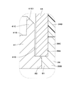
- It is sectional drawing which shows the state which assembled the storage member (housing), the joining member (cylinder) and the stator (yoke).
- It is an enlarged sectional view of the part (V) in FIG.
- FIG. 5 shows the storage member, the joining member, etc. by the 1st modification.
- FIG. 3 is an enlarged cross-sectional view showing a joint portion between a stator (yoke, anchor) and a joint member according to a third modification.
- the damping force adjusting type hydraulic shock absorber 1 (hereinafter referred to as hydraulic shock absorber 1) includes a damping force adjusting mechanism 17 having a solenoid 33 as a drive source. That is, the hydraulic shock absorber 1 as a damping force adjusting shock absorber includes an outer cylinder 2, an inner cylinder 4 as a cylinder, a piston 5, a piston rod 8, a rod guide 9, and a damping force adjusting mechanism 17. It is configured to include.
- the hydraulic shock absorber 1 is provided with a bottomed tubular outer cylinder 2 forming an outer shell.
- the lower end side of the outer cylinder 2 is closed by the bottom cap 3 using a welding means or the like.
- the upper end side of the outer cylinder 2 is a crimped portion 2A bent inward in the radial direction.
- a rod guide 9 and a sealing member 10 are provided between the caulking portion 2A and the inner cylinder 4.
- an opening 2B is formed concentrically with the connection port 12C of the intermediate cylinder 12.
- a damping force adjusting mechanism 17 is attached to the lower side of the outer cylinder 2 so as to face the opening 2B.
- the bottom cap 3 is provided with a mounting eye 3A that is mounted on the wheel side of the vehicle, for example.
- the inner cylinder 4 is provided coaxially with the outer cylinder 2.
- the lower end side of the inner cylinder 4 is fitted and attached to the bottom valve 13.
- the upper end side of the inner cylinder 4 is fitted and attached to the rod guide 9.
- An oil liquid as a working fluid (working fluid) is sealed in the inner cylinder 4 as a cylinder.
- the hydraulic fluid is not limited to oil and oil, and may be, for example, water mixed with additives.
- An annular reservoir chamber A is formed between the inner cylinder 4 and the outer cylinder 2. Gas is sealed in the reservoir chamber A together with the oil liquid. This gas may be air in an atmospheric pressure state, or a gas such as compressed nitrogen gas may be used. The reservoir chamber A compensates for the entry and exit of the piston rod 8.
- An oil hole 4A that allows the rod-side oil chamber B to always communicate with the annular oil chamber D is bored in the radial direction at an intermediate position in the length direction (axial direction) of the inner cylinder 4.
- the piston 5 is slidably inserted into the inner cylinder 4. That is, the piston 5 is slidably provided in the inner cylinder 4.
- the piston 5 defines (partitions) the inside of the inner cylinder 4 into two chambers, a rod-side oil chamber B and a bottom-side oil chamber C.
- a plurality of oil passages 5A and 5B that allow the rod-side oil chamber B and the bottom-side oil chamber C to communicate with each other are formed in the piston 5 so as to be separated from each other in the circumferential direction.
- a disc valve 6 on the extension side is provided on the lower end surface of the piston 5.
- the disc valve 6 on the extension side opens when the pressure in the oil chamber B on the rod side exceeds the relief set pressure when the piston 5 slides and displaces upward in the extension stroke of the piston rod 8, and the pressure at this time. Is relieved to the bottom side oil chamber C side via each oil passage 5A.
- the relief set pressure is set to a pressure higher than the valve opening pressure when the damping force adjusting mechanism 17 is set hard.
- a contraction-side check valve 7 is provided on the upper end surface of the piston 5 to open the valve when the piston 5 slides and displaces downward in the contraction stroke of the piston rod 8, and closes the valve at other times.
- the check valve 7 allows the oil liquid in the bottom side oil chamber C to flow in each oil passage 5B toward the rod side oil chamber B, and prevents the oil liquid from flowing in the opposite direction. ..
- the valve opening pressure of the check valve 7 is set to a pressure lower than the valve opening pressure when the damping force adjusting mechanism 17 is softly set, and substantially no damping force is generated. The fact that this substantially no damping force is generated is a force equal to or less than the friction of the piston 5 and the seal member 10, and does not affect the motion of the vehicle.
- the piston rod 8 extends in the inner cylinder 4 in the axial direction (upper and lower directions in FIG. 1).
- the lower end side of the piston rod 8 is inserted into the inner cylinder 4.
- the piston rod 8 is provided so as to be fixed to the piston 5 by a nut 8A or the like.
- the upper end side of the piston rod 8 projects to the outside of the outer cylinder 2 and the inner cylinder 4 via the rod guide 9. That is, the piston rod 8 is connected to the piston 5 and extends to the outside of the inner cylinder 4.
- the lower end of the piston rod 8 may be further extended so as to project outward from the bottom portion (for example, the bottom cap 3) side to form so-called both rods.
- a stepped cylindrical rod guide 9 is provided on the upper end side of the inner cylinder 4.
- the rod guide 9 positions the upper portion of the inner cylinder 4 at the center of the outer cylinder 2 and guides the piston rod 8 so as to be slidable in the axial direction on the inner peripheral side thereof.
- An annular sealing member 10 is provided between the rod guide 9 and the crimped portion 2A of the outer cylinder 2.
- the seal member 10 is configured by, for example, baking an elastic material such as rubber on a metal annular plate provided with a hole through which the piston rod 8 is inserted in the center.
- the sealing member 10 seals between the elastic material and the piston rod 8 by the inner circumference of the elastic material sliding in contact with the outer peripheral side of the piston rod 8.
- the seal member 10 is formed with a lip seal 10A as a check valve extending so as to come into contact with the rod guide 9 on the lower surface side.
- the lip seal 10A is arranged between the oil reservoir 11 and the reservoir chamber A.
- the lip seal 10A allows the oil liquid or the like in the oil reservoir 11 to flow toward the reservoir chamber A side through the return passage 9A of the rod guide 9, and blocks the flow in the opposite direction.
- An intermediate cylinder 12 made of a cylinder is arranged between the outer cylinder 2 and the inner cylinder 4.
- the intermediate cylinder 12 is attached to, for example, on the outer peripheral side of the inner cylinder 4 via upper and lower tubular seals 12A and 12B.
- the intermediate cylinder 12 has an annular oil chamber D extending inside so as to surround the outer peripheral side of the inner cylinder 4 over the entire circumference.
- the annular oil chamber D is an oil chamber independent of the reservoir chamber A.
- the annular oil chamber D is always in communication with the rod side oil chamber B by the radial oil hole 4A formed in the inner cylinder 4.
- the annular oil chamber D is a flow path in which the working liquid flows due to the movement of the piston rod 8.
- a connection port 12C to which the connection pipe body 20 of the damping force adjusting valve 18 is attached is provided on the lower end side of the intermediate cylinder 12.
- the bottom valve 13 is located on the lower end side of the inner cylinder 4 and is provided between the bottom cap 3 and the inner cylinder 4.
- the bottom valve 13 has a valve body 14 that defines (partitions) the reservoir chamber A and the bottom side oil chamber C between the bottom cap 3 and the inner cylinder 4, and a reduction side provided on the lower surface side of the valve body 14.
- the disc valve 15 and the extension side check valve 16 provided on the upper surface side of the valve body 14 are configured.
- the valve body 14 is formed with oil passages 14A and 14B that allow the reservoir chamber A and the bottom side oil chamber C to communicate with each other at intervals in the circumferential direction.
- the disc valve 15 on the reduction side opens when the pressure in the oil chamber C on the bottom side exceeds the relief set pressure when the piston 5 slides and displaces downward in the reduction stroke of the piston rod 8, and the pressure at this time. Is relieved to the reservoir chamber A side via each oil passage 14A.
- the relief set pressure is set to a pressure higher than the valve opening pressure when the damping force adjusting mechanism 17 is set hard.
- the extension-side check valve 16 opens when the piston 5 slides and displaces upward in the extension stroke of the piston rod 8, and closes at other times.
- the check valve 16 allows the oil liquid in the reservoir chamber A to flow in each oil passage 14B toward the bottom side oil chamber C, and prevents the oil liquid from flowing in the opposite direction.
- the valve opening pressure of the check valve 16 is set to a pressure lower than the valve opening pressure when the damping force adjusting mechanism 17 is softly set, and substantially no damping force is generated.
- the damping force adjusting mechanism 17 controls the flow of the working liquid generated by the sliding of the piston 5 in the cylinder (inner cylinder 4) to generate a damping force, and variably adjusts the generated damping force of the hydraulic shock absorber 1. It is a mechanism.
- the amateur 48 actuating pin 49
- FIG. 2 shows a state in which the pilot valve body 32 has moved to the left side (that is, the valve closing direction in which the pilot valve body 32 is seated on the valve seat portion 26E of the pilot body 26).
- the damping force adjusting mechanism 17 is arranged so that its base end side (left end side in FIG. 1) is interposed between the reservoir chamber A and the annular oil chamber D, and the tip end side (FIG. 1). The right end side) is provided so as to project outward in the radial direction from the lower side of the outer cylinder 2.
- the damping force adjusting mechanism 17 generates a damping force by controlling the flow of the oil liquid from the annular oil chamber D to the reservoir chamber A by the damping force adjusting valve 18. Further, the generated damping force is variably adjusted by adjusting the valve opening pressure of the damping force adjusting valve 18 with the solenoid 33 used as the damping force variable actuator. In this way, the damping force adjusting mechanism 17 controls the flow of the working fluid (oil liquid) generated by the sliding of the piston 5 in the inner cylinder 4 to generate the damping force.
- the damping force adjusting mechanism 17 includes a damping force adjusting valve 18 that generates a damping force having hard or soft characteristics by variably controlling the flow of oil liquid from the annular oil chamber D to the reservoir chamber A, and a damping force adjusting valve. It is configured to include a solenoid 33 for adjusting the operation of the on-off valve of 18. That is, the valve opening pressure of the damping force adjusting valve 18 is adjusted by the solenoid 33 used as the damping force variable actuator, whereby the generated damping force is variably controlled to a hard or soft characteristic.
- the damping force adjusting valve 18 is a valve whose on-off valve operation is adjusted by a solenoid 33, and is a flow path (for example, between the annular oil chamber D and the reservoir chamber A) where the flow of the working liquid is generated by the movement of the piston rod 8. It is provided in.
- the damping force adjusting valve 18 has a substantially cylindrical valve case 19 provided so that the base end side thereof is fixed around the opening 2B of the outer cylinder 2 and the tip end side protrudes radially outward from the outer cylinder 2.
- the connection tube 20 is fixed to the connection port 12C of the intermediate cylinder 12 on the base end side, and the tip side is an annular flange portion 20A, which is arranged inside the valve case 19 with a gap, and the connection tube body 20. It is configured to include a valve member 21 that abuts on the flange portion 20A.
- the base end side of the valve case 19 is an annular inner flange portion 19A extending inward in the radial direction.
- the tip end side of the valve case 19 is a male screw portion 19B into which a lock nut 53 for connecting the valve case 19 and the yoke 39 (one-side cylinder portion 39G) of the solenoid 33 is screwed.
- An annular oil that always communicates with the reservoir chamber A between the inner peripheral surface of the valve case 19 and the outer peripheral surface of the valve member 21, and further between the inner peripheral surface of the valve case 19 and the outer peripheral surface of the pilot body 26 or the like. Room 19C.
- the valve case 19 and the solenoid 33 are connected by a locknut 53, or may be configured such that the tip end side of the valve case is crimped to the yoke of the solenoid (a configuration that does not use a locknut).
- an oil passage 20B that communicates with the annular oil chamber D and the other side extends to the position of the valve member 21.
- an annular spacer 22 is provided in a sandwiched state between the flange portion 20A of the connecting pipe body 20 and the inner flange portion 19A of the valve case 19.
- the spacer 22 is provided with a plurality of notches 22A that serve as radial oil passages so as to communicate with the oil chamber 19C and the reservoir chamber A so as to extend radially.
- the spacer 22 is provided with a notch 22A for forming an oil passage.
- notches for forming an oil passage may be provided radially in the inner flange portion 19A of the valve case 19. With this configuration, the spacer 22 can be omitted and the number of parts can be reduced.
- the valve member 21 is provided with a central hole 21A located at the center in the radial direction and extending in the axial direction. Further, the valve member 21 is provided with a plurality of oil passages 21B around the central hole 21A so as to be spaced apart from each other in the circumferential direction. One side (left side of FIGS. 1 and 2) of each oil passage 21B is always in communication with the oil passage 20B side of the connecting pipe body 20. Further, on the end surface of the other side (right side of FIGS. 1 and 2) of the valve member 21, an annular recess 21C formed so as to surround the other side opening of the oil passage 21B and a radial outer side of the annular recess 21C.
- each oil passage 21B of the valve member 21 is a main valve between the oil passage 20B of the connecting pipe body 20 communicating with the annular oil chamber D and the oil chamber 19C of the valve case 19 communicating with the reservoir chamber A. It becomes a flow path through which the pressure oil of the flow rate corresponding to the opening degree of 23 flows.
- the main valve 23 is composed of a disc valve whose inner peripheral side is sandwiched between the valve member 21 and the large diameter portion 24A of the pilot pin 24.
- the outer peripheral side of the main valve 23 is taken off and seated on the annular valve seat 21D of the valve member 21.
- An elastic seal member 23A is fixed to the outer peripheral portion on the back surface side of the main valve 23 by means such as baking.
- the main valve 23 is opened by receiving the pressure on the oil passage 21B side (annular oil chamber D side) of the valve member 21 and separating from the annular valve seat 21D.
- the oil passage 21B (annular oil chamber D side) of the valve member 21 is communicated with the oil chamber 19C (reservoir chamber A side) via the main valve 23, and the amount of pressure oil flowing in the arrow Y direction at this time. (Flow rate) is variably adjusted according to the opening degree of the main valve 23.
- the pilot pin 24 is formed in a stepped cylindrical shape, and an annular large diameter portion 24A is provided in the intermediate portion in the axial direction.
- the pilot pin 24 has a central hole 24B extending in the axial direction on the inner peripheral side.
- a small diameter hole (orifice 24C) is formed at one end of the central hole 24B (the end on the connecting tube body 20 side).
- One end side (left end side of FIGS. 1 and 2) of the pilot pin 24 is press-fitted into the center hole 21A of the valve member 21, and the main valve 23 is sandwiched between the large diameter portion 24A and the valve member 21.
- the other end side of the pilot pin 24 (the right end side of FIGS. 1 and 2) is fitted in the center hole 26C of the pilot body 26.
- an oil passage 25 extending in the axial direction is formed between the center hole 26C of the pilot body 26 and the other end side of the pilot pin 24.
- the oil passage 25 communicates with a back pressure chamber 27 formed between the main valve 23 and the pilot body 26.
- a plurality of oil passages 25 extending in the axial direction are provided on the side surface on the other end side of the pilot pin 24 in the circumferential direction, and the other peripheral positions are press-fitted into the central hole 26C of the pilot body 26.
- the pilot body 26 is formed as a substantially bottomed tubular body, and has a cylindrical portion 26A having a stepped hole formed inside and a bottom portion 26B that closes the cylindrical portion 26A.
- the bottom portion 26B of the pilot body 26 is provided with a center hole 26C into which the other end side of the pilot pin 24 is fitted.
- a protruding cylinder portion 26D located on the outer diameter side and protruding toward the valve member 21 over the entire circumference is integrally provided. ..
- the elastic sealing member 23A of the main valve 23 is liquid-tightly fitted to the inner peripheral surface of the protruding cylinder portion 26D, thereby forming a back pressure chamber 27 between the main valve 23 and the pilot body 26. ing.
- the back pressure chamber 27 generates a pressure (internal pressure, pilot pressure) that presses the main valve 23 in the valve closing direction, that is, in the direction in which the main valve 23 is seated on the annular valve seat 21D of the valve member 21.
- a valve seat portion 26E on which the pilot valve body 32 takes off and sits is provided so as to surround the central hole 26C. Further, inside the cylindrical portion 26A of the pilot body 26, when the return spring 28 for urging the pilot valve body 32 in the direction away from the valve seat portion 26E of the pilot body 26 and the solenoid 33 are in a non-energized state (pilot valve body).
- a disc valve 29 constituting a fail-safe valve (when 32 is farthest from the valve seat portion 26E), a holding plate 30 having an oil passage 30A formed on the center side, and the like are arranged.
- a cap 31 is fitted and fixed to the open end of the cylindrical portion 26A of the pilot body 26 with a return spring 28, a disc valve 29, a holding plate 30, and the like arranged inside the cylindrical portion 26A.
- the cap 31 is formed with notches 31A at four positions separated from each other in the circumferential direction, for example. As shown by the arrow X in FIG. 2, the notch 31A is a flow path for flowing the oil liquid flowing to the solenoid 33 side through the oil passage 30A of the holding plate 30 to the oil chamber 19C (reservoir chamber A side). ..
- the pilot valve body 32 constitutes a pilot valve (control valve) together with the pilot body 26.
- the pilot valve body 32 is formed in a stepped cylindrical shape.
- the tip of the pilot valve body 32 that is, the tip of the pilot body 26 that takes off and sits on the valve seat portion 26E, has a tapered shape.
- An actuating pin 49 of the solenoid 33 is fitted and fixed inside the pilot valve body 32, and the valve opening pressure of the pilot valve body 32 is adjusted according to the energization of the solenoid 33.
- the pilot valve (pilot body 26 and pilot valve body 32) as a control valve is controlled by the movement of the actuating pin 49 (that is, the amateur 48) of the solenoid 33.
- a flange portion 32A serving as a spring receiver is formed on the proximal end side of the pilot valve body 32 over the entire circumference.
- the flange portion 32A comes into contact with the inner peripheral portion of the disc valve 29 when the solenoid 33 is in a non-energized state, that is, when the pilot valve body 32 is displaced to the fully open position farthest from the valve seat portion 26E. It constitutes a fail-safe valve.
- FIGS. 3 to 5 the reference numerals are given with the right side of FIG. 2 facing upward. That is, the left and right directions of FIGS. 1 and 2 correspond to the upper and lower directions of FIGS. 3 to 5.
- the solenoid 33 is incorporated in the damping force adjusting mechanism 17 as a damping force variable actuator of the damping force adjusting mechanism 17. That is, the solenoid 33 is used in the damping force adjusting type shock absorber to adjust the operation of the on-off valve of the damping force adjusting valve 18.
- the solenoid 33 includes a mold coil 34, a housing 36 as a storage member, a yoke 39 as a stator, an anchor 41 as a stator, a cylinder 44 as a joining member (non-magnetic ring), and a mover (movable). It includes an amateur 48 as an iron core), an actuating pin 49, and a cover member 51.
- the housing (core 74) and the yoke (solenoid case 71) are connected via a joining member (unsigned).
- the housing (core 74) has a small diameter portion (unsigned) to which the joining member (unsigned) fits, and a large diameter portion (unsigned) having a larger outer diameter than the small diameter portion.
- a notch (unsigned) for storing the brazing filler metal is provided between the small diameter portion and the large diameter portion.
- a protrusion (unsigned) protruding toward the inner diameter side is provided on the inside (inner surface) of the joining member (unsigned). It is considered that the edge of the housing (core 74) on the opening side abuts on this protrusion, whereby the housing (core 74) is aligned (positioned in the axial direction).
- the solenoid has three functions: "storing the brazing material between the housing and the joining member”, “correctly aligning the housing", and “transferring magnetic flux to the mover". It is preferable that the function can be ensured and the cost of the joining member (unsigned) can be reduced. It is also preferable that the thrust characteristics of the solenoid (movable element) can be improved while shortening the axial length of the solenoid.
- the material cost and processing cost of the joining member are due to the provision of the protrusion (unsigned) as a shoulder inside the joining member (unsigned). May increase. Further, since the protrusion (unsigned) is present inside the joining member (unsigned), the degree of freedom in designing the distance between the housing (core 74) and the corner portion (unsigned) of the stator (core 73) is low. There is a possibility that it will be. This may lead to an increase in the shaft length of the solenoid and a decrease in thrust characteristics.
- three end portions 36D, 36E, and 36F are formed on the storage cylinder portion 36A (small diameter cylinder portion 36C) of the housing 36. Is provided.
- the end 36F located on the upper side in the vertical direction in FIGS. 4 and 5 is a brazing material (copper) when the housing 36 and the cylinder 44 are assembled. It constitutes a brazing material storage part for installing a ring).
- the end portion 36E located in the middle in the vertical direction in FIGS.
- the lower end (first end 36D) in the vertical direction in FIGS. 4 and 5 is the position where the housing 36 is held by the intermediate end 36E (second end 36E) that serves as a position fixing portion.
- a magnetic flux transfer unit for transferring magnetic flux to and from the amateur 48 is configured.
- the holding member (cylinder) is provided with a position holding function (alignment function), whereas in the embodiment, the position holding function (alignment function) is provided. Is changed from the holding member (cylinder) to the housing 36.
- the cylinder 44 can be a simple cylinder. Therefore, the material cost and the processing cost of the cylinder 44 can be reduced, and the degree of freedom in designing the distance between the housing 36 and the protruding portion 41C which is the corner portion of the anchor 41 can be improved.
- the shape of the housing 36 and the shape of the cylinder 44 are only changed as compared with the prior art, it is possible to reduce the influence on the axial length and the thrust characteristics of the solenoid 33. Therefore, in the embodiment, the thrust characteristics of the solenoid 33 (amateur 48) can be improved while shortening the axial length of the solenoid 33.
- the solenoid 33 of the present embodiment provided with such a housing 36 and a cylinder 44 will be described with reference to FIGS. 2 to 5.
- the solenoid 33 includes a mold coil 34, a housing 36, a yoke 39, an anchor 41, a cylinder 44, an amateur 48, and an actuating pin 49.
- the mold coil 34 is formed in a substantially cylindrical shape by integrally covering (molding) the coil 34A with a resin member 34C such as a thermosetting resin in a state where the coil 34A is wound around the coil bobbin 34B. ..
- a cable take-out portion 34E protruding outward in the axial direction or the radial direction is provided in a part of the circumferential direction of the mold coil 34, and an electric wire cable (not shown) is connected to the cable take-out portion 34E.
- the coil 34A of the mold coil 34 is wound in an annular shape around the coil bobbin 34B, and becomes an electromagnet to generate a magnetic force by supplying electric power (energization) through a cable from the outside.
- a seal groove 34D is formed over the entire circumference on the side surface (end surface on one side in the axial direction) facing the yoke 39 (annular portion 39B).
- a seal member for example, an O-ring 35
- the O-ring 35 tightly seals between the mold coil 34 and the yoke 39 (annular portion 39B). This makes it possible to prevent dust including rainwater and muddy water from entering the tubular protrusion 39C side of the yoke 39 via between the yoke 39 and the mold coil 34.
- the coil used in this embodiment is not limited to the molded coil 34 composed of the coil 34A, the coil bobbin 34B, and the resin member 34C, and other coils may be used.
- the outer periphery of the coil may be covered with an overmold (not shown) obtained by molding a resin material from above (outer peripheral side).
- the housing 36 constitutes a first fixed iron core (storage member) arranged and provided on the inner peripheral side of the mold coil 34 (that is, the inner circumference of the coil 34A).
- the housing 36 is formed as a covered cylindrical cylinder by a magnetic material (magnetic material) such as low carbon steel or carbon steel for machine structure (S10C).
- the housing 36 has a storage cylinder portion 36A as a storage portion that extends in the winding axis direction of the mold coil 34 (coil 34A) and has one end side (left side in FIG. 2, lower side in FIGS. 3 to 5) open.
- the outer circumference of the storage cylinder portion 36A is covered by a stepped lid portion 36B that closes the other end side (right side of FIG. 2, upper side of FIGS. 3 to 5) and an opening side (one side) of the storage cylinder portion 36A. It is configured to include a small diameter cylinder portion 36C for joining formed so as to reduce the diameter.
- the inner circumference of the cylinder 44 is joined to the outer circumference of the small diameter cylinder portion 36C of the housing 36 by brazing.
- the inner diameter of the storage cylinder portion 36A of the housing 36 is formed to be slightly larger than the outer diameter of the amateur 48, and the amateur 48 is housed in the storage cylinder portion 36A so as to be movable in the axial direction. That is, the housing 36 is open at one end side in the axial direction, and the amateur 48 is housed in the housing 36.
- the storage cylinder portion 36A of the housing 36 has the first end portion 36D, the second end portion 36E, in order from the inner circumference of the open end (in order from the inner diameter side to the outer diameter side). And it has a third end 36F.
- the first end portion 36D faces the anchor 41, more specifically, the protruding portion 41C (diameter reduced portion 41C1) of the anchor 41.
- the second end portion 36E has an abutting portion 36E1 that is recessed in the axial direction with respect to the first end portion 36D and abuts on the other end 44A in the axial direction of the cylinder 44.
- the third end portion 36F is recessed from the second end portion 36E in the axial direction with respect to the first end portion 36D, and a brazing material (copper ring) for sealing between the third end portion 36F and the cylinder 44 is housed. That is, between the third end portion 36F and the other end 44A of the cylinder 44, there is a brazing filler metal storage portion 45 in which the brazing filler metal is stored.
- the end portions 36D, 36E, 36F having three steps are provided on the open end side (lower side of FIGS. 3 to 5) of the housing 36.
- the third end portion 36F constitutes a brazing filler metal storage portion 45 with the other end 44A of the cylinder 44.
- the second end portion 36E (contact portion 36E1) constitutes a position fixing portion for aligning (positioning) the housing 36 by abutting with the other end 44A of the cylinder 44.
- the first end portion 36D constitutes a magnetic flux transfer portion. As shown in FIG. 5, the first end portion 36D has an inclined surface 36D1 formed on the outer diameter side. That is, the first end portion 36D has an inclined surface 36D1 inclined in a direction in which the outer diameter dimension increases toward the other side in the axial direction.
- the inclined surface 36D1 can be used as a guide when the small diameter cylinder portion 36C of the housing 36 is inserted into the cylinder 44.
- the housing 36 and the cylinder 44 form a pressure vessel by press-fitting the housing 36 (small diameter cylinder portion 36C) into the inside of the cylinder 44 and brazing. Therefore, the outer diameter of the small diameter cylinder portion 36C of the housing 36 is larger than the inner diameter of the cylinder 44 (has a tightening allowance).
- the housing 36 (small diameter cylinder portion 36C) is press-fitted into the cylinder 44 until the second end portion 36E (contact portion 36E1) and the other end 44A of the cylinder 44 come into contact with each other.
- Brazing can be performed by installing a brazing material (copper ring) in the brazing material storage portion 45 between the third end portion 36F and the other end 44A of the cylinder 44.
- the lid portion 36B of the housing 36 is integrally formed with the storage cylinder portion 36A as a covered cylinder that closes the storage cylinder portion 36A from the other side in the axial direction.
- the outer diameter of the lid portion 36B has a stepped shape smaller than the outer diameter of the storage cylinder portion 36A, and the fitting cylinder portion 51A of the cover member 51 is fitted and provided on the outer peripheral side of the lid portion 36B.
- the housing 36 is formed with a bottomed stepped hole 37 located inside the lid portion 36B.
- the stepped hole 37 includes a bush mounting hole portion 37A and a small diameter hole portion 37B located on the back side of the bush mounting hole portion 37A and formed to have a small diameter.
- a first bush 38 for slidably supporting the actuating pin 49 is provided in the bush mounting hole 37A.
- the lid portion 36B of the housing 36 is arranged so that the other side end faces face the lid plate 51B of the cover member 51 with a gap in the axial direction.
- This axial gap has a function of preventing an axial force from being directly applied to the housing 36 from the lid plate 51B side of the cover member 51 via the lid portion 36B.
- the lid portion 36B of the housing 36 does not necessarily have to be integrally formed of the same material (magnetic material) as the storage cylinder portion 36A.
- the lid portion 36B can be formed of, for example, a rigid metal material, a ceramic material, or a fiber-reinforced resin material instead of the magnetic material.
- the joint between the storage cylinder portion 36A and the lid portion 36B of the hugging 36 is set at a position in consideration of the transfer of magnetic flux.
- the yoke 39 is provided on one side of the amateur 48 in the moving direction.
- the yoke 39 is a magnetic member that together with the housing 36 forms a magnetic circuit (magnetic path) over the inner peripheral side and the outer peripheral side of the mold coil 34 (coil 34A).
- the yoke 39 is formed by using a magnetic material (magnetic material) like the housing 36, extends radially on one side in the axial direction (one side in the winding axis direction) of the mold coil 34 (coil 34A), and the yoke 39 thereof extends in the radial direction.
- the tubular protrusion 39C constitutes a protrusion (cylinder portion) for joining with the cylinder 44, and the cylinder 44 is inserted on the inner diameter side of the tubular protrusion 39C.
- the yoke 39 has a fixing hole 39A, and the inner peripheral surface of the fixing hole 39A faces a part of the side surface portion 41D of the anchor 41. Further, in the fixing hole 39A, an inward flange portion 39D protruding toward the inner diameter side is provided over the entire circumference. An end surface (one end surface) on one side in the axial direction of the cylinder 44 is in contact with the side surface (side surface on the coil 34A side) of the inward flange portion 39D.
- the outer periphery of the cylinder 44 on one axial direction is fitted to the inner circumference of the yoke 39, that is, the inner surface of the fixing hole 39A (in other words, the inner peripheral surface of the tubular protrusion 39C).
- the yoke 39 has a cylindrical one-sided tubular portion 39G extending from the outer peripheral side of the annular portion 39B toward one side in the axial direction (damping force adjusting valve 18 side) and the other side in the axial direction from the outer peripheral side of the annular portion 39B.
- the other side cylinder portion 39H extending toward (cover member 51 side) and surrounding the mold coil 34 from the radial outside, and the flange portion of the cover member 51 provided on the tip end side of the other side cylinder portion 39H. It is formed as an integral body including a caulking portion 39J that holds 51C in a retaining state.
- the other side cylinder portion 39H of the yoke 39 is provided with a notch 39K for exposing the cable extraction portion 34E of the mold coil 34 to the outside of the other side cylinder portion 39H.
- an engagement recess 39L having a semicircular cross section so as to open on the outer peripheral surface of the yoke 39 is provided (over the entire circumference or in the circumferential direction). It is provided in multiple places) apart from each other.
- a lock nut 53 screwed to the valve case 19 of the damping force adjusting valve 18 is engaged with the engaging recess 39L via a retaining ring 54 (see FIG. 2).
- a seal groove 39M is provided on the outer peripheral surface of the one-side cylinder portion 39G over the entire circumference.
- An O-ring 40 (see FIG. 2) as a sealing member is mounted on the sealing groove 39M. The O-ring 40 tightly seals between the yoke 39 (one-side cylinder portion 39G) and the valve case 19 of the damping force adjusting valve 18.
- the anchor 41 is provided on one side of the amateur 48 in the moving direction.
- the anchor 41 is a second fixed iron core (stator) fixed in the fixing hole 39A of the yoke 39 by means such as press fitting.
- the anchor 41 fills the fixing hole 39A of the yoke 39 from the inside with a magnetic material (magnetic material) such as low carbon steel and carbon steel for machine structure (S10C) like the housing 36 (first fixed iron core) and the yoke 39. It is formed in a shape.
- the anchor 41 is formed as a short cylindrical annular body having a through hole 41A whose central side extends in the axial direction.
- One side surface of the anchor 41 in the axial direction (the surface facing the cap 31 of the damping force adjusting valve 18 shown in FIG. 2 in the axial direction) is formed so as to be a flat surface like one side surface of the annular portion 39B of the yoke 39. ing.
- a circular concave recess 41B is recessed on the other side of the anchor 41 in the axial direction (the other side surface facing the amateur 48 in the axial direction) so as to be coaxial with the storage cylinder portion 36A.
- the recessed portion 41B is formed as a circular groove having a diameter slightly larger than that of the amateur 48 so that the amateur 48 can be inserted into and out of the recessed portion 41B by a magnetic force.
- a cylindrical protrusion 41C is provided on the other side of the anchor 41.
- the outer peripheral surface of the protrusion 41C on the opening side is formed as a conical surface so that the magnetic characteristic is linear between the anchor 41 and the amateur 48.
- the protruding portion 41C which is also called a corner portion, protrudes in a cylindrical shape from the outer peripheral side of the anchor 41 toward the other side in the axial direction.
- the outer peripheral surface (outer peripheral surface on the opening side) of the protrusion 41C is a conical surface inclined in a tapered shape so that the outer diameter dimension gradually decreases toward the other side (opening side) in the axial direction. ..
- the protruding portion 41C of the anchor 41 is provided at a position facing the opening (more specifically, the first end portion 36D) of the housing 36 (storage cylinder portion 36A), and is provided in the opening of the storage cylinder portion 36A. It has a reduced diameter portion 41C1 whose outer diameter is reduced as it approaches.
- a side surface portion 41D extending in a direction away from the opening of the storage cylinder portion 36A of the housing 36 is formed along the outer peripheral side of the protruding portion 41C.
- the end portion of the side surface portion 41D on the side away from the opening is an annular flange portion 41E protruding outward in the radial direction.
- the annular flange portion 41E is arranged at a position largely separated from the opening end of the storage cylinder portion 36A of the housing 36 on one side in the axial direction (that is, the end portion on the side opposite to the recessed portion 41B).
- the annular flange portion 41E is fixed in the fixing hole 39A of the yoke 39 by means such as press fitting.
- the annular flange portion 41E is a fixing portion of the anchor 41 (side surface portion 41D) with respect to the fixing hole 39A of the yoke 39, and is also a portion where the flange portion 41E and the fixing hole 39A face each other in the radial direction.
- the side surface portion 41D (excluding the annular flange portion 41E) of the anchor 41 faces the inner peripheral surface of the cylinder 44 and the inner surface of the inward flange portion 39D of the yoke 39 via a gap (diameter gap).
- the protruding portion 41C and the side surface portion 41D are integrally formed by a magnetic material.
- the anchor 41 is provided at a position facing the opening of the storage cylinder portion 36A of the housing 36.
- the protruding portion 41C projects toward the opening of the storage cylinder portion 36A of the housing 36.
- the side surface portion 41D extends from the outer periphery of the protruding portion 41C in a direction away from the opening of the storage cylinder portion 36A of the housing 36.
- the side surface portion 41D has a gap with respect to the inner peripheral surface of the cylinder 44 and the inner surface of the inward flange portion 39D of the yoke 39.
- a second bush 43 for slidably supporting the actuating pin 49 is fitted in the stepped through hole 41A formed on the center (inner circumference) side of the anchor 41. It is provided.
- a pilot body 26 of the damping force adjusting valve 18, a return spring 28, a disc valve 29, a holding plate 30, a cap 31, and the like are provided on the inner peripheral side of the one-side cylinder portion 39G of the yoke 39. It is provided by inserting it. Further, the valve case 19 of the damping force adjusting valve 18 is fitted (outerly fitted) on the outer peripheral side of the one-side cylinder portion 39G.
- the cylinder 44 is provided between the yoke 39 and the anchor 41 in the radial direction. Further, the cylinder 44 is provided between the yoke 39 and the housing 36 in the axial direction and the radial direction. That is, the cylinder 44 is a non-magnetic connecting member (cylinder 34A) located on the inner peripheral side of the mold coil 34 (coil 34A) located between the small diameter tubular portion 36C of the housing 36 and the tubular protrusion 39C of the yoke 39. Joining member).
- the cylinder 44 is made of a non-magnetic material. More specifically, the cylinder 44 is formed as a cylinder (simple cylinder) by a non-magnetic material such as austenitic stainless steel.
- the outer circumference of the mold coil 34 (coil 34A) on one end side (yoke 39 side) in the winding axis direction is joined to the inner circumference of the yoke 39 (fixing hole 39A, tubular protrusion 39C).
- the cylinder 44 is fixed to the yoke 39 having a stator on one side in the axial direction.
- the inner circumference of the other end side (housing 36 side) of the mold coil 34 (coil 34A) in the winding axis direction is joined to the outer circumference of the housing 36 (small diameter cylinder portion 36C).
- the cylinder 44 is fitted (press-fitted) to the outside (outer peripheral side) of the small-diameter cylinder portion 36C of the housing 36, and both are joined by brazing.
- the other end 44A of the cylinder 44 is in contact with the second end portion 36E (contact portion 36E1) of the small diameter cylinder portion 36C of the housing 36.
- the cylinder 44 is fitted (press-fitted) to the inside (inner peripheral side) of the tubular protrusion 39C of the yoke 39, and both are joined by brazing.
- one end of the cylinder 44 is in contact with the side surface of the inward flange portion 39D of the yoke 39.
- the cylinder 44, the housing 36, and the yoke 39 are press-fitted into the cylinder 44 and the housing 36, and the cylinder 44 and the yoke 39 are press-fitted to assemble them, and then brazing and joining are performed.
- the housing 36 and the cylinder 44, and the cylinder 44 and the yoke 39 are joined via a brazing material.
- the brazing filler metal for example, pure copper brazing filler metal can be used. That is, the brazing can be performed by, for example, a brazing treatment at 1000 ° C. or higher using a brazing material (copper ring) made of pure copper brazing.
- the brazing material may be other than pure copper brazing. For example, brass brazing, nickel brazing, gold brazing, palladium brazing and the like may be used.
- the cylinder 44 is joined to the small-diameter cylinder portion 36C of the housing 36 and the tubular protrusion portion 39C of the yoke 39 by brazing. After the brazing process, a quenching process is performed. In this state, the inner diameter of the cylinder 44 is formed to be larger than the outer diameter of the side surface portion 41D of the anchor 41.
- the cylinder 44, the yoke 39, and the housing 36 are made of materials having different coefficients of linear expansion.
- the cylinder 44 is made of stainless steel and the housing 36 is made of carbon steel for machine structure (S10C).
- S10C machine structure
- the stainless steel cylinder 44 having a large coefficient of linear expansion expands more than the housing 36, and the inner circumference of the other end side of the cylinder 44
- the brazing material can be stored in the gap formed between the housing 36 (small diameter cylinder portion 36C) and the outer periphery thereof.
- the brazing material stored in the brazing material storage portion 45 between the third end portion 36F of the housing 36 and the other end 44A of the cylinder 44 is placed on the inner circumference of the other end side of the cylinder 44 and the housing 36 (small diameter cylinder portion 36C).
- the sealing property between the cylinder 44 and the housing 36 (small diameter cylinder portion 36C) can be improved.
- a non-contact portion may be provided between the outer periphery of the cylinder 44 and the inner circumference of the yoke 39 (inner surface of the fixing hole 39A, inner peripheral surface of the tubular protrusion 39C).
- a small diameter hole portion having a smaller inner diameter dimension and a smaller diameter hole portion than the small diameter hole portion.
- a large-diameter hole having a large inner diameter can be provided.
- the cylinder 44 Even if the stainless steel cylinder 44 having a large coefficient of linear expansion tends to expand more than the yoke 39 when the temperatures of the cylinder 44 and the yoke 39 rise due to brazing, the cylinder 44
- the brazing material can be stored in the non-contact portion between the outer periphery and the inner circumference of the yoke 39 (inner surface of the fixing hole 39A, inner peripheral surface of the tubular protrusion 39C). Thereby, the sealing property between the cylinder 44 and the yoke 39 (fixing hole 39A) can be improved.
- the joining between the cylinder 44 and the housing 36 and / or the joining between the cylinder 44 and the yoke 39 is performed by heating with a joining means other than brazing (for example, a joining means by welding such as laser welding). It may be a configuration. That is, the housing 36 and the cylinder 44, and the cylinder 44 and the yoke 39 may be joined by welding.
- the amateur 48 is a mover made of a magnetic material provided between the storage cylinder portion 36A of the housing 36 and the recessed portion 41B of the anchor 41 so as to be movable in the winding axis direction of the coil 34A.
- the amateur 48 is arranged on the storage cylinder portion 36A of the housing 36, the recessed portion 41B of the anchor 41, the tubular protrusion 39C of the yoke 39, and the inner peripheral side of the cylinder 44, and the storage cylinder portion 36A and the anchor 41 of the housing 36 are arranged. It is movable in the axial direction from the recessed portion 41B.
- the amateur 48 is arranged on the inner peripheral side of the storage cylinder portion 36A of the housing 36 and the recessed portion 41B of the anchor 41, and the first and second bushes 38 and 43 and the actuating pin 49 are pressed by the magnetic force generated in the coil 34A. It is possible to move in the axial direction via.
- the amateur 48 is fixed (integrated) to the actuating pin 49 extending through the center side thereof, and moves together with the actuating pin 49.
- the actuating pin 49 is slidably supported in the lid portion 36B of the housing 36 and the anchor 41 via the first and second bushes 38 and 43.
- the amateur 48 is formed in a substantially cylindrical shape using an iron-based magnetic material, like the housing 36, the yoke 39, and the anchor 41, for example. Then, the amateur 48 generates a thrust in the direction of being attracted toward the recessed portion 41B of the anchor 41 by the magnetic force generated in the coil 34A.
- the actuating pin 49 is a shaft portion that transmits the thrust of the amateur 48 to the pilot valve body 32 of the damping force adjusting valve 18 (control valve), and is formed by a hollow rod.
- An amateur 48 is integrally fixed to an axially intermediate portion of the actuating pin 49 by means such as press fitting, whereby the amateur 48 and the actuating pin 49 are subassembled.
- Both sides of the actuating pin 49 in the axial direction are slidably supported by the lid portion 36B on the housing 36 side and the yoke 39 (anchor 41) via the first and second bushes 38 and 43.
- the actuating pin 49 protrudes axially from the anchor 41 (yoke 39), and the damping force adjusting valve is provided at the protruding end.
- the pilot valve body 32 of 18 is fixed. Therefore, the pilot valve body 32 moves integrally in the axial direction together with the amateur 48 and the actuating pin 49.
- the valve opening set pressure of the pilot valve body 32 is a pressure value corresponding to the thrust of the amateur 48 based on the energization of the coil 34A.
- the amateur 48 moves in the axial direction by the magnetic force from the coil 34A to open and close the pilot valve of the hydraulic shock absorber 1 (that is, the pilot valve body 32 with respect to the pilot body 26).
- the cover member 51 is a magnetic material cover that covers the mold coil 34 from the outside together with the other side cylinder portion 39H of the yoke 39.
- the cover member 51 is formed of a magnetic material (magnetic material) as a lid that covers the mold coil 34 from the other side in the axial direction, and is a magnetic circuit outside the mold coil 34 (coil 34A) together with the other side cylinder portion 39H of the yoke 39.
- the cover member 51 is formed in the shape of a covered cylinder as a whole, and has a cylindrical fitting cylinder portion 51A and the other end side of the fitting cylinder portion 51A (the right end portion in FIG. 2, the upper end portion in FIG. 3). ) Is roughly configured by a dish-shaped lid plate 51B that closes the lid plate 51B.
- the fitting cylinder portion 51A of the cover member 51 is inserted into the outer periphery of the lid portion 36B of the housing 36, and in this state, the lid portion 36B of the housing 36 is accommodated inside.
- the outer peripheral side of the lid plate 51B of the cover member 51 is an annular flange portion 51C whose outer peripheral side extends radially outward of the fitting cylinder portion 51A, and the outer peripheral edge of the flange portion 51C is on the other side cylinder portion 39H of the yoke 39. It is fixed to the provided caulking portion 39J.
- the other side cylinder portion 39H of the yoke 39 and the lid plate 51B of the cover member 51 are pre-assembled (sub-assembled) with the mold coil 34 built inside as shown in FIG.
- the lid portion 36B of the housing 36 is inside the fitting cylinder portion 51A of the cover member 51. It is fitted in. As a result, the magnetic flux can be transferred between the fitting cylinder portion 51A of the cover member 51, the lid plate 51B, and the yoke 39. Further, in the fitting cylinder portion 51A of the cover member 51, a seal groove 51D is formed over the entire circumference on the outer peripheral side where the resin member 34C of the mold coil 34 is fitted. A seal member (for example, an O-ring 52) is mounted in the seal groove 51D.
- a seal member for example, an O-ring 52
- the O-ring 52 tightly seals between the mold coil 34 and the cover member 51 (fitting cylinder portion 51A). As a result, dust including rainwater and muddy water invades between the housing 36 and the mold coil 34 via between the cover member 51 and the mold coil 34, and further between the housing 36 and the cover member 51 and the like. Can be prevented.
- the yoke 39 and the cover member 51 have a built-in mold coil 34 inside, and as shown in FIG. 2, a damping force is applied by using a lock nut 53 as a fastening member and a retaining ring 54. It is fastened to the valve case 19 of the adjustment valve 18.
- the retaining ring 54 is attached to the engaging recess 39L of the yoke 39 prior to the lock nut 53.
- the retaining ring 54 partially protrudes radially outward from the engaging recess 39L of the yoke 39, and transmits the fastening force of the lock nut 53 to the one-side cylinder portion 39G of the yoke 39.
- the locknut 53 is formed as a stepped tubular body, and has a female threaded portion 53A that is located on one side in the axial direction and is screwed into the male threaded portion 19B of the valve case 19 on the inner peripheral side thereof, and a retaining ring 54 having an inner diameter.
- An engaging cylinder portion 53B that is bent inward in the radial direction so as to be smaller than the outer diameter dimension and engages with the retaining ring 54 from the outside is provided.
- the locknut 53 has a female threaded portion 53A and a male threaded portion 19B of the valve case 19 in a state where the inner side surface of the engaging tube portion 53B is in contact with the retaining ring 54 mounted on the engaging recess 39L of the yoke 39. It is a fastening member that integrally connects the damping force adjusting valve 18 and the solenoid 33 by screwing and.
- the solenoid 33, the damping force adjusting mechanism 17, and the hydraulic shock absorber 1 according to the present embodiment have the above-mentioned configurations, and the operation thereof will be described next.
- the hydraulic shock absorber 1 when the hydraulic shock absorber 1 is mounted on a vehicle such as an automobile, for example, the upper end side (protruding end side) of the piston rod 8 is attached to the vehicle body side, and the attachment eye 3A side provided on the bottom cap 3 is a wheel. It is mounted on the side. Further, the solenoid 33 of the damping force adjusting mechanism 17 is connected to a control device (controller) provided on the vehicle body side of the vehicle via an electric wiring cable (neither is shown) or the like.
- a control device controller
- the piston rod 8 When the vehicle travels, when vibrations in the upward and downward directions occur due to unevenness of the road surface or the like, the piston rod 8 is displaced so as to extend or contract from the outer cylinder 2, and a damping force is generated by the damping force adjusting mechanism 17 or the like. And can dampen the vibration of the vehicle.
- the generated damping force of the hydraulic shock absorber 1 can be variably adjusted by controlling the current value of the solenoid 33 to the coil 34A by the controller and adjusting the valve opening pressure of the pilot valve body 32.
- the check valve 7 on the contraction side of the piston 5 closes due to the movement of the piston 5 in the inner cylinder 4.
- the oil liquid in the oil chamber B on the rod side is pressurized, and the damping force is adjusted through the oil hole 4A of the inner cylinder 4, the annular oil chamber D, and the connection port 12C of the intermediate cylinder 12. It flows into the oil passage 20B of the connecting pipe 20 of the valve 18.
- the oil liquid corresponding to the movement of the piston 5 flows from the reservoir chamber A into the bottom side oil chamber C by opening the extension side check valve 16 of the bottom valve 13.
- the pressure of the rod side oil chamber B reaches the valve opening pressure of the disc valve 6, the disc valve 6 opens and the pressure of the rod side oil chamber B is relieved to the bottom side oil chamber C.
- the oil liquid flowing into the oil passage 20B of the connecting pipe body 20 is a valve member as shown by an arrow X in FIG. 2 before the main valve 23 is opened (piston speed low speed range). It passes through the central hole 21A of 21; the central hole 24B of the pilot pin 24, and the central hole 26C of the pilot body 26, pushes open the pilot valve body 32, and flows into the inside of the pilot body 26.
- the oil liquid that has flowed into the inside of the pilot body 26 is between the flange portion 32A of the pilot valve body 32 and the disc valve 29, the oil passage 30A of the holding plate 30, the notch 31A of the cap 31, and the oil of the valve case 19. It flows through the chamber 19C to the reservoir chamber A.
- the oil passage 20B of the connecting pipe body 20 When the pressure of the oil passage 20B of the connecting pipe body 20, that is, the pressure of the oil chamber B on the rod side reaches the valve opening pressure of the main valve 23 as the piston speed increases, the oil passage 20B of the connecting pipe body 20 is reached. As shown by the arrow Y in FIG. 2, the inflowing oil liquid passes through the oil passage 21B of the valve member 21, pushes open the main valve 23, passes through the oil chamber 19C of the valve case 19, and flows to the reservoir chamber A.
- the contraction side check valve 7 of the piston 5 opens due to the movement of the piston 5 in the inner cylinder 4, and the extension side check valve 16 of the bottom valve 13 closes.
- the oil liquid in the bottom side oil chamber C flows into the rod side oil chamber B.
- the oil liquid corresponding to the amount of the piston rod 8 infiltrated into the inner cylinder 4 flows from the rod side oil chamber B to the reservoir chamber A via the damping force adjusting valve 18 in the same route as during the extension stroke. ..
- the bottom valve 13 opens and the pressure in the bottom side oil chamber C is transferred to the reservoir chamber A. Relieve.
- the damping force is generated by the orifice 24C of the pilot pin 24 and the valve opening pressure of the pilot valve body 32 before the opening of the main valve 23 of the damping force adjusting valve 18.
- a damping force is generated according to the opening degree of the main valve 23.
- the damping force can be directly controlled regardless of the piston speed by adjusting the valve opening pressure of the pilot valve body 32 by energizing the coil 34A of the solenoid 33.
- the valve opening pressure of the pilot valve body 32 is reduced, and a damping force on the soft side is generated.
- the valve opening pressure of the pilot valve body 32 increases, and a damping force on the hard side is generated.
- the internal pressure of the back pressure chamber 27 communicating with the pilot valve body 32 via the oil passage 25 on the upstream side changes depending on the valve opening pressure of the pilot valve body 32.
- the pilot valve body 32 retracts (displaces in the direction away from the valve seat portion 26E) by the return spring 28, and the flange portion of the pilot valve body 32.
- the 32A and the disc valve 29 come into contact with each other. In this state, a damping force can be generated by the valve opening pressure of the disc valve 29, and a necessary damping force can be obtained even when a malfunction such as a disconnection of the coil occurs.
- the first end portion 36D, the second end portion 36E, and the second end portion 36E are on the open end side of the housing 36 (small diameter cylinder portion 36C) of the solenoid 33.
- Three end portions 36F are provided. Therefore, the housing 36 and the cylinder 44 can be aligned (positioned in the axial direction) by the contact between the second end portion 36E (contact portion 36E1) and the other end 44A of the cylinder 44. This eliminates the need to provide a protrusion for alignment inside the cylinder 44, and the cost of the cylinder 44 can be reduced. Further, by eliminating the need to provide the protrusion for alignment, it is possible to improve the degree of freedom in designing the distance between the housing 36 (small diameter cylinder portion 36C) and the anchor 41 (protruding portion 41C).
- the first end portion 36D faces the anchor 41 (protruding portion 41C) in a state of being positioned by the contact between the second end portion 36E (contact portion 36E1) and the other end 44A of the cylinder 44.
- the distance between the first end portion 36D and the anchor 41 (protruding portion 41C) in the axial direction can be reduced, and the thrust characteristics can be improved.
- a brazing material is housed between the third end portion 36F and the other end 44A of the cylinder 44.
- the brazing between the housing 36 (small diameter cylinder portion 36C) and the cylinder 44 can be stably performed, and the sealing property (sealing property) between the housing 36 and the cylinder 44 can be improved.
- the cost of the cylinder 44 can be reduced, the degree of freedom in designing the housing 36 (small diameter cylinder portion 36C) and the anchor 41 (protruding portion 41C) can be improved, and the solenoid 33 can be operated.
- the thrust characteristics can be improved, the axial positioning accuracy between the housing 36 and the cylinder 44 can be improved, and the sealing property (sealing property) between the housing 36 and the cylinder 44 can be improved.
- the characteristics of the pilot valve body 32 of the damping force adjusting mechanism 17 for example, the valve opening characteristics
- the damping force characteristics of the hydraulic shock absorber 1 can be improved. ..
- the first end portion 36D has an inclined surface 36D1 on the outer diameter side. Therefore, the inclined surface 36D1 of the first end portion 36D can be used as a guide surface when the housing 36 is inserted into the cylinder 44. This makes it easier to insert the housing 36 into the cylinder 44.
- the third end portion 36F is an orthogonal plane extending in a direction orthogonal to the central axis of the storage cylinder portion 36A (small diameter cylinder portion 36C) of the housing 36. It was explained by giving an example. However, the present invention is not limited to this, and for example, as in the first modification shown in FIG. 6, the outer diameter dimension increases as the third end portion 61 advances to the other side in the axial direction (upper side in FIG. 6). It may be an inclined surface inclined to. In this case, the brazing filler metal can be stored (installed) in the brazing filler metal storage portion 45 between the third end portion 61 having an inclined surface and the other end 44A of the cylinder 44.
- the outer peripheral surface (outer peripheral surface) of one side (lower side of FIG. 4) of the cylinder 44 and the inner peripheral circumference (inner peripheral surface) of the tubular protrusion 39C of the yoke 39 are joined (inner peripheral surface).
- the case where the configuration is fixed) has been described as an example.
- the present invention is not limited to this, for example, as in the second modification shown in FIG. 7, the inner peripheral surface (inner peripheral surface) of one side (lower side of FIG. 7) of the cylinder 44 and the tubular protrusion portion of the yoke 39. It may be configured to join with the outer periphery (outer peripheral surface) of 71.
- the inner peripheral surface (inner peripheral surface) on one side of the cylinder 44 may be press-fitted into the outer peripheral surface (outer peripheral surface) of the yoke (cylindrical protrusion 71), and then brazed joint may be performed.
- an example is a case where the end surface of the cylinder 44 on one side in the axial direction is in contact with the side surface (side surface on the coil 34A side) of the inward flange portion 39D of the yoke 39.
- the present invention is not limited to this, for example, as in the third modification shown in FIG. 8, the anchor 41 is fixed to the fixing hole 39A of the yoke 39, and the anchor 41 is fixed to the inward flange 81 of the fixing hole 39A of the yoke 39.
- the annular flange portion 82 may be press-fitted by means such as press fitting, and the end surface of the cylinder 44 on one axial side may be brought into contact with both the inward flange portion 81 and the annular flange portion 82. Also in this case, the inner peripheral surface of the cylinder 44 is provided with a gap (diameter gap) with respect to the side surface portion 41D (excluding the annular flange portion 41E) of the anchor 41. As a result, it is possible to suppress the tilting of the protruding portion 41C of the anchor 41 (the protruding portion 41C collapses toward the inner diameter side).
- the housing 36 and the cylinder 44 and the cylinder 44 and the yoke 39 are joined via a brazing material.
- the present invention is not limited to this, and for example, the housing 36 and the cylinder 44, and the cylinder 44 and the yoke 39 may be joined by welding. This also applies to the first modification to the third modification.
- the anchor 41 is fixed in the fixing hole 39A of the yoke 39 by press fitting.
- the present invention is not limited to this, and the anchor may be fixed in the yoke by using, for example, a screwing means such as a screw, a caulking means, or the like. This also applies to the first modification to the third modification.
- the anchor 41 and the yoke 39 are configured as separate bodies (separate parts) has been described as an example.
- the present invention is not limited to this, and for example, the anchor and the yoke may be integrally configured (one component). This also applies to the first modification to the third modification.
- one side of the cylinder 44 is fixed to the yoke 39 as a stator.
- the present invention is not limited to this, and for example, one side of the cylinder (joining member) may be fixed to the anchor as a stator. This also applies to the first modification to the third modification.
- the yoke 39 is provided with the other side cylinder portion 39H, and the tip end side (axial direction other side) of the other side cylinder portion 39H is fixed to the outer peripheral side of the cover member 51 by the caulking portion 39J.
- the present invention is not limited to this, and for example, the annular portion of the yoke and the other side cylinder portion may be formed as separate bodies, and the other side cylinder portion may be integrally formed with the cover member. This also applies to the first modification to the third modification.
- the solenoid 33 is configured as a proportional solenoid
- the present invention is not limited to this, and may be configured as an ON / OFF type solenoid, for example. This also applies to the first modification to the third modification.
- the solenoid 33 when used as the damping force variable actuator of the hydraulic shock absorber 1, that is, the pilot valve body 32 constituting the pilot valve of the damping force adjusting valve 18 is used as the driving object of the solenoid 33.
- the solenoid is not limited to this, and can be widely used as an actuator incorporated in various mechanical devices such as a valve used in a hydraulic circuit, that is, a drive device for driving a drive object to be driven linearly.
- the first aspect is a solenoid, which is a coil wound in an annular shape and generating a magnetic force by energization, and a mover made of a magnetic material provided so as to be movable in the winding axis direction of the coil.
- a stator provided on one side in the moving direction of the mover, a joining member having one side fixed to the stator in the axial direction and made of a non-magnetic material, and the mover are housed, and one end side in the axial direction is opened.
- a storage member having a third end portion for storing a brazing material that is recessed from the second end portion in the axial direction with respect to the first end portion and seals between the first end portion and the joining member.
- the alignment (axial positioning) between the storage member and the joint member can be performed by the contact between the second end portion of the storage member and the other end of the joint member. Therefore, it is not necessary to provide a protrusion for alignment inside the joining member, and the cost of the joining member can be reduced. Further, since it is not necessary to provide the protrusion for alignment, the degree of freedom in designing the storage member and the stator can be improved. Moreover, the first end portion of the storage member faces the stator in a state of being positioned by the contact between the second end portion and the other end of the joining member.
- the distance between the first end portion and the stator in the axial direction can be reduced, and the thrust characteristics can be improved.
- a brazing material is stored between the third end portion of the storage member and the other end of the joining member. Therefore, it is possible to prevent the positional relationship between the storage member and the joint member from being displaced due to the presence of the brazing material, and it is possible to improve the axial positioning accuracy between the storage member and the joint member. Further, the brazing of the storage member and the joining member can be stably performed, and the sealing property (sealing property) between the storage member and the joining member can be improved.
- the third end portion is an inclined surface inclined in a direction in which the outer diameter dimension increases toward the other side in the axial direction.
- the brazing filler metal can be housed between the third end portion which is an inclined surface and the other end of the joining member.
- the first end portion has an inclined surface inclined in a direction in which the outer diameter dimension increases toward the other side in the axial direction.
- the inclined surface of the first end portion can be used as a guide surface when the storage member is inserted into the joining member. This makes it easier to insert the storage member into the joining member.
- the fourth aspect is a damping force adjusting mechanism, which is a movable structure composed of a coil wound in an annular shape and generating a magnetic force by energization, and a magnetic material provided so as to be movable in the winding axis direction of the coil.
- a joining member made of a child, a control valve controlled by the movement of the mover, a stator provided on one side of the mover in the moving direction, and a non-magnetic material fixed to the stator on one side in the axial direction.
- the movable element is housed, one end side in the axial direction is opened, and the first end portion facing the stator and the first end portion facing the stator are recessed in the axial direction in order from the inner circumference of the opening end of the joining member.
- a second end portion having an abutting portion that abuts on the other end, and a brazing material that is recessed from the second end portion in the axial direction with respect to the first end portion and seals between the joint member and the second end portion are housed.
- a storage member having a third end is provided.
- the cost of the joining member can be reduced, the degree of freedom in designing the storage member and the stator can be improved, and the thrust of the solenoid (movable element) can be improved.
- the characteristics can be improved, the axial positioning accuracy between the storage member and the joining member can be improved, and the sealing property (sealing property) between the storage member and the joining member can be improved.
- the thrust characteristic of the solenoid (movable element) the characteristic of the control valve (for example, the valve opening characteristic) can be improved.
- a fifth aspect includes a cylinder in which a working fluid is sealed, a piston slidably provided in the cylinder, a piston rod connected to the piston and extended to the outside of the cylinder, and the like. It is a damping force adjusting shock absorber provided with a damping force adjusting mechanism that controls the flow of working fluid generated by sliding of the piston in the cylinder to generate a damping force, and the damping force adjusting mechanism is annular.
- a coil that is wound around and generates a magnetic force by energization, a mover made of a magnetic material that is movably provided in the direction of the winding axis of the coil, and a control valve that is controlled by the movement of the mover.
- a stator provided on one side of the movable element in the moving direction, a joining member having one side fixed to the stator in the axial direction and made of a non-magnetic material, and the movable element are housed, and one end side in the axial direction is opened.
- a storage member having a third end portion for storing a brazing material which is recessed from the second end portion in the axial direction with respect to the first end portion and seals between the first end portion and the joining member.
- the cost of the joining member can be reduced, the degree of freedom in designing the storage member and the stator can be improved, and the thrust of the solenoid (movable element) can be improved.
- the characteristics can be improved, the axial positioning accuracy between the storage member and the joining member can be improved, and the sealing property (sealing property) between the storage member and the joining member can be improved.
- the thrust characteristic of the solenoid (movable element) the characteristic of the control valve (for example, the valve opening characteristic) and, by extension, the damping force characteristic of the damping force adjusting type shock absorber can be improved.
- the present invention is not limited to the above-described embodiment, and includes various modifications.
- the above-described embodiment has been described in detail in order to explain the present invention in an easy-to-understand manner, and is not necessarily limited to the one including all the described configurations.
- it is possible to replace a part of the configuration of one embodiment with the configuration of another embodiment and it is also possible to add the configuration of another embodiment to the configuration of one embodiment.
- Hydraulic shock absorber (damping force adjustment type shock absorber) 4 Inner cylinder (cylinder) 5 Piston 8 Piston rod 17 Damping force adjustment mechanism 32 Pilot valve body (control valve) 33 Solvent 34A Cylinder 36 Housing (storage member) 36D 1st end Part 36E 2nd end 36E1 contact part 36F, 61 3rd end 39 yoke (stator) 41 anchor (stator) 44 cylinder (joining member) 44A other end 48 amateur (movable)
Abstract
ソレノイドは、モールドコイルと、ハウジングと、ヨークと、アンカと、シリンダと、アマチュアとを備えている。ハウジングとヨークは、シリンダを介して接続されている。ハウジングの収納筒部は、第1端部、第2端部、および、第3端部を有している。第1端部は、アンカと対向している。第2端部は、第1端部に対し軸線方向に凹み、シリンダの軸方向の他端と当接する当接部を有している。第3端部は、第1端部に対し軸線方向に第2端部よりも凹み、シリンダとの間をシールするろう材(銅リング)が収納される。
Description
本開示は、例えばソレノイド、減衰力調整機構および減衰力調整式緩衝器に関する。
4輪自動車等の車両は、車体(ばね上)側と各車輪(ばね下)側との間に緩衝器(ダンパ)が設けられている。このような車両の緩衝器として、例えば、走行条件、車両の挙動等に応じて減衰力を可変に調整する減衰力調整式油圧緩衝器が知られている。減衰力調整式油圧緩衝器は、例えば、車両のセミアクティブ式サスペンションを構成している。
減衰力調整式油圧緩衝器は、減衰力調整バルブの開弁圧を減衰力可変アクチュエータにより調整することで、発生減衰力を可変に調整することができる。例えば、特許文献1には、減衰力可変アクチュエータとしてソレノイドを用いた緩衝器が記載されている。特許文献1のソレノイド(ソレノイドブロック31)は、ハウジング(コア74)とヨーク(ソレノイドケース71)とが接合部材(符号なし)を介して接続されている。この場合、接合部材(符号なし)の内側(内面)には、内径側に向けて突出する突起(符号なし)が設けられている。この突起(符号なし)には、ハウジング(コア74)の開口側の端縁が突き当たっている。
特許文献1に記載されたソレノイド(ソレノイドブロック31)の場合、接合部材(符号なし)の内側(内面)の突起(符号なし)は、ハウジング(コア74)の位置合わせ(軸方向の位置決め)に用いられていると考えられる。しかし、接合部材(符号なし)の内側に肩となる突起(符号なし)を設ける分、接合部材の材料コストおよび加工コストが増大する可能性がある。また、接合部材(符号なし)の内側に突起(符号なし)が存在することにより、ハウジング(コア74)と固定子(コア73)の角部(符号なし)との距離の設計自由度が低下する可能性もある。
本発明の一実施形態の目的は、「接合部材のコストの低減」と「ハウジング(収納部材)と固定子との設計の自由度の向上」とを図ることができるソレノイド、減衰力調整機構および減衰力調整式緩衝器を提供することにある。
本発明の一実施形態は、ソレノイドであって、環状に巻きつけられ、通電により磁力を発生するコイルと、前記コイルの巻回軸線方向に移動可能に設けられた、磁性体からなる可動子と、前記可動子の移動方向一側に設けられる固定子と、前記固定子に軸線方向の一側が固定され、非磁性体からなる接合部材と、前記可動子が収納され、軸線方向の一端側が開口し、開口端内周から順に、前記固定子と対向する第1端部、該第1端部に対し軸線方向に凹み前記接合部材の他端と当接する当接部を有する第2端部、および、前記第1端部に対し軸線方向に前記第2端部よりも凹み前記接合部材との間をシールするろう材が収納される第3端部を有する収納部材と、を備える。
また、本発明の一実施形態は、減衰力調整機構であって、環状に巻きつけられ、通電により磁力を発生するコイルと、前記コイルの巻回軸線方向に移動可能に設けられた、磁性体からなる可動子と、前記可動子の移動により制御される制御弁と、前記可動子の移動方向一側に設けられる固定子と、前記固定子に軸線方向の一側が固定され、非磁性体からなる接合部材と、前記可動子が収納され、軸線方向の一端側が開口し、開口端内周から順に、前記固定子と対向する第1端部、該第1端部に対し軸線方向に凹み前記接合部材の他端と当接する当接部を有する第2端部、および、前記第1端部に対し軸線方向に前記第2端部よりも凹み前記接合部材との間をシールするろう材が収納される第3端部を有する収納部材と、を備える。
また、本発明の一実施形態は、作動流体が封入されたシリンダと、該シリンダ内に摺動可能に設けられたピストンと、該ピストンに連結されて前記シリンダの外部へ延出されたピストンロッドと、前記シリンダ内の前記ピストンの摺動によって生じる作動流体の流れを制御して減衰力を発生させる減衰力調整機構と、を備えた減衰力調整式緩衝器であって、前記減衰力調整機構は、環状に巻きつけられ、通電により磁力を発生するコイルと、前記コイルの巻回軸線方向に移動可能に設けられた、磁性体からなる可動子と、前記可動子の移動により制御される制御弁と、前記可動子の移動方向一側に設けられる固定子と、前記固定子に軸線方向の一側が固定され、非磁性体からなる接合部材と、前記可動子が収納され、軸線方向の一端側が開口し、開口端内周から順に、前記固定子と対向する第1端部、該第1端部に対し軸線方向に凹み前記接合部材の他端と当接する当接部を有する第2端部、および、前記第1端部に対し軸線方向に前記第2端部よりも凹み前記接合部材との間をシールするろう材が収納される第3端部を有する収納部材と、を備える。
本発明の一実施形態によれば、「接合部材のコストの低減」と「収納部材と固定子との設計の自由度の向上」とを図ることができる。
以下、実施形態によるソレノイド、減衰力調整機構および減衰力調整式緩衝器を、減衰力調整式油圧緩衝器に用いた場合を例に挙げ、添付図面を参照しつつ説明する。なお、添付図面(図1ないし図8)は、設計図に準ずるような正確性をもって描かれた図面である。
図1ないし図5は、実施形態を示している。図1において、減衰力調整式油圧緩衝器1(以下、油圧緩衝器1という)は、ソレノイド33を駆動源とする減衰力調整機構17を備えている。即ち、減衰力調整式緩衝器としての油圧緩衝器1は、外筒2と、シリンダとしての内筒4と、ピストン5と、ピストンロッド8と、ロッドガイド9と、減衰力調整機構17とを含んで構成されている。
油圧緩衝器1は、外殻をなす有底筒状の外筒2を備えている。外筒2の下端側は、ボトムキャップ3により溶接手段等を用いて閉塞されている。外筒2の上端側は、径方向内側に屈曲されたかしめ部2Aとなっている。かしめ部2Aと内筒4との間には、ロッドガイド9とシール部材10が設けられている。一方、外筒2の下部側には、中間筒12の接続口12Cと同心に開口2Bが形成されている。外筒2の下部側には、開口2Bと対向して減衰力調整機構17が取付けられている。ボトムキャップ3には、例えば車両の車輪側に取付けられる取付アイ3Aが設けられている。
外筒2内には、外筒2と同軸上に内筒4が設けられている。内筒4の下端側は、ボトムバルブ13に嵌合して取付けられている。内筒4の上端側は、ロッドガイド9に嵌合して取付けられている。シリンダとしての内筒4内には、作動液(作動流体)としての油液が封入されている。作動液としては油液、オイルに限らず、例えば添加剤を混在させた水等でもよい。
内筒4と外筒2との間には、環状のリザーバ室Aが形成されている。リザーバ室A内には、油液と共にガスが封入されている。このガスは、大気圧状態の空気であってもよく、また圧縮された窒素ガス等の気体を用いてもよい。リザーバ室Aは、ピストンロッド8の進入および退出を補償する。内筒4の長さ方向(軸方向)の途中位置には、ロッド側油室Bを環状油室Dに常時連通させる油穴4Aが径方向に穿設されている。
ピストン5は、内筒4内に摺動可能に挿嵌されている。即ち、ピストン5は、内筒4内に摺動可能に設けられている。ピストン5は、内筒4内をロッド側油室Bとボトム側油室Cとの2室に画成(区画)している。ピストン5には、ロッド側油室Bとボトム側油室Cとを連通可能とする油路5A,5Bがそれぞれ複数個、周方向に離間して形成されている。
ここで、ピストン5の下端面には、伸長側のディスクバルブ6が設けられている。伸長側のディスクバルブ6は、ピストンロッド8の伸長行程でピストン5が上向きに摺動変位するときに、ロッド側油室B内の圧力がリリーフ設定圧を越えると開弁し、このときの圧力を、各油路5Aを介してボトム側油室C側にリリーフする。リリーフ設定圧は、減衰力調整機構17がハードに設定されたときの開弁圧より高い圧に設定されている。
ピストン5の上端面には、ピストンロッド8の縮小行程でピストン5が下向きに摺動変位するときに開弁し、これ以外のときには閉弁する縮み側逆止弁7が設けられている。逆止弁7は、ボトム側油室C内の油液がロッド側油室Bに向けて各油路5B内を流通するのを許し、これとは逆向きに油液が流れるのを阻止する。逆止弁7の開弁圧は、減衰力調整機構17がソフトに設定されたときの開弁圧より低い圧に設定され、実質的に減衰力を発生しない。この実質的に減衰力を発生しないとは、ピストン5やシール部材10のフリクション以下の力であり、車の運動に対し影響しない。
ピストンロッド8は、内筒4内を軸方向(図1の上,下方向)に延びている。ピストンロッド8の下端側は、内筒4内に挿入されている。ピストンロッド8は、ナット8A等によりピストン5に固着して設けられている。ピストンロッド8の上端側は、ロッドガイド9を介して外筒2および内筒4の外部に突出している。即ち、ピストンロッド8は、ピストン5に連結されて内筒4の外部へ延出されている。なお、ピストンロッド8の下端をさらに延ばしてボトム部(例えば、ボトムキャップ3)側から外向きに突出させ、所謂、両ロッドとしてもよい。
内筒4の上端側には、段付円筒状のロッドガイド9が設けられている。ロッドガイド9は、内筒4の上側部分を外筒2の中央に位置決めすると共に、その内周側でピストンロッド8を軸方向に摺動可能にガイドしている。ロッドガイド9と外筒2のかしめ部2Aとの間には、環状のシール部材10が設けられている。シール部材10は、例えば、中心にピストンロッド8が挿通される孔が設けられた金属製の円輪板にゴム等の弾性材料を焼き付けることにより構成されている。シール部材10は、弾性材料の内周がピストンロッド8の外周側に摺接することにより、ピストンロッド8との間をシールする。
シール部材10は、下面側にロッドガイド9と接触するように延びるチェック弁としてのリップシール10Aが形成されている。リップシール10Aは、油溜め室11とリザーバ室Aとの間に配置されている。リップシール10Aは、油溜め室11内の油液等がロッドガイド9の戻し通路9Aを介してリザーバ室A側に向け流通するのを許し、逆向きの流れを阻止する。
外筒2と内筒4との間には、筒体からなる中間筒12が配設されている。中間筒12は、例えば、内筒4の外周側に上,下の筒状シール12A,12Bを介して取付けられている。中間筒12は、内筒4の外周側を全周にわたって取囲むように延びた環状油室Dを内部に形成している。環状油室Dは、リザーバ室Aとは独立した油室となっている。環状油室Dは、内筒4に形成した径方向の油穴4Aによりロッド側油室Bと常時連通している。環状油室Dは、ピストンロッド8の移動によって作動液体の流れが生じる流路となっている。中間筒12の下端側には、減衰力調整バルブ18の接続管体20が取付けられる接続口12Cが設けられている。
ボトムバルブ13は、内筒4の下端側に位置してボトムキャップ3と内筒4との間に設けられている。ボトムバルブ13は、ボトムキャップ3と内筒4との間でリザーバ室Aとボトム側油室Cとを画成(区画)するバルブボディ14と、バルブボディ14の下面側に設けられた縮小側のディスクバルブ15と、バルブボディ14の上面側に設けられた伸び側逆止弁16とにより構成されている。バルブボディ14には、リザーバ室Aとボトム側油室Cとを連通可能とする油路14A,14Bがそれぞれ周方向に間隔をあけて形成されている。
縮小側のディスクバルブ15は、ピストンロッド8の縮小行程でピストン5が下向きに摺動変位するときに、ボトム側油室C内の圧力がリリーフ設定圧を越えると開弁し、このときの圧力を、各油路14Aを介してリザーバ室A側にリリーフする。リリーフ設定圧は、減衰力調整機構17がハードに設定されたときの開弁圧より高い圧に設定されている。
伸び側逆止弁16は、ピストンロッド8の伸長行程でピストン5が上向きに摺動変位するときに開弁し、これ以外のときには閉弁する。逆止弁16は、リザーバ室A内の油液がボトム側油室Cに向けて各油路14B内を流通するのを許し、これとは逆向きに油液が流れるのを阻止する。逆止弁16の開弁圧は、減衰力調整機構17がソフトに設定されたときの開弁圧より低い圧に設定され、実質的に減衰力を発生しない。
次に、油圧緩衝器1の発生減衰力を可変に調整するための減衰力調整機構17について、図1に加えて、図2も参照しつつ説明する。
減衰力調整機構17は、シリンダ(内筒4)内のピストン5の摺動によって生じる作動液体の流れを制御して減衰力を発生させると共に、油圧緩衝器1の発生減衰力を可変に調整する機構である。なお、図2の減衰力調整機構17は、ソレノイド33のコイル34Aへの通電(例えば、ハードな減衰力を発生させる制御)を外部から行うことにより、アマチュア48(作動ピン49)が図2の左側(即ち、パイロット弁体32がパイロットボディ26の弁座部26Eに着座する閉弁方向)に移動した状態を示している。
図1に示すように、減衰力調整機構17は、その基端側(図1の左端側)がリザーバ室Aと環状油室Dとの間に介在して配置され、先端側(図1の右端側)が外筒2の下部側から径方向外向きに突出するように設けられている。減衰力調整機構17は、環状油室Dからリザーバ室Aへの油液の流通を、減衰力調整バルブ18により制御することで、減衰力を発生する。また、減衰力調整バルブ18の開弁圧を、減衰力可変アクチュエータとして用いられるソレノイド33で調整することにより、発生減衰力を可変に調整する。このように、減衰力調整機構17は、内筒4内のピストン5の摺動によって生じる作動流体(油液)の流れを制御して減衰力を発生させる。
減衰力調整機構17は、環状油室Dからリザーバ室Aへの油液の流通を可変に制御することによりハードまたはソフトな特性の減衰力を発生させる減衰力調整バルブ18と、減衰力調整バルブ18の開閉弁動作を調整するソレノイド33とを含んで構成されている。即ち、減衰力調整バルブ18の開弁圧は、減衰力可変アクチュエータとして用いられるソレノイド33により調整され、これによって、発生減衰力はハードまたはソフトな特性に可変に制御される。減衰力調整バルブ18は、ソレノイド33によって開閉弁動作が調整されるバルブであり、ピストンロッド8の移動によって作動液体の流れが生じる流路(例えば、環状油室Dとリザーバ室Aとの間)に設けられている。
ここで、減衰力調整バルブ18は、その基端側が外筒2の開口2Bの周囲に固着され先端側が外筒2から径方向外向に突出するように設けられた略円筒状のバルブケース19と、基端側が中間筒12の接続口12Cに固定されると共に先端側が環状のフランジ部20Aとなってバルブケース19の内側に隙間をもって配設された接続管体20と、この接続管体20のフランジ部20Aに当接するバルブ部材21とを含んで構成されている。
図2に示すように、バルブケース19の基端側は、径方向内側に向けて延びる環状の内側フランジ部19Aとなっている。バルブケース19の先端側は、バルブケース19とソレノイド33のヨーク39(一側筒部39G)とを結合するロックナット53が螺着される雄ねじ部19Bとなっている。バルブケース19の内周面とバルブ部材21の外周面との間、さらに、バルブケース19の内周面とパイロットボディ26等の外周面との間は、リザーバ室Aに常時連通する環状の油室19Cとなっている。なお、バルブケース19とソレノイド33は、ロックナット53で結合する他、例えば、バルブケースの先端側をソレノイドのヨークにかしめ付ける構成(ロックナットを用いない構成)としてもよい。
接続管体20の内側は、一方側が環状油室Dに連通し、他方側がバルブ部材21の位置まで延びる油路20Bとなっている。また、接続管体20のフランジ部20Aとバルブケース19の内側フランジ部19Aとの間には、円環状のスペーサ22が挟持状態で設けられている。スペーサ22には、油室19Cとリザーバ室Aとを連通するため径方向の油路となる切欠き22Aが、放射状に延びて複数個設けられている。なお、本実施形態では、スペーサ22に油路を形成するための切欠き22Aを設ける構成とした。しかし、スペーサ22に代えて、バルブケース19の内側フランジ部19Aに油路を形成するための切欠きを放射状に設けてもよい。このように構成することにより、スペーサ22を省略して部品数を減らすことができる。
バルブ部材21には、径方向の中心に位置して軸方向に延びる中心孔21Aが設けられている。また、バルブ部材21には、中心孔21Aの周囲に周方向に離間して複数の油路21Bが設けられている。各油路21Bは、その一方側(図1および図2の左側)が接続管体20の油路20B側に常時連通している。また、バルブ部材21の他方側(図1および図2の右側)の端面には、油路21Bの他側開口を取囲むように形成された環状凹部21Cと、この環状凹部21Cの径方向外側に位置してメインバルブ23が離着座する環状弁座21Dとが設けられている。ここで、バルブ部材21の各油路21Bは、環状油室Dに連通した接続管体20の油路20Bと、リザーバ室Aに連通したバルブケース19の油室19Cとの間で、メインバルブ23の開度に応じた流量の圧油が流通する流路となる。
メインバルブ23は、内周側がバルブ部材21とパイロットピン24の大径部24Aとの間に挟持されたディスクバルブにより構成されている。メインバルブ23は、外周側がバルブ部材21の環状弁座21Dに離着座する。メインバルブ23の背面側の外周部には、弾性シール部材23Aが焼付け等の手段で固着されている。メインバルブ23は、バルブ部材21の油路21B側(環状油室D側)の圧力を受けて環状弁座21Dから離座することにより開弁する。これにより、バルブ部材21の油路21B(環状油室D側)は、油室19C(リザーバ室A側)にメインバルブ23を介して連通され、このときに矢印Y方向に流れる圧油の量(流量)は、メインバルブ23の開度に応じて可変に調整される。
パイロットピン24は、段付円筒状に形成されており、軸方向中間部に環状の大径部24Aが設けられている。パイロットピン24は、内周側に軸方向に延びる中心孔24Bを有している。中心孔24Bの一端部(接続管体20側の端部)には、小径孔(オリフィス24C)が形成されている。パイロットピン24は、一端側(図1および図2の左端側)がバルブ部材21の中心孔21Aに圧入され、大径部24Aとバルブ部材21との間でメインバルブ23を挟持している。
パイロットピン24の他端側(図1および図2の右端側)は、パイロットボディ26の中心孔26Cに嵌合している。この状態で、パイロットボディ26の中心孔26Cとパイロットピン24の他端側との間には、軸方向に延びる油路25が形成されている。この油路25は、メインバルブ23とパイロットボディ26との間に形成される背圧室27に連通している。言い換えると、パイロットピン24の他端側の側面には、軸方向に延びる油路25が周方向に複数設けられ、その他の周方向位置は、パイロットボディ26の中心孔26Cに圧入されている。
パイロットボディ26は、略有底筒状体として形成されており、内側に段付き穴が形成された円筒部26Aと、該円筒部26Aを塞ぐ底部26Bとを有している。パイロットボディ26の底部26Bには、パイロットピン24の他端側が嵌合される中心孔26Cが設けられている。パイロットボディ26の底部26Bの一端側(図1および図2の左端側)には、外径側に位置して全周にわたってバルブ部材21側に突出する突出筒部26Dが一体に設けられている。突出筒部26Dの内周面には、メインバルブ23の弾性シール部材23Aが液密に嵌合しており、これにより、メインバルブ23とパイロットボディ26との間に背圧室27を形成している。背圧室27は、メインバルブ23に対して閉弁方向、即ち、メインバルブ23をバルブ部材21の環状弁座21Dに着座させる方向に押圧する圧力(内圧、パイロット圧)を発生させる。
パイロットボディ26の底部26Bの他端側(図1および図2の右端側)には、パイロット弁体32が離着座する弁座部26Eが、中心孔26Cを囲むように設けられている。また、パイロットボディ26の円筒部26Aの内側には、パイロット弁体32をパイロットボディ26の弁座部26Eから離れる方向に付勢するリターンばね28、ソレノイド33が非通電状態のとき(パイロット弁体32が弁座部26Eから最も離れたとき)のフェールセーフバルブを構成するディスクバルブ29、中心側に油路30Aが形成された保持プレート30等が配設されている。
パイロットボディ26の円筒部26Aの開口端には、この円筒部26Aの内側にリターンばね28、ディスクバルブ29、保持プレート30等を配設した状態で、キャップ31が嵌合固定される。キャップ31には、例えば周方向で離間した4個所位置に切欠き31Aが形成されている。図2に矢印Xで示すように、切欠き31Aは、保持プレート30の油路30Aを通じてソレノイド33側に流れた油液を油室19C(リザーバ室A側)に流通させる流路となっている。
パイロット弁体32は、パイロットボディ26と共にパイロットバルブ(制御弁)を構成している。パイロット弁体32は、段付円筒状に形成されている。パイロット弁体32の先端部、即ち、パイロットボディ26の弁座部26Eに離着座する先端部は、先細りのテーパ状となっている。パイロット弁体32の内側には、ソレノイド33の作動ピン49が嵌合固定されており、このソレノイド33への通電に応じて、パイロット弁体32の開弁圧が調節される。これにより、制御弁としてのパイロットバルブ(パイロットボディ26およびパイロット弁体32)は、ソレノイド33の作動ピン49(即ち、アマチュア48)の移動により制御される。パイロット弁体32の基端側には、ばね受となるフランジ部32Aが全周にわたって形成されている。フランジ部32Aは、ソレノイド33が非通電状態のとき、即ち、パイロット弁体32が弁座部26Eから最も離間する全開位置まで変位したときに、ディスクバルブ29の内周部と当接することにより、フェールセーフバルブを構成している。
次に、減衰力調整バルブ18と共に減衰力調整機構17を構成するソレノイド33について、図1および図2に加えて、図3ないし図5も参照しつつ説明する。なお、図3は、図2の右側を上側にして符号を付している。即ち、図1および図2の左,右方向は、図3ないし図5の上,下方向に対応する。
ソレノイド33は、減衰力調整機構17の減衰力可変アクチュエータとして減衰力調整機構17に組込まれている。即ち、ソレノイド33は、減衰力調整バルブ18の開閉弁動作を調整するため減衰力調整式緩衝器に用いられる。ソレノイド33は、モールドコイル34と、収納部材としてのハウジング36と、固定子としてのヨーク39と、固定子としてのアンカ41と、接合部材(非磁性リング)としてのシリンダ44と、可動子(可動鉄心)としてのアマチュア48と、作動ピン49と、カバー部材51とを備えている。
ところで、前述の特許文献1に記載されたソレノイド(ソレノイドブロック31)の場合、ハウジング(コア74)とヨーク(ソレノイドケース71)とが接合部材(符号なし)を介して接続されている。この場合、ハウジング(コア74)は、接合部材(符号なし)が嵌合する小径部(符号なし)と、この小径部よりも外径寸法が大きい大径部(符号なし)とを有している。そして、小径部と大径部との間には、ろう材を格納するための切り欠き(符号なし)が設けられている。また、接合部材(符号なし)の内側(内面)には、内径側に向けて突出する突起(符号なし)が設けられている。この突起には、ハウジング(コア74)の開口側の端縁が突き当たっており、これにより、ハウジング(コア74)の位置合わせ(軸方向の位置決め)が行われていると考えられる。
ここで、ソレノイドは、「ハウジングと接合部材との間にろう材を格納すること」と「ハウジングの位置合わせを精度よく行うこと」と「可動子との磁束の受け渡し行うこと」との3つの機能を確保でき、かつ、接合部材(符号なし)のコストを低減できることが好ましい。また、ソレノイドの軸長の短縮を図りつつ、ソレノイド(可動子)の推力特性を向上できることも好ましい。
これに対して、特許文献1に記載されたソレノイド(ソレノイドブロック31)の場合、接合部材(符号なし)の内側に肩となる突起(符号なし)を設ける分、接合部材の材料コストおよび加工コストが増大する可能性がある。また、接合部材(符号なし)の内側に突起(符号なし)が存在することにより、ハウジング(コア74)と固定子(コア73)の角部(符号なし)との距離の設計自由度が低くなる可能性もある。これにより、ソレノイドの軸長の増大、推力特性の低下に繋がる可能性がある。
そこで、本実施形態では、図4および図5に拡大して示すように、ハウジング36の収納筒部36A(小径筒部36C)に、それぞれが凸部となる3つの端部36D,36E,36Fを設けている。3つの端部36D,36E,36Fのうち、図4および図5で上下方向の上側に位置する端部36F(第3端部36F)は、ハウジング36とシリンダ44との組立時にろう材(銅リング)を設置するためのろう材格納部を構成している。また、図4および図5で上下方向の中間に位置する端部36E(第2端部36E)は、ハウジング36とシリンダ44との組立時にシリンダ44と接触(当接)することにより、ハウジング36とアンカ41との位置関係を保持するための位置固定部を構成している。図4および図5で上下方向の下側に位置する端部(第1端部36D)は、位置固定部となる中間の端部36E(第2端部36E)によってハウジング36が保持された位置にて、アマチュア48との磁束の受け渡しを行うための磁束受け渡し部を構成している。
従来技術と実施形態とを比較すると、従来技術では、保持部材(シリンダ)に位置保持機能(位置合わせ機能)を持たせているのに対して、実施形態では、位置保持機能(位置合わせ機能)を保持部材(シリンダ)からハウジング36へ変更している。これにより、実施形態では、シリンダ44の内径側に肩部となる突起を設ける必要がなくなり、例えば、シリンダ44を単なる円筒体とすることができる。このため、シリンダ44の材料コストおよび加工コストを低減できると共に、ハウジング36とアンカ41の角部となる突出部41Cとの距離の設計自由度を向上できる。さらに、従来技術と比較して、ハウジング36の形状とシリンダ44の形状とを変更しただけであるため、ソレノイド33の軸長および推力特性に影響を与えにくくできる。このため、実施形態では、ソレノイド33の軸長の短縮を図りつつ、ソレノイド33(アマチュア48)の推力特性を向上することができる。以下、このようなハウジング36およびシリンダ44を備えた本実施形態のソレノイド33について、図2ないし図5を参照しつつ説明する。
上述の様に、ソレノイド33は、モールドコイル34と、ハウジング36と、ヨーク39と、アンカ41と、シリンダ44と、アマチュア48と、作動ピン49とを備えている。モールドコイル34は、コイル34Aをコイルボビン34Bの周囲に巻回した状態で、これらを熱硬化性樹脂等の樹脂部材34Cで一体的に覆う(モールド成形する)ことにより略円筒状に形成されている。モールドコイル34の周方向の一部には、軸方向または径方向外側に突出するケーブル取出部34Eが設けられ、このケーブル取出部34Eに電線ケーブル(図示せず)が接続されている。モールドコイル34のコイル34Aは、コイルボビン34Bの周囲に環状に巻き付けられ、外部からのケーブルを通じた電力供給(通電)により、電磁石となって磁力を発生する。
モールドコイル34の樹脂部材34Cのうち、ヨーク39(環状部39B)と対向する側面(軸方向一側の端面)には、シール溝34Dが全周にわたって形成されている。シール溝34D内には、シール部材(例えば、Oリング35)が装着されている。Oリング35は、モールドコイル34とヨーク39(環状部39B)との間を液密にシールする。これにより、雨水や泥水を含むダストがヨーク39とモールドコイル34との間を介してヨーク39の筒状突起部39C側に侵入するのを防ぐことができる。
なお、本実施形態で採用するコイルは、コイル34A、コイルボビン34Bおよび樹脂部材34Cからなるモールドコイル34に限るものではなく、これ以外のコイルを採用してもよい。例えば、電気絶縁性材料からなるコイルボビンにコイルを巻回した状態で、この上(外周側)から樹脂材料をモールドしたオーバモールド(図示せず)によりコイルの外周を覆う構成であってもよい。
ハウジング36は、モールドコイル34の内周側(即ち、コイル34Aの内周)に配置して設けられた第1固定鉄心(収納部材)を構成している。ハウジング36は、例えば低炭素鋼、機械構造用炭素鋼(S10C)等の磁性材料(磁性体)により有蓋円筒状の筒体として形成されている。ハウジング36は、モールドコイル34(コイル34A)の巻回軸線方向に延び、かつ、一端側(図2の左側、図3ないし図5の下側)が開口した収納部としての収納筒部36Aと、収納筒部36Aの他端側(図2の右側、図3ないし図5の上側)を閉塞した段付きの蓋部36Bと、収納筒部36Aの開口側(一側)で、その外周を縮径させるようにして形成された接合用の小径筒部36Cとを含んで構成されている。
ハウジング36の小径筒部36Cの外周には、シリンダ44の内周がろう付けにより接合される。ハウジング36の収納筒部36Aは、その内径寸法がアマチュア48の外径寸法よりも僅かに大きく形成され、収納筒部36A内にはアマチュア48が軸方向に移動可能に収納されている。即ち、ハウジング36は、軸線方向の一端側が開口し、アマチュア48が収納されている。
図5に拡大して示すように、ハウジング36の収納筒部36Aは、開口端内周から順に(内径側から外径側に向けて順に)、第1端部36D、第2端部36E、および、第3端部36Fを有している。第1端部36Dは、アンカ41、より具体的には、アンカ41の突出部41C(縮径部41C1)と対向している。第2端部36Eは、第1端部36Dに対し軸線方向に凹み、シリンダ44の軸方向の他端44Aと当接する当接部36E1を有している。第3端部36Fは、第1端部36Dに対し軸線方向に第2端部36Eよりも凹み、シリンダ44との間をシールするろう材(銅リング)が収納される。即ち、第3端部36Fとシリンダ44の他端44Aとの間は、ろう材が格納されるろう材格納部45となっている。
このように、実施形態では、ハウジング36の開口端側(図3ないし図5の下側)に3つの段となる端部36D,36E,36Fを設けている。このうちの第3端部36Fは、シリンダ44の他端44Aとの間でろう材格納部45を構成している。第2端部36E(当接部36E1)は、シリンダ44の他端44Aと当接することにより、ハウジング36の位置合わせ(位置決め)を行う位置固定部を構成している。
第1端部36Dは、磁束受け渡し部を構成している。図5に示すように、第1端部36Dは、外径側に傾斜面36D1が形成されている。即ち、第1端部36Dは、軸線方向の他側に進む程外径寸法が大きくなる方向に傾斜した傾斜面36D1を有している。傾斜面36D1は、ハウジング36の小径筒部36Cをシリンダ44内に挿入するときのガイドとして用いることができる。
ハウジング36とシリンダ44は、ハウジング36(小径筒部36C)をシリンダ44の内側に圧入し、ろう付けを行うことにより、圧力容器を形成している。このために、ハウジング36の小径筒部36Cの外径は、シリンダ44の内径よりも大きい(締め代を有している)。ハウジング36(小径筒部36C)は、第2端部36E(当接部36E1)とシリンダ44の他端44Aとが当接するまでシリンダ44の内に圧入する。ろう付けは、第3端部36Fとシリンダ44の他端44Aとの間のろう材格納部45にろう材(銅リング)を設置して行うことができる。
一方、ハウジング36の蓋部36Bは、収納筒部36Aを軸方向他側から閉塞する有蓋筒体として収納筒部36Aに一体形成されている。蓋部36Bの外径は、収納筒部36Aの外径よりも小径な段付形状をなし、蓋部36Bの外周側には、カバー部材51の嵌合筒部51Aが嵌合して設けられている。また、ハウジング36には、蓋部36Bの内側に位置して有底の段付穴37が形成されている。段付穴37は、ブッシュ取付穴部37Aと、ブッシュ取付穴部37Aよりも奥側に位置して小径に形成された小径穴部37Bとからなる。ブッシュ取付穴部37A内には、作動ピン49を摺動可能に支持するための第1ブッシュ38が設けられている。
また、ハウジング36の蓋部36Bは、その他側端面がカバー部材51の蓋板51Bに対し軸方向の隙間をもって対向配置されている。この軸方向の隙間は、カバー部材51の蓋板51B側から蓋部36Bを介して軸方向の力がハウジング36に直接加わるのを防ぐ機能を有している。なお、ハウジング36の蓋部36Bについては、収納筒部36Aと必ずしも一体に同一材料(磁性体)で形成する必要はない。この場合の蓋部36Bは、磁性体の材料ではなく、例えば剛性をもった金属材料、セラミックス材料または繊維強化樹脂材料により形成することも可能である。なお、ハジング36の収納筒部36Aと蓋部36Bとの繋ぎ目は、磁束の受け渡しを考慮した位置とする。
ヨーク39は、アマチュア48の移動方向の一側に設けられている。ヨーク39は、ハウジング36と共にモールドコイル34(コイル34A)の内周側と外周側とにわたって磁気回路(磁路)を形成する磁性部材である。ヨーク39は、ハウジング36と同様に磁性材料(磁性体)を用いて形成され、モールドコイル34(コイル34A)の軸方向一側(巻回軸線方向の一側)で径方向に延び、その内周側が段付きの固定穴39Aとなった環状部39Bと、環状部39Bの内周側から軸方向他側(コイル34A側)に向け固定穴39Aの軸方向に沿って筒状に突出した筒状突起部39Cとを含んで構成されている。筒状突起部39Cは、シリンダ44との接合用の突起(筒部)を構成しており、筒状突起部39C内径側には、シリンダ44が挿入される。
換言すれば、ヨーク39は、固定穴39Aを有しており、固定穴39Aの内周面は、アンカ41の側面部41Dの一部と対向している。また、固定穴39A内には、全周にわたって内径側に突出する内向き鍔部39Dが設けられている。内向き鍔部39Dの側面(コイル34A側の側面)には、シリンダ44の軸方向一側の端面(一端面)が当接している。また、ヨーク39の内周、即ち、固定穴39Aの内面(換言すれば、筒状突起部39Cの内周面)には、シリンダ44の軸方向一側の外周が嵌合される。
また、ヨーク39は、環状部39Bの外周側から軸方向一側(減衰力調整バルブ18側)に向けて延びる円筒状の一側筒部39Gと、環状部39Bの外周側から軸方向他側(カバー部材51側)に向けて延び、モールドコイル34を径方向外側から取囲むように形成された他側筒部39Hと、他側筒部39Hの先端側に設けられカバー部材51の鍔部51Cを抜止め状態で保持するカシメ部39Jと、を含んだ一体物として形成されている。なお、ヨーク39の他側筒部39Hには、モールドコイル34のケーブル取出部34Eを他側筒部39Hの外側に露出させるための切欠き39Kが設けられている。
ヨーク39の一側筒部39Gと他側筒部39Hとの間には、ヨーク39の外周面に開口するように断面半円形状をなす係合凹部39Lが(全周にわたって、または、周方向に離間して複数個所に)設けられている。係合凹部39Lには、減衰力調整バルブ18のバルブケース19に螺着されるロックナット53が抜止めリング54(図2参照)を介して係合される。さらに、一側筒部39Gの外周面には、シール溝39Mが全周にわたって設けられている。シール溝39Mには、シール部材としてのOリング40(図2参照)が装着される。Oリング40は、ヨーク39(一側筒部39G)と減衰力調整バルブ18のバルブケース19との間を液密に封止する。
アンカ41は、アマチュア48の移動方向の一側に設けられている。アンカ41は、ヨーク39の固定穴39A内に圧入等の手段を用いて固定された第2固定鉄心(固定子)である。アンカ41は、ハウジング36(第1固定鉄心)およびヨーク39と同様に低炭素鋼、機械構造用炭素鋼(S10C)等の磁性材料(磁性体)により、ヨーク39の固定穴39Aを内側から埋める形状に形成されている。アンカ41は、中心側が軸方向に延びる貫通穴41Aとなった短尺円筒状の環状体として形成されている。アンカ41の軸方向一側面(図2に示す減衰力調整バルブ18のキャップ31と軸方向で対向する面)は、ヨーク39の環状部39Bの一側面と同様に平坦面となるように形成されている。
アンカ41の軸方向他側(アマチュア48と軸方向で対向する他側面)には、収納筒部36Aと同軸となるように円形の凹窪部41Bが凹設されている。凹窪部41Bは、その内側にアマチュア48が磁力により進入,退出可能に挿入されるように、アマチュア48よりも僅かに大径な円形溝として形成されている。このために、アンカ41の他側には、円筒状の突出部41Cが設けられている。突出部41Cの開口側の外周面は、アンカ41とアマチュア48との間で磁気特性がリニア(直線的)な特性となるように、円錐面として形成されている。
即ち、角部とも呼ばれる突出部41Cは、アンカ41の外周側から軸方向他側に向けて筒状に突出している。そして、突出部41Cの外周面(開口側の外周面)は、軸方向の他側(開口側)に向けて外径寸法が漸次小さくなるように、テーパ状に傾斜したコニカル面となっている。換言すれば、アンカ41の突出部41Cは、ハウジング36(収納筒部36A)の開口(より具体的には、第1端部36D)と対向する位置に設けられ、収納筒部36Aの開口に近づくほど外径が縮径する縮径部41C1を有している。
また、アンカ41の外周側には、突出部41Cの外周に沿ってハウジング36の収納筒部36Aの開口から離れる方向に延びる側面部41Dが形成されている。この側面部41Dのうち開口から離れた側の端部は、径方向外側に向けて突出する環状のフランジ部41Eとなっている。環状のフランジ部41Eは、ハウジング36の収納筒部36Aの開口端から軸方向一側に大きく離間した位置(即ち、凹窪部41Bとは反対側の端部)に配置されている。
環状のフランジ部41Eは、例えば、ヨーク39の固定穴39A内に圧入等の手段を用いて固定されている。環状のフランジ部41Eは、ヨーク39の固定穴39Aに対するアンカ41(側面部41D)の固定部分となり、フランジ部41Eと固定穴39Aが径方向で対向する部分でもある。アンカ41の側面部41D(環状のフランジ部41Eを除く)は、シリンダ44の内周面およびヨーク39の内向き鍔部39Dの内面と隙間(径方向隙間)を介して対向している。
いずれにしても、アンカ41は、突出部41Cと側面部41Dとが磁性体によって一体形成されている。アンカ41は、ハウジング36の収納筒部36Aの開口と対向する位置に設けられている。突出部41Cは、ハウジング36の収納筒部36Aの開口に向けて突出している。側面部41Dは、ハウジング36の収納筒部36Aの開口から離れる方向に突出部41Cの外周から延びている。側面部41Dは、シリンダ44の内周面およびヨーク39の内向き鍔部39Dの内面に対して隙間を有している。
図3に示すように、アンカ41の中心(内周)側に形成された段付の貫通穴41Aには、作動ピン49を摺動可能に支持するための第2ブッシュ43が嵌合して設けられている。一方、図2に示すように、ヨーク39の一側筒部39Gの内周側には、減衰力調整バルブ18のパイロットボディ26、リターンばね28、ディスクバルブ29、保持プレート30およびキャップ31等が挿入して設けられている。また、一側筒部39Gの外周側には、減衰力調整バルブ18のバルブケース19が嵌合(外嵌)される。
シリンダ44は、径方向に関して、ヨーク39とアンカ41との間に設けられている。また、シリンダ44は、軸方向および径方向に関して、ヨーク39とハウジング36との間に設けられている。即ち、シリンダ44は、ハウジング36の小径筒部36Cとヨーク39の筒状突起部39Cとの間に位置してモールドコイル34(コイル34A)の内周側に設けられた非磁性の繋ぎ部材(接合部材)である。シリンダ44は、非磁性体からなっている。より具体的には、シリンダ44は、例えばオーステナイト系ステンレス鋼等の非磁性材料により円筒体(単なる円筒体)として形成されている。
シリンダ44は、モールドコイル34(コイル34A)の巻回軸線方向の一端側(ヨーク39側)の外周が、ヨーク39(固定穴39A、筒状突起部39C)の内周と接合されている。これにより、シリンダ44は、軸線方向の一側が固定子となるヨーク39に固定されている。また、シリンダ44は、モールドコイル34(コイル34A)の巻回軸線方向の他端側(ハウジング36側)の内周が、ハウジング36(小径筒部36C)の外周と接合されている。即ち、シリンダ44は、ハウジング36の小径筒部36Cの外側(外周側)に嵌合(圧入)され、ろう付けにより両者は接合されている。この場合、シリンダ44の他端44Aは、ハウジング36の小径筒部36Cの第2端部36E(当接部36E1)に当接している。また、シリンダ44は、ヨーク39の筒状突起部39Cの内側(内周側)に嵌合(圧入)され、ろう付けにより両者は接合されている。この場合、シリンダ44の一端は、ヨーク39の内向き鍔部39Dの側面に当接している。シリンダ44とハウジング36とヨーク39は、シリンダ44とハウジング36とを圧入し、シリンダ44とヨーク39とを圧入することにより、これらを組み立てた後、ろう付け接合を行う。
このように、実施形態では、ハウジング36とシリンダ44、および、シリンダ44とヨーク39は、ろう材を介して接合されている。ろう材は、例えば、純銅ろうを用いることができる。即ち、ろう付けは、純銅ろうからなるろう材(銅リング)を用いて、例えば1000℃以上のろう付け処理により行うことができる。なお、ろう材は、純銅ろう以外であってもよい。例えば、黄銅ろう、ニッケルろう、金ろう、パラジウムろう等でもよい。いずれにしても、シリンダ44は、ハウジング36の小径筒部36Cとヨーク39の筒状突起部39Cとに対してろう付けにより接合している。ろう付け処理の後には、急冷処理が行われる。この状態で、シリンダ44の内径は、アンカ41の側面部41Dの外径よりも大きくなるように形成されている。
ここで、シリンダ44とヨーク39およびハウジング36とは、線膨張係数の異なる材料で形成されている。例えば、シリンダ44をステンレス鋼とし、ハウジング36を機械構造用炭素鋼(S10C)としている。この場合、ろう付けに伴って、シリンダ44およびハウジング36の温度が上昇したときに、線膨張係数の大きいステンレス鋼のシリンダ44がハウジング36よりも膨張し、シリンダ44の他端側の内周とハウジング36(小径筒部36C)の外周との間に形成される隙間にろう材を溜め込むことができる。即ち、ハウジング36の第3端部36Fとシリンダ44の他端44Aとの間のろう材格納部45に格納されたろう材を、シリンダ44の他端側の内周とハウジング36(小径筒部36C)の外周との間に溜め込むことができる。これにより、シリンダ44とハウジング36(小径筒部36C)との密封性を向上することができる。
これに対して、シリンダ44の外周とヨーク39の内周(固定穴39Aの内面、筒状突起部39Cの内周面)との間には、非接触部(図示せず)を設けることができる。例えば、ヨーク39の固定穴39A(筒状突起部39Cの内径側)に、軸方向の一側(内向き鍔部39D側)から順に、内径寸法の小さい小径穴部と、小径穴部よりも内径寸法の大きい大径穴部とを設ける構成とすることができる。この場合には、ろう付けに伴って、シリンダ44およびヨーク39の温度が上昇したときに、線膨張係数の大きいステンレス鋼のシリンダ44がヨーク39よりも膨張する傾向となっても、シリンダ44の外周とヨーク39の内周(固定穴39Aの内面、筒状突起部39Cの内周面)との間の非接触部にろう材を溜め込むことができる。これにより、シリンダ44とヨーク39(固定穴39A)との密封性を向上することができる。
なお、シリンダ44とハウジング36との接合、および/または、シリンダ44とヨーク39との接合は、ろう付け以外の接合手段(例えば、レーザ溶接等の溶接による接合手段)で加熱して接合される構成であってもよい。即ち、ハウジング36とシリンダ44、および、シリンダ44とヨーク39は、溶接にて接合してもよい。
アマチュア48は、ハウジング36の収納筒部36Aとアンカ41の凹窪部41Bとの間に、コイル34Aの巻回軸線方向に移動可能に設けられた磁性体からなる可動子である。アマチュア48は、ハウジング36の収納筒部36A、アンカ41の凹窪部41B、ヨーク39の筒状突起部39Cおよびシリンダ44の内周側に配され、ハウジング36の収納筒部36Aとアンカ41の凹窪部41Bとの間で軸方向に移動可能となっている。即ち、アマチュア48は、ハウジング36の収納筒部36Aおよびアンカ41の凹窪部41Bの内周側に配され、コイル34Aに発生する磁力により第1,第2ブッシュ38,43および作動ピン49を介して軸方向へと移動可能となっている。
アマチュア48は、その中心側を貫通して延びる作動ピン49に固定(一体化)して設けられ、作動ピン49と一緒に移動する。作動ピン49は、ハウジング36の蓋部36Bとアンカ41とに第1,第2ブッシュ38,43を介して軸方向に摺動可能に支持されている。ここで、アマチュア48は、例えばハウジング36、ヨーク39およびアンカ41と同様に、鉄系の磁性体を用いて略円筒状に形成されている。そして、アマチュア48はコイル34Aに発生する磁力により、アンカ41の凹窪部41B内に向けて吸着される方向の推力が発生される。
作動ピン49は、アマチュア48の推力を減衰力調整バルブ18(制御弁)のパイロット弁体32に伝達する軸部で、中空ロッドにより形成されている。作動ピン49の軸方向中間部には、アマチュア48が圧入等の手段を用いて一体的に固定され、これにより、アマチュア48と作動ピン49とはサブアッセンブリ化されている。作動ピン49の軸方向の両側は、ハウジング36側の蓋部36Bとヨーク39(アンカ41)とに第1,第2ブッシュ38,43を介して摺動可能に支持されている。
作動ピン49の一端側(図2中の左側端部、図3中の下側端部)は、アンカ41(ヨーク39)から軸方向に突出すると共に、その突出端には、減衰力調整バルブ18のパイロット弁体32が固定されている。このため、パイロット弁体32は、アマチュア48および作動ピン49と一緒に軸方向へと一体的に移動する。換言すれば、パイロット弁体32の開弁設定圧は、コイル34Aへの通電に基づくアマチュア48の推力に対応した圧力値となる。アマチュア48は、コイル34Aからの磁力で軸方向に移動することにより、油圧緩衝器1のパイロットバルブ(即ち、パイロットボディ26に対するパイロット弁体32)の開閉弁を行う。
カバー部材51は、ヨーク39の他側筒部39Hと共にモールドコイル34を外側から覆う磁性体カバーである。このカバー部材51は、モールドコイル34を軸方向他側から覆う蓋体として磁性材料(磁性体)により形成され、ヨーク39の他側筒部39Hと共にモールドコイル34(コイル34A)の外側で磁気回路(磁路)を形成する。カバー部材51は、全体として有蓋筒状に形成されており、円筒状の嵌合筒部51Aと、嵌合筒部51Aの他端側(図2の右側端部、図3中の上側端部)を閉塞する円皿状の蓋板51Bとにより大略構成されている。
ここで、カバー部材51の嵌合筒部51Aは、ハウジング36の蓋部36Bの外周に挿嵌され、この状態でハウジング36の蓋部36Bを内側に収容する構成となっている。一方、カバー部材51の蓋板51Bは、その外周側が嵌合筒部51Aの径方向外側へと延びる環状の鍔部51Cとなり、鍔部51Cの外周縁は、ヨーク39の他側筒部39Hに設けたカシメ部39Jに固定されている。これにより、ヨーク39の他側筒部39Hとカバー部材51の蓋板51Bとは、図3に示す如く内側にモールドコイル34を内蔵した状態で予備組付け(サブアッセンブリ化)される。
このように、ヨーク39の他側筒部39Hとカバー部材51の蓋板51Bとの内側にモールドコイル34を内蔵した状態では、ハウジング36の蓋部36Bがカバー部材51の嵌合筒部51A内に嵌着されている。これにより、カバー部材51の嵌合筒部51A、蓋板51Bおよびヨーク39との間で磁束の受け渡しを行うことができる。また、カバー部材51の嵌合筒部51Aには、モールドコイル34の樹脂部材34Cが嵌合される外周側に、シール溝51Dが全周にわたって形成されている。このシール溝51D内には、シール部材(例えば、Oリング52)が装着されている。Oリング52は、モールドコイル34とカバー部材51(嵌合筒部51A)との間を液密にシールする。これにより、雨水や泥水を含むダストが、カバー部材51とモールドコイル34との間を介してハウジング36とモールドコイル34との間、さらにはハウジング36とカバー部材51との間等に侵入するのを防ぐことができる。
ヨーク39とカバー部材51とは、図3に示す如く内側にモールドコイル34を内蔵した状態で、図2に示すように、締結部材としてのロックナット53と抜止めリング54とを用いて減衰力調整バルブ18のバルブケース19に締結される。この場合、ヨーク39の係合凹部39Lには、ロックナット53に先立って抜止めリング54が取付けられる。この抜止めリング54は、ヨーク39の係合凹部39Lから径方向外側へと部分的に突出し、ロックナット53による締結力をヨーク39の一側筒部39Gに伝えるものである。
ロックナット53は、段付筒状体として形成され、その軸方向一側に位置し内周側にバルブケース19の雄ねじ部19Bに螺合する雌ねじ部53Aと、内径寸法が抜止めリング54の外径寸法よりも小さくなるように径方向内向きに屈曲され、抜止めリング54に対して外側から係合する係合筒部53Bとが設けられている。ロックナット53は、ヨーク39の係合凹部39Lに装着された抜止めリング54に対して係合筒部53Bの内側面を当接させた状態で、雌ねじ部53Aとバルブケース19の雄ねじ部19Bとを螺合することにより、減衰力調整バルブ18とソレノイド33とを一体的に結合する締結部材である。
本実施形態によるソレノイド33、減衰力調整機構17および油圧緩衝器1は、上述の如き構成を有するもので、次にその作動について説明する。
まず、油圧緩衝器1を自動車等の車両に実装するときには、例えば、ピストンロッド8の上端側(突出端側)が車両の車体側に取付けられ、ボトムキャップ3に設けられた取付アイ3A側が車輪側に取付けられる。また、減衰力調整機構17のソレノイド33は、車両の車体側に設けられた制御装置(コントローラ)に電気配線のケーブル(いずれも図示せず)等を介して接続される。
車両の走行時には、路面の凹凸等により、上,下方向の振動が発生すると、ピストンロッド8が外筒2から伸長、縮小するように変位し、減衰力調整機構17等により減衰力を発生することができ、車両の振動を緩衝することができる。このとき、コントローラによりソレノイド33のコイル34Aへの電流値を制御し、パイロット弁体32の開弁圧を調整することにより、油圧緩衝器1の発生減衰力を可変に調整することができる。
例えば、ピストンロッド8の伸び行程時には、内筒4内のピストン5の移動によってピストン5の縮み側逆止弁7が閉じる。ピストン5のディスクバルブ6の開弁前には、ロッド側油室Bの油液が加圧され、内筒4の油穴4A、環状油室D、中間筒12の接続口12Cを通じて減衰力調整バルブ18の接続管体20の油路20Bに流入する。このとき、ピストン5が移動した分の油液は、リザーバ室Aからボトムバルブ13の伸び側逆止弁16を開いてボトム側油室Cに流入する。なお、ロッド側油室Bの圧力がディスクバルブ6の開弁圧力に達すると、該ディスクバルブ6が開き、ロッド側油室Bの圧力をボトム側油室Cにリリーフする。
減衰力調整機構17では、接続管体20の油路20Bに流入した油液は、メインバルブ23の開弁前(ピストン速度低速域)においては、図2に矢印Xで示すように、バルブ部材21の中心孔21A、パイロットピン24の中心孔24B、パイロットボディ26の中心孔26Cを通り、パイロット弁体32を押し開き、パイロットボディ26の内側に流入する。そして、パイロットボディ26の内側に流入した油液は、パイロット弁体32のフランジ部32Aとディスクバルブ29との間、保持プレート30の油路30A、キャップ31の切欠き31A、バルブケース19の油室19Cを通ってリザーバ室Aへ流れる。ピストン速度の上昇に伴って、接続管体20の油路20Bの圧力、即ち、ロッド側油室Bの圧力が、メインバルブ23の開弁圧力に達すると、接続管体20の油路20Bに流入した油液は、図2に矢印Yで示すように、バルブ部材21の油路21Bを通り、メインバルブ23を押し開き、バルブケース19の油室19Cを通ってリザーバ室Aへ流れる。
一方、ピストンロッド8の縮み行程時には、内筒4内のピストン5の移動によってピストン5の縮み側逆止弁7が開き、ボトムバルブ13の伸び側逆止弁16が閉じる。ボトムバルブ13(ディスクバルブ15)の開弁前には、ボトム側油室Cの油液がロッド側油室Bに流入する。これと共に、ピストンロッド8が内筒4内に浸入した分に相当する油液が、ロッド側油室Bから減衰力調整バルブ18を介してリザーバ室Aに、伸び行程時と同様の経路で流れる。なお、ボトム側油室C内の圧力がボトムバルブ13(ディスクバルブ15)の開弁圧力に達すると、ボトムバルブ13(ディスクバルブ15)が開き、ボトム側油室Cの圧力をリザーバ室Aにリリーフする。
これにより、ピストンロッド8の伸び行程時と縮み行程時に、減衰力調整バルブ18のメインバルブ23の開弁前は、パイロットピン24のオリフィス24Cとパイロット弁体32の開弁圧力とによって減衰力が発生し、メインバルブ23の開弁後は、該メインバルブ23の開度に応じて減衰力が発生する。この場合、ソレノイド33のコイル34Aへの通電によってパイロット弁体32の開弁圧力を調整することにより、ピストン速度に拘わらず、減衰力を直接制御することができる。
具体的には、コイル34Aへの通電電流を小さくしてアマチュア48の推力を小さくすると、パイロット弁体32の開弁圧力が低下し、ソフト側の減衰力が発生する。一方、コイル34Aへの通電電流を大きくしてアマチュア48の推力を大きくすると、パイロット弁体32の開弁圧力が上昇し、ハード側の減衰力が発生する。このとき、パイロット弁体32の開弁圧力によって、その上流側の油路25を介して連通する背圧室27の内圧が変化する。これにより、パイロット弁体32の開弁圧力を制御することにより、メインバルブ23の開弁圧力を同時に調整することができ、減衰力特性の調整範囲を広くすることができる。
なお、コイル34Aの断線等によりアマチュア48の推力が失われた場合には、パイロット弁体32がリターンばね28により後退(弁座部26Eから離れる方向に変位)し、パイロット弁体32のフランジ部32Aとディスクバルブ29とが当接する。この状態では、ディスクバルブ29の開弁圧によって減衰力を発生することができ、コイルの断線等の不調時にも、必要な減衰力を得ることができる。
ここで、実施形態によれば、図3ないし図5に示すように、ソレノイド33のハウジング36(小径筒部36C)の開口端側には、第1端部36D、第2端部36Eおよび第3端部36Fを設けている。このため、第2端部36E(当接部36E1)とシリンダ44の他端44Aとの当接により、ハウジング36とシリンダ44の位置合わせ(軸方向の位置決め)を行うことができる。これにより、シリンダ44の内側に位置合わせ用の突起を設ける必要がなくなり、シリンダ44のコストを低減できる。また、位置合わせ用の突起を設ける必要がなくなることにより、ハウジング36(小径筒部36C)とアンカ41(突出部41C)との距離の設計自由度を向上することもできる。
しかも、第1端部36Dは、第2端部36E(当接部36E1)とシリンダ44の他端44Aとの当接により位置決めされた状態で、アンカ41(突出部41C)と対向する。この場合、位置合わせ用の突起を設ける必要がなくなることにより、第1端部36Dとアンカ41(突出部41C)との軸線方向の間隔を小さくすることができ、推力特性を向上できる。さらに、第3端部36Fとシリンダ44の他端44Aとの間には、ろう材が収納される。このため、ろう材が介在することによってハウジング36(小径筒部36C)とシリンダ44との軸方向の位置関係がずれることを抑制でき、ハウジング36とシリンダ44との軸方向の位置決め精度を向上できる。また、ハウジング36(小径筒部36C)とシリンダ44とのろう付けを安定して行うこともでき、ハウジング36とシリンダ44との密封性(シール性)を向上できる。
このように、実施形態によれば、シリンダ44のコストを低減でき、ハウジング36(小径筒部36C)とアンカ41(突出部41C)との設計の自由度を向上することができ、ソレノイド33の推力特性を向上することができ、ハウジング36とシリンダ44との軸方向の位置決め精度を向上でき、ハウジング36とシリンダ44との密封性(シール性)を向上できる。そして、ソレノイド33の推力特性を向上できることにより、減衰力調整機構17のパイロット弁体32の特性(例えば、開弁特性)、延いては、油圧緩衝器1の減衰力特性を向上することができる。
実施形態によれば、図5に示すように、第1端部36Dは、外径側に傾斜面36D1を有している。このため、第1端部36Dの傾斜面36D1は、ハウジング36をシリンダ44内に挿入するときのガイド面とすることができる。これにより、ハウジング36をシリンダ44内に挿入し易くできる。
なお、実施形態では、図5に示すように、第3端部36Fを、ハウジング36の収納筒部36A(小径筒部36C)の中心軸線に対して直交する方向に延びる直交面とした場合を例に挙げて説明した。しかし、これに限らず、例えば、図6に示す第1の変形例のように、第3端部61を、軸線方向の他側(図6の上側)に進む程外径寸法が大きくなる方向に傾斜した傾斜面としてもよい。この場合には、傾斜面となった第3端部61とシリンダ44の他端44Aとの間のろう材格納部45に、ろう材を収納(設置)することができる。
実施形態では、図4に示すように、シリンダ44の一側(図4の下側)の外周(外周面)とヨーク39の筒状突起部39Cの内周(内周面)とを接合(固定)する構成とした場合を例に挙げて説明した。しかし、これに限らず、例えば、図7に示す第2の変形例のように、シリンダ44の一側(図7の下側)の内周(内周面)とヨーク39の筒状突起部71の外周(外周面)とを接合する構成としてもよい。即ち、シリンダ44の一側の内周(内周面)をヨーク(筒状突起部71)の外周(外周面)に圧入した後、ろう付け接合を行う構成としてもよい。
実施形態では、図3および図4に示すように、ヨーク39の内向き鍔部39Dの側面(コイル34A側の側面)にシリンダ44の軸方向一側の端面が当接する構成とした場合を例に挙げて説明した。しかし、これに限らず、例えば、図8に示す第3の変形例のように、ヨーク39の固定穴39Aに対するアンカ41の固定を、ヨーク39の固定穴39Aの内向き鍔部81にアンカ41の環状のフランジ部82を圧入等の手段を用いて行い、かつ、シリンダ44の軸方向一側の端面を内向き鍔部81と環状のフランジ部82との両方に当接させてもよい。この場合も、シリンダ44の内周面は、アンカ41の側面部41D(環状のフランジ部41Eを除く)に対して隙間(径方向隙間)を設ける。これにより、アンカ41の突出部41Cの倒れ(突出部41Cが内径側に倒れ込むこと)を抑制できる。
実施形態では、ハウジング36とシリンダ44、および、シリンダ44とヨーク39とを、ろう材を介して接合する構成とした場合を例に挙げて説明した。しかし、これに限らず、例えば、ハウジング36とシリンダ44、および、シリンダ44とヨーク39を溶接にて接合してもよい。このことは、第1の変形例ないし第3の変形例についても同様である。
実施形態では、アンカ41をヨーク39の固定穴39A内に圧入により固定する場合を例に挙げて説明した。しかし、これに限らず、例えば、ねじ等の螺合手段、かしめ手段等を用いてアンカをヨーク内に固定する構成としてもよい。このことは、第1の変形例ないし第3の変形例についても同様である。
実施形態では、アンカ41とヨーク39とを別体(別部品)に構成した場合を例に挙げて説明した。しかし、これに限らず、例えば、アンカとヨークとを一体(一部品)に構成してもよい。このことは、第1の変形例ないし第3の変形例についても同様である。
実施形態では、シリンダ44の一側を固定子としてのヨーク39に固定する構成とした場合を例に挙げて説明した。しかし、これに限らず、例えば、シリンダ(接合部材)の一側を固定子としてのアンカに固定する構成としてもよい。このことは、第1の変形例ないし第3の変形例についても同様である。
実施形態では、ヨーク39に他側筒部39Hを設け、他側筒部39Hの先端側(軸方向他側)をカシメ部39Jによりカバー部材51の外周側に固定する構成とした場合を例に挙げて説明した。しかし、これに限らず、例えば、ヨークの環状部と他側筒部とを別体に形成し、この他側筒部をカバー部材と一体に形成する構成としてもよい。このことは、第1の変形例ないし第3の変形例についても同様である。
実施形態では、ソレノイド33を比例ソレノイドとして構成した場合を例に挙げて説明した。しかし、これに限らず、例えば、ON/OFF式のソレノイドとして構成してもよい。このことは、第1の変形例ないし第3の変形例についても同様である。
実施形態および各変形例では、ソレノイド33を油圧緩衝器1の減衰力可変アクチュエータとして用いる場合、即ち、減衰力調整バルブ18のパイロットバルブを構成するパイロット弁体32をソレノイド33の駆動対象物とした場合を例に挙げて説明した。しかし、これに限らず、ソレノイドは、例えば、油圧回路に用いるバルブ等の各種機械装置に組み込まれるアクチュエータ、即ち、直線的に駆動すべき駆動対象物を駆動する駆動装置として広く用いることができる。
以上説明した実施形態および変形例に基づくソレノイド、減衰力調整機構および減衰力調整式緩衝器として、例えば下記に述べる態様のものが考えられる。
第1の態様としては、ソレノイドであって、環状に巻きつけられ、通電により磁力を発生するコイルと、前記コイルの巻回軸線方向に移動可能に設けられた、磁性体からなる可動子と、前記可動子の移動方向一側に設けられる固定子と、前記固定子に軸線方向の一側が固定され、非磁性体からなる接合部材と、前記可動子が収納され、軸線方向の一端側が開口し、開口端内周から順に、前記固定子と対向する第1端部、該第1端部に対し軸線方向に凹み前記接合部材の他端と当接する当接部を有する第2端部、および、前記第1端部に対し軸線方向に前記第2端部よりも凹み前記接合部材との間をシールするろう材が収納される第3端部を有する収納部材と、を備える。
この第1の態様によれば、収納部材の第2端部と接合部材の他端との当接により、収納部材と接合部材の位置合わせ(軸方向の位置決め)を行うことができる。このため、接合部材の内側に位置合わせ用の突起を設ける必要がなくなり、接合部材のコストを低減できる。また、位置合わせ用の突起を設ける必要がなくなることにより、収納部材と固定子との設計の自由度を向上することもできる。しかも、収納部材の第1端部は、第2端部と接合部材の他端との当接により位置決めされた状態で、固定子と対向する。この場合、位置合わせ用の突起を設ける必要がなくなることにより、第1端部と固定子との軸線方向の間隔を小さくすることができ、推力特性を向上できる。さらに、収納部材の第3端部と接合部材の他端との間には、ろう材が収納される。このため、ろう材が介在することによって収納部材と接合部材との軸方向の位置関係がずれることを抑制でき、収納部材と接合部材との軸方向の位置決め精度を向上できる。また、収納部材と接合部材とのろう付けを安定して行うこともでき、収納部材と接合部材との密封性(シール性)を向上できる。
第2の態様としては、第1の態様において、前記第3端部は、軸線方向の他側に進む程外径寸法が大きくなる方向に傾斜した傾斜面である。この第2の態様によれば、傾斜面である第3端部と接合部材の他端との間にろう材を収納することができる。
第3の態様としては、第1の態様において、前記第1端部は、軸線方向の他側に進む程外径寸法が大きくなる方向に傾斜した傾斜面を有している。この第3の態様によれば、第1端部の傾斜面を、収納部材を接合部材内に挿入するときのガイド面とすることができる。これにより、収納部材を接合部材内に挿入し易くできる。
第4の態様としては、減衰力調整機構であって、環状に巻きつけられ、通電により磁力を発生するコイルと、前記コイルの巻回軸線方向に移動可能に設けられた、磁性体からなる可動子と、前記可動子の移動により制御される制御弁と、前記可動子の移動方向一側に設けられる固定子と、前記固定子に軸線方向の一側が固定され、非磁性体からなる接合部材と、前記可動子が収納され、軸線方向の一端側が開口し、開口端内周から順に、前記固定子と対向する第1端部、該第1端部に対し軸線方向に凹み前記接合部材の他端と当接する当接部を有する第2端部、および、前記第1端部に対し軸線方向に前記第2端部よりも凹み前記接合部材との間をシールするろう材が収納される第3端部を有する収納部材と、を備える。
この第4の態様によれば、第1の態様と同様に、接合部材のコストを低減でき、収納部材と固定子との設計の自由度を向上することができ、ソレノイド(可動子)の推力特性を向上することができ、収納部材と接合部材との軸方向の位置決め精度を向上でき、収納部材と接合部材との密封性(シール性)を向上できる。そして、ソレノイド(可動子)の推力特性を向上できることにより、制御弁の特性(例えば、開弁特性)を向上することができる。
第5の態様としては、作動流体が封入されたシリンダと、該シリンダ内に摺動可能に設けられたピストンと、該ピストンに連結されて前記シリンダの外部へ延出されたピストンロッドと、前記シリンダ内の前記ピストンの摺動によって生じる作動流体の流れを制御して減衰力を発生させる減衰力調整機構と、を備えた減衰力調整式緩衝器であって、前記減衰力調整機構は、環状に巻きつけられ、通電により磁力を発生するコイルと、前記コイルの巻回軸線方向に移動可能に設けられた、磁性体からなる可動子と、前記可動子の移動により制御される制御弁と、前記可動子の移動方向一側に設けられる固定子と、前記固定子に軸線方向の一側が固定され、非磁性体からなる接合部材と、前記可動子が収納され、軸線方向の一端側が開口し、開口端内周から順に、前記固定子と対向する第1端部、該第1端部に対し軸線方向に凹み前記接合部材の他端と当接する当接部を有する第2端部、および、前記第1端部に対し軸線方向に前記第2端部よりも凹み前記接合部材との間をシールするろう材が収納される第3端部を有する収納部材と、を備える。
この第5の態様によれば、第1の態様と同様に、接合部材のコストを低減でき、収納部材と固定子との設計の自由度を向上することができ、ソレノイド(可動子)の推力特性を向上することができ、収納部材と接合部材との軸方向の位置決め精度を向上でき、収納部材と接合部材との密封性(シール性)を向上できる。そして、ソレノイド(可動子)の推力特性を向上できることにより、制御弁の特性(例えば、開弁特性)、延いては、減衰力調整式緩衝器の減衰力特性を向上することができる。
尚、本発明は上記した実施形態に限定されるものではなく、様々な変形例が含まれる。例えば、上記した実施形態は本発明を分かりやすく説明するために詳細に説明したものであり、必ずしも説明した全ての構成を備えるものに限定されるものではない。また、ある実施形態の構成の一部を他の実施形態の構成に置き換えることが可能であり、また、ある実施形態の構成に他の実施形態の構成を加えることも可能である。また、各実施形態の構成の一部について、他の構成の追加・削除・置換をすることが可能である。
本願は、2020年9月30日付出願の日本国特許出願第2020-164782号に基づく優先権を主張する。2020年9月30日付出願の日本国特許出願第2020-164782号の明細書、特許請求の範囲、図面、及び要約書を含む全開示内容は、参照により本願に全体として組み込まれる。
1 油圧緩衝器(減衰力調整式緩衝器) 4 内筒(シリンダ) 5 ピストン 8 ピストンロッド 17 減衰力調整機構 32 パイロット弁体(制御弁) 33 ソレノイド 34A コイル 36 ハウジング(収納部材) 36D 第1端部 36E 第2端部 36E1 当接部 36F,61 第3端部 39 ヨーク(固定子) 41 アンカ(固定子) 44 シリンダ(接合部材) 44A 他端 48 アマチュア(可動子)
Claims (5)
- ソレノイドであって、該ソレノイドは、
環状に巻きつけられ、通電により磁力を発生するコイルと、
前記コイルの巻回軸線方向に移動可能に設けられた、磁性体からなる可動子と、
前記可動子の移動方向一側に設けられる固定子と、
前記固定子に軸線方向の一側が固定され、非磁性体からなる接合部材と、
前記可動子が収納される収納部材であって、該収納部材の軸線方向の一端側が開口し、該収納部材の開口端内周から順に、前記固定子と対向する第1端部、該第1端部に対し軸線方向に凹み前記接合部材の他端と当接する当接部を有する第2端部、および、前記第1端部に対し軸線方向に前記第2端部よりも凹み前記接合部材との間をシールするろう材が収納される第3端部を有する前記収納部材と、
を備えることを特徴とするソレノイド。 - 請求項1に記載のソレノイドであって、
前記第3端部は、軸線方向の他側に進む程外径寸法が大きくなる方向に傾斜した傾斜面であることを特徴とするソレノイド。 - 請求項1に記載のソレノイドであって、
前記第1端部は、軸線方向の他側に進む程外径寸法が大きくなる方向に傾斜した傾斜面を有していることを特徴とするソレノイド。 - 減衰力調整機構であって、該減衰力調整機構は、
環状に巻きつけられ、通電により磁力を発生するコイルと、
前記コイルの巻回軸線方向に移動可能に設けられた、磁性体からなる可動子と、
前記可動子の移動により制御される制御弁と、
前記可動子の移動方向一側に設けられる固定子と、
前記固定子に軸線方向の一側が固定され、非磁性体からなる接合部材と、
前記可動子が収納される収納部材であって、該収納部材の軸線方向の一端側が開口し、該収納部材の開口端内周から順に、前記固定子と対向する第1端部、該第1端部に対し軸線方向に凹み前記接合部材の他端と当接する当接部を有する第2端部、および、前記第1端部に対し軸線方向に前記第2端部よりも凹み前記接合部材との間をシールするろう材が収納される第3端部を有する前記収納部材と、
を備えることを特徴とする減衰力調整機構。 - 減衰力調整式緩衝器であって、該減衰力調整式緩衝器は、
作動流体が封入されたシリンダと、
該シリンダ内に摺動可能に設けられたピストンと、
該ピストンに連結されて前記シリンダの外部へ延出されたピストンロッドと、
前記シリンダ内の前記ピストンの摺動によって生じる作動流体の流れを制御して減衰力を発生させる減衰力調整機構と、を備え、
前記減衰力調整機構は、
環状に巻きつけられ、通電により磁力を発生するコイルと、
前記コイルの巻回軸線方向に移動可能に設けられた、磁性体からなる可動子と、
前記可動子の移動により制御される制御弁と、
前記可動子の移動方向一側に設けられる固定子と、
前記固定子に軸線方向の一側が固定され、非磁性体からなる接合部材と、
前記可動子が収納される収納部材であって、該収納部材の軸線方向の一端側が開口し、該収納部材の開口端内周から順に、前記固定子と対向する第1端部、該第1端部に対し軸線方向に凹み前記接合部材の他端と当接する当接部を有する第2端部、および、前記第1端部に対し軸線方向に前記第2端部よりも凹み前記接合部材との間をシールするろう材が収納される第3端部を有する前記収納部材と、
を備えることを特徴とする減衰力調整式緩衝器。
Priority Applications (4)
| Application Number | Priority Date | Filing Date | Title |
|---|---|---|---|
| CN202180065690.7A CN116324249A (zh) | 2020-09-30 | 2021-09-14 | 螺线管、阻尼力调整机构及阻尼力调整式缓冲器 |
| US18/027,707 US20230386717A1 (en) | 2020-09-30 | 2021-09-14 | Solenoid, damping force adjustment mechanism, and damping force adjustable shock absorber |
| JP2022553780A JP7446464B2 (ja) | 2020-09-30 | 2021-09-14 | ソレノイド、減衰力調整機構および減衰力調整式緩衝器 |
| DE112021005245.4T DE112021005245T5 (de) | 2020-09-30 | 2021-09-14 | Magnetspule, Dämpfungskrafteinstellmechanismus und dämpfungskrafteinstellbarer Stoßdämpfer |
Applications Claiming Priority (2)
| Application Number | Priority Date | Filing Date | Title |
|---|---|---|---|
| JP2020164782 | 2020-09-30 | ||
| JP2020-164782 | 2020-09-30 |
Publications (1)
| Publication Number | Publication Date |
|---|---|
| WO2022070879A1 true WO2022070879A1 (ja) | 2022-04-07 |
Family
ID=80951416
Family Applications (1)
| Application Number | Title | Priority Date | Filing Date |
|---|---|---|---|
| PCT/JP2021/033675 WO2022070879A1 (ja) | 2020-09-30 | 2021-09-14 | ソレノイド、減衰力調整機構および減衰力調整式緩衝器 |
Country Status (5)
| Country | Link |
|---|---|
| US (1) | US20230386717A1 (ja) |
| JP (1) | JP7446464B2 (ja) |
| CN (1) | CN116324249A (ja) |
| DE (1) | DE112021005245T5 (ja) |
| WO (1) | WO2022070879A1 (ja) |
Citations (3)
| Publication number | Priority date | Publication date | Assignee | Title |
|---|---|---|---|---|
| JP2006281235A (ja) * | 2005-03-31 | 2006-10-19 | Fuji Koki Corp | 複数部材からなる組立体の製造方法及び電磁式制御弁の製造方法 |
| WO2019130682A1 (ja) * | 2017-12-26 | 2019-07-04 | 日立オートモティブシステムズ株式会社 | 緩衝器およびソレノイド |
| WO2020137268A1 (ja) * | 2018-12-25 | 2020-07-02 | 日立オートモティブシステムズ株式会社 | 減衰力調整式緩衝器およびソレノイド |
Family Cites Families (1)
| Publication number | Priority date | Publication date | Assignee | Title |
|---|---|---|---|---|
| JP2020164782A (ja) | 2019-03-28 | 2020-10-08 | 株式会社パイロットコーポレーション | 筆記具用油性インキ組成物およびそれを用いた筆記具 |
-
2021
- 2021-09-14 DE DE112021005245.4T patent/DE112021005245T5/de active Pending
- 2021-09-14 JP JP2022553780A patent/JP7446464B2/ja active Active
- 2021-09-14 US US18/027,707 patent/US20230386717A1/en active Pending
- 2021-09-14 WO PCT/JP2021/033675 patent/WO2022070879A1/ja active Application Filing
- 2021-09-14 CN CN202180065690.7A patent/CN116324249A/zh active Pending
Patent Citations (3)
| Publication number | Priority date | Publication date | Assignee | Title |
|---|---|---|---|---|
| JP2006281235A (ja) * | 2005-03-31 | 2006-10-19 | Fuji Koki Corp | 複数部材からなる組立体の製造方法及び電磁式制御弁の製造方法 |
| WO2019130682A1 (ja) * | 2017-12-26 | 2019-07-04 | 日立オートモティブシステムズ株式会社 | 緩衝器およびソレノイド |
| WO2020137268A1 (ja) * | 2018-12-25 | 2020-07-02 | 日立オートモティブシステムズ株式会社 | 減衰力調整式緩衝器およびソレノイド |
Also Published As
| Publication number | Publication date |
|---|---|
| CN116324249A (zh) | 2023-06-23 |
| JPWO2022070879A1 (ja) | 2022-04-07 |
| DE112021005245T5 (de) | 2023-07-27 |
| US20230386717A1 (en) | 2023-11-30 |
| JP7446464B2 (ja) | 2024-03-08 |
Similar Documents
| Publication | Publication Date | Title |
|---|---|---|
| US10533625B2 (en) | Damping force adjustable shock absorber | |
| WO2021117800A1 (ja) | ソレノイド、減衰力調整機構および減衰力調整式緩衝器 | |
| JP6440861B2 (ja) | 緩衝器及び緩衝器の組立方法 | |
| WO2018097148A1 (ja) | 緩衝器および緩衝器の製造方法 | |
| JP2023053967A (ja) | 減衰力調整式緩衝器およびソレノイド | |
| JPWO2020195264A1 (ja) | 減衰力調整式緩衝器 | |
| JP6383021B2 (ja) | ソレノイド | |
| JP2014073018A (ja) | ソレノイド | |
| WO2022070879A1 (ja) | ソレノイド、減衰力調整機構および減衰力調整式緩衝器 | |
| WO2022070602A1 (ja) | ソレノイド、減衰力調整機構および減衰力調整式緩衝器 | |
| WO2023238543A1 (ja) | ソレノイド、減衰力調整機構および減衰力調整式緩衝器 | |
| WO2021215148A1 (ja) | ソレノイド、減衰力調整機構および減衰力調整式緩衝器 | |
| WO2022181319A1 (ja) | ソレノイド、減衰力調整機構および減衰力調整式緩衝器 | |
| WO2022091632A1 (ja) | ソレノイド、ソレノイドバルブ、緩衝器およびソレノイドの製造方法 | |
| WO2023157503A1 (ja) | ソレノイド、減衰力調整機構および減衰力調整式緩衝器 | |
| JP6719278B2 (ja) | 減衰力調整式緩衝器 | |
| JP2024003373A (ja) | ソレノイド、減衰力調整機構および減衰力調整式緩衝器 | |
| JP2024048011A (ja) | ソレノイド | |
| JP2023172640A (ja) | 減衰力調整式緩衝器および圧力制御弁 |
Legal Events
| Date | Code | Title | Description |
|---|---|---|---|
| 121 | Ep: the epo has been informed by wipo that ep was designated in this application |
Ref document number: 21875181 Country of ref document: EP Kind code of ref document: A1 |
|
| ENP | Entry into the national phase |
Ref document number: 2022553780 Country of ref document: JP Kind code of ref document: A |
|
| 122 | Ep: pct application non-entry in european phase |
Ref document number: 21875181 Country of ref document: EP Kind code of ref document: A1 |