WO2022070602A1 - ソレノイド、減衰力調整機構および減衰力調整式緩衝器 - Google Patents
ソレノイド、減衰力調整機構および減衰力調整式緩衝器 Download PDFInfo
- Publication number
- WO2022070602A1 WO2022070602A1 PCT/JP2021/028935 JP2021028935W WO2022070602A1 WO 2022070602 A1 WO2022070602 A1 WO 2022070602A1 JP 2021028935 W JP2021028935 W JP 2021028935W WO 2022070602 A1 WO2022070602 A1 WO 2022070602A1
- Authority
- WO
- WIPO (PCT)
- Prior art keywords
- cylinder
- yoke
- coil
- damping force
- storage
- Prior art date
Links
- 238000013016 damping Methods 0.000 title claims description 121
- 230000007246 mechanism Effects 0.000 title claims description 42
- 238000003860 storage Methods 0.000 claims abstract description 124
- 230000002093 peripheral effect Effects 0.000 claims abstract description 76
- 238000004804 winding Methods 0.000 claims abstract description 41
- 238000005304 joining Methods 0.000 claims description 80
- 238000005219 brazing Methods 0.000 claims description 56
- 239000000696 magnetic material Substances 0.000 claims description 53
- 239000000463 material Substances 0.000 claims description 37
- 239000006096 absorbing agent Substances 0.000 claims description 32
- 230000035939 shock Effects 0.000 claims description 32
- 230000003746 surface roughness Effects 0.000 claims description 17
- 239000012530 fluid Substances 0.000 claims description 10
- 238000003466 welding Methods 0.000 claims description 9
- 238000013459 approach Methods 0.000 claims description 3
- 239000007788 liquid Substances 0.000 description 21
- 238000012986 modification Methods 0.000 description 21
- 230000004048 modification Effects 0.000 description 21
- 238000007789 sealing Methods 0.000 description 10
- 238000004904 shortening Methods 0.000 description 9
- 229910001220 stainless steel Inorganic materials 0.000 description 9
- 239000010935 stainless steel Substances 0.000 description 9
- XEEYBQQBJWHFJM-UHFFFAOYSA-N Iron Chemical group [Fe] XEEYBQQBJWHFJM-UHFFFAOYSA-N 0.000 description 8
- RYGMFSIKBFXOCR-UHFFFAOYSA-N Copper Chemical group [Cu] RYGMFSIKBFXOCR-UHFFFAOYSA-N 0.000 description 7
- 229910052802 copper Inorganic materials 0.000 description 7
- 239000010949 copper Substances 0.000 description 7
- 239000011347 resin Substances 0.000 description 7
- 229920005989 resin Polymers 0.000 description 7
- 229910000975 Carbon steel Inorganic materials 0.000 description 6
- 239000010962 carbon steel Substances 0.000 description 6
- 230000007423 decrease Effects 0.000 description 6
- 229910052751 metal Inorganic materials 0.000 description 6
- 239000002184 metal Substances 0.000 description 6
- 230000004323 axial length Effects 0.000 description 5
- 230000008602 contraction Effects 0.000 description 5
- 239000000945 filler Substances 0.000 description 5
- 238000012545 processing Methods 0.000 description 5
- 125000006850 spacer group Chemical group 0.000 description 5
- 238000005520 cutting process Methods 0.000 description 3
- 239000013013 elastic material Substances 0.000 description 3
- 239000007789 gas Substances 0.000 description 3
- 229910052742 iron Inorganic materials 0.000 description 3
- 238000000034 method Methods 0.000 description 3
- 230000008569 process Effects 0.000 description 3
- 230000009467 reduction Effects 0.000 description 3
- XLYOFNOQVPJJNP-UHFFFAOYSA-N water Substances O XLYOFNOQVPJJNP-UHFFFAOYSA-N 0.000 description 3
- 229910001209 Low-carbon steel Inorganic materials 0.000 description 2
- PXHVJJICTQNCMI-UHFFFAOYSA-N Nickel Chemical compound [Ni] PXHVJJICTQNCMI-UHFFFAOYSA-N 0.000 description 2
- KDLHZDBZIXYQEI-UHFFFAOYSA-N Palladium Chemical compound [Pd] KDLHZDBZIXYQEI-UHFFFAOYSA-N 0.000 description 2
- 238000004891 communication Methods 0.000 description 2
- 239000000428 dust Substances 0.000 description 2
- 230000004907 flux Effects 0.000 description 2
- 238000003754 machining Methods 0.000 description 2
- 238000000465 moulding Methods 0.000 description 2
- 238000005192 partition Methods 0.000 description 2
- IJGRMHOSHXDMSA-UHFFFAOYSA-N Atomic nitrogen Chemical compound N#N IJGRMHOSHXDMSA-UHFFFAOYSA-N 0.000 description 1
- 229910001369 Brass Inorganic materials 0.000 description 1
- 239000000654 additive Substances 0.000 description 1
- 229910000963 austenitic stainless steel Inorganic materials 0.000 description 1
- 239000010951 brass Substances 0.000 description 1
- 230000003139 buffering effect Effects 0.000 description 1
- 229910010293 ceramic material Inorganic materials 0.000 description 1
- 238000013461 design Methods 0.000 description 1
- 229910001873 dinitrogen Inorganic materials 0.000 description 1
- 239000012777 electrically insulating material Substances 0.000 description 1
- 238000000605 extraction Methods 0.000 description 1
- PCHJSUWPFVWCPO-UHFFFAOYSA-N gold Chemical compound [Au] PCHJSUWPFVWCPO-UHFFFAOYSA-N 0.000 description 1
- 239000010931 gold Substances 0.000 description 1
- 229910052737 gold Inorganic materials 0.000 description 1
- 238000010438 heat treatment Methods 0.000 description 1
- 230000007257 malfunction Effects 0.000 description 1
- 239000007769 metal material Substances 0.000 description 1
- 229910052759 nickel Inorganic materials 0.000 description 1
- 229910052763 palladium Inorganic materials 0.000 description 1
- 238000003672 processing method Methods 0.000 description 1
- 238000010791 quenching Methods 0.000 description 1
- 230000000171 quenching effect Effects 0.000 description 1
- 239000000725 suspension Substances 0.000 description 1
- 229920001187 thermosetting polymer Polymers 0.000 description 1
- 238000012546 transfer Methods 0.000 description 1
- 238000011144 upstream manufacturing Methods 0.000 description 1
Images


Classifications
-
- H—ELECTRICITY
- H01—ELECTRIC ELEMENTS
- H01F—MAGNETS; INDUCTANCES; TRANSFORMERS; SELECTION OF MATERIALS FOR THEIR MAGNETIC PROPERTIES
- H01F7/00—Magnets
- H01F7/06—Electromagnets; Actuators including electromagnets
- H01F7/08—Electromagnets; Actuators including electromagnets with armatures
- H01F7/16—Rectilinearly-movable armatures
- H01F7/1607—Armatures entering the winding
-
- H—ELECTRICITY
- H01—ELECTRIC ELEMENTS
- H01F—MAGNETS; INDUCTANCES; TRANSFORMERS; SELECTION OF MATERIALS FOR THEIR MAGNETIC PROPERTIES
- H01F7/00—Magnets
- H01F7/06—Electromagnets; Actuators including electromagnets
- H01F7/08—Electromagnets; Actuators including electromagnets with armatures
- H01F7/16—Rectilinearly-movable armatures
-
- B—PERFORMING OPERATIONS; TRANSPORTING
- B60—VEHICLES IN GENERAL
- B60G—VEHICLE SUSPENSION ARRANGEMENTS
- B60G17/00—Resilient suspensions having means for adjusting the spring or vibration-damper characteristics, for regulating the distance between a supporting surface and a sprung part of vehicle or for locking suspension during use to meet varying vehicular or surface conditions, e.g. due to speed or load
- B60G17/015—Resilient suspensions having means for adjusting the spring or vibration-damper characteristics, for regulating the distance between a supporting surface and a sprung part of vehicle or for locking suspension during use to meet varying vehicular or surface conditions, e.g. due to speed or load the regulating means comprising electric or electronic elements
-
- B—PERFORMING OPERATIONS; TRANSPORTING
- B60—VEHICLES IN GENERAL
- B60G—VEHICLE SUSPENSION ARRANGEMENTS
- B60G17/00—Resilient suspensions having means for adjusting the spring or vibration-damper characteristics, for regulating the distance between a supporting surface and a sprung part of vehicle or for locking suspension during use to meet varying vehicular or surface conditions, e.g. due to speed or load
- B60G17/06—Characteristics of dampers, e.g. mechanical dampers
- B60G17/08—Characteristics of fluid dampers
-
- F—MECHANICAL ENGINEERING; LIGHTING; HEATING; WEAPONS; BLASTING
- F16—ENGINEERING ELEMENTS AND UNITS; GENERAL MEASURES FOR PRODUCING AND MAINTAINING EFFECTIVE FUNCTIONING OF MACHINES OR INSTALLATIONS; THERMAL INSULATION IN GENERAL
- F16F—SPRINGS; SHOCK-ABSORBERS; MEANS FOR DAMPING VIBRATION
- F16F9/00—Springs, vibration-dampers, shock-absorbers, or similarly-constructed movement-dampers using a fluid or the equivalent as damping medium
- F16F9/10—Springs, vibration-dampers, shock-absorbers, or similarly-constructed movement-dampers using a fluid or the equivalent as damping medium using liquid only; using a fluid of which the nature is immaterial
- F16F9/14—Devices with one or more members, e.g. pistons, vanes, moving to and fro in chambers and using throttling effect
- F16F9/16—Devices with one or more members, e.g. pistons, vanes, moving to and fro in chambers and using throttling effect involving only straight-line movement of the effective parts
- F16F9/18—Devices with one or more members, e.g. pistons, vanes, moving to and fro in chambers and using throttling effect involving only straight-line movement of the effective parts with a closed cylinder and a piston separating two or more working spaces therein
- F16F9/19—Devices with one or more members, e.g. pistons, vanes, moving to and fro in chambers and using throttling effect involving only straight-line movement of the effective parts with a closed cylinder and a piston separating two or more working spaces therein with a single cylinder and of single-tube type
-
- F—MECHANICAL ENGINEERING; LIGHTING; HEATING; WEAPONS; BLASTING
- F16—ENGINEERING ELEMENTS AND UNITS; GENERAL MEASURES FOR PRODUCING AND MAINTAINING EFFECTIVE FUNCTIONING OF MACHINES OR INSTALLATIONS; THERMAL INSULATION IN GENERAL
- F16F—SPRINGS; SHOCK-ABSORBERS; MEANS FOR DAMPING VIBRATION
- F16F9/00—Springs, vibration-dampers, shock-absorbers, or similarly-constructed movement-dampers using a fluid or the equivalent as damping medium
- F16F9/32—Details
- F16F9/44—Means on or in the damper for manual or non-automatic adjustment; such means combined with temperature correction
- F16F9/46—Means on or in the damper for manual or non-automatic adjustment; such means combined with temperature correction allowing control from a distance, i.e. location of means for control input being remote from site of valves, e.g. on damper external wall
- F16F9/461—Means on or in the damper for manual or non-automatic adjustment; such means combined with temperature correction allowing control from a distance, i.e. location of means for control input being remote from site of valves, e.g. on damper external wall characterised by actuation means
-
- F—MECHANICAL ENGINEERING; LIGHTING; HEATING; WEAPONS; BLASTING
- F16—ENGINEERING ELEMENTS AND UNITS; GENERAL MEASURES FOR PRODUCING AND MAINTAINING EFFECTIVE FUNCTIONING OF MACHINES OR INSTALLATIONS; THERMAL INSULATION IN GENERAL
- F16K—VALVES; TAPS; COCKS; ACTUATING-FLOATS; DEVICES FOR VENTING OR AERATING
- F16K27/00—Construction of housing; Use of materials therefor
- F16K27/02—Construction of housing; Use of materials therefor of lift valves
- F16K27/029—Electromagnetically actuated valves
-
- F—MECHANICAL ENGINEERING; LIGHTING; HEATING; WEAPONS; BLASTING
- F16—ENGINEERING ELEMENTS AND UNITS; GENERAL MEASURES FOR PRODUCING AND MAINTAINING EFFECTIVE FUNCTIONING OF MACHINES OR INSTALLATIONS; THERMAL INSULATION IN GENERAL
- F16K—VALVES; TAPS; COCKS; ACTUATING-FLOATS; DEVICES FOR VENTING OR AERATING
- F16K31/00—Actuating devices; Operating means; Releasing devices
- F16K31/02—Actuating devices; Operating means; Releasing devices electric; magnetic
- F16K31/06—Actuating devices; Operating means; Releasing devices electric; magnetic using a magnet, e.g. diaphragm valves, cutting off by means of a liquid
- F16K31/0675—Electromagnet aspects, e.g. electric supply therefor
-
- F—MECHANICAL ENGINEERING; LIGHTING; HEATING; WEAPONS; BLASTING
- F16—ENGINEERING ELEMENTS AND UNITS; GENERAL MEASURES FOR PRODUCING AND MAINTAINING EFFECTIVE FUNCTIONING OF MACHINES OR INSTALLATIONS; THERMAL INSULATION IN GENERAL
- F16K—VALVES; TAPS; COCKS; ACTUATING-FLOATS; DEVICES FOR VENTING OR AERATING
- F16K31/00—Actuating devices; Operating means; Releasing devices
- F16K31/02—Actuating devices; Operating means; Releasing devices electric; magnetic
- F16K31/06—Actuating devices; Operating means; Releasing devices electric; magnetic using a magnet, e.g. diaphragm valves, cutting off by means of a liquid
- F16K31/0686—Braking, pressure equilibration, shock absorbing
- F16K31/0693—Pressure equilibration of the armature
-
- B—PERFORMING OPERATIONS; TRANSPORTING
- B60—VEHICLES IN GENERAL
- B60G—VEHICLE SUSPENSION ARRANGEMENTS
- B60G13/00—Resilient suspensions characterised by arrangement, location or type of vibration dampers
- B60G13/02—Resilient suspensions characterised by arrangement, location or type of vibration dampers having dampers dissipating energy, e.g. frictionally
- B60G13/06—Resilient suspensions characterised by arrangement, location or type of vibration dampers having dampers dissipating energy, e.g. frictionally of fluid type
- B60G13/08—Resilient suspensions characterised by arrangement, location or type of vibration dampers having dampers dissipating energy, e.g. frictionally of fluid type hydraulic
-
- B—PERFORMING OPERATIONS; TRANSPORTING
- B60—VEHICLES IN GENERAL
- B60G—VEHICLE SUSPENSION ARRANGEMENTS
- B60G2202/00—Indexing codes relating to the type of spring, damper or actuator
- B60G2202/20—Type of damper
- B60G2202/24—Fluid damper
-
- B—PERFORMING OPERATIONS; TRANSPORTING
- B60—VEHICLES IN GENERAL
- B60G—VEHICLE SUSPENSION ARRANGEMENTS
- B60G2206/00—Indexing codes related to the manufacturing of suspensions: constructional features, the materials used, procedures or tools
- B60G2206/01—Constructional features of suspension elements, e.g. arms, dampers, springs
- B60G2206/40—Constructional features of dampers and/or springs
- B60G2206/41—Dampers
-
- B—PERFORMING OPERATIONS; TRANSPORTING
- B60—VEHICLES IN GENERAL
- B60G—VEHICLE SUSPENSION ARRANGEMENTS
- B60G2500/00—Indexing codes relating to the regulated action or device
- B60G2500/10—Damping action or damper
- B60G2500/11—Damping valves
-
- B—PERFORMING OPERATIONS; TRANSPORTING
- B60—VEHICLES IN GENERAL
- B60G—VEHICLE SUSPENSION ARRANGEMENTS
- B60G2600/00—Indexing codes relating to particular elements, systems or processes used on suspension systems or suspension control systems
- B60G2600/20—Manual control or setting means
-
- B—PERFORMING OPERATIONS; TRANSPORTING
- B60—VEHICLES IN GENERAL
- B60G—VEHICLE SUSPENSION ARRANGEMENTS
- B60G2600/00—Indexing codes relating to particular elements, systems or processes used on suspension systems or suspension control systems
- B60G2600/22—Magnetic elements
- B60G2600/26—Electromagnets; Solenoids
-
- B—PERFORMING OPERATIONS; TRANSPORTING
- B60—VEHICLES IN GENERAL
- B60G—VEHICLE SUSPENSION ARRANGEMENTS
- B60G2800/00—Indexing codes relating to the type of movement or to the condition of the vehicle and to the end result to be achieved by the control action
- B60G2800/16—Running
- B60G2800/162—Reducing road induced vibrations
-
- F—MECHANICAL ENGINEERING; LIGHTING; HEATING; WEAPONS; BLASTING
- F16—ENGINEERING ELEMENTS AND UNITS; GENERAL MEASURES FOR PRODUCING AND MAINTAINING EFFECTIVE FUNCTIONING OF MACHINES OR INSTALLATIONS; THERMAL INSULATION IN GENERAL
- F16F—SPRINGS; SHOCK-ABSORBERS; MEANS FOR DAMPING VIBRATION
- F16F2222/00—Special physical effects, e.g. nature of damping effects
- F16F2222/12—Fluid damping
-
- F—MECHANICAL ENGINEERING; LIGHTING; HEATING; WEAPONS; BLASTING
- F16—ENGINEERING ELEMENTS AND UNITS; GENERAL MEASURES FOR PRODUCING AND MAINTAINING EFFECTIVE FUNCTIONING OF MACHINES OR INSTALLATIONS; THERMAL INSULATION IN GENERAL
- F16F—SPRINGS; SHOCK-ABSORBERS; MEANS FOR DAMPING VIBRATION
- F16F2228/00—Functional characteristics, e.g. variability, frequency-dependence
- F16F2228/06—Stiffness
- F16F2228/066—Variable stiffness
-
- F—MECHANICAL ENGINEERING; LIGHTING; HEATING; WEAPONS; BLASTING
- F16—ENGINEERING ELEMENTS AND UNITS; GENERAL MEASURES FOR PRODUCING AND MAINTAINING EFFECTIVE FUNCTIONING OF MACHINES OR INSTALLATIONS; THERMAL INSULATION IN GENERAL
- F16F—SPRINGS; SHOCK-ABSORBERS; MEANS FOR DAMPING VIBRATION
- F16F2230/00—Purpose; Design features
- F16F2230/18—Control arrangements
-
- H—ELECTRICITY
- H01—ELECTRIC ELEMENTS
- H01F—MAGNETS; INDUCTANCES; TRANSFORMERS; SELECTION OF MATERIALS FOR THEIR MAGNETIC PROPERTIES
- H01F7/00—Magnets
- H01F7/06—Electromagnets; Actuators including electromagnets
- H01F7/08—Electromagnets; Actuators including electromagnets with armatures
- H01F7/081—Magnetic constructions
- H01F2007/085—Yoke or polar piece between coil bobbin and armature having a gap, e.g. filled with nonmagnetic material
Definitions
- the present disclosure relates to, for example, a solenoid, a damping force adjusting mechanism, and a damping force adjusting shock absorber.
- Vehicles such as four-wheeled vehicles are provided with a shock absorber (damper) between the vehicle body (upper spring) side and each wheel (unsprung) side.
- a shock absorber for example, a damping force adjusting hydraulic shock absorber that variably adjusts the damping force according to traveling conditions, vehicle behavior, and the like is known.
- the damping force adjustable hydraulic shock absorber constitutes, for example, a semi-active suspension of a vehicle.
- the damping force adjustment type hydraulic shock absorber can variably adjust the generated damping force by adjusting the valve opening pressure of the damping force adjustment valve with the damping force variable actuator.
- Patent Document 1 describes a shock absorber using a solenoid as a damping force variable actuator.
- a solenoid solenoid block 31 of Patent Document 1
- a housing (core 74) and a yoke solenoid case 71
- a joining member unsigned.
- the inner diameter side (inner circumference) of one end of the joining member (unsigned) is fixed to the outer diameter side (outer circumference) of the yoke (solenoid case 71), and the outer diameter side (outer circumference) of the housing (core 74) is fixed.
- the inner diameter side (inner circumference) of the other end of the joining member is fixed.
- An object of the embodiment of the present invention is to provide a solenoid, a damping force adjusting mechanism, and a damping force adjusting shock absorber capable of improving the thrust characteristics and shortening the shaft length.
- One embodiment of the present invention is a solenoid, which is a coil that is wound in an annular shape and generates a magnetic force by energization, and is arranged on the inner circumference of the coil, extends in the winding axis direction of the coil, and has one end.
- a storage member made of a magnetic material provided with a storage portion having an opening on the side, a mover made of a magnetic material provided in the storage portion so as to be movable in the direction of the winding axis of the coil, and an opening of the storage portion.
- a protruding portion that is provided at a position facing the opening of the storage portion and projects toward the opening of the storage portion and a side surface portion that extends from the outer periphery of the protruding portion in a direction away from the opening of the storage portion are integrally formed by a magnetic material.
- the stator, a yoke whose side surface portion of the stator has a fixing hole facing the inner peripheral surface, and the outer periphery of the coil on one end side in the winding axis direction are joined to the inner circumference of the yoke and the other end.
- one embodiment of the present invention is a damping force adjusting mechanism, which is a coil wound in an annular shape and generating a magnetic force by energization, and is arranged on the inner circumference of the coil in the winding axis direction of the coil.
- a storage member made of a magnetic material that is extended and provided with a storage portion that is open at one end side, and a mover made of a magnetic material that is provided in the storage portion so as to be movable in the direction of the winding axis of the coil.
- the control valve controlled by the movement of the mover, the protruding portion provided at a position facing the opening of the storage portion and protruding toward the opening of the storage portion, and the protrusion in the direction away from the opening of the storage portion.
- a stator integrally formed with a magnetic material on the side surface extending from the outer periphery of the protrusion, a yoke having a fixing hole in which a part of the side surface of the stator faces the inner peripheral surface, and winding of the coil.
- a joining member made of a non-magnetic material is provided, wherein the outer circumference on one end side in the axial direction is joined to the inner circumference of the yoke, and the inner circumference on the other end side is joined to the outer circumference of the storage member.
- a cylinder in which a working fluid is sealed, a piston slidably provided in the cylinder, and a piston rod connected to the piston and extended to the outside of the cylinder.
- a damping force adjusting shock absorber provided with a damping force adjusting mechanism that controls the flow of a working fluid generated by sliding of the piston in the cylinder to generate a damping force, wherein the damping force adjusting mechanism is provided.
- a magnetic material provided with a coil that is wound in an annular shape and generates a magnetic force by energization, and a storage portion that is arranged on the inner circumference of the coil, extends in the direction of the winding axis of the coil, and has one end open.
- a protruding portion that is provided at a position facing the opening of the storage portion and projects toward the opening of the storage portion and a side surface portion that extends from the outer periphery of the protruding portion in a direction away from the opening of the storage portion are integrally formed by a magnetic material.
- the stator is joined to the yoke having a fixing hole in which a part of the side surface portion of the stator faces the inner peripheral surface, and the outer periphery of the coil on one end side in the winding axis direction is joined to the inner circumference of the yoke.
- the present invention it is possible to improve the thrust characteristics of the solenoid (the part corresponding to the solenoid of the damping force adjusting mechanism) and shorten the shaft length.
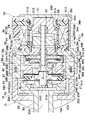
- FIG. 3 is an enlarged cross-sectional view showing the damping force adjusting valve and the solenoid in FIG. 1 taken out.
- FIG. 3 is an enlarged cross-sectional view showing the solenoid in FIG. 1 taken out.
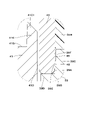
- It is an enlarged sectional view of the part (IV) in FIG.
- It is sectional drawing which shows the state which assembled the storage member (housing), the joining member (cylinder) and the yoke. It is sectional drawing of substantially the same position as FIG. 4 which shows a stator (anchor), a joining member, a yoke, etc. by 1st modification.
- the damping force adjusting type hydraulic shock absorber 1 (hereinafter referred to as hydraulic shock absorber 1) includes a damping force adjusting mechanism 17 having a solenoid 33 as a drive source. That is, the hydraulic shock absorber 1 as a damping force adjusting shock absorber includes an outer cylinder 2, an inner cylinder 4 as a cylinder, a piston 5, a piston rod 8, a rod guide 9, and a damping force adjusting mechanism 17. It is configured to include.
- the hydraulic shock absorber 1 is provided with a bottomed cylindrical outer cylinder 2 forming an outer shell.
- the lower end side of the outer cylinder 2 is closed by the bottom cap 3 using welding means or the like.
- the upper end side of the outer cylinder 2 is a crimped portion 2A bent inward in the radial direction.
- a rod guide 9 and a sealing member 10 are provided between the caulking portion 2A and the inner cylinder 4.
- an opening 2B is formed concentrically with the connection port 12C of the intermediate cylinder 12.
- a damping force adjusting mechanism 17 is attached to the lower side of the outer cylinder 2 so as to face the opening 2B.
- the bottom cap 3 is provided with a mounting eye 3A that is mounted on the wheel side of the vehicle, for example.
- the inner cylinder 4 is provided coaxially with the outer cylinder 2.
- the lower end side of the inner cylinder 4 is fitted and attached to the bottom valve 13.
- the upper end side of the inner cylinder 4 is fitted and attached to the rod guide 9.
- An oil liquid as a working fluid (working fluid) is sealed in the inner cylinder 4 as a cylinder.
- the hydraulic fluid is not limited to oil and oil, and may be, for example, water mixed with additives.
- An annular reservoir chamber A is formed between the inner cylinder 4 and the outer cylinder 2. Gas is sealed in the reservoir chamber A together with the oil liquid. This gas may be air in an atmospheric pressure state, or a gas such as compressed nitrogen gas may be used. The reservoir chamber A compensates for the entry and exit of the piston rod 8.
- An oil hole 4A that allows the rod-side oil chamber B to always communicate with the annular oil chamber D is bored in the radial direction at an intermediate position in the length direction (axial direction) of the inner cylinder 4.
- the piston 5 is slidably inserted into the inner cylinder 4. That is, the piston 5 is slidably provided in the inner cylinder 4.
- the piston 5 defines (partitions) the inside of the inner cylinder 4 into two chambers, a rod-side oil chamber B and a bottom-side oil chamber C.
- a plurality of oil passages 5A and 5B that allow the rod-side oil chamber B and the bottom-side oil chamber C to communicate with each other are formed in the piston 5 so as to be separated from each other in the circumferential direction.
- a disc valve 6 on the extension side is provided on the lower end surface of the piston 5.
- the disc valve 6 on the extension side opens when the pressure in the oil chamber B on the rod side exceeds the relief set pressure when the piston 5 slides and displaces upward in the extension stroke of the piston rod 8, and the pressure at this time. Is relieved to the bottom side oil chamber C side via each oil passage 5A.
- the relief set pressure is set to a pressure higher than the valve opening pressure when the damping force adjusting mechanism 17 is set hard.
- a contraction-side check valve 7 is provided on the upper end surface of the piston 5 to open the valve when the piston 5 slides and displaces downward in the contraction stroke of the piston rod 8, and closes the valve at other times.
- the check valve 7 allows the oil liquid in the bottom side oil chamber C to flow in each oil passage 5B toward the rod side oil chamber B, and prevents the oil liquid from flowing in the opposite direction. ..
- the valve opening pressure of the check valve 7 is set to a pressure lower than the valve opening pressure when the damping force adjusting mechanism 17 is softly set, and substantially no damping force is generated. The fact that this substantially no damping force is generated is a force equal to or less than the friction of the piston 5 and the seal member 10, and does not affect the motion of the vehicle.
- the piston rod 8 extends in the inner cylinder 4 in the axial direction (upper and lower directions in FIG. 1).
- the lower end side of the piston rod 8 is inserted into the inner cylinder 4.
- the piston rod 8 is provided so as to be fixed to the piston 5 by a nut 8A or the like.
- the upper end side of the piston rod 8 projects to the outside of the outer cylinder 2 and the inner cylinder 4 via the rod guide 9. That is, the piston rod 8 is connected to the piston 5 and extends to the outside of the inner cylinder 4.
- the lower end of the piston rod 8 may be further extended so as to project outward from the bottom portion (for example, the bottom cap 3) side to form so-called both rods.
- a stepped cylindrical rod guide 9 is provided on the upper end side of the inner cylinder 4.
- the rod guide 9 positions the upper portion of the inner cylinder 4 at the center of the outer cylinder 2 and guides the piston rod 8 so as to be slidable in the axial direction on the inner peripheral side thereof.
- An annular sealing member 10 is provided between the rod guide 9 and the crimped portion 2A of the outer cylinder 2.
- the seal member 10 is configured by, for example, baking an elastic material such as rubber on a metal annular plate provided with a hole through which the piston rod 8 is inserted in the center.
- the sealing member 10 seals between the elastic material and the piston rod 8 by the inner circumference of the elastic material sliding in contact with the outer peripheral side of the piston rod 8.
- the seal member 10 is formed with a lip seal 10A as a check valve extending so as to come into contact with the rod guide 9 on the lower surface side.
- the lip seal 10A is arranged between the oil reservoir 11 and the reservoir chamber A.
- the lip seal 10A allows the oil liquid or the like in the oil reservoir 11 to flow toward the reservoir chamber A side through the return passage 9A of the rod guide 9, and blocks the flow in the opposite direction.
- An intermediate cylinder 12 made of a cylinder is arranged between the outer cylinder 2 and the inner cylinder 4.
- the intermediate cylinder 12 is attached to, for example, on the outer peripheral side of the inner cylinder 4 via upper and lower tubular seals 12A and 12B.
- the intermediate cylinder 12 has an annular oil chamber D extending inside so as to surround the outer peripheral side of the inner cylinder 4 over the entire circumference.
- the annular oil chamber D is an oil chamber independent of the reservoir chamber A.
- the annular oil chamber D is always in communication with the rod side oil chamber B by the radial oil hole 4A formed in the inner cylinder 4.
- the annular oil chamber D is a flow path in which the working liquid flows due to the movement of the piston rod 8.
- a connection port 12C to which the connection pipe body 20 of the damping force adjusting valve 18 is attached is provided on the lower end side of the intermediate cylinder 12.
- the bottom valve 13 is located on the lower end side of the inner cylinder 4 and is provided between the bottom cap 3 and the inner cylinder 4.
- the bottom valve 13 has a valve body 14 that defines (partitions) the reservoir chamber A and the bottom side oil chamber C between the bottom cap 3 and the inner cylinder 4, and a reduction side provided on the lower surface side of the valve body 14.
- the disc valve 15 and the extension side check valve 16 provided on the upper surface side of the valve body 14 are configured.
- the valve body 14 is formed with oil passages 14A and 14B that allow the reservoir chamber A and the bottom side oil chamber C to communicate with each other at intervals in the circumferential direction.
- the disc valve 15 on the reduction side opens when the pressure in the oil chamber C on the bottom side exceeds the relief set pressure when the piston 5 slides and displaces downward in the reduction stroke of the piston rod 8, and the pressure at this time. Is relieved to the reservoir chamber A side via each oil passage 14A.
- the relief set pressure is set to a pressure higher than the valve opening pressure when the damping force adjusting mechanism 17 is set hard.
- the extension-side check valve 16 opens when the piston 5 slides and displaces upward in the extension stroke of the piston rod 8, and closes at other times.
- the check valve 16 allows the oil liquid in the reservoir chamber A to flow in each oil passage 14B toward the bottom side oil chamber C, and prevents the oil liquid from flowing in the opposite direction.
- the valve opening pressure of the check valve 16 is set to a pressure lower than the valve opening pressure when the damping force adjusting mechanism 17 is softly set, and substantially no damping force is generated.
- the damping force adjusting mechanism 17 controls the flow of the working liquid generated by the sliding of the piston 5 in the cylinder (inner cylinder 4) to generate a damping force, and variably adjusts the generated damping force of the hydraulic shock absorber 1. It is a mechanism.
- the amateur 48 actuating pin 49
- FIG. 2 shows a state in which the pilot valve body 32 has moved to the left side (that is, the valve closing direction in which the pilot valve body 32 is seated on the valve seat portion 26E of the pilot body 26).
- the damping force adjusting mechanism 17 is arranged so that its base end side (left end side in FIG. 1) is interposed between the reservoir chamber A and the annular oil chamber D, and the tip end side (FIG. 1). The right end side) is provided so as to project outward in the radial direction from the lower side of the outer cylinder 2.
- the damping force adjusting mechanism 17 generates a damping force by controlling the flow of the oil liquid from the annular oil chamber D to the reservoir chamber A by the damping force adjusting valve 18. Further, the generated damping force is variably adjusted by adjusting the valve opening pressure of the damping force adjusting valve 18 with the solenoid 33 used as the damping force variable actuator. In this way, the damping force adjusting mechanism 17 controls the flow of the working fluid (oil liquid) generated by the sliding of the piston 5 in the inner cylinder 4 to generate the damping force.
- the damping force adjusting mechanism 17 includes a damping force adjusting valve 18 that generates a damping force having hard or soft characteristics by variably controlling the flow of oil liquid from the annular oil chamber D to the reservoir chamber A, and a damping force adjusting valve. It is configured to include a solenoid 33 for adjusting the operation of the on-off valve of 18. That is, the valve opening pressure of the damping force adjusting valve 18 is adjusted by the solenoid 33 used as the damping force variable actuator, whereby the generated damping force is variably controlled to a hard or soft characteristic.
- the damping force adjusting valve 18 is a valve whose on-off valve operation is adjusted by a solenoid 33, and is a flow path (for example, between the annular oil chamber D and the reservoir chamber A) where the flow of the working liquid is generated by the movement of the piston rod 8. It is provided in.
- the damping force adjusting valve 18 has a substantially cylindrical valve case 19 provided so that the base end side thereof is fixed around the opening 2B of the outer cylinder 2 and the tip end side protrudes radially outward from the outer cylinder 2.
- the connection tube 20 is fixed to the connection port 12C of the intermediate cylinder 12 on the base end side, and the tip side is an annular flange portion 20A, which is arranged inside the valve case 19 with a gap, and the connection tube body 20. It is configured to include a valve member 21 that abuts on the flange portion 20A.
- the base end side of the valve case 19 is an annular inner flange portion 19A extending inward in the radial direction.
- the tip end side of the valve case 19 is a male screw portion 19B into which a lock nut 53 for connecting the valve case 19 and the yoke 39 (one-side cylinder portion 39G) of the solenoid 33 is screwed.
- An annular oil that always communicates with the reservoir chamber A between the inner peripheral surface of the valve case 19 and the outer peripheral surface of the valve member 21, and further between the inner peripheral surface of the valve case 19 and the outer peripheral surface of the pilot body 26 or the like. Room 19C.
- the valve case 19 and the solenoid 33 are connected by a locknut 53, or may be configured such that the tip end side of the valve case is crimped to the yoke of the solenoid (a configuration that does not use a locknut).
- an oil passage 20B that communicates with the annular oil chamber D and the other side extends to the position of the valve member 21.
- an annular spacer 22 is provided in a sandwiched state between the flange portion 20A of the connecting pipe body 20 and the inner flange portion 19A of the valve case 19.
- the spacer 22 is provided with a plurality of notches 22A that serve as radial oil passages so as to communicate with the oil chamber 19C and the reservoir chamber A so as to extend radially.
- the spacer 22 is provided with a notch 22A for forming an oil passage.
- notches for forming an oil passage may be provided radially in the inner flange portion 19A of the valve case 19. With this configuration, the spacer 22 can be omitted and the number of parts can be reduced.
- the valve member 21 is provided with a central hole 21A located at the center in the radial direction and extending in the axial direction. Further, the valve member 21 is provided with a plurality of oil passages 21B around the central hole 21A so as to be spaced apart from each other in the circumferential direction. One side of each oil passage 21B (left side of FIGS. 1 and 2) is always in communication with the oil passage 20B side of the connecting pipe body 20. Further, on the end surface of the other side (right side of FIGS. 1 and 2) of the valve member 21, an annular recess 21C formed so as to surround the other side opening of the oil passage 21B and a radial outer side of the annular recess 21C.
- each oil passage 21B of the valve member 21 is a main valve between the oil passage 20B of the connecting pipe body 20 communicating with the annular oil chamber D and the oil chamber 19C of the valve case 19 communicating with the reservoir chamber A. It becomes a flow path through which the pressure oil of the flow rate corresponding to the opening degree of 23 flows.
- the main valve 23 is composed of a disc valve whose inner peripheral side is sandwiched between the valve member 21 and the large diameter portion 24A of the pilot pin 24.
- the outer peripheral side of the main valve 23 is taken off and seated on the annular valve seat 21D of the valve member 21.
- An elastic seal member 23A is fixed to the outer peripheral portion on the back surface side of the main valve 23 by means such as baking.
- the main valve 23 is opened by receiving the pressure on the oil passage 21B side (annular oil chamber D side) of the valve member 21 and separating from the annular valve seat 21D.
- the oil passage 21B (annular oil chamber D side) of the valve member 21 is communicated with the oil chamber 19C (reservoir chamber A side) via the main valve 23, and the amount of pressure oil flowing in the arrow Y direction at this time. (Flow rate) is variably adjusted according to the opening degree of the main valve 23.
- the pilot pin 24 is formed in a stepped cylindrical shape, and an annular large diameter portion 24A is provided in the intermediate portion in the axial direction.
- the pilot pin 24 has a central hole 24B extending in the axial direction on the inner peripheral side.
- a small diameter hole (orifice 24C) is formed at one end of the central hole 24B (the end on the connecting tube body 20 side).
- One end side (left end side of FIGS. 1 and 2) of the pilot pin 24 is press-fitted into the center hole 21A of the valve member 21, and the main valve 23 is sandwiched between the large diameter portion 24A and the valve member 21.
- the other end side of the pilot pin 24 (the right end side of FIGS. 1 and 2) is fitted in the center hole 26C of the pilot body 26.
- an oil passage 25 extending in the axial direction is formed between the center hole 26C of the pilot body 26 and the other end side of the pilot pin 24.
- the oil passage 25 communicates with a back pressure chamber 27 formed between the main valve 23 and the pilot body 26.
- a plurality of oil passages 25 extending in the axial direction are provided on the side surface on the other end side of the pilot pin 24 in the circumferential direction, and the other peripheral positions are press-fitted into the central hole 26C of the pilot body 26.
- the pilot body 26 is formed as a substantially bottomed tubular body, and has a cylindrical portion 26A having a stepped hole formed inside and a bottom portion 26B that closes the cylindrical portion 26A.
- the bottom portion 26B of the pilot body 26 is provided with a center hole 26C into which the other end side of the pilot pin 24 is fitted.
- a protruding cylinder portion 26D located on the outer diameter side and protruding toward the valve member 21 over the entire circumference is integrally provided. ..
- the elastic sealing member 23A of the main valve 23 is liquid-tightly fitted to the inner peripheral surface of the protruding cylinder portion 26D, thereby forming a back pressure chamber 27 between the main valve 23 and the pilot body 26. ing.
- the back pressure chamber 27 generates a pressure (internal pressure, pilot pressure) that presses the main valve 23 in the valve closing direction, that is, in the direction in which the main valve 23 is seated on the annular valve seat 21D of the valve member 21.
- a valve seat portion 26E on which the pilot valve body 32 takes off and sits is provided so as to surround the central hole 26C. Further, inside the cylindrical portion 26A of the pilot body 26, when the return spring 28 for urging the pilot valve body 32 in the direction away from the valve seat portion 26E of the pilot body 26 and the solenoid 33 are in a non-energized state (pilot valve body).
- a disc valve 29 constituting a fail-safe valve (when 32 is farthest from the valve seat portion 26E), a holding plate 30 having an oil passage 30A formed on the center side, and the like are arranged.
- a cap 31 is fitted and fixed to the open end of the cylindrical portion 26A of the pilot body 26 with a return spring 28, a disc valve 29, a holding plate 30, and the like arranged inside the cylindrical portion 26A.
- the cap 31 is formed with notches 31A at four positions separated from each other in the circumferential direction, for example. As shown by the arrow X in FIG. 2, the notch 31A is a flow path for flowing the oil liquid flowing to the solenoid 33 side through the oil passage 30A of the holding plate 30 to the oil chamber 19C (reservoir chamber A side). ..
- the pilot valve body 32 constitutes a pilot valve (control valve) together with the pilot body 26.
- the pilot valve body 32 is formed in a stepped cylindrical shape.
- the tip of the pilot valve body 32 that is, the tip of the pilot body 26 that takes off and sits on the valve seat portion 26E, has a tapered shape.
- An actuating pin 49 of the solenoid 33 is fitted and fixed inside the pilot valve body 32, and the valve opening pressure of the pilot valve body 32 is adjusted according to the energization of the solenoid 33.
- the pilot valve (pilot body 26 and pilot valve body 32) as a control valve is controlled by the movement of the actuating pin 49 (that is, the amateur 48) of the solenoid 33.
- a flange portion 32A serving as a spring receiver is formed on the proximal end side of the pilot valve body 32 over the entire circumference.
- the flange portion 32A comes into contact with the inner peripheral portion of the disc valve 29 when the solenoid 33 is in a non-energized state, that is, when the pilot valve body 32 is displaced to the fully open position farthest from the valve seat portion 26E. It constitutes a fail-safe valve.
- FIGS. 3 to 5 the reference numerals are given with the right side of FIG. 2 facing upward. That is, the left and right directions of FIGS. 1 and 2 correspond to the upper and lower directions of FIGS. 3 to 5.
- the solenoid 33 is incorporated in the damping force adjusting mechanism 17 as a damping force variable actuator of the damping force adjusting mechanism 17. That is, the solenoid 33 is used in the damping force adjusting type shock absorber to adjust the operation of the on-off valve of the damping force adjusting valve 18.
- the solenoid 33 includes a mold coil 34, a housing 36 as a storage member, a yoke 39, an anchor 41 as a stator, a cylinder 44 as a joining member (non-magnetic ring), and a mover (movable iron core). It includes an amateur 48, an actuating pin 49, and a cover member 51.
- the inner diameter of the coil can be suppressed from becoming large and the outer diameter of the amateur can be made large.
- the housing (core 74) and the yoke (solenoid case 71) are connected via a joining member (unsigned).
- the inner diameter side (inner circumference) of one end of the joining member (unsigned) is fixed to the outer diameter side (outer circumference) of the yoke (solenoid case 71), and the outer diameter side (outer circumference) of the housing (core 74) is fixed.
- the inner diameter side (inner circumference) of the other end of the joining member is fixed.
- the joining member (unsigned) is placed on the outer diameter side of the yoke (solenoid case 71). It is considered that the inner diameter side of one end is fixed by press fitting, and the inner diameter side of the other end of the joining member is fixed by press fitting to the outer diameter side of the housing (core 74), and each is joined by brazing. ..
- the portion of the joining member that fits with the yoke is a large-diameter portion (overhanging portion) having a larger radial dimension (inner diameter dimension) than the other portion, and a stator is formed in this large-diameter portion.
- the thickness of the stator and the joining member can be secured by adopting a configuration in which the yoke and the yoke are inserted.
- the material cost and the processing cost may increase due to the complicated shape of the joining member.
- the position of the coil may move to the housing side and the shaft length may increase. For these reasons, in the case of the prior art, it is difficult to improve the thrust characteristics of the solenoid and shorten the shaft length.
- the shape of the cylinder 44 is cylindrical.
- the inner circumference (inner diameter side) and the outer circumference (outer diameter side) of the housing 36 (small diameter cylinder portion 36C) are fixed (assembled) by press fitting, and then brazed and joined.
- the cylinder 44 is made of, for example, stainless steel
- the housing 36 and the yoke 39 are made of, for example, carbon steel for machine structure (S10C).
- the cylinder 44 and the housing 36 are heated (temperature rise) due to brazing, the cylinder 44 tends to swell more than the housing 36 (small diameter cylinder portion 36C) due to the difference in material properties.
- the brazing material for example, a copper ring enters the inner circumference of the cylinder 44 and the outer circumference of the housing 36 (small diameter cylinder portion 36C).
- the solenoid 33 includes a mold coil 34, a housing 36, a yoke 39, an anchor 41, a cylinder 44, an amateur 48, and an actuating pin 49.
- the mold coil 34 is formed in a substantially cylindrical shape by integrally covering (molding) the coil 34A with a resin member 34C such as a thermosetting resin in a state where the coil 34A is wound around the coil bobbin 34B. ..
- a cable take-out portion 34E protruding outward in the axial direction or the radial direction is provided in a part of the circumferential direction of the mold coil 34, and an electric wire cable (not shown) is connected to the cable take-out portion 34E.
- the coil 34A of the mold coil 34 is wound in an annular shape around the coil bobbin 34B, and becomes an electromagnet to generate a magnetic force by supplying electric power (energization) through a cable from the outside.
- a seal groove 34D is formed over the entire circumference on the side surface (end surface on one side in the axial direction) facing the yoke 39 (annular portion 39B).
- a seal member for example, an O-ring 35
- the O-ring 35 tightly seals between the mold coil 34 and the yoke 39 (annular portion 39B). This makes it possible to prevent dust including rainwater and muddy water from entering the tubular protrusion 39C side of the yoke 39 via between the yoke 39 and the mold coil 34.
- the coil used in this embodiment is not limited to the molded coil 34 composed of the coil 34A, the coil bobbin 34B, and the resin member 34C, and other coils may be used.
- the outer periphery of the coil may be covered with an overmold (not shown) obtained by molding a resin material from above (outer peripheral side).
- the housing 36 constitutes a first fixed iron core (storage member) arranged and provided on the inner peripheral side of the mold coil 34 (that is, the inner circumference of the coil 34A).
- the housing 36 is formed as a covered cylindrical cylinder by a magnetic material (magnetic material) such as low carbon steel or carbon steel for machine structure (S10C).
- the housing 36 has a storage cylinder portion 36A as a storage portion that extends in the winding axis direction of the mold coil 34 (coil 34A) and has one end side (left side in FIG. 2, lower side in FIGS. 3 to 5) open.
- the outer circumference of the storage cylinder portion 36A is covered by a stepped lid portion 36B that closes the other end side (right side of FIG. 2, upper side of FIGS. 3 to 5) and an opening side (one side) of the storage cylinder portion 36A. It is configured to include a small diameter cylinder portion 36C for joining formed so as to reduce the diameter.
- the inner circumference of the cylinder 44 is joined to the outer circumference of the small diameter cylinder portion 36C of the housing 36 by brazing.
- the inner diameter of the storage cylinder portion 36A of the housing 36 is formed to be slightly larger than the outer diameter of the amateur 48, and the amateur 48 is housed in the storage cylinder portion 36A so as to be movable in the axial direction.
- the lid portion 36B of the housing 36 is integrally formed with the storage cylinder portion 36A as a covered cylinder that closes the storage cylinder portion 36A from the other side in the axial direction.
- the outer diameter of the lid portion 36B has a stepped shape smaller than the outer diameter of the storage cylinder portion 36A, and the fitting cylinder portion 51A of the cover member 51 is fitted and provided on the outer peripheral side of the lid portion 36B.
- the housing 36 is formed with a bottomed stepped hole 37 located inside the lid portion 36B.
- the stepped hole 37 includes a bush mounting hole portion 37A and a small diameter hole portion 37B located on the back side of the bush mounting hole portion 37A and formed to have a small diameter.
- a first bush 38 for slidably supporting the actuating pin 49 is provided in the bush mounting hole 37A.
- the lid portion 36B of the housing 36 is arranged so that the other side end faces face the lid plate 51B of the cover member 51 with a gap in the axial direction.
- This axial gap has a function of preventing an axial force from being directly applied to the housing 36 from the lid plate 51B side of the cover member 51 via the lid portion 36B.
- the lid portion 36B of the housing 36 does not necessarily have to be integrally formed of the same material (magnetic material) as the storage cylinder portion 36A.
- the lid portion 36B can be formed of, for example, a rigid metal material, a ceramic material, or a fiber-reinforced resin material instead of the magnetic material.
- the joint between the storage cylinder portion 36A and the lid portion 36B of the housing 36 is set at a position in consideration of the transfer of magnetic flux.
- the yoke 39 is a magnetic member that forms a magnetic circuit (magnetic path) over the inner peripheral side and the outer peripheral side of the molded coil 34 (coil 34A) together with the housing 36.
- the yoke 39 is formed by using a magnetic material (magnetic material) like the housing 36, extends radially on one side in the axial direction (one side in the winding axis direction) of the mold coil 34 (coil 34A), and the yoke 39 thereof extends in the radial direction.
- the tubular protrusion 39C constitutes a protrusion (cylinder portion) for joining with the cylinder 44, and the cylinder 44 is inserted on the inner diameter side of the tubular protrusion 39C.
- the yoke 39 has a fixing hole 39A, and the inner peripheral surface of the fixing hole 39A faces a part of the side surface portion 41D of the anchor 41. Further, in the fixing hole 39A, an inward flange portion 39D protruding toward the inner diameter side is provided over the entire circumference. An end surface (one end surface) on one side in the axial direction of the cylinder 44 is in contact with the side surface (side surface on the coil 34A side) of the inward flange portion 39D.
- the outer periphery of the cylinder 44 on one axial direction is fitted to the inner circumference of the yoke 39, that is, the inner surface of the fixing hole 39A (in other words, the inner peripheral surface of the tubular protrusion 39C).
- the fixing hole 39A (inner diameter side of the tubular protrusion 39C) of the yoke 39 is formed with a small diameter hole portion 39E having a smaller inner diameter in order from one side in the axial direction (inward flange 39D side). It is provided with a large-diameter hole portion 39F having an inner diameter larger than that of the small-diameter hole portion 39E.
- the cylinder 44 and the yoke 39 are on the housing 36 side in the winding axis direction of the coil 34A, that is, on the other side in the axial direction, the outer circumference of the cylinder 44 and the inner circumference of the yoke 39 (inner surface of the fixing hole 39A, cylindrical shape).
- a non-contact portion 45 that is non-contact with the protrusion (inner peripheral surface of the protrusion 39C) is formed. Further, the cylinder 44 and the yoke 39 are on the side opposite to the housing 36 side in the winding axis direction of the coil 34A, that is, on one side in the axial direction, the outer circumference of the cylinder 44 and the inner circumference of the yoke 39 (inner surface of the fixing hole 39A). , The inner peripheral surface of the tubular protrusion 39C) is press-fitted to form a press-fitting portion 46.
- the non-contact portion 45 is set so as to secure a gap for the brazing material to enter when the temperature of the cylinder 44 and the yoke 39 rises due to brazing, for example.
- the yoke 39 has a cylindrical one-sided tubular portion 39G extending from the outer peripheral side of the annular portion 39B toward one side in the axial direction (damping force adjusting valve 18 side) and the other side in the axial direction from the outer peripheral side of the annular portion 39B.
- the other side cylinder portion 39H extending toward (cover member 51 side) and surrounding the mold coil 34 from the radial outside, and the flange portion of the cover member 51 provided on the tip end side of the other side cylinder portion 39H. It is formed as an integral body including a caulking portion 39J that holds 51C in a retaining state.
- the other side cylinder portion 39H of the yoke 39 is provided with a notch 39K for exposing the cable extraction portion 34E of the mold coil 34 to the outside of the other side cylinder portion 39H.
- an engagement recess 39L having a semicircular cross section so as to open on the outer peripheral surface of the yoke 39 is provided (over the entire circumference or in the circumferential direction). It is provided in multiple places) apart from each other.
- a lock nut 53 screwed to the valve case 19 of the damping force adjusting valve 18 is engaged with the engaging recess 39L via a retaining ring 54 (see FIG. 2).
- a seal groove 39M is provided on the outer peripheral surface of the one-side cylinder portion 39G over the entire circumference.
- An O-ring 40 (see FIG. 2) as a sealing member is mounted on the sealing groove 39M. The O-ring 40 tightly seals between the yoke 39 (one-side cylinder portion 39G) and the valve case 19 of the damping force adjusting valve 18.
- the anchor 41 is a second fixed iron core (stator) fixed in the fixing hole 39A of the yoke 39 by means such as press fitting.
- the anchor 41 fills the fixing hole 39A of the yoke 39 from the inside with a magnetic material (magnetic material) such as low carbon steel and carbon steel for machine structure (S10C) like the housing 36 (first fixed iron core) and the yoke 39. It is formed in a shape.
- the anchor 41 is formed as a short cylindrical annular body having a through hole 41A whose central side extends in the axial direction.
- One side surface of the anchor 41 in the axial direction (the surface facing the cap 31 of the damping force adjusting valve 18 shown in FIG. 2 in the axial direction) is formed so as to be a flat surface like one side surface of the annular portion 39B of the yoke 39. ing.
- a circular concave recess 41B is recessed on the other side of the anchor 41 in the axial direction (the other side surface facing the amateur 48 in the axial direction) so as to be coaxial with the storage cylinder portion 36A.
- the recessed portion 41B is formed as a circular groove having a diameter slightly larger than that of the amateur 48 so that the amateur 48 can be inserted into and out of the recessed portion 41B by a magnetic force.
- a cylindrical protrusion 41C is provided on the other side of the anchor 41.
- the outer peripheral surface of the protrusion 41C on the opening side is formed as a conical surface so that the magnetic characteristic is linear between the anchor 41 and the amateur 48.
- the protruding portion 41C which is also called a corner portion, protrudes in a cylindrical shape from the outer peripheral side of the anchor 41 toward the other side in the axial direction.
- the outer peripheral surface (outer peripheral surface on the opening side) of the protrusion 41C is a conical surface inclined in a tapered shape so that the outer diameter dimension gradually decreases toward the other side (opening side) in the axial direction. ..
- the protruding portion 41C of the anchor 41 is provided at a position facing the opening of the housing 36 (storage cylinder portion 36A), and the reduced diameter portion 41C1 whose outer diameter is reduced as it approaches the opening of the storage cylinder portion 36A. Have.
- a side surface portion 41D extending in a direction away from the opening of the storage cylinder portion 36A of the housing 36 is formed along the outer peripheral side of the protruding portion 41C.
- the end portion of the side surface portion 41D on the side away from the opening is an annular flange portion 41E protruding outward in the radial direction.
- the annular flange portion 41E is arranged at a position largely separated from the opening end of the storage cylinder portion 36A of the housing 36 on one side in the axial direction (that is, the end portion on the side opposite to the recessed portion 41B).
- the annular flange portion 41E is fixed in the fixing hole 39A of the yoke 39 by means such as press fitting.
- the annular flange portion 41E is a fixing portion of the anchor 41 (side surface portion 41D) with respect to the fixing hole 39A of the yoke 39, and is also a portion where the flange portion 41E and the fixing hole 39A face each other in the radial direction.
- the side surface portion 41D (excluding the annular flange portion 41E) of the anchor 41 faces the inner peripheral surface of the cylinder 44 and the inner surface of the inward flange portion 39D of the yoke 39 via a gap (diameter gap).
- the protruding portion 41C and the side surface portion 41D are integrally formed by a magnetic material.
- the anchor 41 is provided at a position facing the opening of the storage cylinder portion 36A of the housing 36.
- the protruding portion 41C projects toward the opening of the storage cylinder portion 36A of the housing 36.
- the side surface portion 41D extends from the outer periphery of the protruding portion 41C in a direction away from the opening of the storage cylinder portion 36A of the housing 36.
- the side surface portion 41D has a gap with respect to the inner peripheral surface of the cylinder 44 and the inner surface of the inward flange portion 39D of the yoke 39.
- a second bush 43 for slidably supporting the actuating pin 49 is fitted in the stepped through hole 41A formed on the center (inner circumference) side of the anchor 41. It is provided.
- a pilot body 26 of the damping force adjusting valve 18, a return spring 28, a disc valve 29, a holding plate 30, a cap 31, and the like are provided on the inner peripheral side of the one-side cylinder portion 39G of the yoke 39. It is provided by inserting it. Further, the valve case 19 of the damping force adjusting valve 18 is fitted (outerly fitted) on the outer peripheral side of the one-side cylinder portion 39G.
- the cylinder 44 is provided between the yoke 39 and the anchor 41 in the radial direction. Further, the cylinder 44 is provided between the yoke 39 and the housing 36 in the axial direction and the radial direction. That is, the cylinder 44 is a non-magnetic connecting member (cylinder 34A) located on the inner peripheral side of the mold coil 34 (coil 34A) located between the small diameter tubular portion 36C of the housing 36 and the tubular protrusion 39C of the yoke 39. Joining member).
- the cylinder 44 is made of a non-magnetic material. More specifically, the cylinder 44 is formed as a cylinder (simple cylinder) by a non-magnetic material such as austenitic stainless steel.
- the outer circumference of the mold coil 34 (coil 34A) on one end side (yoke 39 side) in the winding axis direction is joined to the inner circumference of the yoke 39 (fixing hole 39A, tubular protrusion 39C).
- the inner circumference of the other end side (housing 36 side) of the mold coil 34 (coil 34A) in the winding axis direction is joined to the outer circumference of the housing 36 (small diameter cylinder portion 36C). That is, the cylinder 44 is fitted (press-fitted) to the outside (outer peripheral side) of the small-diameter cylinder portion 36C of the housing 36, and both are joined by brazing.
- the cylinder 44 is fitted (press-fitted) to the inside (inner peripheral side) of the tubular protrusion 39C of the yoke 39, and both are joined by brazing.
- the cylinder 44 and the housing 36 are press-fitted
- the cylinder 44 and the yoke 39 are press-fitted
- the cylinder 44, the housing 36, and the yoke 39 are assembled, and then brazing joint is performed.
- the housing 36 and the cylinder 44, and the cylinder 44 and the yoke 39 are joined via a brazing material.
- the brazing filler metal for example, pure copper brazing filler metal can be used. That is, the brazing can be performed by, for example, a brazing treatment at 1000 ° C. or higher using a brazing material (copper ring) made of pure copper brazing.
- the brazing material may be other than pure copper brazing. For example, brass brazing, nickel brazing, gold brazing, palladium brazing and the like may be used.
- the cylinder 44 is joined to the small-diameter cylinder portion 36C of the housing 36 and the tubular protrusion portion 39C of the yoke 39 by brazing. After the brazing process, a quenching process is performed. In this state, the inner diameter of the cylinder 44 is formed to be larger than the outer diameter of the side surface portion 41D of the anchor 41.
- the cylinder 44, the yoke 39, and the housing 36 are made of materials having different coefficients of linear expansion.
- the cylinder 44 is made of stainless steel and the housing 36 is made of carbon steel for machine structure (S10C).
- S10C machine structure
- the stainless steel cylinder 44 having a large coefficient of linear expansion expands more than the housing 36, and the inner circumference of the other end side of the cylinder 44
- the brazing material can be stored in the gap formed between the housing 36 (small diameter cylinder portion 36C) and the outer periphery thereof. Thereby, the sealing property between the cylinder 44 and the housing 36 (small diameter cylinder portion 36C) can be improved.
- the fixing hole 39A of the yoke 39 includes a large-diameter hole 39F having a larger inner diameter than the small-diameter hole 39E.
- the non-contact portion 45 is provided between the cylinder 44 and the yoke 39, that is, between the outer circumference of the cylinder 44 and the inner circumference of the yoke 39 (inner surface of the fixing hole 39A, inner peripheral surface of the tubular protrusion 39C). Is forming.
- the outer circumference of the cylinder 44 and the outer circumference of the cylinder 44 can be stored in the non-contact portion 45 between the inner circumference of the yoke 39 (the inner surface of the fixing hole 39A and the inner peripheral surface of the tubular protrusion 39C). Thereby, the sealing property between the cylinder 44 and the yoke 39 (fixing hole 39A) can be improved.
- the joining between the cylinder 44 and the housing 36 and / or the joining between the cylinder 44 and the yoke 39 is performed by heating with a joining means other than brazing (for example, a joining means by welding such as laser welding). It may be a configuration. That is, the housing 36 and the cylinder 44, and the cylinder 44 and the yoke 39 may be joined by welding.
- the amateur 48 is a mover made of a magnetic material provided between the storage cylinder portion 36A of the housing 36 and the recessed portion 41B of the anchor 41 so as to be movable in the winding axis direction of the coil 34A.
- the amateur 48 is arranged on the storage cylinder portion 36A of the housing 36, the recessed portion 41B of the anchor 41, the tubular protrusion 39C of the yoke 39, and the inner peripheral side of the cylinder 44, and the storage cylinder portion 36A and the anchor 41 of the housing 36 are arranged. It is movable in the axial direction from the recessed portion 41B.
- the amateur 48 is arranged on the inner peripheral side of the storage cylinder portion 36A of the housing 36 and the recessed portion 41B of the anchor 41, and the first and second bushes 38 and 43 and the actuating pin 49 are pressed by the magnetic force generated in the coil 34A. It is possible to move in the axial direction via.
- the amateur 48 is fixed (integrated) to the actuating pin 49 extending through the center side thereof, and moves together with the actuating pin 49.
- the actuating pin 49 is slidably supported in the lid portion 36B of the housing 36 and the anchor 41 via the first and second bushes 38 and 43.
- the amateur 48 is formed in a substantially cylindrical shape using an iron-based magnetic material, like the housing 36, the yoke 39, and the anchor 41, for example. Then, the amateur 48 generates a thrust in the direction of being attracted toward the recessed portion 41B of the anchor 41 by the magnetic force generated in the coil 34A.
- the actuating pin 49 is a shaft portion that transmits the thrust of the amateur 48 to the pilot valve body 32 of the damping force adjusting valve 18 (control valve), and is formed by a hollow rod.
- An amateur 48 is integrally fixed to an axially intermediate portion of the actuating pin 49 by means such as press fitting, whereby the amateur 48 and the actuating pin 49 are subassembled.
- Both sides of the actuating pin 49 in the axial direction are slidably supported by the lid portion 36B on the housing 36 side and the yoke 39 (anchor 41) via the first and second bushes 38 and 43.
- the actuating pin 49 protrudes axially from the anchor 41 (yoke 39), and the damping force adjusting valve is provided at the protruding end.
- the pilot valve body 32 of 18 is fixed. Therefore, the pilot valve body 32 moves integrally in the axial direction together with the amateur 48 and the actuating pin 49.
- the valve opening set pressure of the pilot valve body 32 is a pressure value corresponding to the thrust of the amateur 48 based on the energization of the coil 34A.
- the amateur 48 moves in the axial direction by the magnetic force from the coil 34A to open and close the pilot valve of the hydraulic shock absorber 1 (that is, the pilot valve body 32 with respect to the pilot body 26).
- the cover member 51 is a magnetic material cover that covers the mold coil 34 from the outside together with the other side cylinder portion 39H of the yoke 39.
- the cover member 51 is formed of a magnetic material (magnetic material) as a lid that covers the mold coil 34 from the other side in the axial direction, and is a magnetic circuit outside the mold coil 34 (coil 34A) together with the other side cylinder portion 39H of the yoke 39.
- the cover member 51 is formed in the shape of a covered cylinder as a whole, and has a cylindrical fitting cylinder portion 51A and the other end side of the fitting cylinder portion 51A (the right end portion in FIG. 2, the upper end portion in FIG. 3). ) Is roughly configured by a dish-shaped lid plate 51B that closes the lid plate 51B.
- the fitting cylinder portion 51A of the cover member 51 is inserted into the outer periphery of the lid portion 36B of the housing 36, and in this state, the lid portion 36B of the housing 36 is accommodated inside.
- the outer peripheral side of the lid plate 51B of the cover member 51 is an annular flange portion 51C whose outer peripheral side extends radially outward of the fitting cylinder portion 51A, and the outer peripheral edge of the flange portion 51C is on the other side cylinder portion 39H of the yoke 39. It is fixed to the provided caulking portion 39J.
- the other side cylinder portion 39H of the yoke 39 and the lid plate 51B of the cover member 51 are pre-assembled (sub-assembled) with the mold coil 34 built inside as shown in FIG.
- the lid portion 36B of the housing 36 is inside the fitting cylinder portion 51A of the cover member 51. It is fitted in. As a result, the magnetic flux can be transferred between the fitting cylinder portion 51A of the cover member 51, the lid plate 51B, and the yoke 39. Further, in the fitting cylinder portion 51A of the cover member 51, a seal groove 51D is formed over the entire circumference on the outer peripheral side where the resin member 34C of the mold coil 34 is fitted. A seal member (for example, an O-ring 52) is mounted in the seal groove 51D.
- a seal member for example, an O-ring 52
- the O-ring 52 tightly seals between the mold coil 34 and the cover member 51 (fitting cylinder portion 51A). As a result, dust including rainwater and muddy water invades between the housing 36 and the mold coil 34 via between the cover member 51 and the mold coil 34, and further between the housing 36 and the cover member 51 and the like. Can be prevented.
- the yoke 39 and the cover member 51 have a built-in mold coil 34 inside, and as shown in FIG. 2, a damping force is applied by using a lock nut 53 as a fastening member and a retaining ring 54. It is fastened to the valve case 19 of the adjustment valve 18.
- the retaining ring 54 is attached to the engaging recess 39L of the yoke 39 prior to the lock nut 53.
- the retaining ring 54 partially protrudes radially outward from the engaging recess 39L of the yoke 39, and transmits the fastening force of the lock nut 53 to the one-side cylinder portion 39G of the yoke 39.
- the locknut 53 is formed as a stepped tubular body, and has a female threaded portion 53A that is located on one side in the axial direction and is screwed into the male threaded portion 19B of the valve case 19 on the inner peripheral side thereof, and a retaining ring 54 having an inner diameter.
- An engaging cylinder portion 53B that is bent inward in the radial direction so as to be smaller than the outer diameter dimension and engages with the retaining ring 54 from the outside is provided.
- the locknut 53 has a female threaded portion 53A and a male threaded portion 19B of the valve case 19 in a state where the inner side surface of the engaging tube portion 53B is in contact with the retaining ring 54 mounted on the engaging recess 39L of the yoke 39. It is a fastening member that integrally connects the damping force adjusting valve 18 and the solenoid 33 by screwing and.
- the solenoid 33, the damping force adjusting mechanism 17, and the hydraulic shock absorber 1 according to the present embodiment have the above-mentioned configurations, and the operation thereof will be described next.
- the hydraulic shock absorber 1 when the hydraulic shock absorber 1 is mounted on a vehicle such as an automobile, for example, the upper end side (protruding end side) of the piston rod 8 is attached to the vehicle body side, and the attachment eye 3A side provided on the bottom cap 3 is a wheel. It is mounted on the side. Further, the solenoid 33 of the damping force adjusting mechanism 17 is connected to a control device (controller) provided on the vehicle body side of the vehicle via an electric wiring cable (neither is shown) or the like.
- a control device controller
- the piston rod 8 When the vehicle travels, when vibrations in the upward and downward directions occur due to unevenness of the road surface or the like, the piston rod 8 is displaced so as to extend or contract from the outer cylinder 2, and a damping force is generated by the damping force adjusting mechanism 17 or the like. And can dampen the vibration of the vehicle.
- the generated damping force of the hydraulic shock absorber 1 can be variably adjusted by controlling the current value of the solenoid 33 to the coil 34A by the controller and adjusting the valve opening pressure of the pilot valve body 32.
- the check valve 7 on the contraction side of the piston 5 closes due to the movement of the piston 5 in the inner cylinder 4.
- the oil liquid in the oil chamber B on the rod side is pressurized, and the damping force is adjusted through the oil hole 4A of the inner cylinder 4, the annular oil chamber D, and the connection port 12C of the intermediate cylinder 12. It flows into the oil passage 20B of the connecting pipe 20 of the valve 18.
- the oil liquid corresponding to the movement of the piston 5 flows from the reservoir chamber A into the bottom side oil chamber C by opening the extension side check valve 16 of the bottom valve 13.
- the pressure of the rod side oil chamber B reaches the valve opening pressure of the disc valve 6, the disc valve 6 opens and the pressure of the rod side oil chamber B is relieved to the bottom side oil chamber C.
- the oil liquid flowing into the oil passage 20B of the connecting pipe body 20 is a valve member as shown by an arrow X in FIG. 2 before the valve opening of the main valve 23 (piston speed low speed range). It passes through the central hole 21A of 21; the central hole 24B of the pilot pin 24, and the central hole 26C of the pilot body 26, pushes open the pilot valve body 32, and flows into the inside of the pilot body 26.
- the oil liquid that has flowed into the inside of the pilot body 26 is between the flange portion 32A of the pilot valve body 32 and the disc valve 29, the oil passage 30A of the holding plate 30, the notch 31A of the cap 31, and the oil of the valve case 19. It flows through the chamber 19C to the reservoir chamber A.
- the oil passage 20B of the connecting pipe body 20 When the pressure of the oil passage 20B of the connecting pipe body 20, that is, the pressure of the oil chamber B on the rod side reaches the valve opening pressure of the main valve 23 as the piston speed increases, the oil passage 20B of the connecting pipe body 20 is reached. As shown by the arrow Y in FIG. 2, the inflowing oil liquid passes through the oil passage 21B of the valve member 21, pushes open the main valve 23, passes through the oil chamber 19C of the valve case 19, and flows to the reservoir chamber A.
- the contraction side check valve 7 of the piston 5 opens due to the movement of the piston 5 in the inner cylinder 4, and the extension side check valve 16 of the bottom valve 13 closes.
- the oil liquid in the bottom side oil chamber C flows into the rod side oil chamber B.
- the oil liquid corresponding to the amount of the piston rod 8 infiltrated into the inner cylinder 4 flows from the rod side oil chamber B to the reservoir chamber A via the damping force adjusting valve 18 in the same route as during the extension stroke. ..
- the bottom valve 13 opens and the pressure in the bottom side oil chamber C is transferred to the reservoir chamber A. Relieve.
- the damping force is generated by the orifice 24C of the pilot pin 24 and the valve opening pressure of the pilot valve body 32 before the opening of the main valve 23 of the damping force adjusting valve 18.
- a damping force is generated according to the opening degree of the main valve 23.
- the damping force can be directly controlled regardless of the piston speed by adjusting the valve opening pressure of the pilot valve body 32 by energizing the coil 34A of the solenoid 33.
- the valve opening pressure of the pilot valve body 32 is reduced, and a damping force on the soft side is generated.
- the valve opening pressure of the pilot valve body 32 increases, and a damping force on the hard side is generated.
- the internal pressure of the back pressure chamber 27 communicating with the pilot valve body 32 via the oil passage 25 on the upstream side changes depending on the valve opening pressure of the pilot valve body 32.
- the pilot valve body 32 retracts (displaces in the direction away from the valve seat portion 26E) by the return spring 28, and the flange portion of the pilot valve body 32.
- the 32A and the disc valve 29 come into contact with each other. In this state, a damping force can be generated by the valve opening pressure of the disc valve 29, and a necessary damping force can be obtained even when a malfunction such as a disconnection of the coil occurs.
- the outer periphery (outer peripheral surface) on one end side in the winding axis direction of the coil 34A is a yoke 39 (cylindrical protrusion 39C).
- yoke 39 (cylindrical protrusion 39C).
- the diameter of the anchor 41 (recessed recess 41B, that is, the cylindrical protrusion 41C) can be increased, and the thickness of the anchor 41 (more specifically, the thickness of the protrusion 41C of the anchor 41) can be increased. ) Can be secured and the diameter of the amateur 48 can be increased. As a result, the thrust characteristics of the solenoid 33 (amateur 48) can be improved while shortening the axial length of the solenoid 33.
- the thrust characteristics of the solenoid 33 can be improved from this aspect as well.
- the cylinder 44 is not provided with a large diameter portion (overhanging portion), the wall thickness of the anchor 41 (protruding portion 41C) and the cylinder 44 can be secured.
- the shape of the cylinder 44 can be simplified, for example, the cylinder 44 can be made into a simple cylindrical shape. Thereby, the material cost and the processing cost of the cylinder 44 can be reduced.
- the position of the coil 34A can be moved to the anchor 41 side (the side opposite to the housing 36 side in the axial direction), and the shaft of the solenoid 33 can be moved.
- the length can be shortened.
- the storage area of the coil 34A does not decrease, the number of turns and the resistance value of the coil 34A can be maintained as desired.
- the cylinder 44 a simple cylindrical shape, it is possible to omit the inner diameter side protrusion provided on the inner surface of the joining member of Patent Document 1, that is, the inner diameter side protrusion used for positioning the housing (core 74). can. As a result, the degree of freedom in designing the solenoid 33 can be improved.
- the thrust characteristics of the solenoid 33 (amateur 48) can be improved while shortening the axial length of the solenoid 33.
- the characteristics of the pilot valve body 32 (valve opening characteristics), the characteristics of the main valve 23 (valve opening characteristics), and the hydraulic buffering
- the damping force characteristic of the vessel 1 can be improved.
- the housing 36, the cylinder 44, and the yoke 39 are joined via a brazing material, respectively. Therefore, the housing 36, the cylinder 44, and the yoke 39 can be sealed. As a result, the housing 36, the cylinder 44, and the yoke 39 can be configured as a pressure vessel (sealed vessel).
- a non-contact portion 45 is formed. Therefore, when the brazing material enters the non-contact portion 45, the bonding between the outer periphery of the cylinder 44 and the inner circumference of the yoke 39 (the inner surface of the fixing hole 39A and the inner peripheral surface of the tubular protrusion 39C) is stabilized by the brazing material. Can be done.
- the portion other than the non-contact portion 45 can be a press-fitting portion 46 for press-fitting the cylinder 44 into the yoke 39 (fixing hole 39A, inside of the tubular protrusion 39C).
- the cylinder 44 and the yoke 39 can be aligned with each other. That is, it is possible to achieve both a gap in which the brazing material is poured and alignment.
- the cylinder 44, the yoke 39, and the housing 36 are made of materials having different coefficients of linear expansion.
- the cylinder 44 is made of stainless steel
- the housing 36 and the yoke 39 are made of carbon steel for machine structure (S10C). Therefore, when the temperature of the cylinder 44 and the housing 36 (small diameter cylinder portion 36C) rises due to brazing, the stainless steel cylinder 44 having a large coefficient of linear expansion expands more than the housing 36 (small diameter cylinder portion 36C).
- the brazing material can be stored in the gap between the inner circumference of the other end side of the cylinder 44 and the outer circumference of the housing 36 (small diameter cylinder portion 36C). Thereby, the sealing property between the cylinder 44 and the housing 36 (small diameter cylinder portion 36C) can be improved.
- a non-contact portion 45 is formed between the outer circumference on one end side of the cylinder 44 and the inner circumference of the yoke 39 (inner surface of the fixing hole 39A, inner peripheral surface of the tubular protrusion 39C). Therefore, when the temperature of the cylinder 44 and the yoke 39 (cylindrical protrusion 39C) rises due to brazing, the stainless steel cylinder 44 having a large coefficient of linear expansion is higher than the yoke 39 (cylindrical protrusion 39C).
- the brazing material is applied to the non-contact portion 45 between the outer circumference of the cylinder 44 on one end side and the inner circumference of the yoke 39 (inner surface of the fixing hole 39A, inner peripheral surface of the tubular protrusion 39C). Can be stored.
- the small-diameter hole portion 39E and the large-diameter hole portion 39F are provided on the inner circumference of the yoke 39 (the inner surface of the fixing hole 39A and the inner peripheral surface of the tubular protrusion 39C) to form the outer circumference of the cylinder 44.
- the case where the non-contact portion 45 (and the press-fitting portion 46) is formed between the inner circumference of the yoke 39 (the inner surface of the fixing hole 39A and the inner peripheral surface of the tubular protrusion 39C) is described as an example. ..
- the present invention is not limited to this, for example, by providing a large-diameter portion having a larger outer diameter than the other portions at one end (end on the yoke side) of the cylinder (joining member) in the axial direction, the cylinder ( A non-contact portion (and a press-fit portion) may be formed between the outer circumference of the joining member) and the inner circumference of the yoke.
- the anchor 41 is fixed to the fixing hole 39A of the yoke 39, and the anchor 41 is fixed to the inward flange portion 61 of the fixing hole 39A of the yoke 39.
- the annular flange portion 62 of the above may be pressed by means such as press fitting, and the end surface of the cylinder 44 on one axial side may be brought into contact with both the inward flange portion 61 and the annular flange portion 62. Also in this case, the inner peripheral surface of the cylinder 44 is provided with a gap (diameter gap) with respect to the side surface portion 41D (excluding the annular flange portion 41E) of the anchor 41. As a result, it is possible to suppress the tilting of the protruding portion 41C of the anchor 41 (the protruding portion 41C collapses toward the inner diameter side).
- the housing 36 and the cylinder 44 and the cylinder 44 and the yoke 39 are joined via a brazing material
- the present invention is not limited to this, and for example, the housing 36 and the cylinder 44, and the cylinder 44 and the yoke 39 may be joined by welding. Further, brazing and welding may be omitted, and the joining may be performed by fitting (press fitting).
- O-rings 71 and 72 are arranged between the housing 36 and the cylinder 44 and between the cylinder 44 and the yoke 39, respectively. May be good.
- the space between the housing 36 and the cylinder 44 can be sealed by the O-ring 71, and the space between the cylinder 44 and the yoke 39 can be sealed by the O-ring 72.
- the housing 36, the cylinder 44, and the yoke 39 can be configured as a pressure vessel.
- the cylinder 44 is formed as a mere cylindrical body.
- the position of the cylinder 44 and the housing 36 is due to the contact between the end surface (open end surface) of the other end side (housing 36 side) of the cylinder 44 and the stepped surface on the base end side of the small diameter cylinder portion 36C of the housing 36. Alignment (positioning in the axial direction) can be performed.
- the present invention is not limited to this, and as in the third modification shown in FIGS. 8 and 9, for example, the cylinder 81 protrudes toward the inner diameter side over the entire circumference (or partially at a plurality of positions) inside (inner circumference).
- a protrusion 82 (positioning protrusion) may be provided.
- the cylinder 81 and the housing 36 are aligned (positioned in the axial direction) by abutting the "projection 82" and the "end surface of the small diameter cylinder portion 36C of the housing 36 on the tip end side (opening side)". Can be done.
- the stepped surface 83 on the base end side of the small diameter cylinder portion 36C of the housing 36 that is, the end surface (opening end surface) on the other end side (housing 36 side) of the cylinder 81.
- the case where the facing stepped surface 83 is a plane orthogonal to the central axis of the small diameter cylinder portion 36C has been described as an example.
- the space (gap) for accommodating the brazing material can be used between the stepped surface 83 and the end surface (opening end surface) of the other end side (housing 36 side) of the cylinder 81.
- the stepped surface 84 facing the end surface (opening end surface) may be a tapered surface (conical surface) inclined with respect to a plane orthogonal to the central axis of the small diameter cylinder portion 36C.
- the stepped surface 84 is a tapered surface (conical surface) inclined in a direction in which the outer diameter dimension increases as it advances from the base end side of the small diameter tubular portion 36C to the other side in the axial direction (the lid portion 36B side of the housing 36). May be good.
- the space (gap) for accommodating the brazing material can be used between the stepped surface 84 and the end surface (opening end surface) of the other end side (housing 36 side) of the cylinder 81. In the embodiment, for example, as shown in FIG.
- the step surface 91 on the base end side of the small-diameter tubular portion 36C of the housing 36 is a plane 92 (orthogonal surface) orthogonal to the central axis of the small-diameter tubular portion 36C. And a tapered surface 93 (conical surface) inclined with respect to the plane 92.
- the flat surface 92 abuts on the end surface (open end surface) of the other end side (housing 36 side) of the cylinder 44.
- the space (gap) for accommodating the brazing material can be used between the tapered surface 93 (conical surface) and the end surface (open end surface) of the other end side (housing 36 side) of the cylinder 44.
- a case where the press-fitting portion 46 and the non-contact portion 45 are provided between the cylinder 44 and the yoke 39 (cylindrical protrusion 39C) has been described as an example.
- the present invention is not limited to this, and for example, as in the fifth modification shown in FIG. 11, a press-fitting portion 98 is provided between the cylinder 44 and the yoke 39 (cylindrical protrusion 39C) to provide the first embodiment.
- the non-contact portion 45 extending in the axial direction may be omitted.
- the outer circumference of the cylinder 44 constituting the press-fitting portion 98 has a rougher surface roughness than other portions (for example, the inner circumference of the cylinder 44 and the inner circumference of the fixing hole 39A of the yoke 39). That is, in the fifth modification, the outer peripheral surface of the cylinder 44 has a rougher surface than other portions (for example, the inner circumference of the cylinder 44 and the inner circumference of the fixing hole 39A of the yoke 39).
- the outer periphery of the cylinder 44 can be roughened by slowing the rotation speed of the work (cylinder 44) or increasing the feed speed of the cutting tool in the cutting process or the grinding process. That is, by slowing the rotation speed of the work (cylinder 44) or increasing the feed speed of the blade, ridges and valleys of the machined groove, in other words, unevenness 99, are formed on the outer periphery of the cylinder 44. ..
- the surface roughness of the outer periphery of the cylinder 44 can be made rough.
- the surface roughness is preferably, for example, a surface roughness Ra6.3 (arithmetic mean roughness) or more.
- a gap can be secured between the outer circumference of the cylinder 44 and the inner circumference of the fixing hole 39A of the yoke 39 in the furnace (at high temperature), and the brazing filler metal can flow into the gap.
- the general surface roughness in cutting is Ra6.3
- the surface roughness used in fitting is Ra8.0 at the maximum.
- small non-uniform dimples or vertical grooves may be formed on the outer periphery of the cylinder 44. That is, it suffices if a gap can be formed between the outer circumference of the cylinder 44 and the inner circumference of the fixing hole 39A of the yoke 39 (between the two members) so that the brazing material can flow, and a processing method capable of forming such a gap is adopted. ..
- the present invention is not limited to this, and for example, the surface roughness of the inner circumference of the yoke (fixing hole) may be roughened.
- the press-fitting length between the cylinder and the yoke can be lengthened, and the coaxiality thereof can be improved.
- the length of the brazed portion becomes longer, and the strength can be improved.
- the surface roughness is the surface roughness of general machining, the processing cost can be reduced.
- the anchor 41 is fixed in the fixing hole 39A of the yoke 39 by press fitting
- the present invention is not limited to this, and the stator may be fixed in the yoke by using, for example, a screwing means such as a screw, a caulking means, or the like. This also applies to the first modification to the fifth modification.
- the yoke 39 is provided with the other side cylinder portion 39H, and the tip end side (axial direction other side) of the other side cylinder portion 39H is fixed to the outer peripheral side of the cover member 51 by the caulking portion 39J.
- the present invention is not limited to this, and for example, the annular portion of the yoke and the other side cylinder portion may be formed as separate bodies, and the other side cylinder portion may be integrally formed with the cover member. This also applies to the first modification to the fifth modification.
- the solenoid 33 is configured as a proportional solenoid
- the present invention is not limited to this, and may be configured as an ON / OFF type solenoid, for example. This also applies to the first modification to the fifth modification.
- the solenoid 33 when used as the damping force variable actuator of the hydraulic shock absorber 1, that is, the pilot valve body 32 constituting the pilot valve of the damping force adjusting valve 18 is used as the driving object of the solenoid 33.
- the solenoid is not limited to this, and can be widely used as an actuator incorporated in various mechanical devices such as a valve used in a hydraulic circuit, that is, a drive device for driving a drive object to be driven linearly.
- the first aspect is a solenoid, which is a coil that is wound in an annular shape and generates a magnetic force by energization, and is arranged on the inner circumference of the coil, extends in the winding axis direction of the coil, and has one end side.
- a storage member made of a magnetic material provided with an open storage portion, a movable element made of a magnetic material provided in the storage portion so as to be movable in the direction of the winding axis of the coil, and an opening of the storage portion.
- a fixing portion provided at a position facing each other and projecting toward the opening of the storage portion and a side surface portion extending from the outer periphery of the projecting portion in a direction away from the opening of the storage portion are integrally formed by a magnetic material.
- the outer circumference on one end side in the winding axis direction of the coil is joined to the inner circumference of the yoke, and the inner circumference on the other end side is joined to the outer circumference of the storage member. Therefore, the yoke between the stator and the joining member can be eliminated. As a result, the diameter of the stator can be increased, and the diameter of the mover can be increased while ensuring the thickness of the stator (more specifically, the thickness of the protrusion of the stator). .. As a result, the thrust characteristics of the solenoid (movable element) can be improved while shortening the axial length of the solenoid.
- the joining member since it is not necessary to join the joining member and the stator, it is possible to prevent the protrusion of the stator from collapsing (the protruding portion collapses toward the inner diameter side) due to joining these members. As a result, the thrust characteristics of the solenoid (movable element) can be improved from this aspect as well. Further, even if the joint member is not provided with a large diameter portion (overhanging portion), the thickness of the stator and the joint member can be secured. As a result, in addition to suppressing magnetic saturation and suppressing a decrease in thrust, the shape of the joining member can be simplified, for example, a simple cylindrical shape. Thereby, the material cost and the processing cost of the joining member can be reduced.
- the position of the coil can be moved to the stator side (the side opposite to the storage member side in the axial direction), and the shaft length of the solenoid can be moved. Can be shortened.
- the storage member and the joining member, and the joining member and the yoke are joined via a brazing material.
- the storage member, the joining member, and the yoke can be sealed.
- the storage member, the joining member, and the yoke can be configured as a pressure vessel.
- the joining member and the yoke are located between the outer periphery of the joining member and the inner circumference of the yoke on the storage member side in the winding axis direction of the coil.
- a non-contact portion that becomes non-contact is formed.
- the brazing filler metal can stably join the outer circumference of the joining member and the inner circumference of the yoke.
- the portion other than the non-contact portion can be a press-fitting portion for press-fitting the yoke and the joining member. This makes it possible to align the joining member and the yoke. That is, it is possible to achieve both a gap in which the brazing material is poured and alignment.
- the joining member, the yoke, and the storage member are formed of materials having different coefficients of linear expansion.
- the joining member can be made of stainless steel
- the storage member can be made of carbon steel for machine structure (S10C).
- S10C machine structure
- the stainless steel joint member having a large coefficient of linear expansion expands more than the storage member, and the inner circumference of the other end side of the joint member is expanded.
- the brazing material can be stored in the gap between the and the outer periphery of the storage member. Thereby, the sealing property between the joining member and the storage member can be improved.
- an O-ring is arranged between the storage member and the joint member, and between the joint member and the yoke.
- the space between the storage member and the joining member can be sealed by the O-ring, and the space between the joining member and the yoke can be sealed by the O-ring.
- the storage member and the joining member, and the joining member and the yoke are joined by welding.
- the storage member, the joining member, and the yoke by joining the storage member, the joining member, and the yoke by welding, the storage member, the joining member, and the yoke can be sealed.
- the storage member, the joining member, and the yoke can be configured as a pressure vessel.
- the protruding portion has a reduced diameter portion whose outer diameter is reduced as it approaches the opening of the storage portion. According to this seventh aspect, the thrust characteristic can be improved by the reduced diameter portion.
- the outer circumference of the joining member or the inner circumference of the yoke has a rougher surface roughness than the other portions.
- the press-fitting length between the joining member and the yoke can be lengthened, and the coaxiality thereof can be improved. Further, when the joining member and the yoke are brazed, the length of the brazed portion becomes long, and the strength can be improved. Further, since the surface roughness is the surface roughness of general machining, the processing cost can be reduced.
- a ninth aspect is a damping force adjusting mechanism, which is a coil wound in an annular shape and generating a magnetic force by energization, and arranged on the inner circumference of the coil, extending in the winding axis direction of the coil, and A storage member made of a magnetic material provided with a storage portion having an opening on one end side, a mover made of a magnetic material provided in the storage portion so as to be movable in the direction of the winding axis of the coil, and the mover.
- a stator integrally formed with a magnetic material on the side surface extending from the outer periphery, a yoke having a fixing hole in which a part of the side surface of the stator faces the inner peripheral surface, and one end in the winding axis direction of the coil.
- a joining member made of a non-magnetic material is provided, wherein the outer periphery on the side is joined to the inner circumference of the yoke and the inner circumference on the other end side is joined to the outer circumference of the storage member.
- the thrust characteristics of the solenoid can be improved while shortening the axial length of the portion corresponding to the solenoid.
- the characteristics of the control valve for example, the valve opening characteristic
- the damping force adjusting mechanism shortening the shaft length
- a tenth aspect includes a cylinder in which a working fluid is sealed, a piston slidably provided in the cylinder, a piston rod connected to the piston and extended to the outside of the cylinder, and the like.
- a damping force adjusting shock absorber provided with a damping force adjusting mechanism that controls the flow of a working fluid generated by sliding of the piston in a cylinder to generate a damping force, and the damping force adjusting mechanism is annular.
- a member a mover made of a magnetic material provided in the storage portion so as to be movable in the winding axis direction of the coil, a control valve controlled by the movement of the mover, and an opening of the storage portion.
- a fixing portion provided at a position facing each other and projecting toward the opening of the storage portion and a side surface portion extending from the outer periphery of the projecting portion in a direction away from the opening of the storage portion are integrally formed by a magnetic material.
- the child a yoke having a fixing hole in which a part of the side surface portion of the stator faces the inner peripheral surface, and the outer circumference of the coil on one end side in the winding axis direction are joined to the inner circumference of the yoke, and the other end side. It is provided with a joining member made of a non-magnetic material, the inner circumference of which is joined to the outer circumference of the storage member.
- the thrust characteristics of the solenoid can be improved while shortening the axial length of the portion corresponding to the solenoid.
- the characteristics of the control valve for example, valve opening characteristics
- the damping force characteristics of the damping force adjusting shock absorber can be improved. Can be done.
- Hydraulic shock absorber (damping force adjustment type shock absorber) 4 Inner cylinder (cylinder) 5 Piston 8 Piston rod 17 Damping force adjustment mechanism 32 Pilot valve body (control valve) 33 Solenoid 34A Coil 36 Housing (storage member) 36A storage cylinder (storage) 39 York 39A Fixing hole 41 Anchor (stator) 41C Protruding part 41C1 Reduced diameter part 41D Side part 44,81 Cylinder (joining member) 48 amateur (movable child) 45 Non-contact part 71,72 O-ring
Abstract
Description
4 内筒(シリンダ)
5 ピストン
8 ピストンロッド
17 減衰力調整機構
32 パイロット弁体(制御弁)
33 ソレノイド
34A コイル
36 ハウジング(収納部材)
36A 収納筒部(収納部)
39 ヨーク
39A 固定穴
41 アンカ(固定子)
41C 突出部
41C1 縮径部
41D 側面部
44,81 シリンダ(接合部材)
48 アマチュア(可動子)
45 非接触部
71,72 Oリング
Claims (10)
- 環状に巻きつけられ、通電により磁力を発生するコイルと、
前記コイルの内周に配置され、前記コイルの巻回軸線方向に延び、かつ、一端側が開口した収納部が設けられた磁性体からなる収納部材と、
前記収納部に、前記コイルの巻回軸線方向に移動可能に設けられた、磁性体からなる可動子と、
前記収納部の開口と対向する位置に設けられ、前記収納部の開口に向けて突出する突出部と、前記収納部の開口から離れる方向に前記突出部の外周から延びる側面部とが、磁性体によって一体形成された固定子と、
前記固定子の側面部の一部が内周面と対向する固定穴を有するヨークと、
前記コイルの巻回軸線方向一端側の外周が前記ヨークの内周と接合され、他端側の内周が前記収納部材の外周と接合される、非磁性体からなる接合部材と、
を備えたことを特徴とするソレノイド。 - 前記収納部材と前記接合部材、および、前記接合部材と前記ヨークは、ろう材を介して接合されることを特徴とする請求項1に記載のソレノイド。
- 前記接合部材と前記ヨークとは、前記コイルの巻回軸線方向の前記収納部材側に前記接合部材の外周と前記ヨークの内周との間が非接触となる非接触部が形成されることを特徴とする請求項2に記載のソレノイド。
- 前記接合部材と前記ヨークおよび前記収納部材とは、線膨張係数の異なる材料で形成されることを特徴とする請求項1に記載のソレノイド。
- 前記収納部材と前記接合部材との間、および、前記接合部材と前記ヨークとの間には、Oリングが配置されていることを特徴とする請求項1に記載のソレノイド。
- 前記収納部材と前記接合部材、および、前記接合部材と前記ヨークは、溶接にて接合されることを特徴とする請求項1に記載のソレノイド。
- 前記突出部は、前記収納部の開口に近づくほど外径が縮径する縮径部を有することを特徴とする請求項1ないし6のいずれかに記載のソレノイド。
- 前記接合部材の外周または前記ヨークの内周は、表面粗さが他の部分よりも粗いことを特徴とする請求項1ないし7のいずれかに記載のソレノイド。
- 環状に巻きつけられ、通電により磁力を発生するコイルと、
前記コイルの内周に配置され、前記コイルの巻回軸線方向に延び、かつ、一端側が開口した収納部が設けられた磁性体からなる収納部材と、
前記収納部に、前記コイルの巻回軸線方向に移動可能に設けられた、磁性体からなる可動子と、
前記可動子の移動により制御される制御弁と、
前記収納部の開口と対向する位置に設けられ、前記収納部の開口に向けて突出する突出部と、前記収納部の開口から離れる方向に前記突出部の外周から延びる側面部とが、磁性体によって一体形成された固定子と、
前記固定子の側面部の一部が内周面と対向する固定穴を有するヨークと、
前記コイルの巻回軸線方向一端側の外周が前記ヨークの内周と接合され、他端側の内周が前記収納部材の外周と接合される、非磁性体からなる接合部材と、
を備えたことを特徴とする減衰力調整機構。 - 作動流体が封入されたシリンダと、
該シリンダ内に摺動可能に設けられたピストンと、
該ピストンに連結されて前記シリンダの外部へ延出されたピストンロッドと、
前記シリンダ内の前記ピストンの摺動によって生じる作動流体の流れを制御して減衰力を発生させる減衰力調整機構と、
を備えた減衰力調整式緩衝器であって、
前記減衰力調整機構は、
環状に巻きつけられ、通電により磁力を発生するコイルと、
前記コイルの内周に配置され、前記コイルの巻回軸線方向に延び、かつ、一端側が開口した収納部が設けられた磁性体からなる収納部材と、
前記収納部に、前記コイルの巻回軸線方向に移動可能に設けられた、磁性体からなる可動子と、
前記可動子の移動により制御される制御弁と、
前記収納部の開口と対向する位置に設けられ、前記収納部の開口に向けて突出する突出部と、前記収納部の開口から離れる方向に前記突出部の外周から延びる側面部とが、磁性体によって一体形成された固定子と、
前記固定子の側面部の一部が内周面と対向する固定穴を有するヨークと、
前記コイルの巻回軸線方向一端側の外周が前記ヨークの内周と接合され、他端側の内周が前記収納部材の外周と接合される、非磁性体からなる接合部材と、
を備えたことを特徴とする減衰力調整式緩衝器。
Priority Applications (5)
| Application Number | Priority Date | Filing Date | Title |
|---|---|---|---|
| CN202180065602.3A CN116324248A (zh) | 2020-09-30 | 2021-08-04 | 螺线管、衰减力调整机构以及衰减力调整式缓冲器 |
| DE112021005169.5T DE112021005169T5 (de) | 2020-09-30 | 2021-08-04 | Zylinderspule, Dämpfungskrafteinstellungsmechanismus und Stoßdämpfer mit einstellbarer Dämpfungskraft |
| JP2022553510A JP7446462B2 (ja) | 2020-09-30 | 2021-08-04 | ソレノイド、減衰力調整機構および減衰力調整式緩衝器 |
| KR1020237009237A KR20230048438A (ko) | 2020-09-30 | 2021-08-04 | 솔레노이드, 감쇠력 조정 기구 및 감쇠력 조정식 완충기 |
| US18/025,505 US20230352226A1 (en) | 2020-09-30 | 2021-08-04 | Solenoid, damping force adjustment mechanism, and damping force adjustable shock absorber |
Applications Claiming Priority (2)
| Application Number | Priority Date | Filing Date | Title |
|---|---|---|---|
| JP2020-164781 | 2020-09-30 | ||
| JP2020164781 | 2020-09-30 |
Publications (1)
| Publication Number | Publication Date |
|---|---|
| WO2022070602A1 true WO2022070602A1 (ja) | 2022-04-07 |
Family
ID=80951326
Family Applications (1)
| Application Number | Title | Priority Date | Filing Date |
|---|---|---|---|
| PCT/JP2021/028935 WO2022070602A1 (ja) | 2020-09-30 | 2021-08-04 | ソレノイド、減衰力調整機構および減衰力調整式緩衝器 |
Country Status (6)
| Country | Link |
|---|---|
| US (1) | US20230352226A1 (ja) |
| JP (1) | JP7446462B2 (ja) |
| KR (1) | KR20230048438A (ja) |
| CN (1) | CN116324248A (ja) |
| DE (1) | DE112021005169T5 (ja) |
| WO (1) | WO2022070602A1 (ja) |
Citations (3)
| Publication number | Priority date | Publication date | Assignee | Title |
|---|---|---|---|---|
| JP2007085433A (ja) * | 2005-09-21 | 2007-04-05 | Aisan Ind Co Ltd | 流体用制御弁 |
| JP2014073018A (ja) * | 2012-09-28 | 2014-04-21 | Hitachi Automotive Systems Ltd | ソレノイド |
| WO2019130682A1 (ja) * | 2017-12-26 | 2019-07-04 | 日立オートモティブシステムズ株式会社 | 緩衝器およびソレノイド |
Family Cites Families (1)
| Publication number | Priority date | Publication date | Assignee | Title |
|---|---|---|---|---|
| JP5924979B2 (ja) | 2011-05-31 | 2016-05-25 | 日立オートモティブシステムズ株式会社 | 緩衝器 |
-
2021
- 2021-08-04 CN CN202180065602.3A patent/CN116324248A/zh active Pending
- 2021-08-04 KR KR1020237009237A patent/KR20230048438A/ko not_active Application Discontinuation
- 2021-08-04 JP JP2022553510A patent/JP7446462B2/ja active Active
- 2021-08-04 WO PCT/JP2021/028935 patent/WO2022070602A1/ja active Application Filing
- 2021-08-04 DE DE112021005169.5T patent/DE112021005169T5/de active Pending
- 2021-08-04 US US18/025,505 patent/US20230352226A1/en active Pending
Patent Citations (3)
| Publication number | Priority date | Publication date | Assignee | Title |
|---|---|---|---|---|
| JP2007085433A (ja) * | 2005-09-21 | 2007-04-05 | Aisan Ind Co Ltd | 流体用制御弁 |
| JP2014073018A (ja) * | 2012-09-28 | 2014-04-21 | Hitachi Automotive Systems Ltd | ソレノイド |
| WO2019130682A1 (ja) * | 2017-12-26 | 2019-07-04 | 日立オートモティブシステムズ株式会社 | 緩衝器およびソレノイド |
Also Published As
| Publication number | Publication date |
|---|---|
| KR20230048438A (ko) | 2023-04-11 |
| DE112021005169T5 (de) | 2023-08-24 |
| CN116324248A (zh) | 2023-06-23 |
| JP7446462B2 (ja) | 2024-03-08 |
| US20230352226A1 (en) | 2023-11-02 |
| JPWO2022070602A1 (ja) | 2022-04-07 |
Similar Documents
| Publication | Publication Date | Title |
|---|---|---|
| JP6646678B2 (ja) | 減衰力調整式緩衝器 | |
| WO2017073218A1 (ja) | 緩衝器及び緩衝器の組立方法 | |
| JP6732040B2 (ja) | 緩衝器および緩衝器の製造方法 | |
| WO2021117800A1 (ja) | ソレノイド、減衰力調整機構および減衰力調整式緩衝器 | |
| JP2007321863A (ja) | 減衰力調整式緩衝器およびその製造方法 | |
| JP2023053967A (ja) | 減衰力調整式緩衝器およびソレノイド | |
| WO2020195264A1 (ja) | 減衰力調整式緩衝器 | |
| JP2008138757A (ja) | 減衰力調整式油圧緩衝器 | |
| JP6383021B2 (ja) | ソレノイド | |
| WO2022070602A1 (ja) | ソレノイド、減衰力調整機構および減衰力調整式緩衝器 | |
| WO2022070879A1 (ja) | ソレノイド、減衰力調整機構および減衰力調整式緩衝器 | |
| WO2021215148A1 (ja) | ソレノイド、減衰力調整機構および減衰力調整式緩衝器 | |
| WO2023238543A1 (ja) | ソレノイド、減衰力調整機構および減衰力調整式緩衝器 | |
| JP6719278B2 (ja) | 減衰力調整式緩衝器 | |
| WO2022181319A1 (ja) | ソレノイド、減衰力調整機構および減衰力調整式緩衝器 | |
| WO2023157503A1 (ja) | ソレノイド、減衰力調整機構および減衰力調整式緩衝器 | |
| WO2022091632A1 (ja) | ソレノイド、ソレノイドバルブ、緩衝器およびソレノイドの製造方法 | |
| JP2024048011A (ja) | ソレノイド | |
| JP2024003373A (ja) | ソレノイド、減衰力調整機構および減衰力調整式緩衝器 | |
| JP2023172640A (ja) | 減衰力調整式緩衝器および圧力制御弁 | |
| WO2023084896A1 (ja) | 減衰力調整式緩衝器、減衰バルブ、及びソレノイド |
Legal Events
| Date | Code | Title | Description |
|---|---|---|---|
| 121 | Ep: the epo has been informed by wipo that ep was designated in this application |
Ref document number: 21874905 Country of ref document: EP Kind code of ref document: A1 |
|
| ENP | Entry into the national phase |
Ref document number: 2022553510 Country of ref document: JP Kind code of ref document: A |
|
| ENP | Entry into the national phase |
Ref document number: 20237009237 Country of ref document: KR Kind code of ref document: A |
|
| 122 | Ep: pct application non-entry in european phase |
Ref document number: 21874905 Country of ref document: EP Kind code of ref document: A1 |