WO2022070262A1 - 支援装置、内視鏡システム、支援方法およびプログラム - Google Patents
支援装置、内視鏡システム、支援方法およびプログラム Download PDFInfo
- Publication number
- WO2022070262A1 WO2022070262A1 PCT/JP2020/036945 JP2020036945W WO2022070262A1 WO 2022070262 A1 WO2022070262 A1 WO 2022070262A1 JP 2020036945 W JP2020036945 W JP 2020036945W WO 2022070262 A1 WO2022070262 A1 WO 2022070262A1
- Authority
- WO
- WIPO (PCT)
- Prior art keywords
- unit
- image
- fluorescence
- support device
- fluorescence intensity
- Prior art date
- Legal status (The legal status is an assumption and is not a legal conclusion. Google has not performed a legal analysis and makes no representation as to the accuracy of the status listed.)
- Ceased
Links
Images


Classifications
-
- A—HUMAN NECESSITIES
- A61—MEDICAL OR VETERINARY SCIENCE; HYGIENE
- A61B—DIAGNOSIS; SURGERY; IDENTIFICATION
- A61B1/00—Instruments for performing medical examinations of the interior of cavities or tubes of the body by visual or photographical inspection, e.g. endoscopes; Illuminating arrangements therefor
- A61B1/04—Instruments for performing medical examinations of the interior of cavities or tubes of the body by visual or photographical inspection, e.g. endoscopes; Illuminating arrangements therefor combined with photographic or television appliances
- A61B1/043—Instruments for performing medical examinations of the interior of cavities or tubes of the body by visual or photographical inspection, e.g. endoscopes; Illuminating arrangements therefor combined with photographic or television appliances for fluorescence imaging
-
- A—HUMAN NECESSITIES
- A61—MEDICAL OR VETERINARY SCIENCE; HYGIENE
- A61B—DIAGNOSIS; SURGERY; IDENTIFICATION
- A61B1/00—Instruments for performing medical examinations of the interior of cavities or tubes of the body by visual or photographical inspection, e.g. endoscopes; Illuminating arrangements therefor
- A61B1/00002—Operational features of endoscopes
- A61B1/00004—Operational features of endoscopes characterised by electronic signal processing
- A61B1/00009—Operational features of endoscopes characterised by electronic signal processing of image signals during a use of endoscope
-
- A—HUMAN NECESSITIES
- A61—MEDICAL OR VETERINARY SCIENCE; HYGIENE
- A61B—DIAGNOSIS; SURGERY; IDENTIFICATION
- A61B1/00—Instruments for performing medical examinations of the interior of cavities or tubes of the body by visual or photographical inspection, e.g. endoscopes; Illuminating arrangements therefor
- A61B1/00002—Operational features of endoscopes
- A61B1/00043—Operational features of endoscopes provided with output arrangements
- A61B1/00045—Display arrangement
- A61B1/0005—Display arrangement combining images e.g. side-by-side, superimposed or tiled
-
- A—HUMAN NECESSITIES
- A61—MEDICAL OR VETERINARY SCIENCE; HYGIENE
- A61B—DIAGNOSIS; SURGERY; IDENTIFICATION
- A61B1/00—Instruments for performing medical examinations of the interior of cavities or tubes of the body by visual or photographical inspection, e.g. endoscopes; Illuminating arrangements therefor
- A61B1/00163—Optical arrangements
- A61B1/00186—Optical arrangements with imaging filters
-
- A—HUMAN NECESSITIES
- A61—MEDICAL OR VETERINARY SCIENCE; HYGIENE
- A61B—DIAGNOSIS; SURGERY; IDENTIFICATION
- A61B1/00—Instruments for performing medical examinations of the interior of cavities or tubes of the body by visual or photographical inspection, e.g. endoscopes; Illuminating arrangements therefor
- A61B1/012—Instruments for performing medical examinations of the interior of cavities or tubes of the body by visual or photographical inspection, e.g. endoscopes; Illuminating arrangements therefor characterised by internal passages or accessories therefor
- A61B1/018—Instruments for performing medical examinations of the interior of cavities or tubes of the body by visual or photographical inspection, e.g. endoscopes; Illuminating arrangements therefor characterised by internal passages or accessories therefor for receiving instruments
-
- A—HUMAN NECESSITIES
- A61—MEDICAL OR VETERINARY SCIENCE; HYGIENE
- A61B—DIAGNOSIS; SURGERY; IDENTIFICATION
- A61B1/00—Instruments for performing medical examinations of the interior of cavities or tubes of the body by visual or photographical inspection, e.g. endoscopes; Illuminating arrangements therefor
- A61B1/06—Instruments for performing medical examinations of the interior of cavities or tubes of the body by visual or photographical inspection, e.g. endoscopes; Illuminating arrangements therefor with illuminating arrangements
- A61B1/0638—Instruments for performing medical examinations of the interior of cavities or tubes of the body by visual or photographical inspection, e.g. endoscopes; Illuminating arrangements therefor with illuminating arrangements providing two or more wavelengths
-
- A—HUMAN NECESSITIES
- A61—MEDICAL OR VETERINARY SCIENCE; HYGIENE
- A61F—FILTERS IMPLANTABLE INTO BLOOD VESSELS; PROSTHESES; DEVICES PROVIDING PATENCY TO, OR PREVENTING COLLAPSING OF, TUBULAR STRUCTURES OF THE BODY, e.g. STENTS; ORTHOPAEDIC, NURSING OR CONTRACEPTIVE DEVICES; FOMENTATION; TREATMENT OR PROTECTION OF EYES OR EARS; BANDAGES, DRESSINGS OR ABSORBENT PADS; FIRST-AID KITS
- A61F2/00—Filters implantable into blood vessels; Prostheses, i.e. artificial substitutes or replacements for parts of the body; Appliances for connecting them with the body; Devices providing patency to, or preventing collapsing of, tubular structures of the body, e.g. stents
- A61F2/95—Instruments specially adapted for placement or removal of stents or stent-grafts
Definitions
- This disclosure relates to a support device, an endoscopic system, a support method and a program for determining the indwelling period of a stent to be placed in the urinary tract.
- Patent Document 1 Conventionally, there is known a technique for crushing an endoscope by irradiating a calculus generated in the urinary tract with a laser beam (see, for example, Patent Document 1).
- a target mass such as a stone
- an energy source is activated to irradiate the target mass with an energy pulse via an energy guide.
- a stent is placed to protect the ureter after crushing the stone (see, for example, Patent Document 2).
- Patent Documents 1 and 2 it is difficult to visually recognize the degree of invasion of heat damage to living tissue by a laser beam on a display monitor, and medical instruments such as stents in lumens such as the urinary tract are based on the experience of the operator. It was difficult to grasp the optimal indwelling period of medical equipment because the indwelling period of the medical device was determined.
- This disclosure is made in view of the above, and includes support devices, endoscopic systems, support methods and programs that can objectively grasp the indwelling period when a medical device is placed in a lumen.
- the purpose is to provide.
- the support device captures a fluorescence image based on an imaging signal generated by imaging fluorescence generated by excitation light irradiating a living tissue.
- a generation unit to be generated a calculation unit to calculate the fluorescence intensity based on the fluorescence image, an estimation unit to estimate the indwelling period of the medical device to be indwelled in the cavity based on the fluorescence intensity, and the indwelling period. It is provided with an output unit for outputting the indwelling period information regarding the above and the observation image obtained by imaging the living tissue.
- the support device estimates the degree of invasion of the living tissue by the energy device based on the fluorescence intensity, and the indwelling period is determined based on the degree of invasion. presume.
- the support device has the estimation unit based on the correlation information indicating the correlation between the invasiveness measured in advance and the fluorescence intensity, and the fluorescence intensity. Estimate the degree of invasion.
- the support device estimates whether or not the medical device is placed in the lumen based on the fluorescence intensity.
- the output unit superimposes the indwelling period information on the observation image and outputs the support device according to the present disclosure.
- the support device further includes an extraction unit that extracts a fluorescent region from the fluorescent image, and the estimation unit is the strongest when the extraction unit extracts a plurality of the fluorescent regions.
- the indwelling period is estimated based on the fluorescence intensity.
- the imaging signal is an image of a urinary tract extending in the depth direction
- the estimation unit is a case where the extraction unit extracts a plurality of the fluorescence regions.
- the indwelling period is estimated based on the fluorescence intensity of the fluorescence region located on the near point side closest to the imaging optical system.
- the output unit when the extraction unit extracts a plurality of the fluorescent regions, the output unit has a plurality of the above based on the fluorescence intensity of each of the plurality of fluorescent regions. Each of the fluorescent regions is output in an identifiable manner.
- the medical device is any one of a stent, a catheter and an indwelling needle.
- the lumen is the urinary tract.
- the support device has a wavelength band of 390 nm to 430 nm for the excitation light, a wavelength band of 500 nm to 640 nm for the fluorescence, and the imaging signal is shorter than the 430 nm. This is an image of transmitted light transmitted through a cut filter that blocks light on the wavelength side.
- the endoscope system is a light source capable of irradiating an endoscope that can be inserted into the lumen of a subject and an excitation light that excites terminal saccharification products generated by heat treatment of living tissue.
- the device includes a device and a control device to which the endoscope can be attached and detached, and the endoscope includes an image pickup element capable of generating an image pickup signal by capturing fluorescence emitted by the excitation light, and the image pickup element.
- a cut filter provided on the light receiving surface side and blocking light on the short wavelength side including a part of the wavelength band of the excitation light is provided, and the control device includes a support device for assisting the operator.
- the support device is indwelled in a cavity based on a generation unit that generates a fluorescence image based on the imaging signal, a calculation unit that calculates the fluorescence intensity based on the fluorescence image, and a fluorescence intensity. It has an estimation unit for estimating the indwelling period of the medical device, and an output unit for outputting the indwelling period information regarding the indwelling period and the observation image obtained by imaging the living tissue.
- the support method is a support method executed by the support device, and generates a fluorescence image based on an image pickup signal generated by imaging the fluorescence generated by the excitation light irradiating the living tissue.
- the program according to the present disclosure is a program to be executed by a support device, and is generated to generate a fluorescence image based on an imaging signal generated by imaging fluorescence generated by excitation light irradiating a living tissue.
- a step a calculation step for calculating the fluorescence intensity based on the fluorescence image, an estimation step for estimating the indwelling period of the medical device to be indwelled in the lumen based on the fluorescence intensity, and an indwelling period for the indwelling period.
- An output step of outputting information and an observation image of the living tissue is executed.
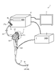
- FIG. 1 is a diagram schematically showing an overall configuration of an endoscope system according to an embodiment.
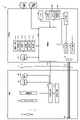
- FIG. 2 is a block diagram showing a functional configuration of a main part of the endoscope system according to the embodiment.
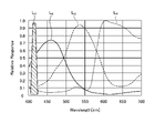
- FIG. 3 is a diagram schematically showing the wavelength characteristics of the excitation light emitted by the second light source unit according to the embodiment.
- FIG. 4 is a diagram schematically showing the transmission characteristics of the cut filter according to the embodiment.
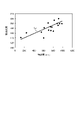
- FIG. 5 is a diagram showing an example of correlation information recorded by the correlation information recording unit according to the embodiment.
- FIG. 6 is a diagram schematically showing an observation principle in the fluorescence observation mode of the endoscope system according to the embodiment.
- FIG. 1 is a diagram schematically showing an overall configuration of an endoscope system according to an embodiment.
- FIG. 2 is a block diagram showing a functional configuration of a main part of the endoscope system according to the embodiment.
- FIG. 3 is a diagram schematically showing the wavelength characteristics of the excitation light emitted by
- FIG. 7 is a diagram schematically showing an observation principle in the normal light observation mode of the endoscope system according to the embodiment.
- FIG. 8 is a flowchart illustrating a procedure for transurethral urethral stone removal by an operator using an endoscopic system.
- FIG. 9A is a diagram showing an example of an image transition displayed by a display device in transurethral urethral stone removal.
- FIG. 9B is a diagram showing an example of an image transition displayed by a display device in transurethral urethral stone removal.
- FIG. 9C is a diagram showing an example of an image transition displayed by a display device in transurethral urethral stone removal.
- FIG. 9A is a diagram showing an example of an image transition displayed by a display device in transurethral urethral stone removal.
- FIG. 9B is a diagram showing an example of an image transition displayed by a display device in transurethral urethral stone removal.
- FIG. 9C is a diagram showing an example
- FIG. 9D is a diagram showing an example of an image transition displayed by a display device in transurethral urethral stone removal.
- FIG. 9E is a diagram showing an example of an image transition displayed by a display device in transurethral urethral stone removal.
- FIG. 9F is a diagram showing an example of an image transition displayed by a display device in transurethral urethral stone removal.
- FIG. 10 is a flowchart showing an outline of the processing executed by the endoscope system according to the embodiment.
- FIG. 11 is a diagram schematically illustrating a method of estimating whether or not the estimation unit of the endoscope system according to the embodiment places a stent.
- FIG. 12 is a diagram schematically illustrating an estimation method in which the estimation unit of the endoscope system according to the embodiment estimates the indwelling period of the stent.
- FIG. 13 is a diagram showing an example of an output screen output to the display device by the output unit of the endoscope system according to the embodiment.
- FIG. 14 is a diagram showing another example of an output screen output to the display device by the output unit of the endoscope system according to the embodiment.
- FIG. 15 is a diagram showing another example of an output screen output to the display device by the output unit of the endoscope system according to the embodiment.
- FIG. 16 is a diagram showing another example of an output screen output to the display device by the output unit of the endoscope system according to the embodiment.
- FIG. 17 is a diagram schematically showing the transmission characteristics of the cut filter according to the modified example of the embodiment.
- a flexible-scope used for transurethral urethral stone removal hereinafter, referred to as “TUL”.
- TUL transurethral urethral stone removal
- the endoscope system will be described with reference to, but the present invention is not limited to this, and can be applied to, for example, a rigid scope and a surgical robot. Moreover, this embodiment does not limit the present disclosure. Further, in the description of the drawings, the same parts will be described with the same reference numerals. Furthermore, it should be noted that the drawings are schematic, and the relationship between the thickness and width of each member, the ratio of each member, and the like are different from the reality. Further, even between the drawings, there are parts having different dimensions and ratios from each other.
- FIG. 1 is a diagram schematically showing an overall configuration of an endoscope system according to an embodiment.
- the endoscope system 1 shown in FIG. 1 takes an image of the inside of a subject by inserting an insertion part of the endoscope into the body cavity or lumen of the subject such as a patient, for example, into the urinary tract, and this image is taken.
- the display image based on the signal is displayed on the display device.
- the urinary tract is a urethra, a bladder, a ureter, a kidney, or the like, and has a tubular shape extending in the depth direction.
- a surgeon such as a doctor can use a laser irradiation device that irradiates a high-power infrared laser such as a Yttrium YAG laser via an endoscope to remove calculus in the subject.
- the crushed stones are crushed, and the crushed stones are removed with a treatment tool such as a basket catheter, and the medical device is placed in the urinary tract until a predetermined period of time.
- the medical device is any one of a stent, a catheter and an indwelling needle.
- the endoscope system 1 includes an endoscope 2, a display device 3, a control device 4, and a laser irradiation device 5.
- the endoscope 2 generates an image pickup signal (RAW data) that images the inside of the subject, and outputs the generated image pickup signal to the control device 4.
- the endoscope 2 includes an insertion unit 21, an operation unit 22, and a universal cord 23.
- the insertion portion 21 is inserted into the subject.
- the insertion portion 21 has an elongated shape having flexibility.
- the insertion portion 21 is connected to a tip portion 24 having a built-in image pickup element, which will be described later, a bendable bending portion 25 composed of a plurality of bending pieces, and a base end side of the bending portion 25, and has a flexible length. It has a scale-shaped flexible tube portion 26 and.
- the tip portion 24 is configured by using glass fiber or the like.
- the tip portion 24 serves as a light guide path for the illumination light supplied from the control device 4 via the universal cord 23 and the operation unit 22, and generates an image pickup signal that captures the return light of the illumination light to control the control device 4. Output to.
- the operation unit 22 includes a bending knob 221 that bends the curved portion 25 in the vertical and horizontal directions, a treatment tool insertion section 222 for inserting a body treatment tool, and a control device 4, as well as an air supply means, a water supply means, and a power supply.
- Multiple switches that are operation input units that input operation instruction signals for peripheral devices such as gas means, prefreeze signals for instructing the endoscope system 1 to shoot still images, or switching signals for switching the observation mode of the endoscope system 1. 223 and.
- the treatment tool inserted from the treatment tool insertion portion 222 is exposed from the opening (not shown) via the treatment tool channel (not shown) of the tip portion 24.
- the treatment tool includes a laser irradiation device 5, a basket catheter, and the like.
- the universal cord 23 has at least a built-in light guide and a condensing cable that bundles one or more cables.
- the collective cable is a signal line for transmitting and receiving signals between the endoscope 2 and the control device 4, and is for driving a signal line for transmitting and receiving an image pickup signal (RAW data) and an image pickup element described later. Includes signal lines for transmitting and receiving timing signals (synchronization signals and clock signals).
- the universal cord 23 has a connector portion 27 detachable from the control device 4, a coil-shaped coil cable 27a extending, and a connector portion 28 detachable from the control device 4 at the extending end of the coil cable 27a. ..
- the display device 3 displays a display image based on the video signal input from the control device 4 under the control of the control device 4.
- the display device 3 is realized by using a display panel such as an organic EL (Electro Luminescence) or a liquid crystal display.
- control device configuration controls each part of the endoscope system 1.
- the control device 4 supplies illumination light for the endoscope 2 to irradiate the subject. Further, the control device 4 performs various image processing on the image pickup signal input from the endoscope 2 and outputs the image processing to the display device 3.
- the laser irradiation device 5 is inserted into the body of the subject, for example, the urinary tract (for example, kidney, ureter, bladder and urethra) via the treatment tool insertion portion 222 of the endoscope 2, and is operated by the operator.
- the stones are crushed by irradiating the stones generated in the subject with a high-power infrared laser such as a formium YAG laser.
- FIG. 2 is a block diagram showing a functional configuration of a main part of the endoscope system 1.
- the endoscope 2 includes an illumination optical system 201, an image pickup optical system 202, a cut filter 203, an image pickup element 204, an A / D conversion unit 205, a P / S conversion unit 206, an image pickup recording unit 207, and the like.
- An image pickup control unit 208 is provided.
- the illumination optical system 201, the image pickup optical system 202, the cut filter 203, the image sensor 204, the A / D conversion unit 205, the P / S conversion unit 206, the image pickup recording unit 207, and the image pickup control unit 208 each have a tip portion 24. It is placed inside.
- the illumination optical system 201 irradiates the subject (living tissue) with the illumination light supplied from the light guide 231 formed of an optical fiber or the like.
- the illumination optical system 201 is realized by using one or more lenses or the like.
- the image pickup optical system 202 collects a subject image (light ray) on the light receiving surface of the image pickup element 204 by condensing light such as reflected light reflected from the subject, return light from the subject, and fluorescence emitted by the subject. Image is formed on.
- the image pickup optical system 202 is realized by using one or more lenses or the like.
- the cut filter 203 is arranged on the optical axis O1 of the image pickup optical system 202 and the image pickup element 204.
- the cut filter 203 is the excitation light supplied from the control device 4 described later, and shields the light in the wavelength band of the reflected light or the return light of the excitation light from the subject, and is on the longer wavelength side than the wavelength band of the excitation light. Transmits light in the wavelength band of.
- the transmission characteristics of the cut filter 203 will be described later.
- the image sensor 204 receives a subject image (light ray) formed by the image pickup optical system 202 under the control of the image pickup control unit 208 and has passed through the cut filter 203, and performs photoelectric conversion. To generate an image pickup signal (RAW data) and output it to the A / D conversion unit 205.
- the image pickup device 204 is a CCD (Charge Coupled Device) or CMOS (Complementary) in which any one of the color filters constituting the Bayer array (RGGB) is arranged in each of a plurality of pixels arranged in a two-dimensional matrix. It is realized by using the image sensor of Metal Oxide Semiconductor.
- the A / D conversion unit 205 Under the control of the image pickup control unit 208, the A / D conversion unit 205 performs A / D conversion processing on the analog image pickup signal input from the image pickup element 204 and outputs the analog image pickup signal to the P / S conversion unit 206.
- the A / D conversion unit 205 is realized by using an A / D conversion circuit or the like.
- the P / S conversion unit 206 Under the control of the image pickup control unit 208, the P / S conversion unit 206 performs parallel / serial conversion on the digital image pickup signal input from the A / D conversion unit 205, and performs the parallel / serial conversion on the image pickup signal. Is output to the control device 4 via the first transmission cable 232.
- the P / S conversion unit 206 is realized by using a P / S conversion circuit or the like.
- an E / O conversion unit that converts the image pickup signal into an optical signal is provided, and the image pickup signal is output to the control device 4 by the optical signal.
- the image pickup signal may be transmitted to the control device 4 by wireless communication such as Wi-Fi (Wireless Fidelity) (registered trademark).
- the image pickup recording unit 207 records various information regarding the endoscope 2 (for example, pixel information of the image pickup element 204, characteristics of the cut filter 203). Further, the image pickup recording unit 207 records various setting data and control parameters transmitted from the control device 4 via the second transmission cable 233.
- the image pickup recording unit 207 is configured by using a non-volatile memory or a volatile memory.
- the image pickup control unit 208 operates each of the image pickup element 204, the A / D conversion unit 205, and the P / S conversion unit 206 based on the setting data received from the control device 4 via the second transmission cable 233. Control.
- the image pickup control unit 208 is realized by using a TG (Timing Generator), a processor which is a processing device having hardware such as a CPU, and a memory which is a temporary storage area used by the processor.
- the control device 4 includes a condenser lens 401, a first light source unit 402, a second light source unit 403, a light source control unit 404, an S / P conversion unit 405, an image processing unit 406, and an input unit 407. And a recording unit 408 and a control unit 409.
- the condenser lens 401 collects the light emitted by each of the first light source unit 402 and the second light source unit 403 and emits it to the light guide 231.
- the condenser lens 401 is configured using one or more lenses.
- the first light source unit 402 supplies white light to the light guide 231 by emitting white light (normal light) which is visible light under the control of the light source control unit 404.
- the first light source unit 402 is configured by using a collimating lens, a white LED (Light Emitting Diode) lamp, a drive driver, and the like.
- the first light source unit 402 may supply visible white light by simultaneously emitting light using a red LED lamp, a green LED lamp, and a blue LED lamp.
- the first light source unit 402 may be configured by using a halogen lamp, a xenon lamp, or the like.
- the second light source unit 403 emits excitation light having a predetermined wavelength band to supply narrow band light to the light guide 231 as illumination light.
- the excitation light has a wavelength band of 400 nm to 430 nm (center wavelength is 415 nm).
- the second light source unit 403 is realized by using a collimating lens, a semiconductor laser such as a purple LD (laser Diode), a drive driver, or the like.
- a collimating lens a semiconductor laser such as a purple LD (laser Diode)
- a drive driver or the like.
- the light source control unit 404 uses a processor, which is a processing device having hardware such as an FPGA (Field-Programmable Gate Array) or a CPU (Central Processing Unit), and a memory, which is a temporary storage area used by the processor. It is composed of.
- the light source control unit 404 controls the light emission timing, light emission intensity, light emission time, etc. of each of the first light source unit 402 and the second light source unit 403 based on the control data input from the control unit 409.
- the S / P conversion unit 405 Under the control of the control unit 409, the S / P conversion unit 405 performs serial / parallel conversion on the image pickup signal received from the endoscope 2 via the first transmission cable 232, and performs serial / parallel conversion to the image processing unit 406. Output to.
- an O / E conversion unit that converts the optical signal into an electric signal may be provided instead of the S / P conversion unit 405.
- a communication module capable of receiving the wireless signal may be provided instead of the S / P conversion unit 405.
- the image processing unit 406 is realized by using a processor having hardware such as a CPU, GPU (Graphics Processing Unit) or FPGA, and a memory which is a temporary storage area used by the processor. Under the control of the control unit 409, the image processing unit 406 performs predetermined image processing on the image pickup signal input from the S / P conversion unit 405 and outputs it to the display device 3. In one embodiment, the image processing unit 406 functions as a support device.
- the image processing unit 406 includes a generation unit 406a, a calculation unit 406c, an extraction unit 406b, an estimation unit 406d, and an output unit 406e.
- the generation unit 406a generates a fluorescence image based on an imaging signal generated by imaging the fluorescence generated by the excitation light irradiating the living tissue. Specifically, the generation unit 406a inputs an image pickup signal from the image pickup element 204 of the endoscope 2, an A / D conversion unit 205, a P / S conversion unit 206, a first transmission cable 232, and an S / P conversion unit 405. (Hereinafter, it is simply described as "acquired from the image pickup element 204 of the endoscope 2").
- the generation unit 406a is an image pickup signal acquired from the image pickup element 204 of the endoscope 2, and fluorescence is based on the image pickup signal generated by imaging the fluorescence generated by the excitation light applied to the living tissue. Generate an image. Further, the generation unit 406a is an observation image (white) which is a display image based on an image pickup signal generated by imaging the reflected light and the return light reflected from the living body tissue by irradiating the living body tissue with white light. Optical image) is generated.
- Extraction unit 406b extracts the fluorescence region from the fluorescence image. Specifically, the extraction unit 406b extracts the fluorescence region by performing a binarization process on each pixel of the fluorescence image. For example, the extraction unit 406b extracts a fluorescence region by extracting pixels having a predetermined value or more with respect to the pixel value of each pixel of the fluorescence image.
- the calculation unit 406c calculates the fluorescence intensity based on the fluorescence image generated by the generation unit 406a. Specifically, the calculation unit 406c calculates the fluorescence intensity of the fluorescent region of the fluorescent image generated by the generation unit 406a and extracted by the extraction unit 406b.
- the estimation unit 406d estimates the indwelling period of the medical device to be indwelled in the lumen based on the fluorescence intensity calculated by the calculation unit 406c.
- the lumen is the urinary tract.
- the urinary tract also includes the urethra, bladder, ureter and kidneys.
- the medical device is any one of a stent, a catheter and an indwelling needle.
- the estimation unit 406d estimates the degree of invasion of the living tissue by the energy device based on the fluorescence intensity calculated by the calculation unit 406c, and estimates the indwelling period of the medical device based on this degree of invasion.
- the estimation unit 406d is based on the correlation information recording the correlation between the invasiveness and the fluorescence intensity recorded by the correlation information recording unit 408b, which will be described later, and the fluorescence intensity calculated by the calculation unit 406c. Estimate the degree of invasion of the tissue by the energy device.
- the output unit 406e outputs the indwelling period information regarding the indwelling period of the medical device estimated by the estimation unit 406d and the observation image as a display image of the living tissue to the display device 3.
- the input unit 407 receives inputs for various operations related to the endoscope system 1 and outputs the accepted operations to the control unit 409.
- the input unit 407 is configured by using a mouse, a foot switch, a keyboard, a button, a switch, a touch panel, and the like.
- the recording unit 408 is realized by using a recording medium such as a volatile memory, a non-volatile memory, an SSD (Solid State Drive), an HDD (Hard Disk Drive), or a memory card.
- the recording unit 408 records data including various parameters necessary for the operation of the endoscope system 1.
- the recording unit 408 includes a program recording unit 408a for recording various programs for operating the endoscope system 1 and a correlation information recording unit 408b.
- the correlation information recording unit 408b correlates between the degree of invasiveness of the biological tissue of the subject by the laser irradiation device 5 and the fluorescence intensity emitted when the biological tissue heat-treated by the laser irradiation device 5 is irradiated with excitation light. Record the correlation information that indicates the relationship. The details of the correlation information will be described later.
- the control unit 409 is realized by using a processor having hardware such as FPGA or CPU and a memory which is a temporary storage area used by the processor.
- the control unit 409 comprehensively controls each unit constituting the endoscope system 1.
- FIG. 3 is a diagram schematically showing the wavelength characteristics of the excitation light emitted by the second light source unit 403.
- the horizontal axis indicates the wavelength (nm)
- the vertical axis indicates the wavelength characteristic.
- the polygonal line LV shows the wavelength characteristic of the excitation light emitted by the second light source unit 403.
- the curve LB indicates a blue wavelength band
- the curve LG indicates a green wavelength band
- the curve LR indicates a red wavelength band.
- the second light source unit 403 emits excitation light having a center wavelength (peak wavelength) of 415 nm and a wavelength band of 400 nm to 430 nm.
- FIG. 4 is a diagram schematically showing the transmission characteristics of the cut filter 203.
- the horizontal axis indicates the wavelength (nm), and the vertical axis indicates the transmission characteristic.
- the broken line LF shows the transmission characteristic of the cut filter 203
- the broken line LV shows the wavelength characteristic of the excitation light
- the broken line NG shows the heat treatment of the living tissue by an energy device, for example, a laser irradiation device 5. The wavelength characteristics of fluorescence generated by irradiating the resulting terminal saccharification product with excitation light are shown.
- the cut filter 203 shields a part of the excitation light reflected from the living tissue in the observation region and transmits light in other wavelength bands including a fluorescent component. do. Specifically, the cut filter 203 shields a part of the light in the wavelength band on the short wavelength side of 400 nm to less than 430 nm including the excitation light, and irradiates the terminal saccharified product produced by the heat treatment with the excitation light. It transmits light in a wavelength band longer than 430 nm, including fluorescence generated by this.
- FIG. 5 is a diagram showing an example of correlation information recorded by the correlation information recording unit 408b.
- the vertical axis shows the emission intensity
- the horizontal axis shows the degree of invasion (depth and region) into the living tissue by the heat treatment.
- the straight line Ly indicates the correlation between the luminescence intensity and the degree of invasion (depth and region) of the living tissue by the heat treatment.
- the luminescence intensity becomes stronger as the degree of invasion to the living tissue by the heat treatment is larger.
- FIG. 6 is a diagram schematically showing the observation principle in the fluorescence observation mode.
- the control device 4 causes the second light source unit 403 to emit light, so that the excitation light (center wavelength 415 nm) is heat-treated by the laser irradiation device 5 with respect to the subject. Irradiate the applied biological tissue O10 (heat treatment area).
- the reflected light including at least the components of the excitation light reflected by the biological tissue O10 (heat treatment region) and the return light (hereinafter, simply referred to as “reflected light W10”) is While the cut filter 203 shields light from light and reduces the intensity, some of the components on the wavelength side longer than the wavelength band that shields most of the light are incident on the image sensor 204 without reducing the intensity.
- the cut filter 203 is the reflected light W10 incident on the G pixel, and is the reflected light W10 having a short wavelength band including the wavelength band of the excitation light. Most of it is shielded from light, and the wavelength band on the longer wavelength side than the wavelength band that shields most of this light is transmitted. Further, as shown in the graph G12 of FIG. 6, the cut filter 203 transmits the fluorescence (WF10) that the AGEs in the living tissue O10 (heat treatment region) self-emit. Therefore, the reflected light W10 and the fluorescence (WF10) having reduced intensities are incident on each of the R pixel, the G pixel, and the B pixel.
- WF10 fluorescence
- the G pixel has sensitivity to fluorescence, but the output value is small because the fluorescence is a minute reaction.
- the image processing unit 406 acquires an image pickup signal (RAW data) from the image pickup element 204 of the endoscope 2, and performs image processing on each signal value of the G pixel and the B pixel included in the acquired image pickup signal.
- the signal value of the G pixel includes the fluorescence information emitted from the heat treatment region.
- the B pixel contains background information from the biological tissue of the subject including the heat treatment region.
- the image processing unit 406 performs demosaic processing, processing for calculating the intensity ratio for each pixel, processing for determining between the fluorescent region and the background region, and the color component signal (pixel value) and the background region of the pixels located in the fluorescent region.
- the image processing unit 406 outputs the fluorescent image to the display device 3.
- the fluorescence region is a region in which fluorescence information is superior to background information.
- the background region refers to a region where the background information is superior to the fluorescence information.
- the intensity ratio of the reflected light component signal corresponding to the background information and the fluorescence component signal corresponding to the fluorescence information contained in the pixel is equal to or higher than a predetermined threshold value (for example, 0. If it is 5 or more), it is determined to be a fluorescent region, while if the intensity ratio is less than a predetermined threshold value, it is determined to be a background region to extract the fluorescent region and the background region.
- the biological tissue (heat treatment region) heat-treated by the laser irradiation device 5 can be easily observed.
- FIG. 7 is a diagram schematically showing the observation principle in the normal light observation mode.
- the control device 4 irradiates the living tissue O10 of the subject with white light W3 by causing the first light source unit 402 to emit light.
- a part of the reflected light and the return light reflected by the living tissue O10 (hereinafter, simply referred to as "reflected light WR30, reflected light WG30, reflected light WB30") is shielded by the cut filter 203, and the rest is an image pickup element. It is incident on 204.
- the cut filter 203 shields reflected light in a short wavelength wavelength band including a narrow band light wavelength band. Therefore, as shown in FIG. 7, the light component in the blue wavelength band incident on the B pixel is smaller than that in the state where the cut filter 203 is not arranged.
- the image processing unit 406 acquires an image pickup signal (RAW data) from the image pickup element 204, and performs image processing on each signal value of the R pixel, the G pixel, and the B pixel included in the acquired image pickup signal.
- An observation image (white light image), which is a display image, is generated.
- the image processing unit 406 adjusts the white balance so that the ratios of the red component, the green component, and the blue component are constant because the blue component contained in the image pickup signal is smaller than that of the conventional white light observation. Perform white balance adjustment processing.
- a natural observation image (white image) can be observed even when the cut filter 203 is arranged.
- FIG. 8 is a flowchart illustrating a procedure method of transurethral urethral stone removal (f-TUL) by the operator using the endoscope system 1.
- 9A-9F are diagrams showing an example of image transitions displayed by the display device 3 in transurethral urethral stone removal (f-TUL).
- the surgeon first inserts the insertion portion 21 of the endoscope 2 into the urinary tract (ureter) of the subject while irradiating the endoscope 2 with white light (normal light) (as shown in FIG. 8).
- Step S1 the operator inserts the insertion portion 21 of the endoscope 2 into the urinary tract of the subject while observing the observation image P1 by the white light displayed on the display device 3.
- the surgeon confirms the calculus generated in the subject while looking at the observation image P1 displayed on the display device 3 (step S2).
- the surgeon inserts the insertion portion 21 of the endoscope 2 into the urinary tract of the subject while observing the observation image P2 displayed on the display device 3, and observes the image.
- searching for calculus K1 while observing P2 confirm the size and position of calculus K1.
- the surgeon inserts the laser irradiation device 5 into the urinary tract of the subject via the treatment tool insertion portion 222 of the endoscope 2 while looking at the observation image displayed on the display device 3, and directs the laser irradiation device toward the calculus. And irradiate the laser (step S3).
- the operator crushes the calculus K1 by irradiating the calculus K1 with a laser by the laser irradiation device 5 while observing the observation image P3 displayed on the display device 3. ..
- the surgeon extracts the calculus crushed by the basket via the treatment tool insertion portion 222 of the endoscope 2 from the subject while observing the observation image displayed on the display device 3 (step S4).
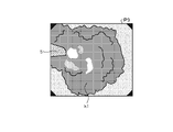
- the operator grasps the observation image P4 or the observation image P5 displayed on the display device 3 via the treatment tool insertion portion 222 of the endoscope 2.
- a possible treatment tool such as a calculus K1 crushed by a basket catheter K2, is removed from the subject.
- the operator operates the operation unit of the endoscope 2 to switch the observation mode irradiated by the endoscope 2 from the normal light observation mode to the fluorescence observation mode (heat treatment observation mode) (step S5).
- the control device 4 emits the excitation light toward the subject by emitting light from the second light source unit 403.
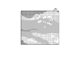
- the operator grasps the degree of burn invasion by the laser irradiation device 5 by observing the fluorescence region Q1 included in the fluorescence image P6 displayed on the display device 3.
- the operator operates the operation unit 22 of the endoscope 2 to alternately switch the observation mode of the endoscope 2 between the fluorescence observation mode and the normal light observation mode, and the laser irradiation device 5 is used to apply the laser irradiation device to the surrounding tissue.
- the degree of invasion of the burn is grasped (step S6).
- the operator determines the indwelling and indwelling period of the stent with reference to whether or not the stent displayed by the display device 3 is indwelled and the indwelling period (step S7).
- the control device 4 displays on the display device 3 whether or not the stent is placed in the urinary tract and the indwelling period information regarding the indwelling period based on the emission intensity of the light emitting region included in the fluorescence image P6. Output on the observation image.
- the surgeon determines whether or not to indwell the stent in the urinary tract and the indwelling period with reference to the indwelling period information displayed on the display device 3.
- the presence or absence of indwelling a stent in the urinary tract displayed by the control device 4 on the display device 3 and the method of estimating the indwelling period will be described later.
- step S8 the operator places the stent in the urinary tract. After that, the operator removes the endoscope 2 from the urinary tract of the subject and completes the procedure.
- the surgeon crushes the calculus located in the urinary tract of the subject with a laser, removes the crushed stone from the subject with a treatment tool or the like, and then sets the observation mode of the endoscope system 1 to normal light.
- the observation mode By switching from the observation mode to the fluorescence observation mode and grasping the degree of laser invasion of the living tissue of the subject, the presence or absence of stent placement and the placement period are determined.
- FIG. 10 is a flowchart showing an outline of the process executed by the endoscope system 1.
- control unit 409 controls the light source control unit 404 to cause the first light source unit 402 to emit light, thereby irradiating the subject with white light (step S101).
- the image processing unit 406 acquires an image pickup signal from the image pickup element 204 of the endoscope 2, generates an observation image as a display image, and outputs the observation image to the display device 3 (step S102).
- control unit 409 determines whether or not a change signal for changing the observation mode to the fluorescence observation mode is input from the input unit 407 or the operation unit 22 of the endoscope 2 (step S103).
- step S103 determines whether or not a change signal for changing the observation mode to the fluorescence observation mode is input from the input unit 407 or the operation unit 22 of the endoscope 2 (step S103: Yes).
- step S104 determines whether or not a change signal for changing the observation mode to the fluorescence observation mode is input from the input unit 407 or the operation unit 22 of the endoscope 2
- step S103 when the change signal for changing to the observation mode fluorescence observation mode is not input from the input unit 407 or the operation unit 22 of the endoscope 2 by the control unit 409 (step S103: No), the endoscope system 1 Goes to step S120, which will be described later.
- step S104 the control unit 409 controls the light source control unit 404 to irradiate the second light source unit 403 with the excitation light.
- the image processing unit 406 generates a fluorescent image based on the image pickup signal generated by the image pickup element 204 of the endoscope 2 (step S105).
- the extraction unit 406b extracts the fluorescence region included in the fluorescence image generated by the generation unit 406a (step S106). Specifically, the extraction unit 406b extracts the fluorescence region by performing binarization processing or the like on the fluorescence image. When the fluorescent image contains a plurality of fluorescent regions, the extraction unit 406b extracts the plurality of fluorescent regions.
- the calculation unit 406c calculates the fluorescence intensity of the fluorescence region extracted by the extraction unit 406b (step S106). In this case, when the extraction unit 406b extracts a plurality of fluorescence regions, the calculation unit 406c calculates the fluorescence intensity of each of the plurality of fluorescence regions.
- the estimation unit 406d determines whether or not there are a plurality of fluorescent regions (step S108).
- the estimation unit 406d determines that there are a plurality of fluorescence regions (step S108: Yes)
- the endoscope system 1 proceeds to step S109 described later.
- the estimation unit 406d determines that the number of fluorescent regions is not plural (step S108: No)
- the endoscope system 1 shifts to step S110 described later.
- step S109 the estimation unit 406d places a stent in the urinary tract based on the strongest emission intensity from the plurality of fluorescence regions calculated by the calculation unit 406c and the correlation information recorded by the correlation information recording unit 408b. Estimate whether or not to detain. Specifically, as shown in FIG. 11, the estimation unit 406d places a stent in the urinary tract based on the correlation information recorded by the correlation information recording unit 408b and the emission intensity calculated by the calculation unit 406c. Estimate whether or not to do. For example, as shown in FIG.
- the estimation unit 406d determines the value of the emission intensity that does not require stent placement based on the correlation information recorded by the correlation information recording unit 408b and the emission intensity calculated by the calculation unit 406c. It is determined whether or not the indicated threshold value is less than TL1, and if the emission intensity is less than the threshold value TL1, it is presumed that the placement of the stent in the urinary tract is unnecessary. On the other hand, the estimation unit 406d is in the urinary tract when the emission intensity is equal to or higher than the threshold value TL1 based on the correlation information recorded by the correlation information recording unit 408b and the emission intensity calculated by the calculation unit 406c. It is presumed that stent placement is necessary. After step S109, the endoscope system 1 shifts to step S111 described later.
- step S110 the estimation unit 406d estimates whether or not to place the stent based on the emission intensity calculated by the calculation unit 406c and the correlation information recorded by the correlation information recording unit 408b.
- step S110 the endoscope system 1 shifts to step S111 described later.
- step S111 when it is estimated that the stent is placed in the urinary tract by the estimation unit 406d (step S111: Yes), the endoscope system 1 shifts to step S112 described later.
- step S111: No when the estimation unit 406d specifies that the stent is to be placed in the urinary tract (step S111: No), the endoscope system 1 shifts to step S114 described later.
- the estimation unit 406d estimates the indwelling period of the stent in the urinary tract based on the emission intensity calculated by the calculation unit 406c and the correlation information recorded by the correlation information recording unit 408b. Specifically, as shown in FIG. 12, the estimation unit 406d places a stent in the urinary tract based on the emission intensity calculated by the calculation unit 406c and the correlation information recorded by the correlation information recording unit 408b. Estimate the period. For example, as shown in FIG. 12, the estimation unit 406d has a correlation between the emission intensity and the degree of invasiveness based on the emission intensity calculated by the calculation unit 406c and the correlation information recorded by the correlation information recording unit 408b.
- the indwelling period of the stent When located in the first region Z1 (Low), the indwelling period of the stent is estimated to be short, and when the correlation between the luminescence intensity and the degree of invasiveness is located in the second region Z2 (middlee), the indwelling period of the stent is estimated. Is estimated to be normal, and when the correlation between the emission intensity and the degree of invasiveness is located in the third region Z3 (High), it is estimated that the indwelling period of the stent is longer.
- the short term is about several days
- the normal term is about one week
- the long term is 10 days or more.
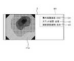
- the output unit 406e outputs the indwelling period information to the display device 3 (step S113). Specifically, as shown in FIG. 13, the output unit 406e outputs the indwelling period information M1 and the observation image P10 which is a display image to the display device 3.
- the indwelling period information M1 includes a maximum invasiveness m1 (maximum invasion depth based on fluorescence intensity), a presence / absence of stent placement m2, and a recommended placement period m3 of the stent.
- the control unit 409 determines whether or not a change signal for changing the observation mode to the normal light observation mode is input from the input unit 407 or the operation unit 22 of the endoscope 2 (step S114).
- a change signal for changing the observation mode to the normal light observation mode is input from the input unit 407 or the operation unit 22 of the endoscope 2 (step S114: Yes)
- the endoscope system 1 The process proceeds to step S115 described later.
- the control unit 409 determines whether or not a change signal for changing the observation mode to the normal light observation mode is input from the input unit 407 or the operation unit 22 of the endoscope 2 (step S114: Yes).
- the endoscope system 1 returns to step S104 described above.
- step S115 the control unit 409 controls the light source control unit 404 to cause the first light source unit 402 to emit light to irradiate white light.
- the image processing unit 406 acquires an image pickup signal from the image pickup element 204 of the endoscope 2, generates an observation image, and outputs the observation image to the display device 3 (step S116). Specifically, the generation unit 406a acquires an image pickup signal from the image pickup element 204 and generates an observation image based on the image pickup signal.
- the control unit 409 determines whether or not the living tissue has been invaded by the laser by the estimation unit 406d (step S117). Specifically, the control unit 409 determines whether or not the estimation unit 406d estimates that the stent is to be placed in the urinary tract, and if the estimation unit 406d estimates that the stent is to be placed in the urinary tract, the living tissue. On the other hand, it is judged that there was an invasion by the laser. When the control unit 409 determines that the living tissue has been invaded by the laser (step S117: Yes), the endoscope system 1 proceeds to step S118 described later. On the other hand, when the control unit 409 determines that the living tissue has been invaded by the laser (step S117: No), the endoscope system 1 proceeds to step S119, which will be described later.
- step S118 the output unit 406e superimposes the indwelling period information indicating the presence / absence of indwelling and the indwelling period of the stent estimated by the estimation unit 406d on the observation image generated by the generation unit 406a and outputs it to the display device 3.
- the endoscope system 1 shifts to step S120 described later.
- step S119 the output unit 406e outputs the observation image generated by the generation unit 406a to the display device 3.
- step S119 the endoscope system 1 shifts to step S120 described later.
- step S120 the control unit 409 determines whether or not an end signal for terminating the observation of the subject has been input from the input unit 407 or the operation unit 22 of the endoscope 2.
- step S120: Yes the endoscope system 1 performs this process.
- step S120: No the endoscope is viewed.
- the mirror system 1 returns to step S101 described above.
- the estimation unit 406d estimates the indwelling period of the medical device to be indwelled in the lumen based on the fluorescence intensity calculated by the calculation unit 406c, and the output unit 406e estimates the estimation unit 406d.
- the indwelling period information regarding the indwelling period estimated by the above and the observation image of the living tissue to the display device 3 the indwelling period when the medical device is indwelled in the lumen should be objectively grasped. Can be done.
- the estimation unit 406d estimates the degree of invasion of the living tissue by the energy device based on the fluorescence intensity calculated by the calculation unit 406c, and estimates the indwelling period based on this degree of invasion. Therefore, it is possible to objectively grasp the indwelling period when the medical device is indwelled in the lumen.
- the estimation unit 406d estimates the degree of invasiveness based on the correlation information recorded by the correlation information recording unit 408b and the fluorescence intensity calculated by the calculation unit 406c. The actual degree of invasion to the tissue can be estimated.
- a user such as an operator can estimate whether or not the medical device is to be placed in the lumen based on the fluorescence intensity calculated by the calculation unit 406c by the estimation unit 406d. It is possible to objectively grasp whether or not it is necessary to place the medical device in the lumen.
- the medical device when a plurality of fluorescent regions are extracted by the estimation unit 406d by the extraction unit 406b, the medical device is placed in the lumen based on the strongest fluorescence intensity among the plurality of fluorescent regions. To estimate the detention period of. The most relevant information can be assisted in the context of a series of procedures.
- the output unit 406e outputs the observation image, the indwelling period information, and the display device 3, but for example, the attention period information is superimposed on the observation image and output to the display device 3. May be good.
- the output unit 406e outputs the indwelling period information to the display device 3, but the estimation unit 406d estimates, for example, the invasion of the living tissue by the laser irradiation device 5. If so, it may be output that the invasion to the living tissue is detected. Specifically, as shown in FIG. 14, the output unit 406e displays the invasion information M10 indicating that the estimation unit 406d has detected the invasion of the living tissue when the estimation unit 406d estimates the invasion of the living tissue by the laser irradiation device 5. It may be output to the device 3. As a result, the operator can grasp the invasion of the living tissue by the laser irradiation device 5.
- the output unit 406e outputs the indwelling period information to the display device 3, but the calculation unit 406c is not limited to this, and for example, the calculation unit 406c calculates the emission intensity of each of the plurality of fluorescence regions. If so, the degree of invasion of each fluorescent region may be output to the display device 3 so as to be discriminating. Specifically, as shown in FIG. 15, the output unit 406e is superimposed on the observation image P30 in a display mode corresponding to the emission intensity of each of the plurality of fluorescence regions Q11 to Q13 calculated by the calculation unit 406c, and is invaded. The depth information M20 and the indwelling period information M1 regarding the depth may be combined and output to the display device 3.
- the estimation unit 406d is based on the emission intensity of the fluorescence region Q12 on the near point side of the emission intensity of the fluorescence regions Q11 and Q13 on the far point side among the plurality of fluorescence regions Q11 to Q13 in the region H1 shown in FIG. , Estimate the presence or absence of stent placement and the duration of placement.
- the estimation unit 406d determines whether or not the brightness information of each pixel of the observation image (white light image) is equal to or higher than a predetermined threshold value as the determination method for the far point side and the near point side.
- a pixel having a predetermined threshold value or more is estimated as the near point side
- a pixel having a predetermined threshold value or less is estimated as the far point side, thereby estimating the far point side and the near point side.
- the output unit 406e may output only to the display device 3 that the living tissue is invaded by the energy device. good.
- the calculation unit 406c calculates the fluorescence intensity by performing amplification processing by gain or the like on the signal value of the pixel located in the fluorescence region. May be good.
- the operator switches the observation mode by operating the input unit 407 or the operation unit 22, and switches between the observation image and the fluorescence image, but a predetermined frame rate (for example, 60 fps). ),
- the excitation light may be automatically switched and irradiated every predetermined frame (for example, 10 fps) to acquire a fluorescent image.
- the output unit 406e outputs the observation image to the display device 3 and displays the invasion information M10 indicating that the invasion to the living tissue is detected only when the degree of invasion by the energy device is estimated by the estimation unit 406d. It may be output to the device 3.
- the estimation unit 406d estimates whether or not to indwell the stent and estimates the indwelling period of the stent in the urinary tract, but the estimation is not limited to this, and for example, estimation. Only one of the estimation of whether or not the stent is indwelled by the part 406d and the estimation of the indwelling period of the stent in the urinary tract may be performed. Of course, the estimation unit 406d only estimates whether or not to indwell the stent according to the operation of the operator's input unit 407 or the operation unit 22, and estimates the indwelling period of the stent in the urinary tract. You may go.
- FIG. 17 is a diagram schematically showing the transmission characteristics of the cut filter according to the modified example of the embodiment.
- the horizontal axis indicates the wavelength (nm)
- the vertical axis indicates the transmission characteristic.
- the broken line LFf shows the transmission characteristic of the cut filter 203A
- the broken line LV shows the wavelength characteristic of the excitation light
- the broken line NG shows the heat treatment of the living tissue by an energy device, for example, a laser irradiation device 5.
- the wavelength characteristics of fluorescence generated by irradiating the resulting terminal saccharification product with excitation light are shown.
- the cut filter 203A transmits a part of the excitation light reflected from the living tissue in the observation region and transmits only the fluorescent component.
- the cut filter 203A is generated by blocking light in a wavelength band on the short wavelength side of 400 nm to less than 430 nm including excitation light, and irradiating the terminal saccharified product produced by heat treatment with excitation light. It transmits light in a wavelength band longer than 430 nm, including fluorescence.
- Various inventions can be formed by appropriately combining a plurality of components disclosed in the endoscope system according to the above-described embodiment. For example, some components may be deleted from all the components described in the endoscope system according to the above-described embodiment. Further, the components described in the endoscope system according to the above-described embodiment may be appropriately combined.
- the first light source unit, the second light source unit, and the light source control unit are integrally provided in the control device, but the present invention is not limited to this, and for example, the first light source unit is provided.
- a light source device including a unit, a second light source, and a light source control unit, and a control device may be provided separately.
- the endoscope system uses a flexible endoscope, but the present invention is not limited to this, and the endoscope system using a rigid endoscope and a plurality of rigid endoscopes are used. And it can also be applied to a medical surgical robot or a medical observation system using a laser irradiation device.
- the above-mentioned "part” can be read as “means” or "circuit".
- the control unit can be read as a control means or a control circuit.
- a switching step to switch the observation method of the endoscope to fluorescence observation An observation step of observing the inside of the subject by fluorescence observation, After the observation by the fluorescence observation, the indwelling step of indwelling the stent and the indwelling step including, A procedure for transurethral urethral stone removal using an endoscopic system.
Landscapes
- Health & Medical Sciences (AREA)
- Life Sciences & Earth Sciences (AREA)
- Surgery (AREA)
- Engineering & Computer Science (AREA)
- Biomedical Technology (AREA)
- Veterinary Medicine (AREA)
- General Health & Medical Sciences (AREA)
- Heart & Thoracic Surgery (AREA)
- Public Health (AREA)
- Animal Behavior & Ethology (AREA)
- Biophysics (AREA)
- Medical Informatics (AREA)
- Molecular Biology (AREA)
- Physics & Mathematics (AREA)
- Radiology & Medical Imaging (AREA)
- Nuclear Medicine, Radiotherapy & Molecular Imaging (AREA)
- Optics & Photonics (AREA)
- Pathology (AREA)
- Vascular Medicine (AREA)
- Cardiology (AREA)
- Transplantation (AREA)
- Oral & Maxillofacial Surgery (AREA)
- Signal Processing (AREA)
- Endoscopes (AREA)
Priority Applications (4)
| Application Number | Priority Date | Filing Date | Title |
|---|---|---|---|
| PCT/JP2020/036945 WO2022070262A1 (ja) | 2020-09-29 | 2020-09-29 | 支援装置、内視鏡システム、支援方法およびプログラム |
| CN202080105586.1A CN116249504B (zh) | 2020-09-29 | 2020-09-29 | 辅助装置、内窥镜系统、辅助方法以及存储介质 |
| JP2022553265A JP7434591B2 (ja) | 2020-09-29 | 2020-09-29 | 支援装置、内視鏡システム、支援方法およびプログラム |
| US18/119,512 US12599293B2 (en) | 2020-09-29 | 2023-03-09 | Assist device, endoscope system, assist method and computer-readable recording medium |
Applications Claiming Priority (1)
| Application Number | Priority Date | Filing Date | Title |
|---|---|---|---|
| PCT/JP2020/036945 WO2022070262A1 (ja) | 2020-09-29 | 2020-09-29 | 支援装置、内視鏡システム、支援方法およびプログラム |
Related Child Applications (1)
| Application Number | Title | Priority Date | Filing Date |
|---|---|---|---|
| US18/119,512 Continuation US12599293B2 (en) | 2020-09-29 | 2023-03-09 | Assist device, endoscope system, assist method and computer-readable recording medium |
Publications (1)
| Publication Number | Publication Date |
|---|---|
| WO2022070262A1 true WO2022070262A1 (ja) | 2022-04-07 |
Family
ID=80951541
Family Applications (1)
| Application Number | Title | Priority Date | Filing Date |
|---|---|---|---|
| PCT/JP2020/036945 Ceased WO2022070262A1 (ja) | 2020-09-29 | 2020-09-29 | 支援装置、内視鏡システム、支援方法およびプログラム |
Country Status (4)
| Country | Link |
|---|---|
| US (1) | US12599293B2 (https=) |
| JP (1) | JP7434591B2 (https=) |
| CN (1) | CN116249504B (https=) |
| WO (1) | WO2022070262A1 (https=) |
Citations (5)
| Publication number | Priority date | Publication date | Assignee | Title |
|---|---|---|---|---|
| JP2014128423A (ja) * | 2012-12-28 | 2014-07-10 | Olympus Medical Systems Corp | 内視鏡システム |
| US20150045882A1 (en) * | 2013-08-12 | 2015-02-12 | Abbott Cardiovascular Systems Inc. | Bioresorbable laryngotracheal stent and methods of treatment |
| JP2016059709A (ja) * | 2014-09-19 | 2016-04-25 | テルモ株式会社 | 結石除去装置 |
| JP2016540558A (ja) * | 2013-11-14 | 2016-12-28 | ザ・ジョージ・ワシントン・ユニバーシティThe George Washingtonuniversity | 蛍光イメージングを用いて損傷の深さを決定するためのシステム及び方法 |
| JP2017513645A (ja) * | 2014-04-28 | 2017-06-01 | カーディオフォーカス,インコーポレーテッド | アブレーション処置の際にicg色素組成物を用いて組織を視覚化するためのシステムおよび方法 |
Family Cites Families (20)
| Publication number | Priority date | Publication date | Assignee | Title |
|---|---|---|---|---|
| US8238993B2 (en) * | 2002-04-04 | 2012-08-07 | Veralight, Inc. | Determination of a measure of a glycation end-product or disease state using tissue fluorescence lifetime |
| WO2004075032A2 (en) * | 2003-02-19 | 2004-09-02 | Sicel Technologies Inc. | In vivo fluorescence sensors, systems, and related methods operating in conjunction with fluorescent analytes |
| JP4409206B2 (ja) * | 2003-05-20 | 2010-02-03 | オリンパス株式会社 | 医療具管理支援システム、および医療具管理支援プログラム |
| DK2291640T3 (en) * | 2008-05-20 | 2019-03-11 | Univ Health Network | Device and method for fluorescence-based imaging and monitoring |
| US20240108392A1 (en) * | 2008-10-06 | 2024-04-04 | Virender K. Sharma | Method and Apparatus for Tissue Ablation |
| US20110071403A1 (en) * | 2009-09-21 | 2011-03-24 | Board Of Regents Of The University Of Texas System | Functional near-infrared fluorescence lymphatic mapping for diagnosing, accessing, monitoring and directing therapy of lymphatic disorders |
| US9615747B2 (en) * | 2010-01-19 | 2017-04-11 | Access Business Group International Llc | Method for determining skin glycation |
| JP6015501B2 (ja) * | 2012-06-01 | 2016-10-26 | ソニー株式会社 | 歯用装置及び医療用装置 |
| JP5993237B2 (ja) * | 2012-07-25 | 2016-09-14 | オリンパス株式会社 | 蛍光観察装置 |
| JP2014221117A (ja) * | 2013-05-13 | 2014-11-27 | 株式会社アライ・メッドフォトン研究所 | 治療進行度モニタ装置及びその方法 |
| US9282985B2 (en) | 2013-11-11 | 2016-03-15 | Gyrus Acmi, Inc. | Aiming beam detection for safe laser lithotripsy |
| US20170119559A1 (en) | 2014-04-11 | 2017-05-04 | Coloplast A/S | A Ureteral Stent |
| CN104548383A (zh) * | 2014-12-04 | 2015-04-29 | 南京航空航天大学 | 一种针对深部肿瘤的光动力治疗系统及治疗方法 |
| JP2018534965A (ja) * | 2015-09-23 | 2018-11-29 | ノバダック テクノロジーズ ユーエルシー | 組織の治癒を評価するための方法およびシステム |
| CN109310333A (zh) * | 2016-06-11 | 2019-02-05 | 波士顿科学医学有限公司 | 使用组织自体荧光监视组织消融的系统和方法 |
| CN109219385B (zh) * | 2016-06-21 | 2021-03-30 | 奥林巴斯株式会社 | 内窥镜系统、图像处理装置、图像处理方法以及介质 |
| EP3554626A4 (en) * | 2016-12-15 | 2020-06-03 | Luseed Vascular Ltd. | Methods and devices for treating vascular related disorders |
| MX2020006123A (es) * | 2017-12-15 | 2020-09-21 | Gastroklenz Inc | Sistema de monitoreo de sensor para tratamientos basados en cateter permanente. |
| CN115280421A (zh) * | 2020-03-12 | 2022-11-01 | 皇家飞利浦有限公司 | 用于管腔内治疗流程的停留处置监测 |
| US20220343497A1 (en) * | 2021-03-04 | 2022-10-27 | Sivananthan Laboratories, Inc. | Burn severity identification and analysis through three-dimensional surface reconstruction from visible and infrared imagery |
-
2020
- 2020-09-29 JP JP2022553265A patent/JP7434591B2/ja active Active
- 2020-09-29 WO PCT/JP2020/036945 patent/WO2022070262A1/ja not_active Ceased
- 2020-09-29 CN CN202080105586.1A patent/CN116249504B/zh active Active
-
2023
- 2023-03-09 US US18/119,512 patent/US12599293B2/en active Active
Patent Citations (5)
| Publication number | Priority date | Publication date | Assignee | Title |
|---|---|---|---|---|
| JP2014128423A (ja) * | 2012-12-28 | 2014-07-10 | Olympus Medical Systems Corp | 内視鏡システム |
| US20150045882A1 (en) * | 2013-08-12 | 2015-02-12 | Abbott Cardiovascular Systems Inc. | Bioresorbable laryngotracheal stent and methods of treatment |
| JP2016540558A (ja) * | 2013-11-14 | 2016-12-28 | ザ・ジョージ・ワシントン・ユニバーシティThe George Washingtonuniversity | 蛍光イメージングを用いて損傷の深さを決定するためのシステム及び方法 |
| JP2017513645A (ja) * | 2014-04-28 | 2017-06-01 | カーディオフォーカス,インコーポレーテッド | アブレーション処置の際にicg色素組成物を用いて組織を視覚化するためのシステムおよび方法 |
| JP2016059709A (ja) * | 2014-09-19 | 2016-04-25 | テルモ株式会社 | 結石除去装置 |
Also Published As
| Publication number | Publication date |
|---|---|
| JPWO2022070262A1 (https=) | 2022-04-07 |
| JP7434591B2 (ja) | 2024-02-20 |
| US12599293B2 (en) | 2026-04-14 |
| CN116249504B (zh) | 2025-11-28 |
| CN116249504A (zh) | 2023-06-09 |
| US20230210354A1 (en) | 2023-07-06 |
Similar Documents
| Publication | Publication Date | Title |
|---|---|---|
| US20230000330A1 (en) | Medical observation system, medical imaging device and imaging method | |
| JP2010172673A (ja) | 内視鏡システム、内視鏡用プロセッサ装置、並びに内視鏡検査支援方法 | |
| US20230248209A1 (en) | Assistant device, endoscopic system, assistant method, and computer-readable recording medium | |
| JP7417712B2 (ja) | 医療用画像処理装置、医療用撮像装置、医療用観察システム、医療用画像処理装置の作動方法およびプログラム | |
| JP7434591B2 (ja) | 支援装置、内視鏡システム、支援方法およびプログラム | |
| US20230347168A1 (en) | Phototherapy device, phototherapy method, and computer-readable recording medium | |
| JP2011167229A (ja) | Pdt用医療装置システム、電子内視鏡システム、手術用顕微鏡システム、及びpdt用医療装置システムにおける撮像信号出力方法 | |
| US20250352026A1 (en) | Medical device, medical system, operation method of medical device, and computer-readable recording medium | |
| US20250359728A1 (en) | Control device, medical system, operation method of medical device, and computer-readable recording medium | |
| JP2006020727A (ja) | 光源装置 | |
| US12337190B2 (en) | Endoscope system and phototherapy method having a correction operation when an observation mode is set to a thermal suppression mode | |
| US20250359741A1 (en) | Medical device, medical system, medical device operation method, and computer-readable recording medium | |
| WO2024166325A1 (ja) | 医療用装置、内視鏡システム、制御方法、制御プログラム、及び学習装置 | |
| WO2024166308A1 (ja) | 医療用装置、医療用システム、学習装置、医療用装置の作動方法およびプログラム | |
| WO2024166327A1 (ja) | 医療用装置、医療用システム、医療用装置の作動方法およびプログラム | |
| WO2024166310A1 (ja) | 医療用装置、医療用システム、学習装置、医療用装置の作動方法およびプログラム | |
| WO2024166330A1 (ja) | 医療用装置、医療用システム、医療用装置の作動方法およびプログラム | |
| WO2022230040A1 (ja) | 光治療装置、光治療方法および光治療プログラム | |
| WO2024166328A1 (ja) | 医療用装置、医療用システム、学習装置、医療用装置の作動方法およびプログラム | |
| WO2024166304A1 (ja) | 画像処理装置、医療システム、画像処理装置の作動方法、及び学習装置 | |
| WO2024166309A1 (ja) | 医療用装置、内視鏡システム、制御方法、制御プログラム、及び学習装置 | |
| WO2024166311A1 (ja) | 画像処理装置、医療システム、画像処理装置の作動方法、及び学習装置 | |
| WO2022219783A1 (ja) | 光治療装置、光治療方法および光治療プログラム |
Legal Events
| Date | Code | Title | Description |
|---|---|---|---|
| 121 | Ep: the epo has been informed by wipo that ep was designated in this application |
Ref document number: 20956192 Country of ref document: EP Kind code of ref document: A1 |
|
| ENP | Entry into the national phase |
Ref document number: 2022553265 Country of ref document: JP Kind code of ref document: A |
|
| NENP | Non-entry into the national phase |
Ref country code: DE |
|
| 122 | Ep: pct application non-entry in european phase |
Ref document number: 20956192 Country of ref document: EP Kind code of ref document: A1 |