WO2024166310A1 - 医療用装置、医療用システム、学習装置、医療用装置の作動方法およびプログラム - Google Patents
医療用装置、医療用システム、学習装置、医療用装置の作動方法およびプログラム Download PDFInfo
- Publication number
- WO2024166310A1 WO2024166310A1 PCT/JP2023/004405 JP2023004405W WO2024166310A1 WO 2024166310 A1 WO2024166310 A1 WO 2024166310A1 JP 2023004405 W JP2023004405 W JP 2023004405W WO 2024166310 A1 WO2024166310 A1 WO 2024166310A1
- Authority
- WO
- WIPO (PCT)
- Prior art keywords
- region
- image
- interest
- biological tissue
- processor
- Prior art date
- Legal status (The legal status is an assumption and is not a legal conclusion. Google has not performed a legal analysis and makes no representation as to the accuracy of the status listed.)
- Ceased
Links
Images


Classifications
-
- G—PHYSICS
- G16—INFORMATION AND COMMUNICATION TECHNOLOGY [ICT] SPECIALLY ADAPTED FOR SPECIFIC APPLICATION FIELDS
- G16H—HEALTHCARE INFORMATICS, i.e. INFORMATION AND COMMUNICATION TECHNOLOGY [ICT] SPECIALLY ADAPTED FOR THE HANDLING OR PROCESSING OF MEDICAL OR HEALTHCARE DATA
- G16H30/00—ICT specially adapted for the handling or processing of medical images
- G16H30/40—ICT specially adapted for the handling or processing of medical images for processing medical images, e.g. editing
-
- A—HUMAN NECESSITIES
- A61—MEDICAL OR VETERINARY SCIENCE; HYGIENE
- A61B—DIAGNOSIS; SURGERY; IDENTIFICATION
- A61B1/00—Instruments for performing medical examinations of the interior of cavities or tubes of the body by visual or photographical inspection, e.g. endoscopes; Illuminating arrangements therefor
- A61B1/00002—Operational features of endoscopes
- A61B1/00004—Operational features of endoscopes characterised by electronic signal processing
- A61B1/00009—Operational features of endoscopes characterised by electronic signal processing of image signals during a use of endoscope
- A61B1/000095—Operational features of endoscopes characterised by electronic signal processing of image signals during a use of endoscope for image enhancement
-
- A—HUMAN NECESSITIES
- A61—MEDICAL OR VETERINARY SCIENCE; HYGIENE
- A61B—DIAGNOSIS; SURGERY; IDENTIFICATION
- A61B1/00—Instruments for performing medical examinations of the interior of cavities or tubes of the body by visual or photographical inspection, e.g. endoscopes; Illuminating arrangements therefor
- A61B1/00002—Operational features of endoscopes
- A61B1/00004—Operational features of endoscopes characterised by electronic signal processing
- A61B1/00009—Operational features of endoscopes characterised by electronic signal processing of image signals during a use of endoscope
- A61B1/000096—Operational features of endoscopes characterised by electronic signal processing of image signals during a use of endoscope using artificial intelligence
-
- A—HUMAN NECESSITIES
- A61—MEDICAL OR VETERINARY SCIENCE; HYGIENE
- A61B—DIAGNOSIS; SURGERY; IDENTIFICATION
- A61B1/00—Instruments for performing medical examinations of the interior of cavities or tubes of the body by visual or photographical inspection, e.g. endoscopes; Illuminating arrangements therefor
- A61B1/00002—Operational features of endoscopes
- A61B1/00043—Operational features of endoscopes provided with output arrangements
- A61B1/00045—Display arrangement
-
- A—HUMAN NECESSITIES
- A61—MEDICAL OR VETERINARY SCIENCE; HYGIENE
- A61B—DIAGNOSIS; SURGERY; IDENTIFICATION
- A61B1/00—Instruments for performing medical examinations of the interior of cavities or tubes of the body by visual or photographical inspection, e.g. endoscopes; Illuminating arrangements therefor
- A61B1/04—Instruments for performing medical examinations of the interior of cavities or tubes of the body by visual or photographical inspection, e.g. endoscopes; Illuminating arrangements therefor combined with photographic or television appliances
- A61B1/043—Instruments for performing medical examinations of the interior of cavities or tubes of the body by visual or photographical inspection, e.g. endoscopes; Illuminating arrangements therefor combined with photographic or television appliances for fluorescence imaging
-
- A—HUMAN NECESSITIES
- A61—MEDICAL OR VETERINARY SCIENCE; HYGIENE
- A61B—DIAGNOSIS; SURGERY; IDENTIFICATION
- A61B1/00—Instruments for performing medical examinations of the interior of cavities or tubes of the body by visual or photographical inspection, e.g. endoscopes; Illuminating arrangements therefor
- A61B1/04—Instruments for performing medical examinations of the interior of cavities or tubes of the body by visual or photographical inspection, e.g. endoscopes; Illuminating arrangements therefor combined with photographic or television appliances
- A61B1/045—Control thereof
-
- A—HUMAN NECESSITIES
- A61—MEDICAL OR VETERINARY SCIENCE; HYGIENE
- A61B—DIAGNOSIS; SURGERY; IDENTIFICATION
- A61B1/00—Instruments for performing medical examinations of the interior of cavities or tubes of the body by visual or photographical inspection, e.g. endoscopes; Illuminating arrangements therefor
- A61B1/06—Instruments for performing medical examinations of the interior of cavities or tubes of the body by visual or photographical inspection, e.g. endoscopes; Illuminating arrangements therefor with illuminating arrangements
- A61B1/0638—Instruments for performing medical examinations of the interior of cavities or tubes of the body by visual or photographical inspection, e.g. endoscopes; Illuminating arrangements therefor with illuminating arrangements providing two or more wavelengths
-
- A—HUMAN NECESSITIES
- A61—MEDICAL OR VETERINARY SCIENCE; HYGIENE
- A61B—DIAGNOSIS; SURGERY; IDENTIFICATION
- A61B1/00—Instruments for performing medical examinations of the interior of cavities or tubes of the body by visual or photographical inspection, e.g. endoscopes; Illuminating arrangements therefor
- A61B1/06—Instruments for performing medical examinations of the interior of cavities or tubes of the body by visual or photographical inspection, e.g. endoscopes; Illuminating arrangements therefor with illuminating arrangements
- A61B1/0661—Endoscope light sources
-
- G—PHYSICS
- G06—COMPUTING OR CALCULATING; COUNTING
- G06T—IMAGE DATA PROCESSING OR GENERATION, IN GENERAL
- G06T7/00—Image analysis
- G06T7/0002—Inspection of images, e.g. flaw detection
- G06T7/0012—Biomedical image inspection
- G06T7/0014—Biomedical image inspection using an image reference approach
-
- G—PHYSICS
- G16—INFORMATION AND COMMUNICATION TECHNOLOGY [ICT] SPECIALLY ADAPTED FOR SPECIFIC APPLICATION FIELDS
- G16H—HEALTHCARE INFORMATICS, i.e. INFORMATION AND COMMUNICATION TECHNOLOGY [ICT] SPECIALLY ADAPTED FOR THE HANDLING OR PROCESSING OF MEDICAL OR HEALTHCARE DATA
- G16H50/00—ICT specially adapted for medical diagnosis, medical simulation or medical data mining; ICT specially adapted for detecting, monitoring or modelling epidemics or pandemics
- G16H50/70—ICT specially adapted for medical diagnosis, medical simulation or medical data mining; ICT specially adapted for detecting, monitoring or modelling epidemics or pandemics for mining of medical data, e.g. analysing previous cases of other patients
-
- G—PHYSICS
- G06—COMPUTING OR CALCULATING; COUNTING
- G06T—IMAGE DATA PROCESSING OR GENERATION, IN GENERAL
- G06T2207/00—Indexing scheme for image analysis or image enhancement
- G06T2207/10—Image acquisition modality
- G06T2207/10064—Fluorescence image
-
- G—PHYSICS
- G06—COMPUTING OR CALCULATING; COUNTING
- G06T—IMAGE DATA PROCESSING OR GENERATION, IN GENERAL
- G06T2207/00—Indexing scheme for image analysis or image enhancement
- G06T2207/10—Image acquisition modality
- G06T2207/10068—Endoscopic image
-
- G—PHYSICS
- G06—COMPUTING OR CALCULATING; COUNTING
- G06T—IMAGE DATA PROCESSING OR GENERATION, IN GENERAL
- G06T2207/00—Indexing scheme for image analysis or image enhancement
- G06T2207/20—Special algorithmic details
- G06T2207/20081—Training; Learning
-
- G—PHYSICS
- G06—COMPUTING OR CALCULATING; COUNTING
- G06T—IMAGE DATA PROCESSING OR GENERATION, IN GENERAL
- G06T2207/00—Indexing scheme for image analysis or image enhancement
- G06T2207/30—Subject of image; Context of image processing
- G06T2207/30004—Biomedical image processing
- G06T2207/30096—Tumor; Lesion
-
- G—PHYSICS
- G16—INFORMATION AND COMMUNICATION TECHNOLOGY [ICT] SPECIALLY ADAPTED FOR SPECIFIC APPLICATION FIELDS
- G16H—HEALTHCARE INFORMATICS, i.e. INFORMATION AND COMMUNICATION TECHNOLOGY [ICT] SPECIALLY ADAPTED FOR THE HANDLING OR PROCESSING OF MEDICAL OR HEALTHCARE DATA
- G16H20/00—ICT specially adapted for therapies or health-improving plans, e.g. for handling prescriptions, for steering therapy or for monitoring patient compliance
- G16H20/40—ICT specially adapted for therapies or health-improving plans, e.g. for handling prescriptions, for steering therapy or for monitoring patient compliance relating to mechanical, radiation or invasive therapies, e.g. surgery, laser therapy, dialysis or acupuncture
Definitions
- This disclosure relates to a medical device, a medical system, a learning device, and a method and program for operating a medical device.
- a surgical endoscope In transurethral resection of bladder tumor (TUR-Bt), a surgical endoscope (resectoscope) is inserted through the subject's urethra, and while the surgeon observes the lesion through the eyepiece of the surgical endoscope, the surgeon uses a resection treatment tool such as an energy device to resect the lesion or the area of interest, including the designated organ.
- a resection treatment tool such as an energy device to resect the lesion or the area of interest, including the designated organ.
- Patent Document 1 does not take into consideration the presence or absence of thermally altered regions outside the region of interest, and there is a need for technology that can determine the presence or absence of thermally altered regions outside the region of interest.
- the present disclosure has been made in consideration of the above, and aims to provide a medical device, a medical system, a learning device, a method of operating a medical device, and a program that can determine the presence or absence of a thermally altered region outside a region of interest.
- the medical device disclosed herein is a medical device equipped with a processor, and the processor acquires setting information in which a region of interest is set for biological tissue, and thermal denaturation information relating to a thermally denatured region in which thermal denaturation has occurred due to thermal treatment of the biological tissue, and determines whether the thermally denatured region is outside the region of interest based on the setting information and the thermal denaturation information, and if it is determined that the thermally denatured region is outside the region of interest, outputs support information to the effect that the thermally denatured region is outside the region of interest.
- the processor acquires a first image of the biological tissue, and the first image includes the setting information.
- the first image is a special light image generated based on an imaging signal generated by imaging return light caused by irradiating the biological tissue with special light
- the setting information is a feature contained in the special light image
- the processor sets the region of interest based on the feature contained in the special light image.
- the first image is a white light image generated based on an imaging signal generated by imaging the return light generated by irradiating the biological tissue with white light
- the processor performs machine learning using training data that associates a plurality of images with annotation information containing the region of interest included in each of the plurality of images, obtains position information output by a learning model that uses the white light image as input data and outputs the position of the region of interest in the white light image as output data, and sets the region of interest based on the setting information.
- the first image is a white light image generated based on an imaging signal generated by imaging the return light caused by irradiating the biological tissue with white light
- the processor acquires, as the setting information, instruction information instructing annotation input from outside for the white light image, and sets the region of interest based on the setting information.
- the processor sets the thermally altered region in accordance with instruction information indicating an annotation input from outside.
- the processor obtains the thermal denaturation information from a second image of the biological tissue.
- the second image is a fluorescent image generated based on an imaging signal generated by imaging the light emitted from the thermally denatured region by irradiating the biological tissue with excitation light
- the thermally denatured region is a region that emits fluorescence
- the medical device disclosed herein determines whether or not the signal value of each pixel constituting the fluorescence image is equal to or greater than a predetermined threshold, and identifies pixels whose signal value is equal to or greater than the predetermined threshold as the thermally altered region.
- the processor acquires a reference image based on an imaging signal obtained by imaging the biological tissue before the thermal treatment, and identifies the thermally altered region based on the reference image and the second image.
- the processor generates a display image indicating that the thermally altered region is outside the region of interest, and outputs the display image as the support information.
- the processor generates a display image that can distinguish between the thermally altered area occurring outside the region of interest and the thermally altered area within the region of interest, and outputs the display image as the support information.
- the processor acquires a white light image generated based on an imaging signal generated by imaging the return light caused by irradiating the biological tissue with white light, generates the display image by distinguishably superimposing the thermally altered area occurring outside the region of interest and the thermally altered area within the region of interest on the white light image, and outputs the display image as the support information.
- the processor generates a display image that allows the region of interest and the thermally altered region to be distinguished, and outputs the display image as the support information.
- the processor outputs position information of the thermally altered region outside the region of interest as the support information to a projection device capable of projecting information onto the biological tissue.
- the medical system is a medical system including a light source device, an imaging device, and a medical device, the light source device having a special light source that generates special light for biological tissue, and an excitation light source that generates excitation light that excites advanced glycation endproducts generated by applying heat treatment to the biological tissue, the imaging device having an imaging element that generates an imaging signal by imaging return light or light emitted from the biological tissue irradiated with the special light or the excitation light, the medical device having a processor, the processor acquiring setting information in which a region of interest is set for the biological tissue, and thermal denaturation information regarding a thermally denatured region in which thermal denaturation has occurred by heat treatment of the biological tissue, and determining whether the thermally denatured region is outside the region of interest based on the setting information and the thermal denaturation information, and if it is determined that the thermally denatured region is outside the region of interest, outputting support information indicating that the thermally denatured region is outside the region of interest
- the operating method of a medical device is a method of operating a medical device including a processor, in which the processor acquires setting information in which a region of interest is set for biological tissue, and thermal denaturation information relating to a thermally denatured region in which thermal denaturation has occurred due to thermal treatment of the biological tissue, and determines whether the thermally denatured region is outside the region of interest based on the setting information and the thermal denaturation information, and if it is determined that the thermally denatured region is outside the region of interest, outputs support information indicating that the thermally denatured region is outside the region of interest.
- the program according to the present disclosure is a program executed by a medical device having a processor, and the processor acquires setting information in which a region of interest is set for biological tissue, and thermal denaturation information relating to a thermally denatured region in which thermal denaturation has occurred due to thermal treatment of the biological tissue, and determines whether the thermally denatured region is outside the region of interest based on the setting information and the thermal denaturation information, and if it is determined that the thermally denatured region is outside the region of interest, outputs support information indicating that the thermally denatured region is outside the region of interest.
- the present disclosure has the effect of making it possible to ascertain the presence or absence of a thermally altered area outside the area of interest.
- FIG. 1 is a diagram showing a schematic configuration of an endoscope system according to a first embodiment.
- FIG. 2 is a block diagram showing a functional configuration of a main part of the endoscope system according to the first embodiment.
- FIG. 3 is a diagram illustrating a schematic diagram of wavelength characteristics of excitation light emitted by the light source unit 2 according to the first embodiment.
- FIG. 4 is a diagram illustrating a schematic configuration of a pixel unit according to the first embodiment.
- FIG. 5 is a diagram illustrating a schematic configuration of a color filter according to the first embodiment.
- FIG. 6 is a diagram illustrating the sensitivity and wavelength band of each filter according to the first embodiment.
- FIG. 7A is a diagram illustrating signal values of R pixels of the image sensor according to the first embodiment.
- FIG. 7B is a diagram illustrating signal values of G pixels of the image sensor according to the first embodiment.
- FIG. 7C is a diagram illustrating a signal value of a B pixel of the image sensor according to the first embodiment.
- FIG. 8 is a diagram illustrating a schematic configuration of the cut filter according to the first embodiment.
- FIG. 9 is a diagram illustrating a transmission characteristic of the cut filter according to the first embodiment.
- FIG. 10 is a diagram illustrating a transmission characteristic of the cut filter according to the first embodiment.
- FIG. 11 is a flowchart showing an outline of the process executed by the control device 9 according to the first embodiment.
- FIG. 12 is a diagram illustrating a region of interest that is set in the first image by the setting unit 953 according to the first embodiment.
- FIG. 13 is a diagram illustrating a thermally altered region identified in the second image by the identifying unit 954 according to the first embodiment.
- FIG. 14 is a diagram illustrating the alignment process of the alignment unit 955 according to the first embodiment.
- FIG. 15 is a flowchart showing an outline of the process executed by the control device 9 according to the second embodiment.
- FIG. 16 is a diagram showing a schematic configuration of an endoscope system according to the third embodiment.
- FIG. 17 is a flowchart showing an outline of the process executed by the control device 9 according to the third embodiment.
- FIG. 18 is a diagram showing a schematic configuration of an endoscope system according to the fourth embodiment.
- FIG. 19 is a block diagram showing a functional configuration of a medical device 13 according to the fourth embodiment.
- FIG. 20 is a diagram illustrating the functional configuration of the main parts of an endoscope system 1C according to the fifth embodiment.
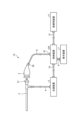
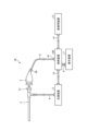
- FIG. 1 is a diagram showing a schematic configuration of an endoscope system according to a first embodiment.
- the endoscope system 1 shown in FIG. 1 is used in the medical field and is a system for observing and treating biological tissue in a subject such as a living body.
- a rigid endoscope system using a rigid endoscope (insertion unit 2) shown in FIG. 1 is described as the endoscope system 1, but the present invention is not limited to this, and may be an endoscope system equipped with a flexible endoscope, for example.
- the endoscope system 1 may be applied to a medical microscope or a medical surgery robot system that includes a medical imaging device that images a subject and performs surgery or processing while displaying an observation image based on an imaging signal (image data) captured by the medical imaging device on a display device.
- a medical imaging device that images a subject and performs surgery or processing while displaying an observation image based on an imaging signal (image data) captured by the medical imaging device on a display device.
- minimally invasive treatments using endoscopes and laparoscopes have become widely used in the medical field.
- minimally invasive treatments using endoscopes and laparoscopes include endoscopic submucosal dissection (ESD), laparoscopy and endoscopic cooperative surgery (LECS), non-exposed endoscopic wall-inversion surgery (NEWS), and transurethral resection of the bladder tumor (TUR-bt).
- a surgeon when a procedure is performed, for example, to mark the area to be operated on as a pre-treatment, a surgeon such as a doctor uses an energy device treatment tool that emits high frequency, ultrasound, microwave, or other energy to perform a marking treatment using cauterization or heat treatment on the area of interest (pathogenic area) that has a lesion on the biological tissue.
- the surgeon also uses an energy device or the like to perform treatments such as ablation and coagulation of the subject's biological tissue.
- the endoscope system 1 shown in FIG. 1 is used when performing surgery or treatment on a subject using a treatment tool (not shown) such as an energy device capable of thermal treatment.
- a treatment tool such as an energy device capable of thermal treatment.
- the endoscope system 1 shown in FIG. 1 is used in transurethral resection of bladder tumor (TUR-Bt) and is used when treating bladder tumors (bladder cancer) and pathogenic areas.
- the endoscope system 1 shown in FIG. 1 includes an insertion section 2, a light source device 3, a light guide 4, an endoscope camera head 5 (an endoscopic imaging device), a first transmission cable 6, a display device 7, a second transmission cable 8, a control device 9, and a third transmission cable 10.
- the insertion section 2 is hard or at least partially soft and has an elongated shape.
- the insertion section 2 is inserted into a subject such as a patient via a trocar.
- the insertion section 2 is provided with an optical system such as a lens that forms an observation image inside.
- the light source device 3 is connected to one end of the light guide 4, and under the control of the control device 9, supplies illumination light to one end of the light guide 4 to be irradiated into the subject.
- the light source device 3 is realized using one or more light sources, such as an LED (Light Emitting Diode) light source, a xenon lamp, or a semiconductor laser element such as an LD (laser diode), a processor which is a processing device having hardware such as an FPGA (Field Programmable Gate Array) or a CPU (Central Processing Unit), and a memory which is a temporary storage area used by the processor.
- the light source device 3 and the control device 9 may be configured to communicate individually as shown in FIG. 1, or may be integrated.
- One end of the light guide 4 is detachably connected to the light source device 3, and the other end is detachably connected to the insertion section 2.
- the light guide 4 guides the illumination light supplied from the light source device 3 from one end to the other, and supplies it to the insertion section 2.
- the endoscopic camera head 5 is detachably connected to the eyepiece 21 of the insertion section 2. Under the control of the control device 9, the endoscopic camera head 5 receives the observation image formed by the insertion section 2 and performs photoelectric conversion to generate an imaging signal (RAW data), and outputs this imaging signal to the control device 9 via the first transmission cable 6.
- RAW data an imaging signal
- the first transmission cable 6 transmits the imaging signal output from the endoscopic camera head 5 to the control device 9, and also transmits setting data, power, etc. output from the control device 9 to the endoscopic camera head 5.
- the setting data refers to a control signal, synchronization signal, clock signal, etc. that controls the endoscopic camera head 5.
- the display device 7 displays an observation image based on an imaging signal that has been subjected to image processing in the control device 9, and various information related to the endoscope system 1.
- the display device 7 is realized using a display monitor such as a liquid crystal or organic EL (Electro Luminescence) display.
- the second transmission cable 8 transmits the image signal that has been subjected to image processing in the control device 9 to the display device 7.
- the control device 9 is realized using a processor, which is a processing device having hardware such as a GPU (Graphics Processing Unit), FPGA, or CPU, and a memory, which is a temporary storage area used by the processor.
- the control device 9 comprehensively controls the operation of the light source device 3, the endoscopic camera head 5, and the display device 7 via each of the first transmission cable 6, the second transmission cable 8, and the third transmission cable 10 according to a program recorded in the memory.
- the control device 9 also performs various image processing on the imaging signal input via the first transmission cable 6 and outputs the result to the second transmission cable 8.
- the third transmission cable 10 has one end detachably connected to the light source device 3 and the other end detachably connected to the control device 9.
- the third transmission cable 10 transmits control data from the control device 9 to the light source device 3.
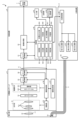
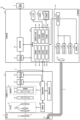
- Fig. 2 is a block diagram showing the functional configuration of the main parts of the endoscope system 1.
- the insertion portion 2 has an optical system 22 and an illumination optical system 23.
- the optical system 22 forms an image of the subject by collecting light such as reflected light from the subject, return light from the subject, excitation light from the subject, and fluorescence emitted from a thermally denatured region that has been thermally denatured by a thermal treatment such as an energy device.
- the optical system 22 is realized using one or more lenses, etc.
- the illumination optical system 23 irradiates the subject with illumination light supplied from the light guide 4.
- the illumination optical system 23 is realized using one or more lenses, etc.
- the light source device 3 includes a condenser lens 30, a first light source unit 31, a second light source unit 32, a third light source unit 33, and a light source control unit .
- the focusing lens 30 focuses the light emitted by each of the first light source unit 31, the second light source unit 32, and the third light source unit 33, and emits the light to the light guide 4.
- the first light source unit 31 emits visible white light (normal light) under the control of the light source control unit 34, thereby supplying white light as illumination light to the light guide 4.
- the first light source unit 31 is configured using a collimator lens, a white LED lamp, a driving driver, etc.
- the first light source unit 31 may supply visible white light by simultaneously emitting light using a red LED lamp, a green LED lamp, and a blue LED lamp.
- the first light source unit 31 may also be configured using a halogen lamp, a xenon lamp, etc.
- the second light source unit 32 emits first narrowband light having a predetermined wavelength band under the control of the light source control unit 34, thereby supplying the first narrowband light as illumination light to the light guide 4.
- the first narrowband light has a wavelength band of 530 nm to 550 nm (with a central wavelength of 540 nm).
- the second light source unit 32 is configured using a green LED lamp, a collimating lens, a transmission filter that transmits light of 530 nm to 550 nm, a driver, etc.
- the third light source unit 33 under the control of the light source control unit 34, emits second narrowband light of a wavelength band different from the first narrowband light, thereby supplying the second narrowband light as illumination light to the light guide 4.
- the second narrowband light has a wavelength band of 400 nm to 430 nm (center wavelength 415 nm).
- the third light source unit 33 is realized using a collimating lens, a semiconductor laser such as a violet LD (laser diode), a driving driver, etc.
- the second narrowband light functions as excitation light that excites advanced glycation endproducts generated by applying heat treatment to biological tissue.
- the light source control unit 34 is realized using a processor, which is a processing device having hardware such as an FPGA or a CPU, and a memory, which is a temporary storage area used by the processor.
- the light source control unit 34 controls the light emission timing and light emission time of each of the first light source unit 31, the second light source unit 32, and the third light source unit 33 based on control data input from the control device 9.
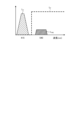
- Fig. 3 is a diagram showing a schematic diagram of the wavelength characteristics of the light emitted by each of the second light source unit 32 and the third light source unit 33.
- the horizontal axis indicates the wavelength (nm), and the vertical axis indicates the wavelength characteristics.
- the broken line L NG indicates the wavelength characteristics of the first narrowband light emitted by the second light source unit 32
- the broken line L V indicates the wavelength characteristics of the second narrowband light (excitation light) emitted by the third light source unit 33.
- the curve L B indicates the blue wavelength band
- the curve L G indicates the green wavelength band
- the curve L R indicates the red wavelength band.
- the second light source unit 32 emits narrowband light having a center wavelength (peak wavelength) of 540 nm and a wavelength band of 530 nm to 550 nm
- the third light source unit 33 emits excitation light having a center wavelength (peak wavelength) of 415 nm and a wavelength band of 400 nm to 430 nm.
- the second light source unit 32 and the third light source unit 33 each emit a first narrowband light and a second narrowband light (excitation light) of mutually different wavelength bands.
- the first narrowband light is used for layer discrimination in biological tissue. Specifically, the first narrowband light increases the difference between the absorbance of the mucosal layer, which is the subject, and the absorbance of the muscle layer, which is the subject, to a degree that makes it possible to distinguish the two subjects. For this reason, in the second image for layer discrimination acquired by irradiating the first narrowband light for layer discrimination, the area in which the mucosal layer is imaged has a smaller pixel value (brightness value) and is darker than the area in which the muscle layer is imaged. That is, in the first embodiment, by using the second image for layer discrimination to generate a display image, it is possible to achieve a display mode in which the mucosal layer and the muscle layer can be easily distinguished.
- the second narrowband light is light for layer discrimination in biological tissue that is different from the first narrowband light.
- the second narrowband light increases the difference in absorbance between the muscle layer, which is the subject, and the fat layer, which is the subject, to a degree that makes it possible to distinguish between the two subjects. Therefore, in the second light image for layer discrimination obtained by irradiating the second narrowband light for layer discrimination, the area in which the muscle layer is imaged has a smaller pixel value (brightness value) and is darker than the area in which the fat layer is imaged. In other words, by using the second image for layer discrimination to generate a display image, it becomes possible to easily distinguish between the muscle layer and the fat layer.
- Both the mucosal layer (biological mucosa) and the muscular layer are subjects that contain a large amount of myoglobin.
- the concentration of myoglobin contained is relatively high in the mucosal layer and relatively low in the muscular layer.
- the difference in the absorption characteristics between the mucosal layer and the muscular layer is caused by the difference in the concentration of myoglobin contained in each of the mucosal layer (biological mucosa) and the muscular layer.
- the difference in absorbance between the mucosal layer and the muscular layer is greatest near the wavelength at which the absorbance of the biological mucosa is at its maximum.
- the first narrowband light for layer discrimination is light that shows a greater difference between the mucosal layer and the muscular layer than light that has a peak wavelength in another wavelength band.
- the second narrowband light for layer discrimination has a lower absorbance of fat compared to the absorbance of the muscle layer
- the pixel value (brightness value) of the area in which the muscle layer is imaged is smaller than the pixel value (brightness value) of the area in which the fat layer is imaged.
- the second narrowband light for layer discrimination is light that corresponds to a wavelength at which the absorbance of the muscle layer is at its maximum, and therefore becomes light that greatly reveals the difference between the muscle layer and the fat layer.
- the difference between the pixel value (brightness value) of the muscle layer area and the pixel value (brightness value) of the fat layer area in the second image for layer discrimination becomes large enough to be distinguished.
- the light source device 3 irradiates the biological tissue with each of the first narrowband light and the second narrowband light.
- the endoscopic camera head 5 which will be described later, can obtain an image in which the mucosal layer, muscle layer, and fat layer that make up the biological tissue can be identified by capturing the light returned from the biological tissue.
- the light that is the combination of the first narrowband light and the second narrowband light will be referred to as special light.
- the second narrowband light excites advanced glycation end products that are generated by subjecting biological tissue to heat treatment by an energy device or the like.
- a glycation reaction Maillard reaction
- the end products resulting from this Maillard reaction are generally called advanced glycation end products (AGEs).
- AGEs are characterized by the inclusion of substances with fluorescent properties.
- biological tissue is heat-treated with an energy device, AGEs are generated by heating amino acids and reducing sugars in the biological tissue and causing a Maillard reaction. The AGEs generated by this heating can be visualized in the state of the heat treatment by fluorescent observation.
- AGEs emit stronger fluorescence than the autofluorescent substances that are originally present in biological tissue.
- the fluorescent properties of AGEs generated in biological tissue by heat treatment by an energy device or the like are utilized to visualize the thermally denatured area caused by the heat treatment.
- the second light source unit 32 excitation light
- the biological tissue with blue excitation light with a wavelength of about 415 nm in order to excite AGEs.
- a fluorescent image (thermal denaturation image) can be observed based on an imaging signal that captures the fluorescence (e.g., green light with a wavelength of 490 to 625 nm) emitted from the thermal denaturation region generated by AGEs.
- an imaging signal that captures the fluorescence (e.g., green light with a wavelength of 490 to 625 nm) emitted from the thermal denaturation region generated by AGEs.
- the second narrowband light alone will be referred to as excitation light.
- the endoscopic camera head 5 includes an optical system 51, a drive unit 52, an image sensor 53, a cut filter 54, an A/D conversion unit 55, a P/S conversion unit 56, an image capture recording unit 57, and an image capture control unit 58.
- the optical system 51 forms an image of the subject collected by the optical system 22 of the insertion part 2 on the light receiving surface of the image sensor 53.
- the optical system 51 is capable of changing the focal length and focal position.
- the optical system 51 is configured using a plurality of lenses 511.
- the optical system 51 changes the focal length and focal position by moving each of the plurality of lenses 511 on the optical axis L1 using the drive part 52.
- the driving unit 52 moves the multiple lenses 511 of the optical system 51 along the optical axis L1 under the control of the imaging control unit 58.
- the driving unit 52 is configured using a motor such as a stepping motor, a DC motor, or a voice coil motor, and a transmission mechanism such as a gear that transmits the rotation of the motor to the optical system 51.
- the imaging element 53 is realized by using a CCD (Charge Coupled Device) or CMOS (Complementary Metal Oxide Semiconductor) image sensor having multiple pixels arranged in a two-dimensional matrix. Under the control of the imaging control unit 58, the imaging element 53 receives the subject image (light rays) formed by the optical system 51 through the cut filter 54, performs photoelectric conversion to generate an imaging signal (RAW data), and outputs it to the A/D conversion unit 55.
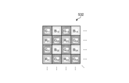
- the imaging element 53 has a pixel unit 531 and a color filter 532.
- Fig. 4 is a diagram showing a schematic configuration of the pixel unit 531.
- the imaging control unit 58 the pixel unit 531 reads out image signals as image data from pixels Pnm in a readout region arbitrarily set as a readout target among the plurality of pixels Pnm , and outputs the image signals to the A/D conversion unit 55.
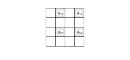
- FIG. 5 is a diagram showing a schematic configuration of color filter 532.
- color filter 532 is configured in a Bayer array with 2 ⁇ 2 as one unit.
- Color filter 532 is configured using a filter R that transmits light in the red wavelength band, two filters G that transmit light in the green wavelength band, and a filter B that transmits light in the blue wavelength band.
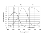
- Fig. 6 is a diagram showing the sensitivity and wavelength band of each filter.
- the horizontal axis indicates wavelength (nm) and the vertical axis indicates transmission characteristics (sensitivity characteristics).
- the curve L- B indicates the transmission characteristics of filter B
- the curve L- G indicates the transmission characteristics of filter G
- the curve L- R indicates the transmission characteristics of filter R.
- the filter B transmits light in the blue wavelength band.
- the filter G transmits light in the green wavelength band.
- the filter R transmits light in the red wavelength band.
- the pixel P- nm having the filter R disposed on the light receiving surface is referred to as the R pixel
- the pixel P -nm having the filter G disposed on the light receiving surface is referred to as the G pixel
- the pixel P -nm having the filter B disposed on the light receiving surface is referred to as the B pixel.
- the image sensor 53 configured in this manner receives the subject image formed by the optical system 51, it generates color signals (R signal, G signal, and B signal) for the R pixel, G pixel, and B pixel, respectively, as shown in Figures 7A to 7C.
- the cut filter 54 is disposed on the optical axis L1 between the optical system 51 and the image sensor 53.
- the cut filter 54 is provided on the light receiving surface side (incident surface side) of the G pixel provided with the filter G that transmits at least the green wavelength band of the color filter 532.
- the cut filter 54 blocks light in a short wavelength band including the wavelength band of the excitation light and transmits a wavelength band longer than the wavelength band of the excitation light.
- Fig. 8 is a diagram showing a schematic configuration of the cut filter 54. As shown in Fig. 8, the filter F11 constituting the cut filter 54 is disposed at the position where the filter G11 (see Fig. 5) is disposed, on the light receiving surface side directly above the filter G11 .
- FIG. 9 and 10 are diagrams showing the transmission characteristics of the cut filter 54.
- the horizontal axis indicates wavelength (nm) and the vertical axis indicates the transmission characteristics.
- the broken line L- F indicates the transmission characteristics of the cut filter 54
- the broken line L- NG indicates the wavelength characteristics of the first narrowband light
- the broken line L- V indicates the wavelength characteristics of the second narrowband light (excitation light).
- Fig. 10 shows the transmission characteristics when the excitation light is irradiated onto the thermally denatured region and fluorescence from the thermally denatured region is received.
- the cut filter 54 blocks the wavelength band of the second narrowband light (excitation light) and transmits a wavelength band on the longer wavelength side than the wavelength band of the second narrowband light (excitation light). Specifically, the cut filter 54 blocks light in the wavelength band on the shorter wavelength side of 400 nm to less than 430 nm, which includes the wavelength band of the second narrowband light (excitation light), and transmits light in the wavelength band on the longer wavelength side than 400 nm to 430 nm, which includes the second narrowband light (excitation light). Furthermore, as shown in FIG. 10, the cut filter 54 transmits fluorescence in the wavelength band from the thermally denatured region when excitation light is irradiated to the thermally denatured region.
- the A/D conversion unit 55 under the control of the imaging control unit 58, performs A/D conversion processing on the analog imaging signal input from the imaging element 53 and outputs the result to the P/S conversion unit 56.
- the A/D conversion unit 55 is realized using an A/D conversion circuit or the like.
- the P/S conversion unit 56 performs parallel/serial conversion on the digital imaging signal input from the A/D conversion unit 55 under the control of the imaging control unit 58, and outputs the parallel/serial converted imaging signal to the control device 9 via the first transmission cable 6.
- the P/S conversion unit 56 is realized using a P/S conversion circuit or the like. Note that in the first embodiment, instead of the P/S conversion unit 56, an E/O conversion unit that converts the imaging signal into an optical signal may be provided and the imaging signal may be output to the control device 9 by the optical signal, or the imaging signal may be transmitted to the control device 9 by wireless communication such as Wi-Fi (Wireless Fidelity) (registered trademark).
- Wi-Fi Wireless Fidelity
- the imaging and recording unit 57 records various information related to the endoscopic camera head 5 (e.g., pixel information of the imaging element 53, characteristics of the cut filter 54).
- the imaging and recording unit 57 also records various setting data and control parameters transmitted from the control device 9 via the first transmission cable 6.
- the imaging and recording unit 57 is configured using a non-volatile memory and a volatile memory.
- the imaging control unit 58 controls the operation of each of the drive unit 52, the imaging element 53, the A/D conversion unit 55, and the P/S conversion unit 56 based on the setting data received from the control device 9 via the first transmission cable 6.
- the imaging control unit 58 is realized using a TG (Timing Generator), a processor having hardware such as an ASIC (Application Specific Integrated Circuit) or a CPU, and a memory that is a temporary storage area used by the processor.
- the control device 9 includes an S/P conversion unit 91 , an image processing unit 92 , an input unit 93 , a recording unit 94 , and a control unit 95 .
- the S/P conversion unit 91 Under the control of the control unit 95, the S/P conversion unit 91 performs serial/parallel conversion on the image data received from the endoscopic camera head 5 via the first transmission cable 6 and outputs the converted data to the image processing unit 92. If the endoscopic camera head 5 outputs an imaging signal as an optical signal, the S/P conversion unit 91 may be replaced by an O/E conversion unit that converts the optical signal into an electrical signal. If the endoscopic camera head 5 transmits an imaging signal via wireless communication, the S/P conversion unit 91 may be replaced by a communication module capable of receiving wireless signals.
- the image processing unit 92 Under the control of the control unit 95, the image processing unit 92 performs predetermined image processing on the imaging signal of parallel data input from the S/P conversion unit 91 and outputs the result to the display device 7.
- the predetermined image processing includes demosaic processing, white balance processing, gain adjustment processing, gamma correction processing, and format conversion processing.
- the image processing unit 92 is realized using a processor, which is a processing device having hardware such as a GPU or FPGA, and a memory, which is a temporary storage area used by the processor.
- the image processing unit 92 When the light source device 3 emits special light, the image processing unit 92 performs image processing on the signal values of the G and B pixels contained in the imaging signal input from the endoscopic camera head 5 via the S/P conversion unit 91 to generate a pseudo-color image (narrowband image).
- the signal value of the G pixel contains information on the deep mucosa of the subject.
- the signal value of the B pixel contains information on the surface mucosa of the subject. Therefore, the image processing unit 92 performs image processing such as gain control processing, pixel complementation processing, and mucosa enhancement processing on the signal values of the G and B pixels contained in the imaging signal to generate a pseudo-color image, and outputs this pseudo-color image to the display device 7.
- the pseudo-color image is an image generated using only the signal values of the G and B pixels. Note that the image processing unit 92 acquires the signal values of the R pixels, but does not use them to generate the pseudo-color image and deletes them.
- the image processing unit 92 When the light source device 3 irradiates excitation light, the image processing unit 92 performs image processing on the signal values of the G pixels and B pixels contained in the imaging signal input from the endoscopic camera head 5 via the S/P conversion unit 91 to generate a fluorescent image (pseudo color image).
- the signal value of the G pixel contains fluorescent information emitted from the heat treatment area.
- the B pixel contains background information, which is the biological tissue surrounding the heat treatment area.
- the image processing unit 92 performs image processing such as gain control processing, pixel complement processing, and mucosa enhancement processing on the signal values of the G pixels and B pixels contained in the image data to generate a fluorescent image (pseudo color image), and outputs this fluorescent image (pseudo color image) to the display device 7.
- the image processing unit 92 performs gain control processing to make the gain for the signal value of the G pixel larger than the gain for the signal value of the G pixel during normal light observation, while making the gain for the signal value of the B pixel smaller than the gain for the signal value of the B pixel during normal light observation.
- the image processing unit 92 performs gain control processing so that the signal values of the G pixels and the B pixels are the same (1:1).
- the input unit 93 receives inputs of various operations related to the endoscope system 1 and outputs the received operations to the control unit 95.
- the input unit 93 is configured using a mouse, a foot switch, a keyboard, buttons, switches, a touch panel, etc.
- the recording unit 94 is realized using a recording medium such as a volatile memory, a non-volatile memory, an SSD (Solid State Drive), an HDD (Hard Disk Drive), a memory card, etc.
- the recording unit 94 records data including various parameters necessary for the operation of the endoscope system 1.
- the recording unit 94 also has a program recording unit 941 that records various programs for operating the endoscope system 1.
- the control unit 95 is realized using a processor having hardware such as an FPGA or a CPU, and a memory that is a temporary storage area used by the processor.
- the control unit 95 comprehensively controls each component of the endoscope system 1. Specifically, the control unit 95 reads out a program recorded in the program recording unit 941 into a working area of the memory and executes it, and controls each component through the execution of the program by the processor, thereby enabling the hardware and software to work together to realize a functional module that meets a specific purpose.
- the control unit 95 has an acquisition unit 951, a generation unit 952, a setting unit 953, an identification unit 954, an alignment unit 955, a determination unit 956, an output control unit 957, and a learning unit 958.
- the acquisition unit 951 acquires, via the S/P conversion unit 91 and the image processing unit 92, an image signal of white light generated by the endoscopic camera head 5 when the light source device 3 irradiates the white light toward the biological tissue.
- the acquisition unit 951 also acquires, via the S/P conversion unit 91 and the image processing unit 92, setting information in which a region of interest is set for the biological tissue, and thermal denaturation information related to a thermally denatured region in which thermal denaturation has occurred due to thermal treatment of the biological tissue.
- the acquisition unit 951 acquires a first image as the setting information, and a second image as the thermal denaturation information.
- the first image is a special light image
- the second image is a fluorescent image.
- the generating unit 952 generates a first image based on the first imaging signal acquired by the acquiring unit 951.
- the first image is a special light image.
- the first image is the setting information in the first embodiment.
- the generating unit 952 generates a second image based on the second imaging signal acquired by the acquiring unit 951.
- the second image is a fluorescent image.
- the generating unit 952 generates a white light image based on the white light image signal acquired by the acquiring unit 951.
- the setting unit 953 sets a region of interest based on the feature amount included in the first image generated by the generation unit 952. Specifically, the setting unit 953 determines whether or not the luminance value of each pixel constituting the first image generated by the generation unit 952 is equal to or greater than a predetermined value, and sets a region formed by a plurality of pixels whose luminance values are equal to or greater than the predetermined value as the region of interest.
- the identification unit 954 identifies a thermally altered region based on the second image generated by the generation unit 952. Specifically, the identification unit 954 determines whether or not the brightness value is equal to or greater than a predetermined value for each pixel constituting the second image, and identifies a region formed by multiple pixels having a brightness value equal to or greater than the predetermined value as a thermally altered region.
- the alignment unit 955 performs alignment processing between the first image and the second image. For example, the alignment unit 955 performs alignment processing between the first image and the second image based on the position where the feature amount of each pixel constituting the first image and the feature amount of each pixel constituting the second image match.
- the feature amount is, for example, pixel value, brightness value, edge, contrast, etc.
- the determination unit 956 determines whether or not there is a thermally denatured region outside the region of interest based on the setting information and the thermal denaturation information. Specifically, the determination unit 956 determines whether or not there is a thermally denatured region outside the region of interest based on the setting information of the first image on which the alignment unit 955 has performed the alignment process and the thermal denaturation information of the second image.
- the output control unit 957 When the determination unit 956 determines that there is a thermally altered region outside the region of interest, the output control unit 957 outputs support information to the display device 7 indicating that there is a thermally altered region outside the region of interest. Specifically, the output control unit 957 displays one or more of a message, a figure, and a sound indicating that there is a thermally altered region outside the region of interest by outputting them as support information to the display device 7.
- the output control unit 957 may generate a display image by identifiably superimposing the thermally altered region occurring outside the region of interest identified by the identification unit 954 and the thermally altered region within the region of interest on the white light image generated by the generation unit 952, and output this display image to the display device 7 as support information.
- the output control unit 957 may also generate a display image in which it is possible to distinguish the thermally altered region occurring outside the region of interest identified by the identification unit 954 and the thermally altered region within the region of particular interest, and output this display image to the display device 7 as support information.
- the learning unit 958 uses as input data a fluorescent image generated based on an imaging signal generated by irradiating excitation light on biological tissue to capture light emitted from a thermally denatured region, and a white light image generated based on an imaging signal generated by irradiating white light on biological tissue to capture return light, and generates a trained model by machine learning using teacher data in which support information is output as data indicating that a thermally denatured region included in the fluorescent image is outside the region of interest included in the white light image.
- the learning unit 958 uses as input data a fluorescent image obtained by irradiating excitation light on biological tissue to capture fluorescence, and a special light image (narrowband light observation image) or a white light image obtained by irradiating biological tissue with narrowband light having a wavelength determined according to the absorption rate of hemoglobin, and generates a trained model by machine learning using teacher data in which support information is output as data indicating that a thermally denatured region included in the fluorescent image is outside the region of interest included in the white light image.
- the trained model is composed of a neural network in which each layer has one or more nodes.
- the type of machine learning is not particularly limited, but may be, for example, a method in which teacher data and training data are prepared that correspond to a fluorescent image and a special light image (narrowband light observation image) or a white light image, and annotation information that specifies the position or area of a thermally denatured area located outside the area of interest based on the fluorescent image and the special light image (narrowband light observation image) or the white light image, and the teacher data and training data are input into a computational model based on a multi-layer neural network for learning.
- a technique based on a deep neural network which is a multi-layer neural network such as a convolutional neural network (CNN) or a 3D-CNN
- DNN deep neural network
- CNN convolutional neural network
- 3D-CNN 3D-CNN
- RNN recurrent neural network
- LSTM long short-term memory units
- a control unit of a learning device different from the control device 4 may execute these functions and generate a trained model.
- the function of the learning unit 958 may be provided in the image processing unit 92.
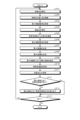
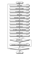
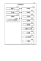
- FIG 11 is a flow chart showing an outline of the process executed by the control device 9.
- control unit 95 controls the light source control unit 34 of the light source device 3 to cause the second light source unit 32 and the third light source unit 33 to emit light and supply special light to the insertion unit 2, thereby irradiating the special light toward the biological tissue (step S101).
- control unit 95 controls the imaging control unit 58 to cause the imaging element 53 to capture the return light of the special light from the biological tissue (step S102).
- the acquisition unit 951 acquires a first imaging signal generated by imaging by the imaging element 53 of the endoscopic camera head 5 (step S103).
- control unit 95 controls the light source control unit 34 of the light source device 3 to cause the third light source unit 33 to emit light and irradiate excitation light (step S104).
- control unit 95 controls the imaging control unit 58 to cause the imaging element 53 to capture an image of the fluorescence from the thermally denatured region of the biological tissue (step S105).
- the acquisition unit 951 acquires a second imaging signal generated by the imaging element 53 of the endoscopic camera head 5 capturing an image (step S106).
- the generating unit 952 generates a first image based on the first imaging signal acquired by the acquiring unit 951 (step S107).
- the first image is a special light image.
- the first image is the setting information in the first embodiment.
- the generating unit 952 generates a second image based on the second imaging signal acquired by the acquiring unit 951 (step S108).
- the second image is a fluorescent image.
- the setting unit 953 sets the region of interest based on the features contained in the first image (step S109).
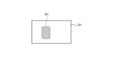
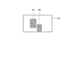
- FIG. 12 is a schematic diagram showing the region of interest set by the setting unit 953 for the first image.
- the setting unit 953 sets the region of interest based on features contained in the first image. Specifically, the setting unit 953 determines whether the luminance value of each pixel constituting the first image P1 is equal to or greater than a predetermined value, and sets the region formed by multiple pixels having luminance values equal to or greater than the predetermined value as the region of interest D1.
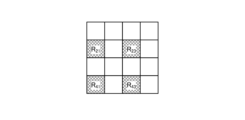
- the identification unit 954 identifies the thermally altered region based on the second image (step S110).
- the identifying unit 954 identifies the thermally altered region based on the second image. Specifically, the identifying unit 954 determines whether the brightness value is equal to or greater than a predetermined value for each pixel constituting the second image P2, and identifies the region formed by a plurality of pixels having a brightness value equal to or greater than the predetermined value as the thermally altered region R1, R2.
- the identifying unit 954 may identify the thermally altered region (fluorescent region) generated by the thermal treatment by comparing a reference image based on an image signal generated by the image sensor 53 of the endoscopic camera head 5 by imaging before the thermal treatment with a resection treatment tool or the like with a fluorescent image, which is the second image.
- the reference image may be recorded in advance in the recording unit 94.
- the alignment unit 955 performs alignment processing between the first image and the second image (step S111).
- FIG. 14 is a schematic diagram showing the alignment process of the alignment unit 955.
- the alignment unit 955 uses well-known techniques to perform alignment process so that the positions of feature amounts contained in the first image P1 and the positions of feature amounts contained in the second image P2 match.
- the alignment unit 955 performs alignment process of the first image P1 and the second image P2 based on the positions where the feature amounts of each pixel constituting the first image P1 and the feature amounts of each pixel constituting the second image P2 match.
- feature amounts are, for example, pixel values, brightness values, edges, contrast, etc.
- the determination unit 956 determines whether or not there is a thermally altered region outside the region of interest based on the setting information of the first image on which the alignment unit 955 has performed the alignment process and the thermally altered information of the second image (step S112). In the case shown in FIG. 13, the determination unit 956 determines that there is a thermally altered region R2 outside the region of interest D1 based on the region of interest D1 of the first image P1 on which the alignment unit 955 has performed the alignment process and the thermally altered regions R1, R2 of the second image P2. In the case shown in FIG. 13, the determination unit 956 determines that there is a thermally altered region R2 outside the region of interest D1.
- step S112 determines that there is a thermally altered region outside the region of interest. If the determination unit 956 determines that there is a thermally altered region outside the region of interest (step S112: Yes), the control device 9 proceeds to step S113 described later. On the other hand, if the determination unit 956 determines that there is no thermally altered region outside the region of interest (step S112: No), the control device 9 proceeds to step S114, which will be described later.
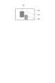
- step S113 the output control unit 957 outputs support information to the display device 7 that there is a thermally denatured region outside the region of interest.
- the output control unit 957 generates a display image in which information that there is a thermally denatured region R2 outside the region of interest D1 is superimposed on the first image P1, and displays the display image by outputting the display image as support information to the display device 7.
- the output control unit 957 may display a display image (see, for example, FIG.
- the output control unit 957 may generate a display image in which one or more of a message and a figure that there is a thermally denatured region outside the region of interest are superimposed on the first image, and displays the display image by outputting the display image to the display device 7. This allows the user to understand that there is a thermally denatured region outside the region of interest.
- the output control unit 957 may also output a message or graphic to the display device 7 to display the message or graphic, etc., simply indicating that there is a thermally altered region other than the region of interest.
- the control unit 95 determines whether or not an end signal to end the observation of the subject by the endoscope system 1 has been input from the input unit 93 (step S114). If the control unit 95 determines that an end signal to end the observation of the subject by the endoscope system 1 has been input from the input unit 93 (step S114: Yes), the control device 9 ends this process. On the other hand, if the control unit 95 determines that an end signal to end the observation of the subject by the endoscope system 1 has not been input from the input unit 93 (step S114: No), the control device 9 returns to step S101 described above.
- the output control unit 957 when the determination unit 956 determines that there is a thermally altered region outside the region of interest, the output control unit 957 outputs to the display device 7 a message indicating that there is a thermally altered region outside the region of interest, so that it is possible to grasp the presence or absence of a thermally altered region outside the region of interest.
- the setting unit 953 sets the region of interest based on the feature amount contained in the first image, so that it is possible to provide assistance to the user during the treatment.
- the identification unit 954 identifies the thermally altered region based on the second image, so that the thermally altered region can be easily identified.
- the learning unit 958 is provided in the control device 4, but this is not limited thereto, and the learning unit 958 that generates a trained model may be provided in a device different from the control device 4, such as a learning device or a server that can be connected via a network.
- the output control unit 957 may generate a display image by identifiably superimposing the thermally altered area occurring outside the region of interest identified by the identification unit 954 and the thermally altered area within the region of interest on the white light image generated by the generation unit 952, and output this display image to the display device 7 as support information. This allows the user to recognize the thermally altered area outside the region of interest on the white light image.
- the output control unit 957 may generate a display image that allows a distinction between a thermally altered region occurring outside the region of interest identified by the identification unit 954 and a thermally altered region within the region of particular interest, and output this display image to the display device 7 as support information. This allows the user to easily distinguish between a thermally altered region occurring outside the region of interest and a thermally altered region within the region of particular interest.
- the endoscope system according to the second embodiment has the same configuration as the endoscope system 1 according to the first embodiment described above, but the process executed by the control device 9 is different. Specifically, in the first embodiment described above, the region of interest is set according to the feature amount of the special light image serving as the first image, but in the second embodiment, the first image is a white light image, and the region of interest is set according to an instruction signal input from the input unit 93. For this reason, the process executed by the control device 9 included in the endoscope system 1 according to the second embodiment will be described below.
- Fig. 15 is a flowchart showing an outline of the process executed by the control device 9 according to the second embodiment.
- the control device 9 executes steps S101A, S102A, S107A, and S109A instead of steps S101, S102, S107, and S109 described above in Fig. 11, and otherwise executes the same processes as those in Fig. 11 described above. Therefore, in Fig. 15, steps S101A, S102A, S107A, and S109A will be described.
- control unit 95 controls the light source control unit 34 of the light source device 3 to cause the first light source unit 31 to emit light and supply white light to the insertion unit 2, thereby irradiating the white light toward the biological tissue (step S101A).
- control unit 95 controls the imaging control unit 58 to cause the imaging element 53 to capture the white light returning from the biological tissue (step S102A).
- the acquisition unit 951 acquires a first image signal generated by the imaging element 53 of the endoscopic camera head 5 capturing an image (step S103A).
- the acquisition unit 951 acquires, as setting information, instruction information indicating an annotation input by the user via the input unit 93 for the white light image displayed by the display device 7.
- the control device 9 proceeds to step S104.
- step S107A the generating unit 952 generates a first image based on the first imaging signal acquired by the acquiring unit 951.
- the first image is a white light image.
- step S109A the setting unit 953 sets a region of interest in the white light image displayed on the display device 7 in response to an instruction signal acquired by the acquisition unit 951, instructing the user to specify an annotation via the input unit 93.
- the setting unit 953 sets an instruction signal corresponding to an area designated by the user by operating the input unit 93 as the region of interest for annotation.
- the second embodiment described above has the same effect as the first embodiment, that is, it is possible to grasp the presence or absence of a thermally altered area outside the area of interest.
- the setting unit 953 sets the region of interest based on the feature amount included in the first image, but in the third embodiment, a medical device different from the control device detects the region of interest and sets the region of interest based on the detection result. For this reason, an endoscope system according to the third embodiment will be described below. Note that the same components as those in the endoscope system 1 according to the first embodiment described above are denoted by the same reference numerals and detailed description thereof will be omitted.
- FIG. 16 is a diagram showing a schematic configuration of an endoscope system according to embodiment 3.
- An endoscope system 1A shown in Fig. 16 further includes a medical device 11 and a fourth transmission cable 12 in addition to the configuration of the endoscope system 1 according to embodiment 1 described above.
- the medical device 11 is realized using a processor, which is a processing device having hardware such as a GPU, FPGA, or CPU, and a memory, which is a temporary storage area used by the processor.
- the medical device 11 acquires various information from the control device 9 via the fourth transmission cable 12, and outputs the acquired various information to the control device 9.
- the medical device 11 also performs machine learning using teacher data that associates multiple images with annotation information that includes a region of interest included in each of the multiple images, and outputs position information to the control device 9 for setting the region of interest using a learning model that uses a white light image as input data and outputs the position of the region of interest in the white light image as output data.
- the machine learning is deep learning, etc.
- the fourth transmission cable 12 has one end detachably connected to the control device 9 and the other end detachably connected to the medical device 11.
- the fourth transmission cable 12 transmits various information from the control device 9 to the medical device 11 and transmits various information from the medical device 11 to the control device 9.
- Fig. 17 is a flowchart showing an outline of the processing executed by the control device 9.
- the control device 9 executes step S109B instead of step S109A described above in Fig. 15, and otherwise executes the same processing as the processing in Fig. 15 described above. For this reason, step S109B will be described in Fig. 17.
- step S109B the setting unit 953 sets the region of interest in the white light image based on the position information for setting the region of interest input from the medical device 11 acquired by the acquisition unit 951. For example, the setting unit 953 sets the region of interest in the white light image based on the position information for setting a region of a tumor or the like included in the white light image as the region of interest using a learning model provided in the medical device 11.
- step S109B the control device 9 proceeds to step S110.
- the third embodiment described above has the same effect as the first embodiment, that is, it is possible to grasp the presence or absence of a thermally altered area outside the area of interest.
- the control device 9 determines whether or not there is a thermally altered region outside the region of interest.
- a separate medical device is provided that determines whether or not there is a thermally altered region outside the region of interest and outputs the determination result.
- the configuration of an endoscope system according to the fourth embodiment will be described below. Note that the same components as those in the endoscope system 1 according to the first embodiment described above are given the same reference numerals and detailed description will be omitted.
- FIG. 18 is a diagram showing a schematic configuration of an endoscope system according to embodiment 4.
- An endoscope system 1B shown in Fig. 18 includes a control device 9B instead of the control device 9 according to the above-described embodiment 1.
- the endoscope system 1B further includes a medical device 13 and a fifth transmission cable 14 in addition to the configuration of the endoscope system 1 according to the above-described embodiment 1.
- the control device 9B is realized using a processor, which is a processing device having hardware such as a GPU, FPGA, or CPU, and a memory, which is a temporary storage area used by the processor.
- the control device 9B comprehensively controls the operations of the light source device 3, the endoscopic camera head 5, the display device 7, and the medical device 13 via each of the first transmission cable 6, the second transmission cable 8, the third transmission cable 10, and the fifth transmission cable 14 according to the program recorded in the memory.
- the control device 9B omits the functions of the acquisition unit 951, the generation unit 952, the setting unit 953, the identification unit 954, the alignment unit 955, the determination unit 956, the output control unit 957, and the learning unit 958 from the control unit 95 according to the above-mentioned first embodiment.
- the medical device 13 is realized using a processor, which is a processing device having hardware such as a GPU, FPGA, or CPU, and a memory, which is a temporary storage area used by the processor.
- the medical device 13 acquires various information from the control device 9B via the fifth transmission cable 14, and outputs the acquired various information to the control device 9B.
- the detailed functional configuration of the medical device 13 will be described later.
- the fifth transmission cable 14 has one end detachably connected to the control device 9B and the other end detachably connected to the medical device 13.
- the fifth transmission cable 14 transmits various information from the control device 9B to the medical device 13 and transmits various information from the medical device 13 to the control device 9B.
- Fig. 19 is a block diagram showing the functional configuration of the medical device 13. As shown in Fig. 19, the medical device 13 includes a communication I/F 131, an input unit 132, a recording unit 133, and a control unit 134.
- the communication I/F 131 is an interface for communicating with the control device 9B via the fifth transmission cable 14.
- the communication I/F 131 receives various information from the control device 9A according to a predetermined communication standard, and outputs the received information to the control unit 134.
- the input unit 132 receives inputs of various operations related to the endoscope system 1B and outputs the received operations to the control unit 134.
- the input unit 132 is configured using a mouse, a foot switch, a keyboard, buttons, switches, a touch panel, etc.
- the recording unit 133 is realized using a recording medium such as a volatile memory, a non-volatile memory, an SSD, an HDD, or a memory card.
- the recording unit 133 records data including various parameters necessary for the operation of the medical device 13.
- the recording unit 133 also has a program recording unit 133a that records various programs for operating the medical device 13.
- the control unit 134 is realized using a processor having hardware such as an FPGA or a CPU, and a memory that is a temporary storage area used by the processor.
- the control unit 134 comprehensively controls each unit that constitutes the medical device 13.
- the control unit 134 has the same functions as the control unit 95 according to the above-mentioned first embodiment. Specifically, the control unit 134 has an acquisition unit 951, a generation unit 952, a setting unit 953, an identification unit 954, an alignment unit 955, a determination unit 956, an output control unit 957, and a learning unit 958.
- the medical device 13 configured in this manner executes the same processing as the control device 9 according to the first embodiment described above, and outputs the processing results to the control device 9B.
- the control device 9B outputs information according to the presence or absence of a thermally altered region outside the region of interest, which is the processing result of the medical device 13, to the display device 7.
- the fourth embodiment described above has the same effect as the first embodiment, that is, it is possible to grasp the presence or absence of a thermally altered area outside the area of interest.
- the output control unit 957 outputs the result of the determination of the presence or absence of a thermally altered region outside the region of interest determined by the determination unit 956 to the display device 7, but in the fifth embodiment, the light source device irradiates the thermally altered region outside the region of interest toward the biological tissue.
- the functional configuration of the main parts of the endoscope system according to the fifth embodiment will be described. Note that, in the following, the same components as those in the endoscope system 1 according to the first embodiment described above are denoted by the same reference numerals, and detailed description thereof will be omitted.
- Fig. 20 is a diagram illustrating a functional configuration of a main part of an endoscope system 1C according to embodiment 4.
- the endoscope system 1C shown in Fig. 20 includes a light source device 3C instead of the light source device 3 of the endoscope system 1 according to embodiment 1 described above.
- the light source device 3C further includes a projection unit 35 that projects information relating to the region of interest and the thermally altered region outside the region of interest onto the biological tissue.
- the projection unit 35 projects support information, including information on the region of interest input from the control device 9 and information on the thermally altered region outside the region of interest, onto the biological tissue via the condenser lens 30 and the light guide 4.
- the projection unit 35 identifiably projects information indicating that the region is a region of interest and information indicating that the region is a thermally altered region outside the region of interest as support information onto each of the regions of biological tissue corresponding to the region of interest and the region of biological tissue corresponding to the thermally altered region outside the region of interest.
- the projection unit 35 projects blue and green onto each of the regions of biological tissue corresponding to the region of interest and the region of biological tissue corresponding to the thermally altered region outside the region of interest.
- the projection unit 35 functions as a projection device.
- the fifth embodiment described above has the same effect as the first embodiment, that is, it is possible to grasp the presence or absence of a thermally altered area outside the area of interest.
- Various inventions can be formed by appropriately combining multiple components disclosed in the endoscope systems according to the above-mentioned embodiments 1 to 5 of the present disclosure. For example, some components may be deleted from all the components described in the endoscope systems according to the above-mentioned embodiments of the present disclosure. Furthermore, the components described in the endoscope systems according to the above-mentioned embodiments of the present disclosure may be appropriately combined.
- the systems are connected to each other by wires, but they may be connected wirelessly via a network.
- the functions of the control unit provided in the endoscope system, and the functional modules of the acquisition unit 951, generation unit 952, setting unit 953, identification unit 954, alignment unit 955, determination unit 956, and output control unit 957 may be provided in a server or the like that can be connected via a network.
- a server may be provided for each functional module.
- transurethral bladder tumor resection an example of use in transurethral bladder tumor resection has been described, but the present invention is not limited to this, and can be applied to various procedures, such as resecting lesions using an energy device, etc.
- the "unit" described above can be read as a “means” or a “circuit.”
- a control unit can be read as a control means or a control circuit.
Landscapes
- Health & Medical Sciences (AREA)
- Life Sciences & Earth Sciences (AREA)
- Engineering & Computer Science (AREA)
- Surgery (AREA)
- Medical Informatics (AREA)
- General Health & Medical Sciences (AREA)
- Public Health (AREA)
- Nuclear Medicine, Radiotherapy & Molecular Imaging (AREA)
- Radiology & Medical Imaging (AREA)
- Physics & Mathematics (AREA)
- Biomedical Technology (AREA)
- Pathology (AREA)
- Heart & Thoracic Surgery (AREA)
- Optics & Photonics (AREA)
- Biophysics (AREA)
- Molecular Biology (AREA)
- Animal Behavior & Ethology (AREA)
- Veterinary Medicine (AREA)
- Signal Processing (AREA)
- Primary Health Care (AREA)
- Epidemiology (AREA)
- Evolutionary Computation (AREA)
- Artificial Intelligence (AREA)
- Data Mining & Analysis (AREA)
- Quality & Reliability (AREA)
- Computer Vision & Pattern Recognition (AREA)
- General Physics & Mathematics (AREA)
- Theoretical Computer Science (AREA)
- Databases & Information Systems (AREA)
- Endoscopes (AREA)
Abstract
Description
〔内視鏡システムの構成〕
図1は、実施の形態1に係る内視鏡システムの概略構成を示す図である。図1に示す内視鏡システム1は、医療分野に用いられ、生体等の被検体内の生体組織を観察および処置するシステムである。なお、実施の形態1では、内視鏡システム1として、図1に示す硬性鏡(挿入部2)を用いた硬性内視鏡システムについて説明するが、これに限定されることなく、例えば軟性の内視鏡を備えた内視鏡システムであってもよい。さらに、内視鏡システム1として、被検体を撮像する医療用撮像装置を備え、この医療用撮像装置によって撮像された撮像信号(画像データ)に基づく観察画像を表示装置に表示させながら手術や処理等を行う医療用顕微鏡または医療用手術ロボットシステム等のものであっても適用することができる。
次に、上述した内視鏡システム1の要部の機能構成について説明する。図2は、内視鏡システム1の要部の機能構成を示すブロック図である。
まず、挿入部2の構成について説明する。挿入部2は、光学系22と、照明光学系23と、を有する。
次に、光源装置3の構成について説明する。光源装置3は、集光レンズ30と、第1の光源部31と、第2の光源部32と、第3の光源部33と、光源制御部34と、を備える。
図2に戻り、内視鏡システム1の構成の説明を続ける。
次に、内視鏡カメラヘッド5の構成について説明する。内視鏡カメラヘッド5は、光学系51と、駆動部52と、撮像素子53と、カットフィルタ54と、A/D変換部55と、P/S変換部56と、撮像記録部57と、撮像制御部58と、を備える。
カットフィルタ54は、光学系51と撮像素子53との光軸L1上に配置される。カットフィルタ54は、少なくともカラーフィルタ532の緑色の波長帯域を透過するフィルタGが設けられたG画素の受光面側(入射面側)に設けられる。カットフィルタ54は、励起光の波長帯域を含む短波長の波長帯域の光を遮光し、励起光の波長帯域より長波長側の波長帯域を透過する。
A/D変換部55は、撮像制御部58による制御のもと、撮像素子53から入力されたアナログの撮像信号に対してA/D変換処理を行ってP/S変換部56へ出力する。A/D変換部55は、A/D変換回路等を用いて実現される。
次に、制御装置9の構成について説明する。
制御装置9は、S/P変換部91と、画像処理部92と、入力部93と、記録部94と、制御部95と、を備える。
次に、制御装置9が実行する処理について説明する。図11は、制御装置9が実行する処理の概要を示すフローチャートである。
次に、実施の形態2について説明する。実施の形態2に係る内視鏡システムは、上述した実施の形態1に係る内視鏡システム1と同一の構成を有し、制御装置9が実行する処理が異なる。具体的には、上述した実施の形態1では、第1の画像としての特殊光画像の特徴量に応じて関心領域を設定していたが、実施の形態2では、第1の画像を白色光画像とし、入力部93から入力される指示信号に応じて関心領域を設定する。このため、以下においては、実施の形態2に係る内視鏡システム1が備える制御装置9が実行する処理について説明する。
図15は、実施の形態2に係る制御装置9が実行する処理の概要を示すフローチャートである。図15において、制御装置9は、図11で上述したステップS101、ステップS102、ステップS107およびステップS109に代えて、ステップS101A、ステップS102A、ステップS107AおよびステップS109Aを実行し、それ以外は、上述した図11の処理と同様の処理を実行する。このため、図15では、ステップS101A、ステップS102A、ステップS107AおよびステップS109Aについて説明する。
次に、実施の形態3について説明する。上述した実施の形態1では、設定部953が第1の画像に含まれる特徴量に基づいて、関心領域を設定していたが、実施の形態3では、制御装置と異なる医療用装置が関心領域を検出し、この検出結果に基づいて関心領域を設定する。このため、以下においては、実施の形態3に係る内視鏡システムについて説明する。なお、上述した実施の形態1に係る内視鏡システム1と同一の構成には同一の符号を付して詳細な説明を省略する。
図16は、実施の形態3に係る内視鏡システムの概略構成を示す図である。図16に示す内視鏡システム1Aは、上述した実施の形態1に係る内視鏡システム1の構成に加えて、医療用装置11と、第4の伝送ケーブル12と、をさらに備える。
次に、制御装置9が実行する処理について説明する。
図17は、制御装置9が実行する処理の概要を示すフローチャートである。図17において、制御装置9は、図15で上述したステップS109Aに代えて、ステップS109Bを実行し、それ以外は、上述した図15の処理と同様の処理を実行する。このため、図17では、ステップS109Bについて説明する。
次に、実施の形態4について説明する。上述した実施の形態1では、制御装置9が関心領域外の熱変性領域の有無を判定していたが、実施の形態4では、関心領域外の熱変性領域の有無を判定し、この判定結果を出力する医療用装置を別途設ける。以下においては、実施の形態4に係る内視鏡システムの構成について説明する。なお、上述した実施の形態1に係る内視鏡システム1と同一の構成には同一の符号を付して詳細な説明を省略する。
図18は、実施の形態4に係る内視鏡システムの概略構成を示す図である。図18に示す内視鏡システム1Bは、上述した実施の形態1に係る制御装置9に代えて、制御装置9Bを備える。さらに、内視鏡システム1Bは、上述した実施の形態1に係る内視鏡システム1の構成に加えて、医療用装置13と、第5の伝送ケーブル14と、をさらに備える。
次に、医療用装置13の機能構成について説明する。図19は、医療用装置13の機能構成を示すブロック図である。図19に示すように、医療用装置13は、通信I/F131と、入力部132と、記録部133と、制御部134と、を備える。
次に、実施の形態5について説明する。上述した実施の形態1は、出力制御部957が判定部956によって判定された関心領域外における熱変性領域の有無の判定結果を表示装置7へ出力したが、実施の形態5では、光源装置が関心領域外における熱変性領域を生体組織に向けて照射する。このため、実施の形態5に係る内視鏡システムの要部の機能構成について説明する。なお、以下において、上述した実施の形態1に係る内視鏡システム1と同一の構成には同一の符号を付して詳細な説明を省略する。
図20は、実施の形態4に係る内視鏡システム1Cの要部の機能構成について説明する図である。図20に示す内視鏡システム1Cは、上述した実施の形態1に係る内視鏡システム1の光源装置3に代えて、光源装置3Cを備える。
上述した本開示の実施の形態1~5に係る内視鏡システムに開示されている複数の構成要素を適宜組み合わせることによって、種々の発明を形成することができる。例えば、上述した本開示の実施の形態に係る内視鏡システムに記載した全構成要素からいくつかの構成要素を削除してもよい。さらに、上述した本開示の実施の形態に係る内視鏡システムで説明した構成要素を適宜組み合わせてもよい。
2 挿入部
3,3C 光源装置
4 ライトガイド
5 内視鏡カメラヘッド
6 第1の伝送ケーブル
7 表示装置
8 第2の伝送ケーブル
9,9A,9B 制御装置
10 第3の伝送ケーブル
11,13 医療用装置
12 第4の伝送ケーブル
13 医療用装置
14 第5の伝送ケーブル
31 第1の光源部
32 第2の光源部
33 第3の光源部
34 光源制御部
35 投影部
51 光学系
92 画像処理部
93,132 入力部
94,133 記録部
95,134 制御部
131 通信I/F
133a,941 プログラム記録部
951 取得部
952 生成部
953 設定部
954 特定部
955 位置合わせ部
956 判定部
957 出力制御部
958 学習部
D1 関心領域
R1,R2 熱変性領域
P1 第1の画像
P2 第2の画像
Claims (19)
- プロセッサを備える医療用装置であって、
前記プロセッサは、
生体組織に対して関心領域が設定された設定情報と、前記生体組織に対する熱処置によって熱変性が生じた熱変性領域に関する熱変性情報と、を取得し、
前記設定情報と、前記熱変性情報と、に基づいて、前記関心領域外に前記熱変性領域が有るか否かを判定し、
前記関心領域外に前記熱変性領域が有ると判定した場合、前記関心領域外に前記熱変性領域がある旨の支援情報を出力する、
医療用装置。 - 請求項1に記載の医療用装置であって、
前記プロセッサは、
前記生体組織を撮像した第1の画像を取得し、
前記第1の画像は、
前記設定情報を含む、
医療用装置。 - 請求項2に記載の医療用装置であって、
前記第1の画像は、
前記生体組織に対して、特殊光を照射することによる戻り光を撮像することによって生成された撮像信号に基づいて生成された特殊光画像であり、
前記設定情報は、
前記特殊光画像に含まれる特徴量であり、
前記プロセッサは、
前記特殊光画像に含まれる特徴量に基づいて、前記関心領域を設定する、
医療用装置。 - 請求項2に記載の医療用装置であって、
前記第1の画像は、
前記生体組織に対して、白色光を照射することによる戻り光を撮像することによって生成された撮像信号に基づいて生成された白色光画像であり、
前記プロセッサは、
複数の画像と、前記複数の画像の各々に含まれる前記関心領域を付加したアノテーション情報と、を対応付けた教師データを用いて機械学習を行い、入力データとして前記白色光画像とし、出力データとして前記白色光画像における前記関心領域の位置を出力する学習モデルが出力した位置情報を前記設定情報として取得し、
前記設定情報に基づいて、前記関心領域を設定する、
医療用装置。 - 請求項2に記載の医療用装置であって、
前記第1の画像は、
前記生体組織に対して、白色光を照射することによる戻り光を撮像することによって生成された撮像信号に基づいて生成された白色光画像であり、
前記プロセッサは、
前記白色光画像に対して、外部から入力されるアノテーションを指示する指示情報を前記設定情報として取得し、
前記設定情報に基づいて、前記関心領域を設定する、
医療用装置。 - 請求項1に記載の医療用装置であって、
前記プロセッサは、
前記熱変性領域を、外部から入力されるアノテーションを指示する指示情報に応じて設定する、
医療用装置。 - 請求項1に記載の医療用装置であって、
前記プロセッサは、
前記熱変性情報を、前記生体組織を撮像した第2の画像から取得する、
医療用装置。 - 請求項7に記載の医療用装置であって、
前記第2の画像は、
前記生体組織に対して、励起光を照射することにより前記熱変性領域からの発光を撮像することによって生成された撮像信号に基づいて生成された蛍光画像であり、
前記熱変性領域は、
蛍光を発する領域である、
医療用装置。 - 請求項8に記載の医療用装置であって、
前記プロセッサは、
前記蛍光画像を構成する画素毎に、信号値が所定の閾値以上であるか否かを判定し、
前記信号値が所定の閾値以上の画素を前記熱変性領域として特定する、
医療用装置。 - 請求項8に記載の医療用装置であって、
前記プロセッサは、
前記熱処置する前に前記生体組織を撮像した撮像信号に基づく基準画像を取得し、
前記基準画像と、前記第2の画像と、に基づいて、前記熱変性領域を特定する、
医療用装置。 - 請求項1に記載の医療用装置であって、
前記プロセッサは、
前記関心領域外に前記熱変性領域が有ることを示す表示画像を生成し、
前記表示画像を前記支援情報として出力する、
医療用装置。 - 請求項1に記載の医療用装置であって、
前記プロセッサは、
前記関心領域外に生じている前記熱変性領域と、前記関心領域内における前記熱変性領域と、を識別可能な表示画像を生成し、
前記表示画像を前記支援情報として出力する、
医療用装置。 - 請求項12に記載の医療用装置であって、
前記プロセッサは、
前記生体組織に対して、白色光を照射することによる戻り光を撮像することによって生成された撮像信号に基づいて生成された白色光画像を取得し、
前記白色光画像上に、前記関心領域外に生じている前記熱変性領域と、前記関心領域内における前記熱変性領域と、を識別可能に重畳することで前記表示画像を生成し、
前記表示画像を前記支援情報として出力する、
医療用装置。 - 請求項1に記載の医療用装置であって、
前記プロセッサは、
前記関心領域と、前記熱変性領域と、を識別可能な表示画像を生成し、
前記表示画像を前記支援情報として出力する、
医療用装置。 - 請求項1に記載の医療用装置であって、
前記プロセッサは、
前記生体組織に情報を投影可能な投影装置に対して、前記関心領域外における前記熱変性領域の位置情報を前記支援情報として出力する、
医療用装置。 - 光源装置と、撮像装置と、医療用装置と、を備える医療用システムであって、
前記光源装置は、
生体組織に対して、特殊光を発生させる特殊光光源と、
前記生体組織に熱処置を施すことによって生じる終末糖化産物を励起させる励起光を発生させる励起光光源と、
を有し、
前記撮像装置は、
前記特殊光または前記励起光が照射された前記生体組織からの戻り光または発光を撮像することによって撮像信号を生成する撮像素子を有し、
前記医療用装置は、
プロセッサを有し、
前記プロセッサは、
生体組織に対して関心領域が設定された設定情報と、前記生体組織に対する熱処置によって熱変性が生じた熱変性領域に関する熱変性情報と、を取得し、
前記設定情報と、前記熱変性情報と、に基づいて、前記関心領域外に前記熱変性領域が有るか否かを判定し、
前記関心領域外に前記熱変性領域が有ると判定した場合、前記関心領域外に前記熱変性領域がある旨の支援情報を出力する、
医療用システム。 - プロセッサを備える学習装置であって、
生体組織に対して、励起光を照射することにより熱変性領域からの発光を撮像することによって生成された撮像信号に基づいて生成された複数の蛍光画像と、前記生体組織に対して、白色光を照射することによる戻り光を撮像することによって生成された撮像信号に基づいて生成された複数の白色光画像と、を入力データとし、前記複数の白色光画像の各々に含まれる前記関心領域外に前記蛍光画像に含まれる前記熱変性領域がある旨の支援情報を出力データとする教師データを用いて機械学習することにより学習済みモデルを生成する、
学習装置。 - プロセッサを備える医療用装置の作動方法であって、
前記プロセッサが、
生体組織に対して関心領域が設定された設定情報と、前記生体組織に対する熱処置によって熱変性が生じた熱変性領域に関する熱変性情報と、を取得し、
前記設定情報と、前記熱変性情報と、に基づいて、前記関心領域外に前記熱変性領域が有るか否かを判定し、
前記関心領域外に前記熱変性領域が有ると判定した場合、前記関心領域外に前記熱変性領域がある旨の支援情報を出力する、
医療用装置の作動方法。 - プロセッサを備える医療用装置が実行するプログラムであって、
前記プロセッサに、
生体組織に対して関心領域が設定された設定情報と、前記生体組織に対する熱処置によって熱変性が生じた熱変性領域に関する熱変性情報と、を取得し、
前記設定情報と、前記熱変性情報と、に基づいて、前記関心領域外に前記熱変性領域が有るか否かを判定し、
前記関心領域外に前記熱変性領域が有ると判定した場合、前記関心領域外に前記熱変性領域がある旨の支援情報を出力する、
プログラム。
Priority Applications (3)
| Application Number | Priority Date | Filing Date | Title |
|---|---|---|---|
| CN202380093399.XA CN120676898A (zh) | 2023-02-09 | 2023-02-09 | 医疗用装置、医疗用系统、学习装置、医疗用装置的工作方法以及程序 |
| PCT/JP2023/004405 WO2024166310A1 (ja) | 2023-02-09 | 2023-02-09 | 医療用装置、医療用システム、学習装置、医療用装置の作動方法およびプログラム |
| US19/289,335 US20250352032A1 (en) | 2023-02-09 | 2025-08-04 | Medical device, medical system, learning device, method of operating medical device, and computer-readable recording medium |
Applications Claiming Priority (1)
| Application Number | Priority Date | Filing Date | Title |
|---|---|---|---|
| PCT/JP2023/004405 WO2024166310A1 (ja) | 2023-02-09 | 2023-02-09 | 医療用装置、医療用システム、学習装置、医療用装置の作動方法およびプログラム |
Related Child Applications (1)
| Application Number | Title | Priority Date | Filing Date |
|---|---|---|---|
| US19/289,335 Continuation US20250352032A1 (en) | 2023-02-09 | 2025-08-04 | Medical device, medical system, learning device, method of operating medical device, and computer-readable recording medium |
Publications (1)
| Publication Number | Publication Date |
|---|---|
| WO2024166310A1 true WO2024166310A1 (ja) | 2024-08-15 |
Family
ID=92262800
Family Applications (1)
| Application Number | Title | Priority Date | Filing Date |
|---|---|---|---|
| PCT/JP2023/004405 Ceased WO2024166310A1 (ja) | 2023-02-09 | 2023-02-09 | 医療用装置、医療用システム、学習装置、医療用装置の作動方法およびプログラム |
Country Status (3)
| Country | Link |
|---|---|
| US (1) | US20250352032A1 (ja) |
| CN (1) | CN120676898A (ja) |
| WO (1) | WO2024166310A1 (ja) |
Citations (4)
| Publication number | Priority date | Publication date | Assignee | Title |
|---|---|---|---|---|
| WO2020008527A1 (ja) * | 2018-07-03 | 2020-01-09 | オリンパス株式会社 | 内視鏡装置、内視鏡装置の作動方法及びプログラム |
| WO2020008528A1 (ja) * | 2018-07-03 | 2020-01-09 | オリンパス株式会社 | 内視鏡装置、内視鏡装置の作動方法及びプログラム |
| WO2020054542A1 (ja) * | 2018-09-11 | 2020-03-19 | 富士フイルム株式会社 | 医療画像処理装置、医療画像処理方法及びプログラム、内視鏡システム |
| WO2020080299A1 (ja) * | 2018-10-16 | 2020-04-23 | 富士フイルム株式会社 | 医療画像処理システム及び学習方法 |
-
2023
- 2023-02-09 WO PCT/JP2023/004405 patent/WO2024166310A1/ja not_active Ceased
- 2023-02-09 CN CN202380093399.XA patent/CN120676898A/zh active Pending
-
2025
- 2025-08-04 US US19/289,335 patent/US20250352032A1/en active Pending
Patent Citations (4)
| Publication number | Priority date | Publication date | Assignee | Title |
|---|---|---|---|---|
| WO2020008527A1 (ja) * | 2018-07-03 | 2020-01-09 | オリンパス株式会社 | 内視鏡装置、内視鏡装置の作動方法及びプログラム |
| WO2020008528A1 (ja) * | 2018-07-03 | 2020-01-09 | オリンパス株式会社 | 内視鏡装置、内視鏡装置の作動方法及びプログラム |
| WO2020054542A1 (ja) * | 2018-09-11 | 2020-03-19 | 富士フイルム株式会社 | 医療画像処理装置、医療画像処理方法及びプログラム、内視鏡システム |
| WO2020080299A1 (ja) * | 2018-10-16 | 2020-04-23 | 富士フイルム株式会社 | 医療画像処理システム及び学習方法 |
Also Published As
| Publication number | Publication date |
|---|---|
| CN120676898A (zh) | 2025-09-19 |
| US20250352032A1 (en) | 2025-11-20 |
Similar Documents
| Publication | Publication Date | Title |
|---|---|---|
| US20230000330A1 (en) | Medical observation system, medical imaging device and imaging method | |
| US20230248209A1 (en) | Assistant device, endoscopic system, assistant method, and computer-readable recording medium | |
| JP6230409B2 (ja) | 内視鏡装置 | |
| US12121219B2 (en) | Medical image processing device, medical imaging device, medical observation system, image processing method, and computer-readable recording medium | |
| WO2024166310A1 (ja) | 医療用装置、医療用システム、学習装置、医療用装置の作動方法およびプログラム | |
| US20250352029A1 (en) | Medical device, medical system, operation method of medical device, and computer-readable recording medium | |
| US20250359729A1 (en) | Medical device, medical system, learning device, operation method of medical device, and computer-readable recording medium | |
| US20250352028A1 (en) | Medical device, medical system, learning device, method of operating medical device, and computer-readable recording medium | |
| US20250352026A1 (en) | Medical device, medical system, operation method of medical device, and computer-readable recording medium | |
| US20250356490A1 (en) | Assistance device, operation method of assistance device, computer-readable recording medium, medical system, and learning device | |
| US20250359741A1 (en) | Medical device, medical system, medical device operation method, and computer-readable recording medium | |
| WO2024166327A1 (ja) | 医療用装置、医療用システム、医療用装置の作動方法およびプログラム | |
| WO2024166304A1 (ja) | 画像処理装置、医療システム、画像処理装置の作動方法、及び学習装置 | |
| WO2024166311A1 (ja) | 画像処理装置、医療システム、画像処理装置の作動方法、及び学習装置 | |
| US20250359728A1 (en) | Control device, medical system, operation method of medical device, and computer-readable recording medium | |
| WO2024166325A1 (ja) | 医療用装置、内視鏡システム、制御方法、制御プログラム、及び学習装置 | |
| WO2024166309A1 (ja) | 医療用装置、内視鏡システム、制御方法、制御プログラム、及び学習装置 | |
| WO2024166306A1 (ja) | 医療用装置、内視鏡システム、制御方法、制御プログラム、及び学習装置 |
Legal Events
| Date | Code | Title | Description |
|---|---|---|---|
| 121 | Ep: the epo has been informed by wipo that ep was designated in this application |
Ref document number: 23921141 Country of ref document: EP Kind code of ref document: A1 |
|
| WWE | Wipo information: entry into national phase |
Ref document number: 202380093399.X Country of ref document: CN |
|
| NENP | Non-entry into the national phase |
Ref country code: DE |
|
| WWP | Wipo information: published in national office |
Ref document number: 202380093399.X Country of ref document: CN |
|
| 122 | Ep: pct application non-entry in european phase |
Ref document number: 23921141 Country of ref document: EP Kind code of ref document: A1 |