WO2024166325A1 - 医療用装置、内視鏡システム、制御方法、制御プログラム、及び学習装置 - Google Patents
医療用装置、内視鏡システム、制御方法、制御プログラム、及び学習装置 Download PDFInfo
- Publication number
- WO2024166325A1 WO2024166325A1 PCT/JP2023/004452 JP2023004452W WO2024166325A1 WO 2024166325 A1 WO2024166325 A1 WO 2024166325A1 JP 2023004452 W JP2023004452 W JP 2023004452W WO 2024166325 A1 WO2024166325 A1 WO 2024166325A1
- Authority
- WO
- WIPO (PCT)
- Prior art keywords
- perfusion
- state
- change
- thermal denaturation
- control
- Prior art date
- Legal status (The legal status is an assumption and is not a legal conclusion. Google has not performed a legal analysis and makes no representation as to the accuracy of the status listed.)
- Ceased
Links
Images


Classifications
-
- A—HUMAN NECESSITIES
- A61—MEDICAL OR VETERINARY SCIENCE; HYGIENE
- A61B—DIAGNOSIS; SURGERY; IDENTIFICATION
- A61B18/00—Surgical instruments, devices or methods for transferring non-mechanical forms of energy to or from the body
- A61B18/18—Surgical instruments, devices or methods for transferring non-mechanical forms of energy to or from the body by applying electromagnetic radiation, e.g. microwaves
- A61B18/20—Surgical instruments, devices or methods for transferring non-mechanical forms of energy to or from the body by applying electromagnetic radiation, e.g. microwaves using laser
- A61B18/22—Surgical instruments, devices or methods for transferring non-mechanical forms of energy to or from the body by applying electromagnetic radiation, e.g. microwaves using laser the beam being directed along or through a flexible conduit, e.g. an optical fibre; Couplings or hand-pieces therefor
- A61B18/26—Surgical instruments, devices or methods for transferring non-mechanical forms of energy to or from the body by applying electromagnetic radiation, e.g. microwaves using laser the beam being directed along or through a flexible conduit, e.g. an optical fibre; Couplings or hand-pieces therefor for producing a shock wave, e.g. laser lithotripsy
-
- A—HUMAN NECESSITIES
- A61—MEDICAL OR VETERINARY SCIENCE; HYGIENE
- A61B—DIAGNOSIS; SURGERY; IDENTIFICATION
- A61B1/00—Instruments for performing medical examinations of the interior of cavities or tubes of the body by visual or photographical inspection, e.g. endoscopes; Illuminating arrangements therefor
- A61B1/00002—Operational features of endoscopes
- A61B1/00004—Operational features of endoscopes characterised by electronic signal processing
- A61B1/00006—Operational features of endoscopes characterised by electronic signal processing of control signals
-
- A—HUMAN NECESSITIES
- A61—MEDICAL OR VETERINARY SCIENCE; HYGIENE
- A61B—DIAGNOSIS; SURGERY; IDENTIFICATION
- A61B1/00—Instruments for performing medical examinations of the interior of cavities or tubes of the body by visual or photographical inspection, e.g. endoscopes; Illuminating arrangements therefor
- A61B1/00002—Operational features of endoscopes
- A61B1/00004—Operational features of endoscopes characterised by electronic signal processing
- A61B1/00009—Operational features of endoscopes characterised by electronic signal processing of image signals during a use of endoscope
- A61B1/000094—Operational features of endoscopes characterised by electronic signal processing of image signals during a use of endoscope extracting biological structures
-
- A—HUMAN NECESSITIES
- A61—MEDICAL OR VETERINARY SCIENCE; HYGIENE
- A61B—DIAGNOSIS; SURGERY; IDENTIFICATION
- A61B1/00—Instruments for performing medical examinations of the interior of cavities or tubes of the body by visual or photographical inspection, e.g. endoscopes; Illuminating arrangements therefor
- A61B1/00002—Operational features of endoscopes
- A61B1/00004—Operational features of endoscopes characterised by electronic signal processing
- A61B1/00009—Operational features of endoscopes characterised by electronic signal processing of image signals during a use of endoscope
- A61B1/000095—Operational features of endoscopes characterised by electronic signal processing of image signals during a use of endoscope for image enhancement
-
- A—HUMAN NECESSITIES
- A61—MEDICAL OR VETERINARY SCIENCE; HYGIENE
- A61B—DIAGNOSIS; SURGERY; IDENTIFICATION
- A61B1/00—Instruments for performing medical examinations of the interior of cavities or tubes of the body by visual or photographical inspection, e.g. endoscopes; Illuminating arrangements therefor
- A61B1/00002—Operational features of endoscopes
- A61B1/00004—Operational features of endoscopes characterised by electronic signal processing
- A61B1/00009—Operational features of endoscopes characterised by electronic signal processing of image signals during a use of endoscope
- A61B1/000096—Operational features of endoscopes characterised by electronic signal processing of image signals during a use of endoscope using artificial intelligence
-
- A—HUMAN NECESSITIES
- A61—MEDICAL OR VETERINARY SCIENCE; HYGIENE
- A61B—DIAGNOSIS; SURGERY; IDENTIFICATION
- A61B1/00—Instruments for performing medical examinations of the interior of cavities or tubes of the body by visual or photographical inspection, e.g. endoscopes; Illuminating arrangements therefor
- A61B1/04—Instruments for performing medical examinations of the interior of cavities or tubes of the body by visual or photographical inspection, e.g. endoscopes; Illuminating arrangements therefor combined with photographic or television appliances
- A61B1/043—Instruments for performing medical examinations of the interior of cavities or tubes of the body by visual or photographical inspection, e.g. endoscopes; Illuminating arrangements therefor combined with photographic or television appliances for fluorescence imaging
-
- A—HUMAN NECESSITIES
- A61—MEDICAL OR VETERINARY SCIENCE; HYGIENE
- A61B—DIAGNOSIS; SURGERY; IDENTIFICATION
- A61B1/00—Instruments for performing medical examinations of the interior of cavities or tubes of the body by visual or photographical inspection, e.g. endoscopes; Illuminating arrangements therefor
- A61B1/06—Instruments for performing medical examinations of the interior of cavities or tubes of the body by visual or photographical inspection, e.g. endoscopes; Illuminating arrangements therefor with illuminating arrangements
- A61B1/0638—Instruments for performing medical examinations of the interior of cavities or tubes of the body by visual or photographical inspection, e.g. endoscopes; Illuminating arrangements therefor with illuminating arrangements providing two or more wavelengths
-
- A—HUMAN NECESSITIES
- A61—MEDICAL OR VETERINARY SCIENCE; HYGIENE
- A61B—DIAGNOSIS; SURGERY; IDENTIFICATION
- A61B1/00—Instruments for performing medical examinations of the interior of cavities or tubes of the body by visual or photographical inspection, e.g. endoscopes; Illuminating arrangements therefor
- A61B1/06—Instruments for performing medical examinations of the interior of cavities or tubes of the body by visual or photographical inspection, e.g. endoscopes; Illuminating arrangements therefor with illuminating arrangements
- A61B1/0655—Control therefor
-
- A—HUMAN NECESSITIES
- A61—MEDICAL OR VETERINARY SCIENCE; HYGIENE
- A61B—DIAGNOSIS; SURGERY; IDENTIFICATION
- A61B1/00—Instruments for performing medical examinations of the interior of cavities or tubes of the body by visual or photographical inspection, e.g. endoscopes; Illuminating arrangements therefor
- A61B1/06—Instruments for performing medical examinations of the interior of cavities or tubes of the body by visual or photographical inspection, e.g. endoscopes; Illuminating arrangements therefor with illuminating arrangements
- A61B1/0661—Endoscope light sources
-
- A—HUMAN NECESSITIES
- A61—MEDICAL OR VETERINARY SCIENCE; HYGIENE
- A61B—DIAGNOSIS; SURGERY; IDENTIFICATION
- A61B5/00—Measuring for diagnostic purposes; Identification of persons
- A61B5/0059—Measuring for diagnostic purposes; Identification of persons using light, e.g. diagnosis by transillumination, diascopy, fluorescence
- A61B5/0071—Measuring for diagnostic purposes; Identification of persons using light, e.g. diagnosis by transillumination, diascopy, fluorescence by measuring fluorescence emission
-
- G—PHYSICS
- G06—COMPUTING OR CALCULATING; COUNTING
- G06T—IMAGE DATA PROCESSING OR GENERATION, IN GENERAL
- G06T7/00—Image analysis
- G06T7/0002—Inspection of images, e.g. flaw detection
- G06T7/0012—Biomedical image inspection
- G06T7/0014—Biomedical image inspection using an image reference approach
- G06T7/0016—Biomedical image inspection using an image reference approach involving temporal comparison
-
- G—PHYSICS
- G16—INFORMATION AND COMMUNICATION TECHNOLOGY [ICT] SPECIALLY ADAPTED FOR SPECIFIC APPLICATION FIELDS
- G16H—HEALTHCARE INFORMATICS, i.e. INFORMATION AND COMMUNICATION TECHNOLOGY [ICT] SPECIALLY ADAPTED FOR THE HANDLING OR PROCESSING OF MEDICAL OR HEALTHCARE DATA
- G16H40/00—ICT specially adapted for the management or administration of healthcare resources or facilities; ICT specially adapted for the management or operation of medical equipment or devices
- G16H40/60—ICT specially adapted for the management or administration of healthcare resources or facilities; ICT specially adapted for the management or operation of medical equipment or devices for the operation of medical equipment or devices
- G16H40/63—ICT specially adapted for the management or administration of healthcare resources or facilities; ICT specially adapted for the management or operation of medical equipment or devices for the operation of medical equipment or devices for local operation
-
- A—HUMAN NECESSITIES
- A61—MEDICAL OR VETERINARY SCIENCE; HYGIENE
- A61B—DIAGNOSIS; SURGERY; IDENTIFICATION
- A61B18/00—Surgical instruments, devices or methods for transferring non-mechanical forms of energy to or from the body
- A61B2018/00982—Surgical instruments, devices or methods for transferring non-mechanical forms of energy to or from the body combined with or comprising means for visual or photographic inspections inside the body, e.g. endoscopes
-
- A—HUMAN NECESSITIES
- A61—MEDICAL OR VETERINARY SCIENCE; HYGIENE
- A61B—DIAGNOSIS; SURGERY; IDENTIFICATION
- A61B2218/00—Details of surgical instruments, devices or methods for transferring non-mechanical forms of energy to or from the body
- A61B2218/001—Details of surgical instruments, devices or methods for transferring non-mechanical forms of energy to or from the body having means for irrigation and/or aspiration of substances to and/or from the surgical site
- A61B2218/002—Irrigation
-
- G—PHYSICS
- G06—COMPUTING OR CALCULATING; COUNTING
- G06T—IMAGE DATA PROCESSING OR GENERATION, IN GENERAL
- G06T2207/00—Indexing scheme for image analysis or image enhancement
- G06T2207/10—Image acquisition modality
- G06T2207/10024—Color image
-
- G—PHYSICS
- G06—COMPUTING OR CALCULATING; COUNTING
- G06T—IMAGE DATA PROCESSING OR GENERATION, IN GENERAL
- G06T2207/00—Indexing scheme for image analysis or image enhancement
- G06T2207/10—Image acquisition modality
- G06T2207/10141—Special mode during image acquisition
- G06T2207/10152—Varying illumination
-
- G—PHYSICS
- G06—COMPUTING OR CALCULATING; COUNTING
- G06T—IMAGE DATA PROCESSING OR GENERATION, IN GENERAL
- G06T2207/00—Indexing scheme for image analysis or image enhancement
- G06T2207/30—Subject of image; Context of image processing
- G06T2207/30004—Biomedical image processing
- G06T2207/30088—Skin; Dermal
Definitions
- the present invention relates to a medical device, an endoscope system, a control method, a control program, and a learning device.
- Patent Document 1 there is known a technique for visualizing the state of thermal denaturation of biological tissue during treatment of the biological tissue with an energy device or the like (see, for example, Patent Document 1).
- the state of thermal denaturation of biological tissue is visualized based on an image obtained by capturing fluorescence generated from the biological tissue by irradiating the biological tissue with excitation light.
- a region of the captured image in which the fluorescence intensity is higher than a preset fluorescence intensity is detected as a region of high thermal denaturation.
- TUL Transurethral Lithotripsy
- a surgical method called Transurethral Lithotripsy (TUL) is known.
- TUL is a surgical method in which an endoscope is inserted through the urethra, the tip of the endoscope is guided to a stone in the ureter or renal pelvis, the stone is crushed by laser irradiation while observing the stone, and the crushed stone is removed from the body.
- TUL when a stone is crushed by laser irradiation, if the laser irradiated to the stone is irradiated to a living tissue or if the high-temperature stone irradiated with the laser comes into contact with the living tissue, it may have an effect on the living tissue.
- Patent Document 1 when the technology described in Patent Document 1 is applied, it is possible to visualize the state of thermal denaturation in biological tissue, but it is difficult to appropriately respond to the effects of laser irradiation on the biological tissue.
- the present invention has been made in consideration of the above, and aims to provide a medical device, an endoscope system, a control method, a control program, and a learning device that can appropriately control perfusion in response to the effects of laser irradiation on biological tissue.
- the medical device of the present invention includes a processor that processes captured images of fluorescence generated from biological tissue by irradiating the biological tissue with excitation light, and the processor determines a change in the state of thermal denaturation based on the captured images, and transmits a control signal to the perfusion device that controls the operation of the perfusion device that perfuses the perfusion fluid based on the determination result of the change in the state of thermal denaturation.
- the endoscope system comprises a light source device that irradiates excitation light, an endoscope that can be inserted into a subject and outputs an image of fluorescence generated from biological tissue in the subject by irradiating the biological tissue with the excitation light, and a medical device having a processor that processes the image, and the processor determines a change in the state of thermal denaturation based on the image, and transmits a control signal to the perfusion device that perfuses the perfusion fluid based on the result of the determination of the change in the state of thermal denaturation.
- the control method according to the present invention is a control method executed by a medical device, which judges a change in the state of thermal denaturation based on an image of fluorescence generated from biological tissue by irradiating the biological tissue with excitation light, and transmits a control signal to the perfusion device that controls the operation of the perfusion device that perfuses the perfusion fluid based on the judgment result of the change in the state of thermal denaturation.
- the control program according to the present invention is a control program executed by a medical device, and the control program instructs the medical device to perform the following: determine a change in the state of thermal denaturation based on an image of fluorescence generated from biological tissue by irradiating the biological tissue with excitation light, and transmit a control signal to the perfusion device that controls the operation of the perfusion device that perfuses the perfusion fluid based on the result of the determination of the change in the state of thermal denaturation.
- the medical device, endoscope system, control method, control program, and learning device according to the present invention can appropriately control perfusion in response to the effects of laser irradiation on biological tissue.
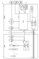
- FIG. 1 is a diagram showing an overall configuration of an endoscope system 1 according to an embodiment.
- the endoscope system 1 according to the present embodiment is an endoscope system used in transurethral ureteral lithotripsy (TUL). Specifically, in transurethral ureteral lithotripsy, the insertion section 21 of the endoscope 2 is inserted into the urinary tract to capture images of the inside of a subject, and a display image based on the captured image data is displayed on the display device 3.
- TUL transurethral ureteral lithotripsy
- the surgeon irradiates a laser beam from the laser irradiation device 5 toward a stone in the subject to fragment the stone, extracts the fragmented stone with a treatment tool such as a basket catheter, and leaves a medical device in the urinary tract for a predetermined period of time.
- the medical device is any one of a stent, a catheter, and an indwelling needle.
- the endoscope system 1 includes an endoscope 2, a display device 3, a control device 4, a laser irradiation device 5, and a perfusion device 6.
- the endoscope 2 generates image data (RAW data) by capturing an image of the inside of a subject, and outputs the image data to the control device 4.
- the endoscope 2 includes an insertion section 21, an operation section 22, and a universal cord 23.
- the insertion section 21 has at least a portion that is flexible and is inserted into a subject.
- the insertion section 21 includes a tip section 24 provided at the tip of the insertion section 21, a bending section 25 that is connected to a base end side (the operation section 22 side) of the tip section 24 and configured to be bendable, and a long flexible tube section 26 that is connected to the base end side of the bending section 25 and has flexibility.
- the operation unit 22 is connected to a base end portion of the insertion unit 21.
- the operation unit 22 receives various operations on the endoscope 2.
- the operation unit 22 is provided with a bending knob 221, an insertion port 222, and a plurality of operation members 223.
- the bending knob 221 is configured to be rotatable in response to a user operation by a user such as a surgeon.
- the bending knob 221 rotates to operate a bending mechanism (not shown) such as a metal or resin wire disposed in the insertion section 21. As a result, the bending section 25 is bent.
- the insertion port 222 communicates with a treatment instrument channel (not shown), which is a duct extending from the tip of the insertion portion 21, and is an insertion port for inserting a treatment instrument or the like into the treatment instrument channel from the outside of the endoscope 2.
- the multiple operating members 223 are composed of buttons and the like that accept various operations by a user such as an operator, and output operation signals corresponding to the various operations to the control device 4 via the universal cord 23.
- An example of the various operations is an operation to switch the observation mode of the endoscope system 1 between a normal light observation mode and a fluorescent observation mode.
- the universal cord 23 extends from the operation section 22 in a direction different from the extending direction of the insertion section 21, and is a cord on which a light guide 231 (see FIG. 2) made of an optical fiber or the like, a first signal line 232 (see FIG. 2) for transmitting the above-mentioned image data, a second signal line 233 (see FIG. 2) for transmitting the above-mentioned operation signal, etc. are arranged.
- first and second connector sections 27, 28 and a cable 27a are provided, as shown in FIG. 1.
- the first connector portion 27 is detachably connected to the control device 4 .
- the cable 27 a is a coiled cable extending from the first connector portion 27 .
- the second connector portion 28 is provided at the tip of the cable 27 a and is detachably connected to the control device 4 .
- the display device 3 is composed of a display monitor such as a liquid crystal or organic EL (Electro Luminescence) display monitor, and under the control of the control device 4, displays an image based on image data that has been subjected to image processing in the control device 4, as well as various information related to the endoscope system 1.
- a display monitor such as a liquid crystal or organic EL (Electro Luminescence) display monitor
- the control device 4 corresponds to the medical device according to the present invention.
- This control device 4 is realized using a processor, which is a processing device having hardware such as a GPU (Graphics Processing Unit), FPGA (Field Programmable Gate Array), or CPU (Central Processing Unit), and a memory, which is a temporary storage area used by the processor.
- the control device 4 comprehensively controls the operation of each part of the endoscope system 1 according to the program recorded in the memory.
- the laser irradiation device 5 irradiates a high-power infrared laser such as a Holmium YAG laser under the control of the control device 4. Specifically, the laser irradiation device 5 is inserted into the urinary tract (e.g., kidney, ureter, bladder, and urethra) from the insertion port 222 via a treatment tool channel in the insertion section 21. Then, the laser irradiation device 5 irradiates a laser toward stones that have developed in the subject in response to user operations by a user such as an operator. This causes the stones to break down.
- a high-power infrared laser such as a Holmium YAG laser
- the perfusion device 6 is constituted by a tube, a pump, etc., and communicates with a treatment instrument channel in the insertion portion 21 from an insertion port 222 as shown in FIG.
- the urinary tract is filled with an irrigation fluid such as physiological saline.
- the irrigation device 6 delivers the irrigation fluid into the urinary tract from the insertion port 222 through the treatment instrument channel in the insertion section 21, and discharges the irrigation fluid from the urinary tract to the outside of the urinary tract.
- FIG. 2 is a block diagram showing the functional configuration of the main parts of the endoscope system 1. As shown in FIG. In the following, the endoscope 2 and the control device 4 will be described in that order.
- the endoscope 2 includes an illumination optical system 201, an imaging optical system 202, a cut filter 203, an imaging element 204, an A/D conversion unit 205, a P/S conversion unit 206, an imaging recording unit 207, and an imaging control unit 208.
- the illumination optical system 201, the imaging optical system 202, the cut filter 203, the imaging element 204, the A/D conversion unit 205, the P/S conversion unit 206, the imaging recording unit 207, and the imaging control unit 208 are each disposed within the tip portion 24.
- the illumination optical system 201 is composed of one or more lenses and irradiates the subject with illumination light supplied from a light guide 231 .
- the imaging optical system 202 is composed of one or more lenses, etc., and focuses light such as reflected light from the subject, returned light from the subject, and fluorescent light emitted by the subject, to form an image of the subject on the light receiving surface of the image sensor 204.
- the cut filter 203 is disposed on the optical axis L1 of the imaging optical system 202, between the imaging optical system 202 and the imaging element 204. The cut filter 203 blocks light in a predetermined wavelength band and transmits other light. The transmission characteristics of the cut filter 203 will be described later in the section "Configuration of the Control Device.”
- the image sensor 204 is configured using a CCD (Charge Coupled Device) or CMOS (Complementary Metal Oxide Semiconductor) image sensor, in which one of the color filters constituting a Bayer array (RGGB) is arranged on each of a plurality of pixels arranged in a two-dimensional matrix.
- the image sensor control unit 208 Under the control of the image sensor control unit 208, the image sensor 204 receives the subject image formed by the image sensor optical system 202 via the cut filter 203, performs photoelectric conversion, generates image data (RAW data), and outputs it to the A/D conversion unit 205.
- CCD Charge Coupled Device
- CMOS Complementary Metal Oxide Semiconductor
- the A/D conversion unit 205 is configured using an A/D conversion circuit, etc., and performs A/D conversion processing on the analog image data input from the image sensor 204 under the control of the imaging control unit 208, and outputs the data to the P/S conversion unit 206.
- the P/S conversion unit 206 is constructed using a P/S conversion circuit, etc., and under the control of the imaging control unit 208, performs parallel/serial conversion on the digital image data (corresponding to the captured image of the present invention) input from the A/D conversion unit 205, and outputs it to the control device 4 via the first signal line 232.
- an E/O conversion unit that converts image data into an optical signal may be provided, and the image data may be output to the control device 4 by the optical signal.
- the image data may be transmitted to the control device 4 by wireless communication such as Wi-Fi (Wireless Fidelity) (registered trademark).
- the imaging and recording unit 207 is composed of a non-volatile memory or a volatile memory, and records various information related to the endoscope 2 (for example, pixel information of the imaging element 204, characteristics of the cut filter 203). The imaging and recording unit 207 also records various setting data and control parameters transmitted from the control device 4 via the second signal line 233.
- the imaging control unit 208 is realized using a TG (Timing Generator), a processor which is a processing device having hardware such as a CPU, and a memory which is a temporary storage area used by the processor.
- the imaging control unit 208 controls the operation of the imaging element 204, the A/D conversion unit 205, and the P/S conversion unit 206 based on the setting data received from the control device 4 via the second signal line 233.
- the control device 4 includes a focusing lens 401, a first light source unit 402, a second light source unit 403, a light source control unit 404, an S/P conversion unit 405, an image processing unit 406, an input unit 407, a recording unit 408, and a control unit 409.
- the condenser lens 401 condenses the light emitted by each of the first and second light source units 402 and 403 , and emits the light to the light guide 231 .
- the first light source unit 402 emits visible white light (normal light) under the control of the light source control unit 404, and supplies the white light as illumination light to the light guide 231.
- the first light source unit 402 is configured using a collimator lens, a white LED (Light Emitting Diode) lamp, a driving driver, and the like.
- the first light source unit 402 may be configured to supply visible white light by simultaneously emitting light from a red LED lamp, a green LED lamp, and a blue LED lamp.
- the first light source unit 402 may also be configured with a halogen lamp, a xenon lamp, or the like.
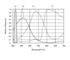
- Fig. 3 is a diagram showing wavelength characteristics of the excitation light emitted by the second light source unit 403. Specifically, in Fig. 3, the horizontal axis indicates wavelength (nm) and the vertical axis indicates wavelength characteristics. Also, in Fig. 3, curves L- V indicate wavelength characteristics of the excitation light emitted by the second light source unit 403. Furthermore, in Fig. 3, curves L- B indicate a blue wavelength band, curves L- G indicate a green wavelength band, and curves L- R indicate a red wavelength band.
- the second light source unit 403 emits excitation light having a central wavelength (peak wavelength) of 415 nm and a wavelength band of 400 nm to 430 nm, as shown in Fig. 3.
- This second light source unit 403 is configured using a collimator lens, a semiconductor laser such as a violet LD (laser diode), a driver, etc.
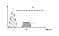
- Fig. 4 is a diagram showing the transmission characteristics of the cut filter 203.
- the horizontal axis indicates wavelength (nm) and the vertical axis indicates wavelength characteristics.
- a curve L- F indicates the transmission characteristics of the cut filter 203
- a curve L- V indicates the wavelength characteristics of the excitation light.
- a curve L- NG indicates the wavelength characteristics of the fluorescence generated by irradiating advanced glycation endproducts generated by thermal treatment of biological tissue with excitation light.
- thermal treatment of biological tissue means a state in which the laser irradiated from the laser irradiation device 5 to the calculus is irradiated to the biological tissue, or a state in which the laser-irradiated high-temperature calculus comes into contact with the biological tissue.
- the cut filter 203 blocks a portion of the excitation light reflected from the biological tissue in the observation area and transmits light in other wavelength bands including fluorescent components, as shown in Fig. 4.
- the cut filter 203 blocks a portion of light in the short-wavelength wavelength band of 400 nm to less than 430 nm, including the excitation light, and transmits light in the long-wavelength wavelength band of more than 430 nm, including fluorescence generated by irradiating the excitation light on advanced glycation endproducts generated by heat treatment.
- the light source control unit 404 is realized using a processor, which is a processing device having hardware such as an FPGA or a CPU, and a memory, which is a temporary storage area used by the processor.
- the light source control unit 404 controls the light emission timing and light emission time of each of the first and second light source units 402 and 403 based on control data input from the control unit 409.
- the S/P conversion unit 405 performs serial/parallel conversion on the image data received from the endoscope 2 via the first signal line 232 , and outputs the converted data to the image processing unit 406 .
- an O/E converter that converts an optical signal into an electrical signal may be provided instead of the S/P converter 405.
- a communication module capable of receiving wireless signals may be provided instead of the S/P converter 405.
- the image processing unit 406 is realized using a processor, which is a processing device having hardware such as a GPU or FPGA, and a memory, which is a temporary storage area used by the processor. Then, under the control of the control unit 409, the image processing unit 406 performs a predetermined image processing on the image data of the parallel data input from the S/P conversion unit 405, and outputs the result to the display device 3. Examples of the predetermined image processing include demosaic processing, white balance processing, gain adjustment processing, gamma correction processing, and format conversion processing.
- the input unit 407 is configured using a mouse, a foot switch, a keyboard, buttons, switches, a touch panel, etc., and accepts user operations by a user such as a surgeon, and outputs an operation signal corresponding to the user operation to the control unit 409.
- the recording unit 408 is configured using a recording medium such as a volatile memory, a non-volatile memory, an SSD (Solid State Drive), an HDD (Hard Disk Drive), a memory card, etc.
- the recording unit 408 records data including various parameters necessary for the operation of the endoscope system 1.
- the recording unit 408 also includes a program recording unit 408a that records various programs for operating the endoscope system 1.
- the control unit 409 corresponds to the processor according to the present invention.
- This control unit 409 is realized using a processor, which is a processing device having hardware such as an FPGA or a CPU, and a memory, which is a temporary storage area used by the processor.
- the control unit 409 comprehensively controls each unit constituting the endoscope system 1.
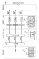
- FIG. 5 is a diagram for explaining the observation principle in the fluorescent observation mode.
- the control device 4 irradiates the biological tissue O10 with excitation light (center wavelength 415 nm) by emitting light from the second light source unit 403.
- the control device 4 irradiates the biological tissue O10 with excitation light (center wavelength 415 nm) by emitting light from the second light source unit 403.
- the reflected light (hereinafter referred to as reflected light W10) including at least the excitation light component reflected by the biological tissue O10 and the return light is blocked by the cut filter 203 and the intensity is reduced, while a part of the component on the longer wavelength side than the blocked wavelength band is incident on the image sensor 204 without reducing the intensity.
- the cut filter 203 blocks most of the reflected light W10 in a wavelength band on the short wavelength side including the wavelength band of the excitation light, which is incident on the G pixel of the image sensor 204, and transmits a wavelength band on the long wavelength side of the blocked wavelength band. Also, as shown in graph G12 of Fig. 5, the cut filter 203 transmits the fluorescence WF10 auto-emitted by advanced glycation endproducts generated by the thermal treatment of the biological tissue O10. Therefore, the reflected light W10 and the fluorescence WF10 with reduced intensity are incident on each of the R pixel, G pixel, and B pixel of the image sensor 204.
- the G pixel in the image sensor 204 has sensitivity to the fluorescence WF10.
- the fluorescence is a very small reaction.
- the output value according to the fluorescence WF10 at the G pixel is a small value.
- the image processing unit 406 acquires image data (RAW data) from the image sensor 204, performs image processing on the output values of each of the G and B pixels contained in the image data, and generates a fluorescent image.
- the output value of the G pixel contains fluorescent information corresponding to the fluorescence WF10 emitted from the heat-treated area (advanced glycation end products) where the thermal treatment of the biological tissue O10 has been performed.
- the output value of the B pixel contains background information from the biological tissue O10 of the subject, including the heat-treated area. Then, by displaying the fluorescent image on the display device 3, it becomes possible to observe the heat-treated area where the thermal treatment of the biological tissue O10 has been performed.
- FIG. 6 is a diagram for explaining the observation principle in the normal light observation mode.
- the control device 4 causes the first light source unit 402 to emit light, thereby irradiating the living tissue O10 with white light.
- a part of the reflected light and return light hereinafter, referred to as reflected light WR30, WG30, and WB30
- reflected light WR30, WG30, and WB30 a part of the reflected light and return light reflected by the living tissue O10 is blocked by the cut filter 203, and the rest is incident on the image sensor 204.
- the cut filter 203 blocks reflected light of a wavelength band on the short wavelength side including the wavelength band of the excitation light. Therefore, the light component of the blue wavelength band incident on the B pixel of the image sensor 204 becomes smaller than that in a state in which the cut filter 203 is not arranged.
- the image processing unit 406 acquires image data (RAW data) from the imaging element 204, performs image processing on the output values of each of the R, G, and B pixels contained in the image data, and generates an observation image (white light image).
- the image processing unit 406 performs a white balance adjustment process to adjust the white balance so that the ratio of the red, green, and blue components is constant. Then, by displaying the observation image (white light image) on the display device 3, it becomes possible to observe a natural observation image (white light image) even when the cut filter 203 is arranged.
- FIG. 7 is a flowchart showing a control method executed by the control device 4.
- FIG. 8 to FIG. 10 are diagrams for explaining the control method.
- FIG. 8 is a diagram showing a correlation (straight line L Y ) between the fluorescence intensity of the fluorescence auto-emitted by advanced glycation endproducts in the biological tissue and the invasiveness (depth and area) of the thermal treatment of the biological tissue.
- the vertical axis indicates the fluorescence intensity
- the horizontal axis indicates the invasiveness of the thermal treatment of the biological tissue.
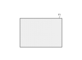
- FIG. 9 is a diagram showing a fluorescence image (first fluorescence image F1) generated in step S3.
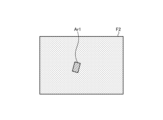
- FIG. 10 is a diagram showing a fluorescence image (second fluorescence image F2) generated in step S5.
- second fluorescence image F2 generated in step S5.
- illustration of stones reflected in the first and second fluorescence images F1 and F2 is omitted.
- the control method executed by the control device 4 during transurethral ureteral lithotripsy will be described below. That is, the insertion section 21 is inserted into the urinary tract, and the observation area of the endoscope system 1 is an area including the stone in the urinary tract.
- the laser irradiation device 5 is inserted into the urinary tract from the insertion port 222 via the treatment tool channel in the insertion section 21, and is in a state in which it can irradiate the stone with laser.
- control unit 409 executes normal control of the perfusion device 6, and the urinary tract is filled with perfusion fluid from the insertion port 222 via the treatment tool channel in the insertion section 21, and the perfusion fluid is perfused at a normal speed (the perfusion fluid is sent into the urinary tract while the perfusion fluid in the urinary tract is discharged outside the urinary tract), creating a normal state.
- the control unit 409 switches the observation mode to the fluorescence observation mode (step S1).
- the control unit 409 controls the light source control unit 404 to start irradiating the excitation light from the second light source unit 403 (step S2).
- the image processing unit 406 generates a fluorescent image (first fluorescent image F1 (FIG. 9)) based on the image data generated by the image sensor 204 (step S3).
- step S3 the control unit 409 controls the operation of the laser irradiation device 5 to irradiate the laser light from the laser irradiation device 5 (step S4). Then, the calculus in the urinary tract is broken up by the irradiation of the laser.
- step S4 the image processing unit 406 generates a fluorescent image (second fluorescent image F2 (FIG. 10)) based on the image data generated by the imaging element 204 (step S5).
- second fluorescent image F2 (FIG. 10)
- the shaded area Ar1 is a thermally altered area where thermal alteration has been enhanced by thermal treatment of the biological tissue. That is, the thermally altered area Ar1 corresponds to an area where thermal treatment has been performed by irradiating the laser irradiated to the stone in step S4 to the biological tissue, or an area where thermal treatment has been performed by contacting the high-temperature stone irradiated with the laser with the biological tissue.
- the first fluorescent image F1 shown in FIG. 9 is the same image as the observation area in the second fluorescent image F2, and is an image captured before the laser irradiation in step S4.
- the first fluorescent image F1 corresponds to the first captured image according to the present invention.
- the second fluorescent image F2 corresponds to the second captured image according to the present invention.
- step S6 determines a change in the state of thermal denaturation based on the first and second fluorescent images F1 and F2 (step S6).
- the control unit 409 determines a change in the state of thermal denaturation based on the difference in fluorescent intensity between corresponding pixels in the first and second fluorescent images F1 and F2.
- the fluorescence intensity used in step S6 may, for example, be at least the g value of the pixel values (r, g, b) of each pixel in the first and second fluorescence images F1 and F2 that have been subjected to demosaicing, or a luminance value corresponding to the Y signal (luminance signal).
- the change in the state of thermal denaturation is determined based on the first and second fluorescent images F1 and F2, but this is not limiting.
- the change in the state of thermal denaturation may be determined based on two sets of image data (captured images according to the present invention) that are taken one after the other before image processing is performed by the image processing unit 406.
- the output value of the G pixel in the image sensor 204 can be exemplified as the fluorescence intensity.
- step S6 the control unit 409 executes perfusion control (operation control of the perfusion device 6) based on the result of the determination of the change in state of thermal denaturation in step S6 (step S7).
- step S7 the perfusion control executed in step S7 can be exemplified by the following (1) to (3).
- the state change amount shown below is an amount indicating the size of the area where a change in state of thermal denaturation has occurred, or the strength of thermal denaturation in the area where a change in state of thermal denaturation has occurred.
- the state change amount determined from the first and second fluorescent images F1 and F2 is an amount indicating the size of the thermally denatured area Ar1, which is the area where a change in state of thermal denaturation has occurred, or the strength of the fluorescence intensity in the thermally denatured area Ar1.
- control unit 409 determines in step S6 that the amount of state change indicating the state change due to thermal denaturation is within the first amount of state change, it continues normal control of the perfusion device 6 and maintains the normal state in which the perfusion fluid is perfused at a normal speed.
- the above (1) perfusion control is performed in the examples of the first and second fluorescence images F1 and F2 when the size of the thermally denatured region Ar1 or the intensity of the fluorescence in the thermally denatured region Ar1 is within a first state change amount.
- step S6 When the control unit 409 determines in step S6 that the amount of state change indicating the state change of thermal denaturation exceeds the first amount of state change and is within a second amount of state change greater than the first amount of state change, the control unit 409 transmits a control signal to the perfusion device 6 to change the perfusion control of the perfusion device 6 from normal control to first control.
- the first control is a control for increasing the perfusion speed of the perfusion fluid from the normal speed to a first speed higher than the normal speed for a first time. Note that when the first time has elapsed, the control unit 409 transmits a control signal to the perfusion device 6 to change the perfusion control of the perfusion device 6 from the first control to normal control.
- control unit 409 determines in step S6 that the amount of state change indicating the state change of thermal denaturation exceeds the second amount of state change, it transmits a control signal to the perfusion device 6 to change the perfusion control of the perfusion device 6 from normal control to second control.
- the second control is a control for increasing the perfusion speed of the perfusion fluid from the normal speed to the first speed for a second time period that is longer than the first time period. Note that when the second time period has elapsed, the control unit 409 transmits a control signal to the perfusion device 6 to change the perfusion control of the perfusion device 6 from the second control to normal control.
- the above-mentioned (3) perfusion control is performed in the examples of the first and second fluorescence images F1 and F2 when the size of the thermally denatured region Ar1 or the intensity of the fluorescence in the thermally denatured region Ar1 exceeds the second state change amount.
- the perfusion control (4) below may be executed instead of the perfusion control (2) above, and the perfusion control (5) below may be executed instead of the perfusion control (3) above.
- the control unit 409 determines in step S6 that the amount of state change indicating the state change of thermal denaturation exceeds the first amount of state change and is within a second amount of state change greater than the first amount of state change, the control unit 409 transmits a control signal to the perfusion device 6 to change the perfusion control of the perfusion device 6 from normal control to third control.
- the third control is a control for increasing the perfusion speed of the perfusion fluid from the normal speed to the second speed for a third time. Note that when the third time has elapsed, the control unit 409 transmits a control signal to the perfusion device 6 to change the perfusion control of the perfusion device 6 from the third control to normal control.
- control unit 409 determines in step S6 that the amount of state change indicating the state change of thermal denaturation exceeds the second amount of state change, it sends a control signal to the perfusion device 6 and changes the perfusion control of the perfusion device 6 from normal control to fourth control.
- the fourth control is a control that increases the perfusion speed of the perfusion fluid from the normal speed to a third speed higher than the second speed for a third time. Note that when the third time has elapsed, the control unit 409 sends a control signal to the perfusion device 6 and returns the perfusion control of the perfusion device 6 from the fourth control to normal control.
- the control unit 409 determines a change in the state of thermal denaturation based on the fluorescent image, and changes the perfusion control of the perfusion device 6 based on the determination result of the change in the state of thermal denaturation. Therefore, when the laser irradiated on the stone is irradiated to living tissue during transurethral ureteral lithotripsy, or when a high-temperature stone irradiated with the laser comes into contact with living tissue, and a change in state of thermal denaturation of the living tissue occurs, the perfusion control described above in (2) to (5) can be performed.
- the control device 4 can appropriately control the perfusion in response to the effect of the laser irradiation on the living tissue.
- the control unit 409 judges the change in the state of thermal denaturation based on the difference in fluorescence intensity between corresponding pixels in the first and second fluorescent images F1 and F2, which are successive in time. Then, the control unit 409 performs the above-mentioned perfusion control (1) to (5) according to the size of the area where the change in the state of thermal denaturation has occurred or the amount of state change indicating the strength of the thermal denaturation in the area where the change in the state of thermal denaturation has occurred. Therefore, when it is necessary to cool the living tissue, the above-mentioned perfusion control (2) to (5) can be performed, and the living tissue can be appropriately cooled.
- the present invention should not be limited to the above-described embodiments.
- the medical device according to the present invention is mounted on an endoscope system used in transurethral ureteral lithotripsy, but the present invention is not limited to this and may be mounted on an endoscope system used in other procedures.
- the medical device according to the present invention is mounted on an endoscope system using a flexible endoscope, but the present invention is not limited to this and may also be mounted on an endoscope system using a rigid endoscope or an endoscope system using a medical surgery robot.
- control unit 409 may have a function as a learning unit of the learning device according to the present invention.
- the control device 4 corresponds to the learning device according to the present invention.
- the control unit 409 uses, as input data, a fluorescence image capturing the fluorescence generated from biological tissue when the biological tissue is irradiated with excitation light, and generates a trained model by machine learning using training data in which output data corresponds to a control signal that controls the operation of the perfusion device 6 based on the change in the state of thermal denaturation extracted from the fluorescence image.
- the trained model is composed of a neural network in which each layer has one or more nodes.
- the type of machine learning is not particularly limited, but may be, for example, a method in which teacher data and training data in which a plurality of fluorescent images of a subject are associated with information corresponding to a control signal for controlling the operation of the perfusion device 6 based on a change in the state of thermal denaturation extracted from the plurality of fluorescent images are prepared, and the teacher data and training data are input into a computational model based on a multilayer neural network for training.
- a method based on a deep neural network (DNN) of a multilayer neural network such as a convolutional neural network (CNN) or a 3D-CNN is used.
- a method based on a recurrent neural network (RNN) or long short-term memory units (LSTM) which is an extension of an RNN may be used.
- RNN recurrent neural network
- LSTM long short-term memory units
- a learning unit of a learning device different from the control device 4 may execute these functions.
Landscapes
- Health & Medical Sciences (AREA)
- Life Sciences & Earth Sciences (AREA)
- Engineering & Computer Science (AREA)
- Surgery (AREA)
- Physics & Mathematics (AREA)
- Medical Informatics (AREA)
- Biomedical Technology (AREA)
- General Health & Medical Sciences (AREA)
- Public Health (AREA)
- Optics & Photonics (AREA)
- Molecular Biology (AREA)
- Animal Behavior & Ethology (AREA)
- Heart & Thoracic Surgery (AREA)
- Veterinary Medicine (AREA)
- Nuclear Medicine, Radiotherapy & Molecular Imaging (AREA)
- Pathology (AREA)
- Biophysics (AREA)
- Radiology & Medical Imaging (AREA)
- Signal Processing (AREA)
- Evolutionary Computation (AREA)
- Artificial Intelligence (AREA)
- Business, Economics & Management (AREA)
- General Business, Economics & Management (AREA)
- Epidemiology (AREA)
- Primary Health Care (AREA)
- Electromagnetism (AREA)
- Otolaryngology (AREA)
- Quality & Reliability (AREA)
- Computer Vision & Pattern Recognition (AREA)
- General Physics & Mathematics (AREA)
- Theoretical Computer Science (AREA)
- Endoscopes (AREA)
Abstract
Description
特許文献1に記載の技術では、生体組織に対する励起光の照射によって当該生体組織から発生した蛍光を撮像した撮像画像に基づいて、当該生体組織の熱変性の状態を可視化している。具体的に、特許文献1に記載の技術では、当該撮像画像の全画素のうち、蛍光強度が予め設定された蛍光強度よりも高い領域を熱変性が高い領域として検出する。
ここで、特許文献1に記載の技術を適用した場合には、生体組織における熱変性の状態を可視化することはできるが、レーザ照射による生体組織への作用に対して適切に対応することは難しい。
図1は、実施の形態に係る内視鏡システム1の全体構成を示す図である。
本実施の形態に係る内視鏡システム1は、経尿道的尿管結石破砕術(TUL)において用いられる内視鏡システムである。具体的に、経尿道的尿管結石破砕術では、内視鏡2の挿入部21を尿路へ挿入することによって被検体内を撮像し、当該撮像した画像データに基づく表示画像を表示装置3に表示する。そして、術者は、当該表示画像を確認しながら、レーザ照射装置5から被検体内の結石に向けてレーザを照射することによって当該結石を破砕し、当該破砕した結石をバスケットカテーテル等の処置具によって摘出を行い、尿路内に医療器具を所定期間するまで留置する。ここで、医療器具は、ステント、カテーテル、及び留置針のいずれか1つである。
この内視鏡システム1は、図1に示すように、内視鏡2と、表示装置3と、制御装置4と、レーザ照射装置5と、灌流装置6とを備える。
挿入部21は、少なくとも一部が可撓性を有し、被検体内に挿入される。この挿入部21は、図1に示すように、当該挿入部21の先端に設けられた先端部24と、当該先端部24の基端側(操作部22側)に連結され、湾曲可能に構成された湾曲部25と、当該湾曲部25の基端側に連結され、可撓性を有する長尺状の可撓管部26とを備える。
湾曲ノブ221は、術者等のユーザによるユーザ操作に応じて回動可能に構成されている。そして、湾曲ノブ221は、回動することによって、挿入部21内に配設された金属製または樹脂製のワイヤ等の湾曲機構(図示略)を動作させる。これによって、湾曲部25は、湾曲する。
複数の操作部材223は、術者等のユーザによる各種操作を受け付けるボタン等によって構成され、ユニバーサルコード23を経由することによって、当該各種操作に応じた操作信号を制御装置4へ出力する。当該各種操作としては、内視鏡システム1の観察モードを通常光観察モードまたは蛍光観察モードに切り替える操作等を例示することができる。
第1のコネクタ部27は、制御装置4に対して着脱自在に接続される。
ケーブル27aは、第1のコネクタ部27から延在するコイル状のケーブルである。
第2のコネクタ部28は、ケーブル27aの先端に設けられ、制御装置4に対して着脱自在に接続される。
ここで、尿路内は、生理食塩水等の灌流液によって満たされている。そして、灌流装置6は、制御装置4による制御の下、挿入口222から挿入部21内の処置具チャンネルを経由することによって、灌流液を尿路内に送出するとともに、当該尿路内の灌流液を当該尿路外に排出する。
次に、上述した内視鏡システム1の要部の機能構成について説明する。
図2は、内視鏡システム1の要部の機能構成を示すブロック図である。
以下では、内視鏡2及び制御装置4の順に説明する。
先ず、内視鏡2の構成について説明する。
内視鏡2は、図2に示すように、照明光学系201と、撮像光学系202と、カットフィルタ203と、撮像素子204と、A/D変換部205と、P/S変換部206と、撮像記録部207と、撮像制御部208とを備える。
ここで、照明光学系201、撮像光学系202、カットフィルタ203、撮像素子204、A/D変換部205、P/S変換部206、撮像記録部207、及び撮像制御部208の各々は、先端部24内に配置されている。
撮像光学系202は、1または複数のレンズ等によって構成され、被写体から反射された反射光、当該被写体からの戻り光、当該被写体が発光した蛍光等の光を集光することによって被写体像を撮像素子204の受光面上に結像する。
カットフィルタ203は、撮像光学系202の光軸L1上において、当該撮像光学系202と撮像素子204との間に配置される。そして、カットフィルタ203は、所定の波長帯域の光を遮光し、その他の光を透過する。
なお、カットフィルタ203の透過特性については、後述する「制御装置の構成」において説明する。
なお、P/S変換部206の代わりに、画像データを光信号に変換するE/O変換部を設け、当該光信号によって制御装置4へ画像データを出力する構成としてもよい。また、例えばWi-Fi(Wireless Fidelity)(登録商標)等の無線通信によって画像データを制御装置4へ送信する構成としても構わない。
次に、制御装置4の構成について説明する。
制御装置4は、図2に示すように、集光レンズ401と、第1の光源部402と、第2の光源部403と、光源制御部404と、S/P変換部405と、画像処理部406と、入力部407と、記録部408と、制御部409とを備える。
集光レンズ401は、第1,第2の光源部402,403の各々が発光した光を集光し、ライトガイド231へ出射する。
なお、第1の光源部402としては、赤色LEDランプ、緑色LEDランプ、及び青色LEDランプを用いて同時に発光することによって可視光の白色光を供給しても構わない。また、第1の光源部402としては、ハロゲンランプやキセノンランプ等によって構成しても構わない。
図3は、第2の光源部403が発光する励起光の波長特性を示す図である。具体的に、図3において、横軸が波長(nm)を示し、縦軸が波長特性を示す。また、図3において、曲線LVが第2の光源部403が発光する励起光の波長特性を示す。さらに、図3において、曲線LBが青色の波長帯域を示し、曲線LGが緑色の波長帯域を示し、曲線LRが赤色の波長帯域を示す。
本実施の形態では、第2の光源部403は、図3に示すように、中心波長(ピーク波長)が415nmであり、波長帯域が400nm~430nmである励起光を発光する。この第2の光源部403は、コリメートレンズ、紫色LD(laser Diode)等の半導体レーザ、及び駆動ドライバ等を用いて構成される。
図4は、カットフィルタ203の透過特性を示す図である。具体的に、図4において、横軸が波長(nm)を示し、縦軸が波長特性を示す。また、図4において、曲線LFがカットフィルタ203の透過特性を示し、曲線LVが励起光の波長特性を示す。さらに、図4において、曲線LNGが生体組織への熱処置によって生じる終末糖化産物に対して励起光を照射することによって生じる蛍光の波長特性を示す。本実施の形態において、生体組織への熱処置としては、レーザ照射装置5から結石へ照射されたレーザが生体組織にまで照射された状態や、レーザ照射された高温の結石が生体組織と接触した状態を意味する。
本実施の形態では、カットフィルタ203は、図4に示すように、観察領域の生体組織から反射された励起光の一部を遮光し、蛍光成分を含む他の波長帯域の光を透過する。より具体的に、カットフィルタ203は、励起光を含む400nm~430nm未満の短波長側の波長帯域の光の一部を遮光し、かつ、熱処置によって生じる終末糖化産物に対して励起光を照射することによって生じる蛍光を含む430nmよりも長波長側の波長帯域の光を透過する。
なお、内視鏡2が光信号で画像データを出力する場合、S/P変換部405の代わりに、光信号を電気信号に変換するO/E変換部を設けても構わない。また、内視鏡2が無線通信によって画像データを送信する場合、S/P変換部405の代わりに、無線信号を受信可能な通信モジュールを設けても構わない。
次に、内視鏡システム1の観察モードにおける観察原理について説明する。
以下では、蛍光観察モード及び通常光観察モードの順に説明する。
先ず、蛍光観察モードにおける観察原理について説明する。
図5は、蛍光観察モードにおける観察原理を説明する図である。
図5のグラフG11に示すように、先ず、制御装置4は、第2の光源部403を発光させることによって、励起光(中心波長415nm)を生体組織O10に照射する。この場合、図5のグラフG12に示すように、少なくとも生体組織O10で反射された励起光の成分及び戻り光を含む反射光(以下、反射光W10と記載)は、カットフィルタ203によって遮光され強度が低下する一方、当該遮光する波長帯域よりも長波長側の成分の一部は強度を落とさずに撮像素子204に入射する。
ここで、撮像素子204におけるG画素は、蛍光WF10に感度を有する。しかしながら、図5のグラフG12における蛍光特性の曲線LNGに示すように、蛍光が微小な反応である。このため、G画素における蛍光WF10に応じた出力値は、小さい値となる。
次に、通常光観察モードにおける観察原理について説明する。
図6は、通常光観察モードにおける観察原理を説明する図である。
図6のグラフG21に示すように、先ず、制御装置4は、第1の光源部402を発光させることによって、白色光を生体組織O10に照射する。この場合、生体組織O10で反射された反射光及び戻り光(以下、反射光WR30,WG30,WB30と記載)は、一部がカットフィルタ203によって遮光され、残りが撮像素子204に入射する。具体的には、図6のグラフG22に示すように、カットフィルタ203は、励起光の波長帯域を含む短波長側の波長帯域の反射光を遮光する。このため、撮像素子204におけるB画素に入射する青色の波長帯域の光の成分が、カットフィルタ203を配置していない状態と比べて小さくなる。
次に、制御装置4が実行する制御方法について説明する。
図7は、制御装置4が実行する制御方法を示すフローチャートである。図8ないし図10は、制御方法を説明する図である。具体的に、図8は、生体組織における終末糖化産物が自家発光した蛍光の蛍光強度と、当該生体組織への熱処置による侵襲度(深度及び領域)との相関関係(直線LY)を示す図である。なお、図8において、縦軸が蛍光強度を示し、横軸が生体組織への熱処置による侵襲度を示している。図9は、ステップS3において生成される蛍光画像(第1の蛍光画像F1)を示す図である。図10は、ステップS5において生成される蛍光画像(第2の蛍光画像F2)を示す図である。ここで、図9及び図10では、説明の便宜上、第1,第2の蛍光画像F1,F2に写り込んでいる結石の図示を省略している。
ステップS1の後、制御部409は、光源制御部404を制御することによって、第2の光源部403からの励起光の照射を開始させる(ステップS2)。
ステップS2の後、画像処理部406は、撮像素子204が生成した画像データに基づいて、蛍光画像(第1の蛍光画像F1(図9))を生成する(ステップS3)。
ステップS4の後、画像処理部406は、撮像素子204が生成した画像データに基づいて、蛍光画像(第2の蛍光画像F2(図10))を生成する(ステップS5)。
そこで、本実施の形態では、以下に示すステップS6,S7を実行することによって、レーザ照射による生体組織への作用に対して適切に対応する。
具体的に、制御部409は、ステップS5の後、第1,第2の蛍光画像F1,F2に基づいて、熱変性の状態変化を判断する(ステップS6)。本実施の形態では、制御部409は、第1,第2の蛍光画像F1,F2における対応する画素同士の蛍光強度の差に基づいて、熱変性の状態変化を判断する。
なお、ステップS6では、第1,第2の蛍光画像F1,F2に基づいて、熱変性の状態変化を判断していたが、これに限らない。例えば、画像処理部406によって画像処理が施される前の時間的に前後する2つの画像データ(本発明に係る撮像画像)に基づいて、熱変性の状態変化を判断しても構わない。この際、蛍光強度としては、撮像素子204におけるG画素の出力値を例示することができる。
具体的に、ステップS7において実行する灌流制御としては、以下の(1)~(3)を例示することができる。なお、以下に示す状態変化量は、熱変性の状態変化が生じた領域の広さ、または、熱変性の状態変化が生じた領域の熱変性の強さを示す量である。例えば、第1,第2の蛍光画像F1,F2から判断される状態変化量としては、熱変性の状態変化が生じた領域である熱変性領域Ar1の広さ、または、当該熱変性領域Ar1における蛍光強度の強さを示す量である。
上記(1)の灌流制御は、第1,第2の蛍光画像F1,F2の例では、熱変性領域Ar1の広さ、または、当該熱変性領域Ar1における蛍光強度の強さが第1の状態変化量以内の場合に実行される。
上記(2)の灌流制御は、第1,第2の蛍光画像F1,F2の例では、熱変性領域Ar1の広さ、または、当該熱変性領域Ar1における蛍光強度の強さが第1の状態変化量を超え、かつ、第2の状態変化量以内の場合に実行される。
上記(3)の灌流制御は、第1,第2の蛍光画像F1,F2の例では、熱変性領域Ar1の広さ、または、当該熱変性領域Ar1における蛍光強度の強さが第2の状態変化量を超える場合に実行される。
(4)制御部409は、ステップS6において熱変性の状態変化を示す状態変化量が第1の状態変化量を超え、かつ、当該第1の状態変化量よりも多い第2の状態変化量以内であると判断した場合には、灌流装置6へ制御信号を送信し、当該灌流装置6の灌流制御を通常制御から第3の制御へ変更する。当該第3の制御は、第3の時間の間、灌流液の灌流の速度を通常速度から第2の速度まで増加させる制御である。なお、制御部409は、第3の時間が経過した場合には、灌流装置6へ制御信号を送信し、当該灌流装置6の灌流制御を第3の制御から通常制御へ戻す。
本実施の形態に係る制御装置4では、制御部409は、蛍光画像に基づいて、熱変性の状態変化を判断し、当該熱変性の状態変化の判断結果に基づいて、灌流装置6の灌流制御を変更する。
このため、経尿道的尿管結石破砕術が行われている最中に、結石へ照射したレーザが生体組織にまで照射された場合や、レーザ照射された高温の結石が生体組織と接触した場合等において、当該生体組織の熱変性の状態変化が生じた時に、例えば上述した(2)~(5)の灌流制御を行うことができる。そして、熱変性の状態変化が生じた生体組織は、当該灌流制御による灌流液によって即座に冷却されることとなる。したがって、本実施の形態に係る制御装置4によれば、レーザ照射による生体組織への作用に対して適切に灌流を制御することができる。
このため、生体組織を冷やす必要のある時に上述した(2)~(5)の灌流制御を行うことができ、当該生体組織を適切に冷却することができる。
ここまで、本発明を実施するための形態を説明してきたが、本発明は上述した実施の形態によってのみ限定されるべきものではない。
上述した実施の形態では、本発明に係る医療用装置を経尿道的尿管結石破砕術において用いられる内視鏡システムに搭載していたが、これに限らず、その他の手技において用いられる内視鏡システムに搭載しても構わない。
具体的に、制御部409は、生体組織に対する励起光の照射によって当該生体組織から発生した蛍光を撮像した蛍光画像を入力データとし、当該蛍光画像から抽出した熱変性の状態変化に基づいて灌流装置6の動作を制御する制御信号に応じた情報を出力データとする教師データを用いて機械学習することにより学習済みモデルを生成する。
ここで、学習済みモデルは、各層が一または複数のノードを有するニューラルネットワークからなる。また、機械学習の種類は、特に限定されないが、例えば複数の被検体の蛍光画像と、この複数の蛍光画像から抽出した熱変性の状態変化に基づいて灌流装置6の動作を制御する制御信号に応じた情報とを対応付けた教師用データ及び学習用データを用意し、この教師用データ及び学習用データを多層ニューラルネットワークに基づいた計算モデルに入力して学習されるものであればよい。さらに、機械学習の手法としては、例えばCNN(Convolutional Neural Network)、3D-CNN等の多層のニューラルネットワークのDNN(Deep Neural Network)に基づく手法が用いられる。さらにまた、機械学習の手法としては、再帰型ニューラルネットワーク(RNN:Recurrent Neural Network)やRNNを拡張したLSTM(Long Short-Term Memory units)等に基づく手法が用いられてもよい。なお、制御装置4とは異なる学習装置の学習部がこれらの機能を実行してもよい。
2 内視鏡
3 表示装置
4 制御装置
5 レーザ照射装置
6 灌流装置
21 挿入部
22 操作部
23 ユニバーサルコード
24 先端部
25 湾曲部
26 可撓管部
27 第1のコネクタ部
27a ケーブル
28 第2のコネクタ部
201 照明光学系
202 撮像光学系
203 カットフィルタ
204 撮像素子
205 A/D変換部
206 P/S変換部
207 撮像記録部
208 撮像制御部
221 湾曲ノブ
222 挿入口
223 操作部材
231 ライトガイド
232 第1の信号線
233 第2の信号線
401 集光レンズ
402 第1の光源部
403 第2の光源部
404 光源制御部
405 S/P変換部
406 画像処理部
407 入力部
408 記録部
408a プログラム記録部
409 制御部
Ar1 熱変性領域
F1 第1の蛍光画像
F2 第2の蛍光画像
G11~G13,G21~G23 グラフ
L1 光軸
LB,LG,LR,LV 曲線
LF カットフィルタの透過特性
LNG 蛍光の波長特性
LY 直線
O10 生体組織
W10,WB30,WG30,WR30 反射光
WF10 蛍光
Claims (16)
- 生体組織に対する励起光の照射によって前記生体組織から発生した蛍光を撮像した撮像画像を処理するプロセッサを備え、
前記プロセッサは、
前記撮像画像に基づいて、熱変性の状態変化を判断し、
前記熱変性の状態変化の判断結果に基づいて、灌流液を灌流させる灌流装置の動作を制御する制御信号を前記灌流装置へ送信する医療用装置。 - 前記プロセッサは、
前記熱変性の状態変化の判断結果に基づいて、前記灌流液の灌流の速度を増加させるための前記制御信号を前記灌流装置へ送信する請求項1に記載の医療用装置。 - 前記プロセッサは、
前記熱変性の状態変化の判断結果に基づいて、第1の時間の間、前記灌流液の灌流の速度を増加させるための前記制御信号を前記灌流装置へ送信する請求項1に記載の医療用装置。 - 前記プロセッサは、
時間的に前後する2つの前記撮像画像から前記熱変性の状態変化を判断する請求項1に記載の医療用装置。 - 前記時間的に前後する2つの前記撮像画像は、
レーザが照射される前に撮像した第1の撮像画像と、
前記レーザが照射された後に撮像した第2の撮像画像とである請求項4に記載の医療用装置。 - 前記プロセッサは、
前記時間的に前後する2つの前記撮像画像における対応する画素同士の蛍光強度の差に基づいて、前記熱変性の状態変化を判断する請求項4に記載の医療用装置。 - 前記プロセッサは、
前記熱変性の状態変化を示す状態変化量が第1の状態変化量を超え、かつ、前記第1の状態変化量よりも多い第2の状態変化量以内であると判断した場合には、第1の時間の間、前記灌流液の灌流の速度を第1の速度まで増加させるための前記制御信号を前記灌流装置へ送信する請求項1に記載の医療用装置。 - 前記プロセッサは、
前記熱変性の状態変化を示す状態変化量が前記第2の状態変化量を超えると判断した場合には、前記第1の時間よりも長い第2の時間の間、前記灌流液の灌流の速度を前記第1の速度まで増加させるための前記制御信号を前記灌流装置へ送信する請求項7に記載の医療用装置。 - 前記プロセッサは、
前記熱変性の状態変化を示す状態変化量が第1の状態変化量を超え、かつ、前記第1の状態変化量よりも多い第2の状態変化量以内であると判断した場合には、第3の時間の間、前記灌流液の灌流の速度を第2の速度まで増加させるための前記制御信号を前記灌流装置へ送信する請求項1に記載の医療用装置。 - 前記プロセッサは、
前記熱変性の状態変化を示す状態変化量が前記第2の状態変化量を超えると判断した場合には、前記第3の時間の間、前記灌流液の灌流の速度を前記第2の速度よりも高い第3の速度まで増加させるための前記制御信号を前記灌流装置へ送信する請求項9に記載の医療用装置。 - 前記熱変性の状態変化を示す状態変化量は、
前記熱変性の状態変化が生じた領域の広さ、または、前記熱変性の状態変化が生じた領域の前記熱変性の強さを示す請求項7に記載の医療用装置。 - 前記蛍光は、
前記生体組織に対して熱処置を施すことによって生じる終末糖化産物から発生する請求項1に記載の医療用装置。 - 励起光を照射する光源装置と、
被検体内に挿入可能とし、前記被検体内の生体組織に対する前記励起光の照射によって前記生体組織から発生した蛍光を撮像した撮像画像を出力する内視鏡と、
前記撮像画像を処理するプロセッサを有する医療用装置と、を備え、
前記プロセッサは、
前記撮像画像に基づいて、熱変性の状態変化を判断し、
前記熱変性の状態変化の判断結果に基づいて、灌流液を灌流させる灌流装置の動作を制御する制御信号を前記灌流装置へ送信する内視鏡システム。 - 医療用装置が実行する制御方法であって、
生体組織に対する励起光の照射によって前記生体組織から発生した蛍光を撮像した撮像画像に基づいて、熱変性の状態変化を判断し、
前記熱変性の状態変化の判断結果に基づいて、灌流液を灌流させる灌流装置の動作を制御する制御信号を前記灌流装置へ送信する制御方法。 - 医療用装置に実行させる制御プログラムであって、
前記制御プログラムは、前記医療用装置に以下の実行を指示する:
生体組織に対する励起光の照射によって前記生体組織から発生した蛍光を撮像した撮像画像に基づいて、熱変性の状態変化を判断し、
前記熱変性の状態変化の判断結果に基づいて、灌流液を灌流させる灌流装置の動作を制御する制御信号を前記灌流装置へ送信する制御プログラム。 - 生体組織に対する励起光の照射によって前記生体組織から発生した蛍光を撮像した蛍光画像を入力データとし、前記蛍光画像から抽出した熱変性の状態変化に基づいて灌流液を灌流させる灌流装置の動作を制御する制御信号に応じた情報を出力データとする教師データを用いて機械学習することにより学習済みモデルを生成する学習部を備える学習装置。
Priority Applications (3)
| Application Number | Priority Date | Filing Date | Title |
|---|---|---|---|
| PCT/JP2023/004452 WO2024166325A1 (ja) | 2023-02-09 | 2023-02-09 | 医療用装置、内視鏡システム、制御方法、制御プログラム、及び学習装置 |
| CN202380093302.5A CN120659570A (zh) | 2023-02-09 | 2023-02-09 | 医疗用装置、内窥镜系统、控制方法、控制程序以及学习装置 |
| US19/290,756 US20250359934A1 (en) | 2023-02-09 | 2025-08-05 | Medical device, endoscope system, control method, computer-readable recording medium, and learning device |
Applications Claiming Priority (1)
| Application Number | Priority Date | Filing Date | Title |
|---|---|---|---|
| PCT/JP2023/004452 WO2024166325A1 (ja) | 2023-02-09 | 2023-02-09 | 医療用装置、内視鏡システム、制御方法、制御プログラム、及び学習装置 |
Related Child Applications (1)
| Application Number | Title | Priority Date | Filing Date |
|---|---|---|---|
| US19/290,756 Continuation US20250359934A1 (en) | 2023-02-09 | 2025-08-05 | Medical device, endoscope system, control method, computer-readable recording medium, and learning device |
Publications (1)
| Publication Number | Publication Date |
|---|---|
| WO2024166325A1 true WO2024166325A1 (ja) | 2024-08-15 |
Family
ID=92262155
Family Applications (1)
| Application Number | Title | Priority Date | Filing Date |
|---|---|---|---|
| PCT/JP2023/004452 Ceased WO2024166325A1 (ja) | 2023-02-09 | 2023-02-09 | 医療用装置、内視鏡システム、制御方法、制御プログラム、及び学習装置 |
Country Status (3)
| Country | Link |
|---|---|
| US (1) | US20250359934A1 (ja) |
| CN (1) | CN120659570A (ja) |
| WO (1) | WO2024166325A1 (ja) |
Citations (1)
| Publication number | Priority date | Publication date | Assignee | Title |
|---|---|---|---|---|
| WO2020174666A1 (ja) * | 2019-02-28 | 2020-09-03 | オリンパス株式会社 | 医療用システム |
-
2023
- 2023-02-09 WO PCT/JP2023/004452 patent/WO2024166325A1/ja not_active Ceased
- 2023-02-09 CN CN202380093302.5A patent/CN120659570A/zh active Pending
-
2025
- 2025-08-05 US US19/290,756 patent/US20250359934A1/en active Pending
Patent Citations (1)
| Publication number | Priority date | Publication date | Assignee | Title |
|---|---|---|---|---|
| WO2020174666A1 (ja) * | 2019-02-28 | 2020-09-03 | オリンパス株式会社 | 医療用システム |
Also Published As
| Publication number | Publication date |
|---|---|
| CN120659570A (zh) | 2025-09-16 |
| US20250359934A1 (en) | 2025-11-27 |
Similar Documents
| Publication | Publication Date | Title |
|---|---|---|
| JP5606120B2 (ja) | 内視鏡装置 | |
| US20230000330A1 (en) | Medical observation system, medical imaging device and imaging method | |
| CN109195502B (zh) | 活体观察系统 | |
| JP2012213551A (ja) | 生体情報取得システムおよび生体情報取得方法 | |
| US20230248209A1 (en) | Assistant device, endoscopic system, assistant method, and computer-readable recording medium | |
| WO2015093114A1 (ja) | 内視鏡装置 | |
| US12121219B2 (en) | Medical image processing device, medical imaging device, medical observation system, image processing method, and computer-readable recording medium | |
| WO2024166325A1 (ja) | 医療用装置、内視鏡システム、制御方法、制御プログラム、及び学習装置 | |
| JP5897663B2 (ja) | 内視鏡装置 | |
| JP7434591B2 (ja) | 支援装置、内視鏡システム、支援方法およびプログラム | |
| WO2024166308A1 (ja) | 医療用装置、医療用システム、学習装置、医療用装置の作動方法およびプログラム | |
| WO2024166310A1 (ja) | 医療用装置、医療用システム、学習装置、医療用装置の作動方法およびプログラム | |
| WO2024166328A1 (ja) | 医療用装置、医療用システム、学習装置、医療用装置の作動方法およびプログラム | |
| WO2024166330A1 (ja) | 医療用装置、医療用システム、医療用装置の作動方法およびプログラム | |
| WO2024166327A1 (ja) | 医療用装置、医療用システム、医療用装置の作動方法およびプログラム | |
| US20250356490A1 (en) | Assistance device, operation method of assistance device, computer-readable recording medium, medical system, and learning device | |
| WO2024166309A1 (ja) | 医療用装置、内視鏡システム、制御方法、制御プログラム、及び学習装置 | |
| JP7796922B2 (ja) | 医療画像処理装置、医療画像処理方法、プログラム、及び記録媒体 | |
| WO2024166311A1 (ja) | 画像処理装置、医療システム、画像処理装置の作動方法、及び学習装置 | |
| WO2024166306A1 (ja) | 医療用装置、内視鏡システム、制御方法、制御プログラム、及び学習装置 | |
| WO2024166307A1 (ja) | 医療用装置、医療システム、医療用装置の作動方法、および、医療用装置の作動プログラム | |
| JP6104419B2 (ja) | 内視鏡装置 | |
| WO2024166312A1 (ja) | 医療用装置、内視鏡システム、制御方法、及び制御プログラム |
Legal Events
| Date | Code | Title | Description |
|---|---|---|---|
| 121 | Ep: the epo has been informed by wipo that ep was designated in this application |
Ref document number: 23921156 Country of ref document: EP Kind code of ref document: A1 |
|
| WWE | Wipo information: entry into national phase |
Ref document number: 202380093302.5 Country of ref document: CN |
|
| NENP | Non-entry into the national phase |
Ref country code: DE |
|
| WWP | Wipo information: published in national office |
Ref document number: 202380093302.5 Country of ref document: CN |
|
| 122 | Ep: pct application non-entry in european phase |
Ref document number: 23921156 Country of ref document: EP Kind code of ref document: A1 |