WO2024166330A1 - 医療用装置、医療用システム、医療用装置の作動方法およびプログラム - Google Patents
医療用装置、医療用システム、医療用装置の作動方法およびプログラム Download PDFInfo
- Publication number
- WO2024166330A1 WO2024166330A1 PCT/JP2023/004457 JP2023004457W WO2024166330A1 WO 2024166330 A1 WO2024166330 A1 WO 2024166330A1 JP 2023004457 W JP2023004457 W JP 2023004457W WO 2024166330 A1 WO2024166330 A1 WO 2024166330A1
- Authority
- WO
- WIPO (PCT)
- Prior art keywords
- image
- blood vessel
- medical device
- light
- processor
- Prior art date
- Legal status (The legal status is an assumption and is not a legal conclusion. Google has not performed a legal analysis and makes no representation as to the accuracy of the status listed.)
- Ceased
Links
Images


Classifications
-
- G—PHYSICS
- G06—COMPUTING OR CALCULATING; COUNTING
- G06T—IMAGE DATA PROCESSING OR GENERATION, IN GENERAL
- G06T7/00—Image analysis
- G06T7/0002—Inspection of images, e.g. flaw detection
- G06T7/0012—Biomedical image inspection
-
- A—HUMAN NECESSITIES
- A61—MEDICAL OR VETERINARY SCIENCE; HYGIENE
- A61B—DIAGNOSIS; SURGERY; IDENTIFICATION
- A61B1/00—Instruments for performing medical examinations of the interior of cavities or tubes of the body by visual or photographical inspection, e.g. endoscopes; Illuminating arrangements therefor
- A61B1/00002—Operational features of endoscopes
- A61B1/00004—Operational features of endoscopes characterised by electronic signal processing
- A61B1/00006—Operational features of endoscopes characterised by electronic signal processing of control signals
-
- A—HUMAN NECESSITIES
- A61—MEDICAL OR VETERINARY SCIENCE; HYGIENE
- A61B—DIAGNOSIS; SURGERY; IDENTIFICATION
- A61B1/00—Instruments for performing medical examinations of the interior of cavities or tubes of the body by visual or photographical inspection, e.g. endoscopes; Illuminating arrangements therefor
- A61B1/00002—Operational features of endoscopes
- A61B1/00004—Operational features of endoscopes characterised by electronic signal processing
- A61B1/00009—Operational features of endoscopes characterised by electronic signal processing of image signals during a use of endoscope
- A61B1/000094—Operational features of endoscopes characterised by electronic signal processing of image signals during a use of endoscope extracting biological structures
-
- A—HUMAN NECESSITIES
- A61—MEDICAL OR VETERINARY SCIENCE; HYGIENE
- A61B—DIAGNOSIS; SURGERY; IDENTIFICATION
- A61B1/00—Instruments for performing medical examinations of the interior of cavities or tubes of the body by visual or photographical inspection, e.g. endoscopes; Illuminating arrangements therefor
- A61B1/00002—Operational features of endoscopes
- A61B1/00043—Operational features of endoscopes provided with output arrangements
- A61B1/00045—Display arrangement
- A61B1/0005—Display arrangement combining images e.g. side-by-side, superimposed or tiled
-
- A—HUMAN NECESSITIES
- A61—MEDICAL OR VETERINARY SCIENCE; HYGIENE
- A61B—DIAGNOSIS; SURGERY; IDENTIFICATION
- A61B1/00—Instruments for performing medical examinations of the interior of cavities or tubes of the body by visual or photographical inspection, e.g. endoscopes; Illuminating arrangements therefor
- A61B1/04—Instruments for performing medical examinations of the interior of cavities or tubes of the body by visual or photographical inspection, e.g. endoscopes; Illuminating arrangements therefor combined with photographic or television appliances
- A61B1/043—Instruments for performing medical examinations of the interior of cavities or tubes of the body by visual or photographical inspection, e.g. endoscopes; Illuminating arrangements therefor combined with photographic or television appliances for fluorescence imaging
-
- A—HUMAN NECESSITIES
- A61—MEDICAL OR VETERINARY SCIENCE; HYGIENE
- A61B—DIAGNOSIS; SURGERY; IDENTIFICATION
- A61B1/00—Instruments for performing medical examinations of the interior of cavities or tubes of the body by visual or photographical inspection, e.g. endoscopes; Illuminating arrangements therefor
- A61B1/04—Instruments for performing medical examinations of the interior of cavities or tubes of the body by visual or photographical inspection, e.g. endoscopes; Illuminating arrangements therefor combined with photographic or television appliances
- A61B1/045—Control thereof
-
- A—HUMAN NECESSITIES
- A61—MEDICAL OR VETERINARY SCIENCE; HYGIENE
- A61B—DIAGNOSIS; SURGERY; IDENTIFICATION
- A61B1/00—Instruments for performing medical examinations of the interior of cavities or tubes of the body by visual or photographical inspection, e.g. endoscopes; Illuminating arrangements therefor
- A61B1/06—Instruments for performing medical examinations of the interior of cavities or tubes of the body by visual or photographical inspection, e.g. endoscopes; Illuminating arrangements therefor with illuminating arrangements
- A61B1/0627—Instruments for performing medical examinations of the interior of cavities or tubes of the body by visual or photographical inspection, e.g. endoscopes; Illuminating arrangements therefor with illuminating arrangements for variable illumination angles
-
- A—HUMAN NECESSITIES
- A61—MEDICAL OR VETERINARY SCIENCE; HYGIENE
- A61B—DIAGNOSIS; SURGERY; IDENTIFICATION
- A61B1/00—Instruments for performing medical examinations of the interior of cavities or tubes of the body by visual or photographical inspection, e.g. endoscopes; Illuminating arrangements therefor
- A61B1/06—Instruments for performing medical examinations of the interior of cavities or tubes of the body by visual or photographical inspection, e.g. endoscopes; Illuminating arrangements therefor with illuminating arrangements
- A61B1/0638—Instruments for performing medical examinations of the interior of cavities or tubes of the body by visual or photographical inspection, e.g. endoscopes; Illuminating arrangements therefor with illuminating arrangements providing two or more wavelengths
-
- A—HUMAN NECESSITIES
- A61—MEDICAL OR VETERINARY SCIENCE; HYGIENE
- A61B—DIAGNOSIS; SURGERY; IDENTIFICATION
- A61B1/00—Instruments for performing medical examinations of the interior of cavities or tubes of the body by visual or photographical inspection, e.g. endoscopes; Illuminating arrangements therefor
- A61B1/06—Instruments for performing medical examinations of the interior of cavities or tubes of the body by visual or photographical inspection, e.g. endoscopes; Illuminating arrangements therefor with illuminating arrangements
- A61B1/0655—Control therefor
-
- A—HUMAN NECESSITIES
- A61—MEDICAL OR VETERINARY SCIENCE; HYGIENE
- A61B—DIAGNOSIS; SURGERY; IDENTIFICATION
- A61B1/00—Instruments for performing medical examinations of the interior of cavities or tubes of the body by visual or photographical inspection, e.g. endoscopes; Illuminating arrangements therefor
- A61B1/06—Instruments for performing medical examinations of the interior of cavities or tubes of the body by visual or photographical inspection, e.g. endoscopes; Illuminating arrangements therefor with illuminating arrangements
- A61B1/0661—Endoscope light sources
-
- A—HUMAN NECESSITIES
- A61—MEDICAL OR VETERINARY SCIENCE; HYGIENE
- A61B—DIAGNOSIS; SURGERY; IDENTIFICATION
- A61B1/00—Instruments for performing medical examinations of the interior of cavities or tubes of the body by visual or photographical inspection, e.g. endoscopes; Illuminating arrangements therefor
- A61B1/04—Instruments for performing medical examinations of the interior of cavities or tubes of the body by visual or photographical inspection, e.g. endoscopes; Illuminating arrangements therefor combined with photographic or television appliances
- A61B1/042—Instruments for performing medical examinations of the interior of cavities or tubes of the body by visual or photographical inspection, e.g. endoscopes; Illuminating arrangements therefor combined with photographic or television appliances characterised by a proximal camera, e.g. a CCD camera
-
- A—HUMAN NECESSITIES
- A61—MEDICAL OR VETERINARY SCIENCE; HYGIENE
- A61B—DIAGNOSIS; SURGERY; IDENTIFICATION
- A61B1/00—Instruments for performing medical examinations of the interior of cavities or tubes of the body by visual or photographical inspection, e.g. endoscopes; Illuminating arrangements therefor
- A61B1/06—Instruments for performing medical examinations of the interior of cavities or tubes of the body by visual or photographical inspection, e.g. endoscopes; Illuminating arrangements therefor with illuminating arrangements
- A61B1/07—Instruments for performing medical examinations of the interior of cavities or tubes of the body by visual or photographical inspection, e.g. endoscopes; Illuminating arrangements therefor with illuminating arrangements using light-conductive means, e.g. optical fibres
-
- G—PHYSICS
- G06—COMPUTING OR CALCULATING; COUNTING
- G06T—IMAGE DATA PROCESSING OR GENERATION, IN GENERAL
- G06T2207/00—Indexing scheme for image analysis or image enhancement
- G06T2207/10—Image acquisition modality
- G06T2207/10064—Fluorescence image
-
- G—PHYSICS
- G06—COMPUTING OR CALCULATING; COUNTING
- G06T—IMAGE DATA PROCESSING OR GENERATION, IN GENERAL
- G06T2207/00—Indexing scheme for image analysis or image enhancement
- G06T2207/10—Image acquisition modality
- G06T2207/10068—Endoscopic image
-
- G—PHYSICS
- G06—COMPUTING OR CALCULATING; COUNTING
- G06T—IMAGE DATA PROCESSING OR GENERATION, IN GENERAL
- G06T2207/00—Indexing scheme for image analysis or image enhancement
- G06T2207/30—Subject of image; Context of image processing
- G06T2207/30004—Biomedical image processing
- G06T2207/30096—Tumor; Lesion
-
- G—PHYSICS
- G06—COMPUTING OR CALCULATING; COUNTING
- G06T—IMAGE DATA PROCESSING OR GENERATION, IN GENERAL
- G06T2207/00—Indexing scheme for image analysis or image enhancement
- G06T2207/30—Subject of image; Context of image processing
- G06T2207/30004—Biomedical image processing
- G06T2207/30101—Blood vessel; Artery; Vein; Vascular
Definitions
- the present disclosure relates to a medical device, a medical system, and a method and program for operating a medical device.
- ESD endoscopic submucosal dissection
- the present disclosure has been made in consideration of the above, and aims to provide a medical device, a medical system, a method of operating a medical device, and a program that can confirm the state of coagulation degeneration in blood vessels.
- the medical device disclosed herein is a medical device equipped with a processor, and the processor acquires a display image in which the vascular region of the blood vessels in the subject is identified and a fluorescence image that overlaps with at least a portion of the field of view of the display image, identifies thermal denaturation information in the vascular region based on the display image and the fluorescence image, and outputs the thermal denaturation information.
- the processor generates a composite image by combining the thermal denaturation information with the vascular region of the display image, and outputs the composite image.
- the processor outputs the thermal denaturation information by superimposing it on the vascular region of the display image.
- the processor acquires an imaging signal capturing the fluorescence emitted from the thermally denatured region, and generates the fluorescence image based on the imaging signal.
- the fluorescence is emitted from advanced glycation end products produced by subjecting biological tissue to thermal treatment.
- the processor identifies the thermal denaturation information based on the signal values of each pixel that constitutes the fluorescence image.
- the processor identifies areas with a low level of thermal coagulation as the thermal denaturation information based on the signal values of each pixel constituting the fluorescence image.
- the processor determines whether the signal value is smaller than a predetermined value for each pixel constituting the fluorescence image, and identifies the area of pixels where the signal value is smaller than the predetermined value as the area where the thermal coagulation level is low.
- the processor identifies the thermal coagulation level in the vascular region.
- the processor outputs the area where the thermal coagulation level is lower than a predetermined value in a manner that makes it possible to distinguish the area where the thermal coagulation level is higher than or equal to the predetermined value.
- the display image is an image in which the vascular region is identified from features in a white light image.
- the display image is an image in which the vascular region is identified from the feature amount in the special light image.
- the display image is an image in which the vascular region is identified from features in a white light image.
- the display image is an image in which the vascular region is identified from the feature amount in the special light image.
- the processor generates the display image based on a white light image and a blood vessel recognition image in the same field of view as the white light image.
- the processor in the above disclosure acquires an image for blood vessel recognition, and generates the display image by superimposing a blood vessel area identified from the image for blood vessel recognition on a white light image.
- the blood vessel recognition image is an image acquired using narrowband light determined based on the absorbance of blood.
- the blood vessel recognition image is a narrowband light observation image.
- the blood vessel recognition image is a red light observation image.
- the medical system is a medical system including a light source device, an imaging device, and a medical device, the light source device having a light source that emits excitation light that excites advanced glycation endproducts produced by applying heat treatment to biological tissue, the imaging device having an imaging element that generates an imaging signal by capturing fluorescence emitted by the excitation light, and the medical device having a processor, the processor acquiring from the imaging element a display image in which a vascular region of a blood vessel in a subject is identified and a fluorescent image that overlaps at least a portion of the field of view of the display image, identifying thermal denaturation information in the vascular region based on the display image and the fluorescent image, and outputting the thermal denaturation information.
- the light source device having a light source that emits excitation light that excites advanced glycation endproducts produced by applying heat treatment to biological tissue
- the imaging device having an imaging element that generates an imaging signal by capturing fluorescence emitted by the excitation light
- the method of operating a medical device is a method of operating a medical device including a processor, in which the processor acquires a display image in which a vascular region of a blood vessel in a subject is identified and a fluorescence image that overlaps with at least a portion of the field of view of the display image, identifies thermal denaturation information in the vascular region based on the display image and the fluorescence image, and outputs the thermal denaturation information.
- the program according to the present disclosure is a program executed by a medical device having a processor, and causes the processor to acquire a display image in which the vascular region of a blood vessel in a subject is identified and a fluorescence image that overlaps with at least a portion of the field of view of the display image, identify thermal denaturation information in the vascular region based on the display image and the fluorescence image, and output the thermal denaturation information.
- the present disclosure has the effect of making it possible to confirm the state of coagulation degeneration in blood vessels.
- FIG. 1 is a diagram showing a schematic configuration of an endoscope system according to an embodiment.
- FIG. 2 is a block diagram showing a functional configuration of a main part of an endoscope system according to an embodiment.
- FIG. 3 is a diagram illustrating a schematic diagram of wavelength characteristics of excitation light emitted by a light source unit according to one embodiment.
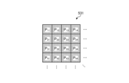
- FIG. 4 is a diagram illustrating a schematic configuration of a pixel unit according to an embodiment.
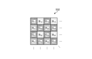
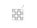
- FIG. 5 is a diagram illustrating a schematic configuration of a color filter according to an embodiment.
- FIG. 6 is a diagram illustrating the sensitivity and wavelength band of each filter according to one embodiment.
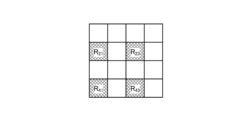
- FIG. 7A is a diagram illustrating signal values of R pixels of an image sensor according to one embodiment.
- FIG. 7B is a diagram illustrating signal values of G pixels of an image sensor according to one embodiment.
- FIG. 7C is a diagram illustrating a signal value of a B pixel of an image sensor according to one embodiment.
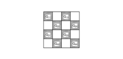
- FIG. 8 is a diagram illustrating a schematic configuration of a cut filter according to an embodiment.
- FIG. 9 is a diagram illustrating a transmission characteristic of a cut filter according to an embodiment.
- FIG. 10 is a flowchart showing an outline of the process executed by the control device according to the embodiment.
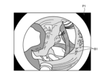
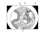
- FIG. 11 is a diagram illustrating an example of a white light image generated by a generating unit according to an embodiment.
- FIG. 12 is a diagram illustrating a detection result in which a detection unit according to one embodiment detects a blood vessel region in a white light image.
- FIG. 12 is a diagram illustrating a detection result in which a detection unit according to one embodiment detects a blood vessel region in a white light image.
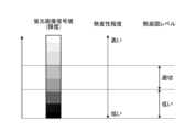
- FIG. 13 is a diagram showing a schematic diagram of the correspondence relationship between the signal value of a fluorescence image, the degree of thermal denaturation, and the thermal coagulation level of a blood vessel according to one embodiment.
- FIG. 14 is a diagram illustrating an example of a composite image generated by a composition unit according to an embodiment.
- FIG. 1 is a diagram showing a schematic configuration of an endoscope system according to an embodiment.
- the endoscope system 1 shown in FIG. 1 is used in the medical field and is a system for observing and treating biological tissue in a subject such as a living body.
- a rigid endoscope system using a rigid endoscope (insertion unit 2) shown in FIG. 1 will be described as the endoscope system 1, but the present invention is not limited to this, and may be an endoscope system equipped with a flexible endoscope, for example.
- the endoscope system 1 may be applied to a medical microscope or a medical surgery robot system that includes a medical imaging device that images a subject and performs surgery or processing while displaying an observation image based on an imaging signal (image data) captured by the medical imaging device on a display device.
- minimally invasive treatments using endoscopes, laparoscopes, etc. have become widespread in the medical field.
- endoscopic submucosal dissection (ESD), laparoscopy and endoscopic cooperative surgery (LECS), non-exposed endoscopic wall-inversion surgery (NEWS), transurethral resection of the bladder tumor (TUR-bt), etc. are widely performed as minimally invasive treatments using an endoscope and a laparoscope.
- ESD endoscopic submucosal dissection
- LECS laparoscopy and endoscopic cooperative surgery
- NEWS non-exposed endoscopic wall-inversion surgery
- TUR-bt transurethral resection of the bladder tumor
- a surgeon when performing treatment, for example, in order to mark the area to be operated on as a pretreatment, a surgeon such as a doctor performs a marking treatment by cauterization or heat treatment on a characteristic area (pathogenic area) having a lesion on the biological tissue using a treatment tool of an energy device that emits energy such as high frequency, ultrasound, or microwave.
- the surgeon also performs treatments such as ablation and coagulation of the biological tissue of the subject using an energy device, etc.
- the endoscope system 1 shown in Fig. 1 is used when performing surgery or treatment on a subject using a treatment tool (not shown) such as an energy device capable of thermal treatment.
- the endoscope system 1 shown in Fig. 1 is used for endoscopic submucosal dissection (ESD).
- the endoscope system 1 shown in FIG. 1 includes an insertion section 2, a light source device 3, a light guide 4, an endoscope camera head 5 (an endoscopic imaging device), a first transmission cable 6, a display device 7, a second transmission cable 8, a control device 9, a third transmission cable 10, a perfusion device 11, and a fourth transmission cable 12.
- the insertion section 2 is hard or at least partially soft and has an elongated shape.
- the insertion section 2 is inserted into a subject such as a patient via a trocar.
- the insertion section 2 is provided with an optical system such as a lens that forms an observation image inside.
- the light source device 3 is connected to one end of the light guide 4, and under the control of the control device 9, supplies illumination light to one end of the light guide 4 to be irradiated into the subject.
- the light source device 3 is realized using one or more light sources, such as an LED (Light Emitting Diode) light source, a xenon lamp, or a semiconductor laser element such as an LD (laser diode), a processor which is a processing device having hardware such as an FPGA (Field Programmable Gate Array) or a CPU (Central Processing Unit), and a memory which is a temporary storage area used by the processor.
- the light source device 3 and the control device 9 may be configured to communicate individually as shown in FIG. 1, or may be integrated.
- One end of the light guide 4 is detachably connected to the light source device 3, and the other end is detachably connected to the insertion section 2.
- the light guide 4 guides the illumination light supplied from the light source device 3 from one end to the other, and supplies it to the insertion section 2.
- the endoscopic camera head 5 is detachably connected to the eyepiece 21 of the insertion section 2. Under the control of the control device 9, the endoscopic camera head 5 receives the observation image formed by the insertion section 2 and performs photoelectric conversion to generate an imaging signal (RAW data), and outputs this imaging signal to the control device 9 via the first transmission cable 6.
- RAW data an imaging signal
- the first transmission cable 6 transmits the imaging signal output from the endoscopic camera head 5 to the control device 9, and also transmits setting data, power, etc. output from the control device 9 to the endoscopic camera head 5.
- the setting data refers to a control signal, synchronization signal, clock signal, etc. that controls the endoscopic camera head 5.
- the display device 7 displays an observation image based on an imaging signal that has been subjected to image processing in the control device 9, and various information related to the endoscope system 1.
- the display device 7 is realized using a display monitor such as a liquid crystal or organic EL (Electro Luminescence) display.
- the second transmission cable 8 transmits the imaging signal that has been subjected to image processing in the control device 9 to the display device 7.
- the control device 9 is realized using a processor, which is a processing device having hardware such as a GPU (Graphics Processing Unit), FPGA, or CPU, and a memory, which is a temporary storage area used by the processor.
- the control device 9 comprehensively controls the operation of the light source device 3, the endoscopic camera head 5, and the display device 7 via each of the first transmission cable 6, the second transmission cable 8, and the third transmission cable 10 according to a program recorded in the memory.
- the control device 9 also performs various image processing on the imaging signal input via the first transmission cable 6 and outputs the result to the second transmission cable 8.
- the third transmission cable 10 has one end detachably connected to the light source device 3 and the other end detachably connected to the control device 9.
- the third transmission cable 10 transmits control data from the control device 9 to the light source device 3.
- Fig. 2 is a block diagram showing the functional configuration of the main parts of the endoscope system 1.
- the insertion portion 2 has an optical system 22 and an illumination optical system 23.
- the optical system 22 forms an image of the subject by collecting light such as reflected light from the subject, return light from the subject, excitation light from the subject, and fluorescence emitted from a thermally denatured region that has been thermally denatured by a thermal treatment such as an energy device.
- the optical system 22 is realized using one or more lenses, etc.
- the illumination optical system 23 irradiates the subject with illumination light supplied from the light guide 4.
- the illumination optical system 23 is realized using one or more lenses, etc.
- the light source device 3 includes a condenser lens 30, a first light source unit 31, a third light source unit 33, and a light source control unit .
- the focusing lens 30 focuses the light emitted by each of the first light source unit 31 and the third light source unit 33 and emits the light to the light guide 4.
- the first light source unit 31 emits visible white light (normal light) under the control of the light source control unit 34, thereby supplying white light as illumination light to the light guide 4.
- the first light source unit 31 is configured using a collimator lens, a white LED lamp, a driving driver, etc.
- the first light source unit 31 may supply visible white light by simultaneously emitting light using a red LED lamp, a green LED lamp, and a blue LED lamp.
- the first light source unit 31 may also be configured using a halogen lamp, a xenon lamp, etc.
- the second light source unit 32 emits first narrowband light having a predetermined wavelength band under the control of the light source control unit 34, thereby supplying the first narrowband light as illumination light to the light guide 4.
- the first narrowband light has a wavelength band of 530 nm to 550 nm (with a central wavelength of 540 nm).
- the second light source unit 32 is configured using a green LED lamp, a collimating lens, a transmission filter that transmits light of 530 nm to 550 nm, a driver, etc.
- the third light source unit 33 emits a second narrowband light having a wavelength band different from that of the first narrowband light under the control of the light source control unit 34, thereby supplying the second narrowband light as illumination light to the light guide 4.
- the second narrowband light has a wavelength band of 400 nm to 430 nm (center wavelength 415 nm).
- the third light source unit 33 is realized using a collimating lens, a semiconductor laser such as a violet LD (laser diode), and a driving driver.
- the second narrowband light functions as an excitation light that excites advanced glycation end products generated by applying heat treatment to biological tissue by an energy device or the like.
- AGEs are characterized by the inclusion of substances with fluorescent properties.
- AGEs are generated by heating amino acids and reducing sugars in the biological tissue, which causes the Maillard reaction.
- the AGEs generated by this heating can be visualized in the state of heat treatment by fluorescent observation.
- AGEs emit stronger fluorescence than the autofluorescent substances that are originally present in biological tissue.
- the fluorescent properties of AGEs generated in biological tissue by heat treatment with an energy device or the like are utilized to visualize the thermally denatured region caused by the heat treatment.
- the biological tissue is irradiated with blue excitation light with a wavelength of about 415 nm from the third light source unit 33 to excite AGEs.
- a fluorescent image thermalally denatured image
- an image signal capturing the fluorescence (e.g., green light with a wavelength of 490 to 625 nm) emitted from the thermally denatured region generated by AGEs.
- the light source control unit 34 is realized using a processor having hardware such as an FPGA or a CPU, and a memory that is a temporary storage area used by the processor.
- the light source control unit 34 controls the light emission timing and light emission time of each of the first light source unit 31 and the third light source unit 33 based on control data input from the control device 9.
- Fig. 3 is a diagram showing a schematic diagram of the wavelength characteristics of the light emitted by each of the second light source unit 32 and the third light source unit 33.
- the horizontal axis indicates the wavelength (nm), and the vertical axis indicates the wavelength characteristics.
- the broken line L NG indicates the wavelength characteristics of the first narrowband light emitted by the second light source unit 32
- the broken line L V indicates the wavelength characteristics of the second narrowband light (excitation light) emitted by the third light source unit 33.
- the curve L B indicates the blue wavelength band
- the curve L G indicates the green wavelength band
- the curve L R indicates the red wavelength band.
- the second light source unit 32 emits narrowband light having a center wavelength (peak wavelength) of 540 nm and a wavelength band of 530 nm to 550 nm
- the third light source unit 33 emits excitation light having a center wavelength (peak wavelength) of 415 nm and a wavelength band of 400 nm to 430 nm.
- the second light source unit 32 and the third light source unit 33 each emit a first narrowband light and a second narrowband light (excitation light) of mutually different wavelength bands.
- the first narrowband light is used for layer discrimination in biological tissue. Specifically, the first narrowband light increases the difference between the absorbance of the mucosal layer, which is the subject, and the absorbance of the muscle layer, which is the subject, to a degree that makes it possible to distinguish the two subjects. For this reason, in the second image for layer discrimination acquired by irradiating the first narrowband light for layer discrimination, the area in which the mucosal layer is imaged has a smaller pixel value (brightness value) and is darker than the area in which the muscle layer is imaged. That is, in one embodiment 1, by using the second image for layer discrimination to generate a display image, it is possible to achieve a display mode in which the mucosal layer and the muscle layer can be easily distinguished.
- the second narrowband light is light for layer discrimination in biological tissue that is different from the first narrowband light.
- the second narrowband light increases the difference in absorbance between the muscle layer, which is the subject, and the fat layer, which is the subject, to a degree that makes it possible to distinguish between the two subjects. Therefore, in the second light image for layer discrimination obtained by irradiating the second narrowband light for layer discrimination, the area in which the muscle layer is imaged has a smaller pixel value (brightness value) and is darker than the area in which the fat layer is imaged. In other words, by using the second image for layer discrimination to generate a display image, it becomes possible to easily distinguish between the muscle layer and the fat layer.
- Both the mucosal layer (biological mucosa) and the muscular layer are subjects that contain a large amount of myoglobin.
- the concentration of myoglobin contained is relatively high in the mucosal layer and relatively low in the muscular layer.
- the difference in the absorption characteristics between the mucosal layer and the muscular layer is caused by the difference in the concentration of myoglobin contained in each of the mucosal layer (biological mucosa) and the muscular layer.
- the difference in absorbance between the mucosal layer and the muscular layer is greatest near the wavelength at which the absorbance of the biological mucosa is at its maximum.
- the first narrowband light for layer discrimination is light that shows a greater difference between the mucosal layer and the muscular layer than light that has a peak wavelength in another wavelength band.
- the second narrowband light has a lower absorbance in fat than in muscle layer
- the pixel value (brightness value) of the area in which the muscle layer is imaged is smaller than the pixel value (brightness value) of the area in which the fat layer is imaged.
- the second narrowband light for layer discrimination is light corresponding to a wavelength at which the absorbance of the muscle layer is at a maximum value, it is light in which the difference between the muscle layer and fat layer appears large. In other words, the difference between the pixel value (brightness value) of the muscle layer area and the pixel value (brightness value) of the fat layer area in the second image for layer discrimination becomes large enough to be distinguished.
- the light source device 3 irradiates the biological tissue with each of the first narrowband light and the second narrowband light.
- the endoscopic camera head 5 which will be described later, can identify each of the mucosal layer, muscle layer, and fat layer that make up the biological tissue by capturing an image of the return light from the biological tissue, and can obtain an image in which the blood vessel region can be identified.
- the endoscopic camera head 5 includes an optical system 51, a drive unit 52, an image sensor 53, a cut filter 54, an A/D conversion unit 55, a P/S conversion unit 56, an image capture recording unit 57, and an image capture control unit 58.
- the optical system 51 forms an image of the subject collected by the optical system 22 of the insertion part 2 on the light receiving surface of the image sensor 53.
- the optical system 51 is capable of changing the focal length and focal position.
- the optical system 51 is configured using a plurality of lenses 511.
- the optical system 51 changes the focal length and focal position by moving each of the plurality of lenses 511 on the optical axis L1 using the drive part 52.
- the driving unit 52 moves the multiple lenses 511 of the optical system 51 along the optical axis L1 under the control of the imaging control unit 58.
- the driving unit 52 is configured using a motor such as a stepping motor, a DC motor, or a voice coil motor, and a transmission mechanism such as a gear that transmits the rotation of the motor to the optical system 51.
- the imaging element 53 is realized by using a CCD (Charge Coupled Device) or CMOS (Complementary Metal Oxide Semiconductor) image sensor having multiple pixels arranged in a two-dimensional matrix. Under the control of the imaging control unit 58, the imaging element 53 receives the subject image (light rays) formed by the optical system 51 through the cut filter 54, performs photoelectric conversion to generate an imaging signal (RAW data), and outputs it to the A/D conversion unit 55.
- the imaging element 53 has a pixel unit 531 and a color filter 532.
- Fig. 4 is a diagram showing a schematic configuration of the pixel unit 531.
- the imaging control unit 58 the pixel unit 531 reads out image signals as image data from pixels Pnm in a readout region arbitrarily set as a readout target among the plurality of pixels Pnm , and outputs the image signals to the A/D conversion unit 55.
- FIG. 5 is a diagram showing a schematic configuration of color filter 532.
- color filter 532 is configured in a Bayer array with 2 ⁇ 2 as one unit.
- Color filter 532 is configured using a filter R that transmits light in the red wavelength band, two filters G that transmit light in the green wavelength band, and a filter B that transmits light in the blue wavelength band.
- Fig. 6 is a diagram showing the sensitivity and wavelength band of each filter.
- the horizontal axis indicates wavelength (nm) and the vertical axis indicates transmission characteristics (sensitivity characteristics).
- the curve L- B indicates the transmission characteristics of filter B
- the curve L- G indicates the transmission characteristics of filter G
- the curve L- R indicates the transmission characteristics of filter R.
- the filter B transmits light in the blue wavelength band.
- the filter G transmits light in the green wavelength band.
- the filter R transmits light in the red wavelength band.
- the pixel P- nm having the filter R disposed on the light receiving surface is referred to as the R pixel
- the pixel P -nm having the filter G disposed on the light receiving surface is referred to as the G pixel
- the pixel P -nm having the filter B disposed on the light receiving surface is referred to as the B pixel.
- the image sensor 53 configured in this manner receives the subject image formed by the optical system 51, it generates color signals (R signal, G signal, and B signal) for the R pixel, G pixel, and B pixel, respectively, as shown in Figures 7A to 7C.
- the cut filter 54 is disposed on the optical axis L1 between the optical system 51 and the image sensor 53.
- the cut filter 54 is provided on the light receiving surface side (incident surface side) of the G pixel provided with the filter G that transmits at least the green wavelength band of the color filter 532.
- the cut filter 54 blocks light in a short wavelength band including the wavelength band of the excitation light and transmits a wavelength band longer than the wavelength band of the excitation light.
- Fig. 8 is a diagram showing a schematic configuration of the cut filter 54. As shown in Fig. 8, the filter F11 constituting the cut filter 54 is disposed at the position where the filter G11 (see Fig. 5) is disposed, on the light receiving surface side directly above the filter G11 .
- Fig. 9 is a diagram showing a schematic diagram of the transmission characteristic of the cut filter 54.
- the horizontal axis represents wavelength (nm) and the vertical axis represents the transmission characteristic.
- the broken line L F represents the transmission characteristic of the cut filter 54
- the broken line L NG represents the wavelength characteristic of the fluorescent light
- the broken line L V represents the wavelength characteristic of the excitation light.
- the cut filter 54 blocks the wavelength band of the excitation light and transmits the wavelength band on the longer wavelength side of the wavelength band of the excitation light. Specifically, the cut filter 54 blocks light in the wavelength band on the shorter wavelength side of 400 nm to less than 430 nm, which includes the wavelength band of the excitation light, and transmits light in the wavelength band on the longer wavelength side of 400 nm to 430 nm, which includes the excitation light.
- the A/D conversion unit 55 under the control of the imaging control unit 58, performs A/D conversion processing on the analog imaging signal input from the imaging element 53 and outputs the result to the P/S conversion unit 56.
- the A/D conversion unit 55 is realized using an A/D conversion circuit or the like.
- the P/S conversion unit 56 performs parallel/serial conversion on the digital imaging signal input from the A/D conversion unit 55 under the control of the imaging control unit 58, and outputs the parallel/serial converted imaging signal to the control device 9 via the first transmission cable 6.
- the P/S conversion unit 56 is realized using a P/S conversion circuit or the like. Note that in one embodiment, instead of the P/S conversion unit 56, an E/O conversion unit that converts the imaging signal into an optical signal may be provided, and the imaging signal may be output to the control device 9 by the optical signal, or the imaging signal may be transmitted to the control device 9 by wireless communication such as Wi-Fi (Wireless Fidelity) (registered trademark).
- Wi-Fi Wireless Fidelity
- the imaging and recording unit 57 records various information related to the endoscopic camera head 5 (e.g., pixel information of the imaging element 53, characteristics of the cut filter 54).
- the imaging and recording unit 57 also records various setting data and control parameters transmitted from the control device 9 via the first transmission cable 6.
- the imaging and recording unit 57 is configured using a non-volatile memory and a volatile memory.
- the imaging control unit 58 controls the operation of each of the drive unit 52, the imaging element 53, the A/D conversion unit 55, and the P/S conversion unit 56 based on the setting data received from the control device 9 via the first transmission cable 6.
- the imaging control unit 58 is realized using a TG (Timing Generator), a processor having hardware such as an ASIC (Application Specific Integrated Circuit) or a CPU, and a memory that is a temporary storage area used by the processor.
- the control device 9 includes an S/P conversion unit 91 , an image processing unit 92 , an input unit 93 , a recording unit 94 , and a control unit 95 .
- the S/P conversion unit 91 Under the control of the control unit 95, the S/P conversion unit 91 performs serial/parallel conversion on the image data received from the endoscopic camera head 5 via the first transmission cable 6 and outputs the converted data to the image processing unit 92. If the endoscopic camera head 5 outputs an imaging signal as an optical signal, the S/P conversion unit 91 may be replaced by an O/E conversion unit that converts the optical signal into an electrical signal. If the endoscopic camera head 5 transmits an imaging signal via wireless communication, the S/P conversion unit 91 may be replaced by a communication module capable of receiving wireless signals.
- the image processing unit 92 Under the control of the control unit 95, the image processing unit 92 performs a predetermined image processing on the imaging signal of the parallel data input from the S/P conversion unit 91 and outputs the result to the display device 7.
- the predetermined image processing includes demosaic processing, white balance processing, gain adjustment processing, gamma correction processing, and format conversion processing.
- the image processing unit 92 is realized using a processor, which is a processing device having hardware such as a GPU or FPGA, and a memory, which is a temporary storage area used by the processor.
- the image processing unit 92 has an acquisition unit 921, a generation unit 922, a detection unit 923, an identification unit 924, a synthesis unit 925, and a display control unit 926.
- the acquisition unit 921 acquires an imaging signal generated by the endoscopic camera head 5 capturing an image via the insertion unit 2. Specifically, the acquisition unit 921 acquires from the endoscopic camera head 5, via the S/P conversion unit 91, an imaging signal generated by the imaging element 53 of the endoscopic camera head 5 capturing an image when the light source device 3 irradiates the biological tissue with white light, narrowband light, or excitation light.
- the generating unit 922 generates a white light image, a special light image for blood vessel recognition, and a fluorescent image based on the imaging signal acquired by the acquiring unit 921. Specifically, the generating unit 922 performs demosaic processing, white balance processing, gain adjustment processing, gamma correction processing, and the like on the imaging signal acquired by the acquiring unit 921 to generate a white image. More specifically, when the light source device 3 irradiates white light toward living tissue, the generating unit 922 performs demosaic processing, and the like on the imaging signal acquired by the acquiring unit 921 to generate a white light image.
- the generating unit 922 performs image processing on the signal values of the G pixels and B pixels included in the imaging signal acquired by the acquiring unit 921 to generate an image for blood vessel recognition, which is a pseudo-color image (a narrowband image that is one of the special light images). Furthermore, when the light source device 3 irradiates excitation light toward living tissue, the generating unit 922 performs demosaic processing, and the like on the imaging signal acquired by the acquiring unit 921 to generate a fluorescent image.
- the detection unit 923 detects the blood vessel region in the white light image based on the white light image and the blood vessel recognition image generated by the generation unit 922. Specifically, the detection unit 923 detects the blood vessel region in the white light image based on the feature amount of the blood vessel recognition image generated by the generation unit 922. For example, the detection unit 923 performs a binarization process or edge extraction process, etc., of a well-known technology, on the blood vessel recognition image to extract feature amounts, and detects the blood vessel region in the white light image based on the extracted feature amounts.
- the detection unit 923 detects the blood vessel region in the white light image by performing a binarization process, etc., based on the feature amount of the blood vessel recognition image, but is not limited to this, and the blood vessel region in the white image may be detected using a trained model that has trained multiple blood vessel recognition images by machine learning such as deep learning.
- the trained model learns, as input parameters, a plurality of images for blood vessel recognition and training data (learning data) that includes annotations such as pixel addresses that specify the positions of blood vessel regions included in each of the plurality of images for blood vessel recognition, and detects and outputs the position of the blood vessel region in the white light image as an output parameter (learning result). That is, the detection unit 923 may be configured to input the white light image and the image for blood vessel recognition as input parameters using the trained model described above, and output the position of the blood vessel region in the white light image as an output parameter.
- the identification unit 924 identifies thermal denaturation information in the blood vessel region of the white light image based on the blood vessel region of the white light image detected by the detection unit 923 and the fluorescence image generated by the generation unit 922. Specifically, the identification unit 924 identifies thermal denaturation information based on the signal values of each pixel in the region of the fluorescence image that corresponds to the blood vessel region of the white light image.
- the synthesis unit 925 generates a synthesis image by synthesizing the thermal denaturation information identified by the identification unit 924 with the blood vessel region of the white light image detected by the detection unit 923.
- the display control unit 926 Under the control of the control unit 96, the display control unit 926 outputs various information related to the endoscope system 1 to the display device 7. The display control unit 926 also outputs the composite image generated by the composition unit 925 to the display device 7.
- the input unit 93 receives inputs of various operations related to the endoscope system 1 and outputs the received operations to the control unit 95.
- the input unit 93 is configured using a mouse, a foot switch, a keyboard, buttons, switches, a touch panel, etc.
- the recording unit 94 is realized using a recording medium such as a volatile memory, a non-volatile memory, an SSD (Solid State Drive), an HDD (Hard Disk Drive), a memory card, etc.
- the recording unit 94 records data including various parameters necessary for the operation of the endoscope system 1.
- the recording unit 94 also has a program recording unit 941 that records various programs for operating the endoscope system 1.
- the control unit 95 is realized using a processor having hardware such as an FPGA or CPU, and a memory that is a temporary storage area used by the processor.
- the control unit 95 comprehensively controls each component that constitutes the endoscope system 1. Specifically, the control unit 95 reads out a program recorded in the program recording unit 941 into the working area of the memory and executes it, and controls each component through the execution of the program by the processor, thereby allowing the hardware and software to work together to realize a functional module that meets a specified purpose.
- FIG 10 is a flow chart showing an outline of the process executed by the control device 9.
- control unit 96 causes the first light source unit 31 of the light source device 3 to emit light and supply white light to the insertion unit 2, thereby irradiating the white light toward the biological tissue (step S101).
- control unit 96 causes the imaging element 53 of the endoscopic camera head 5 to capture images of the return light from the biological tissue and the reflected light from the biological tissue (step S102).
- the acquisition unit 921 acquires the imaging signal generated by the imaging element 53 of the endoscopic camera head 5 (step S103).
- FIG. 11 is a diagram showing an example of a white light image generated by the generating unit 922.
- the generating unit 922 performs demosaic processing, white balance processing, gain adjustment processing, gamma correction processing, etc. on the imaging signal acquired by the acquiring unit 921 to generate a white light image P1 including a vascular region B1 of blood vessels in the biological tissue within the subject.
- control unit 96 causes each of the second light source unit 32 and the third light source unit 33 of the light source device 3 to emit light and supply narrowband light (first narrowband light and second narrowband light) to the insertion unit 2, thereby irradiating narrowband light for recognizing blood vessels in biological tissue (step S105).
- control unit 96 causes the imaging element 53 of the endoscopic camera head 5 to capture images of the return light from the biological tissue and the reflected light from the biological tissue (step S106).
- the acquisition unit 921 acquires an imaging signal from the imaging element 53 of the endoscopic camera head 5 (step S107).
- the generating unit 922 generates an image for blood vessel recognition based on the imaging signal acquired by the acquiring unit 921 (step S108). Specifically, the generating unit 922 performs image processing on the signal values of each of the G pixels and B pixels included in the imaging signal acquired by the acquiring unit 921 to generate an image for blood vessel recognition, which is a pseudo-color image (narrowband image).
- the signal value of the G pixel includes information on the mucous membrane deep layer of the subject.
- the signal value of the B pixel includes information on the mucous membrane surface layer of the subject.
- the generating unit 922 performs image processing such as gain control processing, pixel complementation processing, and mucous membrane enhancement processing on the signal values of each of the G pixels and B pixels included in the imaging signal to generate an image for blood vessel recognition, which is a pseudo-color image.
- the image for blood vessel recognition is an image generated using only the signal values of the G pixels and the B pixels.
- the generating unit 922 deletes the signal values of the R pixels included in the imaging signal acquired by the acquiring unit 921 without using them in generating the image for blood vessel recognition.
- FIG. 12 is a diagram showing a schematic diagram of the detection result of the detection unit 923 detecting the blood vessel region in the white light image.
- the detection unit 923 detects the blood vessel region B1 in the white light image P1 based on the feature amount of the blood vessel recognition image generated by the generation unit 922.
- the detection unit 923 performs a binarization process or an edge extraction process using a well-known technique on the blood vessel recognition image to extract the feature amount, and detects the blood vessel region B1 in the white light image P1 based on the extracted feature amount.
- the detection unit 923 detects the region of the pixel address of the white light image P1 corresponding to the pixel address of the blood vessel region B1 detected in the blood vessel recognition image as the blood vessel region B1 of the white light image P1.
- control unit 96 causes the third light source unit 33 of the light source device 3 to emit light and supply excitation light to the insertion unit 2, thereby irradiating the biological tissue with excitation light to cause the thermally denatured area to emit light (step S110).
- control unit 96 causes the imaging element 53 of the endoscopic camera head 5 to capture an image of the light emitted from the biological tissue (step S111).
- the acquisition unit 921 acquires an imaging signal from the imaging element 53 of the endoscopic camera head 5 (step S112).
- the generating unit 922 generates a fluorescent image based on the imaging signal acquired by the acquiring unit 921 (step S113).
- the identification unit 924 identifies thermal denaturation information in the vascular region of the white light image based on the vascular region B1 of the white light image P1 detected by the detection unit 923 and the fluorescent image generated by the generation unit 922 (step S114). Specifically, the identification unit 924 identifies thermal denaturation information based on the signal values of each pixel in the region of the fluorescent image corresponding to the vascular region B1 of the white light image P1.
- the identification unit 924 identifies an area with a low level of thermal coagulation as thermal denaturation information based on the signal value of each pixel in the area of the fluorescence image corresponding to the blood vessel region B1 of the white light image P1. Specifically, the identification unit 924 determines whether the signal value is smaller than a predetermined value for each pixel in the area of the fluorescence image corresponding to the blood vessel region B1 of the white light image P1.
- the identification unit 924 then identifies the area of pixels whose signal value is smaller than the predetermined value in the area of the fluorescence image corresponding to the blood vessel region B1 of the white light image P1 as an area with a low level of thermal coagulation. In contrast, the identification unit 924 identifies the area of pixels whose signal value is not smaller than the predetermined value in the area of the fluorescence image corresponding to the blood vessel region B1 of the white light image P1, that is, the area of pixels whose signal value is equal to or greater than the predetermined value, as an area with a high level of thermal coagulation.
- the synthesis unit 925 generates a synthetic image by synthesizing the thermal denaturation information identified by the identification unit 924 with the blood vessel region B1 of the white light image P1 detected by the detection unit 923 (step S115).
- FIG. 14 is a diagram showing an example of a synthetic image generated by the synthesis unit 925.
- the synthesis unit 925 generates a synthetic image P2 by synthesizing the thermal denaturation information D1, D2 identified by the identification unit 924 with the blood vessel region B1 of the white light image P1 detected by the detection unit 923.
- the synthesis unit 925 synthesizes the contour of the blood vessel region B1 of the white light image P1 detected by the detection unit 923 with the synthetic image P2.
- the thermal denaturation information D1 is a region where the thermal coagulation level is higher than a predetermined value as determined by the identification unit 924. Furthermore, the thermal denaturation information D2 is a region where the thermal coagulation level is lower than a predetermined value as determined by the identification unit 924.
- the thermal denaturation information D1 and D2 are represented by different hatching to distinguish them from each other. That is, the synthesis unit 925 synthesizes the thermal denaturation information D1 and the thermal denaturation information D2 in different colors so that they can be distinguished in the blood vessel region B1 of the white light image P1 detected by the detection unit 923, thereby generating a synthetic image P2.
- the display control unit 926 outputs the composite image P2 generated by the composition unit 925 to the display device 7 (step S116). This allows the surgeon to intuitively grasp the thermal coagulation level of the vascular region B1 without relying on his or her own empirical rules.
- control unit 96 determines whether or not an end signal to end the observation of the subject by the endoscopic system 1 has been input from the input unit 93 (step S117). If the control unit 96 determines that an end signal to end the observation of the subject by the endoscopic system 1 has been input from the input unit 93 (step S117: Yes), the endoscopic system 1 ends this process. On the other hand, if the control unit 96 determines that an end signal to end the observation of the subject by the endoscopic system 1 has not been input from the input unit 93 (step S117: No), the endoscopic system 1 returns to the above-mentioned step S101.
- the display control unit 926 outputs the thermal denaturation information of the blood vessel region B1 of the white light image P1 identified by the identification unit 924 to the display device 7, so that the surgeon can grasp the state of coagulation denaturation in the blood vessel.
- the display control unit 926 outputs the composite image P2 generated by the composition unit 925 to the display device 7, allowing the surgeon to intuitively grasp the state of coagulation degeneration in the blood vessels.
- the identification unit 924 identifies thermal alteration information based on the signal values of each pixel that constitutes the fluorescent image, making it possible to accurately identify the area in which thermal alteration is occurring.
- the identification unit 924 identifies pixel regions in the region of the fluorescence image corresponding to the vascular region B1 of the white light image P1, in which the signal value is smaller than a predetermined value, as regions with a low level of thermal coagulation, making it possible to distinguish and identify regions with a high level of thermal coagulation from regions with a low level of thermal coagulation.
- the identification unit 924 identifies the thermal coagulation level in the vascular region B1 of the white light image P1, so that the state of thermal denaturation for the vascular region most desired by the surgeon can be presented.
- the display control unit 926 may superimpose the thermal denaturation information on the blood vessel region B1 of the white light image P1 identified by the identification unit 924 and output the information to the display device 7.
- the detection unit 923 may identify a blood vessel region from a feature amount of the white light image generated by the generation unit 922. For example, the detection unit 923 may extract a feature amount by performing a binarization process or an edge extraction process using a well-known technique on a specific component of the white light image, such as the signal value of a G pixel, and detect a blood vessel region in the white light image based on the extracted feature amount.
- narrowband imaging is used as the special light observation, in which narrowband light including a first narrowband light (530 nm to 550 nm) and a second narrowband light (400 nm to 430 nm) is irradiated onto biological tissue.
- red light observation RDI: Red Dichromatic Imaging
- the detection unit 923 detects the blood vessel area from the blood vessel recognition image of the red light observation image. This makes it possible to easily detect blood vessels in deep areas such as mucous membranes.
- Various inventions can be formed by appropriately combining a plurality of components disclosed in the endoscope system according to the embodiment of the present disclosure described above. For example, some components may be deleted from all the components described in the endoscope system according to the embodiment of the present disclosure described above. Furthermore, the components described in the endoscope system according to the embodiment of the present disclosure described above may be appropriately combined.
- the components are connected to each other by wires, but they may be connected wirelessly via a network.
- the functions of the image processing unit 92 provided in the endoscope system i.e., the functional modules of the acquisition unit 921, generation unit 922, detection unit 923, identification unit 924, synthesis unit 925, and display control unit 926, may be provided in a server or the like that can be connected via a network.
- a server may be provided for each functional module.
- transurethral bladder tumor resection an example of use in transurethral bladder tumor resection has been described, but the present disclosure is not limited to this, and can be applied to various procedures, such as resecting lesions using an energy device, etc.
- the "unit” described above can be read as “means” or “circuit.”
- the control unit can be read as control means or control circuit.
Landscapes
- Health & Medical Sciences (AREA)
- Life Sciences & Earth Sciences (AREA)
- Surgery (AREA)
- Engineering & Computer Science (AREA)
- General Health & Medical Sciences (AREA)
- Nuclear Medicine, Radiotherapy & Molecular Imaging (AREA)
- Medical Informatics (AREA)
- Physics & Mathematics (AREA)
- Radiology & Medical Imaging (AREA)
- Pathology (AREA)
- Public Health (AREA)
- Heart & Thoracic Surgery (AREA)
- Optics & Photonics (AREA)
- Molecular Biology (AREA)
- Animal Behavior & Ethology (AREA)
- Biophysics (AREA)
- Biomedical Technology (AREA)
- Veterinary Medicine (AREA)
- Signal Processing (AREA)
- Quality & Reliability (AREA)
- Computer Vision & Pattern Recognition (AREA)
- General Physics & Mathematics (AREA)
- Theoretical Computer Science (AREA)
- Endoscopes (AREA)
Abstract
Description
図1は、一実施の形態に係る内視鏡システムの概略構成を示す図である。図1に示す内視鏡システム1は、医療分野に用いられ、生体等の被検体内の生体組織を観察および処置するシステムである。なお、一実施の形態では、内視鏡システム1として、図1に示す硬性鏡(挿入部2)を用いた硬性内視鏡システムについて説明するが、これに限定されることなく、例えば軟性の内視鏡を備えた内視鏡システムであってもよい。さらに、内視鏡システム1として、被検体を撮像する医療用撮像装置を備え、この医療用撮像装置によって撮像された撮像信号(画像データ)に基づく観察画像を表示装置に表示させながら手術や処理等を行う医療用顕微鏡または医療用手術ロボットシステム等のものであっても適用することができる。また、近年、医療分野では、内視鏡および腹腔鏡等を用いた低侵襲治療が広く行われるようになっている。例えば、内視鏡および腹腔鏡等を用いた低侵襲治療としては、内視鏡的粘膜下層剥離術(ESD:Endoscopic Submucosal Dissection)、腹腔鏡内視鏡合同胃局所切除術(LECS:Laparoscopy and Endoscopy Cooperative Surgery)、非穿孔式内視鏡的胃壁内反切除術(NEWS:Non-exposed Endoscopic Wall-inversion Surgery)、経尿道的膀胱腫瘍切除術(TUR―bt:transurethral resection of the bladder tumor)等が広く行われている。これらの低侵襲治療では、処置を行う場合、例えば、前処置として手術対象領域のマーキング等のために、医者等の術者が高周波、超音波、マイクロ波等のエネルギーを発するエネルギーデバイスの処置具を用いて生体組織に対して病変部を有する特徴領域(病原領域)に対して焼灼による切除や熱処置によるマーキング処置等を行う。また、術者は、実際の処置の場合にも、エネルギーデバイス等を用いて被検体の生体組織の切除および凝固等の処置を行う。このため、図1に示す内視鏡システム1は、熱処置が可能なエネルギーデバイス等の処置具(図示せず)を用いて被検体の手術または処理を行う際に用いられる。具体的には、図1に示す内視鏡システム1は、内視鏡的粘膜下層剥離術(ESD)に用いられる。
次に、上述した内視鏡システム1の要部の機能構成について説明する。図2は、内視鏡システム1の要部の機能構成を示すブロック図である。
まず、挿入部2の構成について説明する。挿入部2は、光学系22と、照明光学系23と、を有する。
次に、光源装置3の構成について説明する。光源装置3は、集光レンズ30と、第1の光源部31と、第3の光源部33と、光源制御部34と、を備える。
図2に戻り、内視鏡システム1の構成の説明を続ける。
次に、内視鏡カメラヘッド5の構成について説明する。内視鏡カメラヘッド5は、光学系51と、駆動部52と、撮像素子53と、カットフィルタ54と、A/D変換部55と、P/S変換部56と、撮像記録部57と、撮像制御部58と、を備える。
カットフィルタ54は、光学系51と撮像素子53との光軸L1上に配置される。カットフィルタ54は、少なくともカラーフィルタ532の緑色の波長帯域を透過するフィルタGが設けられたG画素の受光面側(入射面側)に設けられる。カットフィルタ54は、励起光の波長帯域を含む短波長の波長帯域の光を遮光し、励起光の波長帯域より長波長側の波長帯域を透過する。
A/D変換部55は、撮像制御部58による制御のもと、撮像素子53から入力されたアナログの撮像信号に対してA/D変換処理を行ってP/S変換部56へ出力する。A/D変換部55は、A/D変換回路等を用いて実現される。
次に、制御装置9の構成について説明する。
制御装置9は、S/P変換部91と、画像処理部92と、入力部93と、記録部94と、制御部95と、を備える。
次に、制御装置9が実行する処理について説明する。図10は、制御装置9が実行する処理の概要を示すフローチャートである。
上述した本開示の一実施の形態に係る内視鏡システムに開示されている複数の構成要素を適宜組み合わせることによって、種々の発明を形成することができる。例えば、上述した本開示の一実施の形態に係る内視鏡システムに記載した全構成要素からいくつかの構成要素を削除してもよい。さらに、上述した本開示の一実施の形態に係る内視鏡システムで説明した構成要素を適宜組み合わせてもよい。
2 挿入部
3 光源装置
4 ライトガイド
5 内視鏡カメラヘッド
6 第1の伝送ケーブル
7 表示装置
8 第2の伝送ケーブル
9 制御装置
10 第3の伝送ケーブル
11 医療用装置
12 第4の伝送ケーブル
21 接眼部
22 光学系
23 照明光学系
30 集光レンズ
31 第1の光源部
32 第2の光源部
33 光源制御部
51 光学系
52 駆動部
53 撮像素子
54 カットフィルタ
55 A/D変換部
56 P/S変換部
57 撮像記録部
58 撮像制御部
61 ビデオコネクタ
62 カメラヘッドコネクタ
91 S/P変換部
92 画像処理部
93 入力部
94 記録部
95 出力部
96 制御部
111 通信I/F
113a プログラム記録部
511 レンズ
531 画素部
532 カラーフィルタ
921 取得部
922 生成部
923 検出部
924 特定部
925 合成部
926 表示制御部
Claims (20)
- プロセッサを備える医療用装置であって、
前記プロセッサは、
被検体における血管の血管領域が特定された表示用画像と、少なくとも前記表示用画像の視野領域の一部と重なる蛍光画像と、を取得し、
前記表示用画像と、前記蛍光画像と、に基づいて、前記血管領域における熱変性情報を特定し、
前記熱変性情報を出力する、
医療用装置。 - 請求項1に記載の医療用装置であって、
前記プロセッサは、
前記表示用画像の前記血管領域に、前記熱変性情報を合成した合成画像を生成し、
前記合成画像を出力する、
医療用装置。 - 請求項1に記載の医療用装置であって、
前記プロセッサは、
前記表示用画像の前記血管領域に、前記熱変性情報を重畳して出力する、
医療用装置。 - 請求項1に記載の医療用装置であって、
前記プロセッサは、
熱変性領域から発せられる蛍光を撮像した撮像信号を取得し、
前記撮像信号に基づいて、前記蛍光画像を生成する、
医療用装置。 - 請求項4に記載の医療用装置であって、
前記蛍光は、
生体組織に熱処置を施すことによって生じる終末糖化産物から発せられる、
医療用装置。 - 請求項1に記載の医療用装置であって、
前記プロセッサは、
前記蛍光画像を構成する各画素の信号値に基づいて、前記熱変性情報を特定する、
医療用装置。 - 請求項6に記載の医療用装置であって、
前記プロセッサは、
前記蛍光画像を構成する各画素の信号値に基づいて、前記熱変性情報として熱凝固レベルが低い領域を特定する、
医療用装置。 - 請求項7に記載の医療用装置であって、
前記プロセッサは、
前記蛍光画像を構成する画素毎に、前記信号値が所定値より小さいか否かを判定し、
前記信号値が所定値より小さい画素の領域を、前記熱凝固レベルが低い領域として特定する、
医療用装置。 - 請求項8に記載の医療用装置であって、
前記プロセッサは、
前記血管領域における前記熱凝固レベルを特定する、
医療用装置。 - 請求項9に記載の医療用装置であって、
前記プロセッサは、
前記熱凝固レベルが所定値より低い領域を、前記熱凝固レベルが所定値以上の高い領域と比して識別可能に出力する、
医療用装置。 - 請求項1に記載の医療用装置であって、
前記表示用画像は、
白色光画像における特徴量から前記血管領域が特定された画像である、
医療用装置。 - 請求項1に記載の医療用装置であって、
前記表示用画像は、
特殊光画像における特徴量から前記血管領域が特定された画像である、
医療用装置。 - 請求項1に記載の医療用装置であって、
前記プロセッサは、
白色光画像と、前記白色光画像と同じ視野領域の血管認識用画像と、に基づいて、前記表示用画像を生成する、
医療用装置。 - 請求項1に記載の医療用装置であって、
前記プロセッサは、
血管認識用画像を取得し、
前記血管認識用画像から特定された血管領域を、白色光画像に重畳して前記表示用画像を生成する、
医療用装置。 - 請求項14に記載の医療用装置であって、
前記血管認識用画像は、
血液の吸光度に基づいて決定された狭帯域光により取得された画像である、
医療用装置。 - 請求項15に記載の医療用装置であって、
前記血管認識用画像は、
狭帯域光観察画像である、
医療用装置。 - 請求項15に記載の医療用装置であって、
前記血管認識用画像は、
赤色光観察画像である、
医療用装置。 - 光源装置と、撮像装置と、医療用装置と、を備える医療用システムであって、
前記光源装置は、
生体組織に熱処置を施すことによって生じる終末糖化産物を励起させる励起光を発光する光源を有し、
前記撮像装置は、
前記励起光によって発光する蛍光を撮像することによって撮像信号を生成する撮像素子を有し、
前記医療用装置は、
プロセッサを有し、
前記プロセッサは、
前記撮像素子から、被検体における血管の血管領域が特定された表示用画像と、少なくとも前記表示用画像の視野領域の一部と重なる蛍光画像と、を取得し、
前記表示用画像と、前記蛍光画像と、に基づいて、前記血管領域における熱変性情報を特定し、
前記熱変性情報を出力する、
医療用システム。 - プロセッサを備える医療用装置の作動方法であって、
前記プロセッサが、
被検体における血管の血管領域が特定された表示用画像と、少なくとも前記表示用画像の視野領域の一部と重なる蛍光画像と、を取得し、
前記表示用画像と、前記蛍光画像と、に基づいて、前記血管領域における熱変性情報を特定し、
前記熱変性情報を出力する、
医療用装置の作動方法。 - プロセッサを備える医療用装置が実行するプログラムであって、
前記プロセッサに、
被検体における血管の血管領域が特定された表示用画像と、少なくとも前記表示用画像の視野領域の一部と重なる蛍光画像と、を取得し、
前記表示用画像と、前記蛍光画像と、に基づいて、前記血管領域における熱変性情報を特定し、
前記熱変性情報を出力する、
ことを実行させる、
プログラム。
Priority Applications (3)
| Application Number | Priority Date | Filing Date | Title |
|---|---|---|---|
| CN202380093397.0A CN120641024A (zh) | 2023-02-09 | 2023-02-09 | 医疗用装置、医疗用系统、医疗用装置的工作方法以及程序 |
| PCT/JP2023/004457 WO2024166330A1 (ja) | 2023-02-09 | 2023-02-09 | 医療用装置、医療用システム、医療用装置の作動方法およびプログラム |
| US19/291,961 US20250352029A1 (en) | 2023-02-09 | 2025-08-06 | Medical device, medical system, operation method of medical device, and computer-readable recording medium |
Applications Claiming Priority (1)
| Application Number | Priority Date | Filing Date | Title |
|---|---|---|---|
| PCT/JP2023/004457 WO2024166330A1 (ja) | 2023-02-09 | 2023-02-09 | 医療用装置、医療用システム、医療用装置の作動方法およびプログラム |
Related Child Applications (1)
| Application Number | Title | Priority Date | Filing Date |
|---|---|---|---|
| US19/291,961 Continuation US20250352029A1 (en) | 2023-02-09 | 2025-08-06 | Medical device, medical system, operation method of medical device, and computer-readable recording medium |
Publications (1)
| Publication Number | Publication Date |
|---|---|
| WO2024166330A1 true WO2024166330A1 (ja) | 2024-08-15 |
Family
ID=92262192
Family Applications (1)
| Application Number | Title | Priority Date | Filing Date |
|---|---|---|---|
| PCT/JP2023/004457 Ceased WO2024166330A1 (ja) | 2023-02-09 | 2023-02-09 | 医療用装置、医療用システム、医療用装置の作動方法およびプログラム |
Country Status (3)
| Country | Link |
|---|---|
| US (1) | US20250352029A1 (ja) |
| CN (1) | CN120641024A (ja) |
| WO (1) | WO2024166330A1 (ja) |
Citations (3)
| Publication number | Priority date | Publication date | Assignee | Title |
|---|---|---|---|---|
| WO2020054723A1 (ja) * | 2018-09-10 | 2020-03-19 | オリンパス株式会社 | 熱侵襲観察装置,内視鏡システム,熱侵襲観察システム,熱侵襲観察方法 |
| WO2021176737A1 (ja) * | 2020-03-06 | 2021-09-10 | オリンパス株式会社 | 医療用観察システムおよび医療用撮像装置 |
| JP2022180108A (ja) * | 2021-05-24 | 2022-12-06 | 富士フイルム株式会社 | 医療画像処理装置、内視鏡システム、及び医療画像処理装置の作動方法 |
-
2023
- 2023-02-09 WO PCT/JP2023/004457 patent/WO2024166330A1/ja not_active Ceased
- 2023-02-09 CN CN202380093397.0A patent/CN120641024A/zh active Pending
-
2025
- 2025-08-06 US US19/291,961 patent/US20250352029A1/en active Pending
Patent Citations (3)
| Publication number | Priority date | Publication date | Assignee | Title |
|---|---|---|---|---|
| WO2020054723A1 (ja) * | 2018-09-10 | 2020-03-19 | オリンパス株式会社 | 熱侵襲観察装置,内視鏡システム,熱侵襲観察システム,熱侵襲観察方法 |
| WO2021176737A1 (ja) * | 2020-03-06 | 2021-09-10 | オリンパス株式会社 | 医療用観察システムおよび医療用撮像装置 |
| JP2022180108A (ja) * | 2021-05-24 | 2022-12-06 | 富士フイルム株式会社 | 医療画像処理装置、内視鏡システム、及び医療画像処理装置の作動方法 |
Also Published As
| Publication number | Publication date |
|---|---|
| CN120641024A (zh) | 2025-09-12 |
| US20250352029A1 (en) | 2025-11-20 |
Similar Documents
| Publication | Publication Date | Title |
|---|---|---|
| JP5329593B2 (ja) | 生体情報取得システムおよび生体情報取得システムの作動方法 | |
| US20230000330A1 (en) | Medical observation system, medical imaging device and imaging method | |
| US20230248209A1 (en) | Assistant device, endoscopic system, assistant method, and computer-readable recording medium | |
| JPWO2019235195A1 (ja) | 画像処理装置、内視鏡システム、及び画像処理方法 | |
| JP6230409B2 (ja) | 内視鏡装置 | |
| US12121219B2 (en) | Medical image processing device, medical imaging device, medical observation system, image processing method, and computer-readable recording medium | |
| WO2024166330A1 (ja) | 医療用装置、医療用システム、医療用装置の作動方法およびプログラム | |
| US20250352032A1 (en) | Medical device, medical system, learning device, method of operating medical device, and computer-readable recording medium | |
| US20250359729A1 (en) | Medical device, medical system, learning device, operation method of medical device, and computer-readable recording medium | |
| US20250352028A1 (en) | Medical device, medical system, learning device, method of operating medical device, and computer-readable recording medium | |
| US20180146845A1 (en) | Marking method and resecting method | |
| US20250352026A1 (en) | Medical device, medical system, operation method of medical device, and computer-readable recording medium | |
| US20250356490A1 (en) | Assistance device, operation method of assistance device, computer-readable recording medium, medical system, and learning device | |
| US20250352049A1 (en) | Medical device, medical system, method of operating medical device, and computer-readable recording medium | |
| US20250359741A1 (en) | Medical device, medical system, medical device operation method, and computer-readable recording medium | |
| WO2024166304A1 (ja) | 画像処理装置、医療システム、画像処理装置の作動方法、及び学習装置 | |
| WO2024166311A1 (ja) | 画像処理装置、医療システム、画像処理装置の作動方法、及び学習装置 | |
| US20250359728A1 (en) | Control device, medical system, operation method of medical device, and computer-readable recording medium | |
| WO2024166309A1 (ja) | 医療用装置、内視鏡システム、制御方法、制御プログラム、及び学習装置 | |
| WO2024166325A1 (ja) | 医療用装置、内視鏡システム、制御方法、制御プログラム、及び学習装置 | |
| WO2024166306A1 (ja) | 医療用装置、内視鏡システム、制御方法、制御プログラム、及び学習装置 | |
| WO2024166312A1 (ja) | 医療用装置、内視鏡システム、制御方法、及び制御プログラム |
Legal Events
| Date | Code | Title | Description |
|---|---|---|---|
| 121 | Ep: the epo has been informed by wipo that ep was designated in this application |
Ref document number: 23921161 Country of ref document: EP Kind code of ref document: A1 |
|
| WWE | Wipo information: entry into national phase |
Ref document number: 202380093397.0 Country of ref document: CN |
|
| NENP | Non-entry into the national phase |
Ref country code: DE |
|
| WWP | Wipo information: published in national office |
Ref document number: 202380093397.0 Country of ref document: CN |
|
| 122 | Ep: pct application non-entry in european phase |
Ref document number: 23921161 Country of ref document: EP Kind code of ref document: A1 |