WO2020054723A1 - 熱侵襲観察装置,内視鏡システム,熱侵襲観察システム,熱侵襲観察方法 - Google Patents
熱侵襲観察装置,内視鏡システム,熱侵襲観察システム,熱侵襲観察方法 Download PDFInfo
- Publication number
- WO2020054723A1 WO2020054723A1 PCT/JP2019/035563 JP2019035563W WO2020054723A1 WO 2020054723 A1 WO2020054723 A1 WO 2020054723A1 JP 2019035563 W JP2019035563 W JP 2019035563W WO 2020054723 A1 WO2020054723 A1 WO 2020054723A1
- Authority
- WO
- WIPO (PCT)
- Prior art keywords
- information
- image data
- invasion
- fluorescence
- heat
- Prior art date
Links
Images


Classifications
-
- A—HUMAN NECESSITIES
- A61—MEDICAL OR VETERINARY SCIENCE; HYGIENE
- A61B—DIAGNOSIS; SURGERY; IDENTIFICATION
- A61B1/00—Instruments for performing medical examinations of the interior of cavities or tubes of the body by visual or photographical inspection, e.g. endoscopes; Illuminating arrangements therefor
- A61B1/04—Instruments for performing medical examinations of the interior of cavities or tubes of the body by visual or photographical inspection, e.g. endoscopes; Illuminating arrangements therefor combined with photographic or television appliances
- A61B1/043—Instruments for performing medical examinations of the interior of cavities or tubes of the body by visual or photographical inspection, e.g. endoscopes; Illuminating arrangements therefor combined with photographic or television appliances for fluorescence imaging
-
- A—HUMAN NECESSITIES
- A61—MEDICAL OR VETERINARY SCIENCE; HYGIENE
- A61B—DIAGNOSIS; SURGERY; IDENTIFICATION
- A61B1/00—Instruments for performing medical examinations of the interior of cavities or tubes of the body by visual or photographical inspection, e.g. endoscopes; Illuminating arrangements therefor
- A61B1/00002—Operational features of endoscopes
- A61B1/00004—Operational features of endoscopes characterised by electronic signal processing
- A61B1/00009—Operational features of endoscopes characterised by electronic signal processing of image signals during a use of endoscope
- A61B1/000094—Operational features of endoscopes characterised by electronic signal processing of image signals during a use of endoscope extracting biological structures
-
- A—HUMAN NECESSITIES
- A61—MEDICAL OR VETERINARY SCIENCE; HYGIENE
- A61B—DIAGNOSIS; SURGERY; IDENTIFICATION
- A61B1/00—Instruments for performing medical examinations of the interior of cavities or tubes of the body by visual or photographical inspection, e.g. endoscopes; Illuminating arrangements therefor
- A61B1/06—Instruments for performing medical examinations of the interior of cavities or tubes of the body by visual or photographical inspection, e.g. endoscopes; Illuminating arrangements therefor with illuminating arrangements
- A61B1/0638—Instruments for performing medical examinations of the interior of cavities or tubes of the body by visual or photographical inspection, e.g. endoscopes; Illuminating arrangements therefor with illuminating arrangements providing two or more wavelengths
-
- A—HUMAN NECESSITIES
- A61—MEDICAL OR VETERINARY SCIENCE; HYGIENE
- A61B—DIAGNOSIS; SURGERY; IDENTIFICATION
- A61B1/00—Instruments for performing medical examinations of the interior of cavities or tubes of the body by visual or photographical inspection, e.g. endoscopes; Illuminating arrangements therefor
- A61B1/06—Instruments for performing medical examinations of the interior of cavities or tubes of the body by visual or photographical inspection, e.g. endoscopes; Illuminating arrangements therefor with illuminating arrangements
- A61B1/0655—Control therefor
-
- A—HUMAN NECESSITIES
- A61—MEDICAL OR VETERINARY SCIENCE; HYGIENE
- A61B—DIAGNOSIS; SURGERY; IDENTIFICATION
- A61B18/00—Surgical instruments, devices or methods for transferring non-mechanical forms of energy to or from the body
- A61B18/04—Surgical instruments, devices or methods for transferring non-mechanical forms of energy to or from the body by heating
- A61B18/12—Surgical instruments, devices or methods for transferring non-mechanical forms of energy to or from the body by heating by passing a current through the tissue to be heated, e.g. high-frequency current
- A61B18/14—Probes or electrodes therefor
- A61B18/148—Probes or electrodes therefor having a short, rigid shaft for accessing the inner body transcutaneously, e.g. for neurosurgery or arthroscopy
-
- A—HUMAN NECESSITIES
- A61—MEDICAL OR VETERINARY SCIENCE; HYGIENE
- A61B—DIAGNOSIS; SURGERY; IDENTIFICATION
- A61B17/00—Surgical instruments, devices or methods, e.g. tourniquets
- A61B2017/00017—Electrical control of surgical instruments
- A61B2017/00022—Sensing or detecting at the treatment site
- A61B2017/00057—Light
- A61B2017/00061—Light spectrum
-
- A—HUMAN NECESSITIES
- A61—MEDICAL OR VETERINARY SCIENCE; HYGIENE
- A61B—DIAGNOSIS; SURGERY; IDENTIFICATION
- A61B17/00—Surgical instruments, devices or methods, e.g. tourniquets
- A61B2017/00017—Electrical control of surgical instruments
- A61B2017/00115—Electrical control of surgical instruments with audible or visual output
- A61B2017/00128—Electrical control of surgical instruments with audible or visual output related to intensity or progress of surgical action
-
- A—HUMAN NECESSITIES
- A61—MEDICAL OR VETERINARY SCIENCE; HYGIENE
- A61B—DIAGNOSIS; SURGERY; IDENTIFICATION
- A61B18/00—Surgical instruments, devices or methods for transferring non-mechanical forms of energy to or from the body
- A61B2018/00571—Surgical instruments, devices or methods for transferring non-mechanical forms of energy to or from the body for achieving a particular surgical effect
- A61B2018/00595—Cauterization
-
- A—HUMAN NECESSITIES
- A61—MEDICAL OR VETERINARY SCIENCE; HYGIENE
- A61B—DIAGNOSIS; SURGERY; IDENTIFICATION
- A61B18/00—Surgical instruments, devices or methods for transferring non-mechanical forms of energy to or from the body
- A61B2018/00636—Sensing and controlling the application of energy
- A61B2018/00773—Sensed parameters
- A61B2018/00791—Temperature
-
- A—HUMAN NECESSITIES
- A61—MEDICAL OR VETERINARY SCIENCE; HYGIENE
- A61B—DIAGNOSIS; SURGERY; IDENTIFICATION
- A61B18/00—Surgical instruments, devices or methods for transferring non-mechanical forms of energy to or from the body
- A61B18/04—Surgical instruments, devices or methods for transferring non-mechanical forms of energy to or from the body by heating
- A61B18/12—Surgical instruments, devices or methods for transferring non-mechanical forms of energy to or from the body by heating by passing a current through the tissue to be heated, e.g. high-frequency current
- A61B18/14—Probes or electrodes therefor
- A61B2018/1405—Electrodes having a specific shape
- A61B2018/1412—Blade
Definitions
- the present invention relates to a heat invasion observation apparatus, an endoscope system, a heat invasion observation system, and a heat invasion observation method for visualizing a cauterized state of a living tissue or the like using an energy device or the like.
- endoscope videoscope systems equipped with a special light observation function of controlling the wavelength of light and highlighting an observation target have been generally put to practical use in medical endoscopes mainly used in the medical field. I have.
- a narrow-band light observation (NBI: Narrow Band Imaging) function is to emit light of two narrow bands (390 to 445 nm / 530 to 550 nm) which are easily absorbed by hemoglobin in blood. Irradiation is performed on a subject (hereinafter, simply referred to as a subject), thereby realizing a highlighted display of capillaries on the surface of the mucous membrane and a fine pattern of the mucous membrane.
- IRI Infrared light observation
- the fluorescence observation (AFI: Auto Fluorescence Imaging) function uses excitation light (390 to 470 nm) for observing auto-fluorescence from living tissue and light of a wavelength (540 to 560 nm) absorbed by hemoglobin in blood. By irradiating the subject, it is possible to highlight the neoplastic lesion and the normal mucosa in different colors. That is, the fluorescence observation (AFI) function is a technique capable of highlighting a tumorous lesion and normal tissue in different colors by observing autofluorescence from a living mucous membrane.
- Japanese Patent Publication No. 10-505768 discloses the range and depth of skin burn injury using induced fluorescence spectroscopy with ultraviolet or blue light, and reflection spectroscopy of visible and infrared light.
- a burn injury evaluation device and a method for evaluating the same, which can be quickly evaluated by a doctor.
- This burn injury evaluation apparatus includes a plurality of light sources each of which emits excitation light having a plurality of predetermined wavelengths, a sensor for measuring a response light amount emitted from these light sources and reflected by a subject, and a microprocessor. And the like, and are configured to optically evaluate the skin at the burn site.
- Japanese Patent Publication No. 2012-130506 discloses an electronic endoscope system as an optical measurement system in which the probability of estimating the concentration of a light-absorbing component is increased, and an optical measurement method thereof.
- This electronic endoscope system irradiates a subject with excitation light to excite an infrared indicator drug (Indocyanine green: ICG (Indocyanine green)) injected into a blood vessel, and obtains an image obtained by imaging the same.
- ICG Indocyanine green
- the depth of a blood vessel from the surface of the subject can be estimated based on the signal.
- Japanese Patent Laid-Open Publication No. 2008-229025 discloses a fluorescent image that can accurately diagnose a lesion by accurately correcting fluorescence image data acquired using a fluorescence observation function. An observation device is disclosed.
- any of the devices disclosed in Japanese Patent Publication No. 10-505768, Japanese Patent Publication No. 2012-130506, Japanese Patent Publication No. 2008-229025, and the like all use special light observation. Based on image data acquired using the function, information that cannot be obtained by visual observation among information on the lesion, such as depth information of the lesion, is evaluated and estimated. Therefore, these conventional techniques have a problem in that it is not always possible to always reliably obtain high-accuracy information on information relating to a lesion.
- LCS Laparoscopy and Endoscopy Cooperative Surgery
- NEWS Non-exposed Endoscopic Wall-inversion Surgery
- ESD Endoscopy Submucosal Dissection
- a thermal invasive operation on a subject such as a living tissue is performed using an energy device such as an electric scalpel for marking of an operation target region.
- an energy device such as an electric scalpel for marking of an operation target region.
- excision or the like of a diseased body tissue is performed using an energy device such as the electric scalpel.
- the degree of thermal invasion applied to a desired part of the subject by the energy device is actually checked by an operator such as a doctor by visual observation, tactile sensation, intuition, or the like.
- the subject to which the heat invasion has been applied is a white tissue such as fat
- the present invention has been made in view of the above points, and an object of the present invention is to provide a heat invasive observation apparatus for visualizing a cauterized state of a subject such as a living tissue using an energy device, etc.
- a mirror system, a heat invasion observation system, and a heat invasion observation method are provided.
- a heat invasion observation device is a heat invasion observation device for observing heat invasion into a living tissue, and is used to excite a substance contained in a heat invasion region.
- a fluorescence image generation unit that obtains an imaging signal generated by imaging fluorescence generated from a heat invasive region in a living tissue irradiated with excitation light, and generates fluorescence image data based on the obtained imaging signal, Is provided.
- An endoscope system is an endoscope system for observing AGEs (end-glycation products) contained in a living tissue, and is a light source capable of generating excitation light for exciting AGEs.
- An imaging unit that obtains fluorescence generated from the AGEs irradiated with the excitation light to generate an imaging signal, and an image generation unit that generates the fluorescence image data based on the imaging signal.
- a heat invasion observation system is a heat invasion observation system for observing heat invasion of a living tissue, and a light source unit that generates excitation light for exciting a substance contained in the heat invasion region.
- An imaging unit that captures fluorescence generated from a heat-invasive region in a living tissue irradiated with excitation light to generate an imaging signal; and, based on an imaging signal generated by imaging the fluorescence by the imaging unit, generates fluorescence image data.
- a fluorescent image generating unit that generates
- a heat invasion observation method is a heat invasion observation method for observing heat invasion of a living tissue, and generates excitation light for exciting a substance contained in the heat invasion region,
- the imaging unit generates an imaging signal by imaging the fluorescence generated from the heat invasive region in the living tissue irradiated with the image, and generates the fluorescence image data based on the imaging signal generated by imaging the fluorescence by the imaging unit.
- a heat invasion observation apparatus an endoscope system, a heat invasion observation system, and a heat invasion observation method for visualizing a cauterized state of a subject such as a living tissue using an energy device or the like.
- FIG. 1 is an external perspective view illustrating an entire configuration of an endoscope system that is a heat invasive observation device according to an embodiment of the present invention.
- 1 is a block diagram showing a schematic configuration of the endoscope system of FIG.
- FIG. 1 is an external perspective view showing an endoscope included in the endoscope system of FIG. 1.
- FIG. 2 is a main block diagram showing a detailed configuration of a control unit of the light source device of the endoscope system in FIG. 1. The figure which shows the 1st modification about display of the marking area
- FIG. 9 shows a second modified example of a display example when a subject is cauterized by heat invasion using the endoscope system of the present embodiment and the subject including the cauterized region is observed in the fluorescence observation mode.
- Figure The figure which shows the example of a display which displays the depth of the heat invasion estimated from the result calculated using the heat invasion depth information among the fluorescence intensity information contained in the fluorescence image data of FIG.
- Third modification of a display example when a subject is cauterized by heat invasion using the endoscope system according to the embodiment of the present invention and the subject including the cauterized region is observed in the fluorescence observation mode.
- Diagram showing an example of an example The figure which shows another example of the 3rd modification of the display example in the endoscope system of one Embodiment of this invention.
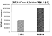
- Fig. 7 is a graph showing the fluorescence intensity on a living tissue when irradiating excitation light having a wavelength of 340 nm and observing fluorescence at a wavelength of 480 nm (in the case of a wavelength suitable for visualizing a heat invasive region).
- FIG. 6 is a graph showing the fluorescence intensity on a living tissue when irradiating excitation light having a wavelength of 380 nm and performing fluorescence observation at a wavelength of 530 nm (in the case of a wavelength suitable for visualizing a heat invasive region).
- FIG. 6 is a graph showing the fluorescence intensity on a living tissue when irradiating excitation light having a wavelength of 380 nm and performing fluorescence observation at a wavelength of 530 nm (in the case of a wavelength suitable for visualizing a heat invasive region).
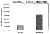
- FIG. 6 is a graph showing the fluorescence intensity on a living tissue when irradiating excitation light having a wavelength of 440 nm and performing fluorescence observation at a wavelength of 550 nm (in the case of a wavelength suitable for visualizing a heat invasive region).
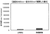
- FIG. 4 is a graph showing the fluorescence intensity on a living tissue when irradiating excitation light having a wavelength of 490 nm and observing fluorescence at a wavelength of 650 nm (in a case where the wavelength is not suitable for visualizing a heat invasion region)
- the thermal invasion observation apparatus performs a normal white light observation (WLI) and a special white light observation (WLI) on a region where a subject such as a living tissue is subjected to a thermal invasion such as cauterization using an energy device or the like.
- Light observation fluorescence observation
- Fluorescence observation is performed to acquire normal white light image data and fluorescence image data including fluorescence intensity information, and a predetermined form is obtained based on the acquired white light image data and fluorescence image data.
- Display image data is generated, and an image represented by the display image data is displayed in various display forms using a display unit (monitor).
- the thermal invasion observation apparatus of the present invention can clearly visualize the thermal invasion region by cauterization.
- a medical endoscope system mainly used in the medical field will be exemplified as an example of the thermal invasive observation device.
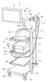
- FIG. 1 is an external perspective view showing an entire configuration of an endoscope system which is a heat invasive observation device according to an embodiment of the present invention.
- FIG. 2 is a block diagram showing a schematic configuration of the endoscope system of FIG.
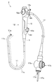
- FIG. 3 is an external perspective view showing an endoscope included in the endoscope system of FIG.
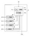
- FIG. 4 is a main part block configuration diagram illustrating a detailed configuration of a control unit of the light source device of the endoscope system in FIG. 1.
- an endoscope system 1 including a heat invasive observation device includes an endoscope 2, a light source device 3, a video processor 4, a monitor 5, It has a medical trolley 6 (not shown in FIG. 2) for holding them.
- the endoscope 2 mainly includes an elongated insertion section 11, an operation section 12, a universal cable 17, an endoscope connector 17b, and the like. I have.
- the insertion portion 11 is a tubular member formed into an elongated tube shape and inserted into the subject.
- the insertion portion 11 is formed by sequentially connecting a distal end portion 11a, a curved portion 11b, and a flexible tube portion 11c from the distal end side, and has flexibility as a whole.
- the distal end portion 11a includes an image pickup device 13 having an image sensor such as a CCD therein, an objective optical system 14 for forming an optical image of a subject on the image pickup device 13, and an insertion portion.
- One end of a light guide 15, which is an optical fiber inserted into the section 11, and an illumination optical system 16 as an irradiation section for irradiating illumination light guided by the light guide 15 toward an observation target (subject) Etc. are arranged.
- the bending portion 11b receives a turning operation of a bending operation lever 12a that is a bending operation member for performing a bending operation among a plurality of operation members (described later) provided in the operation portion 12, and moves up and down (UP and DOWN).
- This is a mechanism unit configured to be able to bend actively in two directions.
- the form of the bending portion in the endoscope to which the present invention can be applied is not limited to the above-described example (a type capable of bending in two directions), and includes a horizontal direction in addition to the vertical direction. And the like that can be bent in four directions including the vertical direction and the left and right directions (UP and DOWN and RIGHT and LEFT) in different directions. May be.
- the flexible tube portion 11c is a tubular member formed to have flexibility so as to be passively flexible. Inside the flexible tube portion 11c, in addition to a treatment tool insertion channel (not shown), the flexible tube portion extends from the image pickup device 13 built in the distal end portion 11a, passes through the inside of the operation portion 12, and enters the inside of the universal cable 17.
- a light guide 15 that guides various kinds of electric signal lines 13a extending therefrom and light emitted from a light source device 3 (described later) as an external device to an illumination optical system 16 provided on the distal end surface of the distal end portion 11a. Etc. are inserted.
- the operation unit 12 is a constituent unit that is provided continuously with the base end of the insertion unit 11 and includes a plurality of operation members and the like.
- the operation unit 12 includes a fold prevention unit 9, a grip unit 10, a plurality of operation members (12a, 12b, etc.), a treatment tool insertion unit 12d, a suction valve 12c, and the like.
- the buckling prevention portion 9 is provided at a connection portion between the distal end portion of the operation portion 12 and the base end portion of the flexible tube portion 8, and covers the base end portion of the flexible tube portion 8, whereby the endoscope 2 of the endoscope 2 is covered. It is a protective member for preventing the flexible tube portion 8 from being unnecessarily sharply broken during use.
- the grip 10 is a housing that stores various components therein.
- the grip 10 is connected to the buckling stopper 9.
- the grip 10 is a part that is held by the user (user) when the endoscope 2 is used.
- the treatment tool insertion section 12d has a treatment tool insertion port (not shown) for inserting various treatment tools (not shown), and has a treatment tool insertion passage communicating with a treatment tool insertion channel inside the operation section 12. It is a component.
- the treatment instrument insertion portion 12d is provided with a forceps stopper 12e which is a lid member for opening and closing the treatment instrument insertion opening and which is detachably attached to the treatment instrument insertion portion 12d.
- the operation unit 12 is provided with a bending operation lever 12a, various switches 12b, a suction valve 12c, and the like.
- the bending operation lever 12a is an operation member for performing the bending operation of the bending portion 11b.
- the various switches 12b include, for example, an operation member for performing an air / water supply operation and a suction operation, and an operation member for performing an operation corresponding to each of the imaging unit and the illumination unit.
- the suction valve 12c is a connecting portion for connecting a suction pipe line to a suction device (not shown).
- a universal cable 17 extends from the base end side of the operation unit 12.
- the universal cable 17 is a hollow tubular member having flexibility and extending from the operation unit 12. As shown in FIG. 2, the universal cable 17 is a composite cable into which the light guide 15, the electric signal line 13a extending from the image sensor 13, and the like are inserted.
- a connector 17b serving as a connection terminal with another device is provided at the extending end of the universal cable 17.
- the connector 17b has a light source connector 17a detachably connected to the light source device 3 at the distal end side, and an air / water supply tube (not shown) from an air / water supply device (not shown) which is an external device. Are provided (see FIGS. 1 to 3).
- the connector 17b is connected to an electric connector 17c (see FIGS. 2 and 3) to which a scope cable 18 (see FIGS. 1 and 2; not shown in FIG. 3) that is electrically connected to the electric signal line 13a is connected. Is provided.
- a signal connector 18a (see FIG. 2) which is detachably connected to the video processor 4 is provided at an extending end of the scope cable 18.
- the light source device 3 is a light source unit having a function of separately generating excitation light and white light as illumination light for irradiating an observation target (subject).
- the light source device 3 includes a control unit 21, a front panel 22, a lamp 23 as a light source, a first rotary filter 24, a diaphragm device 25, a second rotary filter 26, It has a lens 27 and the like.
- the control unit 21 controls the entire light source device 3 and controls the lamp 23 and the aperture device 25 based on a signal regarding brightness from the video processor 4.
- the control unit 21 includes a central processing unit (CPU), a ROM, a RAM, and the like. The detailed configuration of the control unit 21 will be described later.
- an observation mode changeover switch 22a for switching various observation modes (white light (normal light) observation mode, fluorescence (special light) observation mode, marking confirmation mode, etc.), and other various operation switches are provided. (Not shown).
- An operation signal from the front panel 22 is input to the control unit 21.
- the observation mode changeover switch 22a is a changeover switch for instructing switching between an illumination mode corresponding to the normal light observation mode and an illumination mode corresponding to the special light observation mode.
- the light source device 3 is configured to generate at least white light for normal light observation and excitation light that is a specific wavelength band light for special light observation.
- the lamp 23 is a light source for supplying illumination light to the subject, and for example, a xenon lamp or the like is applied. On / off control of the lamp 23 is performed according to a drive signal from the control unit 21.
- the first rotation filter 24 is a filter for selectively emitting either the wavelength band light for normal light observation or the wavelength band light for special light observation.
- the first rotation filter 24 is rotated around the rotation axis of the first rotation filter 24 based on a control signal from the control unit 21 to switch a filter corresponding to the mode designated by the observation mode changeover switch 22a to a lamp. It operates so as to be arranged on the optical path of the outgoing light of 23.
- the first rotary filter 24 is provided so as to be freely inserted into and removed from the optical path of the light emitted from the lamp 23, and when inserted in the optical path, a part of the light in the normal light observation mode in the special light observation mode.
- This is an optical filter that transmits band light.
- the light source is constituted by the lamp 23 and the optical filter of the first rotating filter 24. That is, in the special light observation mode, the light source device 3 causes the optical filter to be inserted into the optical path, and supplies the light transmitted through the optical filter to the light guide 15 as illumination light.
- the aperture device 25 is a light amount adjusting device that adjusts the emitted light amount of the illumination light supplied to the light guide 15.
- the diaphragm device 25 is driven in a direction to close or open the diaphragm based on a diaphragm drive signal from the control unit 21, so that the amount of light emitted from the lamp 23 is adjusted.
- the second rotating filter 26 is a filter unit configured to include, for example, an R (red) filter, a G (green) filter, and a B (blue) filter in order to emit light sequentially in a plane.
- the second rotation filter 26 rotates at a predetermined rotation speed around the rotation axis of the second rotation filter 26 based on the control signal from the control unit 21, and sequentially passes the three RGB filters on the optical path of the light emitted from the lamp 23. To be continuously arranged.
- the condensing lens 27 is an optical element for condensing the illumination light having passed through the two rotary filters (24, 26) on the base end face of the light guide 15.
- the control unit 21 of the light source device 3 selects the first rotation filter 24 so as to select a filter according to the observation mode changeover switch 22a, and controls the aperture device 25 based on a signal regarding brightness from the video processor 4. I do.
- An operation signal from the front panel 22 of the light source device 3 is input to the control unit 31, and the control unit 31 executes a process corresponding to the function of the switch operated on the front panel 22.
- control unit 21 includes various circuits mounted on a circuit board.
- the control unit 21 includes various chips and circuits mounted on the substrate.
- the control unit 21 includes an FPGA (Field Programmable Gate Array) 41, a lamp drive unit 42, filter drive units 43 and 44, an aperture drive unit 45, and the like.
- FPGA Field Programmable Gate Array
- the FPGA 41 has a CPU 41a, a storage unit 41b including a ROM and a RAM, and an aperture control unit 41c.
- the CPU 41a includes an illumination mode switching control unit that switches between an illumination mode corresponding to the normal light observation mode and an illumination mode corresponding to the special light observation mode based on a signal from the observation mode changeover switch 22a. .
- the aperture control unit 41c is a control unit that outputs an aperture drive control signal according to a brightness target signal from the video processor 4. That is, the aperture control unit 41c illuminates the aperture device 25, which is a light amount adjustment unit, based on a brightness target signal that is a light amount control signal generated based on the brightness of an image obtained by imaging the subject. The adjustment of the amount of emitted light is performed.
- the brightness target signal indicates a brightness target value
- the aperture control unit 41c operates the aperture device 25 so that the target value (abbreviated as brightness target value) indicated by the brightness target signal becomes a predetermined reference value. Control.
- the aperture control unit 41c generates an aperture drive control signal of an instruction to close or open the aperture device 25 according to whether the input brightness target value is larger or smaller than a predetermined reference value. And outputs it to the aperture driving unit 45.
- the lamp driving unit 42 outputs a lamp driving signal for turning on the lamp 23 as a light source based on a lamp driving control signal from the FPGA 41.
- the filter drive unit 43 outputs a motor drive signal for driving a motor (not shown) for rotating the first rotary filter 24 based on a filter drive control signal for controlling the first rotary filter 24 from the FPGA 41. .
- the filter drive unit 44 outputs a motor drive signal for driving a motor (not shown) for rotating the second rotary filter 26 based on a filter drive control signal for controlling the second rotary filter 26 from the FPGA 41.
- the aperture drive unit 45 outputs an aperture drive signal for driving the aperture device 25 based on an aperture drive control signal from the FPGA 41 for controlling the aperture device 25.
- a current aperture value based on a detection signal from a position detector such as a potentiometer provided in the aperture device 25 is fed back and input to the aperture drive unit 45, and the feedback signal is sent to the aperture control unit 41c. Has been entered.
- the aperture drive unit 45 that drives the aperture device 25 in response to the aperture drive control signal input from the aperture control unit 41c forms a light amount adjustment unit together with the aperture device 25, the aperture control unit 41c, and the like.
- the light source device 3 as a light source unit in the endoscope system 1 of the present embodiment is a xenon lamp or the like that emits white light, which is normal light, as a light source for supplying illumination light to the subject. Is applied, and the white light is transmitted through the first rotating filter 24, so that the wavelength band light for normal light observation and the wavelength band light for special light observation are selectively emitted.
- the configuration of the light source unit in the endoscope system 1 of the present invention is not limited to the configuration described above, and may be other forms.
- As another configuration of the light source unit for example, a plurality of types of light emitting diodes (light emitting diodes) that can emit light of a specific wavelength are prepared, and the light emission of the plurality of light emitting diodes is set according to the observation mode. It is conceivable to adopt a configuration in which switching is performed as needed.
- the video processor 4 controls the entire endoscope system 1, which is the thermal invasive observation apparatus of the present embodiment, and also converts the image data of the subject as the observation target acquired by the endoscope 2. It is a processing device for performing various data processing related to various types of information.
- the video processor 4 mainly includes a control unit 31, a light control unit 32, an imaging drive unit 33, an image processing unit 34, a storage unit 35, a notification unit 36, and the like. Have been.
- the control unit 31 is a processing unit for controlling the entire video processor 4, and controls the light control unit 32, the imaging drive unit 33, the image processing unit 34, and the like according to the observation mode specified by the user (user). It is configured to include a controlling CPU (Central Processing Unit) and the like.
- CPU Central Processing Unit
- the dimmer 32 generates a brightness target signal from brightness information (brightness information) of an image signal generated by the image processor 34 and displayed on the monitor 5, and supplies the brightness target signal to the controller 21 of the light source device 3.
- the brightness target signal is, for example, a signal indicating a value calculated and determined according to a comparison result between the brightness of an image signal displayed on the monitor 5 and a reference brightness.
- the dimming unit 32 includes the imaging device 13, the image processing unit 34, and the like, around the distal end 11 a of the insertion unit 11 of the endoscope 2 (around the subject that is the observation target). ) Functions as an ambient light detection unit for detecting the amount of light.
- the imaging drive unit 33 is a circuit that outputs an imaging drive signal for driving the imaging device 13 based on an imaging drive control signal from the control unit 31.
- the image processing unit 34 has a function of receiving an image signal from the image sensor 13 under the control of the control unit 31 and executing various image signal processes on the image signal. Further, the image processing unit 34 has a function of generating display image data for displaying an image based on the processed image signal on the monitor 5 and outputting this to the monitor 5.
- the image processing unit 34 includes a fluorescent image generating unit 34a, a white light image generating unit 34b, an information generating unit 34c, a display image generating unit 34d, a heat invasion depth calculating unit 34e, and the like. I have.
- the fluorescence image generation unit 34a receives the excitation light from the light source device 3 and, based on an imaging signal acquired by imaging the fluorescence generated from the heat invasive region of the subject by the imaging device 13 of the endoscope 2. , A circuit unit or program software for generating corresponding fluorescent image data.
- the white light image generation unit 34b receives reflected light from the subject out of the white light emitted from the light source device 3 (light source unit) to the subject, and captures and acquires the image with the imaging element 13 of the endoscope 2.
- the information generation unit 34c calculates fluorescence intensity information of a predetermined area (heat invasion area) in the fluorescence image represented by the fluorescence image data based on the fluorescence image data generated by the fluorescence image generation unit 34a. It is a circuit unit or program software.
- the information generation unit 34c is a circuit unit or a program software that further generates a fluorescence intensity information icon from the fluorescence intensity information calculated based on the fluorescence image data generated by the fluorescence image generation unit 34a.
- the information generation unit 34c includes: fluorescence intensity information calculated from the fluorescence image data generated by the fluorescence image generation unit 34a; and predetermined relation information (details described later) stored in the storage unit 35 described later.
- the fluorescence intensity information includes heat invasion range information indicating a heat invasion area where the fluorescence intensity in the fluorescence image is equal to or higher than a predetermined intensity, and distribution of the fluorescence intensity on the surface of the subject within the heat invasion area.
- This is information including thermal invasion degree distribution information to be expressed, information on the depth of heat invasion from the surface of the subject within the range of the thermal invasion area, and the like.
- This fluorescence intensity information is a plurality of pieces of information included in the fluorescence image data.
- the fluorescence intensity information icon is represented in a form in which the information is symbolized by a figure or a character in a form that is clearly and easily visible for each type by visual observation. is there.
- the heat invasion depth information is information indicating the degree of depth heat invasion in the heat invasion area.
- the heat invasion depth is calculated based on data of a predetermined area (heat invasion area) of the fluorescence image data and predetermined relation information (relation information indicating a correlation between the fluorescence intensity of the fluorescence image and the heat invasion depth). Information.
- the display image generation unit 34d is a circuit unit or program software that generates display image data to be displayed on the monitor 5 (display unit) based on the white light image data and the fluorescence intensity information.
- the display image generating unit 34d is a circuit unit or a program software that generates display image data to be displayed in a form in which fluorescence intensity information is superimposed on an image represented by white light image data and displayed in an emphasized manner. .
- the display image generation unit 34d is a circuit unit or program software that generates display image data in a form in which a prepared fluorescence intensity information icon is superimposed on an image represented by white light image data. .
- the display image generation unit 34d is a circuit unit or program software that generates image data for superimposing and displaying heat invasion depth information on a display image output to the display unit.
- the heat invasion depth calculation unit 34e calculates the heat invasion depth in a predetermined area (heat invasion area) of the image area represented by the fluorescence image data by using the fluorescence image data and the relation information stored in the storage unit 35. Is a circuit unit or program software calculated based on the following.
- the storage unit 35 is a data storage in which various kinds of predetermined information data, software programs, and the like are stored in advance.
- the storage unit 35 stores, for example, information data related to relationship information indicating a correlation between the fluorescence intensity in the fluorescence image and the heat invasion depth in the living tissue that generates the fluorescence intensity.
- the notification unit 36 is a notification information generation unit that generates various (warning, notification, etc.) messages appropriately issued during use of the endoscope system 1 and notification information such as use guide information such as handling procedures and support information. It is.
- the notification information generated by the notification unit 36 is output to, for example, a notification device and transmitted to a user (user).
- a notification device for example, in addition to the monitor 5 (display unit) that visually outputs (displays) the notification information, a sound generation device such as a speaker that outputs the notification information as sound information is applied. You can also.
- the notification unit 36 generates corresponding notification information when the value of the invasion depth of the heat invasion area calculated by the heat invasion depth calculation unit 34e has reached a predetermined depth or more.
- the notification information is configured to be displayed in a predetermined area on the display screen of the monitor 5.
- the notification information is mainly generated in the notification unit 36.
- the information generation unit 34c or the heat invasion depth calculation unit 34e may be configured to generate the notification information based on the heat invasion depth calculated by the heat invasion depth calculation unit 34e. Can also.
- the monitor 5 includes an image based on various image data such as fluorescence image data and white light image data, various information related to the display image, and various setting information related to the endoscope system 1. It is a display device and a display unit that displays various information such as various information (patient chart information and the like) on the subject to be observed in a predetermined form that can be visually observed.
- the trolley 6 includes a trolley body 50 and an endoscope gantry device 51 attached to the trolley body 50.
- the trolley main body 50 has a frame 55 having a substantially inverted U-shape in a front view.
- a plurality of shelves 56 are installed on the frame 55.
- the light source device 3 and the video processor 4 are placed in an overlapping manner.
- various other devices constituting the endoscope system 1 are placed on each shelf 56 as necessary.
- a caster 57 for moving the trolley 6 on the floor is provided on the rear surface of the shelf 56 located at the lowest stage.
- a display unit mounting arm 58 is fixed to the top of the frame 55, and the display unit 5 is mounted on the free end side of the display unit mounting arm 58.
- the endoscope gantry device 51 includes a column 60, a column receiving portion 61 for supporting a base end side (lower end side) of the column 60, and, for example, two columns provided on the distal end side (upper end side) of the column. It has a hanger 62 and the like.
- the strut 60 is formed of a rod-shaped member formed such that a predetermined section on the distal end side extends in the horizontal direction by being bent halfway.
- a hanger support 60a is formed in a section of the support 60 extending in the horizontal direction.
- the support receiving portion 61 is fixed to one side of the frame 55 (for example, the right side of the frame 55 in the illustrated example).
- the strut receiving portion 61 is formed in a pipe shape with an open upper end, and is formed so that the base end side of the strut 60 can be inserted therein.
- a knurled screw type column fixing portion 61a for fixing the base end side of the column 60 inserted into the column receiving portion 61 at an arbitrary height is provided at the upper end portion of the column receiving portion 61. Is provided.
- the configuration of which the description is omitted is substantially the same as the configuration of an endoscope system which is widely used in the related art.
- marking for specifying the position of a lesion to be operated is performed.
- ESD Endoscopic Submucosal Dissection
- (1: Confirmation) Confirm the lesion (living tissue) under endoscopic observation
- (2: Marking) Using a treatment tool such as an energy device such as an electric scalpel inserted through the treatment tool insertion channel of the endoscope, a marking is made to cauterize by applying heat energy to the periphery of the lesion.
- the amino acids and reducing sugars in the living tissue are heated to cause a Maillard reaction, thereby generating AGEs.
- the AGEs include a substance having a fluorescent property.
- the fluorescence emitted from the AGEs in the heat invasion area is observed.
- these AGEs are generated in the heat-invasive area by heating, but are not limited to this, and are known to be present in the human body. Has been pointed out.
- AGEs are said to be included in aging substances and cancer tissues. It is said that AGEs affect aging of living tissues, wrinkles, spots, cancer, osteoporosis, Alzheimer's disease, cataract, arteriosclerosis, diabetes and the like. Therefore, the technology for visually detecting AGEs is useful in the medical field.
- the heat invasion region can be visualized by observing (imaging) fluorescence having a wavelength of 400 to 590 nm. Also, when at least the excitation light having a wavelength of 400 to 480 nm is irradiated, the heat invasion region can be visualized by observing (imaging) the fluorescence having a wavelength of 510 to 600 nm.
- FIG. 10 is a graph of the fluorescence intensity on a living tissue when irradiating excitation light having a wavelength of 340 nm and observing fluorescence at a wavelength of 480 nm.
- FIG. 11 is a graph showing the fluorescence intensity on the living tissue when irradiating excitation light having a wavelength of 380 nm and observing fluorescence at a wavelength of 530 nm.
- FIG. 12 is a graph of the fluorescence intensity on the living tissue when irradiating excitation light having a wavelength of 440 nm and observing fluorescence at a wavelength of 550 nm.
- FIGS. 10 to 12 shows a case where excitation light (300 to 400 nm) and fluorescence (400 to 590 nm) having wavelengths suitable for visualizing the heat invasion region are selected.
- excitation light 300 to 400 nm
- fluorescence 400 to 590 nm
- the difference between the fluorescence intensities increases, so that the image can be clearly displayed.
- FIG. 13 is a graph of the fluorescence intensity on the living tissue when irradiating excitation light having a wavelength of 490 nm and observing fluorescence at a wavelength of 650 nm.
- FIG. 14 is a graph of the fluorescence intensity on the living tissue when irradiating excitation light having a wavelength of 410 nm and observing fluorescence at a wavelength of 430 nm.
- the region subjected to the heat invasion receives the excitation light from the light source device 3 to generate fluorescence.
- the image signal acquired by the image sensor 13 is subjected to predetermined image processing by the fluorescent image generating unit 34a of the image processing unit 34, and the fluorescent image data is converted. Generated.
- the fluorescence image data thus generated is subjected to predetermined data processing in the image processing unit 34, is converted into image data in a display form, and is output to the monitor 5. Then, the monitor 5 displays a fluorescent image corresponding to the fluorescent image data and various information related thereto.
- the fluorescent image displayed on the monitor 5 is in a state in which the region (marking region) subjected to the heat invasion is visualized in a clear state with respect to the peripheral region.
- the display at this time mainly uses the heat invasion range information of the fluorescence intensity information included in the fluorescence image data.
- steps (1) to (4) are performed in the same manner as the above-mentioned ESD procedure. I do.
- the marking area due to the heat invasion to the inside (mucosa side) performed in the marking step (2) above is also confirmed from outside by fluorescence observation under a laparoscope. can do.
- the full-layer separation step (6) by performing fluorescence observation under a laparoscopic scope, it is possible to determine whether the energy device is on the incision line around the ESD without using an endoscope without using an endoscope. (Serosa side). In other words, in the full-layer separation step (6), the procedure can be performed only with a laparoscope. Therefore, confirmation under an endoscope can be unnecessary.
- NEWS Non-exposed / Endoscopic / Wall-inversion / Surgery
- the marking area due to the heat invasion to the inside (mucosa side) performed in the marking step (2) above is also confirmed from outside by fluorescence observation under a laparoscope. can do.
- the second marking step (3) can be omitted.
- the endoscope system 1 of the present embodiment by observing the marking area due to the heat invasion with the fluorescent light, it is possible to easily confirm the marking area clearly even from outside the target subject (living tissue). Can be. Therefore, a part of the internal and external cooperative work performed in the conventional procedure, a special marking method, and the like can be omitted, which can contribute to simplification of the procedure.
- FIG. 5 is a diagram showing a first modification of the display of the marking area due to heat invasion in the endoscope system according to one embodiment of the present invention.
- frames indicated by reference numerals 5A, 5B, and 5C are display frames of the monitor 5.
- a state is shown in which a lesion 100 to be observed and a marking area (heat invasion area) 101 provided around the lesion 100 are displayed.
- the display frame 5A conceptually shows the display state of the target lesion 100 and the surrounding marking area (heat invasion area) 101 when normal white light observation (WLI) is performed.
- the setting at this time is referred to as a white light observation mode (or a normal light observation mode).
- the lesion 100, the surrounding marking area 101, and the surrounding normal tissue are not clearly displayed. The situation where 101 is easily overlooked is shown.
- the display frame 5B conceptually shows the display state of the target lesion 100 and the surrounding marking area (heat invasion area) 101 when performing the fluorescence observation.
- the setting at this time is referred to as a fluorescence observation mode.
- the lesion 100 and the surrounding marking area 101 are clearly displayed on the surrounding normal tissue, and the lesion 100 and the marking area 101 are displayed. A situation that is easy to identify is illustrated.
- the present modification has a marking confirmation mode in which the marking area 101 around the lesion 100 is displayed in a more easily identifiable form so that confirmation can be easily performed.
- the display frame 5C in FIG. 5 illustrates a display example at this time.
- display image data to be displayed on the monitor 5 based on white light image data and fluorescence image data obtained by simultaneously performing white light observation (WLI) and fluorescence observation. Is generated.
- the image data of the area corresponding to the marking area (heat invasion area) 101 around the target lesion 100 is extracted from the fluorescent image data, and the extracted data is subjected to a predetermined enhancement process (for example, contour enhancement or Extraction-enhanced data that has been subjected to image processing such as coloring processing in the corresponding area is generated. Then, a process of superimposing and displaying the extracted emphasized data on the corresponding area in the white light image data is performed.
- An image displayed by outputting the display image data thus obtained to the monitor 5 is as shown in a display frame 5C in FIG.
- the display frame 5C conceptually represents the display state of the target lesion 100 and the surrounding marking region (heat invasion region) 101 when the region including the target lesion 100 is observed in the marking confirmation mode. Is shown.
- the marking area 101 around the lesion 100 is more clearly displayed on the lesion 100 and surrounding normal tissue, and the marking area 101 is A situation that is easier to identify is shown.
- the marking confirmation mode for performing the image processing for displaying the marking area 101 in a more emphasized manner, the position of the lesion 100 surrounded by the marking area 101 can be surely grasped. In addition, it is possible to prevent the lesion 100 from being overlooked.
- the white light observation mode, the fluorescence observation mode, and the marking confirmation mode can be arbitrarily switched by the user (user) appropriately operating the observation mode switch 22a of the front panel 22 when desired. It has become.
- observation mode changeover switch 22a is provided on the front panel 22 of the light source device 3, but the arrangement of the observation mode changeover switch 22a is not limited to this.
- observation mode changeover switch 22a may be provided on the surface of the operation unit 12 of the endoscope 2.
- the user can conveniently switch the observation mode at a desired timing while operating the endoscope 2, which is convenient.
- the observation mode changeover switch 22a may be provided on each of the front panel 22 and the operation unit 12 of the light source device 3.
- the extraction emphasis data generated by extracting the image data of the area corresponding to the marking area (heat invasion area) 101 is used.
- the example in which the display is superimposed on the corresponding area of the white light image data has been described, another display form may be adopted as follows.
- a fluorescence intensity information icon is generated by iconifying the generated extracted and emphasized data, and this icon is superimposed on the corresponding area of the white light image data.
- the data can be reduced by the iconization process. Therefore, it is possible to contribute to the reduction of the capacity of the display image data, and to increase the display speed.
- the information used in this case mainly uses the heat invasion range information of the fluorescence intensity information included in the fluorescence image data.
- Fluorescent image data acquired by the endoscope system 1 which is the thermal invasive observation device of the present embodiment contains much more information.
- a display example in the case of using other information of the fluorescence intensity information included in the fluorescence image data for example, heat invasion degree distribution information, heat invasion depth information, and the like will be described.
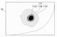
- FIG. 6 shows a second example of a display example when a subject is cauterized by heat invasion using the endoscope system 1 of the present embodiment and the subject including the cauterized region is observed in a fluorescence observation mode.
- FIG. 7 is a display example in which the depth of heat invasion estimated from the result calculated using the heat invasion depth information among the fluorescence intensity information included in the fluorescence image data of FIG. 6 is displayed.
- the fluorescence image data obtained by performing the fluorescence observation on the cauterized region subjected to the cauterization by the heat invasion using the endoscope system 1 of the present embodiment includes the heat invasion degree distribution information and the heat invasion depth information. And are included.
- a display mode (see display frame 5D in FIG. 6) in which the distribution of the fluorescence intensity within the range of the heat invasion region is displayed using the heat invasion degree distribution information is realized. I have.
- the distribution of the fluorescence intensity is classified into a plurality of regions (reference numerals 110A, 110B, and 110C in FIG. 6) within the range of the cauterization region (heat invasion region) 110 due to the heat invasion, and the form is different.
- regions reference numerals 110A, 110B, and 110C in FIG. 6
- the form is different.
- This makes it possible to display the distribution of the fluorescence intensity on the surface of the subject within the range of the heat invasion region in a visible state.
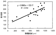
- the relationship information indicating the correlation between the fluorescence intensity and the heat invasion depth is stored in the storage unit. 35.
- FIG. 15 is a diagram showing a correlation between the fluorescence intensity and the heat invasion depth.
- the vertical axis indicates the fluorescence intensity.
- the fluorescence intensity indicates the luminance value (0 to 255) of the pixel of the acquired fluorescence image (no unit).
- the heat invasion depth calculation unit 34e calculates the relation information of the storage unit 35 and the heat invasion depth information of the heat invasion area included in the fluorescence image data obtained by the fluorescence observation.
- the heat invasion depth is calculated based on the above.
- the heat invasion depth result obtained in this manner according to the display form as shown in FIG. 7, that is, the distribution of the fluorescence intensity (110A, 110B, 110C) in the ablation region (heat invasion region) 110 due to heat invasion.
- the estimated depth is displayed (see display frame 5E in FIG. 7).
- FIG. 7 The display example shown in FIG. 7 indicates that the invasion depth is different depending on the fluorescence intensity distribution shown in FIG.
- reference numerals 110A, 110B, and 110C correspond to reference numerals 110A, 110B, and 110C, respectively, which indicate the distribution areas shown in FIG.
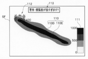
- FIGS. 8 and 9 are tables showing a case where the subject is cauterized by heat invasion using the endoscope system 1 of the present embodiment, and the subject including the cauterized region is observed in the fluorescence observation mode. 13 shows a third modification of the illustrated example.
- the depth of the heat invasion estimated from the result calculated using the heat invasion degree distribution information and the heat invasion depth information among the fluorescence intensity information included in the fluorescence image data is displayed. This is a display example.
- the target region is a cauterized region formed by heat invasion and formed in a substantially elongated shape on the surface of the subject.
- reference numerals 110D and 110E in FIG. 8 represent the thermal invasion degree distribution.
- the number displayed in the vicinity of the cautery region (heat invasion region) 110 indicates the specific information of the heat invasion depth calculated according to the distribution information. It is a display.
- a graph 111 representing the standard of the grayscale information representing the distribution of the fluorescence intensity is a predetermined area in the display area in the display frame 5F (in the example shown in FIG. 8, an area near the lower right edge toward the display frame 5F). It is configured to be displayed according to.
- the cautery region 110 formed by heat invasion and formed in a substantially circular shape on the surface of the subject is the target region.
- reference numerals 110F, 110G, and 110H in FIG. 9 represent the thermal invasion degree distribution.
- the display frame 5G of the monitor 5 in the vicinity of the cautery area (heat invasion area) 110, specific information of the heat invasion depth calculated according to the distribution information is displayed by a numeral.
- the points are the same as the display example of FIG.
- the graph 111 is the same as in FIG.
- the ablation range (distribution) and the invasion range (invasion depth) can be clearly displayed.
- an area to be cauterized (an area including a target lesion) is displayed on the monitor 5. This is performed while viewing the endoscope image.
- the white light observation and the fluorescence observation are simultaneously performed, the white light image data and the fluorescence image data are simultaneously acquired, and the fluorescence intensity information included in the fluorescence image data is obtained.
- predetermined image signal processing using (in particular, thermal invasion degree distribution information and thermal invasion depth information)
- a display image in a form in which the ablation range (distribution) and the invasion range (invasion depth) are clarified is obtained. Can be observed in real time.
- the surgeon such as a doctor can perform the procedure while constantly checking the degree of invasion of the target area.
- the energy device is unintentionally thermally invaded into a normal region other than the target region. Such accidents can be suppressed.
- the heat invasion depth calculation unit 34e calculates the heat invasion depth as described above.
- a notification unit 36 that notifies the user of the notification information is provided.
- the notification unit 36 outputs the generated notification information to the monitor 5 as described above, and provides a visual notification on the display screen of the monitor 5 (display unit). Display as information. Examples of the display include, for example, an indicator such as reference numeral 112 shown in FIG. 8, a warning display (display of character information, pictograms, and the like) indicated by reference numeral 113 in FIG. A warning icon or the like stored in the unit 35 or the like may be appropriately read and displayed.
- the display is designed to more easily draw the operator's attention by displaying the character color in red or the like, or performing blinking display. Can be considered.
- a sound generation device such as a speaker that outputs the notification information as sound information may be applied.
- white light observation and fluorescence observation can be performed simultaneously to obtain white light image data and fluorescence image data simultaneously.
- differential data is obtained by performing predetermined image processing based on the fluorescence image data before and after the treatment. It can be said that this difference data is data that accurately represents the difference in the intensity of the autofluorescence before and after the heat invasive treatment by the energy device in a form from which noise has been removed.
- the fluorescence image data of the “burn site” and “ Means for obtaining difference data from the fluorescence image data of the “part to be burned and not to be burned (not burnt)” may be considered.
- the monitor 5 can clearly and accurately display only the autofluorescent region generated by heat invasion. Will be able to
- the range (distribution and depth) of the cautery region of the living tissue caused by the thermal invasion using the energy device is determined by the biological tissue. It can be easily visualized by detecting the autofluorescence of the tissue.
- various image signal processing is performed by focusing on the fact that there is a correlation between the depth of heat invasion and the intensity of fluorescence, so that operators (users and users) such as doctors can perform heat invasion in real time.
- the range of the ablation region can be confirmed. Therefore, by using the endoscope system 1 of the present embodiment, it is possible to easily perform a reliable and highly accurate minimally invasive operation.
- the range in the depth direction (surface distribution) in addition to the range (surface distribution) on the surface of the living tissue of the subject, the range in the depth direction (surface distribution) (Depth distribution).
- the present invention is not limited to the above-described embodiment, and it is needless to say that various modifications and applications can be made without departing from the gist of the invention.
- the above embodiments include inventions at various stages, and various inventions can be extracted by appropriately combining a plurality of disclosed constituent elements. For example, even if some components are deleted from all the components shown in the one embodiment, if the problem to be solved by the invention can be solved and the effect of the invention can be obtained, this configuration is deleted. The configuration can be extracted as an invention. Further, components of different embodiments may be appropriately combined. The invention is not limited by the specific embodiments thereof except as limited by the appended claims.
Landscapes
- Health & Medical Sciences (AREA)
- Life Sciences & Earth Sciences (AREA)
- Surgery (AREA)
- Engineering & Computer Science (AREA)
- Medical Informatics (AREA)
- General Health & Medical Sciences (AREA)
- Nuclear Medicine, Radiotherapy & Molecular Imaging (AREA)
- Veterinary Medicine (AREA)
- Physics & Mathematics (AREA)
- Public Health (AREA)
- Biomedical Technology (AREA)
- Heart & Thoracic Surgery (AREA)
- Animal Behavior & Ethology (AREA)
- Molecular Biology (AREA)
- Biophysics (AREA)
- Optics & Photonics (AREA)
- Pathology (AREA)
- Radiology & Medical Imaging (AREA)
- Signal Processing (AREA)
- Neurology (AREA)
- Plasma & Fusion (AREA)
- Neurosurgery (AREA)
- Otolaryngology (AREA)
- Endoscopes (AREA)
- Surgical Instruments (AREA)
Abstract
本発明は、エネルギーデバイス等を用いた生体組織等の被検体への焼灼状態を可視化する熱侵襲観察装置を提供することを目的とし、そのために、被検体に照射するための励起光を発生させる光源部3と、励起光を受けて被検体の熱侵襲領域から発生した蛍光を撮像して取得された撮像信号に基づいて蛍光画像データを生成する蛍光画像生成部34aと、蛍光画像データを含む画像データに基づく画像及び情報を表示する表示部5とを具備する。
Description
この発明は、エネルギーデバイス等を用いた生体組織等の被検体への焼灼状態を可視化する熱侵襲観察装置,内視鏡システム,熱侵襲観察システム,熱侵襲観察方法に関するものである。
従来、主に医療分野において用いられる医療用内視鏡には、光の波長を制御して観察対象物を強調表示する特殊光観察機能を搭載した内視鏡ビデオスコープシステムが一般に実用化されている。
例えば、狭帯域光観察(NBI:Narrow Band Imaging(登録商標))機能は、血液中のヘモグロビンに吸収されやすい狭帯域化された2つの波長(390~445nm/530~550nm)の光を生体組織等の被検体(以下、単に被検体という)に対して照射することによって、粘膜表層の毛細血管や粘膜微細模様の強調表示を実現している。
また、赤外光観察(IRI:Infra Red Imaging)機能は、赤外光が吸収されやすい赤外指標薬剤を静脈注射した上で、2つの赤外光(790~820nm/905~970nm)を被検体に対して照射することによって、通常光観察では視認が難しい粘膜深部の血管や血流情報の強調表示を実現している。
そして、蛍光観察(AFI:Auto Fluorescence Imaging)機能は、生体組織からの自家蛍光を観察するための励起光(390~470nm)と血液中のヘモグロビンに吸収される波長(540~560nm)の光を被検体に対して照射することによって、腫瘍性病変と正常粘膜とを異なる色調で強調表示することを実現している。つまり、蛍光観察(AFI)機能は、生体粘膜からの自家蛍光を観察することにより、腫瘍性病変と正常組織を異なる色調で強調表示することができる技術である。
近年においては、これらの特殊光観察機能を用いることにより、癌などの微細病変の早期発見や術前の病変範囲の精密診断等のための画像データを容易に取得して、医師による精密診断をサポートすることができるようになっている。
しかしながら、これら従来の特殊光観察機能は、主に病変部の表面の観察を行うものであるので、被検体の表面に生じた病変部の範囲を把握することは目視によっても容易にできるが、その病変部の深さ情報等については、目視だけでは容易に判断することが困難である。
そこで、例えば、従来の特殊光観察機能によって得られた画像データに基づいて、病変部や傷害部位の深さ情報を評価したり推定するための技術が、従来、種々提案されている。
例えば、日本国特許公表平10-505768号公報には、紫外光または青光による誘起蛍光分光法や、可視光及び赤外光の反射分光法とを用いて、皮膚の熱傷傷害の範囲と深さとを医師が迅速に評価することのできる熱傷傷害評価装置とその評価方法が開示されている。この熱傷傷害評価装置は、予め定められた複数種類の波長の励起光をそれぞれ出射する複数の光源と、これらの光源から出射されて被検体により反射された応答光量を測定するセンサと、マイクロプロセッサ等を具備し、熱傷部位の皮膚を光学的に評価するように構成されている。
また、日本国特許公開2012-130506号公報には、吸光成分濃度の推定の確からしさを高めた光計測システムとしての電子内視鏡システムと、その光計測方法が開示されている。この電子内視鏡システムは、被検体に励起光を照射して血管に注入された赤外指標薬剤(インドシアニングリーン:ICG(Indocyanine green))を励起させ、これを撮像して得られた撮像信号に基づいて、被検体の表面からの血管の深さを推定することができるというものである。
そして、日本国特許公開2008-229025号公報には、蛍光観察機能を用いて取得された蛍光画像データについて、精度よく補正することにより、病変部の正確な診断をおこなうことができるようにした蛍光観察装置が開示されている。
ところが、上記日本国特許公表平10-505768号公報,上記日本国特許公開2012-130506号公報,上記日本国特許公開2008-229025号公報等によって開示されている装置は、いずれもが特殊光観察機能を用いて取得された画像データに基づいて病変部に関する情報のうち目視によっては取得し得ない情報、例えば病変部の深さ情報等を評価し推定するというものである。したがって、これらの従来技術では、病変部に関する情報について高精度な情報を常に確実に取得することができるとは限らないという問題点がある。
一方、近年においては、内視鏡や腹腔鏡等を用いた低侵襲手術が広く行われるようになっている。例えば、腹腔鏡内視鏡合同胃局所切除術(LECS:Laparoscopy and Endoscopy Cooperative Surgery),非穿孔式内視鏡的胃壁内反切除術(NEWS:Non-exposed Endoscopic Wall-inversion Surgery),内視鏡的粘膜下層剥離術(ESD:Endoscopic Submucosal Dissection)等が広く行われている。
これらの低侵襲手術を行う際には、例えば、手術対象領域のマーキング等のために、電気メス等のエネルギーデバイスを用いて生体組織等の被検体に対する熱侵襲操作が実行される。また、実際の手術の際にも、同電気メス等のエネルギーデバイスを用いて患部生体組織の切除等が行われる。
このとき、当該エネルギーデバイスによって被検体の所望の部位に加えられる熱侵襲の度合いは、医師等の術者が目視や触覚,勘などに頼って確認を行っているのが実情である。
一般に、生体組織等の被検体に対して熱侵襲を加えた部位を通常光(白色光)で観察すると、その表面が白く変化していることがわかる。
ここで、熱侵襲を加えた対象の被検体が、例えば脂肪等の白色組織である場合には、熱侵襲を加えた部位と、熱侵襲を加えていない正常部位との間の見分けがつき難い。したがって、例えば手術等の作業途中で熱侵襲を加えた部位を、時間をおいた後に探す場合、容易に見つけられずに、見落としてしまうことがよくある。
したがって、医師等の術者が、例えば、手術等の作業中に熱侵襲を加えるべき度合い等をリアルタイムで目視のみによって確認することは非常に困難なことであり、非常に熟練を要する作業項目となっていた。
本発明は、上述した点に鑑みてなされたものであって、その目的とするところは、エネルギーデバイス等を用いた生体組織等の被検体への焼灼状態を可視化する熱侵襲観察装置,内視鏡システム,熱侵襲観察システム,熱侵襲観察方法を提供することである。
上記目的を達成するために、本発明の一態様の熱侵襲観察装置は、生体組織への熱侵襲を観察する熱侵襲観察装置であって、熱侵襲領域に含有される物質を励起させるための励起光が照射された生体組織における熱侵襲領域から発生した蛍光を撮像して生成される撮像信号を取得して、取得した前記撮像信号に基づいて蛍光画像データを生成する蛍光画像生成部と、を具備する。
本発明の一態様の内視鏡システムは、生体組織に含まれるAGEs(終末糖化産物)を観察する内視鏡システムであって、AGEsを励起させるための励起光を発生することが可能な光源部と、励起光が照射されたAGEsから発生した蛍光を取得して撮像信号を生成する撮像部と、撮像信号に基づいて前記蛍光画像データを生成する画像生成部と、を備える。
本発明の一態様の熱侵襲観察システムは、生体組織への熱侵襲を観察する熱侵襲観察システムであって、熱侵襲領域に含有される物質を励起させるための励起光を発生させる光源部と、励起光が照射された生体組織における熱侵襲領域から発生した蛍光を撮像して撮像信号を生成する撮像部と、前記撮像部が蛍光を撮像して生成した撮像信号に基づいて、蛍光画像データを生成する蛍光画像生成部と、を有する。
本発明の一態様の熱侵襲観察方法は、生体組織への熱侵襲を観察する熱侵襲観察方法であって、熱侵襲領域に含有される物質を励起させるための励起光を発生させ、励起光が照射された生体組織における熱侵襲領域から発生した蛍光を撮像して撮像信号を生成し、撮像部が蛍光を撮像して生成した撮像信号に基づいて、蛍光画像データを生成する。
本発明によれば、エネルギーデバイス等を用いた生体組織等の被検体への焼灼状態を可視化する熱侵襲観察装置,内視鏡システム,熱侵襲観察システム,熱侵襲観察方法を提供することができる。
以下、図示の実施の形態によって本発明を説明する。
以下の説明に用いる各図面は模式的に示すものであり、各構成要素を図面上で認識できる程度の大きさで示すために、各部材の寸法関係や縮尺等を構成要素毎に異ならせて示している場合がある。したがって、本発明は、各図面に記載された各構成要素の数量や各構成要素の形状や各構成要素の大きさの比率や各構成要素の相対的な位置関係等に関して、図示の形態のみに限定されるものではない。
本発明の熱侵襲観察装置は、エネルギーデバイス等を用いて生体組織等の被検体に対して焼灼等の熱侵襲を加えた領域に対し、通常の白色光観察(WLI;white light imaging)と特殊光観察(蛍光観察)とを行い、通常の白色光画像データと、蛍光強度情報を含む蛍光画像データとを取得し、取得された白色光画像データと蛍光画像データとに基づいて所定の形態の表示用画像データを生成し、表示用画像データによって表される画像を、表示部(モニタ)を用いて、様々な表示形態で表示する。これにより、本発明の熱侵襲観察装置は、焼灼による熱侵襲領域を明瞭に可視化することができるものである。
以下に説明する一実施形態においては、熱侵襲観察装置の一例として、主に医療分野において用いられる形態の医療用内視鏡システムを例示するものとする。
[一実施形態]
図1は、本発明の一実施形態の熱侵襲観察装置である内視鏡システムの全体構成を示す外観斜視図である。図2は、図1の内視鏡システムの概略構成を示すブロック構成図である。図3は、図1の内視鏡システムに含まれる内視鏡を示す外観斜視図である。図4は、図1の内視鏡システムの光源装置の制御部の詳細構成を示す要部ブロック構成図である。
図1は、本発明の一実施形態の熱侵襲観察装置である内視鏡システムの全体構成を示す外観斜視図である。図2は、図1の内視鏡システムの概略構成を示すブロック構成図である。図3は、図1の内視鏡システムに含まれる内視鏡を示す外観斜視図である。図4は、図1の内視鏡システムの光源装置の制御部の詳細構成を示す要部ブロック構成図である。
本発明の一実施形態の熱侵襲観察装置を含む内視鏡システム1は、図1,図2に示すように、内視鏡2と、光源装置3と、ビデオプロセッサ4と、モニタ5と、これらを保持するための医療用トロリー6(図2には不図示)等を有して構成されている。
まず、内視鏡2は、図1~図3に示すように、細長の挿入部11と、操作部12と、ユニバーサルケーブル17と、内視鏡コネクタ17b等を有して主に構成されている。
挿入部11は、細長管形状に形成され、被検体内に挿入される管状部材である。この挿入部11は、先端側から順に先端部11a,湾曲部11b,可撓管部11cが連設されて形成されており、全体として可撓性を備えている。
このうち先端部11aは、図2に示すように、内部にCCD等のイメージセンサからなる撮像素子13と、撮像素子13に被検体の光学像を結像させるための対物光学系14と、挿入部11に挿通された光ファイバであるライトガイド15の一端と、ライトガイド15によって導光された照明光を観察対象物(被検体)に向けて照射するための照射部としての照明光学系16等が配置されている。
湾曲部11bは、操作部12に設けられる複数の操作部材(後述)のうち湾曲操作を行うための湾曲操作部材である湾曲操作レバー12aの回動操作を受けて、上下(UP及びDOWN)の2方向へと能動的に湾曲させ得るように構成される機構ユニットである。
なお、本発明を適用し得る内視鏡における湾曲部の形態としては、上述した一例(上下2方向の湾曲可能なタイプ)のものに限定されるものではなく、上下方向に加えて左右方向をも含めた4方向(即ち、上下左右(UP及びDOWNとRIGHT及びLEFT)方向への各別の操作によって挿入部2の軸回りの全周方向)への湾曲を行ない得るタイプのもの等であっても良い。
可撓管部11cは、受動的に可撓自在となるように柔軟性を持たせて形成される管状部材である。この可撓管部11cの内部には、処置具挿通チャンネル(不図示)のほか、先端部11aに内蔵される撮像素子13から延出され操作部12の内部を経てユニバーサルケーブル17の内部へと延設される各種の電気信号線13aや、外部機器である光源装置3(後述)から発せられる光を先端部11aの先端面に設けられている照明光学系16へと導光するライトガイド15等が挿通されている。
操作部12は、挿入部11の基端部に連設されており、複数の操作部材等を有して構成される構成ユニットである。この操作部12は、折れ止め部9と、把持部10と、複数の操作部材(12a,12b等)と、処置具挿通部12dと、吸引バルブ12c等によって構成されている。
折れ止め部9は、操作部12の先端部分と可撓管部8の基端部分との接続部分に設けられ、可撓管部8の基端部分を覆うことにより、当該内視鏡2の使用時に可撓管部8が不要に急激に折れてしまうことを抑止するための保護部材である。
把持部10は、内部に各種の構成部材を収納する筐体部である。把持部10は、折れ止め部9に連設されている。そして、把持部10は、当該内視鏡2の使用時に使用者(ユーザ)の手に持って把持される部位である。
処置具挿通部12dは、各種の処置具(不図示)を挿入する処置具挿通口(不図示)を有し、操作部12の内部で処置具挿通チャンネルに連通する処置具挿通路を備えた構成部である。この処置具挿通部12dには、処置具挿通口を開閉する蓋部材であって、当該処置具挿通部12dに対して着脱自在に構成される鉗子栓12eが配設されている。
また、操作部12には、図3に示すように、湾曲操作レバー12aや各種のスイッチ類12b,吸引バルブ12c等が設けられている。このうち、湾曲操作レバー12aは、湾曲部11bの湾曲操作を行うための操作部材である。また各種のスイッチ類12bとしては、例えば送気送水操作や吸引操作を行う操作部材や、撮像ユニットや照明ユニット等に各対応する操作を行うための操作部材がある。
吸引バルブ12cは、不図示の吸引装置との間で吸引管路を連結するための連結部である。
操作部12の基端側の側部には、ユニバーサルケーブル17が延出されている。このユニバーサルケーブル17は、可撓性を有し、操作部12から延出する中空の管状部材である。ユニバーサルケーブル17は、図2に示すように、ライトガイド15や、撮像素子13から延出する電気信号線13a等が挿通された複合ケーブルである。
このユニバーサルケーブル17の延出端部には、他の機器との接続端子となるコネクタ17bが設けられている。このコネクタ17bには、先端側に光源装置3に対して着脱自在に接続される光源用コネクタ17aと、外部機器である送気送水装置(不図示)からの送気送水用チューブ(不図示)を接続する送気送水プラグ17d等が設けられている(図1~図3参照)。
また、コネクタ17bには、電気信号線13aと電気的に接続するスコープケーブル18(図1,図2参照;図3には不図示)が接続される電気コネクタ17c(図2,図3参照)が設けられている。
また、当該スコープケーブル18の延出端には、ビデオプロセッサ4に対して着脱自在に接続される信号用コネクタ18a(図2参照)が設けられている。
次に、光源装置3は、観察対象物(被検体)に照射するための照明光としての励起光と白色光を、それぞれ別個に発生させるための機能を有する光源部である。
光源装置3は、図2に示すように、制御部21と、フロントパネル22と、光源としてのランプ23と、第1回転フィルタ24と、絞り装置25と、第2回転フィルタ26と、集光レンズ27等を有して構成されている。
制御部21は、光源装置3の全体の制御を行うと共に、ビデオプロセッサ4からの明るさに関する信号に基づいてランプ23と絞り装置25の制御を行う。制御部21は、中央処理装置(CPU)、ROM、RAM等を含んで構成されている。なお、この制御部21の詳細構成については後述する。
フロントパネル22には、各種の観察モード(白色光(通常光)観察モード,蛍光(特殊光)観察モード,マーキング確認モード等)を切り換えるための観察モード切換スイッチ22aと、その他の各種操作スイッチなどが設けられている(不図示)。フロントパネル22からの操作信号は、制御部21に入力される。
観察モード切換スイッチ22aは、通常光観察モードに対応する照明モードと特殊光観察モードに対応する照明モードとの切り換えを指示する切り換えスイッチである。
なお、光源装置3は、通常光観察用の白色光と、特殊光観察用の特定の波長帯域光である励起光とを少なくとも発生させることができるように構成されている。
ランプ23は、被検体に照明光を供給するための光源であり、例えば、キセノンランプ等が適用される。ランプ23は、制御部21からの駆動信号に応じてオンオフ制御がなされる。
第1回転フィルタ24は、通常光観察用の波長帯域光と特殊光観察用の波長帯域光のいずれかを選択的に出射するためのフィルタである。第1回転フィルタ24は、制御部21からの制御信号に基づいて、第1回転フィルタ24の回転軸周りに回動して、観察モード切換スイッチ22aにより指定されたモードに応じたフィルタを、ランプ23の出射光の光路上に配置するように動作する。
第1回転フィルタ24は、ランプ23が出射する光の光路中に挿脱自在に設けられ、光路中に挿入された状態において、特殊光観察モード時は、通常光観察モード時の光の一部帯域の光を透過する光学フィルタである。
したがって、これにより、特殊光観察モード時は、ランプ23と、第1回転フィルタ24の光学フィルタにより光源が構成される。すなわち、特殊光観察モードのとき、光源装置3は、光学フィルタを光路中に挿入させ、その光学フィルタを透過した光を照明光としてライトガイド15へ供給する。
絞り装置25は、ライトガイド15へ供給する照明光の出射光量を調整する光量調整装置である。絞り装置25が制御部21からの絞り駆動信号に基づいて、絞りを閉じ方向あるいは開く方向に駆動されることによって、ランプ23の出射光の光量が調整される。
第2回転フィルタ26は、面順次光を出射するために、例えばR(赤)フィルタ,G(緑)フィルタ,B(青)フィルタを有して構成されるフィルタユニットである。
第2回転フィルタ26は、制御部21から制御信号に基づいて、第2回転フィルタ26の回転軸周りに所定の回転速度で回転して、RGB3つのフィルタを順番にランプ23の出射光の光路上に連続的に配置させる。
集光レンズ27は、2つの回転フィルタ(24,26)を通ってきた照明光を、ライトガイド15の基端面に集光するための光学素子である。
光源装置3の制御部21は、観察モード切換スイッチ22aに応じたフィルタを選択するように第1回転フィルタ24を選択し、かつビデオプロセッサ4からの明るさに関する信号に基づいて絞り装置25を制御する。
また、光源装置3のフロントパネル22からの操作信号は、制御部31に入力され、制御部31は、フロントパネル22において操作されたスイッチの機能に応じた処理を実行する。
ここで、光源装置3の制御部21の詳細構成を図4を用いて説明する。図4に示すように、制御部21は、回路基板に搭載された各種回路から構成される。制御部21は、基板上に搭載される各種チップ及び回路からなる。制御部21は、FPGA(Field Programmable Gate Array)41とランプ駆動部42,フィルタ駆動部43,44,絞り駆動部45等を含んで構成されている。
FPGA41は、CPU41aと、ROM及びRAMを含む記憶部41bと、絞り制御部41cとを有する。
CPU41aは、観察モード切換スイッチ22aからの信号に基づいて、通常光観察モードに対応する照明モードと、特殊光観察モードに対応する照明モードとを切り換える照明モード切換制御部を含めて構成されている。
絞り制御部41cは、ビデオプロセッサ4からの明るさ目標信号に応じた絞り駆動制御信号を出力する制御部である。すなわち、絞り制御部41cは、被検体を撮像して得られた画像の明るさに基づいて生成される光量制御信号である明るさ目標信号に基づいて、光量調整部である絞り装置25に照明光の出射光量の調整を実行させる。
明るさ目標信号は、明るさの目標値を示し、絞り制御部41cは、明るさ目標信号の示す目標値(明るさ目標値と略記する)が所定の基準値となるように、絞り装置25の制御を行う。
具体的には、絞り制御部41cは、入力された明るさ目標値が所定の基準値よりも大きいか小さいかに応じて、絞り装置25を閉じる指示のあるいは開く指示の絞り駆動制御信号を生成して絞り駆動部45へと出力する。
ランプ駆動部42は、FPGA41からのランプ駆動制御信号に基づいて、光源であるランプ23を点灯させるランプ駆動信号を出力する。
フィルタ駆動部43は、FPGA41からの第1回転フィルタ24を制御するためのフィルタ駆動制御信号に基づいて、第1回転フィルタ24を回動させるモータ(不図示)を駆動するモータ駆動信号を出力する。
フィルタ駆動部44は、FPGA41からの第2回転フィルタ26を制御するためのフィルタ駆動制御信号に基づいて、第2回転フィルタ26を回転させるモータ(不図示)を駆動するモータ駆動信号を出力する。
絞り駆動部45は、FPGA41からの絞り装置25を制御するための絞り駆動制御信号に基づいて、絞り装置25を駆動するための絞り駆動信号を出力する。絞り駆動部45には、絞り装置25に設けられたポテンショメータ等の位置検出器からの検出信号に基づく現在の絞り値がフィードバックされて入力されており、そのフィードバック信号は、絞り制御部41cへと入力されている。
このように、絞り制御部41cから入力される絞り駆動制御信号に応じて絞り装置25を駆動する絞り駆動部45は、絞り装置25及び絞り制御部41c等とともに光量調整部を構成している。
なお、本実施形態の内視鏡システム1における光源部としての光源装置3は、上述したように、被検体に照明光を供給するための光源として通常光である白色光を出射するキセノンランプ等を適用し、この白色光を第1回転フィルタ24に透過させることにより、通常光観察用の波長帯域光と特殊光観察用の波長帯域光とを選択的に出射するように構成している。
本発明の内視鏡システム1における光源部の構成としては、上述の構成に限られることはなく、その他の形態であってもよい。その他の形態の光源部の構成としては、例えば、特定波長の光を発光させ得る発光ダイオード(light emitting diode:LED)を、複数種類用意し、これら複数の発光ダイオードの発光を、観察モードに応じて適宜切り換えるように構成する形態が考えられる。
次に、ビデオプロセッサ4は、本実施形態の熱侵襲観察装置である当該内視鏡システム1の全体を制御すると共に、内視鏡2によって取得された観察対象物である被検体の画像データを含む各種の情報に関する各種のデータ処理を行うための処理装置である。
ビデオプロセッサ4は、図2に示すように、制御部31と、調光部32と、撮像駆動部33と、画像処理部34と、記憶部35と、報知部36等を含んで主に構成されている。
制御部31は、ビデオプロセッサ4全体を制御するための処理部であり、使用者(ユーザ)により指定された観察モードに応じて、調光部32,撮像駆動部33,画像処理部34等を制御するCPU(Central Processing Unit)等を含んで構成されている。
調光部32は、画像処理部34で生成され、モニタ5に表示される画像信号の輝度情報(明るさ情報)から明るさ目標信号を生成し、光源装置3の制御部21へ供給する。明るさ目標信号は、例えば、モニタ5に表示される画像信号の明るさと、基準となる明るさとの比較結果に応じて算出して決定された値を示す信号である。このように、本実施形態において、調光部32は、撮像素子13、画像処理部34等と共に、内視鏡2の挿入部11の先端部11aの周辺(観察対象物である被検体の周辺)の光量を検出する周辺光検出部として機能する。
撮像駆動部33は、制御部31からの撮像駆動制御信号に基づいて、撮像素子13を駆動する撮像駆動信号を出力する回路である。
画像処理部34は、制御部31の制御下において撮像素子13からの撮像信号を受信して、これに対して各種の画像信号処理を実行する機能を有する。また、画像処理部34は、上記処理済みの画像信号に基く画像をモニタ5に表示するための表示用画像データを生成し、これをモニタ5へ出力する機能を有する。
詳しくは、画像処理部34は、蛍光画像生成部34aと、白色光画像生成部34bと、情報生成部34cと、表示画像生成部34dと、熱侵襲深度算出部34e等を含んで構成されている。
蛍光画像生成部34aは、光源装置3からの励起光を受けて被検体の熱侵襲領域から発生した蛍光を、内視鏡2の撮像素子13にて撮像して取得された撮像信号に基づいて、対応する蛍光画像データを生成するための回路部若しくはプログラムソフトウエアである。
白色光画像生成部34bは、光源装置3(光源部)から被検体に照射された白色光のうち被検体からの反射光を受けて、内視鏡2の撮像素子13にて撮像して取得された撮像信号に基づいて白色光画像データを生成する回路部若しくはプログラムソフトウエアである。
情報生成部34cは、蛍光画像生成部34aにて生成された蛍光画像データに基づいて、当該蛍光画像データによって表される蛍光画像内の所定の領域(熱侵襲領域)の蛍光強度情報を算出する回路部若しくはプログラムソフトウエアである。
また、情報生成部34cは、蛍光画像生成部34aにて生成された蛍光画像データに基づいて算出された蛍光強度情報から、さらに、蛍光強度情報アイコンを生成する回路部若しくはプログラムソフトウエアである。
さらに、情報生成部34cは、蛍光画像生成部34aにて生成された蛍光画像データから算出される蛍光強度情報と、後述する記憶部35に予め記憶されている所定の関係情報(詳細後述)とに基づいて熱侵襲深度情報を生成する回路部若しくはプログラムソフトウエアである。
なお、上記蛍光強度情報は、蛍光画像内の蛍光強度が所定の強度以上となる熱侵襲領域を表す熱侵襲範囲情報と、熱侵襲領域の範囲内での被検体表面上の蛍光強度の分布を表す熱侵襲度分布情報と、熱侵襲領域の範囲内での被検体表面からの熱侵襲深度情報等を含む情報である。この蛍光強度情報は、蛍光画像データに含まれる複数の情報である。
また、上記蛍光強度情報アイコンは、上記蛍光強度情報をモニタ5において表示するのに際し、目視によって当該情報を種類別に明確かつ容易に視認しやすい形態の図形や文字等によって記号化した形態の表記である。
熱侵襲深度情報は、熱侵襲領域において深さ熱侵襲の度合いを示す情報である。この熱侵襲深度は、蛍光画像データの所定領域(熱侵襲領域)のデータと、所定の関係情報(蛍光画像の蛍光強度と熱侵襲深度との相関関係を示す関係情報)とに基づいて算出される情報である。
表示画像生成部34dは、白色光画像データと蛍光強度情報とに基づいて、モニタ5(表示部)に表示する表示用画像データを生成する回路部若しくはプログラムソフトウエアである。
また、表示画像生成部34dは、白色光画像データによって表される画像上に、蛍光強度情報を重畳させてかつ強調した形態で表示する表示用画像データを生成する回路部若しくはプログラムソフトウエアである。
さらに、表示画像生成部34dは、白色光画像データによって表される画像に対し、予め用意された蛍光強度情報アイコンを重畳させた形態の表示用画像データを生成する回路部若しくはプログラムソフトウエアである。
そして、表示画像生成部34dは、表示部へ出力する表示画像に熱侵襲深度情報を重畳表示する画像データを生成する回路部若しくはプログラムソフトウエアである。
熱侵襲深度算出部34eは、蛍光画像データによって表される画像領域のうち、所定の領域(熱侵襲領域)における熱侵襲深度を、当該蛍光画像データと記憶部35に記憶されている関係情報とに基づいて算出する回路部若しくはプログラムソフトウエアである。
記憶部35は、予め決められた各種の情報データやソフトウエアプログラム等を予め記憶しておくデータストレージである。この記憶部35には、例えば蛍光画像における蛍光強度と当該蛍光強度を発生する生体組織における熱侵襲深度との相関関係を示す関係情報に関する情報データ等が記憶されている。
報知部36は、当該内視鏡システム1の使用中に適宜出される各種(警告,お知らせ等)のメッセージや、取り扱い手順等の使用ガイド情報やサポート情報等の報知情報を生成する報知情報生成ユニットである。
この報知部36によって生成された報知情報は、例えば報知デバイスへと出力されて、使用者(ユーザ)に対して伝達される。この場合において、報知デバイスとは、例えば、当該報知情報を視覚的に出力(表示)するモニタ5(表示部)のほか、当該報知情報を音声情報として出力するスピーカ等の音声発生装置を適用することもできる。
なお、本実施形態においては、報知部36は、熱侵襲深度算出部34eにより算出された熱侵襲領域の侵襲深度の値が、所定の深度以上に達したときに、対応する報知情報を生成し、これをモニタ5(表示部)へと出力することで、当該報知情報は、モニタ5の表示画面上の所定の領域に表示されるように構成されている。
なお、上記報知情報は、主に報知部36において生成される。それとは別の形態として、例えば、熱侵襲深度算出部34eにより算出された熱侵襲深度に基づいて情報生成部34c若しくは熱侵襲深度算出部34eなどにおいて、上記報知情報を生成するように構成することもできる。
モニタ5は、蛍光画像データや白色光画像データ等の各種の画像データに基づく画像と、その表示画像に関連する各種の情報等のほか、当該内視鏡システム1に関する各種の設定情報等と共に、観察対象の被検体に関する各種の情報(患者カルテ情報等)等、様々な情報を、目視し得る所定の形態で表示する表示デバイスであり表示部である。
トロリー6は、図1に示すように、トロリー本体50と、このトロリー本体50に併設された内視鏡用架台装置51とを有して構成されている。
トロリー本体50は、正面視略逆U字状をなすフレーム55を有する。このフレーム55には複数の棚56が架設されている。これら複数の棚56のうちの一つには、例えば、光源装置3とビデオプロセッサ4とが重ねて載置されている。なお、図示を省略しているが、各棚56には当該内視鏡システム1を構成する他の各種機器類が必要に応じて載置されるようになっている。
また、最も下段に位置する棚56の裏面には、トロリー6を床上で移動させ得るようにするためのキャスター57が設けられている。
さらに、フレーム55の頂部には表示部取付アーム58が固設され、この表示部取付アーム58の自由端側には表示部5が取り付けられている。
内視鏡用架台装置51は、支柱60と、この支柱60の基端側(下端側)を支持するための支柱受部61と、支柱の先端側(上端側)に設けられた例えば2つのハンガー62等を有して構成されている。
支柱60は、中途が屈曲されることにより、先端側の所定区間が水平方向に延在するよう形成された棒状の部材によって構成されている。そして、この支柱60の水平方向に延在する区間にハンガー支持部60aが形成されている。
支柱受部61は、フレーム55の一方の側部(例えば図示の例ではフレーム55の右側)に固設されている。この支柱受部61は、上端が開口されたパイプ状に形成され、支柱60の基端側を内部に挿入し得るように形成されている。また、支柱受部61の上端部には、当該支柱受部61の内部に挿入された支柱60の基端側を任意の高さにて固定するための、例えばローレットネジ式の支柱固定部61aが設けられている。その他、説明を省略した構成については、従来一般に普及している内視鏡システムの構成と略同様である。
このように構成された本実施形態の内視鏡システム1を用いて行う作用を、以下に説明する。
本実施形態の内視鏡システム1を用いて低侵襲手術を行うのに際しては、まず、手術対象とする病変部の位置を特定するためのマーキングが行われる。
例えば、内視鏡的粘膜下層剥離術(ESD:Endoscopic Submucosal Dissection)による手技を実施する際には、
(1:確認)内視鏡観察下にて病変部(生体組織)を確認し、
(2:マーキング)内視鏡の処置具挿通チャンネルに挿通させた電気メス等のエネルギーデバイス等の処置具を用いて、当該病変部の周辺に熱エネルギーを加えて焼灼するマーキングを行い、
(3:局部注射)他の処置具(内視鏡用注射針)を用いて、当該病変部の粘膜下に生理食塩水等を注入し、
(4:切開)再度電気メス等のエネルギーデバイス,高周波ナイフ等の処置具を用いて、マーキングの周囲の粘膜を切開し、
(5:粘膜下層の剥離)同じ処置具を用いて、病変部を剥離させ、
(6:切除)最後にスネア等の処置具を用いて、病変部を切り取り、
(7:止血)病変部を切り取ったあとの表面に止血処置を施し、切り取った病変部を回収する、
といった手順が行われる。なお、回収した病変部については、顕微鏡による組織検査等を行う。
この場合において、上記(2)で示すマーキングステップと上記(4)で示す切開ステップにおいて、焼灼による熱侵襲が加えられている。
アミノ酸と糖を同時に加熱すると、糖化反応(メイラード反応)が生じる。そして、このメイラード反応によって、終末糖化産物(Advanced Glycation End Products;AGEs)と呼ばれる最終産物が生成されることが知られている。
つまり、生体組織等をエネルギーデバイス等で焼灼処置すると、生体組織中のアミノ酸と還元糖が加熱されてメイラード反応が生じ、これによりAGEsが生成される。そして、このAGEsの特徴として、蛍光特性を有する物質が含まれることが判っている。
そこで、本実施形態の内視鏡システムにおいては、熱侵襲領域にあるAGEsから発せられる蛍光を観察する。
なお、このAGEsは、上述したように、加熱による熱侵襲領域に生成されるものであるが、それだけではなく、ヒトの体内に存在していることが判っており、老化や病気との関連性が指摘されている。
例えば、AGEsは、老化物質やがん組織などにも含まれると言われている。そして、AGEsは、生体組織の老化,シワ,シミ,がん,骨粗鬆症,アルツハイマー病,白内障,動脈硬化,糖尿病などに影響していると言われている。そこで、このAGEsを視覚的に検知する技術は医療分野において有用である。
また、生体組織内に元来存在する自家蛍光物質よりも、熱処理によって生成される物質(AGEs)の方が強い蛍光を発することも判っている。
本実施形態の内視鏡システム1を用いる場合には、これら(2),(4)のステップの際に、特殊光観察(蛍光観察)を行う。
この場合において、例えば、少なくとも波長300~400nmの励起光を照射した場合、波長400~590nmの蛍光を観察(撮像)することで、熱侵襲領域を可視化することができる。また、少なくとも波長400~480nmの励起光を照射した場合、波長510~600nmの蛍光を観察(撮像)することで、熱侵襲領域を可視化することができる。
具体的には、例えば、図10は、波長340nmの励起光を照射し、波長480nmの蛍光観察をした場合の生体組織上の蛍光強度をグラフ化したものである。
また、図11は、波長380nmの励起光を照射し、波長530nmの蛍光観察をした場合の生体組織上の蛍光強度をグラフ化したものである。
そして、図12は、波長440nmの励起光を照射し、波長550nmの蛍光観察をした場合の生体組織上の蛍光強度をグラフ化したものである。
図10~図12に示す各例では、熱侵襲領域を可視化するのに適した波長の励起光(300~400nm)及び蛍光(400~590nm)を選択した場合を示している。この場合には、図10~図12の例示のいずれにおいても、蛍光強度の差分が大きくなるため、画像として明瞭に表示をすることができる。
一方、図13は、波長490nmの励起光を照射し、波長650nmの蛍光観察をした場合の生体組織上の蛍光強度をグラフ化したものである。また、図14は、波長410nmの励起光を照射し、波長430nmの蛍光観察をした場合の生体組織上の蛍光強度をグラフ化したものである。
図13,図14に示す例では、熱侵襲領域を可視化するのに適さない波長の励起光(490nm,410nm)及び蛍光(650nm,430nm)を選択した場合を示している。この場合には、図13,図14の例示のいずれにおいても、蛍光強度の差分が小さくなるため、画像として明瞭に表示をすることが困難である。
ここで、熱侵襲を加えた領域を含む被検体に対して蛍光観察を行うと、当該熱侵襲を加えた領域は、光源装置3からの励起光を受けて蛍光を発生させる。これを内視鏡2の撮像素子13で撮像すると、当該撮像素子13によって取得された撮像信号は、画像処理部34の蛍光画像生成部34aによって所定の画像処理が施されて、蛍光画像データが生成される。
こうして生成された蛍光画像データは、画像処理部34において所定のデータ処理が施されて、表示形態の画像データに変換された後、モニタ5へと出力される。そして、モニタ5には、当該蛍光画像データに応じた蛍光画像と、これに関連する各種の情報を表示する。
このとき、モニタ5に表示される蛍光画像は、熱侵襲を加えた領域(マーキング領域)が周辺領域に対して明瞭な状態で可視化されている状態になる。このときの表示は、蛍光画像データに含まれる蛍光強度情報のうちの熱侵襲範囲情報が主に利用されている。
また、例えば、腹腔鏡内視鏡合同胃局所切除術(LECS:Laparoscopy and Endoscopy Cooperative Surgery)による手技を実施する際には、まず、上述のESD手技と同様に(1)~(4)のステップを行う。
従来のLECS手技では、ここで、
(5:穿孔)病変部切開後に、内視鏡下で針状メスで穿孔させ、
(6:全層切離)腹腔鏡下にて穿孔部からエネルギーデバイスを入れて、ESDの周囲切開ラインに沿って全層切離する。このとき、エネルギーデバイスがESDの周囲切開ライン上にあるかどうかは、外側(漿膜側)からは確認しにくいので、内視鏡下で確認を行う。
(5:穿孔)病変部切開後に、内視鏡下で針状メスで穿孔させ、
(6:全層切離)腹腔鏡下にて穿孔部からエネルギーデバイスを入れて、ESDの周囲切開ラインに沿って全層切離する。このとき、エネルギーデバイスがESDの周囲切開ライン上にあるかどうかは、外側(漿膜側)からは確認しにくいので、内視鏡下で確認を行う。
(7:縫合)内視鏡下で自動縫合器を用いて胃壁欠損部を閉鎖する。
しかしながら、本実施形態の内視鏡システム1においては、上記(2)のマーキングステップで施した内側(粘膜側)への熱侵襲によるマーキング領域が、腹腔鏡下での蛍光観察によって外側からも確認することができる。
したがって、上記(6)の全層切離ステップにおいて、腹腔鏡下での蛍光観察を行うことによって、エネルギーデバイスがESDの周囲切開ライン上にあるかを内視鏡によらなくても、外側(漿膜側)から確認することができる。つまり、上記(6)の全層切離ステップでは、腹腔鏡のみで手技を実施できる。したがって、内視鏡下での確認を不要とすることができる。
さらに、例えば、非穿孔式内視鏡的胃壁内反切除術(NEWS:Non-exposed Endoscopic Wall-inversion Surgery)による手技を実施する際には、まず、上述のESD手技と同様に(1),(2)のステップを行う。
従来のNEWS手技では、ここで、
(3:第2マーキング)腹腔鏡下で外側(漿膜側)からマーキングを行い、
(4:病変切除)粘膜下層に局注し、腹腔鏡下で漿膜筋層を切除し、
(5:縫合)腹腔鏡下で外側から病変部を管腔側(内側)に押しやって縫合し、
(6:病変切除)内視鏡下で内側から病変部の全層を切除する。
(3:第2マーキング)腹腔鏡下で外側(漿膜側)からマーキングを行い、
(4:病変切除)粘膜下層に局注し、腹腔鏡下で漿膜筋層を切除し、
(5:縫合)腹腔鏡下で外側から病変部を管腔側(内側)に押しやって縫合し、
(6:病変切除)内視鏡下で内側から病変部の全層を切除する。
しかしながら、本実施形態の内視鏡システム1においては、上記(2)のマーキングステップで施した内側(粘膜側)への熱侵襲によるマーキング領域が、腹腔鏡下での蛍光観察によって外側からも確認することができる。
したがって、上記(3)の第2マーキングステップを省略することができる。
このように、本実施形態の内視鏡システム1によれば、熱侵襲によるマーキング領域を蛍光観察することにより、明瞭にかつ対象とする被検体(生体組織)の外側からでも容易に確認することができる。したがって、従来の手技において行われていた内外の協調作業の一部や、特殊なマーキング方法等を省略することができ、手技の簡略化に寄与することができる。
上述の実施形態の説明では、蛍光観察を行うことによって取得された蛍光画像データに基く蛍光画像を、そのままモニタ5に表示させることで、熱侵襲によるマーキング領域を目視により確認し易くなる場合の例を示した。これに対し、次に説明する第1変形例では、蛍光画像データに基く所定の画像処理を施すことによって、熱侵襲によるマーキング領域を、さらに明確に確認できるようにしている。
図5は、本発明の一実施形態の内視鏡システムにおいて、熱侵襲によるマーキング領域の表示についての第1変形例を示す図である。
図5において、符号5A,5B,5Cで示す枠はモニタ5の表示枠である。各表示枠5A,5B,5Cには、観察対象の病変部100と、当該病変部100の周辺に付したマーキング領域(熱侵襲領域)101が表示されている状態を図示している。
ここで、表示枠5Aは、通常の白色光観察(WLI)を行った際の対象病変部100と、その周辺のマーキング領域(熱侵襲領域)101の表示状態を概念的に示している。このときの設定を、白色光観察モード(又は通常光観察モード)というものとする。
この白色光観察モード(図5の表示枠5A)では、病変部100と、その周辺のマーキング領域101と、さらにその周辺の正常組織とが明瞭に表示されず、よって、病変部100やマーキング領域101を見落としやすい状況が図示されている。
一方、表示枠5Bは、蛍光観察を行った際の対象病変部100と、その周辺のマーキング領域(熱侵襲領域)101の表示状態を概念的に示している。このときの設定を蛍光観察モードというものとする。
この蛍光観察モード(図5の表示枠5B)では、病変部100と、その周辺のマーキング領域101とが、それらの周辺の正常組織に対して明瞭に表示され、病変部100やマーキング領域101を識別しやすい状況が図示されている。
他方、本変形例においては、病変部100の周辺のマーキング領域101を、より一層識別しやすい形態で表示し、容易に確認を行うことができるようにするマーキング確認モードを有している。図5の表示枠5Cは、このときの表示例を図示するものである。
ここで、マーキング確認モードは、白色光観察(WLI)と蛍光観察とを同時に行って得られる白色光画像データと蛍光画像データとに基づいて、モニタ5(表示部)に表示する表示用画像データを生成するようにしている。
詳しくは、蛍光画像データから、対象病変部100の周辺のマーキング領域(熱侵襲領域)101に対応する領域の画像データのみを抽出し、この抽出データに対して所定の強調処理(例えば輪郭強調や該当領域内の着色処理等)等の画像処理を施した抽出強調データを生成する。そして、この抽出強調データを白色光画像データにおける対応領域に重畳させて表示する処理を行う。こうして得られた表示用画像データをモニタ5へと出力して表示される画像は、図5の表示枠5Cのようになる。
即ち、表示枠5Cは、マーキング確認モードに設定して対象病変部100を含む領域の観察を行った際の対象病変部100と、その周辺のマーキング領域(熱侵襲領域)101の表示状態を概念的に示している。
このマーキング確認モード(図5の表示枠5C)では、病変部100の周辺のマーキング領域101が、病変部100や周辺の正常組織に対して、より明瞭に表示されて、当該マーキング領域101を、さらに識別しやすくした状況が図示されている。
このように、マーキング領域101をより強調して表示する画像処理を施して表示するマーキング確認モードを設けたことによって、当該マーキング領域101によって囲われる病変部100の位置を確実に把握することができ、病変部100を見落としてしまうようなことを抑止することができる。
そして、このマーキング確認モードに設定しておけば、他の観察モードへの切り換えを行う煩雑さを排除し、常に通常の白色光下で観察や処置等を行いながら、熱侵襲領域を明瞭に表示させることができる。
なお、白色光観察モードと蛍光観察モードとマーキング確認モードとは、フロントパネル22の観察モード切換スイッチ22aを、使用者(ユーザ)が所望の時に適宜操作することにより、任意に切り換えることができる構成となっている。
また、本実施形態においては、観察モード切換スイッチ22aを光源装置3のフロントパネル22に設けた例を示しているが、観察モード切換スイッチ22aの配置は、これに限られることはない。
例えば、観察モード切換スイッチ22aは、内視鏡2の操作部12の表面上に設けられていてもよい。このような構成とすれば、使用者(ユーザ)は、内視鏡2を操作しながら、適宜所望のタイミングで観察モードを切り換えることができるので至便である。
なお、観察モード切換スイッチ22aは、光源装置3のフロントパネル22と操作部12のそれぞれに設けるように構成してもよい。
なお、本変形例のマーキングモード時の表示例(図5の表示枠5C)においては、マーキング領域(熱侵襲領域)101に対応する領域の画像データを抽出して生成した抽出強調データを用いて、白色光画像データの対応領域に重畳表示する例を示したが、これとは別の表示形態として、次のようにしてもよい。
例えば、生成された抽出強調データをアイコン化した蛍光強度情報アイコンを生成し、これを白色光画像データの当該対応領域に重畳表示する。この場合は、アイコン化処理によって、データの軽減化を行うことができる。したがって、表示用画像データの容量の軽減化に寄与し、表示速度の高速化を実現し得る。
ここまでの説明においては、熱侵襲によるマーキング領域の表示に関して、特に着目した構成例について示した。この場合に利用される情報は、蛍光画像データに含まれる蛍光強度情報のうちの熱侵襲範囲情報を主に利用していた。
本実施形態の熱侵襲観察装置である内視鏡システム1によって取得される蛍光画像データには、さらに多くの情報が含まれている。以下に説明する各変形例においては、蛍光画像データに含まれる蛍光強度情報のうちの他の情報、例えば熱侵襲度分布情報,熱侵襲深度情報等を利用する場合の表示例を示す。
図6は、本実施形態の内視鏡システム1を用いて被検体に対して熱侵襲による焼灼を行い、当該焼灼領域を含む被検体を蛍光観察モードで観察した際の表示例についての第2の変形例を示している。図7は、図6の蛍光画像データに含まれる蛍光強度情報のうち熱侵襲深度情報を用いて算出された結果から推定される熱侵襲の深さを表示する表示例である。
上述したように、熱侵襲による焼灼を行った焼灼領域を、本実施形態の内視鏡システム1を用いて蛍光観察して得られる蛍光画像データには、熱侵襲度分布情報と熱侵襲深度情報とが含まれている。
そこで、第2変形例の表示例では、熱侵襲度分布情報を利用して、熱侵襲領域の範囲内の蛍光強度の分布を表示する表示形態(図6の表示枠5D参照)を実現している。
図6に示す表示例は、熱侵襲による焼灼領域(熱侵襲領域)110の範囲内で、蛍光強度の分布を複数の領域(図6の符号110A,110B,110C)に分類して、異なる形態(例えば濃淡表示等)によって表示している。これにより、熱侵襲領域の範囲内での被検体表面上の蛍光強度の分布を目視し得る状態で表示することができる。
さらに、蛍光強度と熱侵襲深度とは正の相関関係が認められており、本実施形態の内視鏡システム1においては、蛍光強度と熱侵襲深度との相関関係を表す関係情報が、記憶部35に記憶されている。
例えば、図15は、蛍光強度と熱侵襲深度との相関関係を示す図である。図15において、縦軸に蛍光強度をとっている。ここで、蛍光強度は、取得した蛍光画像の画素の輝度値(0~255)を表している(単位なし)。波長390nm~470nmの励起光を照射して、500nm~640nmの蛍光を撮像することで、熱侵襲領域の蛍光観察したときの熱侵襲深度と蛍光強度との間には、図15に示すような正の相関関係がみられる。
そこで、本実施形態の内視鏡システム1においては、熱侵襲深度算出部34eが、記憶部35の関係情報と、蛍光観察により得られた蛍光画像データに含まれる熱侵襲領域の熱侵襲深度情報とに基づいて熱侵襲深度を算出する。そうして得られた熱侵襲深度結果を用いて、図7に示すような表示形態、即ち、熱侵襲による焼灼領域(熱侵襲領域)110の蛍光強度の分布(110A,110B,110C)に応じた推定深さの表示を行っている(図7の表示枠5E参照)。
図7に示す表示例は、図6に示される蛍光強度分布に応じて侵襲深さが異なることが表示されている。ここで、符号110A,110B,110Cは、図6で示す分布領域を示す符号110A,110B,110Cにそれぞれ対応している。
また、図8,図9は、本実施形態の内視鏡システム1を用いて被検体に対して熱侵襲による焼灼を行い、当該焼灼領域を含む被検体を蛍光観察モードで観察した際の表示例についての第3の変形例を示している。図8,図9に示す表示例では、蛍光画像データに含まれる蛍光強度情報のうち熱侵襲度分布情報と熱侵襲深度情報を用いて算出された結果から推定される熱侵襲の深さを表示する表示例である。
図8に示す例では、被検体の表面に略細長形状となるように形成された熱侵襲による焼灼領域を対象領域としている。この場合において、図8の符号110D,110Eは、熱侵襲度分布を表している。そして、図8では、モニタ5の表示枠5F内において焼灼領域(熱侵襲領域)110の近傍に表されている数字が、当該分布情報に応じて算出された熱侵襲の深さの具体情報の表示である。
なお、蛍光強度の分布を表す濃淡情報の目安を表すグラフ111が、表示枠5F内の表示領域中の所定の領域(図8に示す例では表示枠5Fに向かって右側下縁寄りの領域)に合わせて表示するように構成している。
同様に、図9に示す表示例は、被検体の表面に略円形状に形成された熱侵襲による焼灼領域110を対象領域としている。この場合において、図9の符号110F,110G,110Hは、熱侵襲度分布を表している。そして、図9では、モニタ5の表示枠5G内において焼灼領域(熱侵襲領域)110の近傍に、当該分布情報に応じて算出された熱侵襲の深さの具体情報が数字で表示されている点は、図8の表示例と同じである。さらに、グラフ111についても、図8と同様である。
このように、図6~図9に示すような表示形態で、熱侵襲による焼灼領域を表示することにより、焼灼範囲(分布)や侵襲範囲(侵襲深度)を明確化して表示することができる。
したがって、例えば使用者(ユーザ)が内視鏡下で熱侵襲による焼灼を行う手技を実行する際には、その焼灼の対象となる領域(対象病変部等を含む領域)について、モニタ5に表示される内視鏡画像を見ながら実施する。
このとき、本実施形態の内視鏡システム1においては、白色光観察と蛍光観察とを同時に行って、白色光画像データと蛍光画像データとを同時に取得し、蛍光画像データに含まれる蛍光強度情報(そのうちの特に熱侵襲度分布情報と熱侵襲深度情報)を用いて、所定の画像信号処理を施すことにより、焼灼範囲(分布)や侵襲範囲(侵襲深度)を明確化した形態の表示画像をリアルタイムで観察することができる。
したがって、医師等の術者(使用者,ユーザ)は、対象とする領域の侵襲度合いを、常に確認しながら手技を行うことができる。これと同時に、例えば被検体の体腔内でエネルギーデバイスを用いて手技を実施している際中に、当該エネルギーデバイスを意図せずに対象としている領域以外の正常領域に対して熱侵襲させてしまうといった事故を抑止することができる。
さらに、エネルギーデバイスによる意図しない熱侵襲を正常領域に対して行ってしまった場合にも、その意図しない領域への熱侵襲の度合いをリアルタイムで確認することができるので、必要に応じて修復処置等を即座に迅速に実施することができる。したがって、従来心配されていた術後における合併症等の発生を、未然に抑止することができる。
さらに、本実施形態の内視鏡システム1においては、熱侵襲による焼灼を伴う手技が行われる際には、上述したように、熱侵襲深度算出部34eにより熱侵襲深度が算出される。
そこで、例えば、手術中において、熱侵襲深度算出部34eにより算出された熱侵襲深度が、予め設定されている所定の深度以上に達したとき、若しくは、予め設定されている所定の深度に近似する深度に達したときには、その旨の報知情報を報知する報知部36を有している。
本実施形態の内視鏡システム1において、報知部36は、上述したように、生成した報知情報をモニタ5へと出力して、当該モニタ5(表示部)の表示画面上に視覚的な報知情報として表示する。その表示例は、例えば、図8に示す符号112のような指標の表示と共に、同図8の符号113で示される形態の警告表示(文字情報や絵文字等の表示)のほか、予め用意され記憶部35等に記憶してある警告アイコン等を適宜読み出して表示するようにしてもよい。
なお、図8に示す例における警告表示については、さらに、文字色を赤色等の着色表示を行ったり、点滅表示等を行うことにより、術者の注意をより喚起し易いような表示上の工夫が考えられる。
また、報知部36としては、この形態とは別の形態として図示は省略しているが、報知情報を音声情報として出力するスピーカ等の音声発生装置を適用してもよい。
ところで、本実施形態の内視鏡システム1を用いて被検体の所望の領域を蛍光観察モードで観察する場合、熱侵襲がない領域においても自家蛍光を発することがある。このことを考慮して、本実施形態の内視鏡システム1においては、次のような表示を行うこともできる。
上述したように、本実施形態の内視鏡システム1においては、例えば白色光観察と蛍光観察とを同時に行って白色光画像データと蛍光画像データとを同時に取得することができるようになっている。
したがって、当該内視鏡システム1を用いて、被検体の対象領域を観察しながら、所望の領域に対して熱侵襲による焼灼を行う場合、エネルギーデバイスによる処置、即ち所定の領域に対する熱侵襲を加える前の蛍光画像データと、処置後の蛍光画像データとが取得されている。
そこで、これら処置前後の蛍光画像データに基づいて、所定の画像処理を施すことにより差分データを取得する。この差分データは、エネルギーデバイスによる熱侵襲処置の前後における自家蛍光の強度差を、ノイズを除去した形態で正確に表すデータであると言える。
また、これとは別の手段としては、例えば、対象臓器における所望の領域に対して熱侵襲による焼灼を行った場合に、「熱傷部位」の蛍光画像データと、「当該「熱傷部位」に隣接する部位であって熱傷を受けていない(焼けていない)部位」の蛍光画像データとの差分データを取得する手段も考えられる。
この手段によれば、上述の手段、即ち処置前後の時系列の異なる画像差分データではなく、同一臓器上で、かつ時系列が同等の画像データの差分を取得することになる。
一般に、自家蛍光は臓器ごとに特性が分かれるので、「熱傷部分」と、「当該「熱傷部位」に隣接し熱傷を受けていない部位」とが同一の臓器であれば、それらの画像データから取得した差分データは、より正確でクリアな画像を表すことができる。
したがって、これら差分データに基づいて表示用画像データを生成し、これをモニタ5へと出力すれば、モニタ5には、熱侵襲によって発生する自家蛍光の領域のみを明瞭にかつ正確に表示することができるようになる。
以上説明したように、本実施形態の熱侵観察測装置である内視鏡システム1によれば、生体組織に対しエネルギーデバイスを用いた熱侵襲による焼灼領域の範囲(分布や深度)を、生体組織の自家蛍光を検知することによって容易に可視化することができる。
また、熱侵襲深度と蛍光強度に相関関係が認められることに着目して、各種の画像信号処理を行うようにしたので、医師等の術者(使用者,ユーザ)は、リアルタイムで熱侵襲による焼灼領域の範囲を確認することができる。したがって、本実施形態の内視鏡システム1を使用することにより、常に確実で高精度な低侵襲手術を容易に実施することができるようになる。なお、この場合において、熱侵襲によるマーキングや手技の際の焼灼領域の範囲や度合いの確認としては、被検体の生体組織の表面上の範囲(表面分布)に加えて、深さ方向の範囲(深度分布)においても確認ができる。
本発明は上述した実施形態に限定されるものではなく、発明の主旨を逸脱しない範囲内において種々の変形や応用を実施することができることは勿論である。さらに、上記実施形態には、種々の段階の発明が含まれており、開示される複数の構成要件における適宜な組み合わせによって、種々の発明が抽出され得る。例えば、上記一実施形態に示される全構成要件から幾つかの構成要件が削除されても、発明が解決しようとする課題が解決でき、発明の効果が得られる場合には、この構成要件が削除された構成が発明として抽出され得る。さらに、異なる実施形態にわたる構成要素を適宜組み合わせてもよい。この発明は、添付のクレームによって限定される以外にはそれの特定の実施態様によって制約されない。
本出願は、2018年9月10日に日本国に出願された国際特許出願PCT/JP2018/033457号を優先権主張の基礎として出願するものである。
上記基礎出願により開示された内容は、本願の明細書と請求の範囲と図面に引用されているものである。
Claims (30)
- 生体組織への熱侵襲を観察する熱侵襲観察装置であって、
熱侵襲領域に含有される物質を励起させるための励起光が照射された生体組織における熱侵襲領域から発生した蛍光を撮像して生成される撮像信号を取得して、取得した前記撮像信号に基づいて蛍光画像データを生成する蛍光画像生成部と、
を具備することを特徴とする熱侵襲観察装置。 - 前記熱侵襲領域に含有される物質は、生体組織が熱処置されることにより生成されるAGEs(終末糖化産物)を含むことを特徴とする請求項1に記載の熱侵襲観察装置。
- 前記熱侵襲領域に含有される物質は、生体組織が熱処置されることにより生成される物質であることを特徴とする請求項1に記載の熱侵襲観察装置。
- 390~500nmの帯域成分を含む励起光により、前記熱侵襲領域に含有される物質を励起させることを特徴とする請求項1に記載の熱侵襲観察装置。
- 500~640nmの帯域成分を含む光を撮像することにより、前記熱侵襲領域から発生する蛍光を取得することを特徴とする請求項1に記載の熱侵襲観察装置。
- 前記蛍光画像データに基づいて、前記熱侵襲領域に関する情報を生成する情報生成部を、さらに具備することを特徴とする請求項1に記載の熱侵襲観察装置。
- 前記情報生成部は、前記蛍光画像データから抽出する蛍光強度情報に基づいて前記熱侵襲領域に関する情報を生成することを特徴とする請求項6に記載の熱侵襲観察装置。
- 前記熱侵襲領域に関する情報は、熱による侵襲が生じた領域の範囲を表す熱侵襲範囲情報であることを特徴とする請求項6に記載の熱侵襲観察装置。
- 白色光が照射された生体組織からの戻り光を撮像して生成される撮像信号を取得して、取得した撮像信号に基づいて白色光画像データを生成する白色光画像生成部と、
前記熱侵襲範囲情報は、前記蛍光画像データで撮像される領域のうち、所定の蛍光強度以上の蛍光を発する領域を示す情報であり、
前記白色光画像データと、前記熱侵襲範囲情報と、に基づいて、所定の蛍光強度以上の蛍光を発する領域を強調処理した表示用画像データを生成する表示画像生成部と、
を、さらに具備することを特徴とする請求項8に記載の熱侵襲観察装置。 - 前記熱侵襲範囲情報は、前記蛍光画像データで撮像される領域のうち、所定の蛍光強度以上の蛍光を発する領域を示す情報であり、
前記熱侵襲領域は、エネルギーデバイスを用いて生体組織を焼灼することで熱侵襲が施されマーキングされた領域であることを特徴とする請求項8に記載の熱侵襲観察装置。 - 前記表示画像生成部は、前記蛍光画像データと、前記熱侵襲領域に関する情報と、に基づいて表示用画像データを生成することを特徴とする請求項9に記載の熱侵襲観察装置。
- 白色光が照射された生体組織からの戻り光を撮像して生成される撮像信号を取得して、取得した撮像信号に基づいて白色光画像データを生成する白色光画像生成部と、
前記白色光画像データと、前記熱侵襲領域に関する情報と、に基づいて表示用画像データを生成する表示画像生成部と、
を、さらに備えることを特徴とする請求項8に記載の熱侵襲観察装置。 - 前記情報生成部は、前記蛍光画像データから算出する蛍光強度情報に基づいて生成される熱侵襲領域に関する情報として、
熱による侵襲が生じた領域を表す熱侵襲範囲情報と、
前記熱侵襲領域内の各箇所から発せられる蛍光強度の分布を表す熱侵襲度分布情報と、を生成し、
さらに、
白色光が照射された生体組織からの戻り光を撮像して生成される撮像信号を取得して、取得した前記撮像信号に基づいて白色光画像データを生成する白色光画像生成部と、
前記白色光画像データと、前記熱侵襲範囲情報と、前記熱侵襲度分布情報と、に基づいて表示用画像データを生成する表示画像生成部と、
を、さらに備えることを特徴とする請求項6に記載の熱侵襲観察装置。 - 前記蛍光画像生成部は、生体組織をエネルギーデバイスにより処置する前の処置前蛍光画像データと、生体組織をエネルギーデバイスにより処置した後の処置後蛍光画像データと、を生成し、
前記処置前蛍光画像データと前記処置後蛍光画像データとに基づいて、生体組織をエネルギーデバイスにより処理する前後において変化した蛍光強度の差分情報を抽出し、抽出した蛍光強度の差分情報から熱侵襲情報を生成する情報生成部を、さらに備えることを特徴とする請求項1に記載の熱侵襲観察装置。 - 前記蛍光画像データから算出される蛍光強度と、前記蛍光強度を発生する生体組織における熱による侵襲深度と、の相関関係を示す関係情報が予め記憶された記憶部、をさらに備え、
前記情報生成部は、前記熱侵襲領域に関する情報として、前記蛍光画像データから算出する蛍光強度情報と、前記記憶部に記憶されている前記関係情報と、に基づいて熱侵襲深度情報を生成することを特徴とする請求項1に記載の熱侵襲観察装置。 - 前記関係情報は、蛍光強度が強いほど、蛍光強度を発生する生体組織における熱による侵襲深度が深いことを示す正の相関を示す情報であることを特徴とする請求項15に記載の熱侵襲観察装置。
- 前記蛍光画像データと、前記熱侵襲深度情報と、に基づいて表示用画像データを生成する表示画像生成部を、さらに備えることを特徴とする請求項15に記載の熱侵襲観察装置。
- 白色光が照射された生体組織からの戻り光を撮像して生成される撮像信号を取得して、取得した撮像信号に基づいて白色光画像データを生成する白色光画像生成部と、
前記白色光画像データと、前記熱侵襲深度情報と、に基づいて表示用画像データを生成する表示画像生成部と、
をさらに有することを特徴とする請求項15に記載の熱侵襲観察装置。 - 前記情報生成部が生成する前記熱侵襲深度情報は、予め決定された所定の領域における熱侵襲深度であり、
白色光が照射された生体組織からの戻り光を撮像して生成される撮像信号を取得して、取得した撮像信号に基づいて白色光画像データを生成する白色光画像生成部と、
前記白色光画像データと、前記熱侵襲深度情報と、に基づいて表示用画像データを生成する表示画像生成部と、
を、さらに有することを特徴とする請求項15に記載の熱侵襲観察装置。 - 前記情報生成部は、前記蛍光画像データから算出する蛍光強度情報に基づいて生成される熱侵襲領域に関する情報として、
熱による侵襲が生じた領域を表す熱侵襲範囲情報と、
前記熱侵襲領域内の各箇所から発せられる蛍光強度の分布を表す熱侵襲度分布情報と、を生成し、
白色光が照射された生体組織からの戻り光を撮像して生成される撮像信号を取得して、取得した撮像信号に基づいて白色光画像データを生成する白色光画像生成部と、
前記白色光画像データと、前記熱侵襲範囲情報と、前記熱侵襲度分布情報と、前記熱侵襲深度情報と、に基づいて表示用画像データを生成する表示画像生成部と、
を、さらに有することを特徴とする請求項15に記載の熱侵襲観察装置。 - 前記蛍光画像生成部は、順次入力される撮像信号に基づいて、前記蛍光画像データを順次生成し、
前記蛍光画像生成部が順次生成する前記蛍光画像データに基づいて、前記熱侵襲領域から発せられる蛍光強度に関する情報を順次算出して、蛍光強度情報を生成する情報生成部と、
前記情報生成部が順次生成する前記蛍光強度情報に基づいて、前記熱侵襲領域から発せられる蛍光強度が所定の閾値以上であるか否かを判定する判定部と、
前記判定部が判定した結果に基づいて報知する報知部と、
をさらに有することを特徴とする請求項1に記載の熱侵襲観察装置。 - 前記報知部は、前記熱侵襲深度情報に基づいて、前記蛍光画像データにより観察される領域のうち所定の領域の熱侵襲深度が所定の深度以上に達したときに報知することを特徴とする請求項21に記載の熱侵襲観察装置。
- 前記報知部は、前記熱侵襲深度情報に基づいて、前記蛍光画像データにより観察される領域のうち少なくとも一部領域の前記熱侵襲深度が所定の深度以上に達したときに報知することを特徴とする請求項21に記載の熱侵襲観察装置。
- 生体組織に含まれるAGEs(終末糖化産物)を観察する内視鏡システムであって、
AGEsを励起させるための励起光を発生することが可能な光源部と、
励起光が照射されたAGEsから発生した蛍光を取得して撮像信号を生成する撮像部と、
撮像信号に基づいて前記蛍光画像データを生成する画像生成部と、
を備えることを特徴とする内視鏡システム。 - 生体組織への熱侵襲を観察する熱侵襲観察システムであって、
熱侵襲領域に含有される物質を励起させるための励起光を発生させる光源部と、
励起光が照射された生体組織における熱侵襲領域から発生した蛍光を撮像して撮像信号を生成する撮像部と、
前記撮像部が蛍光を撮像して生成した撮像信号に基づいて、蛍光画像データを生成する蛍光画像生成部と、
を有することを特徴とする熱侵襲観察システム。 - 前記光源部は、白色光を発生させ、
前記撮像部は、白色光が照射された生体組織からの戻り光を撮像して撮像信号を生成し、
前記撮像部が戻り光を撮像して生成した撮像信号に基づいて、白色光画像データを生成する白色光画像生成部を、
さらに具備することを特徴とする請求項25に記載の熱侵襲観察システム。 - 前記光源部は、白色光を発生させ、
前記撮像部は、白色光が照射された生体組織からの戻り光を撮像して撮像信号を生成し、
さらに、
前記撮像部が戻り光を撮像して生成した撮像信号に基づいて、白色光画像データを生成する白色光画像生成部と、
前記蛍光画像データから算出する蛍光強度情報に基づいて生成される熱侵襲領域に関する情報を生成する情報生成部と、
蛍光画像データから算出される蛍光強度と、蛍光強度を発生する生体組織における熱による侵襲深度と、の相関関係を示す関係情報が予め記憶された記憶部、を備え、
情報生成部は、熱侵襲領域に関する情報として、
熱による侵襲が生じた領域を表す熱侵襲範囲情報と、
熱侵襲領域内の各箇所から発せられる蛍光強度の分布を表す熱侵襲度分布情報と、
蛍光画像データから算出する蛍光強度情報と、記憶部に記憶されている関係情報と、に基づく熱侵襲深度情報と、
を生成し、
前記白色光画像データと、前記熱侵襲範囲情報と、前記熱侵襲度分布情報と、前記熱侵襲深度情報と、に基づいて表示用画像データを生成する表示画像生成部と、
をさらに具備することを特徴とする請求項25に記載の熱侵襲観察システム。 - 生体組織への熱侵襲を観察する熱侵襲観察方法であって、
熱侵襲領域に含有される物質を励起させるための励起光を発生させ、
励起光が照射された生体組織における熱侵襲領域から発生した蛍光を撮像して撮像信号を生成し、
撮像部が蛍光を撮像して生成した撮像信号に基づいて、蛍光画像データを生成することを特徴とする熱侵襲観察方法。 - 白色光を発生させ、
白色光が照射された生体組織からの戻り光を撮像して撮像信号を生成し、
撮像部が戻り光を撮像して生成した撮像信号に基づいて、白色光画像データを生成することを特徴とする請求項28に記載の熱侵襲観察方法。 - 白色光を発生させ、
白色光が照射された生体組織からの戻り光を撮像して撮像信号を生成し、
撮像部が戻り光を撮像して生成した撮像信号に基づいて、白色光画像データを生成し、
蛍光画像データから算出する蛍光強度情報に基づいて生成される熱侵襲領域に関する情報を生成し、
蛍光画像データから算出される蛍光強度と、蛍光強度を発生する生体組織における熱による侵襲深度と、の相関関係を示す関係情報が予め記憶された記憶部、を備え、
情報生成部は、熱侵襲領域に関する情報として、
熱による侵襲が生じた領域を表す熱侵襲範囲情報と、
熱侵襲領域内の各箇所から発せられる蛍光強度の分布を表す熱侵襲度分布情報と、
蛍光画像データから算出する蛍光強度情報と、記憶部に記憶されている関係情報と、に基づく熱侵襲深度情報と、
を生成し、
前記白色光画像データと、前記熱侵襲範囲情報と、前記熱侵襲度分布情報と、前記熱侵襲深度情報と、に基づいて表示用画像データを生成することを特徴とする請求項28に記載の熱侵襲観察方法。
Priority Applications (5)
| Application Number | Priority Date | Filing Date | Title |
|---|---|---|---|
| JP2020546038A JP7000590B2 (ja) | 2018-09-10 | 2019-09-10 | 熱侵襲観察装置,内視鏡システム,熱侵襲観察システム,熱侵襲観察装置の作動方法 |
| DE112019004511.3T DE112019004511T5 (de) | 2018-09-10 | 2019-09-10 | Wärmeeindring-Beobachtungsvorrichtung, Endoskopsystem, Wärmeeindring-Beobachtungssystem und Wärmeeindring-Beobachtungsverfahren |
| CN201980055360.2A CN112601484A (zh) | 2018-09-10 | 2019-09-10 | 热侵袭观察装置、内窥镜系统、热侵袭观察系统、热侵袭观察方法 |
| US17/197,949 US20210186594A1 (en) | 2018-09-10 | 2021-03-10 | Heat invasion observation apparatus, endoscope system, heat invasion observation system, and heat invasion observation method |
| JP2021209821A JP7350834B2 (ja) | 2018-09-10 | 2021-12-23 | 画像処理装置,内視鏡システム,画像処理装置の制御方法 |
Applications Claiming Priority (2)
| Application Number | Priority Date | Filing Date | Title |
|---|---|---|---|
| JPPCT/JP2018/033457 | 2018-09-10 | ||
| PCT/JP2018/033457 WO2020053933A1 (ja) | 2018-09-10 | 2018-09-10 | 熱侵襲観察装置,熱侵襲観察方法 |
Related Child Applications (1)
| Application Number | Title | Priority Date | Filing Date |
|---|---|---|---|
| US17/197,949 Continuation US20210186594A1 (en) | 2018-09-10 | 2021-03-10 | Heat invasion observation apparatus, endoscope system, heat invasion observation system, and heat invasion observation method |
Publications (1)
| Publication Number | Publication Date |
|---|---|
| WO2020054723A1 true WO2020054723A1 (ja) | 2020-03-19 |
Family
ID=69777754
Family Applications (2)
| Application Number | Title | Priority Date | Filing Date |
|---|---|---|---|
| PCT/JP2018/033457 WO2020053933A1 (ja) | 2018-09-10 | 2018-09-10 | 熱侵襲観察装置,熱侵襲観察方法 |
| PCT/JP2019/035563 WO2020054723A1 (ja) | 2018-09-10 | 2019-09-10 | 熱侵襲観察装置,内視鏡システム,熱侵襲観察システム,熱侵襲観察方法 |
Family Applications Before (1)
| Application Number | Title | Priority Date | Filing Date |
|---|---|---|---|
| PCT/JP2018/033457 WO2020053933A1 (ja) | 2018-09-10 | 2018-09-10 | 熱侵襲観察装置,熱侵襲観察方法 |
Country Status (5)
| Country | Link |
|---|---|
| US (1) | US20210186594A1 (ja) |
| JP (2) | JP7000590B2 (ja) |
| CN (1) | CN112601484A (ja) |
| DE (1) | DE112019004511T5 (ja) |
| WO (2) | WO2020053933A1 (ja) |
Cited By (9)
| Publication number | Priority date | Publication date | Assignee | Title |
|---|---|---|---|---|
| CN113274122A (zh) * | 2021-07-02 | 2021-08-20 | 四川大学华西医院 | 一种家兔热损伤造模装置 |
| WO2022036400A1 (en) * | 2020-08-21 | 2022-02-24 | Optiscan Pty Ltd | Optical probe and processing system |
| WO2022070275A1 (ja) * | 2020-09-29 | 2022-04-07 | オリンパス株式会社 | 支援装置、内視鏡システム、支援方法およびプログラム |
| WO2024166330A1 (ja) * | 2023-02-09 | 2024-08-15 | オリンパスメディカルシステムズ株式会社 | 医療用装置、医療用システム、医療用装置の作動方法およびプログラム |
| WO2024166326A1 (ja) * | 2023-02-09 | 2024-08-15 | オリンパスメディカルシステムズ株式会社 | 医療用装置、医療システム、医療用装置の作動方法、および、医療用装置の作動プログラム |
| WO2024166312A1 (ja) * | 2023-02-09 | 2024-08-15 | オリンパスメディカルシステムズ株式会社 | 医療用装置、内視鏡システム、制御方法、及び制御プログラム |
| WO2024166306A1 (ja) * | 2023-02-09 | 2024-08-15 | オリンパスメディカルシステムズ株式会社 | 医療用装置、内視鏡システム、制御方法、制御プログラム、及び学習装置 |
| WO2024166304A1 (ja) * | 2023-02-09 | 2024-08-15 | オリンパスメディカルシステムズ株式会社 | 画像処理装置、医療システム、画像処理装置の作動方法、及び学習装置 |
| WO2024166311A1 (ja) * | 2023-02-09 | 2024-08-15 | オリンパスメディカルシステムズ株式会社 | 画像処理装置、医療システム、画像処理装置の作動方法、及び学習装置 |
Families Citing this family (5)
| Publication number | Priority date | Publication date | Assignee | Title |
|---|---|---|---|---|
| US20210161588A1 (en) * | 2019-11-29 | 2021-06-03 | Canon Medical Systems Corporation | Medical image processing apparatus |
| US11998187B2 (en) * | 2021-09-10 | 2024-06-04 | Olympus Corporation | Suture method |
| WO2024166309A1 (ja) * | 2023-02-09 | 2024-08-15 | オリンパスメディカルシステムズ株式会社 | 医療用装置、内視鏡システム、制御方法、制御プログラム、及び学習装置 |
| WO2024166308A1 (ja) * | 2023-02-09 | 2024-08-15 | オリンパスメディカルシステムズ株式会社 | 医療用装置、医療用システム、学習装置、医療用装置の作動方法およびプログラム |
| WO2024166307A1 (ja) * | 2023-02-09 | 2024-08-15 | オリンパスメディカルシステムズ株式会社 | 医療用装置、医療システム、医療用装置の作動方法、および、医療用装置の作動プログラム |
Citations (4)
| Publication number | Priority date | Publication date | Assignee | Title |
|---|---|---|---|---|
| JP2000517053A (ja) * | 1996-08-30 | 2000-12-19 | アンスティチュ ナシオナル アグロノミック パリ―グリニョン | 乳などのタンパク質食品に実施される熱処理の評価方法 |
| WO2011040599A1 (ja) * | 2009-10-02 | 2011-04-07 | シャープ株式会社 | 血管状態モニタリング装置およびモニタリング方法 |
| JP2016540558A (ja) * | 2013-11-14 | 2016-12-28 | ザ・ジョージ・ワシントン・ユニバーシティThe George Washingtonuniversity | 蛍光イメージングを用いて損傷の深さを決定するためのシステム及び方法 |
| JP2017023604A (ja) * | 2015-07-27 | 2017-02-02 | オリンパス株式会社 | 内視鏡システム |
Family Cites Families (11)
| Publication number | Priority date | Publication date | Assignee | Title |
|---|---|---|---|---|
| JPS61281432A (ja) * | 1985-06-06 | 1986-12-11 | Toshiba Corp | 蛍光ランプの製造方法 |
| GB9218185D0 (en) * | 1992-08-26 | 1992-10-14 | Ici Plc | Novel plants and processes for obtaining them |
| ATE429171T1 (de) * | 1999-09-30 | 2009-05-15 | Diagnoptics Holding B V | Verfahren und gerät zur bestimmung der autofluoreszenz von hautgewebe |
| US9254090B2 (en) | 2010-10-22 | 2016-02-09 | Intuitive Surgical Operations, Inc. | Tissue contrast imaging systems |
| US9907471B2 (en) | 2013-10-08 | 2018-03-06 | The Board Of Trustees Of The Leland Stanford Junior University | Visualization of heart wall tissue |
| WO2015056693A1 (ja) * | 2013-10-15 | 2015-04-23 | オリンパスメディカルシステムズ株式会社 | 医療器具 |
| US9757182B2 (en) * | 2014-06-02 | 2017-09-12 | Biosense Webster (Israel) Ltd. | Identification and visualization of gaps between cardiac ablation sites |
| KR102513664B1 (ko) | 2014-11-25 | 2023-03-23 | 460메디컬, 인크. | 시각화 카테터 |
| WO2016194568A1 (ja) * | 2015-05-29 | 2016-12-08 | オリンパス株式会社 | 医療機器、コート材 |
| JP2017051149A (ja) * | 2015-09-10 | 2017-03-16 | アズビル株式会社 | 液中生物粒子の検出装置、及び液中生物粒子の検出方法 |
| WO2017094188A1 (ja) | 2015-12-04 | 2017-06-08 | 株式会社日立製作所 | 皮膚糖化検査装置、皮膚糖化検査装置システム及び皮膚糖化検査方法 |
-
2018
- 2018-09-10 WO PCT/JP2018/033457 patent/WO2020053933A1/ja active Application Filing
-
2019
- 2019-09-10 DE DE112019004511.3T patent/DE112019004511T5/de active Pending
- 2019-09-10 JP JP2020546038A patent/JP7000590B2/ja active Active
- 2019-09-10 WO PCT/JP2019/035563 patent/WO2020054723A1/ja active Application Filing
- 2019-09-10 CN CN201980055360.2A patent/CN112601484A/zh active Pending
-
2021
- 2021-03-10 US US17/197,949 patent/US20210186594A1/en active Pending
- 2021-12-23 JP JP2021209821A patent/JP7350834B2/ja active Active
Patent Citations (4)
| Publication number | Priority date | Publication date | Assignee | Title |
|---|---|---|---|---|
| JP2000517053A (ja) * | 1996-08-30 | 2000-12-19 | アンスティチュ ナシオナル アグロノミック パリ―グリニョン | 乳などのタンパク質食品に実施される熱処理の評価方法 |
| WO2011040599A1 (ja) * | 2009-10-02 | 2011-04-07 | シャープ株式会社 | 血管状態モニタリング装置およびモニタリング方法 |
| JP2016540558A (ja) * | 2013-11-14 | 2016-12-28 | ザ・ジョージ・ワシントン・ユニバーシティThe George Washingtonuniversity | 蛍光イメージングを用いて損傷の深さを決定するためのシステム及び方法 |
| JP2017023604A (ja) * | 2015-07-27 | 2017-02-02 | オリンパス株式会社 | 内視鏡システム |
Cited By (9)
| Publication number | Priority date | Publication date | Assignee | Title |
|---|---|---|---|---|
| WO2022036400A1 (en) * | 2020-08-21 | 2022-02-24 | Optiscan Pty Ltd | Optical probe and processing system |
| WO2022070275A1 (ja) * | 2020-09-29 | 2022-04-07 | オリンパス株式会社 | 支援装置、内視鏡システム、支援方法およびプログラム |
| CN113274122A (zh) * | 2021-07-02 | 2021-08-20 | 四川大学华西医院 | 一种家兔热损伤造模装置 |
| WO2024166330A1 (ja) * | 2023-02-09 | 2024-08-15 | オリンパスメディカルシステムズ株式会社 | 医療用装置、医療用システム、医療用装置の作動方法およびプログラム |
| WO2024166326A1 (ja) * | 2023-02-09 | 2024-08-15 | オリンパスメディカルシステムズ株式会社 | 医療用装置、医療システム、医療用装置の作動方法、および、医療用装置の作動プログラム |
| WO2024166312A1 (ja) * | 2023-02-09 | 2024-08-15 | オリンパスメディカルシステムズ株式会社 | 医療用装置、内視鏡システム、制御方法、及び制御プログラム |
| WO2024166306A1 (ja) * | 2023-02-09 | 2024-08-15 | オリンパスメディカルシステムズ株式会社 | 医療用装置、内視鏡システム、制御方法、制御プログラム、及び学習装置 |
| WO2024166304A1 (ja) * | 2023-02-09 | 2024-08-15 | オリンパスメディカルシステムズ株式会社 | 画像処理装置、医療システム、画像処理装置の作動方法、及び学習装置 |
| WO2024166311A1 (ja) * | 2023-02-09 | 2024-08-15 | オリンパスメディカルシステムズ株式会社 | 画像処理装置、医療システム、画像処理装置の作動方法、及び学習装置 |
Also Published As
| Publication number | Publication date |
|---|---|
| US20210186594A1 (en) | 2021-06-24 |
| JPWO2020054723A1 (ja) | 2021-08-30 |
| JP7350834B2 (ja) | 2023-09-26 |
| WO2020053933A1 (ja) | 2020-03-19 |
| JP2022040170A (ja) | 2022-03-10 |
| DE112019004511T5 (de) | 2021-06-02 |
| JP7000590B2 (ja) | 2022-01-19 |
| CN112601484A (zh) | 2021-04-02 |
Similar Documents
| Publication | Publication Date | Title |
|---|---|---|
| JP7350834B2 (ja) | 画像処理装置,内視鏡システム,画像処理装置の制御方法 | |
| US12023096B2 (en) | Medical laser apparatus and system | |
| JP4477230B2 (ja) | 光学生検装置および組織診断方法 | |
| JP7212756B2 (ja) | 医療用システム、エネルギー制御方法、およびプロセッサ | |
| JP2017513645A (ja) | アブレーション処置の際にicg色素組成物を用いて組織を視覚化するためのシステムおよび方法 | |
| US20100168584A1 (en) | Biological observation apparatus, biological observation method, and endoscopic apparatus | |
| US20150105769A1 (en) | Method for endoscopic treatment | |
| WO2022070275A1 (ja) | 支援装置、内視鏡システム、支援方法およびプログラム | |
| US11957421B2 (en) | Methods and systems for controlling cooperative surgical instruments | |
| CN115607092A (zh) | 内窥镜系统、医疗图像处理装置及其工作方法 | |
| US20230099189A1 (en) | Methods and Systems for Controlling Cooperative Surgical Instruments with Variable Surgical Site Access Trajectories | |
| US20150105758A1 (en) | Method for endoscopic treatment | |
| US20230100989A1 (en) | Surgical devices, systems, and methods using fiducial identification and tracking | |
| CN115381379A (zh) | 医疗图像处理装置、内窥镜系统及医疗图像处理装置的工作方法 | |
| US10537225B2 (en) | Marking method and resecting method | |
| JP7147890B2 (ja) | 情報処理システム、情報処理方法及びプログラム | |
| US20230096406A1 (en) | Surgical devices, systems, and methods using multi-source imaging | |
| WO2024166307A1 (ja) | 医療用装置、医療システム、医療用装置の作動方法、および、医療用装置の作動プログラム | |
| US20230116781A1 (en) | Surgical devices, systems, and methods using multi-source imaging | |
| WO2020203034A1 (ja) | 内視鏡システム | |
| JP2024536172A (ja) | 多光源撮像を使用する外科用デバイス、システム、及び方法 | |
| WO2023052939A1 (en) | Surgical devices, systems, and methods using multi-source imaging | |
| JP2005305182A (ja) | 光診断装置 |
Legal Events
| Date | Code | Title | Description |
|---|---|---|---|
| 121 | Ep: the epo has been informed by wipo that ep was designated in this application |
Ref document number: 19859248 Country of ref document: EP Kind code of ref document: A1 |
|
| ENP | Entry into the national phase |
Ref document number: 2020546038 Country of ref document: JP Kind code of ref document: A |
|
| 122 | Ep: pct application non-entry in european phase |
Ref document number: 19859248 Country of ref document: EP Kind code of ref document: A1 |