WO2024166326A1 - 医療用装置、医療システム、医療用装置の作動方法、および、医療用装置の作動プログラム - Google Patents
医療用装置、医療システム、医療用装置の作動方法、および、医療用装置の作動プログラム Download PDFInfo
- Publication number
- WO2024166326A1 WO2024166326A1 PCT/JP2023/004453 JP2023004453W WO2024166326A1 WO 2024166326 A1 WO2024166326 A1 WO 2024166326A1 JP 2023004453 W JP2023004453 W JP 2023004453W WO 2024166326 A1 WO2024166326 A1 WO 2024166326A1
- Authority
- WO
- WIPO (PCT)
- Prior art keywords
- fluorescent
- image
- fluorescent region
- region
- light
- Prior art date
- Legal status (The legal status is an assumption and is not a legal conclusion. Google has not performed a legal analysis and makes no representation as to the accuracy of the status listed.)
- Ceased
Links
Images


Classifications
-
- A—HUMAN NECESSITIES
- A61—MEDICAL OR VETERINARY SCIENCE; HYGIENE
- A61B—DIAGNOSIS; SURGERY; IDENTIFICATION
- A61B18/00—Surgical instruments, devices or methods for transferring non-mechanical forms of energy to or from the body
- A61B18/04—Surgical instruments, devices or methods for transferring non-mechanical forms of energy to or from the body by heating
-
- A—HUMAN NECESSITIES
- A61—MEDICAL OR VETERINARY SCIENCE; HYGIENE
- A61B—DIAGNOSIS; SURGERY; IDENTIFICATION
- A61B1/00—Instruments for performing medical examinations of the interior of cavities or tubes of the body by visual or photographical inspection, e.g. endoscopes; Illuminating arrangements therefor
- A61B1/00002—Operational features of endoscopes
- A61B1/00004—Operational features of endoscopes characterised by electronic signal processing
- A61B1/00006—Operational features of endoscopes characterised by electronic signal processing of control signals
-
- A—HUMAN NECESSITIES
- A61—MEDICAL OR VETERINARY SCIENCE; HYGIENE
- A61B—DIAGNOSIS; SURGERY; IDENTIFICATION
- A61B1/00—Instruments for performing medical examinations of the interior of cavities or tubes of the body by visual or photographical inspection, e.g. endoscopes; Illuminating arrangements therefor
- A61B1/00002—Operational features of endoscopes
- A61B1/00004—Operational features of endoscopes characterised by electronic signal processing
- A61B1/00009—Operational features of endoscopes characterised by electronic signal processing of image signals during a use of endoscope
- A61B1/000094—Operational features of endoscopes characterised by electronic signal processing of image signals during a use of endoscope extracting biological structures
-
- A—HUMAN NECESSITIES
- A61—MEDICAL OR VETERINARY SCIENCE; HYGIENE
- A61B—DIAGNOSIS; SURGERY; IDENTIFICATION
- A61B1/00—Instruments for performing medical examinations of the interior of cavities or tubes of the body by visual or photographical inspection, e.g. endoscopes; Illuminating arrangements therefor
- A61B1/00002—Operational features of endoscopes
- A61B1/00004—Operational features of endoscopes characterised by electronic signal processing
- A61B1/00009—Operational features of endoscopes characterised by electronic signal processing of image signals during a use of endoscope
- A61B1/000095—Operational features of endoscopes characterised by electronic signal processing of image signals during a use of endoscope for image enhancement
-
- A—HUMAN NECESSITIES
- A61—MEDICAL OR VETERINARY SCIENCE; HYGIENE
- A61B—DIAGNOSIS; SURGERY; IDENTIFICATION
- A61B1/00—Instruments for performing medical examinations of the interior of cavities or tubes of the body by visual or photographical inspection, e.g. endoscopes; Illuminating arrangements therefor
- A61B1/00002—Operational features of endoscopes
- A61B1/00043—Operational features of endoscopes provided with output arrangements
- A61B1/00045—Display arrangement
- A61B1/0005—Display arrangement combining images e.g. side-by-side, superimposed or tiled
-
- A—HUMAN NECESSITIES
- A61—MEDICAL OR VETERINARY SCIENCE; HYGIENE
- A61B—DIAGNOSIS; SURGERY; IDENTIFICATION
- A61B1/00—Instruments for performing medical examinations of the interior of cavities or tubes of the body by visual or photographical inspection, e.g. endoscopes; Illuminating arrangements therefor
- A61B1/00163—Optical arrangements
- A61B1/00165—Optical arrangements with light-conductive means, e.g. fibre optics
-
- A—HUMAN NECESSITIES
- A61—MEDICAL OR VETERINARY SCIENCE; HYGIENE
- A61B—DIAGNOSIS; SURGERY; IDENTIFICATION
- A61B1/00—Instruments for performing medical examinations of the interior of cavities or tubes of the body by visual or photographical inspection, e.g. endoscopes; Illuminating arrangements therefor
- A61B1/04—Instruments for performing medical examinations of the interior of cavities or tubes of the body by visual or photographical inspection, e.g. endoscopes; Illuminating arrangements therefor combined with photographic or television appliances
- A61B1/043—Instruments for performing medical examinations of the interior of cavities or tubes of the body by visual or photographical inspection, e.g. endoscopes; Illuminating arrangements therefor combined with photographic or television appliances for fluorescence imaging
-
- A—HUMAN NECESSITIES
- A61—MEDICAL OR VETERINARY SCIENCE; HYGIENE
- A61B—DIAGNOSIS; SURGERY; IDENTIFICATION
- A61B1/00—Instruments for performing medical examinations of the interior of cavities or tubes of the body by visual or photographical inspection, e.g. endoscopes; Illuminating arrangements therefor
- A61B1/06—Instruments for performing medical examinations of the interior of cavities or tubes of the body by visual or photographical inspection, e.g. endoscopes; Illuminating arrangements therefor with illuminating arrangements
- A61B1/0638—Instruments for performing medical examinations of the interior of cavities or tubes of the body by visual or photographical inspection, e.g. endoscopes; Illuminating arrangements therefor with illuminating arrangements providing two or more wavelengths
-
- A—HUMAN NECESSITIES
- A61—MEDICAL OR VETERINARY SCIENCE; HYGIENE
- A61B—DIAGNOSIS; SURGERY; IDENTIFICATION
- A61B1/00—Instruments for performing medical examinations of the interior of cavities or tubes of the body by visual or photographical inspection, e.g. endoscopes; Illuminating arrangements therefor
- A61B1/04—Instruments for performing medical examinations of the interior of cavities or tubes of the body by visual or photographical inspection, e.g. endoscopes; Illuminating arrangements therefor combined with photographic or television appliances
- A61B1/042—Instruments for performing medical examinations of the interior of cavities or tubes of the body by visual or photographical inspection, e.g. endoscopes; Illuminating arrangements therefor combined with photographic or television appliances characterised by a proximal camera, e.g. a CCD camera
-
- A—HUMAN NECESSITIES
- A61—MEDICAL OR VETERINARY SCIENCE; HYGIENE
- A61B—DIAGNOSIS; SURGERY; IDENTIFICATION
- A61B1/00—Instruments for performing medical examinations of the interior of cavities or tubes of the body by visual or photographical inspection, e.g. endoscopes; Illuminating arrangements therefor
- A61B1/06—Instruments for performing medical examinations of the interior of cavities or tubes of the body by visual or photographical inspection, e.g. endoscopes; Illuminating arrangements therefor with illuminating arrangements
- A61B1/07—Instruments for performing medical examinations of the interior of cavities or tubes of the body by visual or photographical inspection, e.g. endoscopes; Illuminating arrangements therefor with illuminating arrangements using light-conductive means, e.g. optical fibres
-
- A—HUMAN NECESSITIES
- A61—MEDICAL OR VETERINARY SCIENCE; HYGIENE
- A61B—DIAGNOSIS; SURGERY; IDENTIFICATION
- A61B18/00—Surgical instruments, devices or methods for transferring non-mechanical forms of energy to or from the body
- A61B2018/00571—Surgical instruments, devices or methods for transferring non-mechanical forms of energy to or from the body for achieving a particular surgical effect
- A61B2018/00595—Cauterization
Definitions
- the present disclosure relates to a medical device, a medical system, an operating method for a medical device, and an operating program for a medical device that performs image processing on an image signal obtained by imaging a subject and outputs the processed image.
- AGEs advanced glycation end-products
- the present disclosure has been made in consideration of the above, and aims to provide a medical device, a medical system, an operating method for a medical device, and an operating program for a medical device that enable an operator to be aware of thermal degradation that occurs when the output of a treatment tool is turned off.
- the medical device includes a generation unit that generates a fluorescent image based on the fluorescence generated by excitation light that excites a substance produced by cauterization using an energy device, a fluorescent region determination unit that determines an off-time generated fluorescent region that occurred during a period when the output of the energy device was in an off state based on output information of the energy device and the fluorescent image, and a control unit that executes a notification process to notify of the occurrence of a fluorescent region during a period when the output of the energy device was in an off state when the fluorescent region determination unit determines that the fluorescent region is an off-time generated fluorescent region.
- the generation unit generates a first fluorescent image and a second fluorescent image captured after the first fluorescent image
- the fluorescent region determination unit determines whether or not a new fluorescent region exists only in the second fluorescent image based on the first fluorescent image and the second fluorescent image, and if the new fluorescent region exists, determines whether or not the new fluorescent region corresponds to the off-time generated fluorescent region based on the output information of the energy device.
- the first fluorescent image is an image captured when the output of the energy device is in an on state
- the second fluorescent image is an image captured when the output of the energy device is in an off state
- the medical device in the above disclosure, further includes an extraction unit that extracts fluorescent regions in the first and second fluorescent images, and the fluorescent region determination unit compares the fluorescent regions extracted by the extraction unit to determine the presence or absence of the new fluorescent region.
- the fluorescence is light generated by exciting the substance.
- the substance is an advanced glycation end product produced by thermal denaturation.
- the fluorescent region determination unit determines whether or not the off-time generated fluorescent region exists in the fluorescent region of the second fluorescent image captured after a preset time has elapsed since the time the energy device was switched off.
- the generation unit generates a display image that displays the off-time generated fluorescence region and a fluorescence region other than the off-time generated fluorescence region in different ways.
- the generation unit generates the display image in which the off-time generated fluorescence region and the fluorescence region other than the off-time generated fluorescence region are displayed in different manners on the second fluorescence image.
- the generating unit generates a white light image based on the reflected light when white light is irradiated onto biological tissue and the returned light from the biological tissue, and generates the display image on the white light image, which displays the off-time generated fluorescent region and the fluorescent region other than the off-time generated fluorescent region in mutually different modes.
- the medical device also includes a fluorescent region determination unit that determines an off-time generated fluorescent region that occurred during a period when the output of the energy device is in an off state based on a fluorescent image based on fluorescence generated by excitation light that excites a substance produced by cauterization using an energy device and on output information of the energy device, and a control unit that executes a notification process to notify of the occurrence of a fluorescent region during a period when the output of the energy device is in an off state when the fluorescent region determination unit determines that the fluorescent region is an off-time generated fluorescent region.
- the medical system includes an imaging device that images a subject, a light source device capable of irradiating excitation light that excites substances produced by applying thermal treatment to biological tissue, and a control device to which the imaging device is detachable and capable of communicating with a control device that controls an energy device that cauterizes the treatment target, the control device having a generation unit that generates a fluorescent image based on the fluorescence generated by the excitation light that excites substances produced by cauterization using the energy device, a fluorescent region determination unit that determines an off-time generated fluorescent region that occurred during a period when the output of the energy device was in an off state based on output information of the energy device and the fluorescent image, and a control unit that executes a notification process to notify of the occurrence of a fluorescent region during a period when the output of the energy device was in an off state when the fluorescent region determination unit determines that the fluorescent region is an off-time generated fluorescent region.
- the operating method of the medical device is a method of operating the medical device executed by the medical device, and includes a generating step in which a generating unit generates a fluorescent image based on the fluorescence generated by excitation light that excites a substance produced by cauterization using an energy device, a fluorescent region determining step in which a fluorescent region generated when the output of the energy device is in an off state is determined by a fluorescent region determining unit based on output information of the energy device and the fluorescent image, and a notification step in which a control unit notifies the occurrence of a fluorescent region during a period when the output of the energy device is in an off state when the fluorescent region determining unit determines that the fluorescent region is an off-time generated fluorescent region.
- the operating program for the medical device is an operating program for the medical device executed by the medical device, and executes a generating step of generating a fluorescent image based on the fluorescence generated by excitation light that excites a substance produced by cauterization using an energy device, a fluorescent region determining step of determining an off-time generated fluorescent region that occurred during a period when the output of the energy device was in an off state based on output information of the energy device and the fluorescent image, and a notification step of notifying the occurrence of a fluorescent region during a period when the output of the energy device was in an off state when the fluorescent region determining step determines that the fluorescent region is an off-time generated fluorescent region.
- the present disclosure has the effect of allowing the surgeon to understand the thermal degeneration that occurs when the output of the treatment tool is turned off.
- FIG. 1 is a diagram showing a schematic configuration of an endoscope system according to a first embodiment.
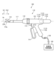
- FIG. 2 is a diagram showing a schematic configuration of a treatment system connected to the endoscope system according to the first embodiment.
- FIG. 3 is a block diagram showing a functional configuration of a main part of the endoscope system according to the first embodiment.
- FIG. 4 is a diagram illustrating the wavelength characteristics of light emitted by the first and second light source units according to the first embodiment.
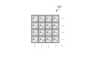
- FIG. 5 is a diagram illustrating a schematic configuration of a pixel unit according to the first embodiment.
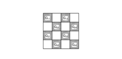
- FIG. 6 is a diagram illustrating a schematic configuration of a color filter according to the first embodiment.
- FIG. 7 is a diagram showing a schematic diagram of the sensitivity characteristics of each filter.
- FIG. 1 is a diagram showing a schematic configuration of an endoscope system according to a first embodiment.
- FIG. 2 is a diagram showing a schematic configuration of a treatment system connected to the endoscope system according to the
- FIG. 8A is a diagram illustrating signal values of R pixels of the image sensor according to the first embodiment.
- FIG. 8B is a diagram illustrating signal values of G pixels of the image sensor according to the first embodiment.
- FIG. 8C is a diagram illustrating a signal value of a B pixel of the image sensor according to the first embodiment.
- FIG. 9 is a diagram illustrating a schematic configuration of the cut filter according to the first embodiment.
- FIG. 10 is a diagram illustrating a transmission characteristic of the cut filter according to the first embodiment.
- FIG. 11 is a diagram illustrating the observation principle in the normal light observation mode according to the first embodiment.
- FIG. 12 is a diagram illustrating the observation principle in the thermal treatment observation mode according to the first embodiment.
- FIG. 13 is a flowchart for explaining a thermally altered region determination process using the endoscope system according to the first embodiment.
- FIG. 14 is a diagram for explaining a fluorescent image in the fluorescent observation mode.
- FIG. 15 is a flowchart for explaining a thermally altered region determination process using an endoscope system according to a modified example of the first embodiment.
- FIG. 16 is a diagram showing a schematic configuration of an endoscope system according to the second embodiment.
- FIG. 17 is a block diagram showing a functional configuration of a main part of an endoscope system according to the second embodiment.
- FIG. 18 is a diagram showing a schematic configuration of a surgical microscope system according to the third embodiment.
- FIG. 1 is a diagram showing a schematic configuration of an endoscope system according to a first embodiment.
- the endoscope system 1 shown in Fig. 1 is used in the medical field and is a system for observing biological tissue in a subject such as a living organism.
- the endoscope system 1 is used when performing surgery or treatment on a subject using a treatment tool (not shown) such as an energy device capable of thermal treatment.
- a treatment tool such as an energy device capable of thermal treatment.
- An operator performs surgery or treatment while observing a display device on which an observation image based on image data captured by a medical imaging device is displayed.
- the endoscope system 1 includes an insertion section 2, a light source device 3, a light guide 4, an endoscopic camera head 5 (medical imaging device), a first transmission cable 6, a display device 7, a second transmission cable 8, a control device 9, and a third transmission cable 10.
- the insertion section 2 is hard or at least partially soft and has an elongated shape.
- the insertion section 2 is inserted into a subject such as a patient via a trocar.
- the insertion section 2 is provided with an optical system such as a lens that forms an observation image inside.
- the light source device 3 is connected to one end of the light guide 4, and supplies illumination light to be irradiated into the subject at one end of the light guide 4 under the control of the control device 9.
- the light source device 3 is realized using one or more light sources, such as an LED (Light Emitting Diode) light source, a xenon lamp, and a semiconductor laser element such as an LD (laser diode), a processor which is a processing device having hardware such as an FPGA (Field Programmable Gate Array) and a CPU (Central Processing Unit), and a memory which is a temporary storage area used by the processor.
- One end of the light guide 4 is detachably connected to the light source device 3, and the other end is detachably connected to the insertion section 2.
- the light guide 4 guides the illumination light supplied from the light source device 3 from one end to the other, and supplies it to the insertion section 2.
- the endoscopic camera head 5 is detachably connected to the eyepiece 21 of the insertion section 2. Under the control of the control device 9, the endoscopic camera head 5 receives the observation image formed by the insertion section 2 and performs photoelectric conversion to generate an imaging signal (RAW data), and outputs this imaging signal to the control device 9 via the first transmission cable 6.
- RAW data an imaging signal
- the first transmission cable 6 transmits the imaging signal output from the endoscopic camera head 5 to the control device 9, and also transmits setting data, power, etc. output from the control device 9 to the endoscopic camera head 5.
- the setting data refers to a control signal, synchronization signal, clock signal, etc. that controls the endoscopic camera head 5.
- the display device 7 displays an observation image based on an imaging signal that has been subjected to image processing in the control device 9, and various information related to the endoscope system 1.
- the display device 7 is realized using a display monitor such as a liquid crystal or organic EL (Electro Luminescence) display.
- the second transmission cable 8 transmits the image signal that has been subjected to image processing in the control device 9 to the display device 7.
- the control device 9 is realized using a processor, which is a processing device having hardware such as a GPU (Graphics Processing Unit), FPGA, or CPU, and a memory, which is a temporary storage area used by the processor.
- the control device 9 comprehensively controls the operation of the light source device 3, the endoscopic camera head 5, and the display device 7 via each of the first transmission cable 6, the second transmission cable 8, and the third transmission cable 10 according to a program recorded in the memory.
- the control device 9 also performs various image processing on the imaging signal input via the first transmission cable 6 and outputs the signal to the second transmission cable 8.
- the third transmission cable 10 has one end detachably connected to the light source device 3 and the other end detachably connected to the control device 9.
- the third transmission cable 10 transmits control data from the control device 9 to the light source device 3.
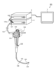
- Fig. 2 is a diagram showing a schematic configuration of the treatment system connected to the endoscope system according to embodiment 1.
- one side along the central axis Ax of the treatment tool is described as a distal end side Ar1, and the other side is described as a proximal end side Ar2.
- the treatment system 100 applies ultrasonic energy and high frequency energy to a portion of biological tissue that is to be treated (hereinafter referred to as the target portion) to treat the target portion.
- Treatments that can be performed by the treatment system according to this embodiment include treatments that coagulate and seal the target portion, treatments that cut the target portion, and treatments that simultaneously coagulate and cut the portion.
- the treatment system 100 includes a treatment tool 110 and a treatment tool control device 120.
- the treatment tool 110 is an ultrasonic treatment tool that applies ultrasonic energy and high-frequency energy to a target site to treat the target site, and corresponds to the surgical apparatus according to the present invention.
- the treatment tool 110 includes a handpiece 111 and an ultrasonic transducer 112.
- the handpiece 111 includes a holding case 113 , a movable handle 114 , a switch 115 , a rotating knob 116 , a pipe 117 , a jaw 118 , and a vibration transmission member 119 .
- the ultrasonic transducer 112 includes a TD (transducer) case 112a and an ultrasonic vibrator 112b.
- the TD case 112a supports the ultrasonic transducer 112b and is detachably connected to the holding case main body 113a.
- the ultrasonic transducer 112b generates ultrasonic vibrations under the control of the treatment tool control device 120.
- the ultrasonic transducer 112b is configured by a BLT (bolt-tightened Langevin type transducer).
- the holding case 113 constitutes the external appearance of the treatment tool 110 and supports the entire treatment tool 110.
- the holding case 113 includes a substantially cylindrical holding case main body 113a that is coaxial with the central axis Ax, and a fixed handle 113b that extends downward in FIG. 2 from the main body of the holding case 113 and is held by an operator such as a surgeon.
- the movable handle 114 receives an opening/closing operation by an operator such as a surgeon.
- the opening/closing operation is an operation for opening and closing the jaw 118 relative to the end portion 119a of the distal end side Ar1 of the vibration transmission member 119.
- the switch 115 is provided in a state where it is exposed to the outside from a side surface of the distal end side Ar1 of the fixed handle 113b.
- the switch 115 receives a treatment operation by an operator such as a surgeon.
- the treatment operation is an operation of applying ultrasonic energy or high frequency energy to a target site.
- an operation instruction is assigned to each button.
- the rotating knob 116 has a generally cylindrical shape that is coaxial with the central axis Ax, and is provided on the tip side Ar1 of the holding case main body 113a.
- the rotating knob 116 is rotated by an operator such as a surgeon. This rotation causes the rotating knob 116 to rotate around the central axis Ax relative to the holding case main body 113a. Furthermore, the rotation of the rotating knob 116 causes the pipe 117, jaw 118, and vibration transmission member 119 to rotate around the central axis Ax.
- the pipe 117 is a cylindrical pipe.
- a pin (not shown) that rotatably supports the jaw 118 is fixed to the end of the tip side Ar1 of the pipe 117.
- the jaw 118 is at least partially made of a conductive material. In response to an operator such as a surgeon gripping the movable handle 114, the jaw 118 opens and closes with respect to the end 119a on the tip side Ar1 of the vibration transmission member 119, and grips the target area between the jaw 118 and the end 119a.
- the vibration transmission member 119 is made of a conductive material and has an elongated shape that extends linearly along the central axis Ax.
- the vibration transmission member 119 is inserted into the pipe 117 with the end 119a of the tip side Ar1 protruding outward.
- the end of the base side Ar2 of the vibration transmission member 119 is mechanically connected to the ultrasonic transducer 112, although not specifically shown in the figure.
- the vibration transmission member 12 transmits the ultrasonic vibration generated by the ultrasonic transducer 112 from the end of the base side Ar2 to the end 119a of the tip side Ar1.
- the ultrasonic vibration is a longitudinal vibration that vibrates in a direction along the central axis Ax.
- the treatment tool control device 120 comprehensively controls the operation of the treatment tool 110 via an electric cable 130 .
- the treatment tool control device 120 detects a treatment operation on the switch 115 by an operator such as a surgeon through the electric cable 130. Then, when the treatment tool control device 120 detects the treatment operation, it applies ultrasonic energy or high-frequency energy to a target site grasped between the jaw 118 and the end portion 119a of the distal end side Ar1 of the vibration transmission member 119 through the electric cable 130. That is, the treatment tool control device 120 treats the target site.
- the treatment tool control device 120 supplies driving power to the ultrasonic transducer 112b via the electric cable 130.
- This causes the ultrasonic transducer 112b to generate longitudinal vibrations (ultrasonic vibrations) that vibrate in a direction along the central axis Ax.
- the end 119a on the tip side Ar1 of the vibration transmission member 119 vibrates at a desired amplitude due to the longitudinal vibrations.
- ultrasonic vibrations are applied from the end 119a to the target area grasped between the jaw 118 and the end 119a. In other words, ultrasonic energy is applied to the target area from the end 119a.
- the treatment tool control device 120 supplies high-frequency power between the jaw 118 and the vibration transmission member 119 via the electric cable 130.
- a high-frequency current flows through the target area grasped between the jaw 118 and the end 119a of the tip side Ar1 of the vibration transmission member 119.
- high-frequency energy is applied to the target area.
- the treatment tool control device 120 is also connected to the control device 9 so that it can communicate with it, and when the switch 115 is pressed, it outputs a signal indicating that the switch has been pressed to the control device 3.
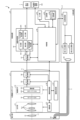
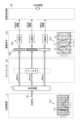
- Fig. 3 is a block diagram showing the functional configuration of the main parts of the endoscope system 1.
- the insertion portion 2 has an optical system 22 and an illumination optical system 23.
- the optical system 22 forms an image of the subject by collecting light such as reflected light from the subject, return light from the subject, excitation light from the subject, and light emitted by the subject.
- the optical system 22 is realized using one or more lenses, etc.
- the illumination optical system 23 irradiates the subject with illumination light supplied from the light guide 4.
- the illumination optical system 23 is realized using one or more lenses, etc.
- the light source device 3 includes a condenser lens 30, a first light source unit 31, a second light source unit 32, and a light source control unit 33.
- the focusing lens 30 focuses the light emitted by each of the first light source unit 31 and the second light source unit 32 and emits the light to the light guide 4.
- the first light source unit 31 emits visible white light (normal light) under the control of the light source control unit 33, thereby supplying the white light as illumination light to the light guide 4.
- the first light source unit 31 is configured using a collimator lens, a white LED lamp, a driving driver, etc.
- the first light source unit 31 may supply visible white light by simultaneously emitting light using a red LED lamp, a green LED lamp, and a blue LED lamp.
- the first light source unit 31 may also be configured using a halogen lamp, a xenon lamp, etc.
- the second light source unit 32 under the control of the light source control unit 33, emits narrowband light in a wavelength band different from and narrower than the white light, thereby supplying the narrowband light as illumination light to the light guide 4.
- the narrowband light is, for example, light in a wavelength band of 400 nm to 430 nm with a central wavelength of 415 nm.
- the second light source unit 32 is realized using a collimating lens, a semiconductor laser such as a violet LD (laser diode), a driving driver, and the like.
- the narrowband light functions as excitation light that excites advanced glycation endproducts generated by applying heat treatment to biological tissue.
- the light source control unit 33 is realized using a processor, which is a processing device having hardware such as an FPGA or a CPU, and a memory, which is a temporary storage area used by the processor.
- the light source control unit 33 controls the light emission timing and light emission time of each of the first light source unit 31 and the second light source unit 32 based on control data input from the control device 9.
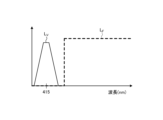
- FIG. 4 is a diagram showing the wavelength characteristics of the light emitted by each of the first light source unit 31 and the second light source unit 32.
- the horizontal axis indicates the wavelength (nm), and the vertical axis indicates the relative intensity.
- the curve L WL indicates the wavelength characteristics of the white light emitted by the first light source unit 31
- the curve L V indicates the wavelength characteristics of the narrow band light (excitation light) emitted by the second light source unit 32.
- the second light source unit 32 emits light having a central wavelength (peak wavelength) of 415 nm and including a wavelength band of 400 nm to 430 nm. Note that the wavelength characteristics shown by the curve L WL in FIG. 4 indicate the characteristics when a white LED is adopted as the first light source unit 31.
- the endoscopic camera head 5 includes an optical system 51, a drive unit 52, an image sensor 53, a cut filter 54, an A/D conversion unit 55, a P/S conversion unit 56, an image capture recording unit 57, and an image capture control unit 58.
- the optical system 51 forms an image of the subject collected by the optical system 22 of the insertion part 2 on the light receiving surface of the image sensor 53.
- the optical system 51 is capable of changing the focal length and focal position.
- the optical system 51 is configured using a plurality of lenses 511.
- the optical system 51 changes the focal length and focal position by moving each of the plurality of lenses 511 on the optical axis L1 using the drive part 52.
- the driving unit 52 moves the multiple lenses 511 of the optical system 51 along the optical axis L1 under the control of the imaging control unit 58.
- the driving unit 52 is configured using a motor such as a stepping motor, a DC motor, or a voice coil motor, and a transmission mechanism such as a gear that transmits the rotation of the motor to the optical system 51.
- the imaging element 53 is realized by using a CCD (Charge Coupled Device) or CMOS (Complementary Metal Oxide Semiconductor) image sensor having multiple pixels arranged in a two-dimensional matrix. Under the control of the imaging control unit 58, the imaging element 53 receives the subject image (light rays) formed by the optical system 51 through the cut filter 54, performs photoelectric conversion to generate an imaging signal (RAW data), and outputs it to the A/D conversion unit 55.
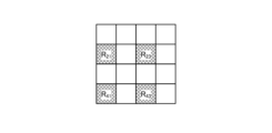
- the imaging element 53 has a pixel unit 531 and a color filter 532.
- the pixel unit 531 is a diagram showing a schematic configuration of the pixel unit 531.
- the pixel unit 531 is configured by arranging a plurality of pixels P nm (n and m are integers of 1 or more) such as photodiodes that accumulate electric charges according to the amount of light in a two-dimensional matrix.
- the imaging control unit 58 the pixel unit 531 reads out image signals as image data from pixels P nm in a readout region arbitrarily set as a readout target among the plurality of pixels P nm , and outputs the image signals to the A/D conversion unit 55.
- Fig. 6 is a diagram showing a schematic configuration of the color filter 532.
- the color filter 532 is configured in a Bayer array with 2 x 2 as one unit.
- the color filter 532 is configured using a filter R that transmits light in the red wavelength band, two filters G that transmit light in the green wavelength band, and a filter B that transmits light in the blue wavelength band.
- the reference numerals (e.g. G11 ) attached to each filter in Fig. 5 correspond to the pixel Pnm , and indicate that the filter is disposed at the corresponding pixel position.
- Fig. 7 is a diagram showing the sensitivity characteristics of each filter.
- the horizontal axis indicates wavelength (nm) and the vertical axis indicates transmission characteristics (sensitivity characteristics).
- a curve L- B indicates the transmission characteristics of filter B
- a curve L- G indicates the transmission characteristics of filter G
- a curve L- R indicates the transmission characteristics of filter R.
- Filter B transmits light in the blue wavelength band (see curves L to B in FIG. 7).
- Filter G transmits light in the green wavelength band (see curves L to G in FIG. 7).
- Filter R transmits light in the red wavelength band (see curves L to R in FIG. 7).
- a pixel P nm having filter R disposed on its light receiving surface is referred to as an R pixel
- a pixel P nm having filter G disposed on its light receiving surface is referred to as a G pixel
- a pixel P nm having filter B disposed on its light receiving surface is referred to as a B pixel.
- the image sensor 53 configured in this manner receives the subject image formed by the optical system 51, it generates color signals (R signal, G signal, and B signal) for the R pixel, G pixel, and B pixel, respectively (see Figures 8A to 8C).
- the cut filter 54 is disposed on the optical axis L1 between the optical system 51 and the image sensor 53.
- the cut filter 54 is provided on the light receiving surface side (incident surface side) of the G pixel on which the filter G that transmits at least the green wavelength band of the color filter 532 is provided.
- the cut filter 54 blocks light in the wavelength band of the excitation light and transmits a wavelength band longer in wavelength than the wavelength band of the excitation light.
- Fig. 9 is a diagram showing a schematic configuration of the cut filter 54. As shown in Fig. 9, the filter F11 constituting the cut filter 54 is disposed at the position where the filter G11 (see Fig. 6) is disposed, on the light receiving surface side directly above the filter G11 .
- Fig. 10 is a diagram showing a schematic diagram of the transmission characteristic of the cut filter 54.
- the horizontal axis indicates wavelength (nm) and the vertical axis indicates the transmission characteristic.
- a curve L- F indicates the transmission characteristic of the cut filter 54
- a curve L- V indicates the wavelength characteristic of the excitation light.
- the cut filter 54 blocks the wavelength band of the excitation light and transmits a wavelength band longer than the wavelength band of the excitation light. Specifically, the cut filter 54 blocks light in a wavelength band equal to or shorter than the wavelength band of the excitation light and transmits light in a wavelength band longer than the wavelength band of the excitation light.
- the A/D conversion unit 55 under the control of the imaging control unit 58, performs A/D conversion processing on the analog imaging signal input from the imaging element 53 and outputs the result to the P/S conversion unit 56.
- the A/D conversion unit 55 is realized using an A/D conversion circuit or the like.
- the P/S conversion unit 56 performs parallel/serial conversion on the digital imaging signal input from the A/D conversion unit 55 under the control of the imaging control unit 58, and outputs the parallel/serial converted imaging signal to the control device 9 via the first transmission cable 6.
- the P/S conversion unit 56 is realized using a P/S conversion circuit or the like. Note that in the first embodiment, instead of the P/S conversion unit 56, an E/O conversion unit that converts the imaging signal into an optical signal may be provided and the imaging signal may be output to the control device 9 by the optical signal, or the imaging signal may be transmitted to the control device 9 by wireless communication such as Wi-Fi (Wireless Fidelity) (registered trademark).
- Wi-Fi Wireless Fidelity
- the imaging and recording unit 57 records various information related to the endoscopic camera head 5 (e.g., pixel information of the imaging element 53, characteristics of the cut filter 54).
- the imaging and recording unit 57 also records various setting data and control parameters transmitted from the control device 9 via the first transmission cable 6.
- the imaging and recording unit 57 is configured using a non-volatile memory and a volatile memory.
- the imaging control unit 58 controls the operation of each of the drive unit 52, the imaging element 53, the A/D conversion unit 55, and the P/S conversion unit 56 based on the setting data received from the control device 9 via the first transmission cable 6.
- the imaging control unit 58 is realized using a TG (Timing Generator), a processor which is a processing device having hardware such as a CPU, and a memory which is a temporary storage area used by the processor.
- the control device 9 includes an S/P conversion unit 91 , an image processing unit 92 , an input unit 93 , a recording unit 94 , and a control unit 95 .
- the S/P conversion unit 91 Under the control of the control unit 95, the S/P conversion unit 91 performs serial/parallel conversion on the image data received from the endoscopic camera head 5 via the first transmission cable 6 and outputs the converted data to the image processing unit 92. If the endoscopic camera head 5 outputs an imaging signal as an optical signal, the S/P conversion unit 91 may be replaced by an O/E conversion unit that converts the optical signal into an electrical signal. If the endoscopic camera head 5 transmits an imaging signal via wireless communication, the S/P conversion unit 91 may be replaced by a communication module capable of receiving wireless signals.
- the image processing unit 92 Under the control of the control unit 95, the image processing unit 92 performs predetermined image processing on the imaging signal of parallel data input from the S/P conversion unit 91 and outputs the result to the display device 7.
- the predetermined image processing includes demosaic processing, white balance processing, gain adjustment processing, gamma correction processing, and format conversion processing.
- the image processing unit 92 is realized using a processor, which is a processing device having hardware such as a GPU or FPGA, and a memory, which is a temporary storage area used by the processor.
- the image processing unit 92 has a generation unit 921, an extraction unit 922, a fluorescent region determination unit 923, an output state determination unit 924, and an output unit 925.
- the generating unit 921 generates a first image including one or more characteristic regions that need to be excised by the surgeon, and a second image including one or more cauterized regions that have been cauterized by the energy device (treatment tool 110). Specifically, the generating unit 921 generates a white light image, which is the first image, based on an imaging signal generated by capturing reflected light and return light from the biological tissue when white light is irradiated onto the biological tissue. The generating unit 921 also generates a fluorescent image, which is the second image, based on an imaging signal generated by capturing fluorescence generated by excitation light irradiated to excite advanced glycation endproducts that are generated by subjecting the biological tissue to thermal treatment in a fluorescence observation mode described later.
- the generating unit 921 may generate a pseudo-color image, which is a pseudo-color image including one or more characteristic regions (lesion regions) that need to be excised by the surgeon, based on an imaging signal generated by capturing reflected light and return light from the biological tissue when excitation light is irradiated onto the biological tissue in a fluorescence observation mode of the endoscope system 1 described later.
- the extraction unit 922 extracts a fluorescent region, which is the region of the fluorescent image, from the fluorescent image generated by the generation unit 921.
- the fluorescent region determination unit 923 determines whether there is a change in the fluorescent region between fluorescent images captured at different times.
- the output state determination unit 924 determines the output state of the treatment tool 110 based on a signal received by the control device 3 from the treatment tool control device 120. Specifically, the output state determination unit 924 determines whether the output of the treatment tool 110 is in an ON state or an OFF state. Based on the determination results of the fluorescent region determination section 923 and the output state determination section 924, the control section 95 sets the corresponding fluorescent region to a thermally denatured region that occurs when the output of the energy device (treatment tool 110) is off (off-time generated fluorescent region).
- the output unit 925 outputs the white light image, the fluorescent image, the determination result of the fluorescent region determination unit 923, the setting information set by the control unit 95, etc.
- the input unit 93 receives inputs of various operations related to the endoscope system 1 and outputs the received operations to the control unit 95.
- the input unit 93 is configured using a mouse, a foot switch, a keyboard, buttons, switches, a touch panel, etc.
- the recording unit 94 is realized using a recording medium such as a volatile memory, a non-volatile memory, an SSD (Solid State Drive), an HDD (Hard Disk Drive), a memory card, etc.
- the recording unit 94 records data including various parameters necessary for the operation of the endoscope system 1.
- the recording unit 94 also has a program recording unit 941 that records various programs for operating the endoscope system 1.
- the control unit 95 is realized using a processor, which is a processing device having hardware such as an FPGA or a CPU, and a memory, which is a temporary storage area used by the processor.
- the control unit 95 comprehensively controls each component that constitutes the endoscope system 1.
- the control unit 95 also receives a signal from the treatment tool control device 120 regarding pressing of the switch 115 (output of the treatment tool 110).
- Fig. 11 is a schematic diagram showing the observation principle in the normal light observation mode.
- the light source device 3 emits light from the first light source unit 31, irradiating the living tissue T1 of the subject with white light W1 having the intensity distribution shown in graph G11.
- the reflected light and return light reflected by the living tissue (hereinafter simply referred to as "reflected light WR10, reflected light WG10, and reflected light WB10") are partially blocked by the cut filter 54, and the rest enter the image sensor 53.
- the cut filter 54 blocks the reflected light (reflected light WG10) that enters the G pixel and that is reflected light in the wavelength band of the excitation light (excitation light W2 described later).
- the reflected light and return light based on the irradiation of white light enter the filter R and the filter B, and light in a wavelength band longer than the wavelength band of the excitation light enters the filter G. Therefore, the component of light in the blue wavelength band that enters the pixel becomes smaller than in a state in which the cut filter 54 is not arranged.
- Light incident on each filter is selectively transmitted according to the filter characteristics shown in graph G12.
- the image processor 92 acquires image data (RAW data) from the imaging element 53 of the endoscopic camera head 5, and performs image processing on the signal values of each of the R, G, and B pixels contained in the acquired image data to generate a white light image.
- the image processor 92 performs white balance adjustment processing to adjust the white balance so that the ratio of the red, green, and blue components is constant.
- a natural white light image (observation image) can be observed even when a cut filter 54 is placed on the light receiving surface side of the G pixel.
- minimally invasive treatments using endoscopes and laparoscopes have become widely used in the medical field.
- minimally invasive treatments using endoscopes and laparoscopes include endoscopic submucosal dissection (ESD), laparoscopy and endoscopic cooperative surgery (LECS), non-exposed endoscopic wall-inversion surgery (NEWS), and transurethral resection of the bladder tumor (TUR-bt).
- a doctor or other surgeon may use an energy device treatment tool that emits high-frequency, ultrasonic, microwave, or other energy to perform a heat treatment, mark the area to be operated on as a pre-treatment, or excise the affected area, seal the incision, or coagulate the area as a treatment.
- an energy device treatment tool that emits high-frequency, ultrasonic, microwave, or other energy to perform a heat treatment, mark the area to be operated on as a pre-treatment, or excise the affected area, seal the incision, or coagulate the area as a treatment.
- AGEs are known to contain substances with fluorescent properties as a characteristic feature. AGEs are known to emit fluorescence with a higher intensity than the autofluorescent substances that are naturally present in living tissues. For this reason, the generation of AGEs causes a significant increase in the intensity of fluorescence compared to before the AGEs were produced.
- the fluorescence observation mode is an observation mode that visualizes the heat treatment area by utilizing the fluorescent properties of AGEs generated in the living tissue by heat treatment with an energy device or the like. For this reason, the fluorescence observation mode irradiates the living tissue with excitation light for exciting AGEs from the light source device 3, for example, narrowband blue light with a central wavelength of 415 nm. As a result, the fluorescence observation mode makes it possible to observe a heat treatment image (fluorescence image) obtained by capturing the fluorescence (for example, green light with a wavelength of 490 to 625 nm) generated from the AGEs.
- a heat treatment image fluorescence image
- the light source device 3 causes the second light source unit 32 to emit light, thereby irradiating excitation light W2 (center wavelength 415 nm: see graph G13) onto biological tissue T2 (thermal treatment area) where thermal treatment has been performed on the subject using an energy device or the like.
- reflected light hereinafter simply referred to as "reflected light WR20, reflected light WG20, reflected light WB20"
- reflected light WR20, reflected light WG20, reflected light WB20 including at least the component of excitation light W2 reflected by the biological tissue T2 (thermal treatment area) and return light
- the cut filter 54 a portion of the long-wavelength component enters the imaging element 53 (see graph G14).
- the strength of each line component is represented by the thickness of the arrow.
- the cut filter 54 blocks the reflected light WG20 incident on the G pixel, which is in a wavelength band including the wavelength band of the excitation light W2. Furthermore, the cut filter 54 transmits the fluorescence WF1 generated by the AGEs in the biological tissue T2 (thermal treatment area) (see graph G14). Therefore, the reflected light WG20 does not enter the G pixel, but the fluorescence WF1 does. Since the cut filter 54 is disposed on the light receiving surface side (incident surface side) of the G pixel, it is possible to prevent the reflected light WG20 of the excitation light W2 from mixing with the fluorescence WF1 and obscuring the fluorescent component. Furthermore, reflected light (WR20, WB20) and fluorescent light WF1 are incident on the R pixel and the B pixel, respectively.
- the image processing unit 92 acquires image data (RAW data) from the imaging element 53 of the endoscopic camera head 5, and performs image processing on the signal values of the G pixels and B pixels included in the acquired image data to generate a fluorescent image.
- the signal value of the G pixel includes fluorescent information indicating the fluorescent image emitted from the heat treatment area.
- the B pixel includes background information that is the biological tissue surrounding the heat treatment area and forms the background of the heat treatment area.
- the image processing unit 92 performs image processing such as gain control processing, pixel complement processing, and mucosa enhancement processing on the signal values of the G pixels and B pixels included in the image data to generate a fluorescent image.
- the image processing unit 92 performs processing to make the gain for the signal value of the G pixel larger than the gain for the signal value of the G pixel during normal light observation, while making the gain for the signal value of the B pixel smaller than the gain for the signal value of the B pixel during normal light observation. Furthermore, the image processing unit 92 performs processing to make the signal value of the G pixel and the signal value of the B pixel the same (1:1). The image processing unit 92 may also generate a pseudo-color image by superimposing color information, the hue of which is changed according to the fluorescence intensity, on the fluorescent image.
- the surgeon performs treatment on the subject's treatment target while checking the white light image displayed on the display device 7. For example, the surgeon cauterizes and removes the treatment target using an energy device (treatment tool 110) inserted into the subject via the insertion portion 2.
- treatment tool 110 an energy device
- the surgeon irradiates the treatment target with excitation light and observes the fluorescent image displayed by the display device 7.
- the surgeon determines whether or not the treatment (e.g., resection) at the treatment position has been completed. If the surgeon determines that the treatment has been completed, the surgeon ends the procedure. Specifically, the surgeon determines whether or not the resection of the treatment target has been completed by observing the fluorescent image displayed by the display device 7 and the area resected by cauterization using the treatment tool 110.
- the surgeon continues the treatment by switching the observation mode of the endoscope system 1, repeatedly observing the white light image obtained by irradiating the white light and the fluorescent image obtained by irradiating the excitation light.
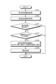
- Fig. 13 is a flowchart for explaining the thermally altered region determination processing using the endoscope system according to one embodiment.
- the thermally altered region determination processing is processing executed in the fluorescence observation mode.
- the control unit 95 generates a first fluorescence image (step S101). At this time, the control unit 95 controls the light source control unit 33 to cause the second light source unit 32 to emit light and irradiate the subject with excitation light.
- the generation unit 921 generates the first fluorescence image by acquiring an image signal from the image sensor 53 of the endoscopic camera head 5. In this way, the first fluorescence image is acquired. In this case, the output unit 925 may cause the display device 7 to display the first fluorescence image generated by the generation unit 921.
- the control unit 95 generates a second fluorescence image (step S102).
- the control unit 95 controls the light source control unit 33 to cause the second light source unit 32 to emit light and irradiate the subject with excitation light.
- the generation unit 921 generates the second fluorescence image by acquiring an imaging signal from the imaging element 53 of the endoscopic camera head 5. In this way, the second fluorescence image is acquired.
- the output unit 925 may cause the display device 7 to display the second fluorescence image generated by the generation unit 921.
- the second fluorescent image is a fluorescent image based on image data acquired at a later time than the first fluorescent image, and the image data is acquired (imaging timing) after a preset time has elapsed after the first fluorescent image is acquired, for example.
- the control unit 95 judges whether or not there is a change in the fluorescent region between the first fluorescent image and the second fluorescent image (step S103).
- the extraction unit 922 extracts the region (fluorescent region) in which the fluorescent image is depicted from each fluorescent image.
- the extraction unit 922 extracts one or more fluorescent regions included in the image by performing contour extraction based on, for example, a luminance value.
- the fluorescent region determination unit 923 judges whether or not there is a change in the fluorescent region of the second fluorescent image compared to the extracted fluorescent region of the first fluorescent image.
- the fluorescent region determination unit 923 detects the change in the fluorescent region by judging the presence or absence of a new fluorescent region that exists in the second fluorescent image but does not exist in the first fluorescent image.
- step S103 If the fluorescent region determination unit 923 judges that there is no change in the fluorescent region (step S103: No), the control unit 95 ends the process. On the other hand, if the fluorescent region determination unit 923 judges that there is a change in the fluorescent region (step S103: Yes), the control unit 95 proceeds to step S104.
- step S104 the control unit 95 judges whether the output state of the treatment tool is in the OFF state.
- the output state judgment unit 924 judges whether the treatment tool 110 is in the OFF state or the ON state when the second fluorescent image is captured. For example, the output state judgment unit 924 judges whether the output of the treatment tool 110 is ON/OFF at the time of capturing the second fluorescent image based on a signal from the treatment tool control device 120 received by the control device 3. Also, if information on the output of the treatment tool 110 is provided for each fluorescent image, the output state judgment unit 924 judges the ON/OFF state by referring to the information.
- step S104 If the output state judgment unit 924 judges that the output state of the treatment tool is ON, that is, not OFF (step S104: No), the control unit 95 ends the process. On the other hand, if the output state judgment unit 924 judges that the output state of the treatment tool is OFF (step S104: Yes), the control unit 95 proceeds to step S105.
- step S105 the control unit 95 sets the thermally altered region (new fluorescent region) added in the second fluorescent image to the thermally altered region that occurred when the output was off (fluorescent region generated when the output was off). At this time, the control unit 95 sets the fluorescent region that does not exist in the first fluorescent image, among the fluorescent regions extracted by the extraction unit 922 in the second fluorescent image, to the thermally altered region that occurred when the output was off.
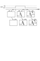
- Fig. 14 is a diagram for explaining the fluorescent image in the fluorescent observation mode.
- Fig. 14 shows an example in which the output of the treatment tool 110 is turned on at time t10 and turned off at time t11 .
- a fluorescent image FL11 corresponding to the AGEs is depicted (see image PI2). Therefore, when the fluorescent image at this time is displayed on the display device 7, a fluorescent image FL21 is displayed (see image PO2).
- This fluorescent image FL11 (FL21) corresponds to the AGEs generated by the energy applied from the treatment tool 110, for example.
- the fluorescent image FL11 and the fluorescent image FL21 may be displayed in the same hue, or, for example, the fluorescent image FL21 may be displayed with a pseudo color superimposed thereon.
- the treatment tool 110 with its output turned off comes into contact with the living tissue, generating new AGEs, and a fluorescent image FL12 corresponding to these AGEs is depicted (see image PI3). Therefore, when the fluorescent image at this time is displayed on the display device 7, a fluorescent image FL22 is displayed (see image PO3).
- This fluorescent image FL12 (FL21) corresponds to AGEs generated by, for example, residual heat of the treatment tool 110.
- This newly generated fluorescent image FL12 is detected as a change in the fluorescent region by the fluorescent region determination unit 923, and is set as the thermally altered region that occurred when the output was off.
- the fluorescent image FL22 displayed on the display device 7 may be given information that it was generated when the output was off, or a hue indicating that it was generated when the output was off may be superimposed.
- a display mode may be used in which only the thermally altered region that occurred after the output was off (fluorescent image FL22 in FIG. 14) is displayed to enable the user to grasp the thermally altered region.
- the control unit 95 executes a notification process for the thermally altered region that occurred when the output was off (step S106).
- the control unit 95 displays information on the display device 7 that a thermally altered region occurred when the output of the treatment tool 110 was off.
- the control unit 95 may display text information, etc., indicating that a new thermally altered region occurred when the output was off by arranging the fluorescent images of the comparison target, or may superimpose text information indicating that the region is a thermally altered region when the output was off, or a pseudo color, etc., that is assigned depending on whether the output was on or off, on the fluorescent region of interest on the second fluorescent image.
- the generation unit 921 generates the above-mentioned display image according to the conditions set for the notification process. It is also possible to display information corresponding to the fluorescent region on the white light image, or to notify the occurrence of a thermally altered region when the output was off by sound or light.
- the thermally altered region determination process is executed, for example, at a preset time interval or when an instruction to execute the detection process is input by the surgeon or the like.
- the second fluorescence image acquired during the previous process can be used as the first fluorescence image, and in that case, the process can start from step S102.
- the output state of the treatment tool at the time the fluorescent image in which the change occurred was captured is determined, and this newly generated fluorescent region is set as a fluorescent region equivalent to a thermally altered region that occurred when the output of the energy device was off (fluorescent region generated when the output was off), and the surgeon is notified.
- this first embodiment it is possible to make the surgeon aware of thermal alteration that occurred when the output of the treatment tool was off.
- the endoscope system according to the modified example is similar to the endoscope system 1 according to the embodiment, and therefore the description will be omitted.
- the thermally altered region may expand due to residual heat even after the treatment tool 110 is removed. In most cases, the region expanded due to residual heat is a thermally altered region that the surgeon is aware of, and therefore there is no need to set it as a new thermally altered region.
- an example will be described in which the region expanded due to residual heat is excluded from the new thermally altered region that occurs after the output is turned off.
- Fig. 17 is a flowchart for explaining a thermally altered region determination process performed by an endoscope system according to a modified example.
- the control unit 95 generates the first and second fluorescent images and detects changes in the fluorescent region in the same manner as in the embodiment (steps S201 to S203).
- step S203 determines whether the output state of the treatment tool is off (step S204) in the same manner as in step S104. At this time, if it is determined that the output of the treatment tool 110 is off at the time the second fluorescent image is captured (step S204: Yes), the process proceeds to step S205.
- step S205 the control unit 95 determines whether a predetermined time has passed since the treatment tool 110 was switched off. Specifically, the control unit 95 determines whether the capture time of the second fluorescent image is a time when a preset time has passed since the treatment tool 110 was switched off by pressing the switch 115. If the control unit 95 determines that the capture time of the second fluorescent image has not passed the predetermined time since the switch off time (step S205: No), the control unit 95 ends the process. On the other hand, if the control unit 95 determines that the capture time of the second fluorescent image has passed the predetermined time since the switch off time (step S205: No), the control unit 95 proceeds to step S206.
- step S206 the control unit 95 sets the thermally altered region added in the second fluorescent image to the thermally altered region that occurred when the output was off.
- control unit 95 executes a notification process for the thermally denatured region that occurred when the output was off (step S207). At this time, the control unit 95 displays information on the display device 7 that a thermally denatured region occurred when the output of the treatment tool 110 was off, in the same manner as in step S106.
- the output state of the treatment tool at the time the fluorescent image in which the change occurred was captured is determined, and if the output is off, the newly generated fluorescent region is set as a thermally altered region that occurred when the output of the energy device was off, and the surgeon is notified of this.
- This modified example allows the surgeon to be aware of thermal alteration that occurred when the output of the treatment tool was off.
- the changed fluorescent region is not set as a new thermally altered region, and therefore the region that has expanded due to residual heat immediately after treatment is excluded from the new thermally altered region that occurs after the output is turned off.
- the thermally altered region that the surgeon is believed to be aware of is excluded from the setting of the thermally altered region after the output is turned off, and the thermally altered region after the predetermined time has passed becomes the thermally altered region to be notified, so the surgeon can check only the thermally altered regions that he or she is not aware of, allowing for efficient treatment.
- a new fluorescent region after a predetermined time has elapsed since the treatment tool 110 was turned off is used to judge the thermally altered region that occurred when the output was off.
- the target for judgment may be set based on the expansion rate of the fluorescent region instead of the elapsed time.
- a threshold for the expansion rate of the region and a threshold for the change (difference) in the distance from the center of gravity of the region to the outer edge are set based on the size (way of spreading) of the fluorescent region that expands due to residual heat, and a judgment is made based on the threshold for whether or not to make it a target for judgment.
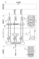
- Fig. 18 is a diagram showing a schematic configuration of an endoscope system according to embodiment 2.
- Fig. 19 is a block diagram showing a functional configuration of a main part of the endoscope system according to embodiment 2.
- the endoscope system 101 is inserted into a subject, such as a patient, to capture images of the inside of the subject's body, and the display device 7 displays an image based on the captured image data.
- An operator such as a doctor, examines the presence and condition of each of the abnormal areas that show bleeding sites, tumor sites, and abnormal sites, which are the areas to be examined, by observing the display image displayed by the display device 7.
- the operator such as a doctor, inserts a treatment tool, such as an energy device, into the subject's body via the treatment tool channel of the endoscope to treat the subject.
- the endoscope system 101 includes an endoscope 102 in addition to the light source device 3, display device 7, and control device 9 described above.
- the endoscope 102 generates image data by capturing an image of the inside of a subject's body, and outputs the generated image data to the control device 9.
- the endoscope 102 includes an operation unit 122 and a universal cord 123.
- the insertion section 121 has a flexible, elongated shape.
- the insertion section 121 has a tip section 124 with a built-in imaging device (described later), a freely bendable bending section 125 composed of multiple bending pieces, and a long, flexible tube section 126 connected to the base end side of the bending section 125.
- the tip portion 124 is constructed using glass fiber or the like.
- the tip portion 124 has a light guide 241 that forms a light guide path for the light supplied from the light source device 3, an illumination lens 242 provided at the tip of the light guide 241, and an imaging device 243.
- the imaging device 243 includes a focusing optical system 244, the imaging element 53 of the first embodiment described above, a cut filter 54, an A/D conversion unit 55, a P/S conversion unit 56, an imaging recording unit 57, and an imaging control unit 58.
- the universal cord 123 incorporates at least a light guide 241 and an assembly cable consisting of one or more cables.
- the assembly cable is a signal line for transmitting and receiving signals between the endoscope 102, the light source device 3, and the control device 9, and includes a signal line for transmitting and receiving setting data, a signal line for transmitting and receiving captured images (image data), and a signal line for transmitting and receiving a timing signal for driving the image sensor 53.
- the universal cord 123 has a connector section 127 that is detachable from the light source device 3.
- the connector section 127 has a coiled coil cable 127a extending therefrom, and has a connector section 128 at the extending end of the coil cable 127a that is detachable from the control device 9.
- the endoscope system 101 configured in this manner performs the same processing as the endoscope system 1 according to the first embodiment described above.
- the output state of the treatment tool at the time when the fluorescent image in which the change occurred was captured is determined, and if the output is off, the newly generated fluorescent region is set as a thermally altered region that occurred when the output of the energy device was off, and the surgeon is notified of this.
- the second embodiment it is possible to allow the surgeon to be aware of thermal alteration that occurred when the output of the treatment tool was off.
- Embodiment 3 Next, a description will be given of embodiment 3.
- an endoscope system is described, but in embodiment 3, a case where the system is applied to a surgical microscope system is described.
- embodiment 3 the same components as those in the endoscope system 1 according to the above-described embodiment 1 are denoted by the same reference numerals, and detailed description thereof will be omitted.
- FIG. 20 is a diagram showing a schematic configuration of a surgical microscope system according to embodiment 3.
- the surgical microscope system 300 includes a microscope device 310, which is a medical imaging device that captures and obtains images for observing a subject, and a display device 7. It is also possible to configure the display device 7 and the microscope device 310 as an integrated unit.
- the microscope device 310 has a microscope section 312 that magnifies and captures a minute part of the subject, a support section 313 that is connected to the base end of the microscope section 312 and includes an arm that rotatably supports the microscope section 312, and a base section 314 that rotatably holds the base end of the support section 313 and is movable on the floor surface.
- the base section 314 has a light source device 3 that generates white light, first narrowband light, second narrowband light, etc. to be irradiated from the microscope device 310 to the subject, and a control device 9 that controls the operation of the surgical microscope system 300.
- Each of the light source device 3 and the control device 9 has at least the same configuration as that of the above-mentioned embodiment 1.
- the light source device 3 has a condensing lens 30, a first light source section 31, a second light source section 32, and a light source control section 33.
- the control device 9 has an S/P conversion section 91, an image processing section 92, an input section 93, a recording section 94, and a control section 95.
- the base part 314 may be fixed to a ceiling or wall surface, etc., to support the support part 313, rather than being movably provided on the floor surface.
- the microscope section 312 is, for example, cylindrical and has the above-mentioned medical imaging device inside.
- the medical imaging device has a configuration similar to that of the endoscopic camera head 5 according to the above-mentioned embodiment 1.
- the microscope section 312 includes an optical system 51, a drive section 52, an image sensor 53, a cut filter 54, an A/D conversion section 55, a P/S conversion section 56, an image recording section 57, and an image control section 58.
- a switch is provided on the side of the microscope section 312 for receiving input of operation instructions for the microscope device 310.
- a cover glass (not shown) is provided on the opening surface at the lower end of the microscope section 312 to protect the inside.
- the shape of the microscope unit 312 is preferably elongated and extends in the observation direction so that the user can easily hold it and change the field of view.
- the shape of the microscope unit 312 may be other than cylindrical, and may be, for example, a polygonal prism.
- the surgical microscope system 300 determines the output state of the treatment tool at the time the fluorescent image in which the change occurred was captured, and if the output is off, the newly generated fluorescent region is set as a thermally altered region that occurred when the output of the energy device was off, and the surgeon is notified of this. According to the third embodiment, it is possible to allow the surgeon to be aware of thermal alteration that occurred when the output of the treatment tool was off.
- Various inventions can be formed by appropriately combining multiple components disclosed in the endoscope systems according to the first and second embodiments of the present disclosure or the surgical microscope system according to the third embodiment of the present disclosure. For example, some components may be deleted from all the components described in the endoscope systems or surgical microscope systems according to the embodiments of the present disclosure. Furthermore, the components described in the endoscope systems or surgical microscope systems according to the embodiments of the present disclosure may be appropriately combined. Furthermore, this embodiment can be applied to any processing based on fluorescence emitted by a substance generated by cauterization or the like.
- the processing example was explained on the assumption that the first and second fluorescent images are images with the same angle of view, but when using images with different angles of view that partially show the same subject, the fluorescent regions (thermally altered regions) are matched using a known method such as pattern matching, and changes in the fluorescent regions are detected, and processing is performed to set the thermally altered regions that have occurred after the output is turned off.
- the "unit” described above can be read as “means” or “circuit.”
- the control unit can be read as control means or control circuit.
- the programs executed by each device according to the first to third embodiments are provided as file data in an installable or executable format recorded on a computer-readable recording medium such as a CD-ROM, a flexible disk (FD), a CD-R, a DVD (Digital Versatile Disk), a USB medium, or a flash memory.
- a computer-readable recording medium such as a CD-ROM, a flexible disk (FD), a CD-R, a DVD (Digital Versatile Disk), a USB medium, or a flash memory.
- the programs executed by each device according to the first to third embodiments may be stored on a computer connected to a network such as the Internet and provided by downloading via the network. Furthermore, the programs executed by the information processing devices according to the first to third embodiments may be provided or distributed via a network such as the Internet.
- the light source device 3 is separate from the control device 9, but the light source device 3 and the control device 9 may be configured as an integrated unit.
- the light source device 3 is integrated with the control device 9, but the light source device 3 and the control device 9 may be configured as separate units.
- the medical device, medical system, medical device operation method, and medical device operation program of the present invention are useful for allowing the surgeon to understand the thermal degeneration that occurs when the output of the treatment tool is turned off.
Landscapes
- Health & Medical Sciences (AREA)
- Life Sciences & Earth Sciences (AREA)
- Surgery (AREA)
- Engineering & Computer Science (AREA)
- Physics & Mathematics (AREA)
- Animal Behavior & Ethology (AREA)
- Veterinary Medicine (AREA)
- Nuclear Medicine, Radiotherapy & Molecular Imaging (AREA)
- Public Health (AREA)
- General Health & Medical Sciences (AREA)
- Molecular Biology (AREA)
- Biomedical Technology (AREA)
- Heart & Thoracic Surgery (AREA)
- Medical Informatics (AREA)
- Optics & Photonics (AREA)
- Biophysics (AREA)
- Radiology & Medical Imaging (AREA)
- Pathology (AREA)
- Signal Processing (AREA)
- Plasma & Fusion (AREA)
- Otolaryngology (AREA)
- Endoscopes (AREA)
Abstract
Description
〔内視鏡システムの構成〕
図1は、実施の形態1に係る内視鏡システムの概略構成を示す図である。図1に示す内視鏡システム1は、医療分野に用いられ、生体等の被検体内の生体組織を観察するシステムである。内視鏡システム1は、熱処置が可能なエネルギーデバイス等の処置具(図示せず)を用いて被検体の手術や処置を行う際に用いられる。術者は、医療用撮像装置によって撮像された画像データに基づく観察画像が表示された表示装置を観察しながら手術や処置等を行う。
次に、上述した内視鏡システム1に接続する処置システム100の構成について説明する。図2は、実施の形態1に係る内視鏡システムに接続する処置システムの概略構成を示す図である。なお、図2では、処置具の中心軸Axに沿う一方側を先端側Ar1と記載し、他方側を基端側Ar2と記載する。
ハンドピース111は、保持ケース113と、可動ハンドル114と、スイッチ115と、回転ノブ116と、パイプ117と、ジョー118と、振動伝達部材119とを備える。
TDケース112aは、超音波振動子112bを支持するとともに、保持ケース本体113aに対して着脱自在に接続する。
超音波振動子112bは、処置具制御装置120による制御のもと、超音波振動を発生させる。本実施の形態では、超音波振動子112bは、BLT(ボルト締めランジュバン型振動子)によって構成されている。
可動ハンドル114は、術者等の操作者による開閉操作を受け付ける。当該開閉操作は、ジョー118を振動伝達部材119における先端側Ar1の端部119aに対して開閉させる操作である。
スイッチ115は、固定ハンドル113bにおける先端側Ar1の側面から外部に露出した状態で設けられている。そして、スイッチ115は、術者等の操作者による処置操作を受け付ける。当該処置操作は、対象部位に対して超音波エネルギや高周波エネルギを付与させる操作である。スイッチ115は、複数のボタンを有する場合、各ボタンに操作指示がそれぞれ割り当てられる。
具体的に、処置具制御装置120は、電気ケーブル130を経由することによって、術者等の操作者によるスイッチ115への処置操作を検知する。そして、処置具制御装置120は、当該処置操作を検知した場合には、電気ケーブル130を経由することによって、ジョー118と振動伝達部材119における先端側Ar1の端部119aとの間に把持された対象部位に対して超音波エネルギや高周波エネルギを付与する。すなわち、処置具制御装置120は、当該対象部位を処置する。
次に、上述した内視鏡システム1の要部の機能構成について説明する。図3は、内視鏡システム1の要部の機能構成を示すブロック図である。
まず、挿入部2の構成について説明する。挿入部2は、光学系22と、照明光学系23と、を有する。
次に、光源装置3の構成について説明する。光源装置3は、集光レンズ30と、第1の光源部31と、第2の光源部32と、光源制御部33とを備える。
図3に戻り、内視鏡システム1の構成の説明を続ける。
次に、内視鏡カメラヘッド5の構成について説明する。内視鏡カメラヘッド5は、光学系51と、駆動部52と、撮像素子53と、カットフィルタ54と、A/D変換部55と、P/S変換部56と、撮像記録部57と、撮像制御部58と、を備える。
カットフィルタ54は、光学系51と撮像素子53との光軸L1上に配置される。カットフィルタ54は、少なくともカラーフィルタ532の緑色の波長帯域を透過するフィルタGが設けられたG画素の受光面側(入射面側)に設けられる。カットフィルタ54は、励起光の波長帯域の光を遮光し、該励起光の波長帯域よりも長波長側の波長帯域を透過する。
カットフィルタ54は、励起光の波長帯域を遮光し、励起光の波長帯域から長波長側の波長帯域を透過する。具体的には、カットフィルタ54は、励起光の波長帯域以下の波長帯域の光を遮光し、かつ、該励起光よりも長波長側の波長帯域の光を透過する。
A/D変換部55は、撮像制御部58による制御のもと、撮像素子53から入力されたアナログの撮像信号に対してA/D変換処理を行ってP/S変換部56へ出力する。A/D変換部55は、A/D変換回路等を用いて実現される。
次に、制御装置9の構成について説明する。
制御装置9は、S/P変換部91と、画像処理部92と、入力部93と、記録部94と、制御部95と、を備える。
制御部95は、蛍光領域判定部923および出力状態判定部924の判定結果に基づいて、該当する蛍光領域に対し、エネルギーデバイス(処置具110)の出力がオフのときに発生した熱変性領域(オフ時生成蛍光領域)に設定する。
次に、内視鏡システム1が実行可能な各観察モードの概要について説明する。なお、以下においては、通常光観察モード、蛍光観察モードの順に説明する。
まず、通常光観察モードについて説明する。図11は、通常光観察モード時における観察原理を模式的に示す図である。
次に、蛍光観察モードについて説明する。図12は、蛍光観察モード時における観察原理を模式的に示す図である。
すなわち、蛍光観察モードは、エネルギーデバイス等によって熱処置されることで生体組織中に発生したAGEsの蛍光特性を利用して、熱処置領域を可視化する観察モードである。このため、蛍光観察モードは、光源装置3からAGEsを励起させるための励起光、例えば415nmを中心波長とする青色の狭帯域光を生体組織に照射する。これにより、蛍光観察モードは、AGEsから発生する蛍光(例えば、波長490~625nmの緑色光)を撮像した熱処置画像(蛍光画像)を観察することができる。
また、R画素およびB画素には、反射光(反射光WR20、WB20)および蛍光WF1がそれぞれ入射する。
次に、本開示の内視鏡システム1を用いた処置について説明する。この際、術者は、被検体に挿入部2を挿入し、光源装置3に白色光を被検体内に照射させ、処置対象を含む領域に白色光を照射する。術者は、表示装置7が表示する観察画像を観察しながら処置対象を確認する。
次に、内視鏡システム1が実行する処理について説明する。図13は、一実施の形態に係る内視鏡システムを用いた熱変性領域判定処理を説明するためのフローチャートである。熱変性領域判定処理は、蛍光観察モード時に実行される処理である。
第2蛍光画像は、第1蛍光画像よりも後の時刻に取得された画像データに基づく蛍光画像である。画像データの取得時刻(撮像タイミング)については、例えば、第1蛍光画像取得後、予め設定した時間経過後に実行される。
なお、蛍光像FL11と、蛍光像FL21とは、互いに同じ色相で表示してもよいし、例えば蛍光像FL21に疑似カラーを重畳して表示してもよい。
この新たに発生した蛍光像FL12が、蛍光領域判定部923によって蛍光領域の変化として検出され、出力オフ時に発生した熱変性領域に設定される。表示装置7に表示される蛍光像FL22は、出力オフ時に発生した旨の情報が付与されたり、出力オフ時に発生したことを示す色相が重畳されたりする。また、出力オフ後に発生した熱変性領域(図14では蛍光像FL22)のみを表示して、当該熱変性領域を把握させる表示態様としてもよい。
次に、実施の形態1の変形例について、図15を参照して説明する。変形例に係る内視鏡システムは、実施の形態にかかる内視鏡システム1と同様であるため、説明を省略する。熱変性領域は、処置具110が離れた後でも、余熱によって領域が拡大することがある。この余熱によって拡大した領域は、術者が把握している熱変性領域であることがほとんどであるため、新たな熱変性領域に設定する必要がない。変形例では、この余熱によって拡大した領域を、出力オフ後に発生した新たな熱変性領域から除外する例について説明する。
次に、変形例に係る内視鏡システムが実行する処理について説明する。図17は、変形例に係る内視鏡システムを用いた熱変性領域判定処理を説明するためのフローチャートである。
次に、実施の形態2について説明する。上述した実施の形態1では、硬性鏡を備える内視鏡システムであったが、実施の形態2では、軟性の内視鏡を備える内視鏡システムについて説明する。以下においては、実施の形態2に係る内視鏡システムについて説明する。なお、実施の形態2では、上述した実施の形態1に係る内視鏡システム1と同一の構成には同一の符号を付しており、詳細な説明は省略する。
図18は、実施の形態2に係る内視鏡システムの概略構成を示す図である。図19は、実施の形態2に係る内視鏡システムの要部の機能構成を示すブロック図である。
内視鏡102の構成について説明する。内視鏡102は、被検体の体内を撮像することによって画像データを生成し、この生成した画像データを制御装置9へ出力する。内視鏡102は、操作部122と、ユニバーサルコード123とを備える。
次に、実施の形態3について説明する。上述した実施の形態1、2では、内視鏡システムであったが、実施の形態3では、手術用顕微鏡システムに適用した場合について説明する。なお、実施の形態3では、上述した実施の形態1に係る内視鏡システム1と同一の構成には同一の符号を付しており、詳細な説明は省略する。
図20は、実施の形態3に係る手術用顕微鏡システムの概略構成を示す図である。手術用顕微鏡システム300は、被写体を観察するための画像を撮像することによって取得する医療用撮像装置である顕微鏡装置310と、表示装置7と、を備える。なお、表示装置7と顕微鏡装置310とを一体に構成することも可能である。
上述した本開示の実施の形態1、2に係る内視鏡システムまたは実施の形態3に係る手術用顕微鏡システムに開示されている複数の構成要素を適宜組み合わせることによって、種々の発明を形成することができる。例えば、上述した本開示の実施の形態に係る内視鏡システムまたは手術用顕微鏡システムに記載した全構成要素からいくつかの構成要素を削除してもよい。さらに、上述した本開示の実施の形態に係る内視鏡システムまたは手術用顕微鏡システムで説明した構成要素を適宜組み合わせてもよい。さらに、本実施の形態は、焼灼等によって発生した物質が発する蛍光に基づいて処理するものであれば適用できる。
2 挿入部
3 光源装置
4 ライトガイド
5 内視鏡カメラヘッド
6 第1の伝送ケーブル
7 表示装置
8 第2の伝送ケーブル
9、9A 制御装置
10 第3の伝送ケーブル
21 接眼部
22 光学系
23 照明光学系
30 集光レンズ
31 第1の光源部
32 第2の光源部
33 光源制御部
51 光学系
52 駆動部
53 撮像素子
54 カットフィルタ
55 A/D変換部
56 P/S変換部
57 撮像記録部
58 撮像制御部
61 ビデオコネクタ
62 カメラヘッドコネクタ
91 S/P変換部
92 画像処理部
93 入力部
94 記録部
95 制御部
100 処置システム
102 内視鏡
110 処置具
115 スイッチ
120 処置具制御装置
121 挿入部
122 操作部
123 ユニバーサルコード
124 先端部
125 湾曲部
126 可撓管部
127、128 コネクタ部
127a コイルケーブル
130 電気ケーブル
241 ライトガイド
242 照明レンズ
243 撮像装置
244 光学系
300 手術用顕微鏡システム
310 顕微鏡装置
312 顕微鏡部
313 支持部
314 ベース部
511 レンズ
531 画素部
532 カラーフィルタ
921 生成部
922 抽出部
923 蛍光領域判定部
924 出力状態判定部
925 出力部
941 プログラム記録部
Claims (14)
- エネルギーデバイスを用いた焼灼によって生じる物質を励起する励起光によって発生する蛍光に基づく蛍光画像を生成する生成部と、
前記エネルギーデバイスの出力情報、および、前記蛍光画像に基づいて、当該エネルギーデバイスの出力がオフ状態の期間に発生したオフ時生成蛍光領域を判定する蛍光領域判定部と、
前記蛍光領域判定部によって前記オフ時生成蛍光領域であると判定された場合に、前記エネルギーデバイスの出力がオフ状態の期間における蛍光領域の発生を報知する報知処理を実行する制御部と、
を備える医療用装置。 - 前記生成部は、第1蛍光画像、および、前記第1蛍光画像とは撮像時刻が後の第2蛍光画像を生成し、
蛍光領域判定部は、前記第1蛍光画像および前記第2蛍光画像に基づいて、前記第2蛍光画像のみに存在する新規蛍光領域の有無を判定し、前記新規蛍光領域が存在する場合に、前記エネルギーデバイスの出力情報に基づいて、当該新規蛍光領域が前記オフ時生成蛍光領域に該当するか否かを判定する、
請求項1に記載の医療用装置。 - 前記第1蛍光画像は、前記エネルギーデバイスの出力がオン状態において撮像された画像であり、
前記第2蛍光画像は、前記エネルギーデバイスの出力がオフ状態において撮像された画像である、
請求項2に記載の医療用装置。 - 前記第1および第2蛍光画像における蛍光領域を抽出する抽出部、
をさらに備え、
前記蛍光領域判定部は、前記抽出部が抽出した蛍光領域を比較して、前記新規蛍光領域の有無を判定する、
請求項2に記載の医療用装置。 - 前記蛍光は、前記物質が励起されて発生した光である、
請求項1に記載の医療用装置。 - 前記物質は、熱変性によって生じた終末糖化産物である、
請求項5に記載の医療用装置。 - 前記蛍光領域判定部は、前記エネルギーデバイスがオフに切り替えられた時刻から、予め設定された時間が経過した後に撮像された第2の蛍光画像の蛍光領域について前記オフ時生成蛍光領域の有無を判定する、
請求項1に記載の医療用装置。 - 前記生成部は、前記オフ時生成蛍光領域、および、該オフ時生成蛍光領域以外の蛍光領域を互いに異なる態様で表示する表示画像を生成する、
請求項1に記載の医療用装置。 - 前記生成部は、
前記第2蛍光画像上に、前記オフ時生成蛍光領域、および、該オフ時生成蛍光領域以外の蛍光領域を互いに異なる態様で表示する前記表示画像を生成する、
請求項8に記載の医療用装置。 - 前記生成部は、
生体組織に対して白色光を照射した際の反射光および生体組織からの戻り光に基づく白色光画像を生成し、
前記白色光画像上に、前記オフ時生成蛍光領域、および、該オフ時生成蛍光領域以外の蛍光領域を互いに異なる態様で表示する前記表示画像を生成する、
請求項8に記載の医療用装置。 - エネルギーデバイスを用いた焼灼によって生じる物質を励起する励起光によって発生する蛍光に基づく蛍光画像、および、前記エネルギーデバイスの出力情報に基づいて、当該エネルギーデバイスの出力がオフ状態の期間に発生したオフ時生成蛍光領域を判定する蛍光領域判定部と、
前記蛍光領域判定部によって前記オフ時生成蛍光領域であると判定された場合に、前記エネルギーデバイスの出力がオフ状態の期間における蛍光領域の発生を報知する報知処理を実行する制御部と、
を備える医療用装置。 - 被検体を撮像する撮像装置と、
生体組織に熱処置を施すことによって生じる物質を励起させる励起光を照射可能な光源装置と、
前記撮像装置が着脱自在であり、処置対象を焼灼するエネルギーデバイスを制御する制御装置と通信可能な制御装置と、
を備え、
前記制御装置は、
エネルギーデバイスを用いた焼灼によって生じる物質を励起する励起光によって発生する蛍光に基づく蛍光画像を生成する生成部と、
前記エネルギーデバイスの出力情報、および、前記蛍光画像に基づいて、当該エネルギーデバイスの出力がオフ状態の期間に発生したオフ時生成蛍光領域を判定する蛍光領域判定部と、
前記蛍光領域判定部によって前記オフ時生成蛍光領域であると判定された場合に、前記エネルギーデバイスの出力がオフ状態の期間における蛍光領域の発生を報知する報知処理を実行する制御部と、
を有する医療システム。 - 医療用装置が実行する医療用装置の作動方法であって、
生成部が、エネルギーデバイスを用いた焼灼によって生じる物質を励起する励起光によって発生する蛍光に基づく蛍光画像を生成する生成ステップと、
蛍光領域判定部が、前記エネルギーデバイスの出力情報、および、前記蛍光画像に基づいて、当該エネルギーデバイスの出力がオフ状態の期間に発生したオフ時生成蛍光領域を判定する蛍光領域判定ステップと、
制御部が、前記蛍光領域判定部によって前記オフ時生成蛍光領域であると判定された場合に、前記エネルギーデバイスの出力がオフ状態の期間における蛍光領域の発生を報知する報知ステップと、
を含む医療用装置の作動方法。 - 医療用装置が実行する医療用装置の作動プログラムであって、
エネルギーデバイスを用いた焼灼によって生じる物質を励起する励起光によって発生する蛍光に基づく蛍光画像を生成する生成ステップと、
前記エネルギーデバイスの出力情報、および、前記蛍光画像に基づいて、当該エネルギーデバイスの出力がオフ状態の期間に発生したオフ時生成蛍光領域を判定する蛍光領域判定ステップと、
前記蛍光領域判定ステップで前記オフ時生成蛍光領域であると判定された場合に、前記エネルギーデバイスの出力がオフ状態の期間における蛍光領域の発生を報知する報知ステップと、
を実行させる医療用装置の作動プログラム。
Priority Applications (3)
| Application Number | Priority Date | Filing Date | Title |
|---|---|---|---|
| PCT/JP2023/004453 WO2024166326A1 (ja) | 2023-02-09 | 2023-02-09 | 医療用装置、医療システム、医療用装置の作動方法、および、医療用装置の作動プログラム |
| CN202380093405.1A CN120641025A (zh) | 2023-02-09 | 2023-02-09 | 医疗用装置、医疗系统、医疗用装置的工作方法以及医疗用装置的工作程序 |
| US19/291,019 US20250359741A1 (en) | 2023-02-09 | 2025-08-05 | Medical device, medical system, medical device operation method, and computer-readable recording medium |
Applications Claiming Priority (1)
| Application Number | Priority Date | Filing Date | Title |
|---|---|---|---|
| PCT/JP2023/004453 WO2024166326A1 (ja) | 2023-02-09 | 2023-02-09 | 医療用装置、医療システム、医療用装置の作動方法、および、医療用装置の作動プログラム |
Related Child Applications (1)
| Application Number | Title | Priority Date | Filing Date |
|---|---|---|---|
| US19/291,019 Continuation US20250359741A1 (en) | 2023-02-09 | 2025-08-05 | Medical device, medical system, medical device operation method, and computer-readable recording medium |
Publications (1)
| Publication Number | Publication Date |
|---|---|
| WO2024166326A1 true WO2024166326A1 (ja) | 2024-08-15 |
Family
ID=92262799
Family Applications (1)
| Application Number | Title | Priority Date | Filing Date |
|---|---|---|---|
| PCT/JP2023/004453 Ceased WO2024166326A1 (ja) | 2023-02-09 | 2023-02-09 | 医療用装置、医療システム、医療用装置の作動方法、および、医療用装置の作動プログラム |
Country Status (3)
| Country | Link |
|---|---|
| US (1) | US20250359741A1 (ja) |
| CN (1) | CN120641025A (ja) |
| WO (1) | WO2024166326A1 (ja) |
Citations (2)
| Publication number | Priority date | Publication date | Assignee | Title |
|---|---|---|---|---|
| US20190110838A1 (en) * | 2017-10-17 | 2019-04-18 | Medtronic, Inc. | Ablation catheter with dual optical-electrical stimulation and sensing |
| WO2020054723A1 (ja) * | 2018-09-10 | 2020-03-19 | オリンパス株式会社 | 熱侵襲観察装置,内視鏡システム,熱侵襲観察システム,熱侵襲観察方法 |
-
2023
- 2023-02-09 WO PCT/JP2023/004453 patent/WO2024166326A1/ja not_active Ceased
- 2023-02-09 CN CN202380093405.1A patent/CN120641025A/zh active Pending
-
2025
- 2025-08-05 US US19/291,019 patent/US20250359741A1/en active Pending
Patent Citations (2)
| Publication number | Priority date | Publication date | Assignee | Title |
|---|---|---|---|---|
| US20190110838A1 (en) * | 2017-10-17 | 2019-04-18 | Medtronic, Inc. | Ablation catheter with dual optical-electrical stimulation and sensing |
| WO2020054723A1 (ja) * | 2018-09-10 | 2020-03-19 | オリンパス株式会社 | 熱侵襲観察装置,内視鏡システム,熱侵襲観察システム,熱侵襲観察方法 |
Also Published As
| Publication number | Publication date |
|---|---|
| US20250359741A1 (en) | 2025-11-27 |
| CN120641025A (zh) | 2025-09-12 |
Similar Documents
| Publication | Publication Date | Title |
|---|---|---|
| JP7350834B2 (ja) | 画像処理装置,内視鏡システム,画像処理装置の制御方法 | |
| JP7631574B2 (ja) | レーザ療法の信号調整送達 | |
| JP7404503B2 (ja) | 医療用観察システム、医療用撮像装置および医療用観察システムの作動方法 | |
| JP7706241B2 (ja) | 可撓性で関節運動可能な遠位部分を有する腎盂鏡 | |
| CN113423354B (zh) | 医疗用系统、能量控制方法和处理器 | |
| US20230248209A1 (en) | Assistant device, endoscopic system, assistant method, and computer-readable recording medium | |
| JP7417712B2 (ja) | 医療用画像処理装置、医療用撮像装置、医療用観察システム、医療用画像処理装置の作動方法およびプログラム | |
| WO2024166326A1 (ja) | 医療用装置、医療システム、医療用装置の作動方法、および、医療用装置の作動プログラム | |
| WO2024166305A1 (ja) | 医療用装置、医療システム、医療用装置の作動方法、および、医療用装置の作動プログラム | |
| US20250352026A1 (en) | Medical device, medical system, operation method of medical device, and computer-readable recording medium | |
| WO2022224454A1 (ja) | 光治療装置、光治療方法および光治療プログラム | |
| CN116249504B (zh) | 辅助装置、内窥镜系统、辅助方法以及存储介质 | |
| WO2024166327A1 (ja) | 医療用装置、医療用システム、医療用装置の作動方法およびプログラム | |
| WO2024166310A1 (ja) | 医療用装置、医療用システム、学習装置、医療用装置の作動方法およびプログラム | |
| US20250352029A1 (en) | Medical device, medical system, operation method of medical device, and computer-readable recording medium | |
| WO2024166308A1 (ja) | 医療用装置、医療用システム、学習装置、医療用装置の作動方法およびプログラム | |
| WO2022230040A1 (ja) | 光治療装置、光治療方法および光治療プログラム | |
| WO2024166325A1 (ja) | 医療用装置、内視鏡システム、制御方法、制御プログラム、及び学習装置 | |
| WO2024166328A1 (ja) | 医療用装置、医療用システム、学習装置、医療用装置の作動方法およびプログラム | |
| WO2023248306A1 (ja) | 画像処理装置、光治療システム、画像処理方法、画像処理プログラムおよび光治療方法 | |
| WO2022219783A1 (ja) | 光治療装置、光治療方法および光治療プログラム | |
| WO2024166311A1 (ja) | 画像処理装置、医療システム、画像処理装置の作動方法、及び学習装置 | |
| JP2006192148A (ja) | 内視鏡装置 |
Legal Events
| Date | Code | Title | Description |
|---|---|---|---|
| 121 | Ep: the epo has been informed by wipo that ep was designated in this application |
Ref document number: 23921157 Country of ref document: EP Kind code of ref document: A1 |
|
| WWE | Wipo information: entry into national phase |
Ref document number: 202380093405.1 Country of ref document: CN |
|
| NENP | Non-entry into the national phase |
Ref country code: DE |
|
| WWP | Wipo information: published in national office |
Ref document number: 202380093405.1 Country of ref document: CN |
|
| 122 | Ep: pct application non-entry in european phase |
Ref document number: 23921157 Country of ref document: EP Kind code of ref document: A1 |