WO2022070262A1 - Support device, endoscopic system, support method, and program - Google Patents
Support device, endoscopic system, support method, and program Download PDFInfo
- Publication number
- WO2022070262A1 WO2022070262A1 PCT/JP2020/036945 JP2020036945W WO2022070262A1 WO 2022070262 A1 WO2022070262 A1 WO 2022070262A1 JP 2020036945 W JP2020036945 W JP 2020036945W WO 2022070262 A1 WO2022070262 A1 WO 2022070262A1
- Authority
- WO
- WIPO (PCT)
- Prior art keywords
- unit
- image
- fluorescence
- support device
- fluorescence intensity
- Prior art date
Links
Images


Classifications
-
- A—HUMAN NECESSITIES
- A61—MEDICAL OR VETERINARY SCIENCE; HYGIENE
- A61B—DIAGNOSIS; SURGERY; IDENTIFICATION
- A61B1/00—Instruments for performing medical examinations of the interior of cavities or tubes of the body by visual or photographical inspection, e.g. endoscopes; Illuminating arrangements therefor
- A61B1/04—Instruments for performing medical examinations of the interior of cavities or tubes of the body by visual or photographical inspection, e.g. endoscopes; Illuminating arrangements therefor combined with photographic or television appliances
- A61B1/043—Instruments for performing medical examinations of the interior of cavities or tubes of the body by visual or photographical inspection, e.g. endoscopes; Illuminating arrangements therefor combined with photographic or television appliances for fluorescence imaging
-
- A—HUMAN NECESSITIES
- A61—MEDICAL OR VETERINARY SCIENCE; HYGIENE
- A61B—DIAGNOSIS; SURGERY; IDENTIFICATION
- A61B1/00—Instruments for performing medical examinations of the interior of cavities or tubes of the body by visual or photographical inspection, e.g. endoscopes; Illuminating arrangements therefor
- A61B1/00002—Operational features of endoscopes
- A61B1/00004—Operational features of endoscopes characterised by electronic signal processing
- A61B1/00009—Operational features of endoscopes characterised by electronic signal processing of image signals during a use of endoscope
-
- A—HUMAN NECESSITIES
- A61—MEDICAL OR VETERINARY SCIENCE; HYGIENE
- A61B—DIAGNOSIS; SURGERY; IDENTIFICATION
- A61B1/00—Instruments for performing medical examinations of the interior of cavities or tubes of the body by visual or photographical inspection, e.g. endoscopes; Illuminating arrangements therefor
- A61B1/00002—Operational features of endoscopes
- A61B1/00043—Operational features of endoscopes provided with output arrangements
- A61B1/00045—Display arrangement
- A61B1/0005—Display arrangement combining images e.g. side-by-side, superimposed or tiled
-
- A—HUMAN NECESSITIES
- A61—MEDICAL OR VETERINARY SCIENCE; HYGIENE
- A61B—DIAGNOSIS; SURGERY; IDENTIFICATION
- A61B1/00—Instruments for performing medical examinations of the interior of cavities or tubes of the body by visual or photographical inspection, e.g. endoscopes; Illuminating arrangements therefor
- A61B1/00163—Optical arrangements
- A61B1/00186—Optical arrangements with imaging filters
-
- A—HUMAN NECESSITIES
- A61—MEDICAL OR VETERINARY SCIENCE; HYGIENE
- A61B—DIAGNOSIS; SURGERY; IDENTIFICATION
- A61B1/00—Instruments for performing medical examinations of the interior of cavities or tubes of the body by visual or photographical inspection, e.g. endoscopes; Illuminating arrangements therefor
- A61B1/012—Instruments for performing medical examinations of the interior of cavities or tubes of the body by visual or photographical inspection, e.g. endoscopes; Illuminating arrangements therefor characterised by internal passages or accessories therefor
- A61B1/018—Instruments for performing medical examinations of the interior of cavities or tubes of the body by visual or photographical inspection, e.g. endoscopes; Illuminating arrangements therefor characterised by internal passages or accessories therefor for receiving instruments
-
- A—HUMAN NECESSITIES
- A61—MEDICAL OR VETERINARY SCIENCE; HYGIENE
- A61B—DIAGNOSIS; SURGERY; IDENTIFICATION
- A61B1/00—Instruments for performing medical examinations of the interior of cavities or tubes of the body by visual or photographical inspection, e.g. endoscopes; Illuminating arrangements therefor
- A61B1/06—Instruments for performing medical examinations of the interior of cavities or tubes of the body by visual or photographical inspection, e.g. endoscopes; Illuminating arrangements therefor with illuminating arrangements
- A61B1/0638—Instruments for performing medical examinations of the interior of cavities or tubes of the body by visual or photographical inspection, e.g. endoscopes; Illuminating arrangements therefor with illuminating arrangements providing two or more wavelengths
-
- A—HUMAN NECESSITIES
- A61—MEDICAL OR VETERINARY SCIENCE; HYGIENE
- A61F—FILTERS IMPLANTABLE INTO BLOOD VESSELS; PROSTHESES; DEVICES PROVIDING PATENCY TO, OR PREVENTING COLLAPSING OF, TUBULAR STRUCTURES OF THE BODY, e.g. STENTS; ORTHOPAEDIC, NURSING OR CONTRACEPTIVE DEVICES; FOMENTATION; TREATMENT OR PROTECTION OF EYES OR EARS; BANDAGES, DRESSINGS OR ABSORBENT PADS; FIRST-AID KITS
- A61F2/00—Filters implantable into blood vessels; Prostheses, i.e. artificial substitutes or replacements for parts of the body; Appliances for connecting them with the body; Devices providing patency to, or preventing collapsing of, tubular structures of the body, e.g. stents
- A61F2/95—Instruments specially adapted for placement or removal of stents or stent-grafts
Abstract
Provided are a support device, an endoscopic system, a support method, and a program capable of objectively grasping an indwelling period when a medical device is indwelled in a lumen. The support device comprises: a generation unit 406a that generates a fluorescent image on the basis of an image signal generated by imaging fluorescence generated by excitation light with which living tissue is irradiated; a calculation unit 406c that calculates fluorescence intensity on the basis of the fluorescent image; an estimation unit 406d that estimates, on the basis of the fluorescence intensity, the indwelling period of the medical device indwelled in the lumen; and an output unit 406e that outputs indwelling period information related to the indwelling period and an observation image obtained by imaging the living tissue.
Description
本開示は、尿路内に留置するステントの留置期間を判断する際の支援装置、内視鏡システム、支援方法およびプログラムに関する。
This disclosure relates to a support device, an endoscopic system, a support method and a program for determining the indwelling period of a stent to be placed in the urinary tract.
従来、内視鏡において、尿路内に発生した結石に向けてレーザビームを照射することによって破砕する技術が知られている(例えば特許文献1を参照)。この技術では、エイミングビームが結石等の標的塊上に入射したことを確認できた場合、エネルギ源を作動させて標的塊上にエネルギガイドを経由してエネルギパルスを照射する。この場合、尿管に損傷している可能性があるので、砕石後は尿管保護のためステントを留置する(例えば特許文献2を参照)。
Conventionally, there is known a technique for crushing an endoscope by irradiating a calculus generated in the urinary tract with a laser beam (see, for example, Patent Document 1). In this technique, when it can be confirmed that the aiming beam is incident on a target mass such as a stone, an energy source is activated to irradiate the target mass with an energy pulse via an energy guide. In this case, since the ureter may be damaged, a stent is placed to protect the ureter after crushing the stone (see, for example, Patent Document 2).
しかしながら、上述した特許文献1,2では、レーザビームによる生体組織熱損傷の侵襲度合いが表示モニター上で視認しづらいうえ、術者の経験値によって尿路等の管腔内におけるステント等の医療器具の留置期間を決定しているため、最適な医療器具の留置期間を把握することが難しかった。
However, in the above-mentioned Patent Documents 1 and 2, it is difficult to visually recognize the degree of invasion of heat damage to living tissue by a laser beam on a display monitor, and medical instruments such as stents in lumens such as the urinary tract are based on the experience of the operator. It was difficult to grasp the optimal indwelling period of medical equipment because the indwelling period of the medical device was determined.
本開示は、上記に鑑みてなされたものであって、管腔内に医療器具を留置する際の留置期間を客観的に把握することができる支援装置、内視鏡システム、支援方法およびプログラムを提供することを目的とする。
This disclosure is made in view of the above, and includes support devices, endoscopic systems, support methods and programs that can objectively grasp the indwelling period when a medical device is placed in a lumen. The purpose is to provide.
上述した課題を解決し、目的を達成するために、本開示に係る支援装置は、生体組織に照射した励起光によって発生した蛍光を撮像することによって生成された撮像信号に基づいて、蛍光画像を生成する生成部と、前記蛍光画像に基づいて、蛍光強度を算出する算出部と、前記蛍光強度に基づいて、管腔内に留置する医療器具の留置期間を推定する推定部と、前記留置期間に関する留置期間情報と、前記生体組織を撮像した観察画像と、を出力する出力部と、を備える。
In order to solve the above-mentioned problems and achieve the object, the support device according to the present disclosure captures a fluorescence image based on an imaging signal generated by imaging fluorescence generated by excitation light irradiating a living tissue. A generation unit to be generated, a calculation unit to calculate the fluorescence intensity based on the fluorescence image, an estimation unit to estimate the indwelling period of the medical device to be indwelled in the cavity based on the fluorescence intensity, and the indwelling period. It is provided with an output unit for outputting the indwelling period information regarding the above and the observation image obtained by imaging the living tissue.
また、本開示に係る支援装置は、上記開示において、前記推定部は、前記蛍光強度に基づいて、前記生体組織に対するエネルギーデバイスによる侵襲度を推定し、前記侵襲度に基づいて、前記留置期間を推定する。
Further, in the above disclosure, the support device according to the present disclosure estimates the degree of invasion of the living tissue by the energy device based on the fluorescence intensity, and the indwelling period is determined based on the degree of invasion. presume.
また、本開示に係る支援装置は、上記開示において、前記推定部は、予め測定された前記侵襲度と前記蛍光強度との相関関係を示す相関情報と、前記蛍光強度と、に基づいて、前記侵襲度を推定する。
Further, in the above disclosure, the support device according to the present disclosure has the estimation unit based on the correlation information indicating the correlation between the invasiveness measured in advance and the fluorescence intensity, and the fluorescence intensity. Estimate the degree of invasion.
また、本開示に係る支援装置は、上記開示において、前記推定部は、前記蛍光強度に基づいて、前記医療器具を前記管腔内に留置するか否かを推定する。
Further, in the above disclosure, the support device according to the present disclosure estimates whether or not the medical device is placed in the lumen based on the fluorescence intensity.
また、本開示に係る支援装置は、上記開示において、前記出力部は、前記観察画像上に前記留置期間情報を重畳して出力する。
Further, in the above disclosure, the output unit superimposes the indwelling period information on the observation image and outputs the support device according to the present disclosure.
また、本開示に係る支援装置は、上記開示において、前記蛍光画像から蛍光領域を抽出する抽出部をさらに備え、前記推定部は、前記抽出部が複数の前記蛍光領域を抽出した場合、最も強い前記蛍光強度に基づいて、前記留置期間を推定する。
Further, in the above disclosure, the support device according to the present disclosure further includes an extraction unit that extracts a fluorescent region from the fluorescent image, and the estimation unit is the strongest when the extraction unit extracts a plurality of the fluorescent regions. The indwelling period is estimated based on the fluorescence intensity.
また、本開示に係る支援装置は、上記開示において、前記撮像信号は、奥行き方向に延びる尿路を撮像したものであり、前記推定部は、前記抽出部が複数の前記蛍光領域を抽出した場合、撮像光学系に最も近い近点側に位置する前記蛍光領域の前記蛍光強度に基づいて、前記留置期間を推定する。
Further, in the above disclosure, in the support device according to the present disclosure, the imaging signal is an image of a urinary tract extending in the depth direction, and the estimation unit is a case where the extraction unit extracts a plurality of the fluorescence regions. The indwelling period is estimated based on the fluorescence intensity of the fluorescence region located on the near point side closest to the imaging optical system.
また、本開示に係る支援装置は、上記開示において前記出力部は、前記抽出部が複数の前記蛍光領域を抽出した場合、複数の前記蛍光領域の各々の前記蛍光強度に基づいて、複数の前記蛍光領域の各々を識別可能に出力する。
Further, in the support device according to the present disclosure, in the above disclosure, when the extraction unit extracts a plurality of the fluorescent regions, the output unit has a plurality of the above based on the fluorescence intensity of each of the plurality of fluorescent regions. Each of the fluorescent regions is output in an identifiable manner.
また、本開示に係る支援装置は、上記開示において、前記医療器具は、ステント、カテーテルおよび留置針のいずれか一つである。
Further, in the support device according to the present disclosure, in the above disclosure, the medical device is any one of a stent, a catheter and an indwelling needle.
また、本開示に係る支援装置は、上記開示において、前記管腔は、尿路である。
Further, in the support device according to the present disclosure, in the above disclosure, the lumen is the urinary tract.
また、本開示に係る支援装置は、上記開示において、前記励起光は、波長帯域が390nm~430nmであり、前記蛍光は、波長帯域が500nm~640nmであり、前記撮像信号は、前記430nmより短波長側の光を遮光するカットフィルタを透過した透過光を撮像したものである。
Further, in the above disclosure, the support device according to the present disclosure has a wavelength band of 390 nm to 430 nm for the excitation light, a wavelength band of 500 nm to 640 nm for the fluorescence, and the imaging signal is shorter than the 430 nm. This is an image of transmitted light transmitted through a cut filter that blocks light on the wavelength side.
また、本開示に係る内視鏡システムは、被検体の管腔内に挿入可能な内視鏡と、生体組織に熱処置を施すことによって生じる終末糖化産物を励起させる励起光を照射可能な光源装置と、前記内視鏡が着脱自在な制御装置と、を備え、前記内視鏡は、前記励起光によって発光する蛍光を撮像することによって撮像信号を生成可能な撮像素子と、前記撮像素子の受光面側に設けられており、前記励起光の波長帯域の一部を含む短波長側の光を遮光するカットフィルタと、を備え、前記制御装置は、術者を支援する支援装置を備え、前記支援装置は、前記撮像信号に基づいて、蛍光画像を生成する生成部と、前記蛍光画像に基づいて、蛍光強度を算出する算出部と、前記蛍光強度に基づいて、管腔内に留置する医療器具の留置期間を推定する推定部と、前記留置期間に関する留置期間情報と、前記生体組織を撮像した観察画像と、を出力する出力部と、を有する。
Further, the endoscope system according to the present disclosure is a light source capable of irradiating an endoscope that can be inserted into the lumen of a subject and an excitation light that excites terminal saccharification products generated by heat treatment of living tissue. The device includes a device and a control device to which the endoscope can be attached and detached, and the endoscope includes an image pickup element capable of generating an image pickup signal by capturing fluorescence emitted by the excitation light, and the image pickup element. A cut filter provided on the light receiving surface side and blocking light on the short wavelength side including a part of the wavelength band of the excitation light is provided, and the control device includes a support device for assisting the operator. The support device is indwelled in a cavity based on a generation unit that generates a fluorescence image based on the imaging signal, a calculation unit that calculates the fluorescence intensity based on the fluorescence image, and a fluorescence intensity. It has an estimation unit for estimating the indwelling period of the medical device, and an output unit for outputting the indwelling period information regarding the indwelling period and the observation image obtained by imaging the living tissue.
また、本開示に係る支援方法は、支援装置が実行する支援方法であって、生体組織に照射した励起光によって発生した蛍光を撮像することによって生成された撮像信号に基づいて、蛍光画像を生成する生成ステップと、前記蛍光画像に基づいて、蛍光強度を算出する算出ステップと、前記蛍光強度に基づいて、管腔内に留置する医療器具の留置期間を推定する推定ステップと、前記留置期間に関する留置期間情報と、前記生体組織を撮像した観察画像と、を出力する出力ステップと、を含む。
Further, the support method according to the present disclosure is a support method executed by the support device, and generates a fluorescence image based on an image pickup signal generated by imaging the fluorescence generated by the excitation light irradiating the living tissue. The generation step, the calculation step of calculating the fluorescence intensity based on the fluorescence image, the estimation step of estimating the indwelling period of the medical device to be indwelled in the lumen based on the fluorescence intensity, and the indwelling period. It includes an indwelling period information, an observation image of the living tissue, and an output step for outputting the image.
また、本開示に係るプログラムは、支援装置に実行させるプログラムであって、生体組織に照射した励起光によって発生した蛍光を撮像することによって生成された撮像信号に基づいて、蛍光画像を生成する生成ステップと、前記蛍光画像に基づいて、蛍光強度を算出する算出ステップと、前記蛍光強度に基づいて、管腔内に留置する医療器具の留置期間を推定する推定ステップと、前記留置期間に関する留置期間情報と、前記生体組織を撮像した観察画像と、を出力する出力ステップと、を実行させる。
Further, the program according to the present disclosure is a program to be executed by a support device, and is generated to generate a fluorescence image based on an imaging signal generated by imaging fluorescence generated by excitation light irradiating a living tissue. A step, a calculation step for calculating the fluorescence intensity based on the fluorescence image, an estimation step for estimating the indwelling period of the medical device to be indwelled in the lumen based on the fluorescence intensity, and an indwelling period for the indwelling period. An output step of outputting information and an observation image of the living tissue is executed.
本開示によれば、管腔内に医療器具を留置する際の留置期間を客観的に把握することができるという効果を奏する。
According to this disclosure, there is an effect that the indwelling period when the medical device is indwelled in the lumen can be objectively grasped.
以下、本開示を実施するための形態(以下、「実施の形態」という)として、経尿道的尿路結石除去術(以下、「TUL」という)に用いられる軟性尿管鏡(flexible-Scope)を用いて内視鏡システムについて説明するが、これに限定されることなく、例えば硬性鏡および手術ロボット等であっても適用することができる。また、この実施の形態により、本開示が限定されるものでない。さらに、図面の記載において、同一の部分には同一の符号を付して説明する。さらにまた、図面は、模式的なものであり、各部材の厚みと幅との関係、各部材の比率等は、現実と異なることに留意する必要がある。また、図面の相互間においても、互いの寸法や比率が異なる部分が含まれる。
Hereinafter, as a form for carrying out the present disclosure (hereinafter, referred to as “embodiment”), a flexible-scope used for transurethral urethral stone removal (hereinafter, referred to as “TUL”). The endoscope system will be described with reference to, but the present invention is not limited to this, and can be applied to, for example, a rigid scope and a surgical robot. Moreover, this embodiment does not limit the present disclosure. Further, in the description of the drawings, the same parts will be described with the same reference numerals. Furthermore, it should be noted that the drawings are schematic, and the relationship between the thickness and width of each member, the ratio of each member, and the like are different from the reality. Further, even between the drawings, there are parts having different dimensions and ratios from each other.
〔内視鏡システムの構成〕
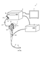
図1は、一実施の形態に係る内視鏡システムの全体構成を模式的に示す図である。図1に示す内視鏡システム1は、患者等の被検体の体腔や管腔内、例えば尿路へ内視鏡の挿入部を挿入することによって被検体の体内を撮像し、この撮像した撮像信号に基づく表示画像を表示装置に表示する。ここで、尿路とは、尿道、膀胱、尿管および腎臓等であり、奥行き方向に延びる管状をなす。医師等の術者は、表示装置が表示する表示画像の観察を行いながら、内視鏡を経由してホルミウムYAGレーザ等の高出力赤外レーザを照射するレーザ照射装置によって被検体内の結石を破砕し、破砕した結石をバスケットカテーテル等の処置具によって摘出を行い、尿路内に医療器具を所定期間するまで留置する。ここで、医療器具とは、ステント、カテーテルおよび留置針のいずれか一つである。内視鏡システム1は、内視鏡2と、表示装置3と、制御装置4と、レーザ照射装置5と、を備える。 [Configuration of endoscope system]
FIG. 1 is a diagram schematically showing an overall configuration of an endoscope system according to an embodiment. Theendoscope system 1 shown in FIG. 1 takes an image of the inside of a subject by inserting an insertion part of the endoscope into the body cavity or lumen of the subject such as a patient, for example, into the urinary tract, and this image is taken. The display image based on the signal is displayed on the display device. Here, the urinary tract is a urethra, a bladder, a ureter, a kidney, or the like, and has a tubular shape extending in the depth direction. While observing the display image displayed by the display device, a surgeon such as a doctor can use a laser irradiation device that irradiates a high-power infrared laser such as a Yttrium YAG laser via an endoscope to remove calculus in the subject. The crushed stones are crushed, and the crushed stones are removed with a treatment tool such as a basket catheter, and the medical device is placed in the urinary tract until a predetermined period of time. Here, the medical device is any one of a stent, a catheter and an indwelling needle. The endoscope system 1 includes an endoscope 2, a display device 3, a control device 4, and a laser irradiation device 5.
図1は、一実施の形態に係る内視鏡システムの全体構成を模式的に示す図である。図1に示す内視鏡システム1は、患者等の被検体の体腔や管腔内、例えば尿路へ内視鏡の挿入部を挿入することによって被検体の体内を撮像し、この撮像した撮像信号に基づく表示画像を表示装置に表示する。ここで、尿路とは、尿道、膀胱、尿管および腎臓等であり、奥行き方向に延びる管状をなす。医師等の術者は、表示装置が表示する表示画像の観察を行いながら、内視鏡を経由してホルミウムYAGレーザ等の高出力赤外レーザを照射するレーザ照射装置によって被検体内の結石を破砕し、破砕した結石をバスケットカテーテル等の処置具によって摘出を行い、尿路内に医療器具を所定期間するまで留置する。ここで、医療器具とは、ステント、カテーテルおよび留置針のいずれか一つである。内視鏡システム1は、内視鏡2と、表示装置3と、制御装置4と、レーザ照射装置5と、を備える。 [Configuration of endoscope system]
FIG. 1 is a diagram schematically showing an overall configuration of an endoscope system according to an embodiment. The
〔内視鏡の構成〕
まず、内視鏡2の構成について説明する。
内視鏡2は、被検体の体内を撮像した撮像信号(RAWデータ)を生成し、この生成した撮像信号を制御装置4へ出力する。内視鏡2は、挿入部21と、操作部22と、ユニバーサルコード23と、を備える。 [Construction of endoscope]
First, the configuration of theendoscope 2 will be described.
Theendoscope 2 generates an image pickup signal (RAW data) that images the inside of the subject, and outputs the generated image pickup signal to the control device 4. The endoscope 2 includes an insertion unit 21, an operation unit 22, and a universal cord 23.
まず、内視鏡2の構成について説明する。
内視鏡2は、被検体の体内を撮像した撮像信号(RAWデータ)を生成し、この生成した撮像信号を制御装置4へ出力する。内視鏡2は、挿入部21と、操作部22と、ユニバーサルコード23と、を備える。 [Construction of endoscope]
First, the configuration of the
The
挿入部21は、被検体内に挿入される。挿入部21は、可撓性を有する細長形状をなす。挿入部21は、後述する撮像素子を内蔵した先端部24と、複数の湾曲駒によって構成された湾曲自在な湾曲部25と、湾曲部25の基端側に接続され、可撓性を有する長尺状の可撓管部26と、を有する。
The insertion portion 21 is inserted into the subject. The insertion portion 21 has an elongated shape having flexibility. The insertion portion 21 is connected to a tip portion 24 having a built-in image pickup element, which will be described later, a bendable bending portion 25 composed of a plurality of bending pieces, and a base end side of the bending portion 25, and has a flexible length. It has a scale-shaped flexible tube portion 26 and.
先端部24は、グラスファイバ等を用いて構成される。先端部24は、ユニバーサルコード23および操作部22を経由して制御装置4から供給された照明光の導光路をなし、かつ、照明光の戻り光を撮像した撮像信号を生成して制御装置4へ出力する。
The tip portion 24 is configured by using glass fiber or the like. The tip portion 24 serves as a light guide path for the illumination light supplied from the control device 4 via the universal cord 23 and the operation unit 22, and generates an image pickup signal that captures the return light of the illumination light to control the control device 4. Output to.
操作部22は、湾曲部25を上下方向および左右方向に湾曲させる湾曲ノブ221と、体処置具を挿入する処置具挿入部222と、制御装置4に加えて、送気手段、送水手段、送ガス手段等の周辺機器の操作指示信号や内視鏡システム1に静止画撮影を指示するプリフリーズ信号または内視鏡システム1の観察モードを切り替える切替信号を入力する操作入力部である複数のスイッチ223と、を有する。処置具挿入部222から挿入される処置具は、先端部24の処置具チャンネル(図示せず)を経由して開口部(図示せず)から表出する。ここで、処置具としては、レーザ照射装置5およびバスケットカテーテル等である。
The operation unit 22 includes a bending knob 221 that bends the curved portion 25 in the vertical and horizontal directions, a treatment tool insertion section 222 for inserting a body treatment tool, and a control device 4, as well as an air supply means, a water supply means, and a power supply. Multiple switches that are operation input units that input operation instruction signals for peripheral devices such as gas means, prefreeze signals for instructing the endoscope system 1 to shoot still images, or switching signals for switching the observation mode of the endoscope system 1. 223 and. The treatment tool inserted from the treatment tool insertion portion 222 is exposed from the opening (not shown) via the treatment tool channel (not shown) of the tip portion 24. Here, the treatment tool includes a laser irradiation device 5, a basket catheter, and the like.
ユニバーサルコード23は、ライトガイドと、1または複数のケーブルをまとめた集光ケーブルと、を少なくとも内蔵している。集合ケーブルは、内視鏡2および制御装置4の間で信号を送受信する信号線であって、撮像信号(RAWデータ)を送受信するための信号線および後述する撮像素子を駆動するための駆動用のタイミング信号(同期信号およびクロック信号)を送受信するための信号線老を含む。ユニバーサルコード23は、制御装置4に着脱自在なコネクタ部27と、コイル状のコイルケーブル27aが延設し、コイルケーブル27aの延出端に制御装置4に着脱自在なコネクタ部28と、を有する。
The universal cord 23 has at least a built-in light guide and a condensing cable that bundles one or more cables. The collective cable is a signal line for transmitting and receiving signals between the endoscope 2 and the control device 4, and is for driving a signal line for transmitting and receiving an image pickup signal (RAW data) and an image pickup element described later. Includes signal lines for transmitting and receiving timing signals (synchronization signals and clock signals). The universal cord 23 has a connector portion 27 detachable from the control device 4, a coil-shaped coil cable 27a extending, and a connector portion 28 detachable from the control device 4 at the extending end of the coil cable 27a. ..
〔表示装置の構成〕
次に、表示装置3の構成について説明する。
表示装置3は、制御装置4の制御のもと、制御装置4から入力された映像信号に基づく表示画像を表示する。表示装置3は、有機EL(Electro Luminescence)や液晶等の表示パネルを用いて実現される。 [Display device configuration]
Next, the configuration of thedisplay device 3 will be described.
Thedisplay device 3 displays a display image based on the video signal input from the control device 4 under the control of the control device 4. The display device 3 is realized by using a display panel such as an organic EL (Electro Luminescence) or a liquid crystal display.
次に、表示装置3の構成について説明する。
表示装置3は、制御装置4の制御のもと、制御装置4から入力された映像信号に基づく表示画像を表示する。表示装置3は、有機EL(Electro Luminescence)や液晶等の表示パネルを用いて実現される。 [Display device configuration]
Next, the configuration of the
The
〔制御装置の構成〕
次に、制御装置4の構成について説明する。
制御装置4は、内視鏡システム1の各部を制御する。制御装置4は、内視鏡2が被検体に照射するための照明光を供給する。また、制御装置4は、内視鏡2から入力された撮像信号に対して、各種の画像処理を行って表示装置3へ出力する。 [Control device configuration]
Next, the configuration of thecontrol device 4 will be described.
Thecontrol device 4 controls each part of the endoscope system 1. The control device 4 supplies illumination light for the endoscope 2 to irradiate the subject. Further, the control device 4 performs various image processing on the image pickup signal input from the endoscope 2 and outputs the image processing to the display device 3.
次に、制御装置4の構成について説明する。
制御装置4は、内視鏡システム1の各部を制御する。制御装置4は、内視鏡2が被検体に照射するための照明光を供給する。また、制御装置4は、内視鏡2から入力された撮像信号に対して、各種の画像処理を行って表示装置3へ出力する。 [Control device configuration]
Next, the configuration of the
The
〔レーザ照射装置の構成〕
次に、レーザ照射装置の構成について説明する。
レーザ照射装置5は、内視鏡2の処置具挿入部222を経由して被検体の体内、例えば尿路(例えば腎臓、尿管、膀胱および尿道)に挿入され、術者の操作のもと、被検体内に発生した結石に向けてホルミウムYAGレーザ等の高出力赤外レーザを照射することによって結石を破砕する。 [Construction of laser irradiation device]
Next, the configuration of the laser irradiation device will be described.
Thelaser irradiation device 5 is inserted into the body of the subject, for example, the urinary tract (for example, kidney, ureter, bladder and urethra) via the treatment tool insertion portion 222 of the endoscope 2, and is operated by the operator. The stones are crushed by irradiating the stones generated in the subject with a high-power infrared laser such as a formium YAG laser.
次に、レーザ照射装置の構成について説明する。
レーザ照射装置5は、内視鏡2の処置具挿入部222を経由して被検体の体内、例えば尿路(例えば腎臓、尿管、膀胱および尿道)に挿入され、術者の操作のもと、被検体内に発生した結石に向けてホルミウムYAGレーザ等の高出力赤外レーザを照射することによって結石を破砕する。 [Construction of laser irradiation device]
Next, the configuration of the laser irradiation device will be described.
The
〔内視鏡システムの要部の機能構成〕
次に、上述した内視鏡システム1の要部の機能構成について説明する。図2は、内視鏡システム1の要部の機能構成を示すブロック図である。 [Functional configuration of key parts of the endoscope system]
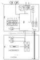
Next, the functional configuration of the main part of theendoscope system 1 described above will be described. FIG. 2 is a block diagram showing a functional configuration of a main part of the endoscope system 1.
次に、上述した内視鏡システム1の要部の機能構成について説明する。図2は、内視鏡システム1の要部の機能構成を示すブロック図である。 [Functional configuration of key parts of the endoscope system]
Next, the functional configuration of the main part of the
〔内視鏡の構成〕
まず、内視鏡2の構成について説明する。
内視鏡2は、照明光学系201と、撮像光学系202と、カットフィルタ203と、撮像素子204と、A/D変換部205と、P/S変換部206と、撮像記録部207と、撮像制御部208と、を備える。なお、照明光学系201、撮像光学系202、カットフィルタ203、撮像素子204、A/D変換部205、P/S変換部206、撮像記録部207および撮像制御部208の各々は、先端部24内に配置されてなる。 [Construction of endoscope]
First, the configuration of theendoscope 2 will be described.
Theendoscope 2 includes an illumination optical system 201, an image pickup optical system 202, a cut filter 203, an image pickup element 204, an A / D conversion unit 205, a P / S conversion unit 206, an image pickup recording unit 207, and the like. An image pickup control unit 208 is provided. The illumination optical system 201, the image pickup optical system 202, the cut filter 203, the image sensor 204, the A / D conversion unit 205, the P / S conversion unit 206, the image pickup recording unit 207, and the image pickup control unit 208 each have a tip portion 24. It is placed inside.
まず、内視鏡2の構成について説明する。
内視鏡2は、照明光学系201と、撮像光学系202と、カットフィルタ203と、撮像素子204と、A/D変換部205と、P/S変換部206と、撮像記録部207と、撮像制御部208と、を備える。なお、照明光学系201、撮像光学系202、カットフィルタ203、撮像素子204、A/D変換部205、P/S変換部206、撮像記録部207および撮像制御部208の各々は、先端部24内に配置されてなる。 [Construction of endoscope]
First, the configuration of the
The
照明光学系201は、光ファイバ等によって形成されてなるライトガイド231から供給された照明光を被検体(生体組織)に向けて照射する。照明光学系201は、1または複数のレンズ等を用いて実現される。
The illumination optical system 201 irradiates the subject (living tissue) with the illumination light supplied from the light guide 231 formed of an optical fiber or the like. The illumination optical system 201 is realized by using one or more lenses or the like.
撮像光学系202は、被検体から反射された反射光、被検体からの戻り光、被検体が発光した蛍光等の光を集光することによって被写体像(光線)を撮像素子204の受光面上に結像する。撮像光学系202は、1または複数のレンズ等を用いて実現される。
The image pickup optical system 202 collects a subject image (light ray) on the light receiving surface of the image pickup element 204 by condensing light such as reflected light reflected from the subject, return light from the subject, and fluorescence emitted by the subject. Image is formed on. The image pickup optical system 202 is realized by using one or more lenses or the like.
カットフィルタ203は、撮像光学系202と撮像素子204との光軸O1上に配置される。カットフィルタ203は、後述する制御装置4から供給された励起光であって、被検体からの励起光の反射光または戻り光の波長帯域の光を遮光し、励起光の波長帯域より長波長側の波長帯域の光を透過する。なお、カットフィルタ203の透過特性については、後述する。
The cut filter 203 is arranged on the optical axis O1 of the image pickup optical system 202 and the image pickup element 204. The cut filter 203 is the excitation light supplied from the control device 4 described later, and shields the light in the wavelength band of the reflected light or the return light of the excitation light from the subject, and is on the longer wavelength side than the wavelength band of the excitation light. Transmits light in the wavelength band of. The transmission characteristics of the cut filter 203 will be described later.
撮像素子204は、撮像制御部208の制御のもと、撮像光学系202によって結像された被写体像(光線)であって、カットフィルタ203を透過した被写体像(光線)を受光し、光電変換を行って撮像信号(RAWデータ)を生成してA/D変換部205へ出力する。撮像素子204は、2次元マトリクス状に配置されてなる複数の画素の各々に、ベイヤー配列(RGGB)を構成するカラーフィルタのいずれか1つが配置されてなるCCD(Charge Coupled Device)またはCMOS(Complementary Metal Oxide Semiconductor)のイメージセンサを用いて実現される。
The image sensor 204 receives a subject image (light ray) formed by the image pickup optical system 202 under the control of the image pickup control unit 208 and has passed through the cut filter 203, and performs photoelectric conversion. To generate an image pickup signal (RAW data) and output it to the A / D conversion unit 205. The image pickup device 204 is a CCD (Charge Coupled Device) or CMOS (Complementary) in which any one of the color filters constituting the Bayer array (RGGB) is arranged in each of a plurality of pixels arranged in a two-dimensional matrix. It is realized by using the image sensor of Metal Oxide Semiconductor.
A/D変換部205は、撮像制御部208による制御のもと、撮像素子204から入力されたアナログの撮像信号に対してA/D変換処理を行ってP/S変換部206へ出力する。A/D変換部205は、A/D変換回路等を用いて実現される。
Under the control of the image pickup control unit 208, the A / D conversion unit 205 performs A / D conversion processing on the analog image pickup signal input from the image pickup element 204 and outputs the analog image pickup signal to the P / S conversion unit 206. The A / D conversion unit 205 is realized by using an A / D conversion circuit or the like.
P/S変換部206は、撮像制御部208による制御のもと、A/D変換部205から入力されたデジタルの撮像信号をパラレル/シリアル変換を行い、このパラレル/シリアル変換を行った撮像信号を、第1の伝送ケーブル232を経由して制御装置4へ出力する。P/S変換部206は、P/S変換回路等を用いて実現される。なお、実施の形態1では、P/S変換部206に換えて、撮像信号を光信号に変換するE/O変換部を設け、光信号によって制御装置4へ撮像信号を出力するようにしてもよいし、例えばWi-Fi(Wireless Fidelity)(登録商標)等の無線通信によって撮像信号を制御装置4へ送信するようにしてもよい。
Under the control of the image pickup control unit 208, the P / S conversion unit 206 performs parallel / serial conversion on the digital image pickup signal input from the A / D conversion unit 205, and performs the parallel / serial conversion on the image pickup signal. Is output to the control device 4 via the first transmission cable 232. The P / S conversion unit 206 is realized by using a P / S conversion circuit or the like. In the first embodiment, instead of the P / S conversion unit 206, an E / O conversion unit that converts the image pickup signal into an optical signal is provided, and the image pickup signal is output to the control device 4 by the optical signal. Alternatively, the image pickup signal may be transmitted to the control device 4 by wireless communication such as Wi-Fi (Wireless Fidelity) (registered trademark).
撮像記録部207は、内視鏡2に関する各種情報(例えば撮像素子204の画素情報、カットフィルタ203の特性)を記録する。また、撮像記録部207は、第2の伝送ケーブル233を経由して制御装置4から伝送されてくる各種設定データおよび制御用のパラメータを記録する。撮像記録部207は、不揮発性メモリや揮発性メモリを用いて構成される。
The image pickup recording unit 207 records various information regarding the endoscope 2 (for example, pixel information of the image pickup element 204, characteristics of the cut filter 203). Further, the image pickup recording unit 207 records various setting data and control parameters transmitted from the control device 4 via the second transmission cable 233. The image pickup recording unit 207 is configured by using a non-volatile memory or a volatile memory.
撮像制御部208は、第2の伝送ケーブル233を経由して制御装置4から受信した設定データに基づいて、撮像素子204、A/D変換部205およびP/S変換部206の各々の動作を制御する。撮像制御部208は、TG(Timing Generator)と、CPU等のハードウェアを有する処理装置であるプロセッサと、プロセッサが使用する一時的な記憶域であるメモリを用いて実現される。
The image pickup control unit 208 operates each of the image pickup element 204, the A / D conversion unit 205, and the P / S conversion unit 206 based on the setting data received from the control device 4 via the second transmission cable 233. Control. The image pickup control unit 208 is realized by using a TG (Timing Generator), a processor which is a processing device having hardware such as a CPU, and a memory which is a temporary storage area used by the processor.
〔制御装置の構成〕
次に、制御装置4の構成について説明する。
制御装置4は、集光レンズ401と、第1の光源部402と、第2の光源部403と、光源制御部404と、S/P変換部405と、画像処理部406と、入力部407と、記録部408と、制御部409と、を備える。 [Control device configuration]
Next, the configuration of thecontrol device 4 will be described.
Thecontrol device 4 includes a condenser lens 401, a first light source unit 402, a second light source unit 403, a light source control unit 404, an S / P conversion unit 405, an image processing unit 406, and an input unit 407. And a recording unit 408 and a control unit 409.
次に、制御装置4の構成について説明する。
制御装置4は、集光レンズ401と、第1の光源部402と、第2の光源部403と、光源制御部404と、S/P変換部405と、画像処理部406と、入力部407と、記録部408と、制御部409と、を備える。 [Control device configuration]
Next, the configuration of the
The
集光レンズ401は、第1の光源部402および第2の光源部403の各々が発光した光を集光してライトガイド231へ出射する。集光レンズ401は、1または複数のレンズを用いて構成される。
The condenser lens 401 collects the light emitted by each of the first light source unit 402 and the second light source unit 403 and emits it to the light guide 231. The condenser lens 401 is configured using one or more lenses.
第1の光源部402は、光源制御部404による制御のもと、可視光である白色光(通常光)を発光することによってライトガイド231へ白色光を供給する。第1の光源部402は、コリメートレンズ、白色LED(Light Emitting Diode)ランプおよび駆動ドライバ等を用いて構成される。なお、第1の光源部402は、赤色LEDランプ、緑色LEDランプおよび青色LEDランプを用いて同時に発光することによって可視光の白色光を供給してもよい。もちろん、第1の光源部402は、ハロゲンランプやキセノンランプ等を用いて構成されてもよい。
The first light source unit 402 supplies white light to the light guide 231 by emitting white light (normal light) which is visible light under the control of the light source control unit 404. The first light source unit 402 is configured by using a collimating lens, a white LED (Light Emitting Diode) lamp, a drive driver, and the like. The first light source unit 402 may supply visible white light by simultaneously emitting light using a red LED lamp, a green LED lamp, and a blue LED lamp. Of course, the first light source unit 402 may be configured by using a halogen lamp, a xenon lamp, or the like.
第2の光源部403は、光源制御部404による制御のもと、所定の波長帯域を有する励起光を発光することによってライトガイド231へ狭帯域光を照明光として供給する。ここで、励起光は、波長帯域が400nm~430nm(中心波長が415nm)である。第2の光源部403は、コリメートレンズ、紫色LD(laser Diode)等の半導体レーザおよび駆動ドライバ等を用いて実現される。なお、第1の光源部402が発光する白色光および第2の光源部403が発光する励起光の各々の波長特性については、後述する。
Under the control of the light source control unit 404, the second light source unit 403 emits excitation light having a predetermined wavelength band to supply narrow band light to the light guide 231 as illumination light. Here, the excitation light has a wavelength band of 400 nm to 430 nm (center wavelength is 415 nm). The second light source unit 403 is realized by using a collimating lens, a semiconductor laser such as a purple LD (laser Diode), a drive driver, or the like. The wavelength characteristics of the white light emitted by the first light source unit 402 and the excitation light emitted by the second light source unit 403 will be described later.
光源制御部404は、FPGA(Field-Programmable Gate Array)またはCPU(Central Processing Unit)等のハードウェアを有する処理装置であるプロセッサと、プロセッサが使用する一時的な記憶域であるメモリと、を用いて構成される。光源制御部404は、制御部409から入力される制御データに基づいて、第1の光源部402および第2の光源部403の各々の発光タイミング、発光強度および発光時間等を制御する。
The light source control unit 404 uses a processor, which is a processing device having hardware such as an FPGA (Field-Programmable Gate Array) or a CPU (Central Processing Unit), and a memory, which is a temporary storage area used by the processor. It is composed of. The light source control unit 404 controls the light emission timing, light emission intensity, light emission time, etc. of each of the first light source unit 402 and the second light source unit 403 based on the control data input from the control unit 409.
S/P変換部405は、制御部409による制御のもと、第1の伝送ケーブル232を経由して内視鏡2から受信した撮像信号に対してシリアル/パラレル変換を行って画像処理部406へ出力する。なお、内視鏡2が光信号で撮像信号を出力する場合、S/P変換部405に換えて、光信号を電気信号に変換するO/E変換部を設けてもよい。また、内視鏡2が無線通信によって撮像信号を送信する場合、S/P変換部405に換えて、無線信号を受信可能な通信モジュールを設けてもよい。
Under the control of the control unit 409, the S / P conversion unit 405 performs serial / parallel conversion on the image pickup signal received from the endoscope 2 via the first transmission cable 232, and performs serial / parallel conversion to the image processing unit 406. Output to. When the endoscope 2 outputs an image pickup signal as an optical signal, an O / E conversion unit that converts the optical signal into an electric signal may be provided instead of the S / P conversion unit 405. Further, when the endoscope 2 transmits an imaging signal by wireless communication, a communication module capable of receiving the wireless signal may be provided instead of the S / P conversion unit 405.
画像処理部406は、CPU、GPU(Graphics Processing Unit)またはFPGA等のハードウェアを有するプロセッサと、プロセッサが使用する一時的な記憶域であるメモリと、を用いて実現される。画像処理部406は、制御部409による制御のもと、S/P変換部405から入力された撮像信号に所定の画像処理を施して表示装置3へ出力する。なお、一実施の形態では、画像処理部406が支援装置として機能する。画像処理部406は、生成部406aと、算出部406cと、抽出部406bと、推定部406dと、出力部406eと、を有する。
The image processing unit 406 is realized by using a processor having hardware such as a CPU, GPU (Graphics Processing Unit) or FPGA, and a memory which is a temporary storage area used by the processor. Under the control of the control unit 409, the image processing unit 406 performs predetermined image processing on the image pickup signal input from the S / P conversion unit 405 and outputs it to the display device 3. In one embodiment, the image processing unit 406 functions as a support device. The image processing unit 406 includes a generation unit 406a, a calculation unit 406c, an extraction unit 406b, an estimation unit 406d, and an output unit 406e.
生成部406aは、生体組織に照射した励起光によって発生した蛍光を撮像することによって生成された撮像信号に基づいて、蛍光画像を生成する。具体的には、生成部406aは、内視鏡2の撮像素子204から撮像信号を、A/D変換部205、P/S変換部206、第1の伝送ケーブル232およびS/P変換部405を経由して取得し(以下、単に「内視鏡2の撮像素子204から取得する」と記載する)する。そして、生成部406aは、内視鏡2の撮像素子204から取得した撮像信号であって、生体組織に照射した励起光によって発生した蛍光を撮像することによって生成された撮像信号に基づいて、蛍光画像を生成する。また、生成部406aは、生体組織に白色光が照射されることによって生体組織から反射した反射光および戻り光を撮像することによって生成された撮像信号に基づいて、表示画像である観察画像(白色光画像)を生成する。
The generation unit 406a generates a fluorescence image based on an imaging signal generated by imaging the fluorescence generated by the excitation light irradiating the living tissue. Specifically, the generation unit 406a inputs an image pickup signal from the image pickup element 204 of the endoscope 2, an A / D conversion unit 205, a P / S conversion unit 206, a first transmission cable 232, and an S / P conversion unit 405. (Hereinafter, it is simply described as "acquired from the image pickup element 204 of the endoscope 2"). Then, the generation unit 406a is an image pickup signal acquired from the image pickup element 204 of the endoscope 2, and fluorescence is based on the image pickup signal generated by imaging the fluorescence generated by the excitation light applied to the living tissue. Generate an image. Further, the generation unit 406a is an observation image (white) which is a display image based on an image pickup signal generated by imaging the reflected light and the return light reflected from the living body tissue by irradiating the living body tissue with white light. Optical image) is generated.
抽出部406bは、蛍光画像から蛍光領域を抽出する。具体的には、抽出部406bは、蛍光画像の各画素に対して2値化処理を行うことによって蛍光領域を抽出する。例えば、抽出部406bは、蛍光画像の各画素の画素値に対して、所定の値以上の画素を抽出することによって蛍光領域を抽出する。
Extraction unit 406b extracts the fluorescence region from the fluorescence image. Specifically, the extraction unit 406b extracts the fluorescence region by performing a binarization process on each pixel of the fluorescence image. For example, the extraction unit 406b extracts a fluorescence region by extracting pixels having a predetermined value or more with respect to the pixel value of each pixel of the fluorescence image.
算出部406cは、生成部406aが生成した蛍光画像に基づいて、蛍光強度を算出する。具体的には、算出部406cは、生成部406aが生成した蛍光画像であって、抽出部406bによって抽出された蛍光領域の蛍光強度を算出する。
The calculation unit 406c calculates the fluorescence intensity based on the fluorescence image generated by the generation unit 406a. Specifically, the calculation unit 406c calculates the fluorescence intensity of the fluorescent region of the fluorescent image generated by the generation unit 406a and extracted by the extraction unit 406b.
推定部406dは、算出部406cが算出した蛍光強度に基づいて、管腔内に留置する医療器具の留置期間を推定する。ここで、管腔とは、尿路である。また、尿路は、尿道、膀胱、尿管および腎臓を含む。また、医療器具とは、ステント、カテーテルおよび留置針のいずれか一つである。また、推定部406dは、算出部406cが算出した蛍光強度に基づいて、生体組織に対するエネルギーデバイスによる侵襲度を推定し、この侵襲度に基づいて、医療器具の留置期間を推定する。具体的には、推定部406dは、後述する相関情報記録部408bが記録する侵襲度と蛍光強度との相関関係を示す相関情報と、算出部406cが算出した蛍光強度と、に基づいて、生体組織に対するエネルギーデバイスによる侵襲度を推定する。
The estimation unit 406d estimates the indwelling period of the medical device to be indwelled in the lumen based on the fluorescence intensity calculated by the calculation unit 406c. Here, the lumen is the urinary tract. The urinary tract also includes the urethra, bladder, ureter and kidneys. The medical device is any one of a stent, a catheter and an indwelling needle. Further, the estimation unit 406d estimates the degree of invasion of the living tissue by the energy device based on the fluorescence intensity calculated by the calculation unit 406c, and estimates the indwelling period of the medical device based on this degree of invasion. Specifically, the estimation unit 406d is based on the correlation information recording the correlation between the invasiveness and the fluorescence intensity recorded by the correlation information recording unit 408b, which will be described later, and the fluorescence intensity calculated by the calculation unit 406c. Estimate the degree of invasion of the tissue by the energy device.
出力部406eは、推定部406dによって推定された医療器具の留置期間に関する留置期間情報と、生体組織を撮像した表示画像としての観察画像と、を表示装置3へ出力する。
The output unit 406e outputs the indwelling period information regarding the indwelling period of the medical device estimated by the estimation unit 406d and the observation image as a display image of the living tissue to the display device 3.
入力部407は、内視鏡システム1に関する各種操作の入力を受け付け、受け付けた操作を制御部409へ出力する。入力部407は、マウス、フットスイッチ、キーボード、ボタン、スイッチおよびタッチパネル等を用いて構成される。
The input unit 407 receives inputs for various operations related to the endoscope system 1 and outputs the accepted operations to the control unit 409. The input unit 407 is configured by using a mouse, a foot switch, a keyboard, a button, a switch, a touch panel, and the like.
記録部408は、揮発性メモリ、不揮発性メモリ、SSD(Solid State Drive)およびHDD(Hard Disk Drive)等やメモリカード等の記録媒体を用いて実現される。記録部408は、内視鏡システム1の動作に必要な各種パラメータ等を含むデータを記録する。また、記録部408は、内視鏡システム1を動作させるための各種プログラムを記録するプログラム記録部408aと、相関情報記録部408bと、を有する。
The recording unit 408 is realized by using a recording medium such as a volatile memory, a non-volatile memory, an SSD (Solid State Drive), an HDD (Hard Disk Drive), or a memory card. The recording unit 408 records data including various parameters necessary for the operation of the endoscope system 1. Further, the recording unit 408 includes a program recording unit 408a for recording various programs for operating the endoscope system 1 and a correlation information recording unit 408b.
相関情報記録部408bは、被検体の生体組織に対するレーザ照射装置5による侵襲度と、レーザ照射装置5によって熱処理された生体組織に対して励起光を照射した際に発光する蛍光強度と、の相関関係を示す相関情報を記録する。なお、相関情報の詳細は、後述する。
The correlation information recording unit 408b correlates between the degree of invasiveness of the biological tissue of the subject by the laser irradiation device 5 and the fluorescence intensity emitted when the biological tissue heat-treated by the laser irradiation device 5 is irradiated with excitation light. Record the correlation information that indicates the relationship. The details of the correlation information will be described later.
制御部409は、FPGAまたはCPU等のハードウェアを有するプロセッサと、プロセッサが使用する一時的な記憶域であるメモリと、を用いて実現される。制御部409は、内視鏡システム1を構成する各部を統括的に制御する。
The control unit 409 is realized by using a processor having hardware such as FPGA or CPU and a memory which is a temporary storage area used by the processor. The control unit 409 comprehensively controls each unit constituting the endoscope system 1.
〔励起光の波長特性〕
次に、第2の光源部403が発光する励起光の波長特性について説明する。
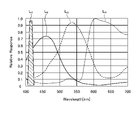
図3は、第2の光源部403が発光する励起光の波長特性を模式的に示す図である。図3において、横軸が波長(nm)を示し、縦軸が波長特性を示す。また、図3において、折れ線LVが第2の光源部403が発光する励起光の波長特性を示す。また、図3において、曲線LBが青色の波長帯域を示し、曲線LGが緑色の波長帯域を示し、曲線LRが赤色の波長帯域を示す。 [Wavelength characteristics of excitation light]
Next, the wavelength characteristics of the excitation light emitted by the secondlight source unit 403 will be described.
FIG. 3 is a diagram schematically showing the wavelength characteristics of the excitation light emitted by the secondlight source unit 403. In FIG. 3, the horizontal axis indicates the wavelength (nm), and the vertical axis indicates the wavelength characteristic. Further, in FIG. 3, the polygonal line LV shows the wavelength characteristic of the excitation light emitted by the second light source unit 403. Further, in FIG. 3, the curve LB indicates a blue wavelength band, the curve LG indicates a green wavelength band, and the curve LR indicates a red wavelength band.
次に、第2の光源部403が発光する励起光の波長特性について説明する。
図3は、第2の光源部403が発光する励起光の波長特性を模式的に示す図である。図3において、横軸が波長(nm)を示し、縦軸が波長特性を示す。また、図3において、折れ線LVが第2の光源部403が発光する励起光の波長特性を示す。また、図3において、曲線LBが青色の波長帯域を示し、曲線LGが緑色の波長帯域を示し、曲線LRが赤色の波長帯域を示す。 [Wavelength characteristics of excitation light]
Next, the wavelength characteristics of the excitation light emitted by the second
FIG. 3 is a diagram schematically showing the wavelength characteristics of the excitation light emitted by the second
図3に示すように、第2の光源部403は、中心波長(ピーク波長)が415nmであり、波長帯域が400nm~430nmである励起光を発光する。
As shown in FIG. 3, the second light source unit 403 emits excitation light having a center wavelength (peak wavelength) of 415 nm and a wavelength band of 400 nm to 430 nm.
〔カットフィルタの透過特性〕
次に、カットフィルタ203の透過特性について説明する。
図4は、カットフィルタ203の透過特性を模式的に示す図である。図4において、横軸が波長(nm)を示す、縦軸が透過特性を示す。また、図4において、折れ線LFがカットフィルタ203の透過特性を示し、折れ線LVが励起光の波長特性を示し、折れ線LNGが、生体組織に対するエネルギーデバイス、例えばレーザ照射装置5による熱処理によって生じる終末糖化産物に対して励起光を照射することによって生じる蛍光の波長特性を示す。 [Transparency characteristics of cut filter]
Next, the transmission characteristics of thecut filter 203 will be described.
FIG. 4 is a diagram schematically showing the transmission characteristics of thecut filter 203. In FIG. 4, the horizontal axis indicates the wavelength (nm), and the vertical axis indicates the transmission characteristic. Further, in FIG. 4, the broken line LF shows the transmission characteristic of the cut filter 203, the broken line LV shows the wavelength characteristic of the excitation light, and the broken line NG shows the heat treatment of the living tissue by an energy device, for example, a laser irradiation device 5. The wavelength characteristics of fluorescence generated by irradiating the resulting terminal saccharification product with excitation light are shown.
次に、カットフィルタ203の透過特性について説明する。
図4は、カットフィルタ203の透過特性を模式的に示す図である。図4において、横軸が波長(nm)を示す、縦軸が透過特性を示す。また、図4において、折れ線LFがカットフィルタ203の透過特性を示し、折れ線LVが励起光の波長特性を示し、折れ線LNGが、生体組織に対するエネルギーデバイス、例えばレーザ照射装置5による熱処理によって生じる終末糖化産物に対して励起光を照射することによって生じる蛍光の波長特性を示す。 [Transparency characteristics of cut filter]
Next, the transmission characteristics of the
FIG. 4 is a diagram schematically showing the transmission characteristics of the
図4の折れ線LVおよび折れ線LNGに示すように、カットフィルタ203は、観察領域の生体組織から反射された励起光の一部を遮光し、蛍光成分を含む他の波長帯域の光を透過する。具体的には、カットフィルタ203は、励起光を含む400nm~430nm未満の短波長側の波長帯域の光の一部を遮光し、かつ、熱処理によって生じる終末糖化産物に対して励起光を照射することによって生じる蛍光を含む430nmより長波長側の波長帯域の光を透過する。
As shown in the broken line LV and the broken line NG in FIG. 4, the cut filter 203 shields a part of the excitation light reflected from the living tissue in the observation region and transmits light in other wavelength bands including a fluorescent component. do. Specifically, the cut filter 203 shields a part of the light in the wavelength band on the short wavelength side of 400 nm to less than 430 nm including the excitation light, and irradiates the terminal saccharified product produced by the heat treatment with the excitation light. It transmits light in a wavelength band longer than 430 nm, including fluorescence generated by this.
〔相関情報〕
次に、相関情報記録部408bが記録する相関情報の一例について説明する。
図5は、相関情報記録部408bが記録する相関情報の一例を示す図である。図5において、縦軸が発光強度を示し、横軸が熱処理による生体組織への侵襲度(深度および領域)を示す。また、図5において、直線Lyは、発光強度と熱処置による生体組織への侵襲度(深度および領域)との相関関係を示す。 [Correlation information]
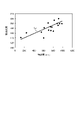
Next, an example of the correlation information recorded by the correlationinformation recording unit 408b will be described.
FIG. 5 is a diagram showing an example of correlation information recorded by the correlationinformation recording unit 408b. In FIG. 5, the vertical axis shows the emission intensity, and the horizontal axis shows the degree of invasion (depth and region) into the living tissue by the heat treatment. Further, in FIG. 5, the straight line Ly indicates the correlation between the luminescence intensity and the degree of invasion (depth and region) of the living tissue by the heat treatment.
次に、相関情報記録部408bが記録する相関情報の一例について説明する。
図5は、相関情報記録部408bが記録する相関情報の一例を示す図である。図5において、縦軸が発光強度を示し、横軸が熱処理による生体組織への侵襲度(深度および領域)を示す。また、図5において、直線Lyは、発光強度と熱処置による生体組織への侵襲度(深度および領域)との相関関係を示す。 [Correlation information]
Next, an example of the correlation information recorded by the correlation
FIG. 5 is a diagram showing an example of correlation information recorded by the correlation
図5の直線Lyに示すように、発光強度は、熱処理による生体組織への侵襲度が大きいほど強くなる。
As shown by the straight line Ly in FIG. 5, the luminescence intensity becomes stronger as the degree of invasion to the living tissue by the heat treatment is larger.
〔蛍光観察モードの概要〕
次に、内視鏡システム1において実行可能な蛍光観察モード(熱処置観察モード)について説明する。図6は、蛍光観察モード時における観察原理を模式的に示す図である。 [Overview of fluorescence observation mode]
Next, a fluorescence observation mode (heat treatment observation mode) that can be executed in theendoscope system 1 will be described. FIG. 6 is a diagram schematically showing the observation principle in the fluorescence observation mode.
次に、内視鏡システム1において実行可能な蛍光観察モード(熱処置観察モード)について説明する。図6は、蛍光観察モード時における観察原理を模式的に示す図である。 [Overview of fluorescence observation mode]
Next, a fluorescence observation mode (heat treatment observation mode) that can be executed in the
図6のグラフG11に示すように、まず、制御装置4は、第2の光源部403を発光させることによって、励起光(中心波長415nm)をレーザ照射装置5により被検体に対して熱処置が施された生体組織O10(熱処置領域)に照射する。この場合、図6のグラフG12に示すように、少なくとも生体組織O10(熱処置領域)で反射された励起光の成分および戻り光を含む反射光(以下、単に「反射光W10」という)は、カットフィルタ203によって遮光され強度が低下する一方、この大部分を遮光する波長帯域より長波長側の成分の一部は強度を落とさず撮像素子204に入射する。
As shown in the graph G11 of FIG. 6, first, the control device 4 causes the second light source unit 403 to emit light, so that the excitation light (center wavelength 415 nm) is heat-treated by the laser irradiation device 5 with respect to the subject. Irradiate the applied biological tissue O10 (heat treatment area). In this case, as shown in the graph G12 of FIG. 6, the reflected light including at least the components of the excitation light reflected by the biological tissue O10 (heat treatment region) and the return light (hereinafter, simply referred to as “reflected light W10”) is While the cut filter 203 shields light from light and reduces the intensity, some of the components on the wavelength side longer than the wavelength band that shields most of the light are incident on the image sensor 204 without reducing the intensity.
より具体的には、図6のグラフG12に示すように、カットフィルタ203は、G画素に入射する反射光W10であって、励起光の波長帯域を含む短波長の波長帯域の反射光W10の大部分を遮光し、この大部分を遮光する波長帯域より長波長側の波長帯域を透過する。さらに、図6のグラフG12に示すように、カットフィルタ203は、生体組織O10(熱処置領域)におけるAGEsが自家発光した蛍光(WF10)を透過する。このため、R画素、G画素およびB画素の各々には、強度が低下した反射光W10および蛍光(WF10)が入射する。
More specifically, as shown in the graph G12 of FIG. 6, the cut filter 203 is the reflected light W10 incident on the G pixel, and is the reflected light W10 having a short wavelength band including the wavelength band of the excitation light. Most of it is shielded from light, and the wavelength band on the longer wavelength side than the wavelength band that shields most of this light is transmitted. Further, as shown in the graph G12 of FIG. 6, the cut filter 203 transmits the fluorescence (WF10) that the AGEs in the living tissue O10 (heat treatment region) self-emit. Therefore, the reflected light W10 and the fluorescence (WF10) having reduced intensities are incident on each of the R pixel, the G pixel, and the B pixel.
また、図6のグラフG12における蛍光特性の折れ線LNGに示すように、G画素は、蛍光に感度を有するが、蛍光が微小な反応のため、出力値が小さい値となる。
Further, as shown in the line L NG of the fluorescence characteristic in the graph G12 of FIG. 6, the G pixel has sensitivity to fluorescence, but the output value is small because the fluorescence is a minute reaction.
その後、画像処理部406は、内視鏡2の撮像素子204から撮像信号(RAWデータ)を取得し、取得した撮像信号に含まれるG画素およびB画素の各々の信号値に対して画像処理を行って蛍光画像を生成する。この場合において、G画素の信号値には、熱処置領域から発せられた蛍光情報が含まれる。また、B画素には、熱処置領域を含む被検体の生体組織からの背景情報が含まれる。この場合、画像処理部406は、デモザイク処理、画素毎の強度比を算出する処理、蛍光領域と背景領域とを判定する処理、蛍光領域に位置する画素の色成分信号(画素値)および背景領域に位置する画素の色成分信号(画素値)の各々に対して互いに異なるパラメータの画像処理を行って蛍光画像を生成する。そして、画像処理部406は、蛍光画像を表示装置3へ出力する。ここで、蛍光領域とは、背景情報に比べて蛍光情報が優位な領域である。また、背景領域とは、蛍光情報に比べて背景情報が優位な領域を指す。具体的には、画像処理部93における抽出部406bは、画素に含まれる背景情報に相当する反射光成分信号と蛍光情報に相当する蛍光成分信号との強度比が所定の閾値以上(例えば0.5 以上)である場合、蛍光領域と判定する一方、強度比が所定の閾値未満である場合、背景領域として判定することによって、蛍光領域と背景領域とを抽出する。
After that, the image processing unit 406 acquires an image pickup signal (RAW data) from the image pickup element 204 of the endoscope 2, and performs image processing on each signal value of the G pixel and the B pixel included in the acquired image pickup signal. To generate a fluorescent image. In this case, the signal value of the G pixel includes the fluorescence information emitted from the heat treatment region. Further, the B pixel contains background information from the biological tissue of the subject including the heat treatment region. In this case, the image processing unit 406 performs demosaic processing, processing for calculating the intensity ratio for each pixel, processing for determining between the fluorescent region and the background region, and the color component signal (pixel value) and the background region of the pixels located in the fluorescent region. Image processing of parameters different from each other is performed on each of the color component signals (pixel values) of the pixels located in to generate a fluorescent image. Then, the image processing unit 406 outputs the fluorescent image to the display device 3. Here, the fluorescence region is a region in which fluorescence information is superior to background information. Further, the background region refers to a region where the background information is superior to the fluorescence information. Specifically, in the extraction unit 406b of the image processing unit 93, the intensity ratio of the reflected light component signal corresponding to the background information and the fluorescence component signal corresponding to the fluorescence information contained in the pixel is equal to or higher than a predetermined threshold value (for example, 0. If it is 5 or more), it is determined to be a fluorescent region, while if the intensity ratio is less than a predetermined threshold value, it is determined to be a background region to extract the fluorescent region and the background region.
このように蛍光観察モード(熱処置観察モード)は、レーザ照射装置5によって熱処理された生体組織(熱処置領域)を容易に観察することができる。
As described above, in the fluorescence observation mode (heat treatment observation mode), the biological tissue (heat treatment region) heat-treated by the laser irradiation device 5 can be easily observed.
〔通常光観察モードの概要〕
次に、内視鏡システム1が実行可能な通常光観察モードについて説明する。図7は、通常光観察モード時における観察原理を模式的に示す図である。 [Overview of normal light observation mode]
Next, a normal light observation mode that can be executed by theendoscope system 1 will be described. FIG. 7 is a diagram schematically showing the observation principle in the normal light observation mode.
次に、内視鏡システム1が実行可能な通常光観察モードについて説明する。図7は、通常光観察モード時における観察原理を模式的に示す図である。 [Overview of normal light observation mode]
Next, a normal light observation mode that can be executed by the
図7に示すように、まず、制御装置4は、第1の光源部402を発光させることによって、白色光W3を被検体の生体組織O10に照射する。この場合、生体組織O10で反射された反射光および戻り光(以下、単に「反射光WR30、反射光WG30,反射光WB30」という)は、一部がカットフィルタ203に遮光され、残りが撮像素子204に入射する。具体的には、図7に示すように、カットフィルタ203は、狭帯域光の波長帯域を含む短波長の波長帯域の反射光を遮光する。このため、図7に示すように、B画素に入射する青色の波長帯域の光の成分が、カットフィルタ203を配置していない状態と比べて小さくなる。
As shown in FIG. 7, first, the control device 4 irradiates the living tissue O10 of the subject with white light W3 by causing the first light source unit 402 to emit light. In this case, a part of the reflected light and the return light reflected by the living tissue O10 (hereinafter, simply referred to as "reflected light WR30, reflected light WG30, reflected light WB30") is shielded by the cut filter 203, and the rest is an image pickup element. It is incident on 204. Specifically, as shown in FIG. 7, the cut filter 203 shields reflected light in a short wavelength wavelength band including a narrow band light wavelength band. Therefore, as shown in FIG. 7, the light component in the blue wavelength band incident on the B pixel is smaller than that in the state where the cut filter 203 is not arranged.
続いて、画像処理部406は、撮像素子204から撮像信号(RAWデータ)を取得し、取得した撮像信号に含まれるR画素、G画素およびB画素の各々の信号値に対して画像処理を行って表示画像である観察画像(白色光画像)を生成する。この場合において、画像処理部406は、撮像信号タに含まれる青色成分が従来の白色光観察と比べて小さいため、赤色成分、緑色成分および青色成分の比率が一定となるようにホワイトバランスを調整するホワイトバランス調整処理を行う。
Subsequently, the image processing unit 406 acquires an image pickup signal (RAW data) from the image pickup element 204, and performs image processing on each signal value of the R pixel, the G pixel, and the B pixel included in the acquired image pickup signal. An observation image (white light image), which is a display image, is generated. In this case, the image processing unit 406 adjusts the white balance so that the ratios of the red component, the green component, and the blue component are constant because the blue component contained in the image pickup signal is smaller than that of the conventional white light observation. Perform white balance adjustment processing.
このように通常光観察モードは、カットフィルタ203を配置している場合であっても、自然な観察画像(白色画像)を観察することができる。
As described above, in the normal light observation mode, a natural observation image (white image) can be observed even when the cut filter 203 is arranged.
〔内視鏡システムを用いた経尿道的尿路結石除去術の手技方法〕
次に、術者が内視鏡システム1を用いた経尿道的尿路結石除去術(f-TUL)の手技方法について説明する。図8は、術者が内視鏡システム1を用いた経尿道的尿路結石除去術(f-TUL)の手技方法を説明するフローチャートである。図9A~図9Fは、経尿道的尿路結石除去術(f-TUL)において表示装置3が表示する画像遷移の一例を示す図である。 [Procedure method for transurethral urethral stone removal using an endoscopic system]
Next, the surgeon will explain a procedure for transurethral urethral stone removal (f-TUL) using theendoscopic system 1. FIG. 8 is a flowchart illustrating a procedure method of transurethral urethral stone removal (f-TUL) by the operator using the endoscope system 1. 9A-9F are diagrams showing an example of image transitions displayed by the display device 3 in transurethral urethral stone removal (f-TUL).
次に、術者が内視鏡システム1を用いた経尿道的尿路結石除去術(f-TUL)の手技方法について説明する。図8は、術者が内視鏡システム1を用いた経尿道的尿路結石除去術(f-TUL)の手技方法を説明するフローチャートである。図9A~図9Fは、経尿道的尿路結石除去術(f-TUL)において表示装置3が表示する画像遷移の一例を示す図である。 [Procedure method for transurethral urethral stone removal using an endoscopic system]
Next, the surgeon will explain a procedure for transurethral urethral stone removal (f-TUL) using the
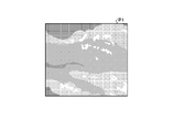
図8に示すように、まず、術者は、内視鏡2に白色光(通常光)を照射させながら被検体の尿路(尿管)に内視鏡2の挿入部21を挿入する(ステップS1)。この場合、図9Aに示すように、術者は、表示装置3で表示される白色光による観察画像P1を観察しながら内視鏡2の挿入部21を被検体の尿路内に挿入する。
As shown in FIG. 8, the surgeon first inserts the insertion portion 21 of the endoscope 2 into the urinary tract (ureter) of the subject while irradiating the endoscope 2 with white light (normal light) (as shown in FIG. 8). Step S1). In this case, as shown in FIG. 9A, the operator inserts the insertion portion 21 of the endoscope 2 into the urinary tract of the subject while observing the observation image P1 by the white light displayed on the display device 3.
続いて、術者は、表示装置3で表示される観察画像P1を見ながら被検体における発生した結石の確認を行う(ステップS2)。この場合、図9Bに示すように、術者は、表示装置3で表示される観察画像P2を観察しながら内視鏡2の挿入部21を被検体の尿路内に挿入しつつ、観察画像P2を観察しながら結石K1を探索しつつ、結石K1の大きさおよび位置を確認する。
Subsequently, the surgeon confirms the calculus generated in the subject while looking at the observation image P1 displayed on the display device 3 (step S2). In this case, as shown in FIG. 9B, the surgeon inserts the insertion portion 21 of the endoscope 2 into the urinary tract of the subject while observing the observation image P2 displayed on the display device 3, and observes the image. While searching for calculus K1 while observing P2, confirm the size and position of calculus K1.
その後、術者は、表示装置3で表示される観察画像を見つつ、内視鏡2の処置具挿入部222を経由してレーザ照射装置5を被検体の尿管内に挿入して結石に向けてレーザを照射する(ステップS3)。この場合、図9Cに示すように、術者は、表示装置3で表示される観察画像P3を観察しながら、結石K1に向けてレーザ照射装置5によってレーザを照射させることによって結石K1を破砕する。
After that, the surgeon inserts the laser irradiation device 5 into the urinary tract of the subject via the treatment tool insertion portion 222 of the endoscope 2 while looking at the observation image displayed on the display device 3, and directs the laser irradiation device toward the calculus. And irradiate the laser (step S3). In this case, as shown in FIG. 9C, the operator crushes the calculus K1 by irradiating the calculus K1 with a laser by the laser irradiation device 5 while observing the observation image P3 displayed on the display device 3. ..
続いて、術者は、表示装置3で表示される観察画像を見つつ、内視鏡2の処置具挿入部222を経由してバスケットによって破砕した結石を被検体から摘出する(ステップS4)。この場合、図9Dおよび図9Eに示すように、術者は、表示装置3で表示される観察画像P4または観察画像P5を見つつ、内視鏡2の処置具挿入部222を経由し、把持可能な処置具、例えばバスケットカテーテルK2によって破砕した結石K1を被検体から摘出する。
Subsequently, the surgeon extracts the calculus crushed by the basket via the treatment tool insertion portion 222 of the endoscope 2 from the subject while observing the observation image displayed on the display device 3 (step S4). In this case, as shown in FIGS. 9D and 9E, the operator grasps the observation image P4 or the observation image P5 displayed on the display device 3 via the treatment tool insertion portion 222 of the endoscope 2. A possible treatment tool, such as a calculus K1 crushed by a basket catheter K2, is removed from the subject.
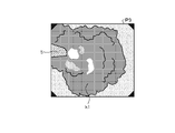
その後、術者は、内視鏡2の操作部を操作して内視鏡2が照射する観察モードを通常光観察モードから蛍光観察モード(熱処理観察モード)に切り替える(ステップS5)。この場合、制御装置4は、第2の光源部403を発光することによって、被検体に向けて励起光を照射する。このとき、図9Fに示すように、術者は、表示装置3で表示される蛍光画像P6に含まれる蛍光領域Q1を観察することによって、レーザ照射装置5による熱傷の侵襲度を把握する。
After that, the operator operates the operation unit of the endoscope 2 to switch the observation mode irradiated by the endoscope 2 from the normal light observation mode to the fluorescence observation mode (heat treatment observation mode) (step S5). In this case, the control device 4 emits the excitation light toward the subject by emitting light from the second light source unit 403. At this time, as shown in FIG. 9F, the operator grasps the degree of burn invasion by the laser irradiation device 5 by observing the fluorescence region Q1 included in the fluorescence image P6 displayed on the display device 3.
続いて、術者は、内視鏡2の操作部22を操作して内視鏡2の観察モードを蛍光観察モードと通常光観察モードとを交互に切り替えながらレーザ照射装置5による周辺組織への熱傷の侵襲度を把握する(ステップS6)。
Subsequently, the operator operates the operation unit 22 of the endoscope 2 to alternately switch the observation mode of the endoscope 2 between the fluorescence observation mode and the normal light observation mode, and the laser irradiation device 5 is used to apply the laser irradiation device to the surrounding tissue. The degree of invasion of the burn is grasped (step S6).
その後、術者は、表示装置3が表示するステントを留置するか否かの有無、および留置期間を参照しつつ、ステントの留置および留置期間を決定する(ステップS7)。この場合、制御装置4は、蛍光画像P6に含まれる発光領域の発光強度に基づいて、尿路内にステントを留置するか否かの有無、および留置期間に関する留置期間情報を表示装置3で表示する観察画像上に出力する。これにより、術者は、表示装置3で表示される留置期間情報を参考に、尿路内にステントを留置するか否かの有無、および留置期間を決定する。なお、制御装置4が表示装置3に表示させる尿路内におけるステントを留置するか否かの有無、および留置期間の推定方法については、後述する。
After that, the operator determines the indwelling and indwelling period of the stent with reference to whether or not the stent displayed by the display device 3 is indwelled and the indwelling period (step S7). In this case, the control device 4 displays on the display device 3 whether or not the stent is placed in the urinary tract and the indwelling period information regarding the indwelling period based on the emission intensity of the light emitting region included in the fluorescence image P6. Output on the observation image. Thereby, the surgeon determines whether or not to indwell the stent in the urinary tract and the indwelling period with reference to the indwelling period information displayed on the display device 3. The presence or absence of indwelling a stent in the urinary tract displayed by the control device 4 on the display device 3 and the method of estimating the indwelling period will be described later.
続いて、術者は、尿路内にステントを留置する場合、尿路内にステントを留置する(ステップS8)。その後、術者は、被検体の尿路から内視鏡2を抜き出して手技を終了する。
Subsequently, when the stent is placed in the urinary tract, the operator places the stent in the urinary tract (step S8). After that, the operator removes the endoscope 2 from the urinary tract of the subject and completes the procedure.
このように、術者は、被検体の尿路内に位置する結石をレーザによって破砕し、被検体から破砕した結石を処置具等によって摘出した後、内視鏡システム1の観察モードを通常光観察モードから蛍光観察モードに切り替えて、被検体の生体組織に対するレーザの侵襲度を把握することによってステントの留置の有無および留置期間を決定する。
In this way, the surgeon crushes the calculus located in the urinary tract of the subject with a laser, removes the crushed stone from the subject with a treatment tool or the like, and then sets the observation mode of the endoscope system 1 to normal light. By switching from the observation mode to the fluorescence observation mode and grasping the degree of laser invasion of the living tissue of the subject, the presence or absence of stent placement and the placement period are determined.
〔内視鏡システムの処理〕
次に、内視鏡システム1が実行する処理について説明する。
図10は、内視鏡システム1が実行する処理の概要を示すフローチャートである。 [Processing of endoscopic system]
Next, the process executed by theendoscope system 1 will be described.
FIG. 10 is a flowchart showing an outline of the process executed by theendoscope system 1.
次に、内視鏡システム1が実行する処理について説明する。
図10は、内視鏡システム1が実行する処理の概要を示すフローチャートである。 [Processing of endoscopic system]
Next, the process executed by the
FIG. 10 is a flowchart showing an outline of the process executed by the
図10に示すように、まず、制御部409は、光源制御部404を制御することによって第1の光源部402を発光させることによって白色光を被写体に向けて照射させる(ステップS101)。
As shown in FIG. 10, first, the control unit 409 controls the light source control unit 404 to cause the first light source unit 402 to emit light, thereby irradiating the subject with white light (step S101).
続いて、画像処理部406は、内視鏡2の撮像素子204から撮像信号を取得して表示画像である観察画像を生成して表示装置3に出力する(ステップS102)。
Subsequently, the image processing unit 406 acquires an image pickup signal from the image pickup element 204 of the endoscope 2, generates an observation image as a display image, and outputs the observation image to the display device 3 (step S102).
その後、制御部409は、入力部407または内視鏡2の操作部22から観察モードを蛍光観察モードに変更する変更信号が入力されたか否かを判断する(ステップS103)。制御部409によって入力部407または内視鏡2の操作部22から観察モードを蛍光観察モードに変更する変更信号が入力されたと判断された場合(ステップS103:Yes)、内視鏡システム1は、後述するステップS104へ移行する。これに対して、制御部409によって入力部407または内視鏡2の操作部22から観察モード蛍光観察モードに変更する変更信号が入力されていない場合(ステップS103:No)、内視鏡システム1は、後述するステップS120へ移行する。
After that, the control unit 409 determines whether or not a change signal for changing the observation mode to the fluorescence observation mode is input from the input unit 407 or the operation unit 22 of the endoscope 2 (step S103). When it is determined by the control unit 409 that a change signal for changing the observation mode to the fluorescence observation mode is input from the input unit 407 or the operation unit 22 of the endoscope 2 (step S103: Yes), the endoscope system 1 determines. The process proceeds to step S104, which will be described later. On the other hand, when the change signal for changing to the observation mode fluorescence observation mode is not input from the input unit 407 or the operation unit 22 of the endoscope 2 by the control unit 409 (step S103: No), the endoscope system 1 Goes to step S120, which will be described later.
ステップS104において、制御部409は、光源制御部404を制御することによって第2の光源部403に励起光を照射させる。
In step S104, the control unit 409 controls the light source control unit 404 to irradiate the second light source unit 403 with the excitation light.
続いて、画像処理部406は、内視鏡2の撮像素子204が生成した撮像信号に基づいて、蛍光画像を生成する(ステップS105)。
Subsequently, the image processing unit 406 generates a fluorescent image based on the image pickup signal generated by the image pickup element 204 of the endoscope 2 (step S105).
その後、抽出部406bは、生成部406aが生成した蛍光画像に含まれる蛍光領域を抽出する(ステップS106)。具体的には、抽出部406bは、蛍光画像に対して2値化処理等を行うことによって、蛍光領域を抽出する。なお、抽出部406bは、蛍光画像に複数の蛍光領域が含まれる場合、複数の蛍光領域を抽出する。
After that, the extraction unit 406b extracts the fluorescence region included in the fluorescence image generated by the generation unit 406a (step S106). Specifically, the extraction unit 406b extracts the fluorescence region by performing binarization processing or the like on the fluorescence image. When the fluorescent image contains a plurality of fluorescent regions, the extraction unit 406b extracts the plurality of fluorescent regions.
続いて、算出部406cは、抽出部406bが抽出した蛍光領域の蛍光強度を算出する(ステップS106)。この場合、算出部406cは、抽出部406bが複数の蛍光領域を抽出した場合、複数の蛍光領域の各々の蛍光強度を算出する。
Subsequently, the calculation unit 406c calculates the fluorescence intensity of the fluorescence region extracted by the extraction unit 406b (step S106). In this case, when the extraction unit 406b extracts a plurality of fluorescence regions, the calculation unit 406c calculates the fluorescence intensity of each of the plurality of fluorescence regions.
続いて、推定部406dは、蛍光領域が複数あるか否かを判定する(ステップS108)。推定部406dによって蛍光領域が複数あると判定した場合(ステップS108:Yes)、内視鏡システム1は、後述するステップS109へ移行する。これに対して、推定部406dによって蛍光領域が複数でないと判定した場合(ステップS108:No)、内視鏡システム1は、後述するステップS110へ移行する。
Subsequently, the estimation unit 406d determines whether or not there are a plurality of fluorescent regions (step S108). When the estimation unit 406d determines that there are a plurality of fluorescence regions (step S108: Yes), the endoscope system 1 proceeds to step S109 described later. On the other hand, when the estimation unit 406d determines that the number of fluorescent regions is not plural (step S108: No), the endoscope system 1 shifts to step S110 described later.
ステップS109において、推定部406dは、算出部406cが算出した複数の蛍光領域の中から最も強い発光強度と、相関情報記録部408bが記録する相関情報と、に基づいて、尿路内にステントを留置するか否かを推定する。具体的には、図11に示すように、推定部406dは、相関情報記録部408bが記録する相関情報と、算出部406cが算出した発光強度と、に基づいて、尿路内にステントを留置するか否かを推定する。例えば、図11に示すように、推定部406dは、相関情報記録部408bが記録する相関情報と、算出部406cが算出した発光強度と、に基づいて、発光強度がステントの留置不要な値を示す閾値TL1未満であるか否かを判定し、発光強度が閾値TL1未満である場合、尿路内におけるステントの留置を不要と推定する。これに対して、推定部406dは、相関情報記録部408bが記録する相関情報と、算出部406cが算出した発光強度と、に基づいて、発光強度が閾値TL1以上である場合、尿路内におけるステントの留置が必要と推定する。ステップS109の後、内視鏡システム1は、後述するステップS111へ移行する。
In step S109, the estimation unit 406d places a stent in the urinary tract based on the strongest emission intensity from the plurality of fluorescence regions calculated by the calculation unit 406c and the correlation information recorded by the correlation information recording unit 408b. Estimate whether or not to detain. Specifically, as shown in FIG. 11, the estimation unit 406d places a stent in the urinary tract based on the correlation information recorded by the correlation information recording unit 408b and the emission intensity calculated by the calculation unit 406c. Estimate whether or not to do. For example, as shown in FIG. 11, the estimation unit 406d determines the value of the emission intensity that does not require stent placement based on the correlation information recorded by the correlation information recording unit 408b and the emission intensity calculated by the calculation unit 406c. It is determined whether or not the indicated threshold value is less than TL1, and if the emission intensity is less than the threshold value TL1, it is presumed that the placement of the stent in the urinary tract is unnecessary. On the other hand, the estimation unit 406d is in the urinary tract when the emission intensity is equal to or higher than the threshold value TL1 based on the correlation information recorded by the correlation information recording unit 408b and the emission intensity calculated by the calculation unit 406c. It is presumed that stent placement is necessary. After step S109, the endoscope system 1 shifts to step S111 described later.
ステップS110において、推定部406dは、算出部406cが算出した発光強度と、相関情報記録部408bが記録する相関情報と、に基づいて、ステントを留置するか否かの有無を推定する。ステップS110の後、内視鏡システム1は、後述するステップS111へ移行する。
In step S110, the estimation unit 406d estimates whether or not to place the stent based on the emission intensity calculated by the calculation unit 406c and the correlation information recorded by the correlation information recording unit 408b. After step S110, the endoscope system 1 shifts to step S111 described later.
ステップS111において、推定部406dによって尿路内にステントを留置すると推定された場合(ステップS111:Yes)、内視鏡システム1は、後述するステップS112へ移行する。これに対して、推定部406dによって尿路内にステントを留置すると指定された場合(ステップS111:No)、内視鏡システム1は、後述するステップS114へ移行する。
In step S111, when it is estimated that the stent is placed in the urinary tract by the estimation unit 406d (step S111: Yes), the endoscope system 1 shifts to step S112 described later. On the other hand, when the estimation unit 406d specifies that the stent is to be placed in the urinary tract (step S111: No), the endoscope system 1 shifts to step S114 described later.
ステップS112において、推定部406dは、算出部406cが算出した発光強度と、相関情報記録部408bが記録する相関情報と、に基づいて、尿路内におけるステントの留置期間を推定する。具体的には、図12に示すように、推定部406dは、算出部406cが算出した発光強度と、相関情報記録部408bが記録する相関情報と、に基づいて、尿路内におけるステントの留置期間を推定する。例えば、図12に示すように、推定部406dは、算出部406cが算出した発光強度と、相関情報記録部408bが記録する相関情報と、に基づいて、発光強度と侵襲度との相関関係が第1の領域Z1に位置する場合(Low)、ステントの留置期間を短めと推定し、発光強度と侵襲度との相関関係が第2の領域Z2に位置する場合(middlee)、ステントの留置期間を通常と推定し、発光強度と侵襲度との相関関係が第3の領域Z3に位置する場合(High)、ステントの留置期間を長めと推定する。ここで、短めとは、数日程度であり、通常とは、1週間程度であり、長めとは、10日以上である。
In step S112, the estimation unit 406d estimates the indwelling period of the stent in the urinary tract based on the emission intensity calculated by the calculation unit 406c and the correlation information recorded by the correlation information recording unit 408b. Specifically, as shown in FIG. 12, the estimation unit 406d places a stent in the urinary tract based on the emission intensity calculated by the calculation unit 406c and the correlation information recorded by the correlation information recording unit 408b. Estimate the period. For example, as shown in FIG. 12, the estimation unit 406d has a correlation between the emission intensity and the degree of invasiveness based on the emission intensity calculated by the calculation unit 406c and the correlation information recorded by the correlation information recording unit 408b. When located in the first region Z1 (Low), the indwelling period of the stent is estimated to be short, and when the correlation between the luminescence intensity and the degree of invasiveness is located in the second region Z2 (middlee), the indwelling period of the stent is estimated. Is estimated to be normal, and when the correlation between the emission intensity and the degree of invasiveness is located in the third region Z3 (High), it is estimated that the indwelling period of the stent is longer. Here, the short term is about several days, the normal term is about one week, and the long term is 10 days or more.
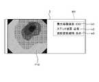
続いて、出力部406eは、表示装置3に向けて留置期間情報を出力する(ステップS113)。具体的には、図13に示すように、出力部406eは、留置期間情報M1と、表示画像である観察画像P10と、を表示装置3へ出力する。留置期間情報M1には、最大侵襲度m1(蛍光強度に基づく最大侵襲深度)、ステント留置の有無m2およびステントの推奨留置期間m3と、が含まれる。
Subsequently, the output unit 406e outputs the indwelling period information to the display device 3 (step S113). Specifically, as shown in FIG. 13, the output unit 406e outputs the indwelling period information M1 and the observation image P10 which is a display image to the display device 3. The indwelling period information M1 includes a maximum invasiveness m1 (maximum invasion depth based on fluorescence intensity), a presence / absence of stent placement m2, and a recommended placement period m3 of the stent.
その後、制御部409は、入力部407または内視鏡2の操作部22から観察モードを通常光観察モードに変更する変更信号が入力されたか否かを判断する(ステップS114)。制御部409によって入力部407または内視鏡2の操作部22から観察モードを通常光観察モードに変更する変更信号が入力されたと判断された場合(ステップS114:Yes)、内視鏡システム1は、後述するステップS115へ移行する。これに対して、制御部409によって入力部407または内視鏡2の操作部22から観察モードを通常光観察モードに変更する変更信号が入力されていないと判断された場合(ステップS114:No)、内視鏡システム1は、上述したステップS104へ戻る。
After that, the control unit 409 determines whether or not a change signal for changing the observation mode to the normal light observation mode is input from the input unit 407 or the operation unit 22 of the endoscope 2 (step S114). When it is determined by the control unit 409 that a change signal for changing the observation mode to the normal light observation mode is input from the input unit 407 or the operation unit 22 of the endoscope 2 (step S114: Yes), the endoscope system 1 , The process proceeds to step S115 described later. On the other hand, when it is determined by the control unit 409 that the change signal for changing the observation mode to the normal light observation mode has not been input from the input unit 407 or the operation unit 22 of the endoscope 2 (step S114: No). , The endoscope system 1 returns to step S104 described above.
ステップS115において、制御部409は、光源制御部404を制御することによって、第1の光源部402を発光させることによって白色光を照射させる。
In step S115, the control unit 409 controls the light source control unit 404 to cause the first light source unit 402 to emit light to irradiate white light.
続いて、画像処理部406は、内視鏡2の撮像素子204から撮像信号を取得して観察画像を生成して表示装置3に出力する(ステップS116)。具体的には、生成部406aは、撮像素子204から撮像信号を取得し、この撮像信号に基づいて、観察画像を生成する。
Subsequently, the image processing unit 406 acquires an image pickup signal from the image pickup element 204 of the endoscope 2, generates an observation image, and outputs the observation image to the display device 3 (step S116). Specifically, the generation unit 406a acquires an image pickup signal from the image pickup element 204 and generates an observation image based on the image pickup signal.
その後、制御部409は、推定部406dによって生体組織に対してレーザによる侵襲があったか否かを判断する(ステップS117)。具体的には、制御部409は、推定部406dによって尿路内にステントを留置すると推定したか否かを判断し、推定部406dが尿路内にステントを留置すると推定した場合、生体組織に対してレーザによる侵襲があったと判断する。制御部409によって生体組織に対してレーザによる侵襲があったと判断された場合(ステップS117:Yes)、内視鏡システム1は、後述するステップS118へ移行する。これに対して、制御部409によって生体組織に対してレーザによる侵襲があったと判断された場合(ステップS117:No)、内視鏡システム1は、後述するステップS119へ移行する。
After that, the control unit 409 determines whether or not the living tissue has been invaded by the laser by the estimation unit 406d (step S117). Specifically, the control unit 409 determines whether or not the estimation unit 406d estimates that the stent is to be placed in the urinary tract, and if the estimation unit 406d estimates that the stent is to be placed in the urinary tract, the living tissue. On the other hand, it is judged that there was an invasion by the laser. When the control unit 409 determines that the living tissue has been invaded by the laser (step S117: Yes), the endoscope system 1 proceeds to step S118 described later. On the other hand, when the control unit 409 determines that the living tissue has been invaded by the laser (step S117: No), the endoscope system 1 proceeds to step S119, which will be described later.
ステップS118において、出力部406eは、生成部406aが生成した観察画像に推定部406dが推定したステントの留置の有無および留置期間を示す留置期間情報を重畳して表示装置3へ出力する。ステップS118の後、内視鏡システム1は、後述するステップS120へ移行する。
In step S118, the output unit 406e superimposes the indwelling period information indicating the presence / absence of indwelling and the indwelling period of the stent estimated by the estimation unit 406d on the observation image generated by the generation unit 406a and outputs it to the display device 3. After step S118, the endoscope system 1 shifts to step S120 described later.
ステップS119において、出力部406eは、生成部406aが生成した観察画像を表示装置3へ出力する。ステップS119の後、内視鏡システム1は、後述するステップS120へ移行する。
In step S119, the output unit 406e outputs the observation image generated by the generation unit 406a to the display device 3. After step S119, the endoscope system 1 shifts to step S120 described later.
ステップS120において、制御部409は、入力部407または内視鏡2の操作部22から被検体の観察を終了する終了信号が入力されたか否かを判断する。制御部409によって入力部407または内視鏡2の操作部22から被検体の観察を終了する終了信号が入力されたと判断された場合(ステップS120:Yes)、内視鏡システム1は、本処理を終了する。これに対して、制御部409によって入力部407または内視鏡2の操作部22から被検体の観察を終了する終了信号が入力されていないと判断された場合(ステップS120:No)、内視鏡システム1は、上述したステップS101へ戻る。
In step S120, the control unit 409 determines whether or not an end signal for terminating the observation of the subject has been input from the input unit 407 or the operation unit 22 of the endoscope 2. When it is determined by the control unit 409 that the end signal for terminating the observation of the subject is input from the input unit 407 or the operation unit 22 of the endoscope 2 (step S120: Yes), the endoscope system 1 performs this process. To finish. On the other hand, when it is determined by the control unit 409 that the end signal for terminating the observation of the subject has not been input from the input unit 407 or the operation unit 22 of the endoscope 2 (step S120: No), the endoscope is viewed. The mirror system 1 returns to step S101 described above.
以上説明した一実施の形態によれば、推定部406dが算出部406cによって算出された蛍光強度に基づいて、管腔内に留置する医療器具の留置期間を推定し、出力部406eが推定部406dによって推定された留置期間に関する留置期間情報と、生体組織を撮像した観察画像と、を表示装置3へ出力するため、管腔内に医療器具を留置する際の留置期間を客観的に把握することができる。
According to one embodiment described above, the estimation unit 406d estimates the indwelling period of the medical device to be indwelled in the lumen based on the fluorescence intensity calculated by the calculation unit 406c, and the output unit 406e estimates the estimation unit 406d. In order to output the indwelling period information regarding the indwelling period estimated by the above and the observation image of the living tissue to the display device 3, the indwelling period when the medical device is indwelled in the lumen should be objectively grasped. Can be done.
また、一実施の形態によれば、推定部406dが算出部406cによって算出された蛍光強度に基づいて生体組織に対するエネルギーデバイスによる侵襲度を推定し、この侵襲度に基づいて、留置期間を推定するため、管腔内に医療器具を留置する際の留置期間を客観的に把握することができる。
Further, according to one embodiment, the estimation unit 406d estimates the degree of invasion of the living tissue by the energy device based on the fluorescence intensity calculated by the calculation unit 406c, and estimates the indwelling period based on this degree of invasion. Therefore, it is possible to objectively grasp the indwelling period when the medical device is indwelled in the lumen.
また、一実施の形態によれば、推定部406dが相関情報記録部408bによって記録された相関情報と、算出部406cによって算出された蛍光強度と、に基づいて、侵襲度を推定するため、生体組織に対する実際の侵襲度を推定することができる。
Further, according to one embodiment, the estimation unit 406d estimates the degree of invasiveness based on the correlation information recorded by the correlation information recording unit 408b and the fluorescence intensity calculated by the calculation unit 406c. The actual degree of invasion to the tissue can be estimated.
また、一実施の形態によれば、推定部406dが算出部406cによって算出された蛍光強度に基づいて、医療器具を管腔内に留置するか否かを推定するため、術者等のユーザが医療器具の管腔内に留置する必要があるか否かを客観的に把握することができる。
Further, according to one embodiment, a user such as an operator can estimate whether or not the medical device is to be placed in the lumen based on the fluorescence intensity calculated by the calculation unit 406c by the estimation unit 406d. It is possible to objectively grasp whether or not it is necessary to place the medical device in the lumen.
また、一実施の形態によれば、推定部406dが抽出部406bによって複数の蛍光領域が抽出された場合、複数の蛍光領域のうち最も強い蛍光強度に基づいて、管腔内に留置する医療器具の留置期間を推定するため。一連の処置の状況において最も適切な情報を支援することができる。
Further, according to one embodiment, when a plurality of fluorescent regions are extracted by the estimation unit 406d by the extraction unit 406b, the medical device is placed in the lumen based on the strongest fluorescence intensity among the plurality of fluorescent regions. To estimate the detention period of. The most relevant information can be assisted in the context of a series of procedures.
なお、一実施の形態では、出力部406eが観察画像と、留置期間情報と、表示装置3に出力していたが、例えば観察画像上に留意期間情報を重畳して表示装置3へ出力してもよい。
In one embodiment, the output unit 406e outputs the observation image, the indwelling period information, and the display device 3, but for example, the attention period information is superimposed on the observation image and output to the display device 3. May be good.
なお、一実施の形態では、出力部406eが留置期間情報を表示装置3に出力していたが、これに限定されることなく、例えば推定部406dがレーザ照射装置5による生体組織の侵襲を推定した場合、生体組織に対する侵襲を検出したことを出力してもよい。具体的には、図14に示すように、出力部406eは、推定部406dがレーザ照射装置5による生体組織の侵襲を推定した場合、生体組織に対する侵襲を検出したことを示す侵襲情報M10を表示装置3に出力してもよい。これにより、術者は、レーザ照射装置5による生体組織の侵襲を把握することができる。
In one embodiment, the output unit 406e outputs the indwelling period information to the display device 3, but the estimation unit 406d estimates, for example, the invasion of the living tissue by the laser irradiation device 5. If so, it may be output that the invasion to the living tissue is detected. Specifically, as shown in FIG. 14, the output unit 406e displays the invasion information M10 indicating that the estimation unit 406d has detected the invasion of the living tissue when the estimation unit 406d estimates the invasion of the living tissue by the laser irradiation device 5. It may be output to the device 3. As a result, the operator can grasp the invasion of the living tissue by the laser irradiation device 5.
また、一実施の形態では、出力部406eが留置期間情報を表示装置3に出力していたが、これに限定されることなく、例えば算出部406cが複数の蛍光領域の各々の発光強度を算出した場合、各蛍光領域の侵襲度を識別可能に表示装置3に出力してもよい。具体的には、図15に示すように、出力部406eは、算出部406cが算出した複数の蛍光領域Q11~Q13の各々の発光強度に応じた表示態様で観察画像P30に重畳するとともに、侵襲深度に関する深度情報M20および留置期間情報M1を合わせて表示装置3に出力してもよい。この場合、推定部406dは、図16に示す領域H1における複数の蛍光領域Q11~Q13のうち遠点側の蛍光領域Q11,Q13の発光強度より近点側の蛍光領域Q12の発光強度に基づいて、ステントの留置の有無および留置期間を推定する。ここで、推定部406dは、遠点側と近点側とを判定方法としては、観察画像(白色光画像)の各画素の輝度情報に対して、所定の閾値以上であるか否かを判定し、所定の閾値以上である画素を近点側と推定し、所定の閾値未満である画素を遠点側として推定することによって遠点側と近点側とを推定する。また、出力部406eは、抽出部406bが遠点側のみに蛍光路領域を検出した場合、生体組織に対してエネルギーデバイスによる侵襲が生じている旨のみを表示装置3に出力するようにしてもよい。さらに、算出部406cは、抽出部406bが遠点側のみに蛍光領域を検出した場合、蛍光領域に位置する画素の信号値に対してゲイン等による増幅処理を施すことによって蛍光強度を算出してもよい。
Further, in one embodiment, the output unit 406e outputs the indwelling period information to the display device 3, but the calculation unit 406c is not limited to this, and for example, the calculation unit 406c calculates the emission intensity of each of the plurality of fluorescence regions. If so, the degree of invasion of each fluorescent region may be output to the display device 3 so as to be discriminating. Specifically, as shown in FIG. 15, the output unit 406e is superimposed on the observation image P30 in a display mode corresponding to the emission intensity of each of the plurality of fluorescence regions Q11 to Q13 calculated by the calculation unit 406c, and is invaded. The depth information M20 and the indwelling period information M1 regarding the depth may be combined and output to the display device 3. In this case, the estimation unit 406d is based on the emission intensity of the fluorescence region Q12 on the near point side of the emission intensity of the fluorescence regions Q11 and Q13 on the far point side among the plurality of fluorescence regions Q11 to Q13 in the region H1 shown in FIG. , Estimate the presence or absence of stent placement and the duration of placement. Here, the estimation unit 406d determines whether or not the brightness information of each pixel of the observation image (white light image) is equal to or higher than a predetermined threshold value as the determination method for the far point side and the near point side. Then, a pixel having a predetermined threshold value or more is estimated as the near point side, and a pixel having a predetermined threshold value or less is estimated as the far point side, thereby estimating the far point side and the near point side. Further, when the extraction unit 406b detects the fluorescence path region only on the far point side, the output unit 406e may output only to the display device 3 that the living tissue is invaded by the energy device. good. Further, when the extraction unit 406b detects the fluorescence region only on the far point side, the calculation unit 406c calculates the fluorescence intensity by performing amplification processing by gain or the like on the signal value of the pixel located in the fluorescence region. May be good.
また、一実施の形態では、術者が入力部407または操作部22を操作することによって観察モードを切り替えて、観察画像と、蛍光画像と、を切り替えていたが、所定のフレームレート(例えば60fps)に所定のフレーム毎(例えば10fps)に励起光を自動的に切り替えて照射させることによって蛍光画像を取得するようにしてもよい。この場合、出力部406eは、表示装置3に観察画像を出力しつつ、推定部406dによってエネルギーデバイスによる侵襲度が推定された場合のみ、生体組織に対する侵襲を検出したことを示す侵襲情報M10を表示装置3に出力してもよい。
Further, in one embodiment, the operator switches the observation mode by operating the input unit 407 or the operation unit 22, and switches between the observation image and the fluorescence image, but a predetermined frame rate (for example, 60 fps). ), The excitation light may be automatically switched and irradiated every predetermined frame (for example, 10 fps) to acquire a fluorescent image. In this case, the output unit 406e outputs the observation image to the display device 3 and displays the invasion information M10 indicating that the invasion to the living tissue is detected only when the degree of invasion by the energy device is estimated by the estimation unit 406d. It may be output to the device 3.
また、一実施の形態では、推定部406dがステントを留置するか否かの有無の推定および尿路内におけるステントの留置期間の推定を行っていたが、これに限定されることなく、例えば推定部406dがステントを留置するか否かの有無の推定および尿路内におけるステントの留置期間の推定のいずれか一方のみを行ってもよい。もちろん、推定部406dは、術者の入力部407または操作部22の操作に応じてステントを留置するか否かの有無の推定および尿路内におけるステントの留置期間の推定のいずれか一方のみを行ってもよい。
Further, in one embodiment, the estimation unit 406d estimates whether or not to indwell the stent and estimates the indwelling period of the stent in the urinary tract, but the estimation is not limited to this, and for example, estimation. Only one of the estimation of whether or not the stent is indwelled by the part 406d and the estimation of the indwelling period of the stent in the urinary tract may be performed. Of course, the estimation unit 406d only estimates whether or not to indwell the stent according to the operation of the operator's input unit 407 or the operation unit 22, and estimates the indwelling period of the stent in the urinary tract. You may go.
(変形例1)
また、一実施の形態では、カットフィルタ203の透過特性を変更することもできる。図17は、一実施の形態の変形例に係るカットフィルタの透過特性を模式的に示す図である。図17において、横軸が波長(nm)を示す、縦軸が透過特性を示す。また、図17において、折れ線LFfがカットフィルタ203Aの透過特性を示し、折れ線LVが励起光の波長特性を示し、折れ線LNGが、生体組織に対するエネルギーデバイス、例えばレーザ照射装置5による熱処理によって生じる終末糖化産物に対して励起光を照射することによって生じる蛍光の波長特性を示す。 (Modification 1)
Further, in one embodiment, the transmission characteristics of thecut filter 203 can be changed. FIG. 17 is a diagram schematically showing the transmission characteristics of the cut filter according to the modified example of the embodiment. In FIG. 17, the horizontal axis indicates the wavelength (nm), and the vertical axis indicates the transmission characteristic. Further, in FIG. 17, the broken line LFf shows the transmission characteristic of the cut filter 203A, the broken line LV shows the wavelength characteristic of the excitation light, and the broken line NG shows the heat treatment of the living tissue by an energy device, for example, a laser irradiation device 5. The wavelength characteristics of fluorescence generated by irradiating the resulting terminal saccharification product with excitation light are shown.
また、一実施の形態では、カットフィルタ203の透過特性を変更することもできる。図17は、一実施の形態の変形例に係るカットフィルタの透過特性を模式的に示す図である。図17において、横軸が波長(nm)を示す、縦軸が透過特性を示す。また、図17において、折れ線LFfがカットフィルタ203Aの透過特性を示し、折れ線LVが励起光の波長特性を示し、折れ線LNGが、生体組織に対するエネルギーデバイス、例えばレーザ照射装置5による熱処理によって生じる終末糖化産物に対して励起光を照射することによって生じる蛍光の波長特性を示す。 (Modification 1)
Further, in one embodiment, the transmission characteristics of the
図17の折れ線LVおよび折れ線LNGに示すように、カットフィルタ203Aは、観察領域の生体組織から反射された励起光の一部を透過し、かつ、蛍光成分のみを透過する。具体的には、カットフィルタ203Aは、励起光を含む400nm~430nm未満の短波長側の波長帯域の光を遮光し、かつ、熱処理によって生じる終末糖化産物に対して励起光を照射することによって生じる蛍光を含む430nmより長波長側の波長帯域の光を透過する。
As shown in the polygonal line LV and the polygonal line LNG in FIG. 17, the cut filter 203A transmits a part of the excitation light reflected from the living tissue in the observation region and transmits only the fluorescent component. Specifically, the cut filter 203A is generated by blocking light in a wavelength band on the short wavelength side of 400 nm to less than 430 nm including excitation light, and irradiating the terminal saccharified product produced by heat treatment with excitation light. It transmits light in a wavelength band longer than 430 nm, including fluorescence.
(その他の実施の形態)
上述した一実施の形態に係る内視鏡システムに開示されている複数の構成要素を適宜組み合わせることによって、種々の発明を形成することができる。例えば、上述した一実施の形態に係る内視鏡システムに記載した全構成要素からいくつかの構成要素を削除してもよい。さらに、上述した一実施の形態に係る内視鏡システムで説明した構成要素を適宜組み合わせてもよい。 (Other embodiments)
Various inventions can be formed by appropriately combining a plurality of components disclosed in the endoscope system according to the above-described embodiment. For example, some components may be deleted from all the components described in the endoscope system according to the above-described embodiment. Further, the components described in the endoscope system according to the above-described embodiment may be appropriately combined.
また、一実施の形態では、制御装置内に第1の光源部、第2の光源部および光源制御部が一体的に設けられていたが、これに限定されることなく、例えば第1の光源部、第2の光源および光源制御部を備える光源装置と、制御装置と、を別体に設けてもよい。
Further, in one embodiment, the first light source unit, the second light source unit, and the light source control unit are integrally provided in the control device, but the present invention is not limited to this, and for example, the first light source unit is provided. A light source device including a unit, a second light source, and a light source control unit, and a control device may be provided separately.
また、一実施の形態では、軟性の内視鏡を用いた内視鏡システムであったが、これに限定されることなく、硬性の内視鏡を用いた内視鏡システム、複数の硬性鏡およびレーザ照射装置を用いた医療用手術ロボットまたは医療用観察システムであっても適用することができる。
Further, in one embodiment, the endoscope system uses a flexible endoscope, but the present invention is not limited to this, and the endoscope system using a rigid endoscope and a plurality of rigid endoscopes are used. And it can also be applied to a medical surgical robot or a medical observation system using a laser irradiation device.
また、一実施の形態に係る内視鏡システムでは、上述してきた「部」は、「手段」や「回路」などに読み替えることができる。例えば、制御部は、制御手段や制御回路に読み替えることができる。
Further, in the endoscope system according to the embodiment, the above-mentioned "part" can be read as "means" or "circuit". For example, the control unit can be read as a control means or a control circuit.
なお、本明細書におけるフローチャートの説明では、「まず」、「その後」、「続いて」等の表現を用いてステップ間の処理の前後関係を明示していたが、本発明を実施するために必要な処理の順序は、それらの表現によって一意的に定められるわけではない。即ち、本明細書で記載したフローチャートにおける処理の順序は、矛盾のない範囲で変更することができる。
In the description of the flowchart in the present specification, the context of the processing between steps is clarified by using expressions such as "first", "after", and "continued", but in order to carry out the present invention. The order of processing required is not uniquely defined by those representations. That is, the order of processing in the flowchart described in the present specification can be changed within a consistent range.
以上、本願の実施の形態のいくつかを図面に基づいて詳細に説明したが、これらは例示であり、本開示の欄に記載の態様を始めとして、当業者の知識に基づいて種々の変形、改良を施した他の形態で本発明を実施することが可能である。
Although some of the embodiments of the present application have been described in detail with reference to the drawings, these are examples, and various modifications are made based on the knowledge of those skilled in the art, including the embodiments described in the columns of the present disclosure. It is possible to carry out the present invention in other modified forms.
なお、本開示は、以下のような手技も取ることができる。
(1)
白色光観察によって被検体の尿路内に内視鏡を挿入する挿入ステップと
尿路内に位置する結石に向けてレーザを照射して破砕する破砕ステップと、
前記レーザによって破砕した結石を尿路内から摘出する摘出ステップと、
内視鏡の観察手法を蛍光観察に切り替える切り替えステップと、
蛍光観察によって前記被検体内を観察する観察ステップと、
前記蛍光観察による観察後に、ステントを留置する留置ステップと、
を含む、
内視鏡システムを用いた経尿道的尿路結石除去術の手技方法。 The following procedures can also be taken in this disclosure.
(1)
An insertion step of inserting an endoscope into the urinary tract of a subject by observing white light, and a crushing step of irradiating a stone toward a stone located in the urinary tract to crush it.
An extraction step of removing stones crushed by the laser from the urinary tract,
A switching step to switch the observation method of the endoscope to fluorescence observation,
An observation step of observing the inside of the subject by fluorescence observation,
After the observation by the fluorescence observation, the indwelling step of indwelling the stent and the indwelling step
including,
A procedure for transurethral urethral stone removal using an endoscopic system.
(1)
白色光観察によって被検体の尿路内に内視鏡を挿入する挿入ステップと
尿路内に位置する結石に向けてレーザを照射して破砕する破砕ステップと、
前記レーザによって破砕した結石を尿路内から摘出する摘出ステップと、
内視鏡の観察手法を蛍光観察に切り替える切り替えステップと、
蛍光観察によって前記被検体内を観察する観察ステップと、
前記蛍光観察による観察後に、ステントを留置する留置ステップと、
を含む、
内視鏡システムを用いた経尿道的尿路結石除去術の手技方法。 The following procedures can also be taken in this disclosure.
(1)
An insertion step of inserting an endoscope into the urinary tract of a subject by observing white light, and a crushing step of irradiating a stone toward a stone located in the urinary tract to crush it.
An extraction step of removing stones crushed by the laser from the urinary tract,
A switching step to switch the observation method of the endoscope to fluorescence observation,
An observation step of observing the inside of the subject by fluorescence observation,
After the observation by the fluorescence observation, the indwelling step of indwelling the stent and the indwelling step
including,
A procedure for transurethral urethral stone removal using an endoscopic system.
1 内視鏡システム
2 内視鏡
3 表示装置
4 制御装置
5 レーザ照射装置
7 表示装置
21 挿入部
22 操作部
23 ユニバーサルコード
24 先端部
25 湾曲部
26 可撓管部
27 コネクタ部
27a コイルケーブル
28 コネクタ部
201 照明光学系
202 撮像光学系
203,203A カットフィルタ
204 撮像素子
205 A/D変換部
206 P/S変換部
207 撮像記録部
208 撮像制御部
221 湾曲ノブ
222 処置具挿入部
223 スイッチ
231 ライトガイド
232 第1の伝送ケーブル
233 第2の伝送ケーブル
401 集光レンズ
402 第1の光源部
403 第2の光源部
404 光源制御部
405 S/P変換部
406 画像処理部
406a 生成部
406b 抽出部
406c 算出部
406d 推定部
406e 出力部
407 入力部
408 記録部
408a プログラム記録部
408b 相関情報記録部
409 制御部
K1 結石
K2 バスケットカテーテル
M1 留置期間情報
P1~P5,P10 観察画像
P6 蛍光画像 1Endoscope system 2 Endoscope 3 Display device 4 Control device 5 Laser irradiation device 7 Display device 21 Insertion part 22 Operation part 23 Universal cord 24 Tip part 25 Curved part 26 Flexible tube part 27 Connector part 27a Coil cable 28 Connector Part 201 Illumination optical system 202 Imaging optical system 203, 203A Cut filter 204 Imaging element 205 A / D conversion unit 206 P / S conversion unit 207 Imaging recording unit 208 Imaging control unit 221 Curved knob 222 Treatment tool insertion unit 223 Switch 231 Light guide 232 First transmission cable 233 Second transmission cable 401 Condensing lens 402 First light source unit 403 Second light source unit 404 Light source control unit 405 S / P conversion unit 406 Image processing unit 406a Generation unit 406b Extraction unit 406c Calculation Part 406d Estimating part 406e Output part 407 Input part 408 Recording part 408a Program recording part 408b Correlation information recording part 409 Control part K1 Stone K2 Basket catheter M1 Indwelling period information P1 to P5, P10 Observation image P6 Fluorescent image
2 内視鏡
3 表示装置
4 制御装置
5 レーザ照射装置
7 表示装置
21 挿入部
22 操作部
23 ユニバーサルコード
24 先端部
25 湾曲部
26 可撓管部
27 コネクタ部
27a コイルケーブル
28 コネクタ部
201 照明光学系
202 撮像光学系
203,203A カットフィルタ
204 撮像素子
205 A/D変換部
206 P/S変換部
207 撮像記録部
208 撮像制御部
221 湾曲ノブ
222 処置具挿入部
223 スイッチ
231 ライトガイド
232 第1の伝送ケーブル
233 第2の伝送ケーブル
401 集光レンズ
402 第1の光源部
403 第2の光源部
404 光源制御部
405 S/P変換部
406 画像処理部
406a 生成部
406b 抽出部
406c 算出部
406d 推定部
406e 出力部
407 入力部
408 記録部
408a プログラム記録部
408b 相関情報記録部
409 制御部
K1 結石
K2 バスケットカテーテル
M1 留置期間情報
P1~P5,P10 観察画像
P6 蛍光画像 1
Claims (14)
- 生体組織に照射した励起光によって発生した蛍光を撮像することによって生成された撮像信号に基づいて、蛍光画像を生成する生成部と、
前記蛍光画像に基づいて、蛍光強度を算出する算出部と、
前記蛍光強度に基づいて、管腔内に留置する医療器具の留置期間を推定する推定部と、
前記留置期間に関する留置期間情報と、前記生体組織を撮像した観察画像と、を出力する出力部と、
を備える、
支援装置。 A generation unit that generates a fluorescence image based on an imaging signal generated by imaging the fluorescence generated by the excitation light irradiating the living tissue.
A calculation unit that calculates the fluorescence intensity based on the fluorescence image,
An estimation unit that estimates the indwelling period of the medical device to be indwelled in the lumen based on the fluorescence intensity, and an estimation unit.
An output unit that outputs indwelling period information regarding the indwelling period and an observation image of the living tissue.
To prepare
Support device. - 請求項1に記載の支援装置であって、
前記推定部は、
前記蛍光強度に基づいて、前記生体組織に対するエネルギーデバイスによる侵襲度を推定し、
前記侵襲度に基づいて、前記留置期間を推定する、
支援装置。 The support device according to claim 1.
The estimation unit
Based on the fluorescence intensity, the degree of invasion of the living tissue by the energy device is estimated.
The indwelling period is estimated based on the degree of invasiveness.
Support device. - 請求項2に記載の支援装置であって、
前記推定部は、
予め測定された前記侵襲度と前記蛍光強度との相関関係を示す相関情報と、前記蛍光強度と、に基づいて、前記侵襲度を推定する、
支援装置。 The support device according to claim 2.
The estimation unit
The invasiveness is estimated based on the correlation information indicating the correlation between the invasiveness and the fluorescence intensity measured in advance and the fluorescence intensity.
Support device. - 請求項1に記載の支援装置であって、
前記推定部は、
前記蛍光強度に基づいて、前記医療器具を前記管腔内に留置するか否かを推定する、
支援装置。 The support device according to claim 1.
The estimation unit
Based on the fluorescence intensity, it is estimated whether or not the medical device is placed in the lumen.
Support device. - 請求項1~4のいずれか一つに記載の支援装置であって、
前記出力部は、
前記観察画像上に前記留置期間情報を重畳して出力する、
支援装置。 The support device according to any one of claims 1 to 4.
The output unit is
The indwelling period information is superimposed and output on the observation image.
Support device. - 請求項1~5のいずれか一つに記載の支援装置であって、
前記蛍光画像から蛍光領域を抽出する抽出部をさらに備え、
前記推定部は、
前記抽出部が複数の前記蛍光領域を抽出した場合、最も強い前記蛍光強度に基づいて、前記留置期間を推定する、
支援装置。 The support device according to any one of claims 1 to 5.
Further, an extraction unit for extracting a fluorescent region from the fluorescent image is provided.
The estimation unit
When the extraction unit extracts a plurality of the fluorescent regions, the indwelling period is estimated based on the strongest fluorescence intensity.
Support device. - 請求項6に記載の支援装置であって、
前記撮像信号は、
奥行き方向に延びる尿路を撮像したものであり、
前記推定部は、
前記抽出部が複数の前記蛍光領域を抽出した場合、撮像光学系に最も近い近点側に位置する前記蛍光領域の前記蛍光強度に基づいて、前記留置期間を推定する、
支援装置。 The support device according to claim 6.
The image pickup signal is
It is an image of the urinary tract extending in the depth direction.
The estimation unit
When the extraction unit extracts a plurality of the fluorescence regions, the indwelling period is estimated based on the fluorescence intensity of the fluorescence region located on the near point side closest to the imaging optical system.
Support device. - 請求項6または7に記載の支援装置であって、
前記出力部は、
前記抽出部が複数の前記蛍光領域を抽出した場合、複数の前記蛍光領域の各々の前記蛍光強度に基づいて、複数の前記蛍光領域の各々を識別可能に出力する、
支援装置。 The support device according to claim 6 or 7.
The output unit is
When the extraction unit extracts a plurality of the fluorescent regions, each of the plurality of fluorescent regions is identifiablely output based on the fluorescence intensity of each of the plurality of fluorescent regions.
Support device. - 請求項1~8のいずれか一つに記載の支援装置であって、
前記医療器具は、
ステント、カテーテルおよび留置針のいずれか一つである、
支援装置。 The support device according to any one of claims 1 to 8.
The medical device is
One of a stent, a catheter and an indwelling needle,
Support device. - 請求項1~9のいずれか一つに記載の支援装置であって、
前記管腔は、
尿路である、
支援装置。 The support device according to any one of claims 1 to 9.
The lumen is
Urinary tract,
Support device. - 請求項1~10のいずれか一つに記載の支援装置であって、
前記励起光は、
波長帯域が390nm~430nmであり、
前記蛍光は、
波長帯域が500nm~640nmであり、
前記撮像信号は、
前記430nmより短波長側の光を遮光するカットフィルタを透過した透過光を撮像したものである、
支援装置。 The support device according to any one of claims 1 to 10.
The excitation light is
The wavelength band is 390 nm to 430 nm,
The fluorescence is
The wavelength band is 500 nm to 640 nm.
The image pickup signal is
This is an image of transmitted light transmitted through a cut filter that blocks light on the wavelength side shorter than 430 nm.
Support device. - 被検体の管腔内に挿入可能な内視鏡と、
生体組織に熱処置を施すことによって生じる終末糖化産物を励起させる励起光を照射可能な光源装置と、
前記内視鏡が着脱自在な制御装置と、
を備え、
前記内視鏡は、
前記励起光によって発光する蛍光を撮像することによって撮像信号を生成可能な撮像素子と、
前記撮像素子の受光面側に設けられており、前記励起光の波長帯域の一部を含む短波長側の光を遮光するカットフィルタと、
を備え、
前記制御装置は、
術者を支援する支援装置を備え、
前記支援装置は、
前記撮像信号に基づいて、蛍光画像を生成する生成部と、
前記蛍光画像に基づいて、蛍光強度を算出する算出部と、
前記蛍光強度に基づいて、管腔内に留置する医療器具の留置期間を推定する推定部と、
前記留置期間に関する留置期間情報と、前記生体組織を撮像した観察画像と、を出力する出力部と、
を有する、
内視鏡システム。 An endoscope that can be inserted into the lumen of the subject,
A light source device capable of irradiating excitation light that excites advanced glycation end products produced by heat treatment of living tissues, and
A control device to which the endoscope can be attached and detached, and
Equipped with
The endoscope is
An image sensor capable of generating an image pickup signal by imaging the fluorescence emitted by the excitation light, and an image pickup device.
A cut filter provided on the light receiving surface side of the image sensor and blocking light on the short wavelength side including a part of the wavelength band of the excitation light, and a cut filter.
Equipped with
The control device is
Equipped with a support device to support the surgeon
The support device is
A generation unit that generates a fluorescent image based on the image pickup signal,
A calculation unit that calculates the fluorescence intensity based on the fluorescence image,
An estimation unit that estimates the indwelling period of the medical device to be indwelled in the lumen based on the fluorescence intensity, and an estimation unit.
An output unit that outputs indwelling period information regarding the indwelling period and an observation image of the living tissue.
Have,
Endoscope system. - 支援装置が実行する支援方法であって、
生体組織に照射した励起光によって発生した蛍光を撮像することによって生成された撮像信号に基づいて、蛍光画像を生成する生成ステップと、
前記蛍光画像に基づいて、蛍光強度を算出する算出ステップと、
前記蛍光強度に基づいて、管腔内に留置する医療器具の留置期間を推定する推定ステップと、
前記留置期間に関する留置期間情報と、前記生体組織を撮像した観察画像と、を出力する出力ステップと、
を含む、
支援方法。 It is a support method executed by the support device.
A generation step of generating a fluorescence image based on an imaging signal generated by imaging the fluorescence generated by the excitation light irradiating the living tissue, and
A calculation step for calculating the fluorescence intensity based on the fluorescence image, and
An estimation step for estimating the indwelling period of the medical device to be indwelled in the lumen based on the fluorescence intensity, and an estimation step.
An output step for outputting the indwelling period information regarding the indwelling period and the observation image of the living tissue.
including,
Support method. - 支援装置に実行させるプログラムであって、
生体組織に照射した励起光によって発生した蛍光を撮像することによって生成された撮像信号に基づいて、蛍光画像を生成する生成ステップと、
前記蛍光画像に基づいて、蛍光強度を算出する算出ステップと、
前記蛍光強度に基づいて、管腔内に留置する医療器具の留置期間を推定する推定ステップと、
前記留置期間に関する留置期間情報と、前記生体組織を撮像した観察画像と、を出力する出力ステップと、
を実行させる、
プログラム。 It is a program to be executed by the support device.
A generation step of generating a fluorescence image based on an imaging signal generated by imaging the fluorescence generated by the excitation light irradiating the living tissue, and
A calculation step for calculating the fluorescence intensity based on the fluorescence image, and
An estimation step for estimating the indwelling period of the medical device to be indwelled in the lumen based on the fluorescence intensity, and an estimation step.
An output step for outputting the indwelling period information regarding the indwelling period and the observation image of the living tissue.
To execute,
program.
Priority Applications (4)
| Application Number | Priority Date | Filing Date | Title |
|---|---|---|---|
| JP2022553265A JP7434591B2 (en) | 2020-09-29 | 2020-09-29 | Support devices, endoscope systems, support methods and programs |
| CN202080105586.1A CN116249504A (en) | 2020-09-29 | 2020-09-29 | Auxiliary device, endoscope system, auxiliary method, and program |
| PCT/JP2020/036945 WO2022070262A1 (en) | 2020-09-29 | 2020-09-29 | Support device, endoscopic system, support method, and program |
| US18/119,512 US20230210354A1 (en) | 2020-09-29 | 2023-03-09 | Assist device, endoscope system, assist method and computer-readable recording medium |
Applications Claiming Priority (1)
| Application Number | Priority Date | Filing Date | Title |
|---|---|---|---|
| PCT/JP2020/036945 WO2022070262A1 (en) | 2020-09-29 | 2020-09-29 | Support device, endoscopic system, support method, and program |
Related Child Applications (1)
| Application Number | Title | Priority Date | Filing Date |
|---|---|---|---|
| US18/119,512 Continuation US20230210354A1 (en) | 2020-09-29 | 2023-03-09 | Assist device, endoscope system, assist method and computer-readable recording medium |
Publications (1)
| Publication Number | Publication Date |
|---|---|
| WO2022070262A1 true WO2022070262A1 (en) | 2022-04-07 |
Family
ID=80951541
Family Applications (1)
| Application Number | Title | Priority Date | Filing Date |
|---|---|---|---|
| PCT/JP2020/036945 WO2022070262A1 (en) | 2020-09-29 | 2020-09-29 | Support device, endoscopic system, support method, and program |
Country Status (4)
| Country | Link |
|---|---|
| US (1) | US20230210354A1 (en) |
| JP (1) | JP7434591B2 (en) |
| CN (1) | CN116249504A (en) |
| WO (1) | WO2022070262A1 (en) |
Citations (5)
| Publication number | Priority date | Publication date | Assignee | Title |
|---|---|---|---|---|
| JP2014128423A (en) * | 2012-12-28 | 2014-07-10 | Olympus Medical Systems Corp | Endoscope system |
| US20150045882A1 (en) * | 2013-08-12 | 2015-02-12 | Abbott Cardiovascular Systems Inc. | Bioresorbable laryngotracheal stent and methods of treatment |
| JP2016059709A (en) * | 2014-09-19 | 2016-04-25 | テルモ株式会社 | Calculus removal device |
| JP2016540558A (en) * | 2013-11-14 | 2016-12-28 | ザ・ジョージ・ワシントン・ユニバーシティThe George Washingtonuniversity | System and method for determining the depth of damage using fluorescence imaging |
| JP2017513645A (en) * | 2014-04-28 | 2017-06-01 | カーディオフォーカス,インコーポレーテッド | System and method for visualizing tissue using an ICG dye composition during an ablation procedure |
-
2020
- 2020-09-29 WO PCT/JP2020/036945 patent/WO2022070262A1/en active Application Filing
- 2020-09-29 JP JP2022553265A patent/JP7434591B2/en active Active
- 2020-09-29 CN CN202080105586.1A patent/CN116249504A/en active Pending
-
2023
- 2023-03-09 US US18/119,512 patent/US20230210354A1/en active Pending
Patent Citations (5)
| Publication number | Priority date | Publication date | Assignee | Title |
|---|---|---|---|---|
| JP2014128423A (en) * | 2012-12-28 | 2014-07-10 | Olympus Medical Systems Corp | Endoscope system |
| US20150045882A1 (en) * | 2013-08-12 | 2015-02-12 | Abbott Cardiovascular Systems Inc. | Bioresorbable laryngotracheal stent and methods of treatment |
| JP2016540558A (en) * | 2013-11-14 | 2016-12-28 | ザ・ジョージ・ワシントン・ユニバーシティThe George Washingtonuniversity | System and method for determining the depth of damage using fluorescence imaging |
| JP2017513645A (en) * | 2014-04-28 | 2017-06-01 | カーディオフォーカス,インコーポレーテッド | System and method for visualizing tissue using an ICG dye composition during an ablation procedure |
| JP2016059709A (en) * | 2014-09-19 | 2016-04-25 | テルモ株式会社 | Calculus removal device |
Also Published As
| Publication number | Publication date |
|---|---|
| JPWO2022070262A1 (en) | 2022-04-07 |
| US20230210354A1 (en) | 2023-07-06 |
| CN116249504A (en) | 2023-06-09 |
| JP7434591B2 (en) | 2024-02-20 |
Similar Documents
| Publication | Publication Date | Title |
|---|---|---|
| JP5371946B2 (en) | Endoscopic diagnosis device | |
| JP5331904B2 (en) | Endoscope system and method for operating endoscope system | |
| JP2010172673A (en) | Endoscope system, processor for endoscope, and endoscopy aiding method | |
| JP5159904B2 (en) | Endoscopic diagnosis device | |
| JPH07222712A (en) | Fluorescent endoscope system | |
| JP2010082040A (en) | Endoscope system | |
| JP2010063590A (en) | Endoscope system and drive control method thereof | |
| JP2012071012A (en) | Endoscope device | |
| EP2422688A1 (en) | Electronic endoscope system | |
| WO2013054837A1 (en) | Endoscope system and image generation method | |
| WO2013054817A1 (en) | Endoscope system and image generation method | |
| WO2006004038A1 (en) | Light source device and fluorescence observation system | |
| JP2011167344A (en) | Medical device system for pdt, electronic endoscope system, surgical microscope system, and treatment light irradiation distribution control method | |
| WO2022070262A1 (en) | Support device, endoscopic system, support method, and program | |
| US20230000330A1 (en) | Medical observation system, medical imaging device and imaging method | |
| JP6141220B2 (en) | Endoscope light source device and endoscope system | |
| JP2011167229A (en) | Medical apparatus system for pdt, electronic endoscope system, surgical microscope system and method of outputting imaging signal in the medical apparatus system for pdt | |
| WO2022070275A1 (en) | Support device, endoscopic system, support method, and program | |
| JP7417712B2 (en) | Medical image processing device, medical imaging device, medical observation system, operating method and program for medical image processing device | |
| JP5459991B2 (en) | Endoscope system | |
| JP4652732B2 (en) | Endoscope device | |
| WO2022230040A1 (en) | Phototherapy device, phototherapy method, and phototherapy program | |
| US20230347168A1 (en) | Phototherapy device, phototherapy method, and computer-readable recording medium | |
| WO2022219783A1 (en) | Phototherapy device, phototherapy method, and phototherapy program | |
| JP5965028B2 (en) | Endoscope system |
Legal Events
| Date | Code | Title | Description |
|---|---|---|---|
| 121 | Ep: the epo has been informed by wipo that ep was designated in this application |
Ref document number: 20956192 Country of ref document: EP Kind code of ref document: A1 |
|
| ENP | Entry into the national phase |
Ref document number: 2022553265 Country of ref document: JP Kind code of ref document: A |
|
| NENP | Non-entry into the national phase |
Ref country code: DE |
|
| 122 | Ep: pct application non-entry in european phase |
Ref document number: 20956192 Country of ref document: EP Kind code of ref document: A1 |