WO2022064950A1 - 異物除去装置及び異物除去方法 - Google Patents
異物除去装置及び異物除去方法 Download PDFInfo
- Publication number
- WO2022064950A1 WO2022064950A1 PCT/JP2021/031402 JP2021031402W WO2022064950A1 WO 2022064950 A1 WO2022064950 A1 WO 2022064950A1 JP 2021031402 W JP2021031402 W JP 2021031402W WO 2022064950 A1 WO2022064950 A1 WO 2022064950A1
- Authority
- WO
- WIPO (PCT)
- Prior art keywords
- foreign matter
- outlet
- removing device
- nozzle
- matter removing
- Prior art date
- Legal status (The legal status is an assumption and is not a legal conclusion. Google has not performed a legal analysis and makes no representation as to the accuracy of the status listed.)
- Ceased
Links
Images



Classifications
-
- B—PERFORMING OPERATIONS; TRANSPORTING
- B08—CLEANING
- B08B—CLEANING IN GENERAL; PREVENTION OF FOULING IN GENERAL
- B08B5/00—Cleaning by methods involving the use of air flow or gas flow
- B08B5/02—Cleaning by the force of jets, e.g. blowing-out cavities
-
- B—PERFORMING OPERATIONS; TRANSPORTING
- B08—CLEANING
- B08B—CLEANING IN GENERAL; PREVENTION OF FOULING IN GENERAL
- B08B3/00—Cleaning by methods involving the use or presence of liquid or steam
- B08B3/02—Cleaning by the force of jets or sprays
-
- B—PERFORMING OPERATIONS; TRANSPORTING
- B08—CLEANING
- B08B—CLEANING IN GENERAL; PREVENTION OF FOULING IN GENERAL
- B08B5/00—Cleaning by methods involving the use of air flow or gas flow
-
- G—PHYSICS
- G01—MEASURING; TESTING
- G01N—INVESTIGATING OR ANALYSING MATERIALS BY DETERMINING THEIR CHEMICAL OR PHYSICAL PROPERTIES
- G01N21/00—Investigating or analysing materials by the use of optical means, i.e. using sub-millimetre waves, infrared, visible or ultraviolet light
- G01N21/84—Systems specially adapted for particular applications
- G01N21/88—Investigating the presence of flaws or contamination
- G01N21/94—Investigating contamination, e.g. dust
-
- H—ELECTRICITY
- H10—SEMICONDUCTOR DEVICES; ELECTRIC SOLID-STATE DEVICES NOT OTHERWISE PROVIDED FOR
- H10P—GENERIC PROCESSES OR APPARATUS FOR THE MANUFACTURE OR TREATMENT OF DEVICES COVERED BY CLASS H10
- H10P52/00—Grinding, lapping or polishing of wafers, substrates or parts of devices
-
- B—PERFORMING OPERATIONS; TRANSPORTING
- B08—CLEANING
- B08B—CLEANING IN GENERAL; PREVENTION OF FOULING IN GENERAL
- B08B2205/00—Details of machines or methods for cleaning by the use of gas or air flow
Definitions
- the present invention relates to a foreign matter removing device and a foreign matter removing method.
- Patent Document 1 discloses a structure in which a gas blown out from a slit-shaped outlet having the same width is blown onto a foreign substance adhering to the surface of a semiconductor wafer from above.
- the foreign matter removing performance is determined by the flow rate or the flow velocity of the gas blown out from the outlet.
- the gas blown out from the outlet and blown onto the surface of the semiconductor wafer spreads radially from the blowing point along the surface in any direction at substantially the same flow rate or flow velocity.
- the main object of the present invention is to obtain a foreign matter removing device capable of improving the foreign matter removing performance regardless of the structure of the structure formed on the surface of the object.
- the foreign matter removing device is a foreign matter removing device that removes foreign matter adhering to an object by a gas blown out from a nozzle having an outlet, and the aperture ratio at both ends of the outlet is the said. It is characterized in that it is configured to be smaller than the opening ratio of the central portion of the air outlet.
- the aperture ratio in the present invention means the ratio of the opening area per unit length in the direction connecting both ends of the air outlet (hereinafter, also referred to as both ends direction), and is the maximum in the central portion. For example, if the unit length is L, the maximum width of the outlet (the length in the direction orthogonal to both ends) is W, and the opening area in the unit length is S, the aperture ratio is (S / (L. W)) It can be expressed as a percentage calculated by ⁇ 100.
- the opening ratio of both ends of the outlet is smaller than the opening ratio of the central portion, the flow rate of the gas blown out from both ends is smaller than that of the central portion of the outlet.
- the flow rate or flow velocity of the gas flowing in the direction orthogonal to the direction of both ends of the outlet (hereinafter, also referred to as the orthogonal direction) is compared with the flow rate or the flow velocity in another direction (hereinafter, also referred to as the orthogonal direction).
- the flow rate or flow velocity of gas flowing in a direction different from the orthogonal direction can be reduced.
- the same blowout flow rate is obtained unless the orthogonal direction of the outlet and the predetermined direction are matched. Even so, the flow rate or flow velocity of the gas that hits the structure from a predetermined direction can be reduced as compared with the conventional foreign matter removing device, and the structure is less likely to be damaged. In other words, compared to the conventional foreign matter removing device, the flow rate or flow velocity of the gas blown out from the outlet can be increased while maintaining the flow rate or flow velocity of the gas that hits the structure from a predetermined direction to the extent that the structure is not damaged. Therefore, the foreign matter removal performance can be improved.
- the opening ratio may be configured to decrease continuously or stepwise from the central portion of the outlet to both ends.
- the opening ratio of the outlet gradually decreases from the central portion toward both ends, so that the flow rate of the gas blown out from the outlet gradually decreases from the central portion toward both ends.
- the gas blown from the outlet to the surface of the object cancels out the components flowing in the directions different from the orthogonal direction of the outlet between the gases flowing nearby.
- the flow rate or flow velocity of the gas that flows from the outlet to the surface of the object in a direction different from the direction orthogonal to the outlet can be reduced as much as possible, so that the foreign matter removal performance can be further improved.
- the nozzle may include a nozzle body in which the flow path for the gas flows is formed, and a mask member that partially closes the tip of the flow path to form the outlet. ..
- the shape of the air outlet can be determined by the mask member, which facilitates processing.
- the outlet is composed of a plurality of opening elements separated by a closing plate.
- the mask member extends in a direction orthogonal to the direction of both ends of the outlet, and a plurality of first closing plates installed at equal intervals in the direction of both ends, and both ends thereof.
- a second obstruction plate extending in the direction and installed between the adjacent first obstruction plates is provided, and the number of the second obstruction plates increases as the number of the second obstruction plates increases between the adjacent first obstruction plates near both ends of the outlet.
- the object is a semiconductor wafer in which a plurality of structures are arranged vertically and horizontally, and the strength of the structures against a force applied from a predetermined direction is lower than the strength against a force applied from a direction different from the predetermined direction. It has a structure, and the nozzle may be installed so that the direction orthogonal to both ends of the outlet does not coincide with the predetermined direction.
- the gas flowing in the orthogonal direction of the outlet does not flow in the predetermined direction after being sprayed from the outlet to the surface of the semiconductor wafer.
- the flow rate is the same, the gas blown out from the outlet while maintaining the flow rate or flow velocity of the gas that hits the structure from a predetermined direction to the extent that the structure is not damaged, as compared with the conventional foreign matter removing device. Since the flow rate or flow velocity of the gas can be increased, the foreign matter removal performance can be improved.
- the structure has a structure in which the strength against a force applied from an oblique direction with respect to the arrangement direction is lower than the strength against a force applied from a direction different from the diagonal direction.
- the nozzle is installed so that the direction orthogonal to both ends of the air outlet does not coincide with the diagonal direction.
- a moving mechanism for relatively moving the object and the nozzle.
- the object and the nozzle can be moved relative to each other, so that the outlet of the nozzle can be positioned above the object at any position on the surface of the object, and foreign matter can be removed. It becomes easier to do.
- the foreign matter removing method is a foreign matter removing method for removing foreign matter adhering to the surface of an object in which a plurality of structures are arranged vertically and horizontally by a gas blown out from a nozzle having an outlet formed therein.
- the structure has a structure in which the strength against a force applied from a predetermined direction is lower than the strength against a force applied from a direction different from the predetermined direction, and the opening ratio of both ends of the outlet is the outlet. It is characterized in that the aperture ratio is smaller than the aperture ratio of the central portion of the above, and the nozzle is arranged so that the direction orthogonal to the direction of both ends of the outlet does not coincide with the predetermined direction.
- the opening ratio of both ends is smaller than the opening ratio of the central part, and the direction orthogonal to the direction of both ends and the predetermined direction are arranged so as not to coincide with the predetermined direction.
- the flow rate or flow velocity of the gas flowing in a predetermined direction can be made smaller than that of the gas flowing in the direction orthogonal to the outlet. Therefore, even if the blowout flow rate is the same, the flow rate or the flow velocity of the gas that hits the structure from a predetermined direction can be reduced as compared with the conventional foreign matter removing device, and the structure is less likely to be damaged.
- the flow rate or flow velocity of the gas blown out from the outlet can be increased while maintaining the flow rate or flow velocity of the gas that hits the structure from a predetermined direction to the extent that the structure is not damaged. Therefore, the foreign matter removal performance can be improved.
- the foreign matter removing device configured in this way, the foreign matter removing performance can be improved regardless of the structure of the structure formed on the surface of the object.
- the foreign matter removing device according to the present invention is used, for example, as constituting a foreign matter inspection / removing device.
- This foreign matter inspection / removal device inspects foreign matter adhering to the surface W1 of a semiconductor substrate W (for example, Si wafer, SiC wafer, etc.) formed by arranging a plurality of structures (for example, transistors, wiring, etc.) vertically and horizontally. And removal.
- the foreign matter inspection / removal device is not limited to the semiconductor substrate, and can be used for a structure having a structure easily damaged by a force applied from a predetermined direction on the surface.
- an insulator substrate for example, sapphire
- a substrate or the like a chip cut out from these substrates (for example, a MEMS, a sensor element, a SAW device, etc.), an electronic component (for example, an HDD element, etc.), or the like.
- the foreign matter removing device can be used by itself.
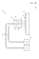
- the foreign matter inspection / removal device 100 removes foreign matter adhering to the surface W1 of the substrate W to be inspected and removed, and as shown in FIG. 1, foreign matter is removed. It includes an inspection device M1, a foreign matter removing device M2, and a control unit C. The foreign matter inspection device M1 and the foreign matter removal device M2 are juxtaposed with each other, and the substrate W can be delivered by a transport mechanism (not shown).
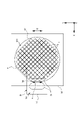
- the substrate W has a disk shape, and an orientation flat F (hereinafter, also referred to as an orientation flat F) formed by cutting out a part of the outer periphery thereof in a straight line. Will be described as having.
- an orientation flat F hereinafter, also referred to as an orientation flat F
- a plurality of structures T are arranged vertically and horizontally with the stretching direction of the orientation flat F as the horizontal direction and the direction orthogonal to the stretching direction as the vertical direction.
- the structure is along the surface W1 of W, and the strength against the force applied from the diagonal direction D with respect to the arrangement direction is lower than the strength against the force applied from another direction (direction different from the diagonal direction D). It is assumed that it has become. Therefore, the diagonal direction D corresponds to the predetermined direction in the claims.
- the foreign matter inspection device M1 is a light scattering type for acquiring foreign matter information such as the presence / absence, size, and position of foreign matter adhering to the surface W1 of the substrate W. Specifically, as shown in FIG. 2, the foreign matter inspection device M1 irradiates the inspection moving stage 10 on which the substrate W is mounted and the surface W1 of the substrate W mounted on the inspection moving stage 10 with inspection light. It includes a light irradiation unit 11 for scanning, and a light detection unit 12 for detecting reflected scattered light from the surface W1 of the substrate W irradiated with inspection light.
- the foreign matter removing device M2 blows off the foreign matter adhering to the surface W1 of the substrate W by blowing gas, and sucks and removes the blown off foreign matter.
- the foreign matter removing device M2 is arranged so as to face the removing moving stage 20 on which the substrate W is mounted and the substrate W mounted on the removing moving stage 20. It is equipped with a nozzle N.
- the gas is, for example, air, an inert gas, a gas mixed with droplets, or the like.
- the removal moving stage 20 is movable in the X direction, the Y direction, and the Z direction, and moves the substrate W relative to the nozzle N. Therefore, the removal moving stage 20 corresponds to the moving mechanism in the claim.
- the substrate W is positioned and placed on the removal moving stage 20 so that the arrangement directions of the plurality of structures T are oblique with respect to the X direction and the Y direction. That is, the substrate W is positioned and placed on the removal moving stage 20 so that the stretching direction of the orientation flat F is slanted with respect to the X direction and the Y direction.
- the substrate W is parallel to the moving direction (specifically, the Y direction) of the removing moving stage 20 in the oblique direction D, which is the structurally weak direction of the structure T. It is placed like this.
- the nozzle N includes a nozzle body 30 and a mask member 40.
- the nozzle body 30 includes a blowout flow path 31 through which a gas blown out to the outside flows, and a pair of suction flow paths 32 through which the gas sucked into the inside flows. Further, the nozzle body 30 is provided on the surface 33 facing the surface W1 of the substrate W mounted on the removal moving stage 20, the outlet 34 formed at the tip of the outlet flow path 31, and the tip of the suction flow path 32. The formed suction port 35 is provided.
- a blower 50 installed outside the foreign matter removing device M2 is connected to the blowout flow path 31 via a pipe P at the other end on the opposite side of the tip on which the blowout port 34 is formed. Further, a suction machine 60 installed outside the foreign matter removing device M2 is connected to the suction flow path 32 via a pipe P at the other end opposite to the tip on which the suction port 35 is formed.
- the outlet 34 has a long rectangular shape. Specifically, the outlet 34 is formed by partially closing the tip of the outlet flow path 31 with a mask member 40, and is composed of a plurality of opening elements 34h. As for the opening ratio of the outlet 34, the opening ratio of both end portions 34y is smaller than the opening ratio of the central portion 34x. Specifically, the opening ratio of the outlet 34 gradually decreases from the central portion 34x toward both ends.
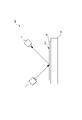
- the nozzle N is structurally weak in the structure T formed on the substrate W mounted on the removal moving stage 20 in a direction orthogonal to the direction connecting both ends of the outlet 34 (hereinafter, both ends direction ⁇ ). It is arranged so as not to coincide with the diagonal direction D, which is the direction (see FIG. 4). In the present embodiment, the nozzle N is arranged so that both end directions ⁇ of the outlet 34 coincide with the oblique direction D.
- the plurality of opening elements 34h provided in the central portion 34x all have the same opening area, and are arranged at equal intervals along both end directions ⁇ of the outlet 34. Therefore, the opening ratio of the central portion 34x of the outlet 34 is the same along the both end directions ⁇ of the outlet 34.
- the number of opening elements 34h having the same opening area arranged in a direction orthogonal to both end directions ⁇ of the outlet 34 increases toward both ends of the outlet 34. Further, the closer to both ends of the outlet 34, the smaller the opening area of the opening element 34h. Then, the total opening area of the plurality of opening elements 34h arranged in the direction orthogonal to the both ends direction ⁇ of the air outlet 34 becomes smaller toward both ends. Specifically, the total decreases at the same rate of change toward both ends. Therefore, the aperture ratio of both end portions 34y of the outlet 34 decreases at the same rate of change from the central portion 34x side of the outlet 34 toward both end portions.
- the plurality of opening elements 34h are provided symmetrically with respect to the center of the outlet 34 in the both ends direction ⁇ , and are provided symmetrically with respect to the center in the direction orthogonal to the both ends direction ⁇ of the outlet 34. Has been done. Therefore, both end portions 34y of the outlet 34 have the same length in both end directions ⁇ . The lengths of both end portions 34y of the outlet 34 in both end directions ⁇ are shorter than the lengths of the central portion 34x in both end directions.
- Both suction ports 35 are arranged so that their longitudinal directions coincide with the directions ⁇ at both ends of the outlet 34, and are formed on both sides of the outlet 34. Further, both suction ports 35 are formed at positions separated from the outlet 34 by the same distance.
- the mask member 40 has a plurality of obstruction plates 41, 42, and a part of a slit-shaped main outlet 36 having the same width formed at the tip of the outlet flow path 31 by the plurality of obstruction plates 41, 42. It is closed to form an outlet 34.
- the mask member 40 is installed at the tip of the outlet flow path 31 at intervals in the direction of both ends of the outlet 34, and is installed in a direction orthogonal to the direction of both ends (of the outlet 34). It includes a first closing plate 41 extending in the width direction) and a second closing plate 42 installed between adjacent first closing plates 41 and extending in the direction of both ends. Further, the first block plates 41 are provided at equal intervals in the direction of both ends of the outlet 34.
- the number of the second block plates 42 increases as the number of the second block plates 42 increases between the adjacent first block plates 41 near both ends of the outlet 34.
- the mask member 40 divides the main outlet 36 by the closing plates 41 and 42 to form a plurality of opening elements 34h constituting the outlet 34.
- the control unit C is a so-called computer connected to a foreign matter inspection device M1 and a foreign matter removal device M2 to control both devices M1 and M2.
- the control unit C includes a CPU, an internal memory, an external memory, an input / output interface, an AD converter, and the like, and the CPU and the CPU are based on a program stored in a predetermined area of the internal memory or the external memory.
- the peripheral device or the like when operated, it is configured to exert functions as a foreign matter inspection control unit C1, a foreign matter information calculation unit C2, a foreign matter removal control unit C3, and the like.
- the foreign matter inspection control unit C1 outputs a control signal to the inspection moving stage 10 and the light irradiation unit 11, controls the inspection moving stage 10 to move in a predetermined direction at a constant speed during the inspection, and moves the control signal.
- the scanning of the inspection light by the light irradiation unit 11 is controlled according to the above.
- the foreign matter information calculation unit C2 receives a control signal output from the foreign matter inspection control unit C1 to the inspection moving stage 10 and the light irradiation unit 11, and the irradiation indicating the light irradiation position on the surface W1 of the substrate W based on the control signal. It calculates the position data. Further, the foreign matter information calculation unit C2 receives the light intensity signal of the reflected scattered light when the inspection light is irradiated to the light irradiation position indicated by the irradiation position data from the light detection unit 12, and obtains the irradiation position data and the light intensity signal. Based on this, foreign matter information on the surface W1 of the substrate W is calculated.
- the foreign matter information includes the presence or absence of foreign matter on the surface W1 of the substrate W, the size and position of the foreign matter, and the like.
- the foreign matter removal control unit C3 receives foreign matter information data indicating foreign matter information from the foreign matter information calculation unit C2, and controls the blower 50, the suction machine 60, and the removal moving stage 20 based on the foreign matter information data. .. Specifically, the foreign matter removal control unit C3 determines whether or not the foreign matter adhering to the surface W1 of the substrate W corresponds to the removal target based on the foreign matter information data, and if it is determined to correspond to the removal target, the foreign matter removal control unit C3 determines. While controlling the removal moving stage 20 to move relative to the air outlet 34 and the substrate W, the blower 50 is controlled to blow the gas blown out from the air outlet 34 onto the substrate W to blow off the adhering foreign matter, and the suction machine. 60 is controlled to suck the foreign matter blown off from the suction port 45.
- the substrate W is placed on the inspection moving stage 10 of the foreign matter inspection device M1.
- the foreign matter inspection control unit C1 controls the inspection moving stage 10 and the light irradiation unit 11 to irradiate the entire surface W1 of the substrate W with the inspection light and scan. Then, during this scanning, the foreign matter information calculation unit C2 receives the control signal of the foreign matter inspection control unit C1 and the light intensity signal detected by the light detection unit 12, and calculates the foreign matter information on the surface W1 of the substrate W.
- the substrate W placed on the inspection moving stage 10 is conveyed to the removal moving stage 20 by the conveying mechanism.
- the arrangement direction of the structures T on the removal moving stage 20 is relative to the X direction and the Y direction in which the removal moving stage 20 is moved. Positioned at an angle.
- the foreign matter removal control unit C3 receives the foreign matter information data from the foreign matter information calculation unit C2, determines whether or not the foreign matter corresponds to the removal target, and if it determines that the foreign matter corresponds to the removal target, the blower 50, By controlling the suction machine 60 and the removal moving stage 20, gas is blown onto the foreign matter adhering to the surface W1 of the substrate W to remove the foreign matter. Specifically, the foreign matter removal control unit C3 moves the air outlet 34 in a zigzag manner with respect to the substrate W by relatively moving the air outlet 34 and the substrate W to remove the foreign matter.
- the foreign matter removal control unit C3 has an operation of blowing the gas blown out from the outlet 34 onto the substrate W while moving the outlet 34 in the X direction with respect to the substrate W to remove the foreign matter, and the substrate.
- the operation of moving the outlet 34 in the Y direction with respect to W is alternately repeated, and the operation of removing foreign matter is performed on the entire surface W1 of the substrate W.
- the nozzle N moves with respect to the substrate W while maintaining a state in which both ends of the outlet 34 are arranged in parallel with the diagonal direction D, which is a structurally weak direction of the structure T.
- the substrate W placed on the removal moving stage 20 is conveyed again by the conveying mechanism to the inspection moving stage 10, and it is inspected whether or not the foreign matter adhering to the surface W1 of the substrate W is removed by the foreign matter inspection device M1. do.
- the reliability of foreign matter removal can be improved.
- the opening ratio of the slit-shaped outlet 34 gradually decreases from the central portion 34x toward both ends, so that the flow rate of the gas blown out from the opening element 34h of the outlet 34 is the central portion 34x. It gradually becomes smaller from to both ends.
- the flow rate or flow velocity of the gas flowing in the other direction is compared with the flow rate or flow velocity of the gas flowing in the direction orthogonal to the both ends direction ⁇ of the outlet 34. Can be made as small as possible.
- the foreign matter removing device is compared with the conventional foreign matter removing device. Therefore, the flow rate or flow velocity of the gas that hits the structure T from a predetermined direction can be reduced, and the structure is less likely to be damaged.
- the flow rate or flow rate of the gas blown out from the outlet 34 while maintaining the flow rate or flow velocity of the gas that hits the structure T from the oblique direction D to the extent that the structure T is not damaged. Since the flow velocity can be increased, the foreign matter removal performance can be improved.
- the outlet may be composed of a plurality of opening elements or may be composed of one opening element. Further, the opening element of the outlet may be formed by a mask member or may be formed by the tip of the outlet flow path. That is, it may be formed on the nozzle body itself.
- the outlet may not be long, such as a square shape or a circular shape. Further, in the long air outlet, the opening ratio at both ends in the width direction may be smaller than the opening ratio at the center.
- the outlet 34 may have one opening element 34h, and the opening element 34h may be tapered toward both ends. In this way, the aperture ratio may be continuously reduced from the central portion 34x of the outlet 34 toward both ends.
- the opening element of the outlet may be asymmetric with respect to either or both of the center of the outlet in the direction of both ends or the center in the direction orthogonal to the directions of both ends.
- the outlet may have a length of both ends in the direction of both ends equal to or longer than the length of the central portion in the direction of both ends. Further, the lengths of both ends in the direction of both ends may be different from each other.
- the nozzle may not be provided with a suction port.
- the foreign matter removing device may be one in which the nozzle moves instead of the removing moving stage, and both the removing moving stage and the nozzle may move.
- the foreign matter inspection device may be a transmission type.
- either one of the light irradiation unit and the photodetection unit is installed on the front surface side of the substrate, the other is installed on the back surface side of the substrate, and the light emitted from the light irradiation unit to the substrate surface and transmitted through the substrate is emitted. It may be configured to be detected by the detection unit.
- the air outlet is moved to directly above the position where the foreign matter on the substrate is detected. After that, the gas blown out from the air outlet may be blown onto the substrate to remove the foreign matter.
Landscapes
- Physics & Mathematics (AREA)
- Health & Medical Sciences (AREA)
- Life Sciences & Earth Sciences (AREA)
- Chemical & Material Sciences (AREA)
- Analytical Chemistry (AREA)
- Biochemistry (AREA)
- General Health & Medical Sciences (AREA)
- General Physics & Mathematics (AREA)
- Immunology (AREA)
- Pathology (AREA)
- Cleaning Or Drying Semiconductors (AREA)
- Cleaning In General (AREA)
Abstract
Description
W 基板(対象物)
W1 表面
T 構造物
D 斜め方向(所定方向)
M1 異物検査装置
M2 異物除去装置
N ノズル
30 ノズル本体
34 吹出口
34h 開口要素
34x 中央部
34y 両端部
α 両端方向
40 マスク部材
41 第1閉塞板
42 第2閉塞板
本発明に係る異物除去装置は、例えば異物検査除去装置を構成するものとして使用される。この異物検査除去装置は、例えば、複数の構造物(例えば、トランジスタ、配線等)が縦横に並べて形成された半導体基板W(例えば、Siウエハ、SiCウエハなど)の表面W1に付着した異物の検査及び除去を行うものである。なお、異物検査除去装置は、半導体基板に限定されず、表面に所定方向から加わる力によってダメージを受け易い構造物が形成されたものに使用することができ、例えば、絶縁体基板(例えば、サファイア基板など)、これらの基板から切り出したチップ(例えば、MEMS、センサー素子、SAWデバイスなど)、又は、電子部品(例えば、HDD素子など)等にも使用できる。なお、異物除去装置は、それ単独でも使用できる。
Claims (9)
- 対象物に付着した異物を吹出口が形成されたノズルから吹き出される気体によって除去する異物除去装置であって、
前記吹出口の両端部の開口率が、当該吹出口の中央部の開口率よりも小さくなるように構成されていることを特徴とする異物除去装置。 - 前記開口率が、前記吹出口の前記中央部から両端へ向かって連続的又は段階的に小さくなるように構成されている請求項1記載の異物除去装置。
- 前記ノズルが、前記気体の流れる流路が形成されたノズル本体と、前記流路の先端を一部閉塞して前記吹出口を形成するマスク部材とを備えている請求項1又は2のいずれかに記載の異物除去装置。
- 前記吹出口が、閉塞板によって区切られた複数の開口要素からなるものである請求項3記載の異物除去装置。
- 前記マスク部材が、前記吹出口の両端方向と直交方向へ延び、当該両端方向に等間隔に設置された複数の第1閉塞板と、当該両端方向へ延び、隣り合う前記第1閉塞板の間に設置された第2閉塞板とを備え、
前記第2閉塞板の数が、前記吹出口の両端に近い前記隣り合う第1閉塞板の間ほど多くなっている請求項4記載の異物除去装置。 - 前記対象物が、複数の構造物が縦横に配列された半導体ウエハであり、
前記構造物は、所定方向から加わる力に対する強度が当該所定方向と異なる方向から加わる力に対する強度に比べて低い構造のものであり、
前記ノズルは、前記吹出口の両端方向と直交する方向が前記所定方向と一致しないように配置されている請求項1乃至5のいずれかに記載の異物除去装置。 - 前記構造物が、その配列方向に対して斜め方向から加わる力に対する強度が当該斜め方向と異なる方向から加わる力に対する強度に比べて低い構造のものであり、
前記ノズルは、前記吹出口の両端方向と直交する方向が前記斜め方向と一致しないように配置されている請求項6記載の異物除去装置。 - 前記対象物と前記ノズルとを相対移動させる移動機構をさらに備えている請求項1乃至7のいずれかに記載の異物除去装置。
- 複数の構造物が縦横に配列された対象物の表面に付着した異物を、吹出口が形成されたノズルから吹き出される気体によって除去する異物除去方法であって、
前記構造物は、所定方向から加わる力に対する強度が当該所定方向と異なる方向から加わる力に対する強度に比べて低い構造のものであり、
前記吹出口の両端部の開口率が、当該吹出口の中央部の開口率よりも小さくなっており、
前記ノズルを前記吹出口の両端方向と直交する方向が前記所定方向と一致しないように配置することを特徴とする異物除去方法。
Priority Applications (4)
| Application Number | Priority Date | Filing Date | Title |
|---|---|---|---|
| CN202180064157.9A CN116323018B (zh) | 2020-09-24 | 2021-08-26 | 异物除去装置和异物除去方法 |
| JP2022551218A JP7473664B2 (ja) | 2020-09-24 | 2021-08-26 | 異物除去装置及び異物除去方法 |
| KR1020237011915A KR102950096B1 (ko) | 2020-09-24 | 2021-08-26 | 이물 제거 장치 및 이물 제거 방법 |
| US18/027,257 US20230338994A1 (en) | 2020-09-24 | 2021-08-26 | Contaminant removal device and contaminant removal method |
Applications Claiming Priority (2)
| Application Number | Priority Date | Filing Date | Title |
|---|---|---|---|
| JP2020159394 | 2020-09-24 | ||
| JP2020-159394 | 2020-09-24 |
Publications (1)
| Publication Number | Publication Date |
|---|---|
| WO2022064950A1 true WO2022064950A1 (ja) | 2022-03-31 |
Family
ID=80845147
Family Applications (1)
| Application Number | Title | Priority Date | Filing Date |
|---|---|---|---|
| PCT/JP2021/031402 Ceased WO2022064950A1 (ja) | 2020-09-24 | 2021-08-26 | 異物除去装置及び異物除去方法 |
Country Status (5)
| Country | Link |
|---|---|
| US (1) | US20230338994A1 (ja) |
| JP (1) | JP7473664B2 (ja) |
| KR (1) | KR102950096B1 (ja) |
| CN (1) | CN116323018B (ja) |
| WO (1) | WO2022064950A1 (ja) |
Citations (3)
| Publication number | Priority date | Publication date | Assignee | Title |
|---|---|---|---|---|
| JPH1070069A (ja) * | 1996-08-28 | 1998-03-10 | Canon Inc | 半導体露光装置におけるごみ検出装置 |
| JP2010210527A (ja) * | 2009-03-11 | 2010-09-24 | Horiba Ltd | 異物検査除去装置及び異物検査除去プログラム |
| JP2016201457A (ja) * | 2015-04-09 | 2016-12-01 | 東京エレクトロン株式会社 | 異物除去装置、異物除去方法および剥離装置 |
Family Cites Families (10)
| Publication number | Priority date | Publication date | Assignee | Title |
|---|---|---|---|---|
| US5596783A (en) | 1995-06-07 | 1997-01-28 | Electrostatics, Inc. | Sheet and web cleaner with face plate on suction hood |
| US6941606B2 (en) | 2002-07-02 | 2005-09-13 | Electrostatics, Incorporated | Sheet and web cleaner on suction hood |
| US6921438B2 (en) | 2002-07-30 | 2005-07-26 | John Lausevic | Vacuum cleaner attachment for fungi removal and method of use thereof |
| KR100568104B1 (ko) * | 2003-08-26 | 2006-04-05 | 삼성전자주식회사 | 반도체 기판 세정 장치 및 세정 방법 |
| US7111797B2 (en) | 2004-03-22 | 2006-09-26 | International Business Machines Corporation | Non-contact fluid particle cleaner and method |
| JP4972274B2 (ja) * | 2004-09-17 | 2012-07-11 | 株式会社共立合金製作所 | 噴霧ノズル |
| KR100739425B1 (ko) * | 2006-02-21 | 2007-07-13 | 김종련 | 2 유체를 혼합하기 위한 제트노즐과 이를 이용한 세정 장치 |
| JP2010000486A (ja) * | 2008-06-23 | 2010-01-07 | Sunx Ltd | 除電除塵装置 |
| JP5405865B2 (ja) * | 2009-03-23 | 2014-02-05 | 株式会社共立合金製作所 | 噴射ノズル |
| JP7529409B2 (ja) * | 2020-02-18 | 2024-08-06 | 株式会社テクノ菱和 | 除塵ノズルおよび除塵装置 |
-
2021
- 2021-08-26 JP JP2022551218A patent/JP7473664B2/ja active Active
- 2021-08-26 WO PCT/JP2021/031402 patent/WO2022064950A1/ja not_active Ceased
- 2021-08-26 US US18/027,257 patent/US20230338994A1/en active Pending
- 2021-08-26 CN CN202180064157.9A patent/CN116323018B/zh active Active
- 2021-08-26 KR KR1020237011915A patent/KR102950096B1/ko active Active
Patent Citations (3)
| Publication number | Priority date | Publication date | Assignee | Title |
|---|---|---|---|---|
| JPH1070069A (ja) * | 1996-08-28 | 1998-03-10 | Canon Inc | 半導体露光装置におけるごみ検出装置 |
| JP2010210527A (ja) * | 2009-03-11 | 2010-09-24 | Horiba Ltd | 異物検査除去装置及び異物検査除去プログラム |
| JP2016201457A (ja) * | 2015-04-09 | 2016-12-01 | 東京エレクトロン株式会社 | 異物除去装置、異物除去方法および剥離装置 |
Also Published As
| Publication number | Publication date |
|---|---|
| JP7473664B2 (ja) | 2024-04-23 |
| US20230338994A1 (en) | 2023-10-26 |
| CN116323018B (zh) | 2025-10-28 |
| CN116323018A (zh) | 2023-06-23 |
| KR20230064624A (ko) | 2023-05-10 |
| JPWO2022064950A1 (ja) | 2022-03-31 |
| KR102950096B1 (ko) | 2026-04-09 |
Similar Documents
| Publication | Publication Date | Title |
|---|---|---|
| US8279432B2 (en) | Particle inspection and removal apparatus and particle inspection and removal program | |
| US6327021B1 (en) | Mask inspection system and method of manufacturing semiconductor device | |
| TW201236728A (en) | Coating apparatus and coating method | |
| JP4593243B2 (ja) | 気中粒子監視装置および真空処理装置 | |
| CN108857056B (zh) | 激光加工装置 | |
| WO2022064950A1 (ja) | 異物除去装置及び異物除去方法 | |
| KR100493847B1 (ko) | 파티클을 검출하기 위한 장치 및 방법 | |
| US9759669B2 (en) | Inspection device | |
| JP4413831B2 (ja) | ウェハ表面検査装置及びウェハ表面検査方法 | |
| JP2020032362A (ja) | 基板処理装置および基板処理方法 | |
| JP7705325B2 (ja) | 基板処理装置および基板処理方法 | |
| JP5314369B2 (ja) | 欠陥検査装置 | |
| JPH1144634A (ja) | 検出器のエアパージ機構 | |
| JP2013163216A (ja) | レーザー加工装置 | |
| TWI802254B (zh) | 雷射光導入裝置 | |
| JP7224992B2 (ja) | 集塵装置及びレーザ加工装置 | |
| CN112868093B (zh) | 检查装置 | |
| JP2005114707A (ja) | 部品姿勢の判別方法及び部品搬送装置 | |
| JP2008039419A (ja) | パターン欠陥検査装置 | |
| JP2014136238A (ja) | レーザー加工装置 | |
| JP2004295085A5 (ja) | ||
| JPH09306883A (ja) | 半導体製造装置 | |
| JP2004295085A (ja) | 描画装置 | |
| JP2007173532A (ja) | 基板処理装置 | |
| JPH03242510A (ja) | チップ部品欠け認識装置 |
Legal Events
| Date | Code | Title | Description |
|---|---|---|---|
| 121 | Ep: the epo has been informed by wipo that ep was designated in this application |
Ref document number: 21872082 Country of ref document: EP Kind code of ref document: A1 |
|
| ENP | Entry into the national phase |
Ref document number: 2022551218 Country of ref document: JP Kind code of ref document: A |
|
| ENP | Entry into the national phase |
Ref document number: 20237011915 Country of ref document: KR Kind code of ref document: A |
|
| NENP | Non-entry into the national phase |
Ref country code: DE |
|
| 122 | Ep: pct application non-entry in european phase |
Ref document number: 21872082 Country of ref document: EP Kind code of ref document: A1 |
|
| WWG | Wipo information: grant in national office |
Ref document number: 202180064157.9 Country of ref document: CN |