WO2022064643A1 - 高耐食ステンレス鋼部品およびその製造方法、ステンレス鋼部品の熱処理方法、ならびに転がり軸受およびその製造方法 - Google Patents
高耐食ステンレス鋼部品およびその製造方法、ステンレス鋼部品の熱処理方法、ならびに転がり軸受およびその製造方法 Download PDFInfo
- Publication number
- WO2022064643A1 WO2022064643A1 PCT/JP2020/036329 JP2020036329W WO2022064643A1 WO 2022064643 A1 WO2022064643 A1 WO 2022064643A1 JP 2020036329 W JP2020036329 W JP 2020036329W WO 2022064643 A1 WO2022064643 A1 WO 2022064643A1
- Authority
- WO
- WIPO (PCT)
- Prior art keywords
- stainless steel
- highly corrosion
- less
- resistant stainless
- rolling bearing
- Prior art date
- Legal status (The legal status is an assumption and is not a legal conclusion. Google has not performed a legal analysis and makes no representation as to the accuracy of the status listed.)
- Ceased
Links
Images



Classifications
-
- C—CHEMISTRY; METALLURGY
- C22—METALLURGY; FERROUS OR NON-FERROUS ALLOYS; TREATMENT OF ALLOYS OR NON-FERROUS METALS
- C22C—ALLOYS
- C22C38/00—Ferrous alloys, e.g. steel alloys
- C22C38/18—Ferrous alloys, e.g. steel alloys containing chromium
- C22C38/22—Ferrous alloys, e.g. steel alloys containing chromium with molybdenum or tungsten
-
- C—CHEMISTRY; METALLURGY
- C21—METALLURGY OF IRON
- C21D—MODIFYING THE PHYSICAL STRUCTURE OF FERROUS METALS; GENERAL DEVICES FOR HEAT TREATMENT OF FERROUS OR NON-FERROUS METALS OR ALLOYS; MAKING METAL MALLEABLE, e.g. BY DECARBURISATION OR TEMPERING
- C21D1/00—General methods or devices for heat treatment, e.g. annealing, hardening, quenching or tempering
- C21D1/18—Hardening; Quenching with or without subsequent tempering
-
- C—CHEMISTRY; METALLURGY
- C21—METALLURGY OF IRON
- C21D—MODIFYING THE PHYSICAL STRUCTURE OF FERROUS METALS; GENERAL DEVICES FOR HEAT TREATMENT OF FERROUS OR NON-FERROUS METALS OR ALLOYS; MAKING METAL MALLEABLE, e.g. BY DECARBURISATION OR TEMPERING
- C21D1/00—General methods or devices for heat treatment, e.g. annealing, hardening, quenching or tempering
- C21D1/26—Methods of annealing
-
- C—CHEMISTRY; METALLURGY
- C21—METALLURGY OF IRON
- C21D—MODIFYING THE PHYSICAL STRUCTURE OF FERROUS METALS; GENERAL DEVICES FOR HEAT TREATMENT OF FERROUS OR NON-FERROUS METALS OR ALLOYS; MAKING METAL MALLEABLE, e.g. BY DECARBURISATION OR TEMPERING
- C21D1/00—General methods or devices for heat treatment, e.g. annealing, hardening, quenching or tempering
- C21D1/74—Methods of treatment in inert gas, controlled atmosphere, vacuum or pulverulent material
- C21D1/76—Adjusting the composition of the atmosphere
-
- C—CHEMISTRY; METALLURGY
- C21—METALLURGY OF IRON
- C21D—MODIFYING THE PHYSICAL STRUCTURE OF FERROUS METALS; GENERAL DEVICES FOR HEAT TREATMENT OF FERROUS OR NON-FERROUS METALS OR ALLOYS; MAKING METAL MALLEABLE, e.g. BY DECARBURISATION OR TEMPERING
- C21D6/00—Heat treatment of ferrous alloys
- C21D6/002—Heat treatment of ferrous alloys containing Cr
-
- C—CHEMISTRY; METALLURGY
- C21—METALLURGY OF IRON
- C21D—MODIFYING THE PHYSICAL STRUCTURE OF FERROUS METALS; GENERAL DEVICES FOR HEAT TREATMENT OF FERROUS OR NON-FERROUS METALS OR ALLOYS; MAKING METAL MALLEABLE, e.g. BY DECARBURISATION OR TEMPERING
- C21D6/00—Heat treatment of ferrous alloys
- C21D6/005—Heat treatment of ferrous alloys containing Mn
-
- C—CHEMISTRY; METALLURGY
- C21—METALLURGY OF IRON
- C21D—MODIFYING THE PHYSICAL STRUCTURE OF FERROUS METALS; GENERAL DEVICES FOR HEAT TREATMENT OF FERROUS OR NON-FERROUS METALS OR ALLOYS; MAKING METAL MALLEABLE, e.g. BY DECARBURISATION OR TEMPERING
- C21D6/00—Heat treatment of ferrous alloys
- C21D6/008—Heat treatment of ferrous alloys containing Si
-
- C—CHEMISTRY; METALLURGY
- C21—METALLURGY OF IRON
- C21D—MODIFYING THE PHYSICAL STRUCTURE OF FERROUS METALS; GENERAL DEVICES FOR HEAT TREATMENT OF FERROUS OR NON-FERROUS METALS OR ALLOYS; MAKING METAL MALLEABLE, e.g. BY DECARBURISATION OR TEMPERING
- C21D6/00—Heat treatment of ferrous alloys
- C21D6/04—Hardening by cooling below 0 degrees Celsius
-
- C—CHEMISTRY; METALLURGY
- C21—METALLURGY OF IRON
- C21D—MODIFYING THE PHYSICAL STRUCTURE OF FERROUS METALS; GENERAL DEVICES FOR HEAT TREATMENT OF FERROUS OR NON-FERROUS METALS OR ALLOYS; MAKING METAL MALLEABLE, e.g. BY DECARBURISATION OR TEMPERING
- C21D9/00—Heat treatment, e.g. annealing, hardening, quenching or tempering, adapted for particular articles; Furnaces therefor
- C21D9/40—Heat treatment, e.g. annealing, hardening, quenching or tempering, adapted for particular articles; Furnaces therefor for rings; for bearing races
-
- C—CHEMISTRY; METALLURGY
- C22—METALLURGY; FERROUS OR NON-FERROUS ALLOYS; TREATMENT OF ALLOYS OR NON-FERROUS METALS
- C22C—ALLOYS
- C22C38/00—Ferrous alloys, e.g. steel alloys
- C22C38/001—Ferrous alloys, e.g. steel alloys containing N
-
- C—CHEMISTRY; METALLURGY
- C22—METALLURGY; FERROUS OR NON-FERROUS ALLOYS; TREATMENT OF ALLOYS OR NON-FERROUS METALS
- C22C—ALLOYS
- C22C38/00—Ferrous alloys, e.g. steel alloys
- C22C38/002—Ferrous alloys, e.g. steel alloys containing In, Mg, or other elements not provided for in one single group C22C38/001 - C22C38/60
-
- C—CHEMISTRY; METALLURGY
- C22—METALLURGY; FERROUS OR NON-FERROUS ALLOYS; TREATMENT OF ALLOYS OR NON-FERROUS METALS
- C22C—ALLOYS
- C22C38/00—Ferrous alloys, e.g. steel alloys
- C22C38/02—Ferrous alloys, e.g. steel alloys containing silicon
-
- C—CHEMISTRY; METALLURGY
- C22—METALLURGY; FERROUS OR NON-FERROUS ALLOYS; TREATMENT OF ALLOYS OR NON-FERROUS METALS
- C22C—ALLOYS
- C22C38/00—Ferrous alloys, e.g. steel alloys
- C22C38/04—Ferrous alloys, e.g. steel alloys containing manganese
-
- C—CHEMISTRY; METALLURGY
- C22—METALLURGY; FERROUS OR NON-FERROUS ALLOYS; TREATMENT OF ALLOYS OR NON-FERROUS METALS
- C22C—ALLOYS
- C22C38/00—Ferrous alloys, e.g. steel alloys
- C22C38/18—Ferrous alloys, e.g. steel alloys containing chromium
- C22C38/32—Ferrous alloys, e.g. steel alloys containing chromium with boron
-
- F—MECHANICAL ENGINEERING; LIGHTING; HEATING; WEAPONS; BLASTING
- F16—ENGINEERING ELEMENTS AND UNITS; GENERAL MEASURES FOR PRODUCING AND MAINTAINING EFFECTIVE FUNCTIONING OF MACHINES OR INSTALLATIONS; THERMAL INSULATION IN GENERAL
- F16C—SHAFTS; FLEXIBLE SHAFTS; ELEMENTS OR CRANKSHAFT MECHANISMS; ROTARY BODIES OTHER THAN GEARING ELEMENTS; BEARINGS
- F16C33/00—Parts of bearings; Special methods for making bearings or parts thereof
- F16C33/30—Parts of ball or roller bearings
- F16C33/58—Raceways; Race rings
- F16C33/62—Selection of substances
-
- F—MECHANICAL ENGINEERING; LIGHTING; HEATING; WEAPONS; BLASTING
- F16—ENGINEERING ELEMENTS AND UNITS; GENERAL MEASURES FOR PRODUCING AND MAINTAINING EFFECTIVE FUNCTIONING OF MACHINES OR INSTALLATIONS; THERMAL INSULATION IN GENERAL
- F16C—SHAFTS; FLEXIBLE SHAFTS; ELEMENTS OR CRANKSHAFT MECHANISMS; ROTARY BODIES OTHER THAN GEARING ELEMENTS; BEARINGS
- F16C33/00—Parts of bearings; Special methods for making bearings or parts thereof
- F16C33/30—Parts of ball or roller bearings
- F16C33/58—Raceways; Race rings
- F16C33/64—Special methods of manufacture
-
- C—CHEMISTRY; METALLURGY
- C21—METALLURGY OF IRON
- C21D—MODIFYING THE PHYSICAL STRUCTURE OF FERROUS METALS; GENERAL DEVICES FOR HEAT TREATMENT OF FERROUS OR NON-FERROUS METALS OR ALLOYS; MAKING METAL MALLEABLE, e.g. BY DECARBURISATION OR TEMPERING
- C21D2211/00—Microstructure comprising significant phases
- C21D2211/001—Austenite
-
- C—CHEMISTRY; METALLURGY
- C21—METALLURGY OF IRON
- C21D—MODIFYING THE PHYSICAL STRUCTURE OF FERROUS METALS; GENERAL DEVICES FOR HEAT TREATMENT OF FERROUS OR NON-FERROUS METALS OR ALLOYS; MAKING METAL MALLEABLE, e.g. BY DECARBURISATION OR TEMPERING
- C21D2211/00—Microstructure comprising significant phases
- C21D2211/008—Martensite
-
- F—MECHANICAL ENGINEERING; LIGHTING; HEATING; WEAPONS; BLASTING
- F16—ENGINEERING ELEMENTS AND UNITS; GENERAL MEASURES FOR PRODUCING AND MAINTAINING EFFECTIVE FUNCTIONING OF MACHINES OR INSTALLATIONS; THERMAL INSULATION IN GENERAL
- F16C—SHAFTS; FLEXIBLE SHAFTS; ELEMENTS OR CRANKSHAFT MECHANISMS; ROTARY BODIES OTHER THAN GEARING ELEMENTS; BEARINGS
- F16C19/00—Bearings with rolling contact, for exclusively rotary movement
- F16C19/02—Bearings with rolling contact, for exclusively rotary movement with bearing balls essentially of the same size in one or more circular rows
- F16C19/04—Bearings with rolling contact, for exclusively rotary movement with bearing balls essentially of the same size in one or more circular rows for radial load mainly
- F16C19/06—Bearings with rolling contact, for exclusively rotary movement with bearing balls essentially of the same size in one or more circular rows for radial load mainly with a single row or balls
-
- F—MECHANICAL ENGINEERING; LIGHTING; HEATING; WEAPONS; BLASTING
- F16—ENGINEERING ELEMENTS AND UNITS; GENERAL MEASURES FOR PRODUCING AND MAINTAINING EFFECTIVE FUNCTIONING OF MACHINES OR INSTALLATIONS; THERMAL INSULATION IN GENERAL
- F16C—SHAFTS; FLEXIBLE SHAFTS; ELEMENTS OR CRANKSHAFT MECHANISMS; ROTARY BODIES OTHER THAN GEARING ELEMENTS; BEARINGS
- F16C2204/00—Metallic materials; Alloys
- F16C2204/60—Ferrous alloys, e.g. steel alloys
- F16C2204/62—Low carbon steel, i.e. carbon content below 0.4 wt%
-
- F—MECHANICAL ENGINEERING; LIGHTING; HEATING; WEAPONS; BLASTING
- F16—ENGINEERING ELEMENTS AND UNITS; GENERAL MEASURES FOR PRODUCING AND MAINTAINING EFFECTIVE FUNCTIONING OF MACHINES OR INSTALLATIONS; THERMAL INSULATION IN GENERAL
- F16C—SHAFTS; FLEXIBLE SHAFTS; ELEMENTS OR CRANKSHAFT MECHANISMS; ROTARY BODIES OTHER THAN GEARING ELEMENTS; BEARINGS
- F16C2204/00—Metallic materials; Alloys
- F16C2204/60—Ferrous alloys, e.g. steel alloys
- F16C2204/70—Ferrous alloys, e.g. steel alloys with chromium as the next major constituent
Definitions
- the present invention relates to a highly corrosion-resistant stainless steel part having excellent corrosion resistance.
- martensitic stainless steel typified by SUS440C is used as the bearing material.
- SUS440C contains 16 to 18% by weight of chromium that improves corrosion resistance
- the carbon content is as high as 0.95 to 1.2% by weight in order to secure the hardness, thereby producing about 20 ⁇ m of chromium carbide.
- Corrosion resistance is not so high because many are produced. Therefore, it is not suitable for use in a severely corrosive environment where it is exposed to strong alkaline disinfectants or seawater or rainwater.
- ferrite-based stainless steel and austenitic stainless steel are superior in corrosion resistance to martensitic stainless steel, but have low strength.
- austenitic stainless steel has a hardness of about HRC40 even when cold-worked. , It is rarely used for rolling bearings.
- the highly corrosion-resistant martensitic stainless steel disclosed in Patent Document 1 contains a large amount of nitrogen in a solid solution, and such a martensitic stainless steel in which a large amount of nitrogen is dissolved is a vacuum furnace in order to obtain a desired hardness. It is hardened inside. Chromium and molybdenum are elements that promote ferrite formation, while nitrogen is an austenite stabilizing element that suppresses ferrite formation. Therefore, if nitrogen in the surface layer portion escapes during vacuum quenching, the nitrogen concentration decreases and the ferrite suppressing effect weakens, and ferrite may be generated in the surface layer portion to obtain desired hardness.
- JIS B1511: 1993 which is a rolling bearing standard, requires that the hardness of the raceway ring of a rolling bearing is in the range of HRC57 to 65. It was confirmed that the hardness in the range (within 50 ⁇ m) may be less than HRC55.
- the solid solution limit of carbon is low.
- Ferrite has a solid solution limit of carbon of 727 ° C. and is only about 0.02% by weight. Therefore, when the austenite temperature range is cooled and ferrite begins to precipitate on the surface layer portion, carbon is released to the outside of the ferrite. As a result, carbon is concentrated around the ferrite to form chromium carbide. When the chromium around the ferrite is used as a carbide, it becomes a chromium-deficient layer, and as a result, there is a problem that the corrosion resistance around the ferrite is lowered.
- the present invention has been made in view of the above circumstances, and an object of the present invention is to provide a highly corrosion-resistant stainless steel component having both high corrosion resistance and high hardness without containing ferrite in the surface layer portion.
- the present inventor performs quenching of a highly corrosion-resistant martensitic stainless steel in which a large amount of nitrogen is dissolved by heating it to a temperature in the range of 1050 to 1120 ° C. in a nitrogen atmosphere having a nitrogen partial pressure of 1000 Pa or more and less than 10,000 Pa. As a result, it was found that the solid-solved nitrogen was suppressed from coming out from the surface layer portion and the ferrite structure was not formed on the surface layer portion.
- C is 0.35 to 0.43%
- Si is 0.5% or less
- Mn is 0.5% or less
- P is 0.04.
- % Or less S 0.04% or less
- B 0.001 to 0.005% N is contained in 0.12 to 0.18%
- the balance is made of highly corrosion-resistant martensitic stainless steel composed of Fe and unavoidable impurities
- the base structure of the surface layer of the entire outer surface contains retained austenite and martensitic.
- It is a highly corrosion-resistant stainless steel part having a phase-mixed structure and a surface hardness of HRC57 or higher.
- the "surface layer portion” refers to a range from the surface to a depth of about 50 ⁇ m.
- the base structure of the surface layer portion of the entire outer surface exhibits a two-phase mixed structure containing retained austenite and martensite, the area ratio of ferrite in the surface layer portion is zero, that is, ferrite is not present. ..
- a high surface hardness of HRC57 or higher can be obtained.
- carbon is not partially concentrated due to the absence of ferrite on the surface layer portion, the formation of a chromium-deficient layer due to the formation of chromium carbide is suppressed, so that corrosion resistance can be improved. ..
- Still another feature of the present invention is that C is 0.35 to 0.43%, Si is 0.5% or less, Mn is 0.5% or less, P is 0.04% or less, and S is S. 0.04% or less, Cr is 15 to 17%, W is 0.1 to 0.3%, Mo is 1.5 to 3.0%, B is 0.001 to 0.005%, and N is 0.
- a method for heat-treating a highly corrosion-resistant stainless steel part which comprises a step of heating to a temperature in the range of 1050 to 1120 ° C. and quenching.
- Still another feature of the present invention is a method for manufacturing a highly corrosion-resistant stainless steel part, including a method for heat-treating the highly corrosion-resistant stainless steel part.
- ⁇ C 0.35 to 0.43% C is an effective component for ensuring the hardness (wear resistance) of steel parts, but since it is also an austenite-forming element, if it is added in a large amount, eutectic carbides are likely to be generated and cracks are likely to occur. Further, since excessive addition also deteriorates the corrosion resistance, the upper limit was 0.43%, which was confirmed to have good corrosion resistance. Then, the lower limit was 0.35%, in which ferrite was not generated on the surface layer portion after the heat treatment and a hardness of HRC57 or higher was obtained.
- Mn is an austenite stabilizing element, and excessive addition increases the amount of retained austenite, which reduces the hardness after heat treatment, deteriorates corrosion resistance, and causes dimensional changes over time. Easy to wake up. Therefore, it is better that the amount of Mn is small, but the content is set to 0.5% or less in consideration of the production cost.
- P is a component that precipitates at grain boundaries and causes cold brittleness, so it is desirable that it be as small as possible in order to avoid cold brittleness, but the content is in consideration of manufacturing costs.
- ⁇ Cr 15 to 17% Since Cr forms a strong non-conductor coating for stainless steel, it is an indispensable element for obtaining high corrosion resistance, and a large amount of Cr needs to be added. According to the salt spray test results, when the Cr content was less than 15%, 15% was set as the lower limit because good corrosion resistance could not be obtained even if the N content was sufficient, as will be described later. However, Cr can also be a factor that inhibits martensitic formation by forming ferrite. When the Cr content exceeds 17%, ferrite is formed on the surface layer portion after quenching, which causes a decrease in hardness. Therefore, the upper limit is 17%.
- Mo has the effect of increasing the solid solution limit of N, improving the corrosion resistance, and improving the hardenability. In order to obtain such an effect, it is necessary to add 1.5% or more. However, excessive addition causes a decrease in toughness and ferrite formation near the surface layer, so the upper limit was 3.0%.
- N is a very effective element for improving the surface hardness and corrosion resistance of martensitic stainless steel after heat treatment.
- the content of N needs to be 0.12% or more.
- the martensitic stainless steel that can be put into practical use has a solid solution limit of 0.18% because it is more economical than the pressure melting method and does not generate blows (bubbles) in the material. , 0.18% was the upper limit. This reduced the manufacturing cost.
- ⁇ W 0.1% to 0.3% W is a component that improves corrosion resistance and acts as a solid solution strengthening element to contribute to the improvement of strength. In order to obtain this effect, it is necessary to add 0.1% or more. On the other hand, excessive addition causes a decrease in toughness, so the upper limit was 0.3% at which no problem performance was obtained.
- the base structure is preferably a two-phase mixed structure containing 13% by volume or less of retained austenite and the balance of martensite. By suppressing the soft retained austenite to 13% by volume or less and using martensite as the balance, it is possible to secure a hardness of HRC57 or higher.
- the base structure refers to the structure of the base (matrix) excluding carbides, nitrides and inclusions.
- FIG. 1 is a cross-sectional view showing a rolling bearing (deep groove ball bearing, assembly) 10 according to an embodiment of the present invention.
- the rolling bearing 10 has an outer ring 1 and an inner ring 2 as raceway rings.
- a raceway groove 1a having an arc-shaped cross section is formed on the inner peripheral surface of the outer ring 1
- a raceway groove 2a having an arc-shaped cross section is formed on the outer peripheral surface of the inner ring 2.
- a plurality of balls 3 are arranged at equal intervals along the circumferential direction as rolling elements. The plurality of balls 3 are each held in the plurality of pockets of the cage 4.
- the cage 4 can be formed of a resin or metal such as polyamide or polyetheretherketone. Further, the type of the cage 4 is not particularly limited, and any shape such as a crown type cage, a punching cage, and a corrugated cage can be selected.
- the cage 4 in FIG. 1 is a crown-type cage.
- the bearing space 5 between the outer ring 1 and the inner ring 2 is sealed with a metal sealing member 6 (metal shield).
- the seal member 6 is not limited to the metal shield, and a non-contact type or contact type rubber seal can also be used.
- grease is sealed in the bearing space 5 as a lubricant.
- the grease used is selected according to the application of the rolling bearing 10. Typical greases include, but are not limited to, lithium soap grease and urea grease.
- the outer ring 1 and the inner ring 2 are made of highly corrosion-resistant martensitic stainless steel. Further, the outer ring 1 and the inner ring 2 are subjected to heat treatment according to the present invention including quenching, subzero treatment and tempering.
- the base structure of the surface layer portion over the entire surface of the outer ring 1 and the inner ring 2 is composed of martensite and retained austenite of 13% by volume or less, and ferrite is not produced.
- the area ratio of ferrite in the surface layer portion over the entire surfaces of the outer ring 1 and the inner ring 2 is zero.
- the hardness of the surface and the inside is increased to HRC57 or higher.
- high corrosion resistance may be required only for the outer ring or the inner ring.
- the highly corrosion-resistant stainless steel parts according to the present invention may be used only for the outer ring or only the inner ring.
- the outer ring is mainly exposed to rainwater or muddy water, so that the outer ring is required to have higher corrosion resistance.
- the ball 3 can be made of metal or ceramics.
- the rolling element of the rolling bearing is not limited to the spherical ball 3, and the rolling element may be a cylindrical roller and the rolling bearing may be a roller bearing.
- the material can be the same highly corrosion-resistant martensitic stainless steel as the outer ring 1 and the inner ring 2. As a result, the ball 3 having corrosion resistance and hardness equal to or higher than that of the outer ring 1 and the inner ring 2 can be obtained.
- the ball 3 is rust-proofed to some extent by grease, so that bearing steel (for example, SUJ2) or conventional martensitic stainless steel for bearings, which is inferior in corrosion resistance to highly corrosion-resistant martensitic stainless steel, or conventional martensitic stainless steel for bearings. Martensitic stainless steel (for example, SUS440C) may be used.
- bearing steel for example, SUJ2
- conventional martensitic stainless steel for bearings which is inferior in corrosion resistance to highly corrosion-resistant martensitic stainless steel, or conventional martensitic stainless steel for bearings.
- Martensitic stainless steel for example, SUS440C
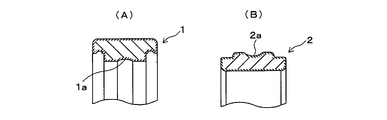
- FIG. 2 shows the outer ring 1 and the inner ring 2 of the present embodiment after the heat treatment according to the present invention.
- FIG. 2 shows the outer ring 1 and the inner ring 2 of the present embodiment after the heat treatment according to the present invention.
- FIG. 3 shows the outer ring 1 and the inner ring 2 of the comparative example after the same heat treatment.
- ferrite is formed on the surface layer portion of the entire surface.
- the end surface of the outer ring 1, the outer cylindrical surface (outer diameter surface) and the raceway groove 1a, and the end surface of the inner ring 2, the inner cylindrical surface (inner diameter surface) and the raceway groove 2a are finished by grinding.
- FIG. 4 shows a state after the outer ring and the inner ring of FIG. 3 are subjected to finish grinding to remove the ferrite layer on the surface layer portion.
- the surface layer portion in these portions.
- the ferrite layer of is removed.
- a ferrite layer remains on the surface layer of the cylindrical surfaces of the raceway grooves 1a and 2a that are not ground at the time of finishing, the seal groove for attaching the seal member 6, and the chamfered portion.
- the ferrite layer on the surface layer causes a decrease in corrosion resistance and hardness. Therefore, it is not desirable for the rolling bearing using the outer ring 1 and the inner ring 2 as shown in FIG. 4 because a portion having inferior corrosion resistance and hardness remains. Further, since the surface of the track groove 1a is finished by super-finishing, it is difficult to remove too much to obtain the state shown in FIG. 4, which leads to an increase in manufacturing cost. Therefore, it is important not to form a ferrite layer on the surface layer portion by heat treatment in order to suppress the manufacturing cost.
- the heat treatment conditions for obtaining the rolling bearing of the embodiment will be described.
- the mixture is heated to a temperature in the range of 1050 to 1120 ° C. and quenched in a heat treatment furnace having a nitrogen atmosphere with a nitrogen partial pressure of 1000 Pa or more and less than 10,000 Pa, and then -30 to -90.
- a heat treatment furnace having a nitrogen atmosphere with a nitrogen partial pressure of 1000 Pa or more and less than 10,000 Pa, and then -30 to -90.
- the nitrogen partial pressure is less than 1000 Pa, the nitrogen concentration in the surface layer portion at the time of quenching decreases and ferrite is produced.
- the partial pressure of nitrogen is 10,000 Pa or more, in the case of the martensitic stainless steel according to the present invention, nitrogen may be dissolved in the surface layer portion and the nitrogen concentration may become too high.
- the solid solution of nitrogen from the outside increases the amount of retained austenite produced after quenching and tempering, resulting in a decrease in tempering hardness.
- Nitride is produced by the addition of nitrogen, but if it is excessively added by solid solution from the outside, the effect of lowering toughness is greater than the improvement of hardness, and brittle fracture is promoted.
- the partial pressure of nitrogen is 1000 Pa or more and less than 10,000 Pa in order to prevent nitrogen from coming out from the surface layer and to avoid solid solution of nitrogen from the outside.
- quenching temperature is less than 1050 ° C., the formation of martensite by quenching (oil or water quenching) is not sufficient, and it becomes difficult to obtain hardness of HRC57 or higher.
- the quenching temperature exceeds 1120 ° C., it becomes difficult to obtain a hardness of HRC57 or higher because the former austenite crystal grains are coarsened and carbides are solid-solved. Therefore, it is desirable that the quenching temperature is 1050 to 1120 ° C.
- the present invention is not limited to the raceway rings and rolling elements of rolling bearings, and can be applied to all highly corrosion-resistant stainless steel parts used as mechanical parts such as bolts and nuts.
- Table 1 shows the component contents of examples and comparative examples of martensitic stainless steel in% by weight. Further, the desirable content range of the present invention is referred to as an effective range.
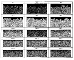
- the hardness of the sample thus obtained was measured at a depth of 20 ⁇ m from the surface of the sample. Further, the cross section of the sample was mirror-polished and then etched, and the structure of a region having a depth of 50 ⁇ m and a width of 100 ⁇ m from the surface was observed at three points with a metallurgical microscope. Then, the tissue photograph shown in FIG. 5 was image-analyzed to calculate the area ratio (area%) of ferrite in each region of 50 ⁇ m ⁇ 100 ⁇ m, and the average value thereof is shown in Table 1. The amount of retained austenite (residual ⁇ ) was determined by measuring the volume fraction (volume%) by the X-ray diffraction method with an X-ray stress measuring device (manufactured by PROTO, model number iXRD).
- a plate having a length of 50 mm, a width of 20 mm, and a thickness of 2 mm was manufactured by machining from a martensitic stainless steel bar material having the components shown in Table 1, and heat-treated under the same conditions as above.
- the sample thus obtained was subjected to a neutral salt spray test for 96 hours according to JIS Z2371, and the rating number was evaluated based on the rating number method of JIS Z2371: 2015 standard. A rating of 9.8 or higher was judged to be good and the rating was "A", and a rating of less than 9.8 was insufficient and the rating was "B".
- the above measurement results and test results are shown in Table 1 together with the material components of each sample.
- the rating number indicating corrosion resistance was 9.8 or more in all the examples, and the corrosion resistance was evaluated as "A" (good). Further, the hardness of the surface layer portion was all HRC57 or higher, which satisfied the hardness of the raceway ring of the rolling bearing specified in JIS B1511: 1993 standard.
- Comparative Example 1 since the nitrogen partial pressure at the time of quenching was 1000 Pa, ferrite was not generated in the surface layer portion, but since the C content was less than 0.35%, the hardness of the surface layer portion. Has become HRC55, which does not satisfy the JIS B1511: 1993 standard for rolling bearings. In Comparative Example 2, since the nitrogen partial pressure at the time of quenching was 2000 Pa, ferrite was not generated on the surface layer portion, but since the N content was less than 0.12%, the hardness was only HRC56. ..
- Comparative Example 5 since the partial pressure of nitrogen at the time of quenching was only 70 Pa, the amount of ferrite in the surface layer portion reached 28 area% in area ratio, and the hardness was only HRC51. In Comparative Example 6, since the nitrogen partial pressure at the time of quenching was 700 Pa, the amount of ferrite in the surface layer portion reached 19 area%, and the hardness was only HRC52.
- Comparative Example 7 Although the partial pressure of nitrogen at the time of quenching was 1000 Pa, the amount of ferrite in the surface layer portion was 6 area% and the hardness was HRC54. It is considered that this is because the content of Cr, which is a ferrite-producing element, exceeded 17% in Comparative Example 7, so that ferrite was generated in the surface layer portion after quenching, which caused a decrease in hardness.
- Comparative Example 8 Although the partial pressure of nitrogen at the time of quenching was 1000 Pa, the amount of ferrite in the surface layer portion was 4 area% and the hardness was HRC53. It is considered that this is because the content of C in Comparative Example 8 was less than 0.35%, the formation of austenite was insufficient and ferrite remained, and the content of N was less than 0.12%. ..
- Comparative Example 11 ferrite was not generated because the nitrogen partial pressure at the time of quenching was 2000 Pa, but sufficient corrosion resistance could not be obtained because the Cr content was as low as 14.73%, and the rating number was 8. The evaluation of corrosion resistance was "B”.
- Comparative Example 12 ferrite was not produced because the partial pressure of nitrogen at the time of quenching was 2000 Pa, but the Mo content was as low as 1.11%, so the rating number was 8 and the evaluation of corrosion resistance was "B". It became.
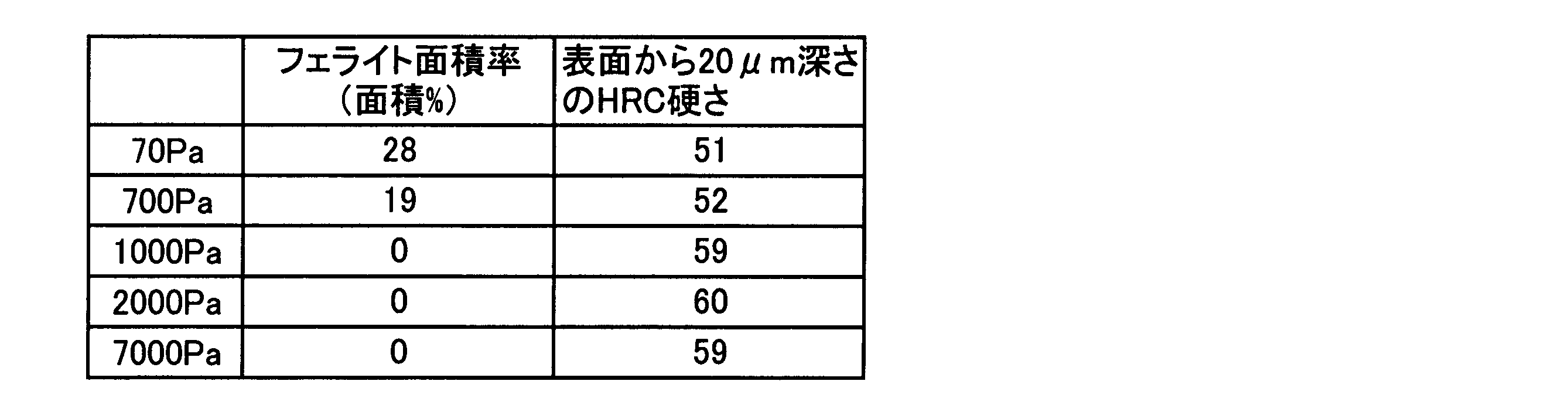
- Table 2 shows the amount of ferrite at the three locations on the surface layer of each sample in terms of ferrite area ratio (area%)
- Table 3 shows the average value of the ferrite area ratio at the three locations of each sample and the three locations at a depth of 20 ⁇ m from the surface.
- the average value of Rockwell C hardness (HRC) is shown.
- the numbers (“70” to “7000”) on the left side of the hyphen on the sample label attached to Table 2 indicate the nitrogen partial pressure (unit: Pa) at the time of quenching.
- FIG. 5 shows a tissue photograph of the surface layer portion after image processing thus obtained.
- samples 70-1 to 70-3 and samples 700-1 to 700-3 whose partial pressure of nitrogen at the time of quenching was less than 1000 Pa the upper part of the surface layer portion is shown in black in the microstructure photograph after image processing, and the sample surface. It can be clearly seen that ferrite is generated in the vicinity.
- the ferrite area ratio was calculated by the same method. As shown in Table 2, in Comparative Example 5 in which the nitrogen partial pressure at the time of quenching was 70 Pa, ferrite of 26 area% or more was generated in the surface layer portion, and ferrite of 16 to 23 area% was generated at 700 Pa. There is. When the partial pressure of nitrogen at the time of quenching becomes 1000 Pa or more, ferrite is not generated and the area ratio of ferrite is zero. Further, as shown in Table 3, when the nitrogen partial pressure at the time of quenching is 1000 Pa or more, the hardness of the portion 20 ⁇ m deep from the surface is HRC59 or more. From this, it was found that it is effective to set the nitrogen partial pressure at the time of quenching to 1000 Pa or more in order not to generate ferrite on the surface layer portion.
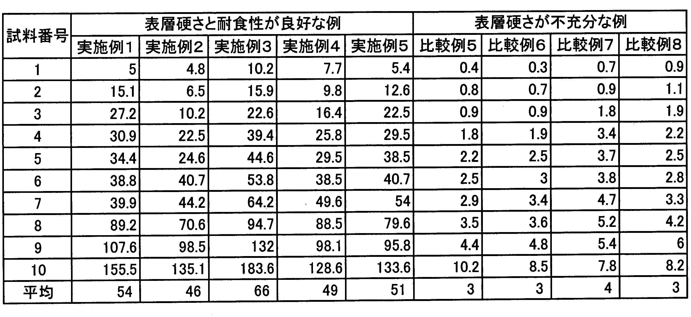
- the outer ring is attached to the holder, the inner ring is fixed to one end of the shaft, and the other end of the shaft is inserted into a pair of rolling bearings of the test device to support the shaft so that it can rotate while keeping it horizontal. did. Then, the shaft was rotated at 5400 rpm while applying a radial load of 431 N (44 kgf) in the vertical direction to the holder, and a test was conducted until the test rolling bearing attached to the holder was locked (until the shaft stopped rotating). The elapsed time from the start of the test to the locking of the test rolling bearing was used as the lock time, and the average lock time of 10 pieces was used as the evaluation index. The results are shown in Table 4.
- Example 1 a rolling bearing using the material of Example 1 is referred to as Example 1.
- Example 1 a rolling bearing using the material of Example 1
- the inner ring and the outer ring are finished with the surface hardness of the raceway surface being insufficient, in other words, with the ferrite layer left on the surface layer portion. Therefore, the surface layer portion after finishing the dimensions of the inner ring and the outer ring of the comparative example is in a state as shown in FIGS. 3 (A) and 3 (B). Further, sample numbers 1 to 10 were given to the 10 rolling bearings of each example and each comparative example.
- the rolling bearings of Examples 1 to 5 had an average lock time of 46 to 66 hours, whereas the rolling bearings of Comparative Examples 5 to 8 in which ferrite was present on the surface layer had an average lock time of 46 to 66 hours.
- the lock time was only 3-4 hours. From the above results, it was confirmed that the rolling bearing of the present invention has a long life because ferrite does not exist in the surface layer portion and the hardness is sufficient.
- the present invention can be used in the field of highly corrosion-resistant stainless steel parts such as rolling bearings, and can be suitably used in the field of highly corrosion-resistant stainless steel parts used in a particularly severe corrosion environment. Further, in the above embodiment, the case of a rolling bearing provided with a highly corrosion-resistant stainless steel component has been exemplified, but the present invention is not limited to this, and the highly corrosion-resistant stainless steel component of the present invention is an assembly used in a particularly severe corrosion environment. It is available for.
Landscapes
- Chemical & Material Sciences (AREA)
- Engineering & Computer Science (AREA)
- Mechanical Engineering (AREA)
- Materials Engineering (AREA)
- Metallurgy (AREA)
- Organic Chemistry (AREA)
- Physics & Mathematics (AREA)
- Thermal Sciences (AREA)
- Crystallography & Structural Chemistry (AREA)
- General Engineering & Computer Science (AREA)
- Manufacturing & Machinery (AREA)
- Rolling Contact Bearings (AREA)
Abstract
Description
Cは鋼部品の硬さ(耐摩耗性)を確保するのに有効な成分であるが、オーステナイト生成元素でもあるので、多量に添加すると共晶炭化物を生成し易く、割れが発生し易くなる。また、過剰な添加は耐食性も劣化させるため、良好な耐食性が確認された0.43%を上限とした。そして、熱処理後の表層部にフェライトが生成されず、HRC57以上の硬さが得られた0.35%を下限とした。
Siを過剰に含有していると靭性を著しく低下させ熱間加工性に有害になるので少ない方がよいが、製造コストを考慮して0.5%以下とした。
Mnはオーステナイト安定化元素であり、過度の添加は残留オーステナイト量を増加させるため、熱処理後の硬さを低下させ、耐食性も劣化させる他、経年による寸法変化を起こしやすい。したがって、Mnは少ない方がよいが製造コストを考慮して含有量は0.5%以下とした。
Pは、結晶粒界に析出して冷間脆性を引き起こす成分であるので、冷間脆性を避けるためにできるだけ少ないことが望ましいが、製造コストとの兼ね合いで含有量を0.04%以下とした。
Sは、耐食性を劣化させたり熱間加工性を劣化させたりするので、含有量を0.04%以下の範囲とした。
Crは、ステンレス鋼にとって、強固な不導体被膜を形成するので、高い耐食性を得るためには不可欠な元素であり、多量の添加が必要である。塩水噴霧試験結果ではCr含有量が15%を下回ると、後述するようにNの含有量が十分でも良好な耐食性が得られなかったことから15%を下限とした。しかしながら、Crはフェライトを生成させることでマルテンサイト化を阻害する要因にもなり得る。Crの含有量が17%を超える場合には、焼入れ後の表層部にフェライトが生成しており、硬度の低下を招いていたことから、17%を上限とした。
MoはNの固溶限を高めるとともに、耐食性を改善し、焼入れ性を向上させる効果を有する。このような効果を得るためには1.5%以上の添加が必要である。しかしながら、過度の添加は靭性の低下と表層付近のフェライト生成を招くので3.0%を上限とした。
Nは、マルテンサイト系ステンレス鋼の熱処理後の表面硬さと耐食性を向上させるために非常に有効な元素である。そのような効果を得るためには、Nの含有量は0.12%以上必要である。一方、加圧溶解法よりも経済的な大気溶解で材料中にブロー(気泡)の発生がなく、実用に供し得るマルテンサイト系ステンレス鋼が製鋼できた固溶限界は0.18%であったため、0.18%を上限とした。これによって製造コストを抑制した。
Bを添加するとBNが析出して強度の向上に有効で、かつ焼入れ性を高めるが、この効果を得るためには0.001%以上の添加が必要である。一方、過度の添加は靭性の低下を招くので、添加量の上限を0.005%以下とする。
Wは耐食性を向上させると共に固溶強化元素として作用して強度の向上に寄与する成分である。この作用を得るためには、0.1%以上の添加が必要である。一方、過度の添加は靭性の低下を招くので、問題のない性能が得られた0.3%を上限とした。
基地組織は、残留オーステナイトが13体積%以下、残部がマルテンサイトを含む二相混合組織であることが望ましい。軟質な残留オーステナイトを13体積%以下に抑え、残部をマルテンサイトとすることにより、HRC57以上の硬さを確保することができる。なお、基地組織とは、炭化物や窒化物および介在物を除く基地(マトリックス)の組織をいう。
切削加工で外輪と内輪を形成した後、窒素分圧1000Pa以上、かつ10000Pa未満の窒素雰囲気にした熱処理炉で1050~1120℃の範囲の温度まで加熱して焼入れし、次いで、-30~ ―90℃の範囲の温度まで冷却するサブゼロ処理を行ってから150~200℃の範囲の温度で焼戻しを行うのが望ましい。サブゼロ処理は、残留オーステナイト量を低減させて硬さを高めるのに有効だからである。
窒素分圧が1000Pa未満であると焼入れ時に表層部の窒素濃度が低下してフェライトが生成される。一方、窒素分圧が10000Pa以上であると、本発明によるマルテンサイト系ステンレス鋼の場合、表層部に窒素が固溶されて窒素濃度が高くなりすぎるおそれがある。窒素の外部からの固溶は、焼入れ焼戻し後の残留オーステナイト生成量を増大させ、焼戻し硬さの低下を招く。また、窒素添加により窒化物が生成されるが、外部からの固溶によって過剰に添加されると硬さの向上よりも靭性低下の効果が大きくなり、脆性破壊が助長される。
焼入れ温度が1050℃未満では、急冷(油または水焼入れ)によるマルテンサイトの生成が充分ではなくHRC57以上の硬さを得ることが困難となる。一方、焼入れ温度が1120℃を超えると、旧オーステナイト結晶粒の粗大化と炭化物が固溶するためHRC57以上の硬さを得ることが困難となる。よって、焼入れ温度は1050~1120℃であることが望ましい。
表1に示す成分のマルテンサイト系ステンレス鋼のバー材を機械加工することによって、外径13mm、内径11.54mm、高さ4mmの中間部品を製作し、熱処理炉を用いて表1に示す窒素分圧および焼入れ温度の条件で焼入れを行い、-30~ ―90℃の温度範囲に冷却するサブゼロ処理を行った後、150~200℃の温度範囲で焼戻しを行なってリング状の試料を得た。

以下、成分含有量が有効範囲内であって表層部にフェライトが存在しない、すなわちフェライト面積率がゼロである実施例1~3と、成分含有量が有効範囲内であるが表層部にフェライトが存在する比較例5、6とに対して行った組織観察について詳細を述べる。表2に各試料の表層部の3箇所におけるフェライト量をフェライト面積率(面積%)で示し、表3に各試料の3箇所のフェライト面積率の平均値と表面から深さ20μmにおける3箇所のロックウェルC硬さ(HRC)の平均値とを示す。なお、表2に付した試料ラベルのハイフンより左側の数字(「70」~「7000」)は焼入れ時の窒素分圧(単位:Pa)を示す。

上記の実施例1~5、比較例5~8の材料を内輪と外輪に用いて単列の深溝玉軸受を試験転がり軸受として作製した。外輪は外径13mm、内径11.54mm、幅4mmで、内輪は外径9mm、内径7mm、幅4mmとした。玉は、直径1.588mmで材質をDD400(マルテンサイトステンレス鋼、硬さHRC60)とした。保持器は、ポリアミド製の冠型保持器を使用した。
Claims (15)
- 重量比で、Cを0.35~0.43%、Siを0.5%以下、Mnを0.5%以下、Pを0.04%以下、Sを0.04%以下、Crを15~17%、Wを0.1~0.3%、Moを1.5~3.0%、Bを0.001~0.005%、Nを0.12~0.18%含有し、残部がFeおよび不可避不純物からなる高耐食マルテンサイト系ステンレス鋼からなり、全外面の表層部の基地組織が残留オーステナイトとマルテンサイトとを含む二相混合組織となっており、表面硬さがHRC57以上である高耐食ステンレス鋼部品。
- 前記二相混合組織は、13体積%以下の残留オーステナイトを含んでいる請求項1に記載の高耐食ステンレス鋼部品。
- 前記二相混合組織に分散している炭化物の個数の95%以上は、長径が10μm以下である請求項1または2に記載の高耐食ステンレス鋼部品。
- JIS Z2371規格による中性塩水噴霧試験を96時間実施した後のレイティングナンバが9.8以上である請求項1~3のいずれかに記載の高耐食ステンレス鋼部品。
- 前記高耐食ステンレス鋼部品は、窒素分圧1000Pa以上、かつ10000Pa未満の窒素雰囲気で1050~1120℃の範囲内の温度まで加熱されて焼入れされている請求項1~4のいずれかに記載の高耐食ステンレス鋼部品。
- 前記高耐食ステンレス鋼部品は、前記焼入れの後に、-30~ ―90℃の範囲内の温度まで冷却するサブゼロ処理を施されてから、150~200℃の範囲内の温度まで加熱されて焼戻しされている請求項5に記載の高耐食ステンレス鋼部品。
- 前記高耐食ステンレス鋼部品は転がり軸受の軌道輪である請求項1~6のいずれかに記載の高耐食ステンレス鋼部品。
- 内輪と外輪との間に複数の転動体を配置した転がり軸受において、少なくとも外輪または内輪が請求項7に記載の軌道輪である転がり軸受。
- 内輪と外輪との間に複数の転動体を配置した転がり軸受において、内輪および外輪が請求項7に記載の軌道輪である転がり軸受。
- 複数の単体部品を含む組立品であって、少なくとも一つの前記単体部品が請求項1~6のいずれかに記載の高耐食ステンレス鋼部品である組立品。
- 重量比で、Cを0.35~0.43%、Siを0.5%以下、Mnを0.5%以下、Pを0.04%以下、Sを0.04%以下、Crを15~17%、Wを0.1~0.3%、Moを1.5~3.0%、Bを0.001~0.005%、Nを0.12~0.18%含有し、残部がFeおよび不可避不純物からなる高耐食マルテンサイト系ステンレス鋼からなる中間部品を準備するステップと、
前記中間部品を窒素分圧1000Pa以上、かつ10000Pa未満の窒素雰囲気において、1050~1120℃の範囲内の温度まで加熱して焼入れするステップと、
を含む高耐食ステンレス鋼部品の熱処理方法。 - 前記焼入れの後に、前記中間部品を-30~ ―90℃の範囲内の温度まで冷却するサブゼロ処理のステップと、
前記サブゼロ処理後に150~200℃の範囲内の温度まで加熱して焼戻すステップと、
を含む請求項11に記載の高耐食ステンレス鋼部品の熱処理方法。 - 前記ステンレス鋼部品が、転がり軸受の軌道輪である請求項11または12に記載の高耐食ステンレス鋼部品の熱処理方法。
- 請求項11~13のいずれかに記載の高耐食ステンレス鋼部品の熱処理方法を含む高耐食ステンレス鋼部品の製造方法。
- 内輪と外輪との間に複数の転動体を配置した転がり軸受の製造方法であって、少なくとも内輪または外輪が請求項14に記載の高耐食ステンレス鋼部品の製造方法で製造される転がり軸受の製造方法。
Priority Applications (6)
| Application Number | Priority Date | Filing Date | Title |
|---|---|---|---|
| CN202080105432.2A CN116194600B (zh) | 2020-09-25 | 2020-09-25 | 高耐蚀不锈钢部件及其制造方法、不锈钢部件的热处理方法以及滚动轴承及其制造方法 |
| KR1020237011790A KR20230075465A (ko) | 2020-09-25 | 2020-09-25 | 고내식 스테인리스강 부품 및 그 제조 방법, 스테인리스강 부품의 열처리 방법, 그리고 구름 베어링 및 그 제조 방법 |
| DE112020007636.9T DE112020007636T5 (de) | 2020-09-25 | 2020-09-25 | Hochkorrosionsbeständige edelstahlkomponente und verfahren zur herstellung derselben, verfahren zur wärmebehandlung einer edelstahlkomponente und wälzlager und verfahren zur herstellung desselben |
| JP2022551526A JP7627701B2 (ja) | 2020-09-25 | 2020-09-25 | 高耐食ステンレス鋼部品およびその製造方法、ステンレス鋼部品の熱処理方法、ならびに転がり軸受およびその製造方法 |
| US18/044,098 US20230323499A1 (en) | 2020-09-25 | 2020-09-25 | Highly corrosion-resistant stainless steel member and method for manufacturing same, heat treatment method for stainless steel member, and rolling bearing and method for manufacturing same |
| PCT/JP2020/036329 WO2022064643A1 (ja) | 2020-09-25 | 2020-09-25 | 高耐食ステンレス鋼部品およびその製造方法、ステンレス鋼部品の熱処理方法、ならびに転がり軸受およびその製造方法 |
Applications Claiming Priority (1)
| Application Number | Priority Date | Filing Date | Title |
|---|---|---|---|
| PCT/JP2020/036329 WO2022064643A1 (ja) | 2020-09-25 | 2020-09-25 | 高耐食ステンレス鋼部品およびその製造方法、ステンレス鋼部品の熱処理方法、ならびに転がり軸受およびその製造方法 |
Publications (1)
| Publication Number | Publication Date |
|---|---|
| WO2022064643A1 true WO2022064643A1 (ja) | 2022-03-31 |
Family
ID=80846355
Family Applications (1)
| Application Number | Title | Priority Date | Filing Date |
|---|---|---|---|
| PCT/JP2020/036329 Ceased WO2022064643A1 (ja) | 2020-09-25 | 2020-09-25 | 高耐食ステンレス鋼部品およびその製造方法、ステンレス鋼部品の熱処理方法、ならびに転がり軸受およびその製造方法 |
Country Status (6)
| Country | Link |
|---|---|
| US (1) | US20230323499A1 (ja) |
| JP (1) | JP7627701B2 (ja) |
| KR (1) | KR20230075465A (ja) |
| CN (1) | CN116194600B (ja) |
| DE (1) | DE112020007636T5 (ja) |
| WO (1) | WO2022064643A1 (ja) |
Cited By (1)
| Publication number | Priority date | Publication date | Assignee | Title |
|---|---|---|---|---|
| TWI893746B (zh) * | 2024-04-03 | 2025-08-11 | 中國鋼鐵股份有限公司 | 鋼材及其熱處理方法 |
Citations (7)
| Publication number | Priority date | Publication date | Assignee | Title |
|---|---|---|---|---|
| JPH1036945A (ja) * | 1996-07-19 | 1998-02-10 | Nippon Steel Corp | ねじ込み性に優れた高耐銹性マルテンサイト系ステンレス製ドリリングタッピンねじ及びその焼入方法 |
| JP2000345304A (ja) * | 1999-06-09 | 2000-12-12 | Fukui Byora Co Ltd | 打ち込みリベット及びその製造方法 |
| JP2010077525A (ja) * | 2008-09-01 | 2010-04-08 | Minebea Co Ltd | マルテンサイト系ステンレス鋼および転がり軸受 |
| JP2010265487A (ja) * | 2009-05-12 | 2010-11-25 | Minebea Co Ltd | マルテンサイト系ステンレス鋼および転がり軸受 |
| WO2017141928A1 (ja) * | 2016-02-19 | 2017-08-24 | 株式会社ジェイテクト | 転がり摺動部材とこれを利用した転がり軸受、及び転がり摺動部材の製造方法 |
| WO2018008674A1 (ja) * | 2016-07-06 | 2018-01-11 | 日立金属株式会社 | 燃料噴射部材用マルテンサイト系ステンレス鋼及びそれを用いた燃料噴射部材 |
| JP2020180313A (ja) * | 2019-04-23 | 2020-11-05 | 大同特殊鋼株式会社 | 高硬度部材及びその製造方法 |
Family Cites Families (4)
| Publication number | Priority date | Publication date | Assignee | Title |
|---|---|---|---|---|
| JP3390779B2 (ja) * | 1996-05-13 | 2003-03-31 | 山陽特殊製鋼株式会社 | 錆発生環境下における耐摩耗性と耐剥離性、耐チャタマーク性に優れた高靱性冷間ロール |
| JP4633661B2 (ja) * | 2006-03-20 | 2011-02-16 | 日産自動車株式会社 | セルフピアスリベットの製造方法 |
| JP5370813B2 (ja) * | 2008-12-09 | 2013-12-18 | ミネベア株式会社 | マルテンサイト系ステンレス鋼 |
| KR101977502B1 (ko) * | 2017-12-07 | 2019-05-10 | 주식회사 포스코 | 변형능 및 냉간압조 후 인장강도가 우수한 냉간압조용 선재 및 그 제조방법 |
-
2020
- 2020-09-25 CN CN202080105432.2A patent/CN116194600B/zh active Active
- 2020-09-25 WO PCT/JP2020/036329 patent/WO2022064643A1/ja not_active Ceased
- 2020-09-25 KR KR1020237011790A patent/KR20230075465A/ko not_active Ceased
- 2020-09-25 US US18/044,098 patent/US20230323499A1/en active Pending
- 2020-09-25 DE DE112020007636.9T patent/DE112020007636T5/de active Pending
- 2020-09-25 JP JP2022551526A patent/JP7627701B2/ja active Active
Patent Citations (7)
| Publication number | Priority date | Publication date | Assignee | Title |
|---|---|---|---|---|
| JPH1036945A (ja) * | 1996-07-19 | 1998-02-10 | Nippon Steel Corp | ねじ込み性に優れた高耐銹性マルテンサイト系ステンレス製ドリリングタッピンねじ及びその焼入方法 |
| JP2000345304A (ja) * | 1999-06-09 | 2000-12-12 | Fukui Byora Co Ltd | 打ち込みリベット及びその製造方法 |
| JP2010077525A (ja) * | 2008-09-01 | 2010-04-08 | Minebea Co Ltd | マルテンサイト系ステンレス鋼および転がり軸受 |
| JP2010265487A (ja) * | 2009-05-12 | 2010-11-25 | Minebea Co Ltd | マルテンサイト系ステンレス鋼および転がり軸受 |
| WO2017141928A1 (ja) * | 2016-02-19 | 2017-08-24 | 株式会社ジェイテクト | 転がり摺動部材とこれを利用した転がり軸受、及び転がり摺動部材の製造方法 |
| WO2018008674A1 (ja) * | 2016-07-06 | 2018-01-11 | 日立金属株式会社 | 燃料噴射部材用マルテンサイト系ステンレス鋼及びそれを用いた燃料噴射部材 |
| JP2020180313A (ja) * | 2019-04-23 | 2020-11-05 | 大同特殊鋼株式会社 | 高硬度部材及びその製造方法 |
Cited By (1)
| Publication number | Priority date | Publication date | Assignee | Title |
|---|---|---|---|---|
| TWI893746B (zh) * | 2024-04-03 | 2025-08-11 | 中國鋼鐵股份有限公司 | 鋼材及其熱處理方法 |
Also Published As
| Publication number | Publication date |
|---|---|
| JPWO2022064643A1 (ja) | 2022-03-31 |
| CN116194600B (zh) | 2026-03-13 |
| DE112020007636T5 (de) | 2023-08-10 |
| US20230323499A1 (en) | 2023-10-12 |
| CN116194600A (zh) | 2023-05-30 |
| JP7627701B2 (ja) | 2025-02-06 |
| KR20230075465A (ko) | 2023-05-31 |
Similar Documents
| Publication | Publication Date | Title |
|---|---|---|
| CN106574338B (zh) | 碳氮共渗轴承部件 | |
| KR101332933B1 (ko) | 표면 경화용 기계 구조용 강 및 기계 구조용 부품 | |
| JPH09287058A (ja) | 転がり軸受 | |
| US6808571B2 (en) | Heat resistant carburized rolling bearing component and manufacturing method thereof | |
| JP2002115030A (ja) | 工作機械主軸用転がり軸受 | |
| US20160273587A1 (en) | Bearing steel | |
| JP2021154329A (ja) | 鍛造用材料、鍛造部材および鍛造部材の製造方法 | |
| JP5728844B2 (ja) | 転がり軸受 | |
| JP4998054B2 (ja) | 転がり軸受 | |
| JP2000226641A (ja) | 転動装置 | |
| JP2010265487A (ja) | マルテンサイト系ステンレス鋼および転がり軸受 | |
| JP7627701B2 (ja) | 高耐食ステンレス鋼部品およびその製造方法、ステンレス鋼部品の熱処理方法、ならびに転がり軸受およびその製造方法 | |
| JP2000204445A (ja) | 高温用転がり軸受部品 | |
| JP2010031307A (ja) | ころ軸受 | |
| US11136639B2 (en) | Bearing steel and manufacturing method therefor | |
| JP5668283B2 (ja) | 転がり摺動部材の製造方法 | |
| WO2014019670A1 (en) | Low temperature heat treatment for steel alloy | |
| JP7422527B2 (ja) | 転動部品及びその製造方法 | |
| JP5119717B2 (ja) | 転がり軸受構成部材の製造方法および転がり軸受 | |
| JPH0611899B2 (ja) | 高クロム系軸受鋼 | |
| JP2000204444A (ja) | 高温用転がり軸受部品 | |
| JP7212100B2 (ja) | 転がり軸受 | |
| JP2010249215A (ja) | 水素雰囲気用転がり軸受 | |
| JP2025031089A (ja) | 転動部材 | |
| JP2025031088A (ja) | 転動部材 |
Legal Events
| Date | Code | Title | Description |
|---|---|---|---|
| 121 | Ep: the epo has been informed by wipo that ep was designated in this application |
Ref document number: 20955237 Country of ref document: EP Kind code of ref document: A1 |
|
| ENP | Entry into the national phase |
Ref document number: 2022551526 Country of ref document: JP Kind code of ref document: A |
|
| ENP | Entry into the national phase |
Ref document number: 20237011790 Country of ref document: KR Kind code of ref document: A |
|
| 122 | Ep: pct application non-entry in european phase |
Ref document number: 20955237 Country of ref document: EP Kind code of ref document: A1 |