WO2022059100A1 - 制御装置、換気システム、空調装置、換気制御方法及びプログラム - Google Patents
制御装置、換気システム、空調装置、換気制御方法及びプログラム Download PDFInfo
- Publication number
- WO2022059100A1 WO2022059100A1 PCT/JP2020/035109 JP2020035109W WO2022059100A1 WO 2022059100 A1 WO2022059100 A1 WO 2022059100A1 JP 2020035109 W JP2020035109 W JP 2020035109W WO 2022059100 A1 WO2022059100 A1 WO 2022059100A1
- Authority
- WO
- WIPO (PCT)
- Prior art keywords
- ventilation
- volume
- air
- control device
- ventilation volume
- Prior art date
- Legal status (The legal status is an assumption and is not a legal conclusion. Google has not performed a legal analysis and makes no representation as to the accuracy of the status listed.)
- Ceased
Links
Images


Classifications
-
- F—MECHANICAL ENGINEERING; LIGHTING; HEATING; WEAPONS; BLASTING
- F24—HEATING; RANGES; VENTILATING
- F24F—AIR-CONDITIONING; AIR-HUMIDIFICATION; VENTILATION; USE OF AIR CURRENTS FOR SCREENING
- F24F11/00—Control or safety arrangements
- F24F11/0001—Control or safety arrangements for ventilation
-
- F—MECHANICAL ENGINEERING; LIGHTING; HEATING; WEAPONS; BLASTING
- F24—HEATING; RANGES; VENTILATING
- F24F—AIR-CONDITIONING; AIR-HUMIDIFICATION; VENTILATION; USE OF AIR CURRENTS FOR SCREENING
- F24F11/00—Control or safety arrangements
- F24F11/62—Control or safety arrangements characterised by the type of control or by internal processing, e.g. using fuzzy logic, adaptive control or estimation of values
- F24F11/63—Electronic processing
-
- F—MECHANICAL ENGINEERING; LIGHTING; HEATING; WEAPONS; BLASTING
- F24—HEATING; RANGES; VENTILATING
- F24F—AIR-CONDITIONING; AIR-HUMIDIFICATION; VENTILATION; USE OF AIR CURRENTS FOR SCREENING
- F24F11/00—Control or safety arrangements
- F24F11/30—Control or safety arrangements for purposes related to the operation of the system, e.g. for safety or monitoring
- F24F11/41—Defrosting; Preventing freezing
- F24F11/42—Defrosting; Preventing freezing of outdoor units
-
- F—MECHANICAL ENGINEERING; LIGHTING; HEATING; WEAPONS; BLASTING
- F24—HEATING; RANGES; VENTILATING
- F24F—AIR-CONDITIONING; AIR-HUMIDIFICATION; VENTILATION; USE OF AIR CURRENTS FOR SCREENING
- F24F11/00—Control or safety arrangements
- F24F11/62—Control or safety arrangements characterised by the type of control or by internal processing, e.g. using fuzzy logic, adaptive control or estimation of values
- F24F11/63—Electronic processing
- F24F11/65—Electronic processing for selecting an operating mode
-
- F—MECHANICAL ENGINEERING; LIGHTING; HEATING; WEAPONS; BLASTING
- F24—HEATING; RANGES; VENTILATING
- F24F—AIR-CONDITIONING; AIR-HUMIDIFICATION; VENTILATION; USE OF AIR CURRENTS FOR SCREENING
- F24F11/00—Control or safety arrangements
- F24F11/70—Control systems characterised by their outputs; Constructional details thereof
- F24F11/72—Control systems characterised by their outputs; Constructional details thereof for controlling the supply of treated air, e.g. its pressure
- F24F11/74—Control systems characterised by their outputs; Constructional details thereof for controlling the supply of treated air, e.g. its pressure for controlling air flow rate or air velocity
- F24F11/77—Control systems characterised by their outputs; Constructional details thereof for controlling the supply of treated air, e.g. its pressure for controlling air flow rate or air velocity by controlling the speed of ventilators
-
- F—MECHANICAL ENGINEERING; LIGHTING; HEATING; WEAPONS; BLASTING
- F24—HEATING; RANGES; VENTILATING
- F24F—AIR-CONDITIONING; AIR-HUMIDIFICATION; VENTILATION; USE OF AIR CURRENTS FOR SCREENING
- F24F7/00—Ventilation
- F24F2007/004—Natural ventilation using convection
-
- F—MECHANICAL ENGINEERING; LIGHTING; HEATING; WEAPONS; BLASTING
- F24—HEATING; RANGES; VENTILATING
- F24F—AIR-CONDITIONING; AIR-HUMIDIFICATION; VENTILATION; USE OF AIR CURRENTS FOR SCREENING
- F24F2120/00—Control inputs relating to users or occupants
-
- F—MECHANICAL ENGINEERING; LIGHTING; HEATING; WEAPONS; BLASTING
- F24—HEATING; RANGES; VENTILATING
- F24F—AIR-CONDITIONING; AIR-HUMIDIFICATION; VENTILATION; USE OF AIR CURRENTS FOR SCREENING
- F24F2120/00—Control inputs relating to users or occupants
- F24F2120/10—Occupancy
-
- F—MECHANICAL ENGINEERING; LIGHTING; HEATING; WEAPONS; BLASTING
- F24—HEATING; RANGES; VENTILATING
- F24F—AIR-CONDITIONING; AIR-HUMIDIFICATION; VENTILATION; USE OF AIR CURRENTS FOR SCREENING
- F24F2221/00—Details or features not otherwise provided for
- F24F2221/54—Heating and cooling, simultaneously or alternatively
-
- Y—GENERAL TAGGING OF NEW TECHNOLOGICAL DEVELOPMENTS; GENERAL TAGGING OF CROSS-SECTIONAL TECHNOLOGIES SPANNING OVER SEVERAL SECTIONS OF THE IPC; TECHNICAL SUBJECTS COVERED BY FORMER USPC CROSS-REFERENCE ART COLLECTIONS [XRACs] AND DIGESTS
- Y02—TECHNOLOGIES OR APPLICATIONS FOR MITIGATION OR ADAPTATION AGAINST CLIMATE CHANGE
- Y02B—CLIMATE CHANGE MITIGATION TECHNOLOGIES RELATED TO BUILDINGS, e.g. HOUSING, HOUSE APPLIANCES OR RELATED END-USER APPLICATIONS
- Y02B30/00—Energy efficient heating, ventilation or air conditioning [HVAC]
- Y02B30/70—Efficient control or regulation technologies, e.g. for control of refrigerant flow, motor or heating
Definitions
- This disclosure relates to control devices, ventilation systems, air conditioners, ventilation control methods and programs.
- the ventilation frequency is the number of times that the air in all the rooms in the house is replaced per hour.
- a ventilation rate of 0.5 times / h indicates that a volume of air corresponding to 50% of the volume of all living rooms (floor area x ceiling height) is replaced in one hour.
- ventilation can be broadly divided into ventilation using mechanical ventilation equipment such as ventilation fans and air conditioners (so-called mechanical ventilation) and ventilation without mechanical ventilation equipment, that is, gaps between air supply / exhaust ports, windows, doors, etc.
- mechanical ventilation ventilation fans and air conditioners
- ventilation without mechanical ventilation equipment that is, gaps between air supply / exhaust ports, windows, doors, etc.
- natural ventilation There are two types of ventilation through natural ventilation (so-called natural ventilation).
- the ventilation volume due to natural ventilation tends to increase as the difference between the room temperature and the outside air temperature increases.
- the present disclosure has been made to solve the above-mentioned problems, and provides a control device and the like capable of preventing a decrease in comfort during air conditioning while ensuring a specified ventilation frequency in ventilation in a building.
- the purpose is to do.
- the control device is It is a control device that controls the ventilation means that ventilates the building.
- the ventilation means When the heating operation is not performed by the air-conditioning means for air-conditioning the inside of the building, the ventilation means is controlled to operate at the first ventilation volume, and when the heating operation is performed by the air-conditioning means, the first ventilation means is used.
- a ventilation control means for controlling the ventilation means so as to operate with a second ventilation volume smaller than the ventilation volume is provided.
- a block diagram showing a hardware configuration of a control device according to the first embodiment The figure for demonstrating the outline of the air conditioner in Embodiment 1.
- a block diagram showing a hardware configuration of an air conditioner according to the first embodiment A block diagram showing a hardware configuration of an operation terminal according to the first embodiment.
- the figure which shows the display example of the notification screen in Embodiment 1. A flowchart showing the procedure of the ventilation control process in the first embodiment.
- the figure which shows the display example of the notification screen in Embodiment 3. A block diagram showing a functional configuration of a control device and an operation terminal according to the fourth embodiment.
- FIG. 5 The figure which shows the display example of the notification screen in Embodiment 4.
- Block diagram showing the hardware configuration of the server in the fifth embodiment A block diagram showing a functional configuration of a server and an operation terminal in the fifth embodiment.
- FIG. 1 is a diagram showing an overall configuration of a ventilation system 1 according to the first embodiment of the present disclosure.
- the ventilation system 1 is a system that ventilates the house H for 24 hours, and includes a control device 2, a ventilation device 3, an air conditioning device 4, and an operation terminal 5.
- the control device 2 is an example of the control device according to the present disclosure.
- the control device 2 is installed at an appropriate place in the house H and communicates with the ventilation device 3, the air conditioner 4, and the operation terminal 5 via the home network N1 such as a LAN (Local Area Network) constructed in the house H. It is a device that can be connected as possible and controls the operation of the ventilation device 3 based on the operating state of the air conditioner 4.
- the home network N1 such as a LAN (Local Area Network) constructed in the house H. It is a device that can be connected as possible and controls the operation of the ventilation device 3 based on the operating state of the air conditioner 4.
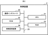
- the control device 2 includes a communication interface 20, a CPU (Central Processing Unit) 21, a ROM (ReadOnlyMemory) 22, a RAM (RandomAccessMemory) 23, and an auxiliary storage device 24. Be prepared. These components are connected to each other via the bus 25.
- a CPU Central Processing Unit
- ROM ReadOnlyMemory
- RAM RandomAccessMemory
- the communication interface 20 is hardware for communicating with the ventilation device 3, the air conditioner 4, and the operation terminal 5 via the home network N1.
- the CPU 21 comprehensively controls the control device 2. The details of the function of the control device 2 realized by the CPU 21 will be described later.
- the ROM 22 stores a plurality of firmwares and data used when executing these firmwares.
- the RAM 23 is used as a work area of the CPU 21.
- the auxiliary storage device 24 is composed of a readable / writable non-volatile semiconductor memory, an HDD (Hard Disk Drive), or the like.
- the non-volatile semiconductor memory that can be read and written is, for example, EEPROM (Electrically Erasable Programmable Read-Only Memory), flash memory, or the like.
- the auxiliary storage device 24 stores various programs including a program for realizing 24-hour ventilation of the house H (hereinafter referred to as a 24-hour ventilation program) and data used when executing these programs. Will be done.
- the above 24-hour ventilation program (including the update program for updating the 24-hour ventilation program) is downloaded from the server installed and operated by the company providing the ventilation system 1, the affiliated company, etc. to the control device 2. can do.
- the 24-hour ventilation program (including updates) includes CD-ROM (Compact Disc Read Only Memory), DVD (Digital Versatile Disc), magneto-optical disc (Magneto-Optical Disc), and USB (Universal Serial Bus) memory.
- CD-ROM Compact Disc Read Only Memory
- DVD Digital Versatile Disc
- magneto-optical disc Magnetic-Optical Disc
- USB Universal Serial Bus
- Memory card Memory card, HDD, SSD (Solid State Drive) and other computer-readable recording media can be stored and distributed.
- the ventilation device 3 is an example of the ventilation means according to the present disclosure.
- the ventilation device 3 is a device that ventilates the inside of the house H by a type 3 ventilation method.
- the ventilation device 3 is a ventilation fan including a control circuit, a propeller fan, a motor, a motor drive circuit, a shutter, and a dedicated remote controller, and is installed on a wall or ceiling of a bathroom, for example.
- the ventilation device 3 further has a communication interface for communicating with the control device 2 via the home network N1.
- the ventilation device 3 may be configured to connect to the home network N1 via an external communication adapter and communicate with the control device 2.
- the ventilator 3 has an effective ventilation volume capable of ensuring a ventilation frequency of 0.5 times / h or more.
- the operation of the ventilation device 3 is controlled by the control device 2. That is, the operation of the ventilation device 3 is started or stopped, or the ventilation volume is changed according to the control command from the control device 2. Further, the user can directly operate the dedicated remote controller of the ventilation device 3 to instruct the ventilation device 3 to start and stop the operation and change the ventilation volume.
- the air conditioner 4 is an example of the air conditioner means according to the present disclosure.
- the air conditioner 4 is a heat pump type air conditioner using HFC (hydrofluorocarbon) such as R32 and a natural refrigerant such as CO 2 as a refrigerant, and is a household air conditioner for indoor air conditioning in a house H.
- the air conditioner 4 is equipped with a steam compression type refrigeration cycle, and operates by obtaining electric power from a commercial power source, a power generation facility, a power storage facility, etc. (not shown).
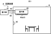
- the air conditioner 4 includes an indoor unit 40 installed in a room R such as an LDK (living / dining / kitchen), an outdoor unit 41 installed outdoors, and a remote controller 42.
- the indoor unit 40 and the outdoor unit 41 are connected to each other via a refrigerant pipe 43 for circulating the refrigerant and a communication line 44.
- the indoor unit 40 includes a control circuit 400, a heat exchanger 401, a fan 402, a temperature sensor 403, and a thermal image sensor 404.
- the control circuit 400 comprehensively controls the air conditioner 4.
- the control circuit 400 includes a CPU, a ROM, a RAM, a first communication interface, a second communication interface, a third communication interface, and an auxiliary storage device.
- the first communication interface is hardware for communicating with the outdoor unit 41 via the communication line 44
- the second communication interface is hardware for communicating with the remote controller 42 by wire or wirelessly.
- the communication interface is hardware for communicating with the control device 2 via the home network N1.
- the indoor unit 40 may be configured to connect to the home network N1 via an external communication adapter and communicate with the control device 2.
- the auxiliary storage device is configured to include a readable / writable non-volatile semiconductor memory, and stores a program for controlling the operation of the air conditioner 4 and data used when executing such a program.
- the non-volatile semiconductor memory that can be read and written is, for example, EEPROM, flash memory, or the like.
- the heat exchanger 401 exchanges heat between the indoor air sucked by the fan 402 (that is, the air in the room R) and the refrigerant from the outdoor unit 41.
- the heat exchanger 401 functions as an evaporator during the cooling operation and as a condenser during the heating operation.
- the fan 402 is, for example, a propeller fan, and sucks air in the room from a suction port (not shown) provided in the indoor unit 40, and sends out the air heat exchanged by the heat exchanger 401 into the room from an outlet (see FIG. 3). ..
- the rotation speed of the fan 402, that is, the amount of air blown by the fan 402 is adjusted according to a command from the control circuit 400.
- the temperature sensor 403 is a sensor such as a thermistor, a thermocouple, or a resistance temperature detector, measures the temperature of the air sucked by the fan 402 (that is, room temperature), and outputs a signal indicating the measured room temperature to the control circuit 400. do.
- the thermal image sensor 404 is an infrared thermography, acquires indoor thermal image data, and outputs the acquired thermal image data to the control circuit 400.
- the control circuit 400 can acquire the position and surface temperature of the object to be detected such as a floor, a wall, a window, furniture, and a person by analyzing the thermal image data acquired by the thermal image sensor 404.
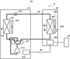
- the outdoor unit 41 includes a control circuit 410, a compressor 411, a four-way valve 412, a heat exchanger 413, a fan 414, an expansion valve 415, and a temperature sensor 416.
- the compressor 411, the four-way valve 412, the heat exchanger 413 and the expansion valve 415 in the outdoor unit 41 and the heat exchanger 401 of the indoor unit 40 are connected in an annular shape by the refrigerant pipe 43. This forms a refrigeration cycle.
- the control circuit 410 controls each part of the outdoor unit 41 according to a command from the indoor unit 40.
- the control circuit 410 includes a CPU, a ROM, a RAM, a communication interface for communicating with the indoor unit 40 (more specifically, the control circuit 400) via the communication line 44, and an auxiliary storage. Equipped with a device.
- the auxiliary storage device is configured to include a readable / writable non-volatile semiconductor memory, and stores a program for controlling the operation of the outdoor unit 41 and data used when the program is executed.
- the non-volatile semiconductor memory that can be read and written is, for example, EEPROM, flash memory, or the like.
- the compressor 411 compresses the refrigerant. Specifically, the compressor 411 compresses the low-temperature and low-pressure refrigerant, and discharges the high-pressure and high-temperature refrigerant to the four-way valve 412.
- the compressor 411 includes an inverter circuit capable of changing the operating capacity according to the drive frequency.
- the operating capacity is the amount that the compressor 411 sends out the refrigerant per unit.
- the compressor 411 changes the operating capacity according to a command from the control circuit 410.
- the four-way valve 412 is a valve for switching the circulation direction of the refrigerant.
- the four-way valve 412 is switched as shown by the solid line in FIG. 4 during the heating operation.
- the refrigerant circulates in the order of the compressor 411, the four-way valve 412, the heat exchanger 401, the expansion valve 415, and the heat exchanger 413.
- the four-way valve 412 is switched as shown by the wavy line in FIG.
- the refrigerant circulates in the order of the compressor 411, the four-way valve 412, the heat exchanger 413, the expansion valve 415, and the heat exchanger 401.
- the heat exchanger 413 exchanges heat between the outdoor air (that is, the outside air) sucked by the fan 414 and the refrigerant.
- the heat exchanger 413 functions as a condenser during the cooling operation and as an evaporator during the heating operation.
- the fan 414 is, for example, a propeller fan, which sucks in outside air and sends out the air heat exchanged by the heat exchanger 413 to the outside.
- the expansion valve 415 is installed between the heat exchanger 413 and the heat exchanger 401, and decompresses and expands the refrigerant flowing through the refrigerant pipe 43.
- the expansion valve 415 is, for example, an electronic expansion valve whose throttle opening degree can be adjusted by a stepping motor (not shown).
- the expansion valve 415 adjusts the pressure of the refrigerant by changing the opening degree according to a command from the control circuit 410.
- the temperature sensor 416 is a sensor such as a thermistor, a thermocouple, or a resistance temperature detector, measures the temperature of the outside air sucked by the fan 414 (that is, the outside air temperature), and outputs a signal indicating the measured outside air temperature to the control circuit 410. Output to.
- the remote controller 42 is a remote controller that is embedded in the wall of the room R or installed in a manner hung on the wall to receive an operation related to air conditioning from a user in the room R.
- the remote controller 42 is connected to the control circuit 400 of the indoor unit 40 by wire or wireless communication.
- the user can instruct the air conditioner 4 to start and stop the operation in which one or two or more of the plurality of types of operations are combined, and the set temperature. , Wind speed, wind direction, etc. can be instructed.
- the type of operation of the air conditioner 4 includes, for example, cooling operation, heating operation, ventilation operation, dehumidification operation, humidification operation, air purification operation, high temperature air operation, powerful operation, maintenance operation, and the like.
- the maintenance operation refers to an operation for heating the heat exchanger 401 to evaporate water droplets adhering to the heat exchanger 401 of the indoor unit 40 in a cooling operation, a dehumidifying operation, or the like.
- the operation terminal 5 is an electronic device that serves as an interface with the user in the ventilation system 1.
- the operation terminal 5 is a smart device such as a smartphone or a tablet terminal, a PC (Personal Computer), a television, or the like.
- the operation terminal 5 includes a display 50, an operation reception unit 51, a communication interface 52, a CPU 53, a ROM 54, a RAM 55, and an auxiliary storage device 56. These components are connected to each other via a bus 57.
- the display 50 includes a display device such as a liquid crystal display and an organic EL (ElectroLuminescence) display.
- the display 50 displays various screens and the like according to user operations under the control of the CPU 53.
- the operation receiving unit 51 is configured to include one or more input devices such as a push button, a touch panel, and a touch pad, receives an operation input from a user, and sends a signal related to the received operation to the CPU 53.
- input devices such as a push button, a touch panel, and a touch pad
- the communication interface 52 is hardware for communicating with the control device 2 via the home network N1.
- the CPU 53 comprehensively controls the operation terminal 5. Details of the functions of the operation terminal 5 realized by the CPU 53 will be described later.
- the ROM 54 stores a plurality of firmwares and data used when executing these firmwares.
- the RAM 55 is used as a work area of the CPU 53.
- the auxiliary storage device 56 is composed of a readable / writable non-volatile semiconductor memory, an HDD, or the like.
- the non-volatile semiconductor memory that can be read and written is, for example, EEPROM, flash memory, or the like.
- the auxiliary storage device 56 stores various programs including an application program (hereinafter referred to as a ventilation application) related to the operation of the ventilation device 3 and data used when executing these programs.
- a ventilation application an application program related to the operation of the ventilation device 3 and data used when executing these programs.
- the ventilation application (including the update program for updating the ventilation application) is downloaded to the operation terminal 5 from a server installed and operated by a company that provides the ventilation system 1, an affiliated company, or another program distribution server. be able to. Ventilation apps (including updates) can also be stored and distributed on computer-readable recording media such as CD-ROMs, DVDs, magneto-optical disks, USB memories, memory cards, HDDs, and SSDs. ..
- the user can make various settings regarding the ventilation device 3 for the control device 2, and can confirm the notification from the control device 2 regarding the operation of the ventilation device 3. .
- the user can set whether or not to perform 24-hour ventilation via a setting screen (not shown) displayed on the display 50 of the operation terminal 5, and the ventilation device 3 can be set. It is possible to set whether or not to automatically adjust the ventilation volume of. The details of the automatic adjustment of the ventilation volume and the details of the notification from the control device 2 will be described later.
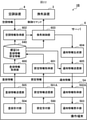
- FIG. 7 is a block diagram showing a functional configuration of the control device 2 and the operation terminal 5.
- the control device 2 includes a setting information acquisition unit 200, an air conditioning information acquisition unit 201, a ventilation control unit 202, a notification information generation unit 203, and a notification information transmission unit 204.
- These functional units of the control device 2 are realized by the CPU 21 executing the above-mentioned 24-hour ventilation program stored in the auxiliary storage device 24.
- the operation terminal 5 includes a setting reception unit 500, a setting information transmission unit 501, a notification information acquisition unit 502, and a notification information display unit 503. These functional units of the operation terminal 5 are realized by the CPU 53 executing the above-mentioned ventilation application stored in the auxiliary storage device 56.
- the setting reception unit 500 receives a setting regarding 24-hour ventilation from the user. As described above, the setting reception unit 500 displays a setting screen (not shown), and the user can set, for example, whether to perform 24-hour ventilation and whether to automatically adjust the ventilation volume of the ventilation device 3. Accept (see Figure 6).
- the setting information transmitting unit 501 transmits information indicating the user's settings (hereinafter referred to as setting information) received by the setting receiving unit 500 to the control device 2.
- the setting information acquisition unit 200 of the control device 2 receives and acquires the setting information transmitted from the operation terminal 5.
- the setting information acquisition unit 200 stores the acquired setting information in the setting information table 240.
- the setting information table 240 is a data table and is stored in the auxiliary storage device 24.
- the air conditioning information acquisition unit 201 periodically acquires air conditioning information from the air conditioning device 4. For example, the air conditioning information acquisition unit 201 acquires air conditioning information from the air conditioning device 4 at a cycle of 1 minute. Specifically, the air-conditioning information acquisition unit 201 periodically transmits a command for requesting air-conditioning information to the air-conditioning device 4 (hereinafter, referred to as an air-conditioning information request command). When the air-conditioning device 4 receives the air-conditioning information request command, it generates air-conditioning information which is information related to the current air-conditioning operation, and transmits the generated air-conditioning information to the control device 2.
- Information indicating the above, information indicating the operation mode, room temperature data, and outside temperature data are included.
- the room temperature data is data indicating the room temperature measured by the temperature sensor 403 included in the indoor unit 40
- the outside air temperature data is data indicating the outside air temperature measured by the temperature sensor 416 included in the outdoor unit 41.
- the air conditioning information acquisition unit 201 receives and acquires the air conditioning information sent from the air conditioning device 4 after transmitting the air conditioning information request command.
- the air conditioning information acquisition unit 201 supplies the acquired air conditioning information to the ventilation control unit 202.
- the ventilation control unit 202 is an example of the ventilation control means according to the present disclosure.
- the ventilation control unit 202 controls the ventilation device 3 in consideration of the ventilation volume due to natural ventilation (hereinafter referred to as natural ventilation volume).
- natural ventilation means ventilation that does not use mechanical ventilation equipment (ventilation device 3, range hood, etc. (not shown)) installed in house H, that is, air supply / exhaust ports, windows, doors, etc. provided in house H. Ventilation by natural ventilation through gaps.
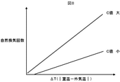
- the ventilation frequency by natural ventilation (hereinafter referred to as natural ventilation frequency) tends to increase as the absolute value of the temperature difference between the room temperature and the outside air temperature (hereinafter referred to as temperature difference ⁇ T) increases.
- temperature difference ⁇ T the absolute value of the temperature difference between the room temperature and the outside air temperature
- the C value is an index of airtightness in the building, and more specifically, is a value indicating the ratio of the gap area to the total floor area of the building.
- the temperature difference ⁇ T becomes larger and the natural ventilation frequency increases as compared with other seasons.
- the natural ventilation frequency when the C value is 2 cm 2 / m 2 or less is expected to be about 0.1 times / h, and the natural ventilation frequency when the C value exceeds 2 cm 2 / m 2 is. About 0.2 times / h is expected.
- the ventilation control unit 202 controls the ventilation device 3 so as to operate with a second ventilation volume smaller than the first ventilation volume when the heating operation is performed by the air conditioning device 4. Specifically, when the heating operation is started by the air conditioner 4, the ventilation control unit 202 generates a control command instructing to change the ventilation volume to the second ventilation volume, and the generated control command is used as the ventilation device. Send to 3.
- the second ventilation volume is the ventilation volume obtained by subtracting the natural ventilation volume from the required ventilation volume (that is, the first ventilation volume), in other words, it corresponds to the ventilation frequency obtained by subtracting the natural ventilation frequency from the required ventilation frequency. Ventilation volume. Since the natural ventilation frequency during heating is expected to be 0.1 times / h or more, in the present embodiment, the natural ventilation frequency during heating is set to 0.1 times / h, whereby the second ventilation volume is set to 0.1 times / h.
- Data on the specified ventilation frequency, natural ventilation frequency, floor area and ceiling height in the house H are set in advance by the user, the contractor, etc. via the operation terminal 5, and are stored in the auxiliary storage device 24 of the control device 2. It is assumed that it is.
- the contractor here means a contractor who is in charge of construction when installing the control device 2, the ventilation device 3, or the air conditioning device 4.
- the ventilation control unit 202 stops the operation of the air conditioner 4 after changing the ventilation volume of the ventilation device 3 to the second ventilation volume, or the operation of the air conditioner 4 is in another operation mode different from the heating operation.
- the ventilation device 3 is controlled so as to operate at the first ventilation volume.
- the ventilation control unit 202 generates a control command instructing to change the ventilation volume to the first ventilation volume, and transmits the generated control command to the ventilation device 3.
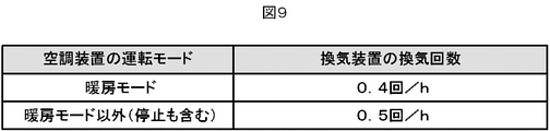
- FIG. 9 shows the relationship between the operation mode of the air conditioner 4 and the ventilation frequency of the ventilation device 3.
- the ventilation control unit 202 executes the control to reduce the ventilation volume of the ventilation device 3 only when the user has previously set to execute the "24-hour ventilation” and the "automatic adjustment of the ventilation volume".
- the notification information generation unit 203 generates notification information for notifying the user of information regarding the operation of the ventilation device 3 based on the control result of the ventilation control unit 202 for the ventilation device 3. For example, the notification information generation unit 203 generates notification information when the ventilation control unit 202 controls to change the ventilation volume of the ventilation device 3.
- the notification information generation unit 203 ventilates by the installation location of the ventilation device 3 and the ventilation device 3. Generates notification information including information indicating that the operation is performed with a reduced amount, the installation location of the air conditioner 4, the heating operation is performed by the air conditioner 4, the start date and time of the heating operation, and the like. do. Further, when the ventilation control unit 202 controls to change the ventilation volume of the ventilation device 3 to the first ventilation volume, the notification information generation unit 203 uses the ventilation device 3 installation location and the ventilation device 3 to provide normal ventilation. Generates notification information that includes information indicating that driving is being performed in quantity.
- the notification information generation unit 203 supplies the generated notification information to the notification information transmission unit 204.
- the notification information transmission unit 204 transmits the notification information generated by the notification information generation unit 203 to the operation terminal 5.
- the notification information generation unit 203 and the notification information transmission unit 204 are examples of the notification means according to the present disclosure.
- the notification information acquisition unit 502 of the operation terminal 5 receives and acquires the notification information transmitted from the control device 2.
- the notification information acquisition unit 502 supplies the acquired notification information to the notification information display unit 503.
- the notification information display unit 503 displays a screen (hereinafter, referred to as a notification screen) based on the content of the notification information. Display on.
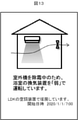
- FIG. 10 shows an example of the notification screen. From the notification screen shown in FIG. 10, the user can see that the air conditioner 4 installed in the LDK is in the heating operation and the ventilation air volume of the ventilation device 3 installed in the bathroom is "weak" (that is, the number of ventilations). It can be grasped that the ventilation operation is in progress (so that the ventilation volume corresponds to 0.4 times / h).
- the notification information display unit 503 deletes the notification screen displayed on the display 50.
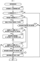
- FIG. 11 is a flowchart showing the procedure of the ventilation control process executed by the control device 2.
- the control device 2 repeatedly executes the ventilation control process periodically (for example, at a 1-minute cycle).
- the air conditioning information acquisition unit 201 acquires air conditioning information from the air conditioning device 4 (step S101).
- the air conditioning information includes information indicating whether or not the vehicle is in operation, information indicating an operation mode, room temperature data, and outside air temperature data.
- the ventilation control unit 202 refers to the setting information table 240 to determine whether or not the user has set the ventilation for 24 hours, in other words, whether or not the ventilation for 24 hours is turned on. (Step S102). When the 24-hour ventilation is turned on (step S102; YES), the ventilation control unit 202 executes the process of step S103. On the other hand, when the ventilation is not turned on for 24 hours (step S102; NO), the control device 2 ends the ventilation control process in this cycle.
- step S103 whether or not the ventilation control unit 202 is set to automatically adjust the ventilation volume of the ventilation device 3 by the user with reference to the setting information table 240, in other words, the automatic ventilation volume. Determine if adjustment is turned on.
- the ventilation control unit 202 executes the process of step S104.
- the ventilation control unit 202 executes the process of step S109.
- step S104 the ventilation control unit 202 determines whether or not the air conditioning device 4 is in the heating operation and the ventilation volume of the ventilation device 3 is the first ventilation volume.
- the ventilation control unit 202 sets the ventilation volume of the ventilation device 3 as the first ventilation volume.
- the ventilation control unit 202 generates a control command instructing to change the ventilation volume to the second ventilation volume, and transmits the generated control command to the ventilation device 3. After that, the process of the control device 2 shifts to step S108.
- step S104 the ventilation control unit 202 determines whether or not the air conditioning device 4 is not in the heating operation and the ventilation volume of the ventilation device 3 is the second ventilation volume (step S106). ..
- step S106 the ventilation control unit 202 sets the ventilation volume of the ventilation device 3 to the first ventilation volume.
- Step S107 the ventilation control unit 202 generates a control command instructing to change the ventilation volume to the first ventilation volume, and transmits the generated control command to the ventilation device 3. After that, the process of the control device 2 shifts to step S108.
- step S106 the control device 2 ends the ventilation control process in this cycle.
- step S108 the notification information generation unit 203 generates the notification information, and the notification information transmission unit 204 transmits the generated notification information to the operation terminal 5. After that, the control device 2 ends the ventilation control process in this cycle.
- step S109 the ventilation control unit 202 determines whether or not the ventilation volume of the ventilation device 3 is the second ventilation volume.
- the ventilation control unit 202 returns the ventilation volume of the ventilation device 3 to the first ventilation volume (step S107). After that, the process of the control device 2 shifts to step S108.
- the control device 2 ends the ventilation control process in this cycle.
- the ventilation device 3 when the heating operation is performed by the air conditioner 4, the ventilation device 3 has a second ventilation volume smaller than the first ventilation volume which is the normal ventilation volume. Operate with ventilation. This makes it possible to prevent a decrease in comfort during heating while ensuring a predetermined ventilation frequency in the house H. Further, since the ventilation volume of the ventilation device 3 is reduced, the power saving of the ventilation device 3 can be achieved, and the increase of the heating load is suppressed, so that the power saving of the air conditioning device 4 can be achieved.
- control device 2 transmits notification information for notifying the user of information regarding the operation of the ventilation device 3, and the operation terminal 5 displays a notification screen based on the notification information.
- the user can easily grasp the operating status of the ventilation device 3.
- the heating operation is performed by the air conditioner 4 assuming that the natural ventilation frequency in winter is expected to be about 0.1 times / h. If so, the number of ventilations by the ventilation device 3 was reduced from 0.5 times / h to 0.4 times / h. However, depending on the C value of the house H, the natural ventilation frequency in winter may be less than 0.1 times / h. Therefore, in order to ensure the specified ventilation frequency with high accuracy, the control device 2 controls to reduce the ventilation volume of the ventilation device 3 only for a part of the period during the heating operation of the air conditioner 4. May be good.
- control device 2 may perform control to reduce the ventilation volume of the ventilation device 3 only during the period from the start of the heating operation of the air conditioner 4 to the time when the room temperature reaches the set temperature.
- the air-conditioning device 4 periodically includes the information indicating the set temperature in the air-conditioning information transmitted to the control device 2.
- the air conditioner 4 operates with a large heating capacity and consumes a large amount of power in order to bring the room temperature closer to the set temperature as soon as possible. Therefore, if the ventilation volume of the house H is large, it takes a long time for the room temperature to reach the set temperature, which causes an increase in the power consumption of the air conditioner 4.
- the specified ventilation frequency can be secured accurately and the air conditioning can be performed. It is possible to suppress an increase in the power consumption of the device 4.
- the notification information of the control device 2 is performed.
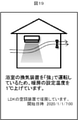
- the generator 203 has the installation location of the ventilation device 3, the operation in which the ventilation volume is reduced by the ventilation device 3, the installation location of the air conditioning device 4, and the heating operation by the air conditioning device 4. Generates notification information that includes information such as the start date and time of the heating operation and the fact that the ventilation volume is reduced until the room warms up.
- the notification information transmission unit 204 transmits the notification information generated by the notification information generation unit 203 to the operation terminal 5. As a result, the operation terminal 5 displays a notification screen as shown in FIG. 12 on the display 50.
- the control device 2 may perform control to reduce the ventilation volume of the ventilation device 3 only in the non-temperature adjustment state during the heating operation of the air conditioning device 4. ..
- This non-temperature controlled state includes thermo-off and defrost.
- Thermo-off means a state in which the compressor 411 of the air conditioner 4 is stopped when the room temperature rises above the set temperature due to the heating operation.
- the air conditioner 4 operates the compressor 411 again when the room temperature drops below the set temperature during the thermo-off (so-called thermo-on).
- defrosting refers to a state in which the refrigerant circuit is switched to cooling in order to melt the frost adhering to the heat exchanger 413 of the outdoor unit 41 during the heating operation.
- thermo-off or defrosting the heating is substantially stopped, so if the ventilation volume of the house H is large, it becomes a factor that impairs the user's comfort. Therefore, by reducing the ventilation volume of the ventilation device 3 only in the non-temperature controlled state during the heating operation of the air conditioning device 4, it is possible to accurately secure the specified ventilation frequency and prevent the deterioration of the user's comfort. can do.
- the notification information generation unit 203 of the control device 2 is the ventilation device.
- the installation location of 3 the operation with reduced ventilation volume by the ventilation device 3, the installation location of the air conditioner 4, the heating operation by the air conditioner 4, the start date and time of the heating operation, non- Generates notification information that includes information indicating that the ventilation volume is reduced during the temperature control state, the type of non-temperature control state (thermooff or defrost), and the like.
- the notification information transmission unit 204 transmits the notification information generated by the notification information generation unit 203 to the operation terminal 5. As a result, the operation terminal 5 displays a notification screen as shown in FIG. 13 on the display 50.
- the ventilation control unit 202 of the control device 2 adjusts the ventilation volume of the ventilation device 3 by transmitting a control command instructing the change of the magnitude of the ventilation air volume (“weak”, “strong”, etc.) to the ventilation device 3.
- the ventilation volume of the ventilation device 3 may be adjusted by transmitting a control command instructing the presence or absence of intermittent operation to the ventilation device 3.
- the ventilation control unit 202 may further instruct the ventilation device 3 at least one of the operation interval and the stop interval.
- Modification example 4 Even when the humidifying operation (including the humidifying and heating operation) is performed by the air conditioner 4, the control device 2 controls to reduce the ventilation volume of the ventilation device 3 as in the heating operation. May be good. This is because the humidification operation is usually carried out in winter, so that the temperature difference ⁇ T described above is large and the natural ventilation frequency is expected to increase.
- the control device 2 estimates the C value based on the pressure difference between the inside of the house H and the outside air, and if the estimated C value is equal to or less than a predetermined threshold value (for example, 2 cm 2 / m 2 ), the natural ventilation frequency during heating is performed. May be set to 0.1 times / h, and if the C value exceeds the threshold value, the natural ventilation frequency during heating may be set to 0.2 times / h.
- the ventilation system 1 further includes a barometric pressure measuring device (not shown) installed inside and outside the house H, respectively.
- Each barometric pressure measuring device includes a communication interface capable of communicating with the control device 2 and a barometric pressure sensor for measuring the barometric pressure, and transmits data indicating the measurement result to the control device 2 in response to a request from the control device 2.
- one or a plurality of ventilation devices responsible for 24-hour ventilation may be installed in the house H, and these ventilation devices may also be configured to be controllable by the control device 2.
- the notification information display unit 503 of the operation terminal 5 displays a notification screen based on the content of the notification information on the display 50. It may be displayed.
- the notification information transmission unit 204 may transmit the notification information to the air conditioner 4, and the remote controller 42 of the air conditioner 4 may display a notification screen based on the received notification information.
- the control device 2 makes the CO 2 concentration equal to or less than the reference value.
- the ventilation volume of the ventilation device 3 may be adjusted.
- the CO 2 measuring device includes a communication interface capable of communicating with the control device 2 and a CO 2 sensor, and periodically (for example, at a 1-minute cycle) data indicating the measured CO 2 concentration is stored in the control device 2. Send to.
- control device 2 has a temperature difference ⁇ T (that is, an absolute value of the temperature difference between the room temperature and the outside air temperature) in advance regardless of whether or not the heating operation is performed by the air conditioner 4. Control is performed to reduce the ventilation volume of the ventilation device 3 when the predetermined threshold is exceeded.
- ⁇ T that is, an absolute value of the temperature difference between the room temperature and the outside air temperature
- FIG. 14 is a flowchart showing a procedure of ventilation control processing executed by the control device 2 of the present embodiment.
- the control device 2 repeatedly executes the ventilation control process periodically (for example, at a 1-minute cycle).
- the air conditioning information acquisition unit 201 acquires air conditioning information from the air conditioning device 4 (step S201).
- the air conditioning information includes at least room temperature data (that is, data indicating the room temperature of the room R measured by the temperature sensor 403) and outside air temperature data (that is, data indicating the outside air temperature measured by the temperature sensor 416). It suffices if it is.
- the ventilation control unit 202 refers to the setting information table 240 to determine whether or not the user has set the ventilation for 24 hours, in other words, whether or not the ventilation for 24 hours is turned on. (Step S202). When the 24-hour ventilation is turned on (step S202; YES), the ventilation control unit 202 executes the process of step S203. On the other hand, when the ventilation is not turned on for 24 hours (step S202; NO), the control device 2 ends the ventilation control process in this cycle.
- step S203 whether or not the ventilation control unit 202 is set to automatically adjust the ventilation volume of the ventilation device 3 by the user with reference to the setting information table 240, in other words, the automatic ventilation volume. Determine if adjustment is turned on.
- the ventilation control unit 202 executes the process of step S204.
- the ventilation control unit 202 executes the process of step S210.
- step S204 the ventilation control unit 202 calculates the temperature difference ⁇ T, which is the absolute value of the temperature difference between the room temperature and the outside air temperature, based on the room temperature data and the outside air temperature data included in the air conditioning information. Then, the ventilation control unit 202 determines whether or not the temperature difference ⁇ T exceeds the threshold value and the ventilation volume of the ventilation device 3 is the first ventilation volume (step S205). When the temperature difference ⁇ T exceeds the threshold value and the ventilation volume of the ventilation device 3 is the first ventilation volume (step S205; YES), the ventilation control unit 202 sets the ventilation volume of the ventilation device 3 as the first ventilation volume. To the second ventilation volume (step S206). After that, the process of the control device 2 shifts to step S209.
- ⁇ T the absolute value of the temperature difference between the room temperature and the outside air temperature
- step S205 the ventilation control unit 202 determines whether or not the temperature difference ⁇ T is equal to or less than the threshold value and the ventilation volume of the ventilation device 3 is the second ventilation volume (step S207).
- step S207 the ventilation control unit 202 sets the ventilation volume of the ventilation device 3 to the first ventilation volume. Return (step S208). After that, the process of the control device 2 shifts to step S209.
- step S207 the control device 2 ends the ventilation control process in this cycle.
- step S209 the notification information generation unit 203 generates the notification information, and the notification information transmission unit 204 transmits the generated notification information to the operation terminal 5.
- the notification information includes information indicating the installation location of the ventilation device 3, the operation with the ventilation volume reduced by the ventilation device 3, the large temperature difference between the inside and the outside, and the like.
- the operation terminal 5 that has received the notification information displays a notification screen based on the received notification information on the display 50 (see FIG. 15).
- step S210 the ventilation control unit 202 determines whether or not the ventilation volume of the ventilation device 3 is the second ventilation volume.
- the ventilation control unit 202 returns the ventilation volume of the ventilation device 3 to the first ventilation volume (step S208). After that, the process of the control device 2 shifts to step S209.
- the control device 2 ends the ventilation control process in this cycle.
- the ventilation device 3 when the temperature difference ⁇ T between the room temperature and the outside air temperature is large, the ventilation device 3 has a second ventilation smaller than the first ventilation volume which is the normal ventilation volume. Drive by quantity. This makes it possible to prevent a decrease in comfort during air conditioning while ensuring a predetermined ventilation frequency in the house H. Further, since the ventilation volume of the ventilation device 3 is reduced, the power saving of the ventilation device 3 can be achieved, and the increase of the air conditioning load at the time of air conditioning is suppressed, so that the power saving of the air conditioning device 4 can be achieved.
- control device 2 transmits notification information for notifying the user of information regarding the operation of the ventilation device 3, and the operation terminal 5 displays a notification screen based on the notification information.
- the user can easily grasp the operating status of the ventilation device 3.
- the control device 2 may use the air temperature measured by a room temperature measuring device (not shown) installed in the house H as the room temperature when calculating the temperature difference ⁇ T.
- This room temperature measuring device includes a communication interface capable of communicating with the control device 2 and a temperature sensor for measuring the air temperature, and periodically transmits data indicating the measured air temperature to the control device 2.
- the air conditioning information transmitted by the air conditioning device 4 to the control device 2 does not need to include room temperature data.
- the control device 2 may use the outside air temperature measured by an outside air temperature measuring device (not shown) installed outdoors as the outside air temperature when calculating the temperature difference ⁇ T. Similar to the above-mentioned room temperature measuring device, this outside air temperature measuring device includes a communication interface capable of communicating with the control device 2 and a temperature sensor for measuring the outside air temperature, and periodically controls data indicating the measured outside air temperature. Send to 2. In this case, the air conditioning information transmitted by the air conditioning device 4 to the control device 2 does not need to include the outside air temperature data. Further, when the modification 1 and the modification 2 are combined, the control device 2 does not need to acquire the air conditioning information from the air conditioning device 4.
- the control device 2 acquires meteorological information in the location area of the house H by communicating with a meteorological server (not shown), and uses the outside air temperature included in the acquired meteorological information as the outside air temperature when calculating the temperature difference ⁇ T. May be good.
- the air conditioning information transmitted by the air conditioning device 4 to the control device 2 does not need to include the outside air temperature data.
- the control device 2 does not need to acquire the air conditioning information from the air conditioning device 4.
- the air conditioner controls the operating frequency of the compressor in proportion to the temperature difference between the room temperature and the set temperature. Therefore, in the control device 2, the operating frequency of the compressor 411 included in the air conditioner 4 exceeds a predetermined threshold value. Only when this is the case, control may be performed to reduce the ventilation volume of the ventilation device 3.
- the air conditioning information transmitted by the air conditioning device 4 to the control device 2 may include at least data indicating the operating frequency of the compressor 411.
- the control device 2 controls to reduce the ventilation volume of the ventilation device 3 in a month (for example, January, February, December, etc.) in which the temperature difference ⁇ T becomes large, which is set in advance by the user, the contractor, or the like. May be. In this case, since the control device 2 does not need to calculate the temperature difference ⁇ T, it is not necessary to acquire the air conditioning information from the air conditioning device 4.
- the required ventilation volume is set to the ventilation volume corresponding to the required ventilation frequency (0.5 times / h) of the house H, but the minimum ventilation volume required per person (hereinafter, per person). Ventilation volume.) ⁇
- FIG. 16 shows the relationship between the required ventilation volume and the number of people in the room R during heating. As shown in FIG. 16, when the number of people in the room exceeds a certain number, the required ventilation volume exceeds the ventilation volume corresponding to the ventilation frequency of 0.5 times / h.
- the room R is present at the time of heating.
- the control device 2 is present. If the required ventilation volume proportional to the number of people in the room R exceeds the ventilation volume corresponding to the ventilation frequency of 0.5 times / h, the necessary ventilation volume is further provided.
- the ventilation device 3 is controlled based on the ventilation volume. Specifically, the control device 2 monitors the number of people in the room R when the air conditioner 4 is in the heating operation, and when the number of people in the room is 5 or more, the ventilation volume of the ventilation device 3 is increased.
- Ventilation volume per person for example, 20 m 3 / h
- x number of people in the room-natural ventilation volume for example, ventilation volume corresponding to 0.1 times / h
- the ventilation volume of the ventilation device 3 in this case is hereinafter referred to as a third ventilation volume.
- the above-mentioned occupancy number acquisition unit is an example of the occupancy acquisition means according to the present disclosure.
- the room number acquisition unit may acquire the number of people in the room R by analyzing the thermal image data acquired by the thermal image sensor 404 included in the air conditioner 4. In this case, the air conditioner 4 periodically (for example, every 1 minute) transmits the thermal image data acquired by the thermal image sensor 404 to the control device 2.
- the room number acquisition unit may acquire the number of people in the room R by receiving the room number data periodically sent from the air conditioner 4. In this case, the air conditioner 4 periodically counts the number of people in the room R based on the thermal image data, and transmits the result data of the number of people in the room to the control device 2.
- the room number acquisition unit may acquire the number of people in the room R by analyzing the image data in the room R taken by a visible camera (not shown) installed in the room R.
- the visible camera is provided with a communication interface capable of communicating with the control device 2 and an image sensor such as a CCD (Charge-Coupled Device) or CMOS (Complementary Metal Oxide Semiconductor), and captures image data in the room R taken. It is transmitted to the control device 2 periodically (for example, at a 1-minute cycle).
- the room number acquisition unit may acquire the number of people in the room R from the CO 2 concentration measured by a CO 2 measuring device (not shown) installed in the room R.
- the CO 2 measuring device includes a communication interface capable of communicating with the control device 2 and a CO 2 sensor, and periodically (for example, at a 1-minute cycle) data indicating the measured CO 2 concentration is stored in the control device 2. Send to.
- the control device 2 controls to increase the ventilation volume of the ventilation device 3 to the third ventilation volume
- the control device 2 generates notification information for notifying the user to that effect and transmits it to the operation terminal 5.
- the notification information includes the installation location of the ventilation device 3, the operation in which the ventilation volume is increased by the ventilation device 3, the installation location of the air conditioner 4, and the heating operation by the air conditioner 4. Information indicating that, the start date and time of the heating operation, the large number of people in the room, etc. are included.
- the operation terminal 5 displays a notification screen as shown in FIG. 17 on the display 50.
- the same effect as that of the first embodiment can be obtained, and the deterioration of comfort is prevented even when the number of people in the room R increases during heating. can.
- Modification 1 In the ventilation system 1, when the control device 2 has a configuration capable of controlling a ventilation device other than the ventilation device 3 (for example, a ventilation fan installed in a bedroom, a toilet, etc.), it needs to be proportional to the number of people in the room R. When the ventilation volume exceeds the ventilation volume corresponding to the ventilation frequency of 0.5 times / h, the control device 2 causes the ventilation devices other than the ventilation device 3 to perform the ventilation operation in addition to the ventilation device 3. May be good. By doing so, even if the third ventilation volume exceeds the effective ventilation volume of the ventilation device 3, it becomes possible to cope with it.
- a ventilation device other than the ventilation device 3 for example, a ventilation fan installed in a bedroom, a toilet, etc.
- Modification 2 In the first modification, when a plurality of ventilation devices including the ventilation device 3 are operated, the power consumption increases accordingly. Therefore, when the control device 2 can control the range hood, the control device 2 may operate the range hood independently to secure the required ventilation volume proportional to the number of people in the room R. In addition, the ventilation volume of the range hood is generally as large as 250 m 3 / h even if the ventilation air volume is operated at "weak", so that the ventilation may be excessive. Therefore, the control device 2 may be controlled so as not to cause excessive ventilation, such as operating the range hood for a certain period of time (for example, 10 minutes) or intermittently.
- the ventilation system 1A of the present embodiment includes a control device 2A, a ventilation device 3, an air conditioning device 4, and an operation terminal 5.
- the control device 2A is an example of the control device according to the present disclosure. Like the control device 2 of the first embodiment, the control device 2A is installed at an appropriate place in the house H, and the ventilation device 3, the air conditioner 4, and the operation terminal 5 are installed via the home network N1 constructed in the house H. It is a device that controls the operation of the ventilation device 3 based on the operating state of the air conditioner 4 by connecting to the air conditioner 4 in a communicable manner. Further, the control device 2A also controls to increase the heating of the air conditioner 4 so as not to reduce the comfort of the user when the ventilation device 3 is in operation.
- the hardware configuration of the control device 2A is the same as that of the control device 2 of the first embodiment (see FIG. 2).
- the control device 2A is different from the control device 2 of the first embodiment in that the ventilation control unit 202A is provided instead of the ventilation control unit 202 and the air conditioning control unit 205 is provided instead of the air conditioning information acquisition unit 201. do.
- the ventilation control unit 202A is an example of the ventilation control means according to the present disclosure.
- the ventilation control unit 202A controls the ventilation device 3 in consideration of the natural ventilation volume, similarly to the ventilation control unit 202 of the first embodiment. Further, the ventilation control unit 202A periodically (for example, every 1 minute) acquires operation information which is information related to the current operation of the ventilation device 3.
- the ventilation control unit 202A periodically transmits a command for requesting operation information to the ventilation device 3 (hereinafter referred to as an operation information request command).
- the ventilation device 3 Upon receiving the operation information request command, the ventilation device 3 generates operation information including information indicating whether or not the operation is in progress and information indicating the magnitude of the ventilation air volume (“weak”, “strong”, etc.). Then, the generated operation information is transmitted to the control device 2A.
- the ventilation control unit 202A After transmitting the operation information request command, the ventilation control unit 202A receives the operation information sent from the ventilation device 3 and supplies the received operation information to the air conditioning control unit 205.
- the air conditioning control unit 205 is an example of the air conditioning control means according to the present disclosure.
- the air conditioning control unit 205 controls the air conditioning device 4 based on the operation information supplied from the ventilation control unit 202A. Specifically, the air conditioning control unit 205 controls to raise the set temperature of the air conditioning device 4 at the time of heating according to the ventilation air volume of the ventilation device 3. For example, when the ventilation air volume of the ventilation device 3 is "weak", the air conditioning control unit 205 transmits a control command for raising the set temperature of the air conditioning device 4 by 0.5 ° C. to the air conditioning device 4, and the ventilation device 3 has a control command. When the ventilation air volume is "strong", a control command for raising the set temperature of the air conditioner 4 by 1 ° C. is transmitted to the air conditioner 4.
- the ventilation volume of the ventilation device 3 is the second ventilation during the heating operation of the air conditioning device 4, as in the first embodiment. It is reduced to a volume, and its ventilation air volume is smaller than usual (eg, "weak") and never “strong". However, when it is set not to execute the "automatic adjustment of the ventilation volume", the ventilation air volume may become “strong” as described above during the heating operation of the air conditioner 4.
- the notification information generation unit 203 determines the installation location of the ventilation device 3, the size of the ventilation air volume of the ventilation device 3, and the installation of the air conditioner 4. Notification information including information indicating the location, that the heating operation is being performed by the air conditioner 4, the start date and time of the heating operation, the rising value of the set temperature, and the like is generated.
- the notification information transmission unit 204 transmits the notification information generated by the notification information generation unit 203 to the operation terminal 5. As a result, the operation terminal 5 displays a notification screen as shown in FIG. 19 on the display 50.
- the same effect as that of the first embodiment can be obtained, and the set temperature of the air conditioner 4 is adjusted according to the magnitude of the ventilation air volume of the ventilation device 3. Therefore, it is possible to further prevent a decrease in comfort during heating.
- control device 2A when the heating operation is performed by the air conditioner 4 while the ventilation device 3 is in the ventilation operation, a person is present in a locally cooled place (for example, near an air supply port (not shown) or near a window) in the house H.
- the air conditioner 4 may be controlled so that the sensible temperature of the person becomes the set temperature.
- the control device 2A acquires the position of a person based on the thermal image data acquired by the thermal image sensor 404 included in the air conditioner 4.
- the control device 2A may acquire the position of a person based on the image data in the room taken by a visible camera (not shown) installed in the house H.
- This visible camera is provided with a communication interface capable of communicating with the control device 2A and an image sensor such as a CCD or CMOS, and periodically (for example, at a 1-minute cycle) transmits the image data of the photographed room to the control device 2A. do.
- an image sensor such as a CCD or CMOS
- the sensible temperature can be obtained by the control device 2A by subtracting a value estimated based on the outside air temperature from the room temperature.
- FIG. 20 is a diagram showing the overall configuration of the ventilation system 1B according to the fifth embodiment of the present disclosure.
- the ventilation system 1B includes a ventilation device 3, an air conditioner 4, an operation terminal 5A, and a server 6.
- the operation terminal 5A is an electronic device that serves as an interface with the user in the ventilation system 1B.
- the operation terminal 5A is a smart device such as a smartphone or a tablet terminal, a PC, a television, or the like.
- the hardware configuration of the operation terminal 5A is the same as that of the operation terminal 5 of the first embodiment (see FIG. 5). The details of the functions of the operation terminal 5A will be described later.
- the server 6 is an example of the control device according to the present disclosure.
- the server 6 is a server computer installed and operated by a manufacturer, a sales company, or the like of the ventilation device 3 and the air conditioning device 4, and is a so-called cloud server.
- the server 6 includes a communication interface 60, a CPU 61, a ROM 62, a RAM 63, and an auxiliary storage device 64. These components are connected to each other via a bus 65.
- the communication interface 60 is hardware for communicating with other devices via a wide area network N2 such as the Internet.
- the CPU 61 controls the server 6 in an integrated manner. Details of the functions of the server 6 realized by the CPU 61 will be described later.
- the ROM 62 stores a plurality of firmwares and data used when executing these firmwares.
- the RAM 63 is used as a work area of the CPU 61.
- the auxiliary storage device 64 is composed of a readable / writable non-volatile semiconductor memory, an HDD, or the like.
- the non-volatile semiconductor memory that can be read and written is, for example, EEPROM, flash memory, or the like.
- the auxiliary storage device 64 stores various programs including a program for providing a 24-hour ventilation service (hereinafter referred to as a ventilation service program) and data used when executing these programs.
- Ventilation service programs can also be stored and distributed in computer-readable recording media such as CD-ROMs, DVDs, magneto-optical disks, USB memory, memory cards, HDDs, and SSDs. Is.
- FIG. 22 is a block diagram showing a functional configuration of the server 6 and the operation terminal 5A.
- the server 6 includes a registration information acquisition unit 600, a setting information acquisition unit 601, an air conditioning information acquisition unit 602, a ventilation control unit 603, a notification information generation unit 604, and a notification information transmission unit 605. And prepare.
- These functional units of the server 6 are realized by the CPU 61 executing the above-mentioned ventilation service program stored in the auxiliary storage device 64.
- the operation terminal 5A includes a setting reception unit 500, a setting information transmission unit 501A, a notification information acquisition unit 502A, a notification information display unit 503, a registration reception unit 504, and a registration information transmission unit 505. These functional units of the operation terminal 5A are realized by the CPU 53 executing a ventilation application which is an application program related to the operation of the ventilation device 3 stored in the auxiliary storage device 56.
- the registration reception unit 504 receives input of necessary information for user registration to the server 6 from the user.
- the registration reception unit 504 displays a user registration screen (not shown), and the user inputs necessary information such as a user ID (identification) and a password via the user registration screen.
- the registration reception unit 504 controls the ventilation device 3 by communication via a router 7 which is a wireless LAN router such as Wi-Fi (registered trademark) installed in the house H.
- the product information of the ventilation device 3 is acquired from the circuit.
- the product information includes, for example, a serial number, a model name, a model number, and the like.
- the registration reception unit 504 acquires the product information of the air conditioner 4 from the control circuit 400 of the indoor unit 40 by communication via the router 7.
- the registration information transmission unit 505 transmits the registration information including the user ID, password, etc. input by the user and the product information acquired from each of the ventilation device 3 and the air conditioning device 4 to the server 6 via the router 7. ..
- the registration information acquisition unit 600 of the server 6 receives and acquires the registration information transmitted from the operation terminal 5A.
- the registration information acquisition unit 600 stores the acquired registration information (user ID, password, product information of the ventilation device 3 and the air conditioning device 4, etc.) in the customer DB 640.
- the customer DB 640 is a database for managing information about a user who is a purchaser of the ventilation device 3 and the air conditioning device 4 and has registered as a user, that is, a customer, and is stored in the auxiliary storage device 64.
- the setting information transmission unit 501A of the operation terminal 5A transmits the setting information, which is the information indicating the user's setting received by the setting reception unit 500, to the server 6 via the router 7.
- the setting information acquisition unit 601 of the server 6 receives and acquires the setting information transmitted from the operation terminal 5A.
- the setting information acquisition unit 601 stores the acquired setting information in the customer DB 640.
- the air conditioning information acquisition unit 602 of the server 6 periodically acquires air conditioning information from each customer's house, that is, the air conditioning device 4 of each house H. For example, the air conditioning information acquisition unit 602 acquires air conditioning information from the air conditioning device 4 at a cycle of 1 minute. Specifically, the air-conditioning information acquisition unit 602 periodically transmits a command for requesting air-conditioning information to the air-conditioning device 4 (hereinafter, referred to as an air-conditioning information request command). When the air conditioner 4 receives an air conditioning information request command via the router 7, it generates air conditioning information, which is information related to the current air conditioning operation, and transmits the generated air conditioning information to the server 6 via the router 7.
- the information includes information indicating whether or not the vehicle is in operation, information indicating the operation mode, room temperature data, and outside temperature data.
- the room temperature data is data indicating the room temperature measured by the temperature sensor 403 included in the indoor unit 40
- the outside air temperature data is data indicating the outside air temperature measured by the temperature sensor 416 included in the outdoor unit 41.
- the air conditioning information acquisition unit 602 receives and acquires the air conditioning information sent from the air conditioning device 4 after transmitting the air conditioning information request command.
- the air conditioning information acquisition unit 602 supplies the acquired air conditioning information to the ventilation control unit 603.
- the ventilation control unit 603 is an example of the ventilation control means according to the present disclosure, and controls the ventilation device 3 in consideration of the natural ventilation volume.
- the method of control by the ventilation control unit 603 is the same as that of the ventilation control unit 202 of the control device 2 in the first embodiment.
- the notification information generation unit 604 generates notification information for notifying the user of information regarding the operation of the ventilation device 3 based on the control result for the ventilation device 3 by the ventilation control unit 603.
- the content of the notification information is the same as that of the first embodiment.
- the notification information transmission unit 605 transmits the notification information generated by the notification information generation unit 604 to the operation terminal 5A of the customer.
- the notification information generation unit 604 and the notification information transmission unit 605 are examples of the notification means according to the present disclosure.
- the notification information acquisition unit 502A of the operation terminal 5A receives and acquires the notification information transmitted from the server 6 via the router 7.
- the notification information acquisition unit 502A supplies the acquired notification information to the notification information display unit 503.
- the notification information display unit 503 displays a notification screen based on the content of the notification information on the display 50 (see FIG. 10). ..
- the notification information display unit 503 deletes the notification screen displayed on the display 50.
- the ventilation device 3 when the heating operation is performed by the air conditioner 4, the ventilation device 3 has a second ventilation volume smaller than the first ventilation volume which is the normal ventilation volume. Operate with ventilation. This makes it possible to prevent a decrease in comfort during heating while ensuring a predetermined ventilation frequency in the house H. Further, since the ventilation volume of the ventilation device 3 is reduced, the power saving of the ventilation device 3 can be achieved, and the increase of the heating load is suppressed, so that the power saving of the air conditioning device 4 can be achieved.
- the server 6 transmits notification information for notifying the user of information regarding the operation of the ventilation device 3 to the operation terminal 5A, and the operation terminal 5A displays a notification screen based on the notification information.
- the user can easily grasp the operating status of the ventilation device 3.
- each customer since the ventilation device 3 of each customer's house is controlled by the server 6, each customer does not need to install a dedicated controller at home. Therefore, it is possible to provide a 24-hour ventilation service to a customer at a low price.
- Communication between the ventilation device 3 and the server 6 may be performed based on LPWA (Low Power Wide Area) in 5G (5th generation mobile communication system), and similarly, with the air conditioning device 4.
- the communication with the server 6 may be performed based on the LPWA in 5G, or the communication between the operation terminal 5A and the server 6 may be performed based on the LPWA in 5G. May be good.
- the ventilation device according to the present disclosure is not limited to the type 3 ventilation type ventilation device that only exhausts, and may be a type 1 ventilation type ventilation device that supplies and exhausts air. It may be a second-class ventilation type ventilation device that performs only. Further, in the case of the first-class ventilation system, the ventilation device according to the present disclosure is a ventilation device having a function of exchanging sensible heat and latent heat between the outside air to be taken in and the indoor air to be exhausted (so-called Rosnai). May be good.
- the air conditioner according to the present disclosure may be configured to include one outdoor unit and a plurality of indoor units, or may be an air conditioner compatible with a so-called whole building air conditioner system, or may be a floor. It may be a heating system, a radiant heating / cooling system, or the like. Further, in the case of controlling to reduce the ventilation volume of the ventilation device 3 during the humidifying operation as in the modified example 4 of the first embodiment, the air conditioning device according to the present disclosure may be a humidifier.
- the air conditioner according to the present disclosure may include the configuration of the ventilation device 3 in addition to the configuration of the air conditioner 4.
- all or part of the functional part of the control device 2 may be realized by dedicated hardware, or all or part of the functional part of the operation terminal 5 (see FIG. 7). May be realized by dedicated hardware, or all or part of the functional part (see FIG. 18) of the control device 2A may be realized by dedicated hardware, or the server 6 may be realized. All or part of the functional part (see FIG. 22) may be realized by dedicated hardware, or all or part of the functional part (see FIG. 22) of the operation terminal 5A may be realized by dedicated hardware. It may be realized by.
- Dedicated hardware is, for example, a single circuit, a composite circuit, a programmed processor, an ASIC (Application Specific Integrated Circuit), an FPGA (Field-Programmable Gate Array), or a combination thereof.
- This disclosure is also applicable to systems that ventilate buildings other than houses.
- the present disclosure can be suitably adopted for a ventilation system for ventilating a building.
- 1,1A, 1B ventilation system 2,2A control device, 3 ventilation device, 4 air conditioner, 5,5A operation terminal, 6 server, 7 router, 20,52,60 communication interface, 21,53,61 CPU, 22 , 54,62 ROM, 23,55,63 RAM, 24,56,64 auxiliary storage device, 25,57,65 bus, 40 indoor unit, 41 outdoor unit, 42 remote control, 43 refrigerant pipe, 44 communication line, 50 display , 51 Operation reception unit, 200,601 Setting information acquisition unit, 201,602 Air conditioning information acquisition unit, 202,202A,603 Ventilation control unit, 203,604 Notification information generation unit, 204,605 Notification information transmission unit, 205 Air conditioning control Part, 240 setting information table, 400,410 control circuit, 401,413 heat exchanger, 402,414 fan, 403,416 temperature sensor, 404 thermal image sensor, 411 compressor, 412 four-way valve, 415 expansion valve, 500 setting Reception unit, 501,501A setting information transmission unit, 502,502A notification information acquisition unit
Landscapes
- Engineering & Computer Science (AREA)
- Chemical & Material Sciences (AREA)
- Combustion & Propulsion (AREA)
- Mechanical Engineering (AREA)
- General Engineering & Computer Science (AREA)
- Signal Processing (AREA)
- Physics & Mathematics (AREA)
- Fuzzy Systems (AREA)
- Mathematical Physics (AREA)
- Fluid Mechanics (AREA)
- Air Conditioning Control Device (AREA)
- Ventilation (AREA)
Priority Applications (5)
| Application Number | Priority Date | Filing Date | Title |
|---|---|---|---|
| EP20954086.3A EP4215829A4 (en) | 2020-09-16 | 2020-09-16 | CONTROL DEVICE, VENTILATION SYSTEM, AIR CONDITIONING DEVICE, VENTILATION CONTROL METHOD AND PROGRAM |
| JP2022550098A JP7433458B2 (ja) | 2020-09-16 | 2020-09-16 | 制御装置、換気システム、空調装置、換気制御方法及びプログラム |
| US18/004,981 US20230341142A1 (en) | 2020-09-16 | 2020-09-16 | Control device, ventilation system, air-conditioning apparatus, ventilation control method, and recording medium |
| CN202080103831.5A CN116034237A (zh) | 2020-09-16 | 2020-09-16 | 控制装置、换气系统、空调装置、换气控制方法和程序 |
| PCT/JP2020/035109 WO2022059100A1 (ja) | 2020-09-16 | 2020-09-16 | 制御装置、換気システム、空調装置、換気制御方法及びプログラム |
Applications Claiming Priority (1)
| Application Number | Priority Date | Filing Date | Title |
|---|---|---|---|
| PCT/JP2020/035109 WO2022059100A1 (ja) | 2020-09-16 | 2020-09-16 | 制御装置、換気システム、空調装置、換気制御方法及びプログラム |
Publications (1)
| Publication Number | Publication Date |
|---|---|
| WO2022059100A1 true WO2022059100A1 (ja) | 2022-03-24 |
Family
ID=80776575
Family Applications (1)
| Application Number | Title | Priority Date | Filing Date |
|---|---|---|---|
| PCT/JP2020/035109 Ceased WO2022059100A1 (ja) | 2020-09-16 | 2020-09-16 | 制御装置、換気システム、空調装置、換気制御方法及びプログラム |
Country Status (5)
| Country | Link |
|---|---|
| US (1) | US20230341142A1 (https=) |
| EP (1) | EP4215829A4 (https=) |
| JP (1) | JP7433458B2 (https=) |
| CN (1) | CN116034237A (https=) |
| WO (1) | WO2022059100A1 (https=) |
Cited By (1)
| Publication number | Priority date | Publication date | Assignee | Title |
|---|---|---|---|---|
| JP2022057060A (ja) * | 2020-09-30 | 2022-04-11 | パナソニックIpマネジメント株式会社 | 換気装置 |
Families Citing this family (1)
| Publication number | Priority date | Publication date | Assignee | Title |
|---|---|---|---|---|
| JP7729501B1 (ja) * | 2025-01-08 | 2025-08-26 | 積水ハウス株式会社 | 室温制御方法、室温制御装置、プログラム、及びこれを備えた室温制御システム |
Citations (6)
| Publication number | Priority date | Publication date | Assignee | Title |
|---|---|---|---|---|
| JP2005337647A (ja) | 2004-05-31 | 2005-12-08 | Toshiba Corp | 住宅設備制御装置 |
| JP2007187334A (ja) * | 2006-01-11 | 2007-07-26 | Matsushita Electric Ind Co Ltd | 空気調和機 |
| JP2014134343A (ja) * | 2013-01-10 | 2014-07-24 | Daikin Ind Ltd | 空気調和システム |
| JP2015148347A (ja) * | 2014-02-04 | 2015-08-20 | マックス株式会社 | 送風装置 |
| JP2016145679A (ja) * | 2015-02-09 | 2016-08-12 | パナソニックIpマネジメント株式会社 | 換気装置 |
| JP2018186331A (ja) * | 2017-04-24 | 2018-11-22 | パナソニックIpマネジメント株式会社 | 制御システム、シーン制御の実行方法、及び、プログラム |
Family Cites Families (9)
| Publication number | Priority date | Publication date | Assignee | Title |
|---|---|---|---|---|
| JP4251891B2 (ja) * | 2003-03-17 | 2009-04-08 | 東邦瓦斯株式会社 | 空調システム |
| JP2007198722A (ja) * | 2005-12-26 | 2007-08-09 | Asahi Kasei Homes Kk | 建物用常時換気システムおよびこれを備えた住宅 |
| CN103229116B (zh) * | 2010-12-31 | 2016-12-07 | 谷歌公司 | 智能恒温器控制hvac系统的灵活功能划分 |
| JP6146031B2 (ja) * | 2013-02-04 | 2017-06-14 | ダイキン工業株式会社 | 空気調和システム |
| WO2014184883A1 (ja) * | 2013-05-14 | 2014-11-20 | 三菱電機株式会社 | 空気調和システム |
| JP6175937B2 (ja) | 2013-06-27 | 2017-08-09 | 三菱電機株式会社 | 換気制御装置、換気システムおよび建物 |
| JP2016156535A (ja) * | 2015-02-24 | 2016-09-01 | パナソニックIpマネジメント株式会社 | 換気装置 |
| CN107636396A (zh) * | 2015-07-29 | 2018-01-26 | 三菱电机株式会社 | 空气调和系统、控制器以及程序 |
| WO2019146121A1 (ja) * | 2018-01-29 | 2019-08-01 | 三菱電機株式会社 | 空調システムおよび換気装置 |
-
2020
- 2020-09-16 EP EP20954086.3A patent/EP4215829A4/en not_active Withdrawn
- 2020-09-16 US US18/004,981 patent/US20230341142A1/en active Pending
- 2020-09-16 JP JP2022550098A patent/JP7433458B2/ja active Active
- 2020-09-16 WO PCT/JP2020/035109 patent/WO2022059100A1/ja not_active Ceased
- 2020-09-16 CN CN202080103831.5A patent/CN116034237A/zh active Pending
Patent Citations (6)
| Publication number | Priority date | Publication date | Assignee | Title |
|---|---|---|---|---|
| JP2005337647A (ja) | 2004-05-31 | 2005-12-08 | Toshiba Corp | 住宅設備制御装置 |
| JP2007187334A (ja) * | 2006-01-11 | 2007-07-26 | Matsushita Electric Ind Co Ltd | 空気調和機 |
| JP2014134343A (ja) * | 2013-01-10 | 2014-07-24 | Daikin Ind Ltd | 空気調和システム |
| JP2015148347A (ja) * | 2014-02-04 | 2015-08-20 | マックス株式会社 | 送風装置 |
| JP2016145679A (ja) * | 2015-02-09 | 2016-08-12 | パナソニックIpマネジメント株式会社 | 換気装置 |
| JP2018186331A (ja) * | 2017-04-24 | 2018-11-22 | パナソニックIpマネジメント株式会社 | 制御システム、シーン制御の実行方法、及び、プログラム |
Non-Patent Citations (1)
| Title |
|---|
| See also references of EP4215829A4 |
Cited By (2)
| Publication number | Priority date | Publication date | Assignee | Title |
|---|---|---|---|---|
| JP2022057060A (ja) * | 2020-09-30 | 2022-04-11 | パナソニックIpマネジメント株式会社 | 換気装置 |
| JP7522962B2 (ja) | 2020-09-30 | 2024-07-26 | パナソニックIpマネジメント株式会社 | 換気装置 |
Also Published As
| Publication number | Publication date |
|---|---|
| EP4215829A1 (en) | 2023-07-26 |
| EP4215829A4 (en) | 2023-11-01 |
| JPWO2022059100A1 (https=) | 2022-03-24 |
| JP7433458B2 (ja) | 2024-02-19 |
| US20230341142A1 (en) | 2023-10-26 |
| CN116034237A (zh) | 2023-04-28 |
Similar Documents
| Publication | Publication Date | Title |
|---|---|---|
| CN110662925B (zh) | 空调系统 | |
| CN104285106A (zh) | 空气调节系统 | |
| KR20170103562A (ko) | 공기 조화를 위한 제어 장치 및 그 제어 방법 | |
| JP6730536B1 (ja) | 空気調和装置、運転制御方法およびプログラム | |
| JP7433458B2 (ja) | 制御装置、換気システム、空調装置、換気制御方法及びプログラム | |
| JP2022056416A (ja) | 制御装置、空調システム、空調機制御方法及びプログラム | |
| JP2015187510A (ja) | 換気・空調システム | |
| JPWO2020035911A1 (ja) | 空調装置、制御装置、空調方法及びプログラム | |
| JPWO2020035913A1 (ja) | 空調装置、制御装置、空調方法及びプログラム | |
| JP6288138B2 (ja) | 制御装置 | |
| JP7313563B2 (ja) | 空調機、制御装置、空調システム及び空調方法 | |
| WO2020035908A1 (ja) | 空調装置、制御装置、空調方法及びプログラム | |
| WO2020035907A1 (ja) | 空調装置、制御装置、空調方法及びプログラム | |
| JPWO2017170491A1 (ja) | 制御装置、空調システム、空調方法及びプログラム | |
| JP2019196885A (ja) | 制御装置、空調機、空調システム、空調機制御方法及びプログラム | |
| JP2023147391A (ja) | 空調システム | |
| JP2023047932A (ja) | 空調装置、制御装置、空調システム及び空調制御方法 | |
| JP6175937B2 (ja) | 換気制御装置、換気システムおよび建物 | |
| JP7016601B2 (ja) | 空調装置、制御装置、空調方法及びプログラム | |
| JP6479736B2 (ja) | 空気調和機 | |
| JP6116442B2 (ja) | 換気システム、及び、換気システムの制御方法 | |
| JP2023172150A (ja) | 空調システム、制御装置、空調装置及び室外機台数制御方法 | |
| JP7253915B2 (ja) | 制御装置、空調機、空調システム、空調機制御方法及びプログラム | |
| JP6368550B2 (ja) | 空気調和機 | |
| EP4230925A1 (en) | Air conditioner and air conditioning control method |
Legal Events
| Date | Code | Title | Description |
|---|---|---|---|
| 121 | Ep: the epo has been informed by wipo that ep was designated in this application |
Ref document number: 20954086 Country of ref document: EP Kind code of ref document: A1 |
|
| ENP | Entry into the national phase |
Ref document number: 2022550098 Country of ref document: JP Kind code of ref document: A |
|
| NENP | Non-entry into the national phase |
Ref country code: DE |
|
| ENP | Entry into the national phase |
Ref document number: 2020954086 Country of ref document: EP Effective date: 20230417 |