WO2022054844A1 - 線条体支持構造及びロボット - Google Patents
線条体支持構造及びロボット Download PDFInfo
- Publication number
- WO2022054844A1 WO2022054844A1 PCT/JP2021/033043 JP2021033043W WO2022054844A1 WO 2022054844 A1 WO2022054844 A1 WO 2022054844A1 JP 2021033043 W JP2021033043 W JP 2021033043W WO 2022054844 A1 WO2022054844 A1 WO 2022054844A1
- Authority
- WO
- WIPO (PCT)
- Prior art keywords
- striatum
- elastic body
- link
- support
- support structure
- Prior art date
- Legal status (The legal status is an assumption and is not a legal conclusion. Google has not performed a legal analysis and makes no representation as to the accuracy of the status listed.)
- Ceased
Links
Images







Classifications
-
- B—PERFORMING OPERATIONS; TRANSPORTING
- B25—HAND TOOLS; PORTABLE POWER-DRIVEN TOOLS; MANIPULATORS
- B25J—MANIPULATORS; CHAMBERS PROVIDED WITH MANIPULATION DEVICES
- B25J9/00—Program-controlled manipulators
- B25J9/10—Program-controlled manipulators characterised by positioning means for manipulator elements
- B25J9/106—Program-controlled manipulators characterised by positioning means for manipulator elements with articulated links
-
- B—PERFORMING OPERATIONS; TRANSPORTING
- B25—HAND TOOLS; PORTABLE POWER-DRIVEN TOOLS; MANIPULATORS
- B25J—MANIPULATORS; CHAMBERS PROVIDED WITH MANIPULATION DEVICES
- B25J19/00—Accessories fitted to manipulators, e.g. for monitoring, for viewing; Safety devices combined with or specially adapted for use in connection with manipulators
- B25J19/0025—Means for supplying energy to the end effector
-
- H—ELECTRICITY
- H02—GENERATION; CONVERSION OR DISTRIBUTION OF ELECTRIC POWER
- H02G—INSTALLATION OF ELECTRIC CABLES OR LINES, OR OF COMBINED OPTICAL AND ELECTRIC CABLES OR LINES
- H02G11/00—Arrangements of electric cables or lines between relatively-movable parts
-
- H—ELECTRICITY
- H02—GENERATION; CONVERSION OR DISTRIBUTION OF ELECTRIC POWER
- H02G—INSTALLATION OF ELECTRIC CABLES OR LINES, OR OF COMBINED OPTICAL AND ELECTRIC CABLES OR LINES
- H02G3/00—Installations of electric cables or lines or protective tubing therefor in or on buildings, equivalent structures or vehicles
- H02G3/02—Details
- H02G3/04—Protective tubing or conduits, e.g. cable ladders or cable troughs
- H02G3/0462—Tubings, i.e. having a closed section
- H02G3/0468—Corrugated
-
- H—ELECTRICITY
- H02—GENERATION; CONVERSION OR DISTRIBUTION OF ELECTRIC POWER
- H02G—INSTALLATION OF ELECTRIC CABLES OR LINES, OR OF COMBINED OPTICAL AND ELECTRIC CABLES OR LINES
- H02G3/00—Installations of electric cables or lines or protective tubing therefor in or on buildings, equivalent structures or vehicles
- H02G3/30—Installations of cables or lines on walls, floors or ceilings
- H02G3/32—Installations of cables or lines on walls, floors or ceilings using mounting clamps
Definitions
- the present invention relates to a striatal support structure and a robot, and particularly to a striatal support structure and a robot that alleviate twisting of the striatum.
- Patent Document 1 discloses a cable processing device that protects and holds a cable wired in two relative swivel members in an industrial robot.
- the cable processing device grips the cable and slides on the sliding shaft with a sliding shaft mounted laterally intersecting the length direction of the relative swivel member inside at least one of the two relative swivel members.
- the sliding shaft is provided with a clamp member that slidably holds the clamp member on a substantially circumference centered on the swivel center of the relative swivel member. The twist is eliminated.
- Patent Document 2 describes a robot arm having a first frame and a second frame rotatably connected around a joint axis, a cable arranged along the side surfaces of the first frame and the second frame, and a cable.
- a first fixing member that is fixed to the side surface of one frame
- a second fixing member that fixes the cable to the side surface of the second frame
- a holding member that holds a portion between the first fixing member and the second fixing member of the cable.
- a support mechanism that regulates the movement of the holding member in the axial direction of the joint axis and supports the holding member so that the holding member can move in the direction orthogonal to the axial direction of the joint axis following the bending motion of the cable.
- a robot equipped with is described.
- One aspect of the present disclosure is two links rotatably connected around a predetermined axis, a striatum laid across the two links, and at least two links distant from the axis.
- a striatal support structure comprising an elastic body directly or indirectly attached to one side to directly or indirectly support the striatum.
- the elastic body is passively deformed in the direction in which the striatum is desired to escape in response to the rotation of the link, and the striatum is suddenly deformed to secure a twisting distance of the striatum. Suppresses twisting or reduces the amount of twisting of the striatum. This can alleviate the twisting of the striatum.
- the elastic body limits the operating range of the striatum to some extent, it is possible to prevent the striatum from being worn due to contact between the striatum and a peripheral object. As a result, the life of the striatum is improved. By improving the life of the striatum, it will be possible to adopt inexpensive striatum that could not be adopted until now.
- FIG. 2 is a cross-sectional view taken along the line II-II of the second link. It is a perspective view which shows an example of an elastic body. It is a perspective view which shows an example of a support member. It is a VV cross-sectional view of the 2nd link which shows the operation example of an elastic body. It is a VV cross-sectional view of the 2nd link which shows the operation example of an elastic body. It is a perspective view of the striatum support structure applied to the robot of another form. It is a perspective view which shows an example of an elastic body. It is a perspective view which shows the deformation example of an elastic body.
- FIG. 1 is a perspective view of the robot 1 provided with the striatal support structure of the present embodiment.
- the robot 1 is, for example, a horizontal articulated robot (SCARA robot), and includes a first link 11, a second link 12, a third link 13, and a tip axis 14.
- the first link 11 is, for example, a hollow base
- the second link 12 and the third link 13 are, for example, a hollow arm member
- the tip shaft 14 is, for example, a hollow ball screw spline.
- the first link 11 and the second link 12 are rotatably connected around the J1 axis
- the second link 12 and the third link 13 are rotatably connected around the J2 axis.
- the third link 13 and the tip shaft 14 are rotatably connected along the J3 axis and rotatably connected around the J4 axis.
- the J1 to J4 axes are parallel to each other.
- actuators such as electric motors and speed reducers are arranged on the J1 to J4 axes, and cables such as signal lines and power lines are connected to the actuators.
- a tool such as a suction hand or a screwdriver is detachably attached to the tip shaft 14, and a cable, an air tube, or the like is connected to the tool. Striatums such as cables and air tubes (see FIG.
- first link 11, second link 12, third link 13, tip shaft 14, tool in order to avoid contact with surrounding objects and people. It is advisable to lay it over the inside of such a building.
- the striatum is connected to a control device (not shown) that controls the robot 1 and the tool.
- members constituting the rotating shaft portion such as the first link 11, the second link 12, the third link 13, the tip shaft 14, and the tool are referred to as "links".
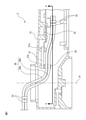
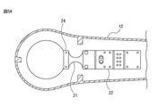
- FIG. 2 is a sectional view taken along line II-II of the second link 12.
- the striatal support structure 2 is applied to the rotation shaft portion between the two links.
- the striatum support structure 2 is laid over the first link 11 (see FIG. 1) and the second link 12 rotatably connected around the J1 axis, and the first link 11 and the second link 12.
- the striatum 20 is provided with an elastic body 21 indirectly fixed to the second link 12 at a position away from the J1 axis and indirectly supporting the striatum 20.
- the striatum 20 includes, for example, a cable 20a, an air tube 20b, and the like.
- the striatum 20 may be fixed to each of the first link 11 and the second link 12 at a predetermined position by, for example, a fastener 23 such as a binding band.
- a fastener 23 such as a binding band.
- the elastic body 21 is formed of an elastomer such as rubber.
- the elastic body 21 includes a fixed end 21a indirectly fixed to the second link 12 and a free end 21b that indirectly supports the striatum 20 at a position closer to the J1 axis than the fixed end 21a. It is good to be there.
- the fixed end 21a of the elastic body 21 is fixed to the fixing member 22 such as a sheet metal with a screw or the like and fixed to the second link 12 via the fixing member 22, but is directly fixed to the second link 12. You may.
- the support member 24 that supports the striatum 20 is attached to the free end 21b of the elastic body 21 with screws or the like, but the elastic body 21 may directly support the striatum 20.
- the support member 24 preferably slidably supports the striatum 20 while limiting the operating range of the striatum 20 to some extent, but restrains the striatum 20 so that the striatum 20 does not operate. May be good.
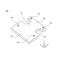
- FIG. 3 is a perspective view showing an example of the elastic body 21.
- the elastic body 21 is formed in a plate shape.
- the fixed end 21a of the elastic body 21 is provided with a fixing hole 21c for fixing the elastic body 21 to the second link 12 or the fixing member 22 with a screw or the like.
- the free end 21b of the elastic body 21 is provided with a fixing hole 21d for fixing the support member 24 to the elastic body 21 with a screw or the like.
- the elastic body 21 may have a constricted portion 21e between the fixed end 21a and the free end 21b.
- the constricted portion 21e may be formed in the deformation direction of the elastic body 21.
- the constricted portion 21e facilitates deformation of the elastic body 21 around the XYZ axis.
- the elastic body 21 passively deforms in the direction in which the striatum 20 wants to escape, secures a certain twisting distance of the striatum 20 to suppress the sudden twisting of the striatum 20, or the striatum 20. 20 The amount of twist is reduced.
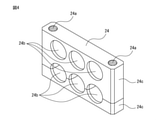
- FIG. 4 is a perspective view showing an example of the support member 24.
- the support member 24 is formed as a flat plate.
- the support member 24 is provided with a fixing hole 24a for fixing the support member 24 to the elastic body 21 with screws or the like.
- the support member 24 is provided with one or more support holes 24b for supporting the striatum 20. Since the striatum 20 can be easily inserted into the support hole 24b, the support member 24 may include two or more support pieces 24c that can be separated at the position of the support hole 24b.
- the support member 24 includes a plurality of support holes 24b, the plurality of support holes 24b may be arranged along one separation line.
- the support hole 24b should have an inner diameter slightly larger than the outer diameter of the striatum 20. As a result, the support member 24 can slidably support the striatum 20 while limiting the operating range of the striatum 20 to some extent. Further, the inner diameter of the support hole 24b may be the smallest at an intermediate position in the axial direction of the support hole 24b, and may have an inner peripheral surface that gradually increases toward both ends in the axial direction. As a result, the contact area between the striatum 20 and the inner peripheral surface of the support hole 24b can be reduced.
- the support member 24 itself is formed of a material having a low friction coefficient, for example, a fluororesin such as tetrafluoroethylene (polytetrafluoroethylene: PTFE), a polyolefin resin or the like.
- a fluororesin such as tetrafluoroethylene (polytetrafluoroethylene: PTFE), a polyolefin resin or the like.
- the inner peripheral surface of the support hole 24b may be coated with a material having a low coefficient of friction.
- the support member 24 suppresses the runaway of the striatum 20 in response to the rotation of the link, and prevents the striatum 20 from coming into contact with surrounding objects and wearing. Can be prevented. Further, since the support member 24 slidably supports the striatum 20, the load acting on the striatum 20 can be reduced according to the rotation of the link. Further, by reducing the friction coefficient of the support hole 24b, it is possible to suppress the wear of the striatum 20 due to the rubbing between the striatum 20 and the support member 24.
- the above configuration of the striatum support structure 2 is an example, and other forms can be adopted.
- the striatal support structure 2 may be applied not to the rotation shaft portion between the first link 11 and the second link 12, but to the rotation shaft portion between the second link 12 and the third link 13. .
- the striatum support structure 2 may be laid outside the robot 1 instead of being laid inside the robot 1.
- the striatal support structure 2 may be applied to a rotation shaft portion of another form of a robot, for example, a vertical articulated robot or a humanoid described later.
- the striatal support structure 2 may be applied to a rotating shaft portion of another machine such as a vehicle or an aircraft.
- the elastic body 21 may be fixed to both of the two links one by one, or may be fixed to only one link. Further, the elastic body 21 does not indirectly support the striatum 20 via the support member 24, but the elastic body 21 has a support hole for supporting the striatum 20, and the elastic body 21 itself is the striatum. 20 may be directly supported.
- FIG. 5A and 5B are VV cross-sectional views of the second link 12 showing an operation example of the elastic body 21.
- the striatum 20 is not drawn in these figures so that the operation of the elastic body 21 can be easily grasped.
- FIG. 5A shows a state in which the elastic body 21 is not deformed
- FIG. 5B shows a state in which the elastic body 21 is deformed in response to the rotation of the second link 12.
- the elastic body 21 passively deforms in the direction P'(for example, around the J1 axis) where the striatum 20 wants to escape, and the second link 12 turns in the reverse direction.
- the elastic body 21 passively deforms in the desired escape direction N'(for example, around the J1 axis) of the striatum 20.
- the elastic body 21 passively deforms in the direction in which the striatum 20 wants to escape in response to the rotation of the second link 12, and the striatum 20 secures a twisting distance of the striatum 20. Suppresses abrupt twisting or reduces the amount of twisting of the striatum 20. Further, by arranging the elastic body 21 between the two fixed positions by the fastener 23 (see FIG. 2), the twisted portion of the striatum 20 can be dispersed. As a result, the twist of the striatum 20 can be alleviated.
- the elastic body 21 limits the operating range of the striatum 20 to some extent, it is possible to prevent the striatum 20 from being worn due to contact between the striatum 20 and a peripheral object. As a result, the life of the striatum 20 is improved. By improving the life of the striatum 20, it becomes possible to adopt an inexpensive striatum that could not be adopted until now. In contrast, if the elastic body 21 is not provided, the striatum 20 is intensively and excessively twisted in the vicinity of the two fixed positions by the fastener 23. Further, due to the violence of the striatum 20, the striatum 20 comes into contact with a peripheral object and the striatum 20 is worn.
- FIG. 6 is a perspective view of the striatum support structure 2 applied to the robot 1 of another form.
- the robot 1 is, for example, a vertical articulated robot, and includes at least a first link 11, a second link 12, and a third link 13.
- the first link 11 is, for example, a hollow base
- the second link 12 and the third link 13 are, for example, hollow arm members.
- the first link 11 and the second link 12 are rotatably connected around the J1 axis
- the second link 12 and the third link 13 are rotatably connected around the J2 axis.
- the J1 axis and the J2 axis are perpendicular to each other.
- Actuators such as electric motors and speed reducers are provided on the J1 axis and the J2 axis, respectively, and cables such as signal lines and power lines are connected to the actuators.
- a tool such as a suction hand or a screwdriver is detachably attached to the tip of the robot, and a cable, an air tube, or the like is connected to the tool.
- the striatum 20 such as these cables and air tubes is laid, for example, extending from the inside of the first link 11 to the inside of the third link 13 through the outside of the second link 12 and the third link 13. Further, the striatum 20 is connected to a control device (not shown) that controls the robot 1 and the tool.
- the striatal support structure 2 of this example is applied to the rotation shaft portion between the second link 12 and the third link 13.
- the striatum support structure 2 is a striatum laid across the second link 12 and the third link 13 rotatably connected around the J2 axis, and the second link 12 and the third link 13. 20 and an elastic body 21 that is directly fixed to the third link 13 at a position away from the J2 axis and directly supports the striatum 20.
- the striatum 20 includes, for example, a cable, an air tube, and the like.
- the striatum 20 is fixed in a predetermined position to each of the second link 12 and the third link 13 by, for example, a fastener 23 (not shown) such as a binding band in order to prevent wear due to contact with a peripheral object. It is good.
- a fastener 23 such as a binding band
- the elastic body 21 is formed of an elastomer such as rubber.
- the elastic body 21 includes a fixed end 21a directly fixed to the third link 13 and a free end 21b that directly supports the striatum 20 at a position closer to the J2 axis than the fixed end 21a. It is good to be there.
- the fixed end 21a of the elastic body 21 is directly fixed to the third link 13, for example, with a screw or the like.
- a support member 24 that supports the striatum 20 is attached to the free end 21b of the elastic body 21, for example, with screws or the like.
- the support member 24 is, for example, a U-shaped or U-shaped fastener.
- the support member 24 is provided with a fixing hole 24a for fixing the support member 24 to the elastic body 21 with screws or the like.
- the support member 24 restrains the striatum 20 so that the striatum 20 does not operate, but the striatum 20 may be slidably supported.
- FIG. 7 is a perspective view showing an example of the elastic body 21.
- the elastic body 21 is formed in a plate shape.
- the fixed end 21a of the elastic body 21 is provided with a fixing hole 21c for fixing the elastic body 21 to the third link 13 with a screw or the like.
- the free end 21b of the elastic body 21 is provided with a fixing hole 21d for fixing the support member 24 to the elastic body 21 with a screw or the like.
- the elastic body 21 may have a constricted portion 21e between the fixed end 21a and the free end 21b.
- the constricted portion 21e may be formed in the deformation direction of the elastic body 21.
- the constricted portion 21e facilitates deformation of the elastic body 21 around the XYZ axis.
- the elastic body 21 passively deforms in the direction in which the striatum 20 wants to escape, secures a certain twisting distance of the striatum 20 to suppress the sudden twisting of the striatum 20, or the striatum 20. 20 The amount of twist is reduced.
- the elastic body 21 rotates in the direction in which the striatum 20 wants to escape (for example, around the J2 axis or in the figure). Passively transforms to the front side or the depth side of 6. In this way, the elastic body 21 passively deforms in the direction in which the striatum 20 wants to escape in response to the rotation of the third link 13, and the striatum 20 secures a twisting distance of the striatum 20. Suppresses abrupt twisting or reduces the amount of twisting of the striatum 20.
- the elastic body 21 limits the operating range of the striatum 20 to some extent, it is possible to prevent the striatum 20 from being worn due to contact between the striatum 20 and a peripheral object. As a result, the life of the striatum 20 is improved. By improving the life of the striatum 20, it becomes possible to adopt an inexpensive striatum that could not be adopted until now.
- FIG. 8 is a perspective view showing a modified example of the elastic body 21.
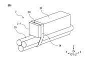
- the elastic body 21 of this example is different from the above-mentioned one in that it is a square bar body.
- the cross section of the elastic body 21 may be square, and in this case, the deformation of the elastic body 21 around the XYZ axes is facilitated. Further, in order to facilitate the deformation of the elastic body 21, it is preferable to arrange the elastic body 21 so that one surface 21f of the square bar body is parallel to the rotation axis between the two links.
- a support member 24 that supports the striatum 20 is attached to the free end of the elastic body 21.
- the support member 24 is a fastener such as a binding band.
- the support member 24 may restrain the striatum 20, but may slidably support the striatum 20.
- a material having a low friction coefficient for example, a fluororesin such as tetrafluoroethylene (polytetrafluoroethylene: PTFE) or a low friction tape such as a polyolefin resin is applied to the linear body 20. It is good to paste it.
- FIG. 9 is a perspective view showing another modified example of the elastic body 21.
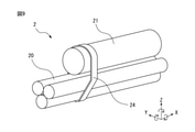
- the elastic body 21 of this example is a round bar body.
- the cross section of the elastic body 21 is preferably a perfect circle, which enables the elastic body 21 to be deformed around the XYZ axes.
- a support member 24 that supports the striatum 20 is attached to the free end of the elastic body 21.
- the support member 24 is a fastener such as a binding band.
- the support member 24 may restrain the striatum 20, but may slidably support the striatum 20.
- a material having a low friction coefficient for example, a fluororesin such as tetrafluoroethylene (polytetrafluoroethylene: PTFE) or a low friction tape such as a polyolefin resin is applied to the linear body 20. It is good to paste it.
- a fluororesin such as tetrafluoroethylene (polytetrafluoroethylene: PTFE) or a low friction tape such as a polyolefin resin is applied to the linear body 20. It is good to paste it.
- FIG. 10 is a perspective view showing another modified example of the elastic body 21.
- the elastic body 21 of this example is a square bar and has a constricted portion 21e between the fixed end 21a and the free end 21b.
- the constricted portion 21e may be formed in the deformation direction of the elastic body 21.
- the constricted portion 21e is formed on each of the four sides of the square bar.
- the constricted portion 21e facilitates deformation of the elastic body 21 around the XYZ axis.
- a support member 24 that supports the striatum 20 is attached to the free end 21b of the elastic body 21.
- the support member 24 is a fastener such as a binding band.
- the support member 24 may restrain the striatum 20, but may slidably support the striatum 20.
- a material having a low friction coefficient for example, a fluororesin such as tetrafluoroethylene (polytetrafluoroethylene: PTFE) or a low friction tape such as a polyolefin resin is applied to the linear body 20. It is good to paste it.
- FIG. 11 is a perspective view showing still another modified example of the elastic body 21.
- the elastic body 21 of this example is different from the above-mentioned one in that it is a coil spring.
- the coil spring is made of, for example, metal. By forming the elastic body 21 from metal, deterioration of the elastic body 21 can be suppressed.
- the coil spring allows the elastic body 21 to be deformed around the XYZ axis.
- a support member 24 that supports the striatum 20 is attached to the free end of the elastic body 21.
- the support member 24 is a fastener such as a binding band.
- the support member 24 may restrain the striatum 20, but may slidably support the striatum 20.
- a material having a low friction coefficient for example, a fluororesin such as tetrafluoroethylene (polytetrafluoroethylene: PTFE) or a low friction tape such as a polyolefin resin is applied to the linear body 20. It is good to paste it.
- a fluororesin such as tetrafluoroethylene (polytetrafluoroethylene: PTFE) or a low friction tape such as a polyolefin resin is applied to the linear body 20. It is good to paste it.
- FIG. 12 is a perspective view showing still another modified example of the elastic body 21.
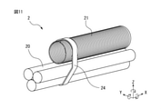
- the elastic body 21 of this example is a coil spring, and is different from the above-mentioned one in that the striatum 20 is inserted into the coil spring.
- the elastic body 21 may restrain the striatum 20, but may slidably support the striatum 20.
- the coil spring may have an inner diameter slightly larger than the outer diameter of the striatum 20.
- a material having a low friction coefficient for example, a fluororesin such as tetrafluoroethylene (polytetrafluoroethylene: PTFE) or a polyolefin resin or the like has a low friction. It is advisable to attach a tape.
- PTFE tetrafluoroethylene
- FIG. 13 is a perspective view showing still another modified example of the elastic body 21.
- the elastic body 21 of this example is different from the above-mentioned one in that it is a leaf spring.
- the leaf spring facilitates deformation of the elastic body 21 around one of the XYZ axes (for example, around the Z axis).
- a support member 24 that supports the striatum 20 is attached to the free end of the elastic body 21.
- the support member 24 is a fastener such as a binding band.
- the support member 24 may restrain the striatum 20, but may slidably support the striatum 20.
- a material having a low coefficient of friction such as a fluororesin such as tetrafluoroethylene (polytetrafluoroethylene: PTFE), a polyolefin resin, etc.
- a fluororesin such as tetrafluoroethylene (polytetrafluoroethylene: PTFE), a polyolefin resin, etc.
- PTFE polytetrafluoroethylene
- the flat plate support members 24 described with reference to FIG. 4 may be attached to both sides of the leaf spring to support the striatum 20.
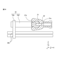
- FIG. 14 is a partial vertical sectional view showing another modification of the striatum support structure 2.
- the elastic body 21 is an elastomer such as rubber, and the fixed end 21a of the elastic body 21 is fixed to the fixing member 22 having a joint fossa, and the free end 21b of the elastic body 21 is fixed.
- a support member 24 having a joint head is attached.
- the fixing member 22 and the supporting member 24 are formed of, for example, metal, resin, or the like.
- the support member 24 may include, for example, a support piece 24d having a joint head and a support piece 24e attached to the support piece 24d to support the striatum 20.
- the support piece 24e may be, for example, a fastener such as a binding band, but may be a support member provided with the support hole 24b described with reference to FIG.
- the support member 24 may restrain the striatum 20, but may slidably support the striatum 20.
- the fixing member 22 may be provided with a joint head instead of a joint fossa, and the support member 24 may be provided with a joint fossa instead of the joint head.
- the support piece 24d may be an elastic body 21 such as an elastomer, and the fixing member 22 and the support member 24 may have a joystick-like connecting structure.
- the elastic body 21 passively deforms in the direction in which the striatum 20 wants to escape according to the rotation of the link, secures a twisting distance of the striatum 20, and secures the twisting distance of the striatum 20. Suppresses the abrupt twisting of 20 or reduces the amount of twisting of the striatum 20. As a result, the twist of the striatum 20 can be alleviated.
- the elastic body 21 limits the operating range of the striatum 20 to some extent, it is possible to prevent the striatum 20 from being worn due to contact between the striatum 20 and a peripheral object. As a result, the life of the striatum 20 is improved. By improving the life of the striatum 20, it becomes possible to adopt an inexpensive striatum that could not be adopted until now.
Landscapes
- Engineering & Computer Science (AREA)
- Robotics (AREA)
- Mechanical Engineering (AREA)
- Manipulator (AREA)
Abstract
線条体支持構造は、所定の軸線回りに回動可能に連結された2つのリンクと、2つのリンクに掛け渡して敷設された線条体と、軸線から離れた位置で2つのリンクの少なくとも一方に直接的又は間接的に固定されていて線条体を直接的又は間接的に支持する弾性体と、を備える。
Description
本発明は、線条体支持構造及びロボットに関し、特に線条体の捻じれを緩和する線条体支持構造及びロボットに関する。
産業用ロボット等では、信号線や動力線を収納したケーブルやエアチューブ等の長尺の線条体が敷設されている。従来のロボット関節部における線条体フォーミングでは、回転に伴う線条体の捻じれや、線条体と周辺部材との間の擦れによる摩耗等により長期寿命を確保することが困難になることがあった。また、昨今求められているロボット動作の高速化に伴い、線条体内の線材の配置方法、材質、及び線条体のクランプ間距離等の検討に工数やコストが掛かっている。本願に関連する技術としては、後述の文献が公知である。
特許文献1には、産業用ロボットにおける2つの相対旋回部材内に配線されるケーブルを保護、保持するケーブル処理装置が開示されている。ケーブル処理装置は、2つの相対旋回部材の少なくとも一方の内部に相対旋回部材の長さ方向に対して交差する横向きに取付けられた摺動軸と、ケーブルを把持すると共に摺動軸上を摺動するクランプ部材と、を備えており、摺動軸は相対旋回部材の旋回中心を中心とした略円周上でクランプ部材を摺動自在に保持するため、相対旋回部材の旋回作用に伴うケーブルの捻じれが解消される。
特許文献2には、関節軸回りに旋回可能に連結された第1フレーム及び第2フレームを有するロボットアームと、第1フレーム及び第2フレームの側面に沿って配置されたケーブルと、ケーブルを第1フレームの側面に固定する第1固定部材と、ケーブルを第2フレームの側面に固定する第2固定部材と、ケーブルの第1固定部材と第2固定部材との間の部分を保持する保持部材と、保持部材が関節軸の軸方向へ移動するのを規制し、且つ保持部材がケーブルの屈曲動作に追従して関節軸の軸方向と直交する方向へ移動可能に保持部材を支持する支持機構と、を備えるロボットが記載されている。
本発明は、従来の問題点に鑑み、回転軸部における線条体の捻じれを緩和することを目的とする。
本開示の一態様は、所定の軸線回りに回動可能に連結された2つのリンクと、2つのリンクに掛け渡して敷設された線条体と、軸線から離れた位置で2つのリンクの少なくとも一方に直接的又は間接的に取付けられていて線条体を直接的又は間接的に支持する弾性体と、を備える、線条体支持構造を提供する。
本開示の一態様によれば、弾性体が、リンクの回動に応じて線条体の逃げたい方向に受動的に変形し、線条体の捻じれる距離を確保して線条体が急激に捻じれるのを抑制する又は線条体の捻じれ量を低減する。これにより、線条体の捻じれを緩和できる。一方、弾性体は、線条体の動作範囲をある程度制限するため、線条体と周辺物体との接触による線条体の摩耗も防止できる。ひいては線条体の寿命が向上する。線条体の寿命の向上によって今まで採用できなかった廉価な線条体の採用も可能になる。
以下、添付図面を参照して本開示の実施形態を詳細に説明する。各図面において、同一又は類似の構成要素には同一又は類似の符号が付与されている。また、以下に記載する実施形態は特許請求の範囲に記載される発明の技術的範囲及び用語の意義を限定するものではない。なお、本書において用語「直接的」とは直接接触した状態を意味し、用語「間接的」とは他の構成要素を介して間接接触した状態を意味することに留意されたい。
図1は本実施形態の線条体支持構造を備えたロボット1の斜視図である。ロボット1は、例えば水平多関節ロボット(スカラロボット)であり、第一リンク11と、第二リンク12と、第三リンク13と、先端軸14と、を備えている。第一リンク11は例えば中空のベースであり、第二リンク12及び第三リンク13は例えば中空のアーム部材であり、先端軸14は例えば中空のボールねじスプラインである。第一リンク11と第二リンク12はJ1軸線回りに回動可能に連結され、第二リンク12と第三リンク13はJ2軸線回りに回動可能に連結される。第三リンク13と先端軸14はJ3軸線に沿って上下運動可能に連結されると共にJ4軸線回りに回動可能に連結される。J1~J4軸線は互いに平行である。J1~J4軸線には例えば電動機や減速機等のアクチュエータ(図示せず)が夫々配設され、アクチュエータには信号線や動力線等のケーブルが接続される。先端軸14には例えば吸着ハンド、ドライバ等のツール(図示せず)が着脱可能に取付けられ、ツールにはケーブルやエアチューブ等が接続される。これらケーブルやエアチューブ等の線条体(図2参照)は、周囲物体や人との接触を回避するため、例えば第一リンク11、第二リンク12、第三リンク13、先端軸14、ツール等の内部に掛け渡して敷設されるとよい。また、線条体はロボット1やツールを制御する制御装置(図示せず)に接続される。本書では、第一リンク11、第二リンク12、第三リンク13、先端軸14、ツール等の回転軸部を構成する部材を「リンク」と称する。
図2は第二リンク12のII-II断面図である。線条体支持構造2は2つのリンク間の回転軸部に適用される。例えば線条体支持構造2は、J1軸線回りに回動可能に連結された第一リンク11(図1参照)及び第二リンク12と、第一リンク11と第二リンク12に掛け渡して敷設された線条体20と、J1軸線から離れた位置で第二リンク12に間接的に固定されていて線条体20を間接的に支持する弾性体21と、を備えている。
線条体20は、例えばケーブル20a、エアチューブ20b等を備えている。線条体20は、周辺部材との接触による摩耗を防止するため、例えば結束バンド等の留め具23によって第一リンク11及び第二リンク12の各々に所定の位置で固定されるとよい。これら2つの固定位置の間に、線条体20を直接的又は間接的に支持する弾性体21を配置することにより、線条体20の捻じれる箇所を分散できる。
弾性体21は、例えばゴム等のエラストマーで形成される。弾性体21は、第二リンク12に間接的に固定される固定端21aと、固定端21aよりもJ1軸線に近い位置で線条体20を間接的に支持する自由端21bと、を備えているとよい。弾性体21の固定端21aは、例えば板金等の固定部材22にねじ等で固定されて固定部材22を介して第二リンク12に固定されているが、第二リンク12に直接的に固定されてもよい。弾性体21の自由端21bは、例えば線条体20を支持する支持部材24がねじ等で取付けられているが、弾性体21が線条体20を直接的に支持してもよい。支持部材24は、線条体20の動作範囲をある程度制限しつつ線条体20を摺動可能に支持することが好ましいが、線条体20が動作しないように線条体20を拘束してもよい。
図3は弾性体21の一例を示す斜視図である。例えば弾性体21は板状に形成される。弾性体21の固定端21aは弾性体21を第二リンク12又は固定部材22にねじ等で固定する固定孔21cを備えている。弾性体21の自由端21bは支持部材24を弾性体21にねじ等で固定する固定孔21dを備えている。また、弾性体21は固定端21aと自由端21bとの間にくびれ部分21eを備えているとよい。くびれ部分21eは弾性体21の変形方向に形成されているとよい。くびれ部分21eはXYZ軸回りの弾性体21の変形を容易にする。弾性体21は、線条体20の逃げたい方向に受動的に変形し、線条体20の捻じれる距離をある程度確保して線条体20が急激に捻じれるのを抑制する又は線条体20の捻じれ量を低減する。
図4は支持部材24の一例を示す斜視図である。例えば支持部材24は平板として形成される。支持部材24は支持部材24を弾性体21にねじ等で固定する固定孔24aを備えている。また、支持部材24は線条体20を支持する1つ又は複数の支持孔24bを備えている。線条体20を支持孔24bに挿通し易くため、支持部材24は支持孔24bの位置で分離可能な2つ以上の支持片24cを備えていてもよい。支持部材24が複数の支持孔24bを備える場合、複数の支持孔24bを一つの分離線に沿って配列するとよい。
支持孔24bは線条体20の外径よりも若干大きい内径を有しているとよい。これにより、支持部材24は線条体20の動作範囲をある程度制限しつつ線条体20を摺動可能に支持できる。また、支持孔24bの内径は、支持孔24bの軸方向の途中位置で最も小さく、軸方向両端に向かって次第に増大する内周面を有していてもよい。これにより、線条体20と支持孔24bの内周面との接触面積を低減できる。さらに、支持孔24bの摩擦係数を低減するため、支持部材24自体を、低摩擦係数の素材、例えば4フッ化エチレン(ポリテトラフルオロエチレン:PTFE)等のフッ素樹脂やポリオレフィン系樹脂等で形成してもよいし、又は支持孔24bの内周面を低摩擦係数の素材でコーティングしてもよい。
支持部材24が線条体20の動作範囲をある程度制限することにより、リンクの回動に応じた線条体20の暴れを抑制して線条体20が周辺物体に接触して摩耗するのを防止できる。また、支持部材24が線条体20を摺動可能に支持することにより、リンクの回動に応じて線条体20に作用する負荷を低減できる。さらに、支持孔24bの摩擦係数を低減することにより、線条体20と支持部材24との間の擦れによる線条体20の摩耗も抑制できる。
線条体支持構造2の上記構成は、一例であり、他の形態も採用できることに留意されたい。例えば線条体支持構造2は、第一リンク11と第二リンク12との間の回転軸部ではなく、第二リンク12と第三リンク13との間の回転軸部に適用してもよい。また、線条体支持構造2は、ロボット1の内部に敷設するのではなく、ロボット1の外部に敷設してもよい。さらに、線条体支持構造2は、他の形態のロボット、例えば後述の垂直多関節ロボットやヒューマノイド等の回転軸部に適用してもよい。或いは、線条体支持構造2は、他の機械、例えば車両、航空機等の回転軸部に適用してもよい。また、弾性体21は2つのリンクの双方に一つずつ固定してもよいし又は一つのリンクにのみ固定してもよい。さらに、弾性体21は支持部材24を介して線条体20を間接的に支持するのではなく、弾性体21が線条体20を支持する支持孔を備え、弾性体21自体が線条体20を直接的に支持してもよい。
図5A及び図5Bは弾性体21の動作例を示す第二リンク12のV-V断面図である。弾性体21の動作を容易に把握できるように、これら図では線条体20を描画していないことに留意されたい。図5Aは弾性体21が変形していない様子を示しており、図5Bは第二リンク12の回動に応じて弾性体21が変形した様子を示している。例えば第二リンク12が正転方向Pに回転した場合は、弾性体21が線条体20の逃げたい方向P’(例えばJ1軸線回り)に受動的に変形し、第二リンク12が逆転方向Nに回転した場合は、弾性体21が線条体20の逃げたい方向N’(例えばJ1軸線回り)に受動的に変形する。
このように弾性体21は、第二リンク12の回動に応じて線条体20の逃げたい方向に受動的に変形し、線条体20の捻じれる距離を確保して線条体20が急激に捻じれるのを抑制する又は線条体20の捻じれ量を低減する。また、留め具23(図2参照)による2つの固定位置の間に弾性体21を配置することにより、線条体20の捻じれる箇所を分散できる。これにより、線条体20の捻じれを緩和できる。一方、弾性体21は、線条体20の動作範囲をある程度制限するため、線条体20と周辺物体との接触による線条体20の摩耗も防止できる。ひいては線条体20の寿命が向上する。線条体20の寿命の向上によって今まで採用できなかった廉価な線条体の採用も可能になる。対照的に、弾性体21を設けない場合は、線条体20が留め具23による2つの固定位置の近傍で集中的に過大に捻じれてしまう。また、線条体20の暴れによって線条体20が周辺物体と接触して線条体20が摩耗してしまう。
図6は他の形態のロボット1に適用した線条体支持構造2の斜視図である。ロボット1は、例えば垂直多関節ロボットであり、第一リンク11と、第二リンク12と、第三リンク13と、を少なくとも備えている。第一リンク11は例えば中空のベースであり、第二リンク12及び第三リンク13は例えば中空のアーム部材である。第一リンク11と第二リンク12はJ1軸線回りに回動可能に連結され、第二リンク12と第三リンク13はJ2軸線回りに回動可能に連結される。J1軸線とJ2軸線は互いに垂直である。J1軸線とJ2軸線には例えば電動機や減速機等のアクチュエータが夫々設けられ、アクチュエータには信号線や動力線等のケーブルが接続される。また、ロボット先端には例えば吸着ハンド、ドライバ等のツール(図示せず)が着脱可能に取付けられ、ツールにはケーブルやエアチューブ等が接続される。これらケーブルやエアチューブ等の線条体20は、例えば第一リンク11の内部から第二リンク12と第三リンク13の外部を通って第三リンク13の内部に掛け渡して敷設される。また、線条体20はロボット1やツールを制御する制御装置(図示せず)に接続される。
本例の線条体支持構造2は第二リンク12と第三リンク13との間の回転軸部に適用される。例えば線条体支持構造2は、J2軸線回りに回動可能に連結された第二リンク12及び第三リンク13と、第二リンク12と第三リンク13に掛け渡して敷設された線条体20と、J2軸線から離れた位置で第三リンク13に直接的に固定されていて線条体20を直接的に支持する弾性体21と、を備えている。
線条体20は、例えばケーブル、エアチューブ等を備えている。線条体20は、周辺物体との接触による摩耗を防止するため、例えば結束バンド等の留め具23(図示せず)によって第二リンク12及び第三リンク13の各々に所定の位置で固定されるとよい。これら2つの固定位置の間に、線条体20を直接的又は間接的に支持する弾性体21を配置することにより、線条体20の捻じれる箇所を分散できる。
弾性体21は、例えばゴム等のエラストマーで形成される。弾性体21は、第三リンク13に直接的に固定される固定端21aと、固定端21aよりもJ2軸線に近い位置で線条体20を直接的に支持する自由端21bと、を備えているとよい。弾性体21の固定端21aは、例えば第三リンク13にねじ等で直接的に固定されている。弾性体21の自由端21bは、例えば線条体20を支持する支持部材24がねじ等で取付けられている。
支持部材24は、例えばコの字形状又はU字形状の留め具である。支持部材24は支持部材24を弾性体21にねじ等で固定する固定孔24aを備えている。支持部材24は、線条体20が動作しないように線条体20を拘束するが、線条体20を摺動可能に支持してもよい。
図7は弾性体21の一例を示す斜視図である。例えば弾性体21は板状に形成される。弾性体21の固定端21aは弾性体21を第三リンク13にねじ等で固定する固定孔21cを備えている。弾性体21の自由端21bは支持部材24を弾性体21にねじ等で固定する固定孔21dを備えている。また、弾性体21は固定端21aと自由端21bとの間にくびれ部分21eを備えているとよい。くびれ部分21eは弾性体21の変形方向に形成されているとよい。くびれ部分21eはXYZ軸回りの弾性体21の変形を容易にする。弾性体21は、線条体20の逃げたい方向に受動的に変形し、線条体20の捻じれる距離をある程度確保して線条体20が急激に捻じれるのを抑制する又は線条体20の捻じれ量を低減する。
図6を再び参照すると、例えば第三リンク13が正転方向Pに回転した場合や逆転方向Nに回転した場合は、弾性体21が線条体20の逃げたい方向(例えばJ2軸線回りや図6の手前側又は奥行側)に受動的に変形する。このように弾性体21は、第三リンク13の回動に応じて線条体20の逃げたい方向に受動的に変形し、線条体20の捻じれる距離を確保して線条体20が急激に捻じれるのを抑制する又は線条体20の捻じれ量を低減する。また、留め具23による2つの固定位置の間に弾性体21を配置することにより、線条体20の捻じれる箇所を分散できる。これにより、線条体20の捻じれを緩和できる。一方、弾性体21は、線条体20の動作範囲をある程度制限するため、線条体20と周辺物体との接触による線条体20の摩耗も防止できる。ひいては線条体20の寿命が向上する。線条体20の寿命の向上によって今まで採用できなかった廉価な線条体の採用も可能になる。
図8は弾性体21の変形例を示す斜視図である。本例の弾性体21は角棒体である点で、前述のものとは異なる。弾性体21の横断面は、正方形であるとよく、この場合、XYZ軸回りの弾性体21の変形を容易にする。さらに弾性体21の変形を容易にするため、角棒体の一つの面21fが2つのリンク間の回転軸線と平行になるように弾性体21を配置するとよい。弾性体21の自由端は線条体20を支持する支持部材24が取付けられる。支持部材24は例えば結束バンド等の留め具である。支持部材24は、線条体20を拘束してもよいが、線条体20を摺動可能に支持するとよい。線条体20の摩擦係数を低減するため、線条体20に低摩擦係数の素材、例えば4フッ化エチレン(ポリテトラフルオロエチレン:PTFE)等のフッ素樹脂やポリオレフィン系樹脂等の低摩擦テープを貼付するとよい。
図9は弾性体21の他の変形例を示す斜視図である。本例の弾性体21は丸棒体である。弾性体21の横断面は、正円形であるとよく、弾性体21のXYZ軸回りの変形を可能にする。弾性体21の自由端は線条体20を支持する支持部材24が取付けられる。支持部材24は例えば結束バンド等の留め具である。支持部材24は、線条体20を拘束してもよいが、線条体20を摺動可能に支持するとよい。線条体20の摩擦係数を低減するため、線条体20に低摩擦係数の素材、例えば4フッ化エチレン(ポリテトラフルオロエチレン:PTFE)等のフッ素樹脂やポリオレフィン系樹脂等の低摩擦テープを貼付するとよい。
図10は弾性体21の別の変形例を示す斜視図である。本例の弾性体21は、角棒体であり、且つ固定端21aと自由端21bとの間にくびれ部分21eを備えている。くびれ部分21eは弾性体21の変形方向に形成されているとよい。この例では、くびれ部分21eが角棒体の四面の各々に形成されている。くびれ部分21eはXYZ軸回りの弾性体21の変形を容易にする。弾性体21の自由端21bは線条体20を支持する支持部材24が取付けられる。支持部材24は例えば結束バンド等の留め具である。支持部材24は、線条体20を拘束してもよいが、線条体20を摺動可能に支持するとよい。線条体20の摩擦係数を低減するため、線条体20に低摩擦係数の素材、例えば4フッ化エチレン(ポリテトラフルオロエチレン:PTFE)等のフッ素樹脂やポリオレフィン系樹脂等の低摩擦テープを貼付するとよい。
図11は弾性体21のさらに別の変形例を示す斜視図である。本例の弾性体21はコイルばねである点で、前述のものとは異なる。コイルばねは例えば金属等で形成される。弾性体21を金属で形成することで弾性体21の劣化を抑制できる。コイルばねはXYZ軸回りの弾性体21の変形を可能にする。弾性体21の自由端は線条体20を支持する支持部材24が取付けられる。支持部材24は例えば結束バンド等の留め具である。支持部材24は、線条体20を拘束してもよいが、線条体20を摺動可能に支持するとよい。線条体20の摩擦係数を低減するため、線条体20に低摩擦係数の素材、例えば4フッ化エチレン(ポリテトラフルオロエチレン:PTFE)等のフッ素樹脂やポリオレフィン系樹脂等の低摩擦テープを貼付するとよい。
図12は弾性体21のさらに別の変形例を示す斜視図である。本例の弾性体21はコイルばねであり、線条体20がコイルばねの中に挿通される点で、前述のものとは異なる。弾性体21は、線条体20を拘束してもよいが、線条体20を摺動可能に支持するとよい。例えばコイルばねは線条体20の外径よりも若干大きい内径を有しているとよい。また、線条体20の摩擦係数を低減するため、線条体20に低摩擦係数の素材、例えば4フッ化エチレン(ポリテトラフルオロエチレン:PTFE)等のフッ素樹脂やポリオレフィン系樹脂等の低摩擦テープを貼付するとよい。
図13は弾性体21のさらに別の変形例を示す斜視図である。本例の弾性体21は板ばねである点で、前述のものとは異なる。板ばねはXYZ軸のうちの一軸回り(例えばZ軸回り)の弾性体21の変形を容易にする。弾性体21の変形を容易にするため、板ばねの面が2つのリンク間の回転軸線と平行になるように弾性体21を配置するとよい。弾性体21の自由端は線条体20を支持する支持部材24が取付けられる。支持部材24は例えば結束バンド等の留め具である。支持部材24は、線条体20を拘束してもよいが、線条体20を摺動可能に支持するとよい。線条体20の摩擦係数を低減するため、線条体20又は弾性体21に低摩擦係数の素材、例えば4フッ化エチレン(ポリテトラフルオロエチレン:PTFE)等のフッ素樹脂やポリオレフィン系樹脂等の低摩擦テープを貼付するとよい。或いは、図4を参照して説明した平板の支持部材24を板ばねの両側に取付けて線条体20を支持してもよい。
図14は線条体支持構造2の別の変形例を示す部分縦断面図である。本例の線条体支持構造2では、弾性体21が例えばゴム等のエラストマーであり、弾性体21の固定端21aは関節窩を備えた固定部材22に固定され、弾性体21の自由端21bは関節頭を備えた支持部材24が取付けられる点で、前述のものとは異なる。固定部材22及び支持部材24は例えば金属、樹脂等で形成される。支持部材24の関節頭が固定部材22の関節窩の中で回動すると、弾性体21の復元力によって支持部材24が基準位置(図14の位置)に復帰する。支持部材24は、例えば関節頭を備えた支持片24dと、支持片24dに取付けられていて線条体20を支持する支持片24eと、を備えているとよい。支持片24eは、例えば結束バンド等の留め具でよいが、図4を参照して説明した支持孔24bを備えた支持部材でもよい。支持部材24は、線条体20を拘束してもよいが、線条体20を摺動可能に支持するとよい。なお、固定部材22が関節窩ではなく関節頭を備え、支持部材24が関節頭ではなく関節窩を備えていてもよい。或いは、支持片24dがエラストマー等の弾性体21であり、固定部材22と支持部材24がジョイスティック状の連結構造を備えていてもよい。
以上の実施形態によれば、弾性体21は、リンクの回動に応じて線条体20の逃げたい方向に受動的に変形し、線条体20の捻じれる距離を確保して線条体20が急激に捻じれるのを抑制する又は線条体20の捻じれ量を低減する。これにより、線条体20の捻じれを緩和できる。一方、弾性体21は、線条体20の動作範囲をある程度制限するため、線条体20と周辺物体との接触による線条体20の摩耗も防止できる。ひいては線条体20の寿命が向上する。線条体20の寿命の向上によって今まで採用できなかった廉価な線条体の採用も可能になる。
本明細書において種々の実施形態について説明したが、本発明は、前述の実施形態に限定されるものではなく、特許請求の範囲に記載された範囲内において種々の変更を行えることを認識されたい。
1 ロボット
2 線条体支持構造
11 第一リンク
12 第二リンク
13 第三リンク
14 先端軸
20 線条体
20a ケーブル
20b エアチューブ
21 弾性体
21a 固定端
21b 自由端
21c~21d 固定孔
21e くびれ部分
21f 面
22 固定部材
23 留め具
24 支持部材
24a 固定孔
24b 支持孔
24c~24e 支持片
J1~J4 軸線
P 正転方向
N 逆転方向
P’、N’ 線条体の逃げたい方向
2 線条体支持構造
11 第一リンク
12 第二リンク
13 第三リンク
14 先端軸
20 線条体
20a ケーブル
20b エアチューブ
21 弾性体
21a 固定端
21b 自由端
21c~21d 固定孔
21e くびれ部分
21f 面
22 固定部材
23 留め具
24 支持部材
24a 固定孔
24b 支持孔
24c~24e 支持片
J1~J4 軸線
P 正転方向
N 逆転方向
P’、N’ 線条体の逃げたい方向
Claims (9)
- 所定の軸線回りに回動可能に連結された2つのリンクと、
前記2つのリンクに掛け渡して敷設された線条体と、
前記軸線から離れた位置で前記2つのリンクの少なくとも一方に直接的又は間接的に固定されていて前記線条体を直接的又は間接的に支持する弾性体と、
を備える、線条体支持構造。 - 前記弾性体は、前記リンクに直接的又は間接的に固定される固定端と、前記固定端よりも前記軸線に近い位置で前記線条体を直接的又は間接的に支持する自由端と、を有する、請求項1に記載の線条体支持構造。
- 前記弾性体は前記固定端と前記自由端との間にくびれ部分を備える、請求項2に記載の線条体支持構造。
- 前記自由端は前記線条体を支持する支持部材が取付けられている、請求項2又は3に記載の線条体支持構造。
- 前記支持部材及び前記弾性体の少なくとも一方は、前記線条体を拘束する、又は前記線条体の動作範囲を制限しつつ摺動可能に支持する、請求項4に記載の線条体支持構造。
- 前記弾性体は、エラストマー、コイルばね、又は板ばねである、請求項1から5のいずれか一項に記載の線条体支持構造。
- 前記弾性体はコイルばねであり、前記線条体が前記コイルばねの中に挿通されている、請求項1又は2に記載の線条体支持構造。
- 前記線条体は前記2つのリンクの各々に所定の位置で固定され、2つの固定位置の間に前記弾性体を配置した、請求項1から7のいずれか一項に記載の線条体支持構造。
- 請求項1から8のいずれか一項に記載の線条体支持構造を備えたロボット。
Priority Applications (4)
| Application Number | Priority Date | Filing Date | Title |
|---|---|---|---|
| JP2022547632A JP7590442B2 (ja) | 2020-09-14 | 2021-09-08 | 線条体支持構造及びロボット |
| DE112021003809.5T DE112021003809T5 (de) | 2020-09-14 | 2021-09-08 | Linearkörper-stützstruktur und roboter |
| CN202180061570.XA CN116075401A (zh) | 2020-09-14 | 2021-09-08 | 线条体支承构造和机器人 |
| US18/043,539 US20230264346A1 (en) | 2020-09-14 | 2021-09-08 | Linear body supporting structure and robot |
Applications Claiming Priority (2)
| Application Number | Priority Date | Filing Date | Title |
|---|---|---|---|
| JP2020153918 | 2020-09-14 | ||
| JP2020-153918 | 2020-09-14 |
Publications (1)
| Publication Number | Publication Date |
|---|---|
| WO2022054844A1 true WO2022054844A1 (ja) | 2022-03-17 |
Family
ID=80631556
Family Applications (1)
| Application Number | Title | Priority Date | Filing Date |
|---|---|---|---|
| PCT/JP2021/033043 Ceased WO2022054844A1 (ja) | 2020-09-14 | 2021-09-08 | 線条体支持構造及びロボット |
Country Status (5)
| Country | Link |
|---|---|
| US (1) | US20230264346A1 (ja) |
| JP (1) | JP7590442B2 (ja) |
| CN (1) | CN116075401A (ja) |
| DE (1) | DE112021003809T5 (ja) |
| WO (1) | WO2022054844A1 (ja) |
Citations (3)
| Publication number | Priority date | Publication date | Assignee | Title |
|---|---|---|---|---|
| JP2006007409A (ja) * | 2004-05-21 | 2006-01-12 | Fanuc Ltd | 産業用ロボットの線条体処理構造 |
| JP2007021636A (ja) * | 2005-07-14 | 2007-02-01 | Fanuc Ltd | 産業用ロボットの線条体処理構造 |
| JP2009531189A (ja) * | 2006-03-28 | 2009-09-03 | スル チョイ,グァン | 産業用ロボットのケーブル調節装置 |
Family Cites Families (6)
| Publication number | Priority date | Publication date | Assignee | Title |
|---|---|---|---|---|
| JP2559807B2 (ja) | 1988-06-01 | 1996-12-04 | ファナック株式会社 | 産業用ロボットの関節部におけるケーブル処理装置 |
| JPH08197482A (ja) * | 1995-01-19 | 1996-08-06 | Fanuc Ltd | 産業用ロボットのケーブル処理装置 |
| JP4837117B2 (ja) * | 2010-04-14 | 2011-12-14 | ファナック株式会社 | ロボットアーム部の線条体配設機構 |
| JP6184161B2 (ja) | 2012-07-12 | 2017-08-23 | キヤノン株式会社 | ロボット |
| SE542265C2 (en) * | 2017-03-06 | 2020-03-31 | Robotautomation Svenska Ab | An industrial robot and a device for transferring media from the robot to a tool |
| DE202018101572U1 (de) * | 2018-03-21 | 2019-06-24 | Kuka Deutschland Gmbh | Kabelhaltebaugruppe und Roboter |
-
2021
- 2021-09-08 US US18/043,539 patent/US20230264346A1/en not_active Abandoned
- 2021-09-08 JP JP2022547632A patent/JP7590442B2/ja active Active
- 2021-09-08 WO PCT/JP2021/033043 patent/WO2022054844A1/ja not_active Ceased
- 2021-09-08 DE DE112021003809.5T patent/DE112021003809T5/de active Pending
- 2021-09-08 CN CN202180061570.XA patent/CN116075401A/zh active Pending
Patent Citations (3)
| Publication number | Priority date | Publication date | Assignee | Title |
|---|---|---|---|---|
| JP2006007409A (ja) * | 2004-05-21 | 2006-01-12 | Fanuc Ltd | 産業用ロボットの線条体処理構造 |
| JP2007021636A (ja) * | 2005-07-14 | 2007-02-01 | Fanuc Ltd | 産業用ロボットの線条体処理構造 |
| JP2009531189A (ja) * | 2006-03-28 | 2009-09-03 | スル チョイ,グァン | 産業用ロボットのケーブル調節装置 |
Also Published As
| Publication number | Publication date |
|---|---|
| JPWO2022054844A1 (ja) | 2022-03-17 |
| DE112021003809T5 (de) | 2023-07-20 |
| JP7590442B2 (ja) | 2024-11-26 |
| CN116075401A (zh) | 2023-05-05 |
| US20230264346A1 (en) | 2023-08-24 |
Similar Documents
| Publication | Publication Date | Title |
|---|---|---|
| EP1743748B1 (en) | Guiding structure comprising a flexible tabular guide member for an umbilical member of an industrial robot | |
| US9289898B2 (en) | Horizontal multi-joint robot and robot | |
| EP1568449B1 (en) | Robot arm provided with a cable arrangement, and industrial robot utilizing the same | |
| CN1142375C (zh) | 能量供应链 | |
| US10960534B2 (en) | Robot and parallel link robot | |
| EP1892064A1 (en) | Drive mechanism for industrial robot arm | |
| WO2023107501A1 (en) | Humanoid robot | |
| JP6104701B2 (ja) | リンク作動装置 | |
| JP6511939B2 (ja) | ロボット | |
| WO2018143055A1 (ja) | 多関節溶接ロボット | |
| US10682756B1 (en) | Driving assembly and robotic hand having the same | |
| JP2009248287A (ja) | パラレルメカニズム | |
| WO2021005968A1 (ja) | 天吊り式の産業用ロボット | |
| JP5151514B2 (ja) | 線条体案内機構を備えた産業用ロボット | |
| US10149694B2 (en) | Energy balance mechanism for flexure joint | |
| JP7623505B2 (ja) | 線条体固定構造、機械、ロボット、及びアクチュエータ | |
| WO2022054844A1 (ja) | 線条体支持構造及びロボット | |
| JP7498611B2 (ja) | 関節機能部 | |
| JP5954706B2 (ja) | 関節装置及びリンク機構 | |
| CN119017415A (zh) | 手指结构总成、机械手 | |
| JP6539233B2 (ja) | 旋回機構及び位置決め装置 | |
| CN114986543B (zh) | 机械手 | |
| JP4805301B2 (ja) | パラレルメカニズム | |
| JP7829915B2 (ja) | ワイヤ駆動機構 | |
| CN108367430A (zh) | 机器人手臂机构 |
Legal Events
| Date | Code | Title | Description |
|---|---|---|---|
| 121 | Ep: the epo has been informed by wipo that ep was designated in this application |
Ref document number: 21866803 Country of ref document: EP Kind code of ref document: A1 |
|
| ENP | Entry into the national phase |
Ref document number: 2022547632 Country of ref document: JP Kind code of ref document: A |
|
| 122 | Ep: pct application non-entry in european phase |
Ref document number: 21866803 Country of ref document: EP Kind code of ref document: A1 |