WO2022054720A1 - 発熱フィルムの製造方法、発熱フィルム、レンズおよび車載カメラ - Google Patents
発熱フィルムの製造方法、発熱フィルム、レンズおよび車載カメラ Download PDFInfo
- Publication number
- WO2022054720A1 WO2022054720A1 PCT/JP2021/032499 JP2021032499W WO2022054720A1 WO 2022054720 A1 WO2022054720 A1 WO 2022054720A1 JP 2021032499 W JP2021032499 W JP 2021032499W WO 2022054720 A1 WO2022054720 A1 WO 2022054720A1
- Authority
- WO
- WIPO (PCT)
- Prior art keywords
- heat
- generating film
- generating
- film
- film according
- Prior art date
- Legal status (The legal status is an assumption and is not a legal conclusion. Google has not performed a legal analysis and makes no representation as to the accuracy of the status listed.)
- Ceased
Links
Images












Classifications
-
- G—PHYSICS
- G02—OPTICS
- G02B—OPTICAL ELEMENTS, SYSTEMS OR APPARATUS
- G02B1/00—Optical elements characterised by the material of which they are made; Optical coatings for optical elements
- G02B1/10—Optical coatings produced by application to, or surface treatment of, optical elements
- G02B1/12—Optical coatings produced by application to, or surface treatment of, optical elements by surface treatment, e.g. by irradiation
-
- G—PHYSICS
- G02—OPTICS
- G02B—OPTICAL ELEMENTS, SYSTEMS OR APPARATUS
- G02B7/00—Mountings, adjusting means, or light-tight connections, for optical elements
- G02B7/02—Mountings, adjusting means, or light-tight connections, for optical elements for lenses
- G02B7/021—Mountings, adjusting means, or light-tight connections, for optical elements for lenses for more than one lens
-
- G—PHYSICS
- G02—OPTICS
- G02B—OPTICAL ELEMENTS, SYSTEMS OR APPARATUS
- G02B1/00—Optical elements characterised by the material of which they are made; Optical coatings for optical elements
- G02B1/04—Optical elements characterised by the material of which they are made; Optical coatings for optical elements made of organic materials, e.g. plastics
- G02B1/041—Lenses
-
- G—PHYSICS
- G02—OPTICS
- G02B—OPTICAL ELEMENTS, SYSTEMS OR APPARATUS
- G02B27/00—Optical systems or apparatus not provided for by any of the groups G02B1/00 - G02B26/00, G02B30/00
- G02B27/0006—Optical systems or apparatus not provided for by any of the groups G02B1/00 - G02B26/00, G02B30/00 with means to keep optical surfaces clean, e.g. by preventing or removing dirt, stains, contamination, condensation
-
- G—PHYSICS
- G02—OPTICS
- G02B—OPTICAL ELEMENTS, SYSTEMS OR APPARATUS
- G02B27/00—Optical systems or apparatus not provided for by any of the groups G02B1/00 - G02B26/00, G02B30/00
- G02B27/02—Viewing or reading apparatus
- G02B27/028—Viewing or reading apparatus characterised by the supporting structure
-
- G—PHYSICS
- G02—OPTICS
- G02B—OPTICAL ELEMENTS, SYSTEMS OR APPARATUS
- G02B7/00—Mountings, adjusting means, or light-tight connections, for optical elements
- G02B7/02—Mountings, adjusting means, or light-tight connections, for optical elements for lenses
- G02B7/028—Mountings, adjusting means, or light-tight connections, for optical elements for lenses with means for compensating for changes in temperature or for controlling the temperature; thermal stabilisation
-
- G—PHYSICS
- G03—PHOTOGRAPHY; CINEMATOGRAPHY; ANALOGOUS TECHNIQUES USING WAVES OTHER THAN OPTICAL WAVES; ELECTROGRAPHY; HOLOGRAPHY
- G03B—APPARATUS OR ARRANGEMENTS FOR TAKING PHOTOGRAPHS OR FOR PROJECTING OR VIEWING THEM; APPARATUS OR ARRANGEMENTS EMPLOYING ANALOGOUS TECHNIQUES USING WAVES OTHER THAN OPTICAL WAVES; ACCESSORIES THEREFOR
- G03B15/00—Special procedures for taking photographs; Apparatus therefor
-
- G—PHYSICS
- G03—PHOTOGRAPHY; CINEMATOGRAPHY; ANALOGOUS TECHNIQUES USING WAVES OTHER THAN OPTICAL WAVES; ELECTROGRAPHY; HOLOGRAPHY
- G03B—APPARATUS OR ARRANGEMENTS FOR TAKING PHOTOGRAPHS OR FOR PROJECTING OR VIEWING THEM; APPARATUS OR ARRANGEMENTS EMPLOYING ANALOGOUS TECHNIQUES USING WAVES OTHER THAN OPTICAL WAVES; ACCESSORIES THEREFOR
- G03B17/00—Details of cameras or camera bodies; Accessories therefor
- G03B17/02—Bodies
-
- G—PHYSICS
- G03—PHOTOGRAPHY; CINEMATOGRAPHY; ANALOGOUS TECHNIQUES USING WAVES OTHER THAN OPTICAL WAVES; ELECTROGRAPHY; HOLOGRAPHY
- G03B—APPARATUS OR ARRANGEMENTS FOR TAKING PHOTOGRAPHS OR FOR PROJECTING OR VIEWING THEM; APPARATUS OR ARRANGEMENTS EMPLOYING ANALOGOUS TECHNIQUES USING WAVES OTHER THAN OPTICAL WAVES; ACCESSORIES THEREFOR
- G03B17/00—Details of cameras or camera bodies; Accessories therefor
- G03B17/02—Bodies
- G03B17/12—Bodies with means for supporting objectives, supplementary lenses, filters, masks, or turrets
-
- G—PHYSICS
- G03—PHOTOGRAPHY; CINEMATOGRAPHY; ANALOGOUS TECHNIQUES USING WAVES OTHER THAN OPTICAL WAVES; ELECTROGRAPHY; HOLOGRAPHY
- G03B—APPARATUS OR ARRANGEMENTS FOR TAKING PHOTOGRAPHS OR FOR PROJECTING OR VIEWING THEM; APPARATUS OR ARRANGEMENTS EMPLOYING ANALOGOUS TECHNIQUES USING WAVES OTHER THAN OPTICAL WAVES; ACCESSORIES THEREFOR
- G03B17/00—Details of cameras or camera bodies; Accessories therefor
- G03B17/55—Details of cameras or camera bodies; Accessories therefor with provision for heating or cooling, e.g. in aircraft
-
- G—PHYSICS
- G03—PHOTOGRAPHY; CINEMATOGRAPHY; ANALOGOUS TECHNIQUES USING WAVES OTHER THAN OPTICAL WAVES; ELECTROGRAPHY; HOLOGRAPHY
- G03B—APPARATUS OR ARRANGEMENTS FOR TAKING PHOTOGRAPHS OR FOR PROJECTING OR VIEWING THEM; APPARATUS OR ARRANGEMENTS EMPLOYING ANALOGOUS TECHNIQUES USING WAVES OTHER THAN OPTICAL WAVES; ACCESSORIES THEREFOR
- G03B30/00—Camera modules comprising integrated lens units and imaging units, specially adapted for being embedded in other devices, e.g. mobile phones or vehicles
-
- H—ELECTRICITY
- H05—ELECTRIC TECHNIQUES NOT OTHERWISE PROVIDED FOR
- H05B—ELECTRIC HEATING; ELECTRIC LIGHT SOURCES NOT OTHERWISE PROVIDED FOR; CIRCUIT ARRANGEMENTS FOR ELECTRIC LIGHT SOURCES, IN GENERAL
- H05B3/00—Ohmic-resistance heating
- H05B3/02—Details
- H05B3/03—Electrodes
-
- H—ELECTRICITY
- H05—ELECTRIC TECHNIQUES NOT OTHERWISE PROVIDED FOR
- H05B—ELECTRIC HEATING; ELECTRIC LIGHT SOURCES NOT OTHERWISE PROVIDED FOR; CIRCUIT ARRANGEMENTS FOR ELECTRIC LIGHT SOURCES, IN GENERAL
- H05B3/00—Ohmic-resistance heating
- H05B3/10—Heating elements characterised by the composition or nature of the materials or by the arrangement of the conductor
- H05B3/12—Heating elements characterised by the composition or nature of the materials or by the arrangement of the conductor characterised by the composition or nature of the conductive material
- H05B3/14—Heating elements characterised by the composition or nature of the materials or by the arrangement of the conductor characterised by the composition or nature of the conductive material the material being non-metallic
-
- H—ELECTRICITY
- H05—ELECTRIC TECHNIQUES NOT OTHERWISE PROVIDED FOR
- H05B—ELECTRIC HEATING; ELECTRIC LIGHT SOURCES NOT OTHERWISE PROVIDED FOR; CIRCUIT ARRANGEMENTS FOR ELECTRIC LIGHT SOURCES, IN GENERAL
- H05B3/00—Ohmic-resistance heating
- H05B3/10—Heating elements characterised by the composition or nature of the materials or by the arrangement of the conductor
- H05B3/12—Heating elements characterised by the composition or nature of the materials or by the arrangement of the conductor characterised by the composition or nature of the conductive material
- H05B3/14—Heating elements characterised by the composition or nature of the materials or by the arrangement of the conductor characterised by the composition or nature of the conductive material the material being non-metallic
- H05B3/146—Conductive polymers, e.g. polyethylene, thermoplastics
-
- H—ELECTRICITY
- H05—ELECTRIC TECHNIQUES NOT OTHERWISE PROVIDED FOR
- H05B—ELECTRIC HEATING; ELECTRIC LIGHT SOURCES NOT OTHERWISE PROVIDED FOR; CIRCUIT ARRANGEMENTS FOR ELECTRIC LIGHT SOURCES, IN GENERAL
- H05B3/00—Ohmic-resistance heating
- H05B3/20—Heating elements having extended surface area substantially in a two-dimensional [2D] plane, e.g. plate-heater
- H05B3/22—Heating elements having extended surface area substantially in a two-dimensional [2D] plane, e.g. plate-heater non-flexible
- H05B3/24—Heating elements having extended surface area substantially in a two-dimensional [2D] plane, e.g. plate-heater non-flexible heating conductor being self-supporting
-
- H—ELECTRICITY
- H05—ELECTRIC TECHNIQUES NOT OTHERWISE PROVIDED FOR
- H05B—ELECTRIC HEATING; ELECTRIC LIGHT SOURCES NOT OTHERWISE PROVIDED FOR; CIRCUIT ARRANGEMENTS FOR ELECTRIC LIGHT SOURCES, IN GENERAL
- H05B2203/00—Aspects relating to Ohmic resistive heating covered by group H05B3/00
- H05B2203/017—Manufacturing methods or apparatus for heaters
-
- H—ELECTRICITY
- H05—ELECTRIC TECHNIQUES NOT OTHERWISE PROVIDED FOR
- H05B—ELECTRIC HEATING; ELECTRIC LIGHT SOURCES NOT OTHERWISE PROVIDED FOR; CIRCUIT ARRANGEMENTS FOR ELECTRIC LIGHT SOURCES, IN GENERAL
- H05B2214/00—Aspects relating to resistive heating, induction heating and heating using microwaves, covered by groups H05B3/00, H05B6/00
- H05B2214/02—Heaters specially designed for de-icing or protection against icing
Definitions
- the present invention relates to a method for manufacturing a heat-generating film, a heat-generating film, a lens, and an in-vehicle camera.
- Patent Document 1 discloses a lens unit having a snow melting function by a heater portion that generates heat when energized.
- Patent Document 2 discloses an image pickup device that includes a diameter plate connected to a heat source between a lens and an image pickup unit and suppresses the occurrence of dew condensation on the lens.
- the manufacturing method according to the present disclosure is a manufacturing method of a heat-generating film that heats a lens.
- the present invention includes a supply step of supplying the film raw material in a heated state or a normal temperature state depending on the supply thickness of the film raw material containing a carbon filler, a binder resin, and a solvent.
- the heat-generating film according to the present disclosure is a heat-generating film that heats the lens. It contains a carbon filler and a resin, and the sum of the contents of the carbon filler and the resin is 90% or more based on the whole heat-generating film.
- the present disclosure it is possible to manufacture a heat-generating film having excellent environmental resistance by a simple manufacturing process. More specifically, since the heat-generating film is manufactured through a supply process of supplying the film raw material in a heated state or a normal temperature state depending on the supply thickness of the film raw material, the carbon filler and the resin contained in the heat-generating film are used. The sum of the contents can be 90% or more.
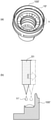
- FIG. 1 (a) is a perspective view showing a state in which a film raw material is supplied to a lens
- FIG. 1 (b) is an enlarged cross-sectional view of a region b surrounded by a broken line in FIG. 1 (a).
- 2 (a) and 2 (b) are process cross-sectional views schematically showing a conventionally known method for manufacturing a heat-generating film.
- FIG. 3 is a process sectional view schematically showing a method for producing a heat-generating film according to the first embodiment of the present disclosure.
- FIG. 4A is a perspective view schematically showing the heat-generating film according to the embodiment of the present disclosure
- FIG. 4B is a cross-sectional view schematically showing the heat-generating film according to the embodiment of the present disclosure.
- FIG. 5 is a cross-sectional view of an in-vehicle camera provided with a lens according to the embodiment of the present disclosure.
- FIG. 6 is a comparison diagram showing a contrast between a cross section of a film raw material containing a high boiling point solvent and a cross section of a film raw material containing a low boiling point solvent.
- FIG. 7 is a process perspective view schematically showing a method for manufacturing a heat-generating film according to the second embodiment of the present disclosure.
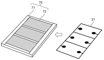
- FIG. 8 is a process perspective view schematically showing a method for manufacturing a heat-generating film according to the second embodiment of the present disclosure.
- FIG. 9 is a process perspective view schematically showing a method for manufacturing a heat-generating film according to the second embodiment of the present disclosure.
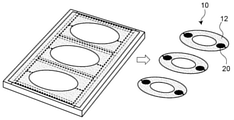
- FIG. 10 is a process perspective view schematically showing a method for producing a heat-generating film according to the second embodiment of the present disclosure.
- FIG. 11 is a process perspective view schematically showing a method for manufacturing a heat-generating film according to a modification 1 of the second embodiment of the present disclosure.
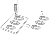
- FIG. 12 is a process perspective view schematically showing a method for manufacturing a heat-generating film according to Modification 2 of the second embodiment of the present disclosure.
- FIG. 13 is a process perspective view schematically showing a method for manufacturing a heat-generating film according to a modification 3 of the second embodiment of the present disclosure.
- FIG. 14 is a perspective view of a second embodiment of the heat-generating film of the present disclosure.
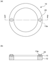
- FIG. 15 (a) is a plan view of the second embodiment of the heat-generating film of the present disclosure
- FIG. 15 (b) is a cross-sectional view taken along the line bb of FIG. 15 (a) in the direction of arrow.
- FIG. 16 is a perspective view of a third embodiment of the heat-generating film of the present disclosure.
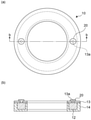
- 17 (a) is a plan view of the third embodiment of the heat-generating film of the present disclosure
- FIG. 17 (b) is a cross-sectional view taken along the line bb of FIG. 17 (a) in the direction of arrow.
- FIG. 18 is a cross-sectional view of a modified example of the third embodiment of the heat-generating film of the present disclosure.
- FIG. 18 is a cross-sectional view of a modified example of the third embodiment of the heat-generating film of the present disclosure.
- FIG. 19 is a plan view of a modified example of the third embodiment of the heat-generating film of the present disclosure.
- FIG. 20 is a plan view of a modified example of the third embodiment of the heat-generating film of the present disclosure.
- 21 (a) is a plan view of a fourth embodiment of the heat-generating film of the present disclosure, and FIG. 21 (b) is a cross-sectional view taken along the line bb of FIG. 21 (a) in the direction of arrow.
- 22 (a) is a plan view of a modified example of the fourth embodiment of the heat-generating film of the present disclosure, and FIG. 22 (b) is a cross-sectional view taken along the line bb of FIG. 22 (a) in the direction of arrow. ..
- FIG. 23 is a process perspective view schematically showing a manufacturing method for manufacturing the heat-generating films of the second embodiment and the third embodiment of the present disclosure.
- FIG. 24 is a process perspective view schematically showing a manufacturing method for manufacturing the heat-generating films of the second embodiment and the third embodiment of the present disclosure.
- FIG. 25 is a process perspective view schematically showing a manufacturing method for manufacturing the heat-generating films of the second embodiment and the third embodiment of the present disclosure.
- FIG. 26 is a process perspective view schematically showing a manufacturing method for manufacturing the heat-generating films of the second embodiment and the third embodiment of the present disclosure.
- FIG. 27 is a process perspective view schematically showing a manufacturing method for manufacturing the heat-generating film according to the fourth embodiment of the present disclosure.
- FIG. 24 is a process perspective view schematically showing a manufacturing method for manufacturing the heat-generating films of the second embodiment and the third embodiment of the present disclosure.
- FIG. 24 is a process perspective view schematically showing a manufacturing method for manufacturing the heat-generating films of the second embodiment and the
- FIG. 28 is a process perspective view schematically showing a manufacturing method for manufacturing the heat-generating film according to the fourth embodiment of the present disclosure.
- FIG. 29 is a process perspective view schematically showing a manufacturing method for manufacturing the heat-generating film according to the fourth embodiment of the present disclosure.
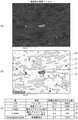
- 30 (a) is an SEM image of a heat-generating film of a comparative example
- FIG. 30 (b) is an elemental analysis mapping image
- FIG. 30 (c) is an elemental analysis table based on FIG. 30 (b).
- 31 (a) is an SEM image of the heat-generating film of the example
- FIG. 31 (b) is an elemental analysis mapping image
- FIG. 31 (c) is an elemental analysis table based on FIG. 31 (b).
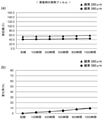
- FIG. 32 (a) is a graph showing the relationship between the resistance value and the elapsed time in an environment of a temperature of 85 ° C. and a humidity of 85% with respect to the heat-generating film of the comparative example
- FIG. 32 (b) is a graph showing the relationship between the heat-generating film and FIG. 32 (a).
- FIG. 33 (a) is a graph showing the relationship between the resistance value and the elapsed time in an environment of a temperature of 85 ° C. and a humidity of 85% with respect to the heat-generating film of the example
- FIG. 33 (b) is a graph showing the relationship of the elapsed time.
- a heater material in which a transparent conductive film such as ITO is formed as a thin film on a resin base material such as PET film, polyimide, or liquid crystal polymer, or carbon particles and a dielectric material on the resin base material.
- a resin base material such as PET film, polyimide, or liquid crystal polymer, or carbon particles and a dielectric material on the resin base material.
- a lens in which a film raw material containing carbon particles and a solvent is conventionally coated on a lens base material 100'and the film raw material is baked to provide a heat generating film 10' is known ( FIG. 1 (a)).
- a method of arranging the dispenser 51 above the lens base material 100'and applying the film raw material using the dispenser 51 can be mentioned (FIG. 1 (FIG. 1). b)).
- FIG. 2A shows a heat-generating film obtained by applying the film raw material 11'to the designed thickness using the dispenser 51, and then performing oven temporary baking (100 ° C.) for 10 minutes and main curing baking (200 ° C.) for 60 minutes.
- the cross section of is shown schematically. It is known that the volume of the heat-generating film raw material having a heater function shrinks to about 1/10 by baking, and in order to obtain a heat-generating film having a thickness of about 400 ⁇ m, a dispenser 51 has a thickness of about 4 mm. It was necessary to apply the film raw material 11'until. When the film raw material 11'is applied so as to be a thick film in this way, as shown in FIG. 2A, it is not possible to obtain a heat-generating film 10'with a desired shape, and the shape becomes unstable. Had.
- the manufacturing process schematically shown in FIG. 2B can be considered. That is, after applying one layer of the film raw material 11'with the dispenser 51, the oven temporary baking (100 ° C.) is performed for 10 minutes. Then, after applying one layer of the film raw material again, the oven temporary baking is performed again in the same manner. A manufacturing method is conceivable in which this is repeated until a heat-generating film precursor having a desired thickness is obtained, and then the main curing bake (200 ° C.) is performed for 60 minutes.
- the problem that the shape of the manufactured heat-generating film 10'is unstable can be solved, but the manufacturing process becomes complicated by repeating the coating of the film raw material and the oven temporary baking. Further, as will be described later, in the above manufacturing method, when the heat-generating film is subjected to a quality test in an environment of high temperature (85 ° C.) and high humidity (85%), the resistance value of the heat-generating film changes significantly after a long period of time, and the reliability is increased. It was a detriment to sex.
- FIG. 3 is a process sectional view schematically showing a method for producing a heat-generating film according to the first embodiment of the present disclosure.
- the film raw material 11 contains a carbon filler, a binder resin and a solvent.
- Carbon fillers are conductive and may be granular, flake or fibrous, carbon black, acetylene black, ketjen black, furnace black, natural graphite, artificial (artificial) graphite, kissed graphite, amorphous. At least one may be selected from the group consisting of carbon, hard carbon, soft carbon, activated carbon, carbon nanofibers, carbon nanotubes, and fullerene.
- conductivity in the present specification means that the surface electric resistance value is 107 ⁇ or less.
- the binder resin may contain a functional group that contributes to the curing reaction. Specifically, from the viewpoint of heat resistance or durability of the heat-generating film, it is preferable to contain a fluororesin, and more preferably, a fluororubber compound may be used.
- the binder resin contained in the film raw material may include the one in the state before the curing reaction.
- the solvent is preferably a low boiling point solvent having a boiling point of 150 ° C. or lower.
- the "boiling point" referred to in the present specification indicates the boiling point at 1 atm.
- the solvent is preferably a non-polar solvent.
- non-polar solvent means a solvent having a relative permittivity of 15 or less.
- toluene relative permittivity: 2.3
- xylene relative permittivity: 2.4
- butyl acetate relative permittivity: 5.0
- methylisobutylketone ratio
- At least one may be selected from the group consisting of a permittivity: 14.0), and if these solvents are contained, other solvents may be contained.
- the film raw material containing the carbon filler, the binder resin and the solvent preferably has a viscosity of 10,000 cps or more and 50,000 cps or less.
- viscosity refers to the viscosity at room temperature (20 ° C to 25 ° C).
- the film raw material has a certain degree of viscosity, so that unnecessary wetting and spreading is suppressed and the film shape has independent electrical characteristics and is stable without contacting peripheral members. Easy to handle.
- a BH type viscometer is used for measuring the viscosity, and as an example of the measurement conditions, a measured value of 25 ° C./1 minute and 50 rpm may be used.
- the method for producing a heat-generating film of the present disclosure includes a supply step of supplying a film raw material containing a carbon filler, a binder resin and a solvent.
- the film raw material 11 may be supplied to the lens base material 100. Specifically, it is preferable to supply the film raw material 11 so that the outer contour is circular and has a hole in the center (that is, a donut shape) in a plan view.
- the supply device 50 for supplying the film raw material may use a dispenser in order to supply the film raw material onto the lens base material with high accuracy, but the present invention is not limited to this example, and the spray coating device, the slit coater device, the die coater device, and the screen. At least one may be selected from the group consisting of a printing device, an inkjet device or a pad printing device. Further, a plurality of devices may be combined and supplied.
- the film raw material 11 When the film raw material 11 is supplied to the lens base material 100, the film raw material is supplied in a heated state or a normal temperature state of the lens base material 100 according to the supply thickness of the film raw material. Therefore, a heating element 60 for bringing the lens base material 100 into a heated state or a normal temperature state may be used.
- a thermal heater block may be used as the heating element 60, and the thermal heater block may have a structure that fits with the bottom surface of the lens base material 100.
- any heating method may be adopted as long as the film raw material can be heated.
- the heating element is provided with a method of heating by providing a coil heater in the heat heater block, a method of flowing a heat medium through the heat heater block to heat the heat, and a method of providing a microwave and high frequency heating device in the heater block. At least one may be selected from the group consisting of heating methods.
- the heating temperature in the heated state while suppressing the foaming generated on the surface of the coating film due to the volatilization of the solvent component is preferably about 30 to 80 ° C.
- the room temperature state indicates a room temperature (20 ° C to 25 ° C).
- the device for heating the heating element in contact with the lens base material has been described, but the present invention is not limited to this example, and for example, the heating element for heating without contacting the lens base material (
- the heating element for heating without contacting the lens base material may be a blower device such as a dryer).
- the supply thickness when the supply thickness is less than 120 ⁇ m, it is preferable to perform the supply step in a normal temperature state, and when the supply thickness is 120 ⁇ m or more, the supply step is performed in a heated state. It is preferable to do it.
- the supply thickness means the thickness of the coating film material after drying. This supply thickness will be described in detail with reference to FIG.
- the shape of the heat-generating film 10 to be manufactured differs depending on the flat area of the flat portion 111 (see FIG. 4B) on the back surface of the lens. That is, when the flat area of the flat portion of the lens is large in a plan view, the diameter of the hole in the center of the heat-generating film 10 manufactured as shown in FIG. 4A on the left is reduced to reduce the diameter of the heat-generating film 10. May be thinned. On the other hand, when the flat area of the flat portion of the lens is small in plan view, the diameter of the hole in the center of the heat-generating film 10 manufactured as shown in the right figure of FIG. 4A is increased to increase the diameter of the heat-generating film 10. May be thickened. As an example, FIG.
- FIG. 4A on the left illustrates a heat-generating film 10 having an outer contour diameter of 15.5 mm, a central hole diameter of 9 mm, and a film thickness of less than 120 ⁇ m
- FIG. 4A on the right shows an example.
- An example is a heat-generating film 10 having an outer contour diameter of 15.5 mm, a central hole diameter of 13.1 mm, and a film thickness of 120 ⁇ m or more.
- the film thickness may be set so that their volumes are substantially equal. In this case, the heat-generating film is used. It becomes easy to manage the resistance value per volume of the heater.
- a baking step of baking the film raw material may be carried out.
- the baking step may be performed by baking at a temperature of 180 ° C. to 220 ° C. for 60 minutes or more. This baking step causes a reaction in which the film raw material is cured to produce the heat-generating film 10. Before the baking step, a temporary baking step of temporarily curing the film raw material may be performed.
- a heat-generating film that heats the lens is manufactured.
- An electrode 20 (see FIG. 4B) for applying electric power to the heat-generating film 10 may be formed, and the electrode 20 is formed on the back surface of the heat-generating film 10 in order to facilitate wiring. It is preferable to form it on the surface opposite to the surface in contact with the lens).
- the heat-generating film 10 is arranged so as to be in direct contact with the lens 110, and the lens 110 can be heated by heating the heat-generating film 10. Further, the heat-generating film that generates heat of this lens may be used in a camera for exterior use, and may be provided in, for example, an in-vehicle camera (see FIG. 5).
- the heat-generating film manufactured through the manufacturing process of the present disclosure has a stable shape as compared with the heat-generating film manufactured by the manufacturing process schematically shown in FIG. 2 (a). Further, the heat-generating film can be manufactured by a simple process as compared with the manufacturing process schematically shown in FIG. 2 (b).
- the mode of supplying the film raw material to the lens base material 100 has been described, but the present invention is not limited to this example, and for example, the film raw material may be directly supplied to the lens 110.
- the heating element in that case may have a structure that fits with the lens 110.
- the heat-generating film manufactured through the manufacturing process of the present disclosure can directly form the heat-generating film with respect to the lens base material 100, the minimum number of parts can be obtained without using a base material or the like. Therefore, the cost can be reduced. Further, since the electrode 20 is installed on the back surface of the heat generating film 10 (the surface opposite to the surface in contact with the lens), the electrode and the lead member can be easily connected. If the flat area of the flat part of the lens is small and a load per area is applied, the thickness of the heat-generating film should be 120 ⁇ m or more, and if the flat area of the flat part of the lens is large and no load is applied per area, heat is generated. Since the thickness of the film is less than 120 ⁇ m, it is possible to produce a heat-generating film having good pressure resistance. It was
- FIG. 6 is a comparison diagram showing a contrast between a cross section of a film raw material containing a high boiling point solvent and a cross section of a film raw material containing a low boiling point solvent.
- FIG. 6 shows the film raw material 11'when a high boiling point solvent is used, the heat-generating film precursor 10a'after baking, and the heat-generating film 10 when measuring resistance in a high temperature (85 ° C.) and high humidity (85%) environment.
- the cross section of' is shown for each process.
- the solvent was difficult to volatilize, and when the cross section of the heat-generating film precursor 10a'after baking was seen, a loophole was formed in the volatile portion of the solvent.
- moisture or impurities caused by the surrounding high humidity environment were found in the loophole portion.
- the inventor of the present application has found that the resistance value of the heat-generating film 10'becomes unstable due to the intrusion.
- the lower part of FIG. 6 shows the film raw material 11 when a low boiling point solvent is used, the heat-generating film precursor 10a after baking, and the heat-generating film when measuring resistance in a high temperature (85 ° C.) and high humidity (85%) environment.
- the cross section of 10 is shown for each process.
- the solvent is easily volatilized, so that the loophole of the solvent is reduced when looking at the cross section of the heat generating film precursor 10a. Therefore, even if the heat-generating film 10 using this low boiling point solvent is tested in a high temperature (85 ° C.) and high humidity (85%) environment, the resistance value of the heat-generating film can be stabilized.
- FIGS. 7 to 10 are process cross-sectional views schematically showing a method for producing a heat-generating film according to the second embodiment of the present disclosure.
- the heat-generating film manufacturing method of the present embodiment may include a support member preparation step, a supply step of supplying a film raw material, a baking step, a peeling step, and a cutting step.
- the support member 70 may be used to support the film raw material (see FIG. 7).
- the support member 70 may include a frame 71 made of metal and a resin member 72 that is fitted to the frame 71 and has good peelability from a film raw material.
- the three resin members 72 may be fitted to the frame 71.
- the resin having good releasability from the film raw material at least one may be selected from the group consisting of a fluororesin, a Teflon resin (Teflon is a registered trademark), a silicone resin, and a polyethylene terephthalate resin film having a silicone resin arranged on the surface.
- the electrode frame 21 may be placed on the support member 70 (see FIG. 7).
- an electrode frame 21 having electrodes for producing three heat-generating films may be placed on the support member 70.
- the material of the electrode frame 21 may be a conductive material such as a copper plate or a copper foil, and may be a stainless foil, a copper material plated with gold, a stainless steel plated with gold, or the like.
- the thickness of the electrode frame 21 may be 5 to 50 ⁇ m or less. More preferably, it may be 30 ⁇ m or less.
- the corners of the contact surface between the frame 71 and the resin member 72 in the electrode frame 21 may be R-shaped, more preferably circular. This avoids stress concentration, prevents unexpected cracks on the film surface, and facilitates peeling.
- the film raw material may be supplied onto the support member 70 (see FIG. 8).
- a heating element 60 for bringing the support member 70 into a heated state or a normal temperature state may be used.
- the heating element 60 can be in contact with the support member 70 to heat the film raw material 11.
- at least one heating element 60 may be selected from the group consisting of a method using a coil heater, a method using a heat medium, and a method using microwaves and high frequency heating.
- the heating temperature in the heated state while suppressing the foaming generated on the surface of the coating film due to the volatilization of the solvent component is preferably about 30 to 80 ° C.
- the film raw material 11 may be supplied so as to cover at least the frame 71 and the resin member 72 by a coater device such as a die coater or a slit coater. Further, the film raw material 11 may be supplied so as to cover the frame 71, the resin member 72, and the electrode frame 21.
- the frame 71 enables simultaneous processing of a large number of products while preventing deformation such as warpage after the curing treatment of the coating film material, and can improve production efficiency.
- the supply thickness of the film raw material is less than 120 ⁇ m, it is preferable to carry out the supply step in a normal temperature state, and when the supply thickness is 120 ⁇ m or more, it is preferable to carry out the supply step in a heated state. Even when the supply thickness of the film raw material is less than 120 ⁇ m, the supply step may be performed in a heated state.
- the baking step may be carried out.
- the baking step may be performed by baking at a temperature of 180 ° C. to 220 ° C. for 60 minutes or more.
- the baking step causes a reaction in which the film raw material is cured, and the heat-generating film precursor 10a may be produced.
- a temporary baking step such as temporarily curing the film raw material may be performed.
- the three resin members 72 may be peeled off from the back surface of the support member 70 (see FIG. 9). By peeling off the three resin members 72, the heat-generating film precursor 10a obtained by the baking step may be exposed on the back surface of the support member 70.
- the structure of the support member 70 having the resin member 72 such that the three resin members 72 become one may be used.
- a cutting step of cutting the heat-generating film precursor 10a corresponding to the lens shape may be performed (see FIG. 10). Further, the resin member 72 may be peeled off after the cutting step is performed without peeling the resin member 72. Further, another material having the same shape as the resin member 72 may be inserted and cut. Further, when further cutting, the heat-generating film precursor 10a of FIG. 9 may be cut from the back side of the surface. In the cutting step, the heat-generating film precursor 10a is cut so that the outer contour is circular and has a hole in the center in a plan view, and the thicker the heat-generating film precursor, the larger the diameter of the heat-generating film. The precursor may be cleaved.
- the film thickness of the heat-generating film precursor when the film thickness of the heat-generating film precursor is less than 120 ⁇ m, the film is cut so that the diameter of the central hole becomes smaller, and the film thickness is reduced.
- the film thickness When is 120 ⁇ m or more, it may be cut so that the diameter of the central hole is large. That is, by cutting so that the volumes of both are substantially equal, it becomes easy to manage the resistance value per volume of the heater of the heat generating film.
- the heat-generating film can be manufactured through the above steps.
- This heat-generating film includes a heat-generating portion 12 that generates heat over the entire closed region. Then, by bringing the manufactured heat-generating film into contact with the lens, a lens provided with the heat-generating film can be manufactured. Further, the heat-generating film that generates heat of this lens may be used in a camera for exterior use, and may be provided in, for example, an in-vehicle camera.
- FIGS. 11 to 13 are process cross-sectional views schematically showing a method for manufacturing a heat-generating film according to Modifications 1 to 3 of the second embodiment of the present disclosure, respectively.
- the frame 71 made of metal and the support member 70 provided with the resin member 72 having good peelability from the film raw material have been described.
- the entire support member 70 may be used as a resin having good releasability from the film raw material (see FIG. 11).
- the peeling step can be completed in the form of a continuous coating film by peeling the support member 70 from the film raw material, so that the three resin members described in the second embodiment described above can be peeled off. It is efficient when manufacturing a product on a trial basis, for example, the product can be taken out with a smaller product pitch, and the manufacturing process is easy.
- the heat generating portion 12 is a conductive resistor in the entire closed region, the formation of the electrode 20 may be omitted.
- the film raw material is supplied by a coater device such as a die coater or a slit coater has been described, but instead of this configuration, the film raw material is supplied by using the dispenser 51. It may be (see FIG. 12). According to such a configuration, the film raw material can be accurately supplied by the dispenser 51. If the film raw material using the dispenser 51 is supplied, the cutting step for obtaining the heat-generating film 10 may be omitted.
- a screen printing device 52 may be used to supply the film raw material by moving the screen (see FIG. 13). According to such a configuration, a desired heat-generating film can be mass-produced by the screen printing method.
- the heat-generating film of the present disclosure -Structure of heat-generating film (first embodiment of heat-generating film)- Next, the heat-generating film manufactured by the above-described heat-generating film manufacturing method of the present disclosure will be described.
- the heat-generating film that heats the lens of the present disclosure comprises a carbon filler, a resin, and other inclusions, and the sum of the contents of the carbon filler and the resin is 90% or more.
- the "contents other than the carbon filler and the resin" referred to in the present specification indicate a content that is preferably present as a constituent component of the heat-generating film and an undesired content as a component of the heat-generating film.
- the “contents preferably present as constituents of the heat-generating film” refer to inclusions other than the carbon filler and the resin, which are caused by improving the characteristics of the heat-generating film.
- the “contents preferably present as constituents of the heat-generating film” refer to, for example, magnesium oxide particles, aluminum oxide, and silicon oxide particles.
- the “undesired inclusion” means a substance that is not substantially essential as a component of the heat-generating film in a broad sense, and exists as a component of a carbon filler, a resin and a heat-generating film in a narrow sense. Refers to substances other than the preferred inclusions.
- the "undesired content” refers to a composition other than carbon fibers, a binder resin, magnesium oxide particles, aluminum oxide and silicon oxide particles.
- the undesired inclusions may include, for example, barium sulfide particles, as well as moisture, pores and air.
- the heat-generating film may include a heat-generating portion that generates heat over the entire closed region.
- the entire closed region may be used as the heat generating portion.
- the "closed region” as used herein means, for example, a region surrounded by a straight line or a curved line and closed.
- the “whole area” is not limited to 100% of the closed region, and may be preferably 90% or more, more preferably 95% or more, and even more preferably 99% or more of the region.
- the film thickness of the heat-generating film is preferably 5 ⁇ m or more and 400 ⁇ m or less. By setting the film thickness in this range, the resistance value of the heat-generating film can be a desired design.
- the heat-generating film of the present disclosure is considered to be mainly used for applying electric power to the heat-generating film to melt the freezing matter adhering to the lens.
- the electric power applied to the heat-generating film needs to be such that the lens function is not impaired even if the lens is heated by the applied electric power. Further, it is required to melt a predetermined amount of freezing matter in a short time by using a heat-generating film.
- the resistance value of the heat-generating film was designed in consideration of these factors, and the resistance value of the heat-generating film of the present disclosure was set to about 20 to 60 ⁇ .
- the carbon filler may contain carbon fibers, and can reduce the fluctuation of the resistance value during operation as compared with the conventionally known carbon particles alone.
- the resin preferably contains a fluororesin.
- a fluororesin By containing a fluororesin, a heat-generating film having good heat resistance or durability can be obtained.
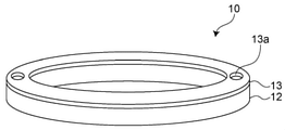
- the heat-generating film has a circular outer contour and a hole in the center in a plan view. With such a shape, a heat-generating film that matches the lens shape can be obtained.
- the heat generating portion 12 is in the form of a film, and as described above, the film thickness is preferably 5 ⁇ m or more and 400 ⁇ m or less.
- a base material 13 for holding the heat generating portion 12 may be provided.
- holding the heat-generating portion means a state in which the heat-generating portion is held in contact with the heat-generating portion, and the base material 13 is arranged below the heat-generating portion 12 to retain the heat-generating portion 12. This includes not only the state of being hung down, but also the state in which the heat generating portion 12 is maintained by arranging the base material 13 above or to the side of the heat generating portion 12.
- the base material 13 includes a state in which the heat generating portion 12 and the base material 13 are laminated so as to be in contact with each other.
- the rigidity of the heat generating film 10 can be increased.
- the heat-generating film is provided with the base material 13, it is possible to suppress the heat shrinkage of the film due to the high temperature of the heat-generating portion 12.
- the thickness of the base material 13 is preferably 5 ⁇ m or more and 100 ⁇ m or less.
- the base material 13 may have a circular outer contour and a hole in the center in a plan view corresponding to the heat generating portion 12.
- the shape of the base material 13 is not limited to this embodiment, and the contour or the shape of the hole may be elliptical or rectangular, and the contour and the shape of the hole may be different (for example, the contour may be rectangular).
- the shape of the hole may be an ellipse).
- the base material 13 preferably has heat resistance and insulating properties. Therefore, as the material used for the base material 13, for example, a heat-resistant insulating sheet such as polyimide, LCP, or polycarbonate may be used.
- heat resistance of the base material means having resistance to at least the heat generated by the heat generating portion
- insulation of the base material means having at least the heat generating portion having conductivity. It refers to the degree of insulation that can be electrically insulated.
- the base material 13 side may be brought into contact with the lens to generate heat (see FIGS. 15 (a) and 15 (b)).
- the lens can be easily heated by providing the wiring 22 on the heat generating portion 12 side. It also has the effect of retaining the heat of the heated lens by the base material 13 (heat insulating effect).
- the heat generating portion 12 side may be brought into contact with the lens. In this case, it can be realized by providing wiring for supplying electric power to the heat generating portion 12 inside the lens. Since the heat generating portion 12 comes into direct contact with the lens, the lens can be heated efficiently.
- the base material 13 may be provided with at least two through holes 13a for supplying electric power to the heat generating portion 12.
- the heat generating portion 12 is exposed when viewed in a plan view from the base material 13 side (see FIG. 16). It is possible to supply electric power to the heat generating portion 12 through the exposed portion of the heat generating portion 12.
- the electrode 20 When supplying electric power to the heat generating portion 12 through the through hole 13a, the electrode 20 may be embedded in the through hole 13a (see FIGS. 17 (a) and 17 (b)). Moreover, you may make an electrical connection using a conducting wire or the like without embedding the electrode 20. Further, from the viewpoint of manufacturing described later, a part of the heat generating portion 12 may be arranged in the through hole 13a (see FIG. 18).
- the through holes 13a may be arranged at symmetrical positions with the base material 13 as the center.
- the "target position” as used herein means a position where the through holes 13a overlap each other when rotated by 180 ° about the center of the base material 13 as a rotation axis. In this way, when the two through holes 13a are arranged at symmetrical positions with respect to the base material 13, the distances between the through holes 13a are substantially equal, so that the heat generating portion 12 can generate heat uniformly.
- the through holes 13a may be arranged at an asymmetrical position around the base material 13 (see FIG. 19).
- the "non-target position" as used herein means a position where the through holes 13a do not overlap each other even when rotated by 180 ° with the center of the base material 13 as the rotation axis.
- the distance between the through holes 13a will be different. For example, according to FIG. 19, in the distance between through holes along the heat generating portion 12, the distance between through holes along the upper heat generating portion 12 is L1 and the distance between through holes along the lower heat generating portion 12 is L2.
- the through-hole distance L1 is longer than the through-hole distance L2. That is, the current does not easily flow on the through-hole distance L1 side of the heat generating portion 12, and the current easily flows on the through-hole distance L2 side. Then, the heat generation portion 12 is less likely to generate heat on the L1 side of the through-hole distance, and is more likely to generate heat on the L2 side of the through-hole distance, so that the heat generation can be biased. According to such a configuration, for example, when the existence tendency of the freezing substance is known, for example, a large amount of the freezing substance is present on the L2 side of the through-hole distance, the heat generation is biased and the heat is effectively generated. be able to.
- the diameter of the through hole may be changed as the form of the through hole.
- the through hole diameter d1 on the right side may be used, and the through hole diameter d2 (> d1) on the left side may be used. Even in such a form, the heat-generating film can be effectively heated.
- the heat-generating film 10 may further include a covering portion 14 that covers the heat-generating portion 12.
- a covering portion 14 that covers the heat-generating portion 12.
- the covering portion 14 preferably has heat resistance and insulating properties. Therefore, as the material used for the covering portion 14, for example, a heat-resistant insulating resin such as polyimide, LCP, or polycarbonate may be used. Further, a photosensitive resin may be used for patterning to cover the heat generating portion 12.
- heat resistance of the covering portion means having resistance to at least the heat generated by the heat generating portion
- insulating property of the covering portion means having at least the heat generating portion having conductivity. It refers to the degree of insulation that can be electrically insulated.
- the heat generating portion 12 of the heat generating film 10 of the present embodiment is covered with the covering portion 14, it is possible to make it less susceptible to the influence of the external environment (for example, temperature or humidity).
- the term "covering the heat generating portion” as used herein is not limited to the fact that the entire outer surface of the heat generating portion 12 is covered, but also includes the case where a part of the heat generating portion 12 is covered. do. That is, as shown in FIGS. 22 (a) and 22 (b), a part of the heat generating portion 12 may be covered with the covering portion 14.
- the support member 70' may be a plate-shaped member having good peelability with respect to the base material 13.
- the base material 13 may be placed on the support member 70'(see FIG. 23).
- the base material 13 may have heat resistance and insulating properties, and for example, a heat resistant insulating sheet such as polyimide, LCP, or polycarbonate may be used.
- the base material 13 may be formed with a through hole 13a for supplying electric power to the alignment marker 13b and the heat generating film.
- the position of the through hole 13a may be the target position or the non-target position described above.
- the size of the through hole 13a may be the same or different.
- the film raw material may be supplied onto the base material 13 (see FIG. 24). At that time, a heating element 60 for bringing the support member 70'to a heated state or a normal temperature state may be used. According to the supply process, as described with reference to FIG. 18, a part of the heat generating portion 12 is arranged in the through hole 13a. The amount of the film raw material supplied may be controlled so that the heat generating portion 12 is not arranged in the through hole 13a.
- the baking step may be carried out.
- the baking step may be performed by baking at a temperature of 180 ° C. to 220 ° C. for 60 minutes or more.
- the baking step causes a reaction in which the film raw material is cured, and the heat-generating film precursor 10a may be produced.
- a temporary baking step such as temporarily curing the film raw material may be performed.
- the support member 70' is peeled from the base material 13 (see FIG. 25), and after finishing the peeling step, a cutting step of cutting the heat-generating film precursor 10a according to the lens shape is carried out. (See FIG. 26). Further, the electrode 20 may be embedded in the through hole 13a.
- the heat-generating film of the third embodiment shown in FIG. 16 can be manufactured.
- the heat-generating film of the second embodiment can be manufactured by using the base material 13 in which the through hole 13a is not formed.
- the patterned film raw material is supplied onto the base material 13 after the above-mentioned support member preparation step.
- the method for patterning the film raw material include a method using printing by a screen printing device or pad printing, and a method using drawing by a dispenser device, an inkjet device, a spray coating device, or the like.
- a heating element 60 for bringing the support member 70'to a heated state or a normal temperature state may be used.
- the baking step may be carried out.
- the baking step may be performed by baking at a temperature of 180 ° C. to 220 ° C. for 60 minutes or more.
- the baking step causes a reaction in which the film raw material is cured, and the heat-generating film precursor 10a may be produced.
- a temporary baking step such as temporarily curing the film raw material may be performed.
- a covering material 14'for forming the covering portion 14 may be supplied.
- the covering portion 14 preferably has heat resistance and insulating properties. Therefore, as the covering material 14'used for the covering portion 14, for example, a heat-resistant insulating resin such as polyimide, LCP, or polycarbonate may be used.
- the temporary curing at 100 ° C. or higher and 150 ° C. or lower may be performed for 1 hour or less, and the main curing at 200 ° C. or higher and 250 ° C. or lower may be performed for 2 hours or less.
- the support member 70' is peeled from the base material 13 (see FIG. 29), and after finishing the peeling step, a cutting step of cutting the heat-generating film precursor 10a according to the lens shape is performed. It may be carried out. Further, the electrode 20 may be embedded in the through hole 13a.
- the heat-generating film of the fourth embodiment shown in FIG. 21 or FIG. 22 can be manufactured.
- Example Heat-generating film manufactured by the manufacturing process schematically shown in FIG. 3
- Comparative example Heat-generating film manufactured by the manufacturing process schematically shown in FIG. 2 (b).
- Carbon filler Carbon black
- Binder resin Fluoro rubber compound and crystalline silica
- Solvent n-butyl acetate and methyl isobutyl ketone (hardener) Methanol, diethylenetriamine and silane compounds (diluting solvent) Methyl isobutyl ketone
- the contents of the verification test were observation of SEM images, elemental analysis, and aging measurement of the resistance value of the heat-generating film in a high-temperature and high-humidity environment for the heat-generating films of Examples and Comparative Examples.
- FIG. 30 (a) is an SEM image of the heat-generating film of the comparative example
- FIG. 31 (a) is an SEM image of the heat-generating film of the example.
- the SEM image is an image obtained by observing the surface of the heat-generating film at an acceleration voltage of 5 kV and 10000 times with a scanning electron microscope (JSM-7900F) manufactured by JEOL Ltd.
- FIG. 31 (b) is an elemental analysis mapping image of an example.
- the elemental analysis mapping image is an image obtained by Oxford Instruments' Ultratime Extreme at an acceleration voltage of 10 kV and 2000 times.
- the elemental analysis table of FIG. 30 (c) corresponds to FIG. 30 (b), and the area ratio of the portion A'(that is, the area ratio of the binder resin) is 63.2%, that of the portion B'.
- the area ratio (that is, the area ratio of the carbon filler) was 18.0%, and the sum of the partial A'and the partial B'was 81.2%.
- the portion A corresponds to the binder resin
- the portion B corresponds to the carbon filler
- the portion C corresponds to the magnesium oxide particles and the portion.
- D corresponds to aluminum oxide or silicon oxide particles
- partial E corresponds to an unassigned component.
- the elemental analysis table of FIG. 31 (c) corresponds to FIG. 31 (b), and the area ratio of the portion A (that is, the area ratio of the binder resin) is 74.9%, and the area ratio of the portion B is (That is, the area ratio of the carbon filler) was 21.1%, and the sum of the portions A and B was 96.0%.
- the sum of the carbon filler and the resin content is 90% or more based on the heat-generating film as a whole. Further, when the content of the carbon filler is 15% or more and 25% or less, it is preferable from the viewpoint of conductivity.
- the standard of the content rate shows the ratio when the whole heat-generating film is used as a reference.
- FIGS. 32 (a) and 33 (a) show.
- the vertical axis represents the resistance value ( ⁇ ) and the horizontal axis represents the elapsed time.
- graphs showing the rate of change of the resistance value corresponding to the graphs of FIGS. 32 (a) and 33 (a) are shown in FIGS. 32 (b) and 33 (b).
- the vertical axis indicates the rate of change (%) of the resistance value
- the horizontal axis indicates the elapsed time.
- the graphs shown by the circle points ( ⁇ ) are the graphs for the heat-generating film having a film thickness of 50 ⁇ m, and are indicated by the triangular points ( ⁇ ).
- the graph is a graph for a heat-generating film having a film thickness of 140 ⁇ m, and the graph shown by the square dots ( ⁇ ) corresponds to a graph for a heat-generating film having a film thickness of 350 ⁇ m.
- the resistance value was about 150 ⁇ in the initial state, and the change in the resistance value was small even after 1000 hours.
- the resistance value of about 84 ⁇ in the initial state increases to about 117 ⁇ after 1000 hours, and according to FIG. 32 (b). It was confirmed that the resistance value increased by 40% after 1000 hours.
- the resistance value of about 59 ⁇ in the initial state increased to about 96 ⁇ after 1000 hours, and according to FIG. 32 (b), it increased to about 96 ⁇ . It was confirmed that the resistance value increased by 64% after 1000 hours.
- the resistance value was larger than the design value (20 to 60 ⁇ ).
- the graphs of FIGS. 33 (a) and 33 (b) for the heat-generating film of the example the graphs shown by the triangular points ( ⁇ ) are the graphs for the heat-generating film having a film thickness of 260 ⁇ m, and are indicated by circle points ( ⁇ ).
- the graph is equivalent to a graph for a heat-generating film having a film thickness of 360 ⁇ m.
- the resistance value is about 53 ⁇ in the initial state, and the change in the resistance value is small at about 59 ⁇ even after 1000 hours have passed. It was confirmed. Further, according to the graph shown by the round dots (film thickness: 360 ⁇ m), it was confirmed that the resistance value was about 41.3 ⁇ in the initial state, and the change in the resistance value was small at about 45 ⁇ even after 1000 hours had passed. did. Then, according to the graphs shown by the triangular points and the round points in FIG. 33 (b), it was confirmed that the rate of change of the resistance value was about 10%. That is, the resistance value of the heat-generating film could be in the range of the design value (20 to 60 ⁇ ), and the change in the resistance value could be reduced even in a high-temperature and high-humidity environment.
- the heat-generating film produced by the manufacturing method of the present disclosure has excellent environmental resistance.
- the heat-generating film of the present disclosure can be used for a camera for a surveillance system such as disaster prevention and crime prevention, or a camera for exterior use such as an in-vehicle camera.
Landscapes
- Physics & Mathematics (AREA)
- General Physics & Mathematics (AREA)
- Optics & Photonics (AREA)
- Engineering & Computer Science (AREA)
- Aviation & Aerospace Engineering (AREA)
- Surface Heating Bodies (AREA)
- Lens Barrels (AREA)
- Camera Bodies And Camera Details Or Accessories (AREA)
- Cameras Adapted For Combination With Other Photographic Or Optical Apparatuses (AREA)
- Resistance Heating (AREA)
Priority Applications (3)
| Application Number | Priority Date | Filing Date | Title |
|---|---|---|---|
| US17/908,280 US20230128849A1 (en) | 2020-09-14 | 2021-09-03 | Manufacturing method for heating film, heating film, lens, and in-vehicle camera |
| JP2022547557A JP7345119B2 (ja) | 2020-09-14 | 2021-09-03 | 発熱フィルムの製造方法、発熱フィルム、レンズおよび車載カメラ |
| EP21866679.0A EP4213590A4 (en) | 2020-09-14 | 2021-09-03 | METHOD FOR MANUFACTURING A HEATING FILM, HEATING FILM, LENS AND ON-BOARD CAMERA |
Applications Claiming Priority (2)
| Application Number | Priority Date | Filing Date | Title |
|---|---|---|---|
| JP2020153993 | 2020-09-14 | ||
| JP2020-153993 | 2020-09-14 |
Publications (1)
| Publication Number | Publication Date |
|---|---|
| WO2022054720A1 true WO2022054720A1 (ja) | 2022-03-17 |
Family
ID=80631813
Family Applications (1)
| Application Number | Title | Priority Date | Filing Date |
|---|---|---|---|
| PCT/JP2021/032499 Ceased WO2022054720A1 (ja) | 2020-09-14 | 2021-09-03 | 発熱フィルムの製造方法、発熱フィルム、レンズおよび車載カメラ |
Country Status (4)
| Country | Link |
|---|---|
| US (1) | US20230128849A1 (https=) |
| EP (1) | EP4213590A4 (https=) |
| JP (1) | JP7345119B2 (https=) |
| WO (1) | WO2022054720A1 (https=) |
Families Citing this family (1)
| Publication number | Priority date | Publication date | Assignee | Title |
|---|---|---|---|---|
| USD1021032S1 (en) * | 2021-12-28 | 2024-04-02 | Shin-Etsu Polymer Co., Ltd. | Heat conducting unit |
Citations (9)
| Publication number | Priority date | Publication date | Assignee | Title |
|---|---|---|---|---|
| JPH08152795A (ja) * | 1994-11-30 | 1996-06-11 | Toshiba Lighting & Technol Corp | 定着ヒータ,定着装置および画像形成装置 |
| JP2001076850A (ja) * | 1999-09-02 | 2001-03-23 | Fujikura Ltd | 導電性インキ組成物およびそれを用いた面状発熱体 |
| JP2002117962A (ja) * | 2000-10-05 | 2002-04-19 | Hitachi Cable Ltd | 面状発熱体 |
| JP2005038788A (ja) * | 2003-07-18 | 2005-02-10 | T-Net Japan Co Ltd | 面状ヒータおよびその製造方法 |
| JP2007317618A (ja) * | 2006-05-29 | 2007-12-06 | Honda Sangyo Kk | 面状発熱体およびその製造方法 |
| JP2014096263A (ja) * | 2012-11-08 | 2014-05-22 | Hodogaya Chem Co Ltd | 面状ヒータ |
| WO2015076390A1 (ja) * | 2013-11-22 | 2015-05-28 | 東洋ドライルーブ株式会社 | 炭素発熱組成物及び炭素発熱体 |
| WO2019181122A1 (ja) | 2018-03-22 | 2019-09-26 | 日本電産コパル株式会社 | 撮像装置 |
| WO2019225745A1 (ja) | 2018-05-24 | 2019-11-28 | マクセル株式会社 | レンズユニットおよびカメラモジュール |
Family Cites Families (1)
| Publication number | Priority date | Publication date | Assignee | Title |
|---|---|---|---|---|
| KR102243382B1 (ko) * | 2018-11-30 | 2021-04-22 | 에이치엔티 일렉트로닉스(주) | 발열 기능이 구비된 카메라 모듈 및 그 제조방법 |
-
2021
- 2021-09-03 WO PCT/JP2021/032499 patent/WO2022054720A1/ja not_active Ceased
- 2021-09-03 JP JP2022547557A patent/JP7345119B2/ja active Active
- 2021-09-03 US US17/908,280 patent/US20230128849A1/en active Pending
- 2021-09-03 EP EP21866679.0A patent/EP4213590A4/en not_active Withdrawn
Patent Citations (9)
| Publication number | Priority date | Publication date | Assignee | Title |
|---|---|---|---|---|
| JPH08152795A (ja) * | 1994-11-30 | 1996-06-11 | Toshiba Lighting & Technol Corp | 定着ヒータ,定着装置および画像形成装置 |
| JP2001076850A (ja) * | 1999-09-02 | 2001-03-23 | Fujikura Ltd | 導電性インキ組成物およびそれを用いた面状発熱体 |
| JP2002117962A (ja) * | 2000-10-05 | 2002-04-19 | Hitachi Cable Ltd | 面状発熱体 |
| JP2005038788A (ja) * | 2003-07-18 | 2005-02-10 | T-Net Japan Co Ltd | 面状ヒータおよびその製造方法 |
| JP2007317618A (ja) * | 2006-05-29 | 2007-12-06 | Honda Sangyo Kk | 面状発熱体およびその製造方法 |
| JP2014096263A (ja) * | 2012-11-08 | 2014-05-22 | Hodogaya Chem Co Ltd | 面状ヒータ |
| WO2015076390A1 (ja) * | 2013-11-22 | 2015-05-28 | 東洋ドライルーブ株式会社 | 炭素発熱組成物及び炭素発熱体 |
| WO2019181122A1 (ja) | 2018-03-22 | 2019-09-26 | 日本電産コパル株式会社 | 撮像装置 |
| WO2019225745A1 (ja) | 2018-05-24 | 2019-11-28 | マクセル株式会社 | レンズユニットおよびカメラモジュール |
Non-Patent Citations (1)
| Title |
|---|
| See also references of EP4213590A4 |
Also Published As
| Publication number | Publication date |
|---|---|
| EP4213590A1 (en) | 2023-07-19 |
| JPWO2022054720A1 (https=) | 2022-03-17 |
| US20230128849A1 (en) | 2023-04-27 |
| EP4213590A4 (en) | 2024-06-26 |
| JP7345119B2 (ja) | 2023-09-15 |
Similar Documents
| Publication | Publication Date | Title |
|---|---|---|
| Liu et al. | Electrically robust silver nanowire patterns transferrable onto various substrates | |
| US10702887B2 (en) | Thin film forming apparatus and transparent conductive film | |
| CN105453001A (zh) | 将电子部件粘结到图案化纳米线透明导体 | |
| CN101983180A (zh) | 加热件及其制备方法 | |
| TWI828900B (zh) | 具有可制定電阻之厚膜電阻器及其製造方法 | |
| JP7345119B2 (ja) | 発熱フィルムの製造方法、発熱フィルム、レンズおよび車載カメラ | |
| JP6370111B2 (ja) | 容量型ガスセンサ及びその製造方法 | |
| TW444522B (en) | Process for forming polymer thick film resistors and metal thin film resistors in a printed circuited substrate | |
| TWI375341B (https=) | ||
| JP2011227999A (ja) | 面状発熱体 | |
| JP2012174374A (ja) | 導電性塗膜の製造方法及び導電性塗膜 | |
| JP2004531866A (ja) | 低温コンポーネントと一体化した厚膜ヒータおよびその製造方法 | |
| CN109300578B (zh) | 一种导电皮革材料及其制备方法 | |
| CN113764137A (zh) | 纳米银线导电膜的制备方法、纳米银线导电膜及其应用 | |
| WO2012096541A2 (ko) | 발열체 및 이의 제조방법 | |
| CN111566761B (zh) | 热敏电阻元件及其制造方法 | |
| JPH02153760A (ja) | 電荷移動像形成カートリッジおよびその製造方法 | |
| JP6016475B2 (ja) | 電子放出素子 | |
| CN114026191B (zh) | 异方性导电胶膜的制作方法 | |
| CN103563480A (zh) | 面状发热体及其制造方法 | |
| TW201139739A (en) | Method for preventing or reducing silver migration in the crossover areas of a membrane touch switch | |
| CN118401625A (zh) | 电路连接用黏合剂带、连接结构体及连接结构体的制造方法 | |
| JP2007110054A (ja) | パターン形成方法およびパターン形成ずみ基板 | |
| CN114051523B (zh) | 导电粒子隔开距离得到控制的异方性导电胶膜的制备方法 | |
| KR101584916B1 (ko) | 질화알미늄이 코팅된 고분자 볼을 첨가한 솔더 레지스터의 제조방법 |
Legal Events
| Date | Code | Title | Description |
|---|---|---|---|
| 121 | Ep: the epo has been informed by wipo that ep was designated in this application |
Ref document number: 21866679 Country of ref document: EP Kind code of ref document: A1 |
|
| ENP | Entry into the national phase |
Ref document number: 2022547557 Country of ref document: JP Kind code of ref document: A |
|
| WWE | Wipo information: entry into national phase |
Ref document number: 2021866679 Country of ref document: EP |
|
| NENP | Non-entry into the national phase |
Ref country code: DE |
|
| ENP | Entry into the national phase |
Ref document number: 2021866679 Country of ref document: EP Effective date: 20230414 |
|
| WWW | Wipo information: withdrawn in national office |
Ref document number: 2021866679 Country of ref document: EP |