WO2022050371A1 - 薬剤撮影装置および薬剤分包装置 - Google Patents
薬剤撮影装置および薬剤分包装置 Download PDFInfo
- Publication number
- WO2022050371A1 WO2022050371A1 PCT/JP2021/032393 JP2021032393W WO2022050371A1 WO 2022050371 A1 WO2022050371 A1 WO 2022050371A1 JP 2021032393 W JP2021032393 W JP 2021032393W WO 2022050371 A1 WO2022050371 A1 WO 2022050371A1
- Authority
- WO
- WIPO (PCT)
- Prior art keywords
- drug
- unit
- imaging
- drugs
- packaging
- Prior art date
- Legal status (The legal status is an assumption and is not a legal conclusion. Google has not performed a legal analysis and makes no representation as to the accuracy of the status listed.)
- Ceased
Links
Images







Classifications
-
- A—HUMAN NECESSITIES
- A61—MEDICAL OR VETERINARY SCIENCE; HYGIENE
- A61J—CONTAINERS SPECIALLY ADAPTED FOR MEDICAL OR PHARMACEUTICAL PURPOSES; DEVICES OR METHODS SPECIALLY ADAPTED FOR BRINGING PHARMACEUTICAL PRODUCTS INTO PARTICULAR PHYSICAL OR ADMINISTERING FORMS; DEVICES FOR ADMINISTERING FOOD OR MEDICINES ORALLY; BABY COMFORTERS; DEVICES FOR RECEIVING SPITTLE
- A61J3/00—Devices or methods specially adapted for bringing pharmaceutical products into particular physical or administering forms
- A61J3/07—Devices or methods specially adapted for bringing pharmaceutical products into particular physical or administering forms into the form of capsules or similar small containers for oral use
- A61J3/071—Devices or methods specially adapted for bringing pharmaceutical products into particular physical or administering forms into the form of capsules or similar small containers for oral use into the form of telescopically engaged two-piece capsules
- A61J3/074—Filling capsules; Related operations
-
- B—PERFORMING OPERATIONS; TRANSPORTING
- B65—CONVEYING; PACKING; STORING; HANDLING THIN OR FILAMENTARY MATERIAL
- B65B—MACHINES, APPARATUS OR DEVICES FOR, OR METHODS OF, PACKAGING ARTICLES OR MATERIALS; UNPACKING
- B65B57/00—Automatic control, checking, warning, or safety devices
- B65B57/10—Automatic control, checking, warning, or safety devices responsive to absence, presence, abnormal feed, or misplacement of articles or materials to be packaged
- B65B57/14—Automatic control, checking, warning, or safety devices responsive to absence, presence, abnormal feed, or misplacement of articles or materials to be packaged and operating to control, or stop, the feed of articles or material to be packaged
-
- B—PERFORMING OPERATIONS; TRANSPORTING
- B65—CONVEYING; PACKING; STORING; HANDLING THIN OR FILAMENTARY MATERIAL
- B65B—MACHINES, APPARATUS OR DEVICES FOR, OR METHODS OF, PACKAGING ARTICLES OR MATERIALS; UNPACKING
- B65B1/00—Packaging fluent solid material, e.g. powders, granular or loose fibrous material, loose masses of small articles, in individual containers or receptacles, e.g. bags, sacks, boxes, cartons, cans, or jars
- B65B1/30—Devices or methods for controlling or determining the quantity or quality or the material fed or filled
-
- B—PERFORMING OPERATIONS; TRANSPORTING
- B65—CONVEYING; PACKING; STORING; HANDLING THIN OR FILAMENTARY MATERIAL
- B65B—MACHINES, APPARATUS OR DEVICES FOR, OR METHODS OF, PACKAGING ARTICLES OR MATERIALS; UNPACKING
- B65B35/00—Supplying, feeding, arranging or orientating articles to be packaged
- B65B35/06—Separating single articles from loose masses of articles
- B65B35/08—Separating single articles from loose masses of articles using pocketed conveyors
-
- B—PERFORMING OPERATIONS; TRANSPORTING
- B65—CONVEYING; PACKING; STORING; HANDLING THIN OR FILAMENTARY MATERIAL
- B65B—MACHINES, APPARATUS OR DEVICES FOR, OR METHODS OF, PACKAGING ARTICLES OR MATERIALS; UNPACKING
- B65B5/00—Packaging individual articles in containers or receptacles, e.g. bags, sacks, boxes, cartons, cans, jars
- B65B5/10—Filling containers or receptacles progressively or in stages by introducing successive articles, or layers of articles
- B65B5/101—Filling containers or receptacles progressively or in stages by introducing successive articles, or layers of articles by gravity
- B65B5/103—Filling containers or receptacles progressively or in stages by introducing successive articles, or layers of articles by gravity for packaging pills or tablets
-
- B—PERFORMING OPERATIONS; TRANSPORTING
- B65—CONVEYING; PACKING; STORING; HANDLING THIN OR FILAMENTARY MATERIAL
- B65B—MACHINES, APPARATUS OR DEVICES FOR, OR METHODS OF, PACKAGING ARTICLES OR MATERIALS; UNPACKING
- B65B57/00—Automatic control, checking, warning, or safety devices
- B65B57/20—Applications of counting devices for controlling the feed of articles
-
- B—PERFORMING OPERATIONS; TRANSPORTING
- B65—CONVEYING; PACKING; STORING; HANDLING THIN OR FILAMENTARY MATERIAL
- B65B—MACHINES, APPARATUS OR DEVICES FOR, OR METHODS OF, PACKAGING ARTICLES OR MATERIALS; UNPACKING
- B65B59/00—Arrangements to enable machines to handle articles of different sizes, to produce packages of different sizes, to vary the contents of packages, to handle different types of packaging material, or to give access for cleaning or maintenance purposes
- B65B59/001—Arrangements to enable adjustments related to the product to be packaged
-
- G—PHYSICS
- G01—MEASURING; TESTING
- G01N—INVESTIGATING OR ANALYSING MATERIALS BY DETERMINING THEIR CHEMICAL OR PHYSICAL PROPERTIES
- G01N21/00—Investigating or analysing materials by the use of optical means, i.e. using sub-millimetre waves, infrared, visible or ultraviolet light
- G01N21/84—Systems specially adapted for particular applications
- G01N21/85—Investigating moving fluids or granular solids
-
- G—PHYSICS
- G01—MEASURING; TESTING
- G01N—INVESTIGATING OR ANALYSING MATERIALS BY DETERMINING THEIR CHEMICAL OR PHYSICAL PROPERTIES
- G01N21/00—Investigating or analysing materials by the use of optical means, i.e. using sub-millimetre waves, infrared, visible or ultraviolet light
- G01N21/84—Systems specially adapted for particular applications
- G01N21/88—Investigating the presence of flaws or contamination
- G01N21/95—Investigating the presence of flaws or contamination characterised by the material or shape of the object to be examined
- G01N21/9508—Capsules; Tablets
-
- G—PHYSICS
- G06—COMPUTING OR CALCULATING; COUNTING
- G06T—IMAGE DATA PROCESSING OR GENERATION, IN GENERAL
- G06T7/00—Image analysis
- G06T7/0002—Inspection of images, e.g. flaw detection
- G06T7/0012—Biomedical image inspection
-
- B—PERFORMING OPERATIONS; TRANSPORTING
- B65—CONVEYING; PACKING; STORING; HANDLING THIN OR FILAMENTARY MATERIAL
- B65B—MACHINES, APPARATUS OR DEVICES FOR, OR METHODS OF, PACKAGING ARTICLES OR MATERIALS; UNPACKING
- B65B1/00—Packaging fluent solid material, e.g. powders, granular or loose fibrous material, loose masses of small articles, in individual containers or receptacles, e.g. bags, sacks, boxes, cartons, cans, or jars
- B65B1/04—Methods of, or means for, filling the material into the containers or receptacles
- B65B1/06—Methods of, or means for, filling the material into the containers or receptacles by gravity flow
-
- B—PERFORMING OPERATIONS; TRANSPORTING
- B65—CONVEYING; PACKING; STORING; HANDLING THIN OR FILAMENTARY MATERIAL
- B65B—MACHINES, APPARATUS OR DEVICES FOR, OR METHODS OF, PACKAGING ARTICLES OR MATERIALS; UNPACKING
- B65B2220/00—Specific aspects of the packaging operation
- B65B2220/14—Adding more than one type of material or article to the same package
-
- G—PHYSICS
- G06—COMPUTING OR CALCULATING; COUNTING
- G06T—IMAGE DATA PROCESSING OR GENERATION, IN GENERAL
- G06T2207/00—Indexing scheme for image analysis or image enhancement
- G06T2207/30—Subject of image; Context of image processing
- G06T2207/30242—Counting objects in image
Definitions
- the present invention relates to a drug imaging device for photographing a drug such as a tablet or a capsule before packaging, and a drug packaging device for packaging the photographed drug.
- Patent Document 1 describes a drug supply unit that supplies various drugs, a drug packaging unit that packages the drugs supplied from the drug supply unit with a packing paper, and a component in the drug packaging unit that packages the drugs.
- a drug packaging device including an introduction member to be introduced into a packing paper and a drug check unit for determining whether or not the drug is attached to the introduction member based on an image of the introduction member is disclosed. Has been done.
- the drug check section is a drug identification section in which a drug is rotated by a drug turning section in which a pair of rotating rollers are arranged to photograph and determine the marking and printing of the drug, and a package on the upstream side of the introduction member. It is provided with a number determination unit for determining the number of drugs by photographing the drugs to be divided.
- Patent Document 2 discloses a drug information acquisition device.
- the bottom of the image pickup tray that temporarily holds one package of drug is composed of a row of V-shaped grooves, and the image pickup tray after the drug is charged is vibrated to serve one package.
- the overlap of the medicines is eliminated, and the posture of the medicines is corrected by the first inclined surface and the second inclined surface of the V-shaped groove.
- the two cameras are arranged so as to face the first inclined surface and the second inclined surface of the V-shaped groove, respectively.
- the imaging location for photographing the marking of the drug and the imaging location for determining the number of agents are different, so that the structure becomes complicated and the drug imaging process takes time. There was a drawback. Further, in the above-mentioned conventional device, since the outer shape information of the medicine is acquired by processing the image of the medicine taken in a non-backlit state, it is difficult to accurately specify the outer shape information of the medicine having the same color as the background color. rice field.
- the present invention is a drug imaging device and a drug capable of speeding up the drug imaging process and improving the accuracy of determining the number of drugs by both imaging the marking of the drug and the like and imaging the determination of the number of drugs in the drug storage section.
- a packaging device is provided.
- the drug imaging device of the present invention is a drug imaging device including an imaging section for still photographing a drug, and the imaging section captures a drug in a storage section for temporarily storing the drug before packaging in a non-backlit state. It is characterized by performing an imaging process of photographing the drug in the storage portion in a backlit state.
- the imaging unit has a first imaging process in which the drug in the reservoir is photographed from one side in a non-backlit state, a second imaging process in which the drug in the reservoir is photographed in a non-backlit state, and the drug in the reservoir is non-backlit from the other side.
- the third shooting process of shooting in the state may be performed.
- the first imaging process it is possible to photograph the marking or the like of the drug located so that the surface with the marking or the like faces upward, for example, and by the third photographing process, the marking or the like can be photographed. It is possible to take a picture of the stamp, etc. of the drug located with the side with the stamp, etc. facing down. This makes it possible to identify the drug in the reservoir based on the images obtained in the first and third imaging processes even for the drug with a stamp or the like on only one side. In addition, it becomes easy to count the number of drugs in the reservoir by the shadow image of the drug obtained by the second imaging process.
- the photographing unit includes a first camera that photographs the drug in the reservoir from above, an upper lighting unit that illuminates the drug in the reservoir from above, and a second camera that photographs the drug in the reservoir from below.
- a lower lighting unit that illuminates the drug in the storage unit from below may be provided.
- the photographing unit is provided with a surface emitting member capable of switching between a surface emitting state and a transparent state on the lower side of the bottom surface of the storage unit, and the first photographing process is performed depending on the transparent state of the surface emitting member.
- the third imaging process may be executed, and the second imaging process may be executed depending on the surface emission state of the surface emitting member.
- the photographing unit is provided with a dimming member capable of switching between a transparent state and a translucent state on the lower side of the bottom surface of the storage unit, and the first photographing process and the first imaging process are performed depending on the transparent state of the dimming member.
- the imaging process may be executed, and the second imaging process may be executed depending on the translucent state of the dimming member and the lighting of the lower illumination unit.
- the shooting unit may execute each shooting process a plurality of times within a fixed time for the same subject.
- the time required for taking the picture of the drug becomes long.
- a plurality of images are obtained, so that an image in which the engraved surface or the printed surface of the drug faces toward the camera is stochastically obtained. It becomes easy to be printed, and the recognition rate of the stamp or the like can be increased.
- the drug packaging device of the present invention is supplied from a drug supply unit that supplies various drugs, a drug packaging unit that packages the drugs supplied from the drug supply unit with a packing paper, and a drug supply unit. Even if the drug imaging device having a plurality of storage sections for temporarily storing the drug to be stored on the upstream side of the drug packaging section and an image output section for outputting an image captured by the drug imaging device are provided. good.
- the inspector can visually recognize the drug in the reservoir from the image taken by the drug imaging device, so that the drug can be appropriately checked in the drug packaging.
- the drug packaging device of the present invention is supplied from a drug supply unit that supplies various drugs, a drug packaging unit that packages the drugs supplied from the drug supply unit with a packing paper, and a drug supply unit.
- the number of drugs and drug information in the storage section are determined based on the drug imaging device having a plurality of storage sections for temporarily storing the drug to be stored on the upstream side of the drug packaging section and the images taken by the drug imaging device. It may be provided with a judgment unit.
- the drug packaging device may further include a third camera that photographs the inside of the storage section at a position where the drug stored in the storage section is passed to the drug packaging section. According to this, it becomes possible to detect the drug adhering to the reservoir by taking a picture with the third camera, and when such a drug is found, the user is informed that the packaged drug may not be as prescribed. be able to.
- a rotary disk unit that is rotationally driven around a shaft, has a plurality of openings on the same circumference around the shaft, and supplies drugs to the openings from the drug supply unit. And a drug receiving bottom having a portion that functions as the bottom of the opening, and a packaging opening provided at a specific location in a region where the opening moves by rotation of the turntable.
- a plate portion is provided, and the plurality of storage portions are composed of the opening portion and the portion functioning as the bottom portion of the opening portion, and the portion not forming the opening portion on the bottom surface side of the rotary plate portion.
- the cleaning member that cleans the top of the medicine receiving bottom portion by the rotation of the turntable portion may be provided.
- the cleaning member since the drug powder on the drug receiving bottom is removed by the cleaning member, it is possible to save the user the trouble of cleaning the drug receiving bottom. Then, by cleaning with the cleaning member, the problem of inappropriate lighting caused by the drug powder in the storage portion, the problem of misidentifying a lump of the drug powder as one drug, and the like are solved.
- the present invention it is possible to speed up the drug imaging process and improve the accuracy of determining the number of drugs by performing both the imaging of the marking of the drug and the imaging of the determination of the number of drugs in the storage section of the drug. It works.
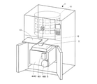
- FIG. 1A is an explanatory diagram showing a schematic configuration of the drug packaging device of FIG. 1
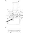
- FIG. 6B is an explanatory diagram showing a configuration example in which a dimming member is used instead of the surface light emitting member. ..
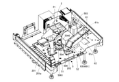
- FIG. 4 is a perspective view showing the first camera and the like omitted.
- FIG. 5 is a perspective view showing the residual detection camera and the like omitted in FIG. FIG.
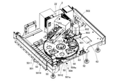
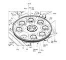
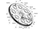
- FIG. 6 is a perspective view showing the upper plate of the drug receiving board portion omitted. It is a perspective view which showed the medicine receiving board part of FIG. 7 in an enlarged manner.
- FIG. (A) is a plan view of a drug receiving board portion in which the upper plate is omitted
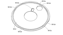
- FIG. 6 (B) is a cross-sectional view taken along the line AA in a state where the upper plate is arranged. It is a perspective view which showed the drug receiving bottom part located under the drug receiving board part. It is a perspective view which showed the bottom surface side of the drug receiving board part.
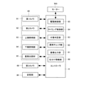
- FIG. 6 is a perspective view showing the drug receiving board portion omitted. It is a schematic block diagram which showed a part of the control system of the medicine packaging apparatus of FIG.
- the drug packaging device 1 of this embodiment can accommodate each type of drug and dispense the drug one by one by the packaging data created based on the prescription information.
- the drug storage / delivery unit 11 which is a drug supply unit
- the drug guide unit 12 which receives the drug
- the drug storage unit 5 which temporarily stores the drug
- the drug supplied to the drug storage unit 5 are still photographed.
- the drug photographing apparatus 6 of this embodiment, the packing paper roll 400 and the ink ribbon cassette 401 are attached, and printing is performed on the packing paper S supplied from the packing paper roll 400, and the packing paper S is printed. It is provided with a packaging unit 4 for packaging the drug that has passed through the drug storage unit 5 for each packet.
- the drug storage and dispensing unit 11 includes a cassette for drugs in which various drugs are stored and a universal cassette that can store drugs that are unsuitable for storage in the cassette.
- the above-mentioned drug cassette is a dedicated cassette prepared for each drug in which the size of the drug delivery route corresponds to the shape and size of each drug, and the above universal cassette is as needed.
- It is a general-purpose cassette that can dispense drugs of various shapes and sizes by making it possible to adjust the size and driving conditions of the drug dispensing route.
- the prescription information includes, for example, the usual drug type and number. However, information on the mark of the drug (information on the presence or absence of the mark, information on the appearance shape of the mark, etc.), size, shape, and color can be obtained by referring to the drug master table described later based on the drug type.
- the drug packaging device 1 is provided with a hand-spraying portion 13.
- the hand-spraying portion 13 has boxes arranged in a grid pattern so that a drug can be put into each box. For example, if morning, noon, and evening are prescribed for one day, the medicine will be put in three boxes.
- the drug dispensed from the drug accommodating and dispensing unit 11 and the drug hand-spread by the hand-spraying unit 13 reach the drug storage unit 5 via the drug guide unit 12 and the like.
- the drug residing in the drug storage unit 5 is still photographed by the drug imaging device 6, and then packaged in the packaging unit 4 with a packing paper. That is, in this embodiment, one packet of the drug is discharged by the joint operation of the drug accommodating and dispensing unit 11 and the hand-spreading unit 13.
- the route of the drug discharged from the drug accommodating and paying unit 11 and the hand-spraying unit 13 to the drug storage unit 5 will be described later with reference to FIG. 4 and the like.
- FIG. 2 is a diagram showing an example of the packaging unit 4 in a state where the packing paper roll 400 and the ink ribbon cassette 401 are mounted.
- FIG. 2 also shows the drug packaging unit 45 of the packaging unit 4.
- the drug packaging unit 45 introduces the drug from, for example, the opening of the packaged paper S folded in half, and heat-welds the packaged paper S so as to seal the introduced drug.
- FIG. 3 (A) shows the overall schematic configuration of the drug packaging device 1.
- the drug storage unit 5 and the drug imaging device 6 are located between the drug storage / delivery unit 11 and the packaging unit 4.
- the drug storage unit 5 has an upper plate portion 51 and a lower plate portion 52. Further, the drug storage unit 5 has a drug receiving board 501 in a space between the upper plate 51 and the lower plate 52.
- the drug receiving board portion 501 is located on the disc-shaped rotary disk section 5010, the upper plate 5011 fixed to the upper surface side of the rotary disk section 5010, and the lower surface side of the rotary disk section 5010.
- a drug transfer section 2, a first camera 61, and the like are attached to the upper surface portion of the upper plate portion 51.
- the dip slope 5010 and the upper plate 5011 in the drug receiving board 501 can rotate in a horizontal plane about the shaft 504 on the upper surface side (inside the space) of the lower plate 52. be.
- the medicine receiving bottom portion 5012 is attached so as not to rotate on the lower plate portion 52, and is attached so as to be removable from the lower plate portion 52.
- a convex portion protruding upward is provided on the lower plate portion 52, and the convex portion cannot be rotated by engaging with the concave portion 5012d (see FIG. 10) on the outer periphery of the drug receiving bottom portion 5012.
- a motor 503 or the like is attached to the upper surface of the lower plate portion 52.
- a drug packaging introduction member 7, a second camera 62, and the like are attached to the lower surface side of the lower plate portion 52.
- the drug receiving board 501 including the dip slope 5010 and the drug receiving bottom 5012 has, for example, eight storage sections 50. Each storage unit 50 temporarily stores the drug before it is packaged. The eight storage portions 50 are located at regular intervals on the same circumference centered on the shaft 504. The drug supplied to each reservoir 50 is supported by the drug receiving bottom 5012. The turntable portion 5010 can be detached from the drug receiving bottom portion 5012.
- each storage portion 50 has a tubular portion (opening) 50a made of a transparent material (resin or the like) that transmits light, and the above-mentioned drug receiving bottom portion that functions as the bottom of the tubular portion 50a. It is composed of a site of 5012, and the drug is stored inside the tubular portion 50a.
- the medicine receiving bottom portion 5012 is arranged horizontally, and the direction orthogonal to this is the vertical direction.
- the image pickup optical axis of the cameras 61, 62, 66 which will be described later, is in the vertical direction toward the portion of the drug receiving bottom portion 5012 that functions as the bottom portion of the tubular portion (opening portion) 50a.
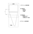
- an inclined mirror portion 6a forming a frustum-shaped mirror surface is arranged so as to be separated from the outer peripheral surface of the tubular portion 50a toward the upper side.
- the tubular portion 50a is located in the center of the tilted mirror portion 6a.
- the lower end of the tilted mirror portion 6a is in contact with the outer peripheral portion of the lower end of the tubular portion 50a.
- the upper end surface of the tubular portion 50a is processed into a frosted glass surface (micro uneven surface) or a light-impermeable surface.
- a square opening matching the plan view shape of the tubular portion 50a is formed at a position where the tubular portion 50a is located, and the drug is introduced into the tubular portion 50a through the square opening. Can be reached.
- the upper plate 5011 is entirely transparent, or at least a portion located above the tilted mirror portion 6a is transparent.
- connection points R1 of the adjacent surfaces on the six surfaces of the tubular portion 50a of the storage portion 50 are formed in a curved surface shape (R: R).
- R curved surface shape
- the lower end of the inner shape of the tubular portion 50a forms, for example, a hexagonal opening in a plan view.
- the drug receiving bottom 5012 is made of a transparent material (resin or the like) that transmits light. Further, as shown in FIG. 10, a packaging opening 5012a is formed at a predetermined position of the drug receiving bottom portion 5012.
- the drug packaging introduction member 7 When the drug packaging introduction member 7 is located below the packaging opening 5012a and the tubular portion 50a of the storage section 50 is located above the packaging opening 5012a, the drug in the storage section 50 is the drug. It falls into the packaging introduction member 7 and reaches the inside of the packing paper S. That is, the packaging opening 5012a is located at a specific position in a region where the cylinder portion (opening portion) 50a is moved by the rotation of the turntable portion 5010. Similarly, the lower plate portion 52 is also formed with an opening at a position corresponding to the packaging opening 5012a.
- each storage section 50 has a first drug receiving position P1 and a second drug as shown in FIGS. 6 and 7.
- a plurality of wheels 56 are attached to the lower surface of the turntable portion 5010, and while the load of the turntable portion 5010 is received by the drug receiving bottom portion 5012, the wheels rotate with the upper surface of the drug receiving bottom portion 5012.
- the drug transferred by the drug transfer unit 2 falls into the storage unit 50 located at the position P1.
- the drug transfer unit 2 has a hopper 21 located below the drug guide unit 12 and above the residual drug confirmation position P8. Further, the drug transfer unit 2 has a belt-driven transfer unit 22.
- the transfer unit 22 is located between the lower part of the hopper 21 and the first drug receiving position P1, and the drug received from the hopper 21 is placed in the storage unit 50 of the first drug receiving position P1. Transfer.
- Drugs are supplied from another drug supply unit to the second drug receiving position P2.
- the drug supplied from the universal cassette (not shown) is supplied into the storage unit 50 located at the position P3 via the guide cylinder 201 and the supply opening 201a.
- the universal cassette can supply the drug regardless of the shape of the drug, and automatically executes the drug discharge instead of the hand-spraying process of the drug.
- the drug accommodating and dispensing unit 11 includes a plurality of cassettes, some of which are universal cassettes.
- the drug supplied from the hand-spraying section 13 is supplied into the storage section 50 located at the position P5 via a hopper and a supply opening 202 (not shown).
- the drug (for example, a plurality of drugs for one packet) is temporarily stored in the storage section 50 located at the position P6.
- the drug imaging device 6 is located in the vicinity of the drug imaging position P6.
- the drug photographing device 6 has an photographing unit 60 for still photographing a subject.
- the imaging unit 60 has a first camera 61 that color-photographs the drug in the storage unit 50 located at the drug imaging position P6 from above and a color image of the drug in the storage unit 50 from below.
- the second camera 62 for taking a picture, the upper lighting unit 63 that illuminates the drug in the storage unit 50 from above, and the tilt mirror unit 6a (light emitting element that replaces the tilt mirror unit 6a) that illuminates the drug in the storage unit 50 from the side. It may be.),
- a lower lighting unit 64 that illuminates the medicine in the storage unit 50 from the lower side.
- the peripheral portion of the light inlet of the first camera 61 is in contact with the outer surface of the housing 6001 of the upper lighting unit 63. Further, a seal member (O-ring or the like) is arranged at the contact point. This sealing member prevents dust and the like from entering the housing 6001 from the first camera 61 side.
- the photographing unit 60 of the drug photographing apparatus 6 is provided with a surface light emitting member 65 on the lower side of the lower lighting unit 64.
- the portion of the lower plate portion 52 corresponding to the drug imaging position P6 is transparent or open.
- the surface light emitting member 65 has, for example, a rectangular shape, and can switch between a surface light emitting state and a transparent state. In the surface light emitting state, for the first camera 61, the photographing of the above-mentioned chemical is backlit.
- the surface light emitting member 65 includes, for example, a rectangular transparent light guide plate and a light emitting element (LED or the like) that emits light toward the edge of the transparent light guide plate.
- the surface light emitting member 65 is in a transparent state when the light emitting element is not lit.
- the surface light emitting member 65 may be located above the lower illumination unit 64.
- the photographing unit 60 lights the upper lighting unit 63 under the control of the controller 8 shown in FIG. 13, and uses the first camera 61 to display the drug in the storage unit 50 from above in a non-backlit state.
- the first imaging process of photographing (either forward light, side light, or a mixture of forward light and side light) and the surface light emitting member 65 are turned on, and the drug in the reservoir 50 is charged from the upper side to the first image.
- a third photographing process for photographing in a backlit state (either forward light, side light, or a mixture of forward light and side light) is performed.
- the drug in the reservoir 50 is photographed in a backlit state, and the bottom side of the reservoir 50 is bright and the image of the drug is obtained as a dark image. That is, the number of drugs can be determined by counting the number of drug shadows (dark areas) in the captured image.
- the upper first camera 61 is located above the drug imaging position P6. Further, the upper first camera 61 includes a mirror 61a that reflects the image in the storage portion 50 in the lateral direction, an image sensor (CCD, CMOS, etc.) 61b that receives the image reflected by the mirror 61a, and an image. Various lenses and the like for forming an image on the image pickup element 61b are provided.
- the lower second camera 62 is located below the drug imaging position P6.
- the lower second camera 62 includes a mirror 62a that laterally reflects the image in the storage unit 50, an image pickup element (CCD, CMOS, etc.) 62b that receives the image reflected by the mirror 62a, and an image.
- Various lenses and the like for forming an image on the image pickup element 62b are provided.
- the upper lighting unit 63 is composed of a large number of light emitting elements (LEDs, etc.) arranged in a ring shape, and has a transparent or hollow structure in which the central side transmits light.
- the annular light emitting element is located outside the tubular portion 50a of the storage portion 50 and above the tilting mirror portion 6a.
- the emitted light of the upper lighting unit 63 is laterally reflected by the tilted mirror unit 6a and guided into the storage unit 50 (cylinder unit 50a) in a side light state, and is a part of the emitted light of the upper lighting unit 63. Is forward light to the inside of the tubular portion 50a of the storage portion 50 for the first camera 61.
- a gap of 0.5 mm or more and 1.5 mm or less may be formed between the lower end surface of the tubular portion 50a and the drug receiving bottom portion 5012. When such a gap is formed, the formation of shadows on the photographed image of the drug close to the inner surface of the tubular portion 50a is reduced.
- connection portion R1 of each of the hexagonal surface portions of the tubular portion 50a of the storage portion 50 has a curved surface (R) shape.
- R curved surface
- the connection portion R1 of each surface portion does not have the curved surface shape
- light from the outside is refracted at the connection portion R1 of each surface portion, and uneven illumination occurs on the bottom surface of the storage portion 50.
- the tubular portion 50a has a curved surface shape at the connection portion R1
- light is diffused toward the tubular portion 50a by the curved surface shape, so that the illumination unevenness is less likely to occur.
- the wall thickness of the curved surface shape portion and other portions should be the same. If the inner surface of the tubular portion 50a is square, the overlap of the chemicals in the storage portion 50 is likely to be eliminated.
- the lower illumination unit 64 is arranged in a ring shape at a position outside the inner circumference of the cylinder portion 50a with respect to the inside of the cylinder portion 50a located at the chemical imaging position P6 so as not to interfere with the backlit photography. It is composed of a light emitting element (LED or the like), and has a transparent or hollow structure in which the central side transmits light.
- the emission optical axis of the light emitting element is not limited to the direction directly above. The emission optical axis of the light emitting element may be oriented toward the center of the bottom of the storage unit 50, for example.
- the above-mentioned first, second and third photographing processes may be executed a plurality of times (for example, five times) within a certain time period.
- the time interval between the first imaging process and the third imaging process may be, for example, within a fixed time.
- by increasing the shutter speed during the first and third shootings it is possible to suppress blurring of the shot image of the drug.
- the drug in the storage section 50 is in a vibrating state or is rotated. It is in motion. Waiting for this vibrating or rolling state to subside increases the time required to photograph the drug.
- the same subject is photographed multiple times within a certain period of time, a plurality of images are obtained, so that an image in which the engraved surface or the printed surface of the drug faces toward the camera is stochastically obtained. It becomes easy to be printed, and the recognition rate of the stamp or the like can be increased.
- the time interval between the first imaging process and the third imaging process is a fixed time, the position of the drug due to the first imaging process and the position of the same drug due to the third imaging process are unlikely to shift. It can be estimated from the correspondence between the image taken from the upper side by the first imaging process and the drug position in the image taken from the lower side by the third imaging process within the fixed time.
- the drug check unit (judgment unit) 82 adopts, for example, the image having the largest number of drug shadows (dark color regions) among the plurality of images obtained in the second imaging process, and the adopted images. In addition to determining the number of drugs based on .. Alternatively, the image having the largest total area of the drug shadow (dark area) may be adopted. Further, the drug check unit 82 selects the images obtained in the first and third imaging processes at the time closest to the imaging time of the adopted image as images for determining the type of the drug. May be good. It is desirable that the second imaging process be performed after the dip slope portion 5010 of the drug receiving board section 501 is intermittently rotated and before the storage section 50 is stopped on the drug photographing position P6. Since the drugs may overlap each other after stopping, it is desirable to carry out as described above.
- the drug check unit 82 determines that the number of drugs and the drug information described later are correct with reference to the packaged data (characteristic data described later) for the drug in the storage unit 50 located on the drug imaging position P6. If not, the controller 8 rotates the dip slope 5010 of the drug receiving board 501 in the forward and reverse directions to roll the drug in the storage section 50, and again, the first, second, and third. Shooting processing may be performed. Alternatively, an alert may be output as error handling.
- the drug check unit 82 determined that the number of drugs in the reservoir 50 located on the drug imaging position P6 and the drug information described later were correct with reference to the packaging data (feature data described later).
- the controller 8 rotates the dip slope portion 5010 of the drug receiving board section 501 in a forward direction by 45 degrees, and makes the storage section 50 on the drug photographing position P6 the drug discharging position P7 in which the packaging opening 5012a is formed. Move to (packaging position). As a result, the drug in the storage section 50 reaches the packing paper S from the packaging opening 5012a via the drug packaging introduction member 7.
- the first residual detection camera 601, the second residual detection camera 602, and the third residual detection camera 603 are located above the drug discharge position P7 (packaging position). Further, a lighting unit including an LED or the like for illuminating the shooting range of each residual detection camera is provided. A sensor may be used instead of the residual detection cameras 601, 602, 603.
- the first residual detection camera 601 photographs the inside of the opening of the packing paper S from the packaging opening 5012a. Based on this imaging result, the inside of the opening of the packing paper S was photographed from the packaging opening 5012a, and a drug (drug that should have been previously packaged) or a foreign substance was present in the opening of the packing paper S. It is possible to confirm whether or not there is an image automatically or by visually recognizing the image of the inspector.
- the second residual detection camera 602 photographs the relay unit 71 in the drug packaging introduction member 7. Based on this imaging result, it is possible to automatically or visually check whether or not the drug is attached to the relay portion 71 of the drug packaging introduction member 7.
- the third residual detection camera 603 photographs the final portion of the drug packaging introduction member 7 (the lower portion of the shooter portion 72 located below the relay portion 71). Based on this imaging result, it is possible to automatically or visually check whether or not the drug is attached to the final portion of the drug packaging introduction member 7.
- the lighting unit includes a first light emitting unit 451, a second light emitting unit 452, and a third light emitting unit 453.
- the first light emitting unit 451 illuminates the inside of the drug packaging introduction member 7 from a position above the drug discharge position P7. A part of the emitted light of the first light emitting unit 451 is not blocked by the drug packaging introduction member 7, but exits from the lower opening of the drug packaging introduction member 7 and is located between the heater roller 45d and the heater roller 45e. To the vicinity.
- the second light emitting unit 452 illuminates the vicinity of the position between the heater roller 45d and the heater roller 45e from the position on the side of the drug packaging introduction member 7.
- the light emitted from the second light emitting unit 452 passes through the packing paper S into the opening of the packing paper S opened by the guide surface (surface) of the developing guide 45a.
- the third light emitting unit 453 is mounted in a recess on the non-guide surface (back surface) of the deployment guide 45a, and like the second light emitting unit 452, the third light emitting unit 453 and the heater roller 45d. Illuminates the vicinity of the position between the heater rollers 45e. The emitted light of the third light emitting unit 453 reaches the opening of the packing paper S without passing through the packing paper S.
- a transparent cover 45aa that covers the third light emitting portion 453 is attached to the opening side of the concave portion of the deployment guide 45a so that chemical powder or the like does not fall on the third light emitting portion 453.
- the third light emitting unit 453 can be located near the opening of the folded paper S, the inside of the opening of the packing paper S can be brightly illuminated.
- the electric wire connected to the third light emitting unit 453 passes between the deployment guide 45a and the cover 45aa and is discharged to the outside of the recess.
- the brightness (light amount) of the first light emitting unit 451 and the second light emitting unit 452 and the third light emitting unit 453 may be adjusted by a dimmer.
- the third light emitting unit 453 is not limited to being located in the recess on the non-guide surface (back surface) of the deployment guide 45a.
- the third light emitting unit 453 itself may enter through the opening of the packing paper S and be located in the opening to illuminate the inside of the opening.
- Such a third light emitting unit 453 is supported by, for example, a thin rod-shaped or wire-shaped support member, enters through the opening of the packing paper S, and is located in the opening.
- the support source can be the non-guide surface (back surface) of the deployment guide 45a and the tip portion of the shooter portion 72.
- three residual detection cameras 601, 602, and 603 are arranged above the drug discharge position P7 (packaging position), but the configuration is not limited to this. Even if all or part of the drug packaging introduction member 7 is provided so as to be movable in the lateral direction or the like, and the inside of the drug packaging introduction member 7 after the movement is photographed by the residual detection camera arranged at the moved portion. good. According to this, the number of residual detection cameras arranged on the storage unit 50 can be reduced, and the structure can be avoided from being complicated due to the dense arrangement of the cameras on the storage unit 50.
- two residual detection cameras (A) and (B) may be arranged above the drug discharge position P7 (packaging position).
- the residual detection camera (A) has a deep depth of field, and is a region from the relay portion 71 to the shooter portion 72 in the drug packaging introduction member 7 (hereinafter,). , Called the upper area).
- the residual detection camera (B) also has a deep field of view, and photographs a region (hereinafter referred to as a lower region) from a substantially intermediate position of the shooter portion 72 of the drug packaging introduction member 7 to the inside of the opening in the packaging paper S. do.
- the shooting ranges of the two residual detection cameras (A) and (B) overlap at substantially the intermediate position of the shooter unit 72.
- the lighting unit includes three light emitting units (a), (b), and (c).
- the light emitting unit (a) is arranged near the installation position of the residual detection camera
- the light emitting unit (b) is arranged in the packaging unit 4 (preferably the drug packaging unit 45)
- the light emitting unit (c) is expanded. It is arranged on the non-guide surface (back surface) side of the guide 45a.
- the upper region is photographed by the residual detection camera (A) with only the light emitting unit (a) lit (the first). 1 shooting operation). That is, in the first photographing operation, the upper region of the inner wall surface of the drug packaging introduction member 7 is set as the photographing range, and this first photographing operation is used for determining whether or not the drug is attached to the inner wall surface.
- the light emitting part (a) not only the light emitting part (a) but also the light emitting parts (b) and (c) are made to emit light to increase the total amount of light of the illumination and to increase the total amount of light of the illumination and to open the opening of the packaging paper S from multiple directions. Since it can be illuminated, if even one drug is present in the opening of the packaging paper S, its detection can be performed accurately. In addition, it is also possible to make the light emitting unit (a) not emit light in the second photographing operation.
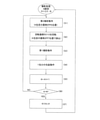
- the second imaging operation is performed in a state where the drug in the Kth package (K is a natural number and the maximum value is the number of packages set to N) is located at the drug imaging position P6 (S1).
- the drug in the K-th package according to this prescription passes from the drug discharge position P7 through the drug package introduction member 7 and the opening of the packing paper S.
- Dropped in the mouth (S2) The situation of this drop is photographed by the above-mentioned first photographing operation (S3). That is, with only the light emitting unit (a) turned on, the above-mentioned upper region is photographed by the residual detection camera (A).
- the residual detection imaging for the K-pack drug of this prescription will start from the first imaging operation (S3). Further, when it is determined from the result of the first photographing operation that the drug does not adhere to the inner wall of the drug packaging introduction member 7, the package corresponding to the K-th drug is packaged while being packaged. When the K package is packaged with a part of the target drug moved to the position of the subsequent K + 1 package, the drug residue in the opening of the packing paper S in the next second photographing operation is performed. Will be detected.
- the packaging operation for one package is executed (S4).
- K is incremented (S5), it is determined whether or not K exceeds N (S6), and if K does not exceed N, the procedure proceeds to the second imaging operation in the subsequent packaging of the drug (S1). ), If K exceeds N, K is reset (S7), and the imaging process for the next prescription package is performed.
- the third camera 66 is located below the residual drug confirmation position P8.
- the third camera 66 takes a picture of the inside of the storage unit 50 which has moved to the residual drug confirmation position P8 after the drug stored in the storage unit 50 is passed to the drug packaging unit 45.
- the third camera 66 is a mirror 66a that laterally reflects an image of the inner peripheral surface of the tubular portion 50a of the storage portion 50 located at the residual charge confirmation position P8, and an image reflected by the mirror 66a. It is provided with an image sensor (CCD, CMOS, etc.) 66b that receives light, various lenses that form an image on the image sensor 66b, and the like.
- an image sensor CCD, CMOS, etc.
- a lower illumination unit 67 is provided at a position above the mirror 66a. Based on the shooting result of the third camera 66, it is possible to automatically or visually check the image of the inspector whether or not the drug remains in the inner wall surface and the inner space of the tubular portion 50a.
- the printing mechanism having the ink ribbon cassette 401 prints characters such as the patient name, morning, noon, and evening before the drug is packaged, and even if an error is determined by the drug identification process or automatic inspection, The error information cannot be printed on the corresponding packing paper portion that has been packaged with the drug. Therefore, a post-printing unit for printing error information such as a mark indicating a defect or a number indicating the number of insufficient chemicals is installed on the packing paper portion in which the chemicals have been packaged through the heater rollers 45d and 45e. It may have been done.
- the method of checking the print layout via the monitor of the drug packing device 1 or the print layout is checked based on the actually printed packing paper.
- the method can be considered.
- the image output unit 81 of the controller 8 performs a process of storing images taken by the first to third cameras 61, 62, 66 and the like in the storage unit 80. Further, the image output unit 81 can read the captured image or the like from the storage unit 80 and display it on the monitor as an inspection support image. The inspector can inspect the drug in the reservoir 50 by looking at the inspection support image displayed on the monitor.
- the image of the specific shot may be an image in which the marking or the like can be recognized by the drug check unit 82.
- FIG. 14 shows an example of the inspection support image. In this image, patient information, information on the drug administered to the patient (drug name and drug image), and front and back images of each drug obtained by cutting out individual drug image parts from the entire image in the reservoir taken for each packet. it's shown.
- the drug check unit 82 recognizes a mark such as a stamp which is drug information of the drug in the photographed images taken in the first imaging process and the third imaging process to determine the drug. be able to. Further, the drug check unit 82 determines that the specified drug and the drug mark indicated by the prescription information (packaging data) in the storage unit 80 (drug master table) match, and thus in the storage unit 50. It is also possible to automatically determine whether or not the drug specified in the prescription information (packaged data) exists.
- a mark such as a stamp which is drug information of the drug in the photographed images taken in the first imaging process and the third imaging process to determine the drug. be able to. Further, the drug check unit 82 determines that the specified drug and the drug mark indicated by the prescription information (packaging data) in the storage unit 80 (drug master table) match, and thus in the storage unit 50. It is also possible to automatically determine whether or not the drug specified in the prescription information (packaged data) exists.
- the drug check unit 82 has other drug information (area (size) of the drug in a plan view, a shape of the drug in a plan view, and a drug, which are the characteristics of each drug obtained by the above-mentioned imaging. Judge all or part of the surface color of. Further, the drug check unit 82 includes the characteristic data (area (size) of the drug in a plan view) of each drug shown by the drug information and the prescription information (packaging data) in the storage unit 80 (drug master table). Whether or not the drug specified in the prescription information (packaging data) exists in the reservoir 50 by determining the degree of agreement between the shape of the drug in a plan view and the surface color of the drug (all or part). It can also be automatically determined.
- the drug check unit 82 compares the image of the photographed drug (drug information) with the image of the reference image (characteristic data of each drug) of each drug stored in the storage unit 80 in advance. It is also possible to automatically determine whether or not the drug specified in the prescription information (packaging data) exists in the storage unit 50 by the image-to-image matching for determining the degree of matching.
- the reference image (for matching between images) used in the drug check unit 82 does not have to be the same as the reference image (for visual recognition) in the above-mentioned inspection support image.
- the adhesion determination unit 83 of the controller 8 introduces the drug package based on the images taken by the first, second, and third residual detection cameras 601, 602, and 603 and the images taken by the third camera 66. It is determined that the drug adheres to the inner wall of the member 7 and the drug adheres to the inner wall of the tubular portion 50a of the storage portion 50.
- the adhesion determination unit 83 has an image taken by the third camera 66 with respect to the cylinder portion 50a of the storage portion 50 located at the residual drug confirmation position P8, and a state in which the drug does not adhere to the inner wall surface. By comparing with the basic image taken in 1), it is determined that the drug adheres to the inner wall surface of the tubular portion 50a.
- the basic image is, for example, an image taken immediately before the first packaging process of the day is performed, and this image is stored in the storage unit 80.
- the drug for example, when the number of pixels whose brightness values match each other or within a predetermined range for each pixel of the image sensor is less than a predetermined ratio with respect to the total number of pixels, the drug. Is determined to be attached to the inner wall of the tubular portion 50a of the storage portion 50.
- the controller 8 can output an alert when it is determined that the drug is attached to the inner wall of the tubular portion 50a of the storage portion 50.
- the drug packaging process may be continued or interrupted.
- the controller 8 may store the photographed image when it is determined that the drug is attached to the inner wall of the tubular portion 50a of the storage portion 50 in the storage unit 80.
- the timing control unit 84 of the controller 8 corresponds to the rotation operation of the rotary plate unit 5010 of the chemical receiving plate unit 501, and the first, second and third cameras 61, 62, 66, first and second And the shooting timing of the third residual detection cameras 601, 602, 603, the lighting timing of the upper lighting unit 63, the lower lighting unit 64, the surface light emitting member 65, and the like are controlled.
- Second and third residual detection cameras 601, 602, 603), and the residual drug confirmation position P8 (third camera 66), still imaging is executed simultaneously. Further, the timing control unit 84 executes shooting in the order of, for example, the first shooting process, the second shooting process, and the third shooting process. Of course, the shooting order can be other than this. Further, the timing control unit 84 can also control the lighting timing of the upper lighting unit 63 and the lower lighting unit 64, the timing of switching the light intensity, and the like in the shooting.
- the timing of photographing the remaining drug confirmation position P8 with the third camera 66 is illustrated below. 1. 1. The remaining drug confirmation position P8 is photographed at the timing when the storage unit 50 moves to the drug discharge position P7. 2. 2. After the storage unit 50 moves to the drug discharge position P7 (after a predetermined time (1 second) after the movement, etc.), the remaining drug confirmation position P8 is photographed.
- the third camera 66 is also possible to place the third camera 66 at the drug discharge position P7 and check the remaining drug.
- the image is taken at the timing after the storage unit 50 moves to the drug discharge position P7 (after a predetermined time (1 second) after the movement, etc.).
- the engraving or the like of the drug located with the engraved surface facing upward can be photographed by the first photographing process, and the engraving or the like can be photographed by the third photographing process. It is possible to take a picture of the stamp or the like of the drug located with the surface marked with the above facing down. This makes it possible to identify the drug in the reservoir based on the images obtained in the first and third imaging processes even for the drug with a stamp or the like on only one side.
- the number of drugs can be determined from the shadow image of the drug obtained by the second imaging process. That is, it is possible to make the imaging location for photographing the stamp of the drug and the imaging location for determining the number of agents the same, and the drug imaging process can be performed quickly. In addition, it is also possible to make an embodiment in which only one of the first photographing process and the third photographing process is performed.
- the timing control unit 84 executes each imaging process a plurality of times for the drug (same subject) in the specific storage unit 50.
- This imaging process does not mean that the first imaging process and the third imaging process are executed once (twice in total), but the first imaging process and the third imaging process are executed a plurality of times, respectively.
- the time required for taking the picture of the drug becomes long.
- a plurality of images are obtained, so that an image in which the engraved surface or the printed surface of the drug faces toward the camera is stochastically obtained. It becomes easy to be printed, and the recognition rate of the stamp or the like can be increased.
- the third camera 66 it is possible to detect the drug adhering to the inner wall surface of the cylinder portion 50a, and to notify the user that the packaged drug may not be as per the prescription information (packaging data). It will be possible.
- a cleaning member 55 for cleaning the top of the drug receiving bottom portion 5012 is provided at a position on the bottom surface side of the turntable portion 5010 that does not form the storage portion 50.
- the cleaning member 55 can prevent the drug powder (drug waste) on the drug receiving bottom 5012 from being packaged together with the drug.
- the cleaning member 55 includes, for example, a scraper 55a and a support portion 55b that supports the scraper 55a.
- the support portion 55b may be movably supported by the turntable portion 5010 so that the scraper 55a can be contacted and separated from the medicine receiving bottom portion 5012.
- the drug receiving bottom portion 5012 rotates about the shaft 504 in a state where the drug receiving bottom portion 5012 is in contact with the drug receiving bottom portion 5012, the drug powder on the drug receiving bottom portion 5012 is caused by the scraper 55a to cause the storage recess 5012b described later. And it is attracted to the chemical powder collection groove 5012c.
- a cleaning switching operation unit 501d (see FIG. 17) is inserted in the annular gap portion.
- the cleaning switching operation unit 501d has a plurality of holes to be inserted into the guide pillar 501g, and these holes allow linear movement in the axial direction of the shaft 504 and are integrated with the rotary disk unit 5010. It can rotate around the axis 504.
- the cleaning switching operation portion 501d is formed with a notch portion 501k (see FIG. 17) through which the connecting rib portion 501f is passed.
- the support plate portion 501h of the rotary plate portion 5010 is located below the cleaning switching operation portion 501d.
- the support plate portion 501h is a member located on the center side of the turntable portion 5010 and fixed to the turntable portion 5010.
- the support plate portion 501h is shown by a virtual line in FIGS. 17 and 18.
- a coil spring 501j is arranged between the cleaning switching operation unit 501d and the support plate unit 501h, and the cleaning switching operation unit 501d is urged upward by the coil spring 501j.
- the cleaning switching operation unit 501d is moved downward.
- the downward movement of the cleaning switching operation unit 501d is performed by the motor 5060.
- the motor 5060 and the support mechanism 5061 that supports the motor 5060 are attached to the upper plate portion 51.
- the motor 5060 may be installed at a position other than the central position of the support mechanism 5061.
- the cleaning member 55 has a shaft portion 553.
- the shaft portion 553 is rotatably supported by a bearing portion 554 provided on the support portion 55b. Further, a gear portion 552 meshed with the rack portion 551 is fixed to one end side of the shaft portion 553.
- the cleaning switching operation portion 501d is lowered by the drive of the motor 5060 during cleaning, the rack portion 551 is lowered, the gear portion 552 is rotated, and the shaft portion 553 is rotated, as shown in FIG.
- the scraper 55a fixed to the shaft portion 553 rises when the shaft portion 553 rotates, and the edge portion of the scraper 55a comes into contact with the drug receiving bottom portion 5012.
- the reverse rotation of the motor 5060 executes the reverse operation of the above operation.
- the drug packaging device 1 packages the drug supplied from the drug supply unit (drug storage / dispensing unit 11) for supplying various drugs and the drug supplied from the drug supply unit by the packaging paper S.
- the drug packaging device 1 may be configured to include the cleaning device without the photographing unit 60.
- the cleaning device it may be possible to switch between a state in which the edge portion of the cleaning member 55 (scraper 55a) is raised and a state in which the edge portion is in contact with the drug receiving bottom portion (5012).
- the drug packaging device 1 can rotate linearly with the rotary disk portion 5010 and can move linearly in the axial direction of the shaft 504 that rotationally supports the rotary disk portion 5010, and moves linearly in the axial direction of the shaft 504.
- a cleaning switching operation unit 501d that switches between a state in which the cleaning member 55 is in contact with the drug receiving bottom portion 5012 and a state in which the cleaning member 55 is not in contact with the cleaning member 55, and a drive unit (motor 5060 and support mechanism 5061) that moves the cleaning switching operation unit 501d in the axial direction of the shaft 504. Etc.) and.
- the drug receiving bottom portion 5012 may be rotatable as described later.
- the cleaning switching operation unit 501d for switching the cleaning operation of the cleaning member 55 is attached to the rotary disk unit 5010 side, and the motor 5060 and the support mechanism 5061 for operating the cleaning switching operation unit 501d are on the upper plate. It is attached to the portion 51. That is, since the drug receiving board 501 itself of the drug storage unit 5 does not have a drive system, the drug receiving board 501 can be easily removed from the drug packaging device 1.
- the drug receiving board portion 501 may be removed as a whole including the drug receiving bottom portion 5012, or may be performed in a component portion not including the drug receiving bottom portion 5012.
- the medicine receiving bottom portion 5012 can be removed from the lower plate portion 52 and washed.
- the user grasps the handle 505 and raises the upper plate portion 51 (including the motor 5060, the support mechanism 5061, etc.) to expose the upper surface side of the drug receiving board portion 501.
- the drug receiving board portion 501 can be separated from the shaft 504 (square convex portion 504a).
- the scraper 55a (shaft portion 553) extends from the outer peripheral side of the turntable portion 5010 to the center side of the turntable portion 5010.
- the end side of the scraper 55a located on the center side is eccentrically located on the side lagging from the center of the turntable portion 5010 with respect to the forward rotation direction of the turntable portion 5010.
- the drug powder is removed from the drug receiving bottom portion 5012 when the rotating disk portion 5010 is rotated. Therefore, it is possible to eliminate the trouble of the user cleaning the top of the drug receiving bottom 5012. Then, without such trouble, the problem that the medicine powder in the storage portion 50 located at the medicine imaging position P6 does not properly illuminate, the problem that the lump of the medicine powder is mistaken for one medicine, and the like are solved. Can be resolved.
- the cleaning of the drug powder by the cleaning member 55 may be automatically performed each time the person to be prescribed the drug changes.
- the above-mentioned chemical powder cleaning may be automatically performed each time the packaging process for the set number of packages (for example, 10 packages) is completed.
- the above-mentioned chemical powder cleaning may be performed when the dirt on the bottom of the storage portion 50 located at the chemical imaging position P6 is detected by a sensor or an image captured by a camera, or when the user presses the cleaning switch. .. If it is determined that cleaning is necessary, the supply of the drug to the storage section 50 may be stopped, and all the drugs existing in the storage section 50 at that time may be packaged. However, if there is only one type of prescription drug in the morning, noon, and evening (it can be determined from the prescription information), there is no problem even if the drug and its powder are packaged together, so the necessity of cleaning is determined. It may or may not be present.
- the drug powder collected by the cleaning member 55 may be stored in the storage recess 5012b (see FIG. 10) of the drug receiving bottom 5012.
- the cleaning member 55 may be provided so as to drop from the packaging opening 5012a.
- the drug powder dropped from the packaging opening 5012a may be packaged in the packing paper S located below the packaging opening 5012a. That is, the drug powder of the drug receiving bottom 5012 may be collected by the cleaning member 55 and packaged in the packing paper S. For example, after the packing paper from which the medicine has been dropped is sealed from the packaging opening 5012a and the medicine packing is completed, the unwrapped portion of the packing paper is moved under the packaging opening 5012a.
- the dimming member may be made translucent.
- the upper lighting unit 63 and the lower lighting unit 64 can adjust the amount of light. Then, when it is possible to know whether or not the currently stored drug indicated by the prescription information (packaging data) is stamped, the amount of light at the time of photographing the stamped drug may be smaller than the amount of light for the non-marked drug. By reducing the amount of light when the engraving agent is photographed, it is possible to suppress an event in which the shadow of the engraving disappears and becomes unrecognizable due to the excessive amount of light.
- the amount of light means the total amount of light flux passing through a certain surface within a certain time.
- the light amount adjustment is an increase / decrease in the luminous flux from the illumination units 63, 64 to the storage unit 50, and is an increase / decrease in the luminous flux of each LED by, for example, a pulse width modulation process of an applied voltage to the LEDs constituting the illumination units 63, 64. This can be done by increasing or decreasing the total amount of luminous flux to the storage unit 50 by increasing or decreasing the number of LEDs lit.
- simultaneous shooting with the combination may be executed.
- the light amount adjustment of the above illumination is performed in two stages of the first light amount and the second light amount having a light amount smaller than the first light amount, and the chemical photographing is performed, for example, by the first photographing process at the first light amount ⁇ the second light amount.
- the first imaging process ⁇ the second imaging process ⁇ the third imaging process with the first light intensity ⁇ the third imaging process with the second light intensity may be executed in sequence.
- the shutter speed of the first and second cameras at the time of photographing the engraving agent may be faster than the shutter speed for the non-engraving agent. By adjusting the shutter speed in this way, it is possible to obtain the effect of suppressing the phenomenon that the shadow of the engraving disappears and becomes unrecognizable, as in the case of adjusting the amount of light.
- the first imaging process, the second imaging process, and the third imaging process are performed at one location of the drug imaging position P6, but the present invention is not limited to this, and the above is not limited to the above.
- the first imaging process, the second imaging process, and the third imaging process may be performed.
- the processing of the controller 8 causes all of the plurality of drugs in one package (same package) to be stored together in one storage unit 50, and the above-mentioned imaging is performed. Not limited to.
- all of the plurality of drugs for one package are not stored together in one storage unit 50, but a plurality of drugs for one package are spatially or temporally stored in another storage unit 50.
- the drug may be shared and stored, and the shared storage imaging may be performed in which the above-mentioned imaging is performed on the drug (less drug) shared and stored in this way.
- the shared storage condition indicating whether or not a plurality of drugs in the same package should be shared and stored is stored in the sorting information unit 88 of the controller 8.
- the controller 8 determines that a plurality of drugs in the same package should be shared and stored based on the shared storage conditions stored in the sorting information unit 88 (the controller 8 is the sorting determination unit). ), A plurality of drugs in the same package are shared and stored in a plurality of storage units 50, and drug imaging processing, drug dispensing processing, etc. are performed.
- the controller 8 transfers the plurality of medicines for one packet in a plurality of (for example, two) storage portions 50.
- the above-mentioned imaging is performed at one or more drug imaging positions.
- the drug discharge position P7 packing position
- the drug is packaged in a packing paper, so that the plurality of drugs in the same package are finally packaged together.
- the controller 8 when a plurality of drugs in the same package are composed of A, B, C, and D, the controller 8 operates a cassette a containing the drug A and a cassette b containing the drug B to operate one storage unit 50.
- the drugs A and B are stored in the container A and B, and then the cassette c for storing the drug C and the cassette d for storing the drug D are operated to store the drugs C and D in the next storage unit 50.
- the controller 8 sequentially performs imaging on the one storage unit 50 and imaging on the next storage unit 50 at the drug imaging position P6.
- the controller 8 stores the plurality of drugs for one package in one storage unit 50 at different times, and the drugs are stored.
- the above shooting is performed at the shooting position P6 at different times.
- the one storage unit 50 passes through the drug discharge position P7 (packaging position) a plurality of times due to the multiple rotations of the turntable unit 5010, so that all of the plurality of drugs for one package stop moving. Dropped in the packing paper inside.
- the plurality of drugs for each package are used as described above. You may take a shared storage image as you like. That is, regardless of whether or not one package is a package at the time of one dose, a plurality of drugs that are packaged in the same package are stored and photographed as described above.
- the drug imaging device 6 can also be defined as a device including a drug imaging unit and the drug sorting unit for the above-mentioned shared storage.
- the drug imaging unit is, for example, an imaging unit 60 that photographs the drug in the storage unit 50.
- the drug sorting unit includes, for example, a drug storage unit 5 and a controller 8 for sharing and storing a plurality of drugs in the same package in the storage unit 50.
- the shared storage of drugs in the above shared storage photography can also be performed as follows.
- Shared storage of drugs is performed so that the number of drugs stored in the same storage unit 50 does not exceed the set number (for example, 2).
- Drugs that are registered as similar to each other in the drug master table are stored in a shared manner so that they are not stored in the same storage section 50 (similar drugs are photographed separately).
- one drug A is stored in one storage section 50
- one drug A'(A ⁇ A') similar to another storage section 50 is stored.
- the drug B (B ⁇ A, B ⁇ A') is included, the drug B may be stored together with the drug A or the drug A'(drug A and the drug A'are photographed separately. ).
- Information registered as similar to each other in the drug master table is not always essential. Whether there is a similar drug among the drugs corresponding to the prescription information for each prescription information using the reference image or feature data (either size, shape, color, or a combination thereof) stored in the drug master table as a reference.
- the drug may be shared and stored at the discretion.
- the drug of the same type is separated from the drug of another drug type, and the drug is shared and stored so as to be stored in the same storage unit 50. For example, two drugs A are stored in one storage section 50, and drug B (A ⁇ B) is stored in another storage section 50. (4) Shared storage of the drug is performed so that the storage section 50 is divided according to the difference in the supply source of the drug.
- the drug supplied by hand and the drug supplied in a cassette are separately stored in separate storage units 50. Further, for example, the drug supplied in the cassette and the drug supplied in the universal cassette may also be stored separately in the separate storage unit 50.
- Drugs are shared and stored so that the number of drugs exceeding the number of drugs that can be inspected in one inspection is not stored in the same storage unit 50. This number increases when the area of the bottom of the storage unit 50 is large, and decreases when the area of the bottom of the storage unit 50 is small. It should be noted that if the ratio of the total area (projected area) of each drug in plan view to the bottom area of the storage unit 50 is larger than the threshold value, instead of the number of drugs, the shared storage may be performed. good.
- the shared storage conditions of (2) to (7) and the set number of (1) above, which indicate whether or not the shared storage of drugs should be executed based on the set number of drugs and the presence or absence of similar drugs, are sorted by the storage unit 80. It is stored in the information unit 88.
- information on the presence or absence of the similar drug used as a condition for execution and the drug type of the similar drug is stored in advance in the storage unit 80 (drug master table).
- drug master table information about the mark and / or both of the reference image and feature data (size, shape, color) are registered for each drug, and as described above, the presence or absence of similar drugs is registered. And the type information of the similar drug is registered.
- the area (size) of the drug in a plan view, the shape of the drug in a plan view, the surface color of the drug, and the like can be used as criteria for registering the drug as a similar drug in the drug master table.
- Similar drugs include drugs determined by human judgment as similar drugs, as well as drugs mechanically selected by a similarity determination algorithm based on a predetermined similarity criterion. Further, whether or not the same type of drug is present in one package is determined based on the prescription information (separate package data). Further, the distinction between the medicine to be hand-sprayed and the medicine to be supplied to the cassette can be grasped by the controller 8 from the storage information of the medicine for each cassette and the usage setting information of the hand-spreading unit 13.
- the controller 8 functions as a sorting determination unit using the information in the sorting information unit 88.
- the controller 8 drug packaging device
- the controller 8 is capable of prescription-based packaging processing.
- the characteristics of at least two types of drugs are similar among the drugs packaged in the same package (see (2) above).
- different types of drugs are included in the drugs packaged in the same package (see (3) above)
- the drug packaged in the same package includes a drug supplied to the storage unit 50 via a manual drug charging operation by a person and a drug supplied via a drug cassette ((4) above). reference)
- a drug whose characteristic data (including a reference image) is not registered in the storage unit 80 is included in the drugs packaged in the same package (see (6) above). If it is determined that the combination of at least one of the cases or a plurality of cases is applicable, the shared storage is executed.
- the controller 8 (drug packaging device) photographs an unregistered drug stored in the storage unit 50 and registers the image as a reference image in the drug master table (see (6) above).
- the drug is treated as a registered drug and the unregistered drug is not shared and stored (see (6) above).
- the drug is dispensed as follows. ( ⁇ ) If the drug to be paid out by prescription is contained in a cassette, it is paid out from the cassette. ( ⁇ ) If the drug to be dispensed by prescription is not contained in the cassette and the drug can be dispensed from the universal cassette, the drug is dispensed from the universal cassette.
- the case where the drug can be dispensed from the universal cassette is a case where the drug is compatible with the universal cassette and the universal cassette is not set to the mode for dispensing other drugs. ( ⁇ ) If the drug cannot be dispensed from the universal cassette, the drug is dispensed from the hand-spraying unit 13.
- the three drugs A, B, and C are shared and stored in each of the three storage units 50. Even in this case, as described above, it is conceivable to perform the comparison process a total of 6 times without narrowing down the matching target. These can be said to be comparative processes (automatic drug identification processes) performed without narrowing down the matching targets for the drugs in the shared storage section 50.
- the drugs A, B, and C shown in the packaged data are not always stored, and there is a possibility that the drug CC is stored instead of the drug C due to a malfunction.
- the matching target for the drug in the storage section 50 is used. It is possible to narrow down the number and improve the efficiency of the automatic drug identification process.
- the content of the sorting information of the four drugs is "One drug in the 15th drug cassette and one drug in the 18th drug cassette are stored in the storage section at the first drug receiving position P1 and the turntable section 5010. After turning 45 degrees forward, one drug in the 19th drug cassette and one drug in the 20th drug cassette are stored in the storage section of the first drug receiving position P1.
- the specified storage unit 50 is associated with the drug name of the 15th drug cassette and the drug name of the 18th drug cassette. Can be done. Then, the storage unit 50 reaches the drug imaging position P6, and the drug image (drug information) imaged there is the characteristic data of the drug derived from the drug name of the 15th drug cassette and the drug name of the 18th drug cassette (reference). By associating (including images), it means that the matching target has been narrowed down.
- the matching target for the drugs in the storage unit 50 can be narrowed down.
- 6 times of comparison processing ⁇ 5 times ⁇ 4 times ⁇ 3 times ⁇ 2 times ⁇ 1 time comparison processing is performed, so 21 times of comparison processing is required. ..
- the matching target for the drugs in the storage unit 50 is narrowed down and each storage unit is stored. Since the comparison process is performed 6 times for 50 3 drugs, a total of 12 comparison processes can be performed.
- the shared storage is performed based on the drug sorting information, and the drug is photographed.
- the candidate of the characteristic data (reference image) of the drug to be compared with the captured drug image (drug information) is selected from the drug sorting information, the drug in the storage unit 50 is matched. It is possible to narrow down the target and improve the efficiency of the automatic drug identification process. With such a configuration, it is possible to obtain the advantages of reducing the overlap of drugs due to the reduction in the number of drugs in the storage unit 50 and improving the efficiency of the automatic drug identification process.
- the above 6 drugs are stored one by one using the 6 storage units 50 and the above drug sorting information is stored and used, 1 in the captured image in each storage unit 50 is used. Based on the above-mentioned drug sorting information, one drug image portion can be compared with the characteristics of the drug on a one-to-one basis six times.
- the number of times of photographing for the storage unit 50 increases, and the processing time required for the packaging becomes long.
- the number of drugs stored at the same time is, for example, two
- the number of times of photographing the three drugs A, B, and C can be reduced to two.
- the number of times the drug is photographed is 2.
- the number of drugs in the same package is 5, the number of times the drug is photographed is 3 times.
- the above-mentioned drug sorting information is associated with the photographed image of the sharedly stored drug.
- the controller 8 distributes and dispenses the medicine corresponding to one dosing time to a plurality of storage units 50 as described below according to a specific standard. Specific criteria are ( ⁇ ) When two of the drugs corresponding to the time of administration are related to similar drugs ( ⁇ ) When different drugs are included (Each drug of the same type is discharged to the same reservoir) ( ⁇ ) There are three points when the supply source for discharging the drug includes the hand-spraying portion 13 and the drug cassette. Further, the controller 8 identifies a candidate for a reference image to be used for comparison with the drug included in the captured image based on the above sorting information (narrows down the matching target of the drug).
- the drug existing in the storage unit 50 is a specific drug supplied from a specific cassette such as the drug storage / dispensing unit 11, and the information of the drug in the captured image is the above-mentioned specific drug. Since it is sufficient to compare with the drug information, the drug information to be compared is narrowed down. In particular, since it is possible to narrow down the matching target to be compared to one similar drug, which is difficult to distinguish only from the captured image, there is an advantage that the drug can be quickly identified and misidentification is unlikely to occur. That is, with such a configuration, the advantages of reducing the overlap of drugs by reducing the number of drugs in the reservoir 50, improving the efficiency of the automatic identification process, and suppressing misidentification of similar drugs can be obtained.
- the standard for automatic inspection of the hand-sprinkled drug and the cassette supply are used. It is also possible to make the criteria for automatic inspection of drugs different from each other. For example, the threshold value of the degree of agreement in the affirmative determination for the drug supplied by hand is higher than the threshold value for the drug supplied in the cassette.
- the inspection method may be switched between the hand-sown supply and the cassette supply. For example, for drugs supplied by hand, a visual inspection is performed by an inspector on the captured image, and for drugs supplied on a cassette, automatic inspection is performed by identification processing using captured images, based on the experience that there are few errors. Will be.
- the drug powder dropped from the packaging opening 5012a is packaged by the packing paper S located below the packaging opening 5012a, but the cleaning method is not limited to this. According to the cleaning method shown below, the consumption of the packing paper S due to the cleaning of the chemical powder can be reduced.
- the cleaning method shown below the consumption of the packing paper S due to the cleaning of the chemical powder can be reduced.
- the drug powder-containing packaging is formed in the middle of the continuous packaging bandage. For example, in the case of long-term packaging in which the prescription drugs for morning, noon, and evening are only the same species, it is considered that there is no particular problem even if the drug powder produced by this packaging process enters together with the drug. Therefore, in such a case, the chemical powder cleaning may not be performed. Whether or not the prescription drugs in the morning, noon, and evening are of the same type can be determined from the prescription information.
- the relay unit 71 and the drug powder recovery box 74 may be moved manually or by an actuator such as a motor. Further, as an example, a support member that supports the relay unit 71 and the drug powder recovery box 74 is rotatably supported in a horizontal plane by a vertical axis, and the positions of the relay unit 71 and the drug powder recovery box 74 are displaced by this rotation. A switching mechanism may be adopted. Further, for example, the support member may be provided with a gear portion (rack portion), and the support member may be rotated by being driven by a drive gear meshed with the gear portion. Further, the drug powder recovery box 74 is removable from the support member, and the accumulated drug powder can be disposed of at a predetermined place.
- the relay unit 71 When the relay unit 71 is configured to be manually removable, for example, a magnet is placed at a predetermined position of the relay unit 71 so that an error in the arrangement orientation does not occur when the relay unit 71 is reattached to the shooter unit 72. While positioning the N pole of the magnet and arranging the S pole at a position that is, for example, 180 degrees away from this N pole, the S pole of the magnet is positioned at the proper mounting position of the mounting portion of the relay portion 71 of the drug packaging introduction member 7. Similarly, the S pole may be arranged at a position 180 degrees away from the N pole.
- the magnet on the mounting portion side and the magnet on the relay portion 71 side are attracted and positioned, while the relay portion 71 is mounted in an improper orientation. Since the magnet on the mounting portion side and the magnet on the relay portion 71 side repel each other, it can be seen that the mounting direction of the relay portion 71 is not appropriate.
- a slit portion is formed on a part of the side surface of the relay portion 71, and by introducing the ions emitted by the ionizer into the relay portion 71 from the slit portion, the chemical does not adhere to the relay portion 71 or the like due to static electricity. You may do so. In such a configuration, it is necessary to prevent the position of the slit portion from being opposite to the normal position, and the arrangement structure of the magnet that shows whether or not the mounting direction of the relay portion 71 is appropriate is useful.
- a concave portion or a convex portion is provided on the outer peripheral portion of the relay portion 71, while a convex portion or a concave portion is provided on the mounting portion of the relay portion 71, and if the mounting direction of the relay portion 71 is not appropriate, uneven fitting is provided.
- a structure may be adopted in which uneven fitting can be performed only when the relay portion 71 cannot be fitted and the mounting direction of the relay portion 71 is appropriate.
- the relay portion 71 of the chemical packaging introduction member 7 is lateral to the shooter portion 72 below the relay portion 71.
- the relay portion 71 is provided with a bottom portion 71a that can be opened and closed while moving in the direction.
- the bottom portion 71a is made of, for example, a disk-shaped member having a diameter equal to or larger than the outer diameter of a cylinder in the relay portion 71, and can be opened and closed by being rotated by the vertical axis portion 71b. This opening and closing may be performed manually or by an actuator such as a motor.
- the bottom 71a is closed at the relay unit 71. After cleaning, the relay unit 71 is moved laterally.
- a drug powder recovery box 74 is arranged below the relay unit 71 that has moved laterally. By opening the bottom 71a of the relay unit 71 that has moved laterally, the collected drug powder can be dropped into the drug powder collection box 74. After discarding the chemical powder, the relay section 71 is returned to the position on the shooter section 72.
- the structure is such that the drug receiving bottom portion 5012 can be rotated, it is advantageous to eliminate the overlap of the drugs in the storage section 50.
- the overlap of chemicals in the reservoir 50 is eliminated by the forward / reverse rotation of the rotating disk portion 5010 within a predetermined range driven by the motor 503, but the rotation of the rotating disk portion 5010. If the range is small, the medicine located in the center of the storage portion 50 may not hit the wall surface of the cylinder portion 50a, and the overlap of the medicines may not be eliminated. Therefore, the drug receiving bottom portion 5012 may be rotated in the direction opposite to the rotation direction of the turntable portion 5010 even during the process of eliminating the overlap of the drugs.
Landscapes
- Engineering & Computer Science (AREA)
- Mechanical Engineering (AREA)
- Health & Medical Sciences (AREA)
- General Health & Medical Sciences (AREA)
- Quality & Reliability (AREA)
- General Physics & Mathematics (AREA)
- Physics & Mathematics (AREA)
- Chemical & Material Sciences (AREA)
- Life Sciences & Earth Sciences (AREA)
- Biochemistry (AREA)
- Immunology (AREA)
- Analytical Chemistry (AREA)
- Pathology (AREA)
- Computer Vision & Pattern Recognition (AREA)
- Veterinary Medicine (AREA)
- Radiology & Medical Imaging (AREA)
- Nuclear Medicine, Radiotherapy & Molecular Imaging (AREA)
- Medical Informatics (AREA)
- Medicinal Chemistry (AREA)
- Pharmacology & Pharmacy (AREA)
- Animal Behavior & Ethology (AREA)
- Public Health (AREA)
- Theoretical Computer Science (AREA)
- Medical Preparation Storing Or Oral Administration Devices (AREA)
- Basic Packing Technique (AREA)
- Investigating Materials By The Use Of Optical Means Adapted For Particular Applications (AREA)
- Image Analysis (AREA)
- Control And Other Processes For Unpacking Of Materials (AREA)
- Medical Treatment And Welfare Office Work (AREA)
- Auxiliary Devices For And Details Of Packaging Control (AREA)
Priority Applications (11)
| Application Number | Priority Date | Filing Date | Title |
|---|---|---|---|
| CN202180055302.7A CN116113577B (zh) | 2020-09-03 | 2021-09-03 | 药剂拍摄装置和药剂分包装置 |
| KR1020237008195A KR20230058644A (ko) | 2020-09-03 | 2021-09-03 | 약제 촬영 장치 및 약제 분포 장치 |
| CA3191522A CA3191522A1 (en) | 2020-09-03 | 2021-09-03 | Drug imaging device and drug packaging device |
| US18/043,897 US12138228B2 (en) | 2020-09-03 | 2021-09-03 | Drug imaging device and drug packaging device |
| EP21864423.5A EP4173974A4 (en) | 2020-09-03 | 2021-09-03 | DRUG IMAGING DEVICE AND DRUG PACKAGING DEVICE |
| JP2022546979A JP7730034B2 (ja) | 2020-09-03 | 2021-09-03 | 薬剤撮影装置および薬剤分包装置 |
| CN202511718340.2A CN121650953A (zh) | 2020-09-03 | 2021-09-03 | 药剂拍摄装置和药剂分包装置 |
| AU2021337390A AU2021337390A1 (en) | 2020-09-03 | 2021-09-03 | Drug imaging device and drug packaging device |
| US18/915,274 US12582577B2 (en) | 2020-09-03 | 2024-10-14 | Drug imaging device and drug packaging device |
| JP2025022606A JP2025072638A (ja) | 2020-09-03 | 2025-02-14 | 薬剤分包装置および薬剤受け底部 |
| JP2025062060A JP2025096391A (ja) | 2020-09-03 | 2025-04-03 | 薬剤分包装置 |
Applications Claiming Priority (4)
| Application Number | Priority Date | Filing Date | Title |
|---|---|---|---|
| JP2020-148162 | 2020-09-03 | ||
| JP2020148162 | 2020-09-03 | ||
| JP2021139595 | 2021-08-30 | ||
| JP2021-139595 | 2021-08-30 |
Related Child Applications (2)
| Application Number | Title | Priority Date | Filing Date |
|---|---|---|---|
| US18/043,897 A-371-Of-International US12138228B2 (en) | 2020-09-03 | 2021-09-03 | Drug imaging device and drug packaging device |
| US18/915,274 Continuation US12582577B2 (en) | 2020-09-03 | 2024-10-14 | Drug imaging device and drug packaging device |
Publications (1)
| Publication Number | Publication Date |
|---|---|
| WO2022050371A1 true WO2022050371A1 (ja) | 2022-03-10 |
Family
ID=80492255
Family Applications (1)
| Application Number | Title | Priority Date | Filing Date |
|---|---|---|---|
| PCT/JP2021/032393 Ceased WO2022050371A1 (ja) | 2020-09-03 | 2021-09-03 | 薬剤撮影装置および薬剤分包装置 |
Country Status (9)
| Country | Link |
|---|---|
| US (2) | US12138228B2 (https=) |
| EP (1) | EP4173974A4 (https=) |
| JP (3) | JP7730034B2 (https=) |
| KR (1) | KR20230058644A (https=) |
| CN (2) | CN116113577B (https=) |
| AU (1) | AU2021337390A1 (https=) |
| CA (1) | CA3191522A1 (https=) |
| TW (1) | TWI876091B (https=) |
| WO (1) | WO2022050371A1 (https=) |
Cited By (1)
| Publication number | Priority date | Publication date | Assignee | Title |
|---|---|---|---|---|
| WO2025239450A1 (ja) * | 2024-05-17 | 2025-11-20 | 株式会社湯山製作所 | 分包支援システム |
Families Citing this family (3)
| Publication number | Priority date | Publication date | Assignee | Title |
|---|---|---|---|---|
| WO2025151583A1 (en) * | 2024-01-12 | 2025-07-17 | Parata Systems, Llc | Methods, systems, and computer program product for generating dispense settings and a cell layout configuration for a drug product packaging system based on drug product characteristics |
| CN118430130B (zh) * | 2024-05-22 | 2026-03-27 | 郑州大学 | 一种支持远程问诊和药品精准配发的智能药柜 |
| CN119329810B (zh) * | 2024-12-12 | 2025-04-29 | 江苏宣泰药业有限公司 | 一种可控量的药片自动包装填充装置 |
Citations (5)
| Publication number | Priority date | Publication date | Assignee | Title |
|---|---|---|---|---|
| JP2004290350A (ja) * | 2003-03-26 | 2004-10-21 | Yuyama Manufacturing Co Ltd | 薬剤フィーダ |
| JP2010086257A (ja) * | 2008-09-30 | 2010-04-15 | Shinichi Suguno | 薬剤の撮像記憶装置及び薬剤の撮像台 |
| JP2015002795A (ja) | 2013-06-19 | 2015-01-08 | 富士フイルム株式会社 | 薬剤情報取得装置及び方法 |
| JP2017225832A (ja) * | 2012-01-11 | 2017-12-28 | パナソニックヘルスケアホールディングス株式会社 | 薬剤供給装置 |
| WO2018025852A1 (ja) | 2016-08-05 | 2018-02-08 | 株式会社湯山製作所 | 薬剤分包装置 |
Family Cites Families (25)
| Publication number | Priority date | Publication date | Assignee | Title |
|---|---|---|---|---|
| JP3779364B2 (ja) * | 1996-01-26 | 2006-05-24 | 株式会社湯山製作所 | 薬剤収納取出装置 |
| JP4097759B2 (ja) | 1998-01-20 | 2008-06-11 | 株式会社トーショー | 調剤装置 |
| JP4396913B2 (ja) * | 2003-02-18 | 2010-01-13 | 株式会社トーショー | 連結形薬剤分包機 |
| JP4473170B2 (ja) * | 2005-04-27 | 2010-06-02 | 高園産業株式会社 | 錠剤カセッタ |
| KR100816648B1 (ko) * | 2007-01-19 | 2008-03-26 | (주)제이브이엠 | 반자동 약제 포장기 |
| JP4962320B2 (ja) | 2008-01-11 | 2012-06-27 | 富士通株式会社 | モデル管理装置および記録媒体 |
| US10492991B2 (en) * | 2010-05-30 | 2019-12-03 | Crisi Medical Systems, Inc. | Medication container encoding, verification, and identification |
| JP5430615B2 (ja) * | 2011-06-28 | 2014-03-05 | 株式会社椿本チエイン | 試料載置場所読取装置及びコンピュータプログラム |
| JP5898529B2 (ja) | 2012-03-01 | 2016-04-06 | オオクマ電子株式会社 | 薬剤個数計数装置 |
| JP6009888B2 (ja) * | 2012-09-27 | 2016-10-19 | 富士フイルム株式会社 | 薬剤検査装置及び方法 |
| KR102223436B1 (ko) * | 2012-10-03 | 2021-03-05 | 가부시키가이샤 유야마 세이사쿠쇼 | 약제 감사 시스템, 권취 장치, 조출 장치 및 홀더 |
| KR20140057945A (ko) * | 2012-11-05 | 2014-05-14 | (주)제이브이엠 | 약제 자동 포장장치 |
| JP6232735B2 (ja) | 2013-04-30 | 2017-11-22 | キヤノンマーケティングジャパン株式会社 | 情報処理装置、情報処理装置の制御方法、およびプログラムに関する。 |
| JP5921704B2 (ja) * | 2014-03-10 | 2016-05-24 | 株式会社東芝 | 異物検査装置、異物検査方法、異物検査プログラム |
| WO2016002650A1 (ja) * | 2014-07-01 | 2016-01-07 | 株式会社湯山製作所 | 薬剤払出装置 |
| DK2962956T3 (en) * | 2014-07-03 | 2017-01-23 | Becton Dickinson Rowa Germany Gmbh | Storage container for a device for the automated dispensing of individual drug portions |
| WO2016152731A1 (ja) * | 2015-03-23 | 2016-09-29 | 株式会社湯山製作所 | 薬剤分包装置 |
| JP6229748B2 (ja) * | 2015-03-31 | 2017-11-15 | キヤノンマーケティングジャパン株式会社 | 情報処理装置、錠剤供給システム、制御方法、プログラム |
| KR102602951B1 (ko) * | 2015-06-29 | 2023-11-16 | 가부시키가이샤 유야마 세이사쿠쇼 | 약제 불출 장치 |
| WO2017119276A1 (ja) * | 2016-01-06 | 2017-07-13 | 株式会社湯山製作所 | 鑑査支援システム、錠剤分包装置、分包制御プログラム |
| KR20180016086A (ko) | 2016-08-05 | 2018-02-14 | (주)제이브이엠 | 약제 인출 장치 |
| TWI831775B (zh) * | 2018-06-19 | 2024-02-11 | 日商湯山製作所股份有限公司 | 藥劑分類裝置 |
| CA3097103A1 (en) | 2018-08-28 | 2020-03-05 | Yuyama Mfg. Co., Ltd. | Medicine loading device and medicine recovery method |
| JP7547377B2 (ja) * | 2019-05-03 | 2024-09-09 | アールエックスセーフ エルエルシー | 薬剤包装システム及びパウチ |
| US12043464B2 (en) * | 2020-11-09 | 2024-07-23 | Becton Dickinson Rowa Germany Gmbh | Method and device for producing a blister tube, and blister tube |
-
2021
- 2021-09-03 JP JP2022546979A patent/JP7730034B2/ja active Active
- 2021-09-03 CA CA3191522A patent/CA3191522A1/en active Pending
- 2021-09-03 WO PCT/JP2021/032393 patent/WO2022050371A1/ja not_active Ceased
- 2021-09-03 EP EP21864423.5A patent/EP4173974A4/en active Pending
- 2021-09-03 TW TW110132812A patent/TWI876091B/zh active
- 2021-09-03 CN CN202180055302.7A patent/CN116113577B/zh active Active
- 2021-09-03 US US18/043,897 patent/US12138228B2/en active Active
- 2021-09-03 AU AU2021337390A patent/AU2021337390A1/en active Pending
- 2021-09-03 CN CN202511718340.2A patent/CN121650953A/zh active Pending
- 2021-09-03 KR KR1020237008195A patent/KR20230058644A/ko active Pending
-
2024
- 2024-10-14 US US18/915,274 patent/US12582577B2/en active Active
-
2025
- 2025-02-14 JP JP2025022606A patent/JP2025072638A/ja active Pending
- 2025-04-03 JP JP2025062060A patent/JP2025096391A/ja active Pending
Patent Citations (5)
| Publication number | Priority date | Publication date | Assignee | Title |
|---|---|---|---|---|
| JP2004290350A (ja) * | 2003-03-26 | 2004-10-21 | Yuyama Manufacturing Co Ltd | 薬剤フィーダ |
| JP2010086257A (ja) * | 2008-09-30 | 2010-04-15 | Shinichi Suguno | 薬剤の撮像記憶装置及び薬剤の撮像台 |
| JP2017225832A (ja) * | 2012-01-11 | 2017-12-28 | パナソニックヘルスケアホールディングス株式会社 | 薬剤供給装置 |
| JP2015002795A (ja) | 2013-06-19 | 2015-01-08 | 富士フイルム株式会社 | 薬剤情報取得装置及び方法 |
| WO2018025852A1 (ja) | 2016-08-05 | 2018-02-08 | 株式会社湯山製作所 | 薬剤分包装置 |
Non-Patent Citations (1)
| Title |
|---|
| See also references of EP4173974A4 |
Cited By (1)
| Publication number | Priority date | Publication date | Assignee | Title |
|---|---|---|---|---|
| WO2025239450A1 (ja) * | 2024-05-17 | 2025-11-20 | 株式会社湯山製作所 | 分包支援システム |
Also Published As
| Publication number | Publication date |
|---|---|
| EP4173974A1 (en) | 2023-05-03 |
| US12582577B2 (en) | 2026-03-24 |
| US20250032360A1 (en) | 2025-01-30 |
| KR20230058644A (ko) | 2023-05-03 |
| JP2025072638A (ja) | 2025-05-09 |
| US20230320936A1 (en) | 2023-10-12 |
| TWI876091B (zh) | 2025-03-11 |
| JP2025096391A (ja) | 2025-06-26 |
| CN121650953A (zh) | 2026-03-13 |
| EP4173974A4 (en) | 2024-06-12 |
| AU2021337390A1 (en) | 2023-02-23 |
| JP7730034B2 (ja) | 2025-08-27 |
| US12138228B2 (en) | 2024-11-12 |
| TW202218652A (zh) | 2022-05-16 |
| CA3191522A1 (en) | 2022-03-10 |
| JPWO2022050371A1 (https=) | 2022-03-10 |
| CN116113577B (zh) | 2025-12-12 |
| CN116113577A (zh) | 2023-05-12 |
Similar Documents
| Publication | Publication Date | Title |
|---|---|---|
| WO2022050371A1 (ja) | 薬剤撮影装置および薬剤分包装置 | |
| JPWO2022050371A5 (https=) | ||
| US9299212B2 (en) | Method and apparatus for counting and dispensing medication | |
| JP7498411B2 (ja) | 薬剤分包装置 | |
| US20160104282A1 (en) | Drug information acquisition device and method | |
| TWI647159B (zh) | 分藥裝置 | |
| JP2019063660A (ja) | 薬剤鑑査支援装置 | |
| JPH0886757A (ja) | 粉末圧縮成型品の外観観察装置 | |
| KR100924575B1 (ko) | 전자부품 검사장치 | |
| JP7542022B2 (ja) | ブリスタ包装機 | |
| JP5425387B2 (ja) | ガラス容器を検査するための機械 | |
| US12608786B2 (en) | Drug inspection apparatus and drug inspection method | |
| JP7520375B2 (ja) | 薬剤仕分装置 | |
| JP2025174845A (ja) | 分包支援システム | |
| JP7746074B2 (ja) | 薬剤監査装置及び薬剤監査方法 | |
| JP2025041184A (ja) | 分包支援システム及び分包支援プログラム | |
| JPH01105926A (ja) | 画像記録担体の位置表示方法 |
Legal Events
| Date | Code | Title | Description |
|---|---|---|---|
| 121 | Ep: the epo has been informed by wipo that ep was designated in this application |
Ref document number: 21864423 Country of ref document: EP Kind code of ref document: A1 |
|
| ENP | Entry into the national phase |
Ref document number: 2022546979 Country of ref document: JP Kind code of ref document: A |
|
| ENP | Entry into the national phase |
Ref document number: 2021864423 Country of ref document: EP Effective date: 20230125 |
|
| ENP | Entry into the national phase |
Ref document number: 2021337390 Country of ref document: AU Date of ref document: 20210903 Kind code of ref document: A |
|
| ENP | Entry into the national phase |
Ref document number: 3191522 Country of ref document: CA |
|
| ENP | Entry into the national phase |
Ref document number: 20237008195 Country of ref document: KR Kind code of ref document: A |
|
| NENP | Non-entry into the national phase |
Ref country code: DE |