WO2022050367A1 - 二次電池及びその製造方法 - Google Patents
二次電池及びその製造方法 Download PDFInfo
- Publication number
- WO2022050367A1 WO2022050367A1 PCT/JP2021/032373 JP2021032373W WO2022050367A1 WO 2022050367 A1 WO2022050367 A1 WO 2022050367A1 JP 2021032373 W JP2021032373 W JP 2021032373W WO 2022050367 A1 WO2022050367 A1 WO 2022050367A1
- Authority
- WO
- WIPO (PCT)
- Prior art keywords
- negative electrode
- secondary battery
- electrode layer
- power generation
- porous
- Prior art date
- Legal status (The legal status is an assumption and is not a legal conclusion. Google has not performed a legal analysis and makes no representation as to the accuracy of the status listed.)
- Ceased
Links
Images




Classifications
-
- H—ELECTRICITY
- H01—ELECTRIC ELEMENTS
- H01M—PROCESSES OR MEANS, e.g. BATTERIES, FOR THE DIRECT CONVERSION OF CHEMICAL ENERGY INTO ELECTRICAL ENERGY
- H01M10/00—Secondary cells; Manufacture thereof
- H01M10/24—Alkaline accumulators
- H01M10/28—Construction or manufacture
-
- H—ELECTRICITY
- H01—ELECTRIC ELEMENTS
- H01M—PROCESSES OR MEANS, e.g. BATTERIES, FOR THE DIRECT CONVERSION OF CHEMICAL ENERGY INTO ELECTRICAL ENERGY
- H01M10/00—Secondary cells; Manufacture thereof
- H01M10/04—Construction or manufacture in general
-
- H—ELECTRICITY
- H01—ELECTRIC ELEMENTS
- H01M—PROCESSES OR MEANS, e.g. BATTERIES, FOR THE DIRECT CONVERSION OF CHEMICAL ENERGY INTO ELECTRICAL ENERGY
- H01M10/00—Secondary cells; Manufacture thereof
- H01M10/24—Alkaline accumulators
- H01M10/30—Nickel accumulators
-
- H—ELECTRICITY
- H01—ELECTRIC ELEMENTS
- H01M—PROCESSES OR MEANS, e.g. BATTERIES, FOR THE DIRECT CONVERSION OF CHEMICAL ENERGY INTO ELECTRICAL ENERGY
- H01M10/00—Secondary cells; Manufacture thereof
- H01M10/24—Alkaline accumulators
- H01M10/32—Silver accumulators
-
- H—ELECTRICITY
- H01—ELECTRIC ELEMENTS
- H01M—PROCESSES OR MEANS, e.g. BATTERIES, FOR THE DIRECT CONVERSION OF CHEMICAL ENERGY INTO ELECTRICAL ENERGY
- H01M12/00—Hybrid cells; Manufacture thereof
- H01M12/08—Hybrid cells; Manufacture thereof composed of a half-cell of a fuel-cell type and a half-cell of the secondary-cell type
-
- H—ELECTRICITY
- H01—ELECTRIC ELEMENTS
- H01M—PROCESSES OR MEANS, e.g. BATTERIES, FOR THE DIRECT CONVERSION OF CHEMICAL ENERGY INTO ELECTRICAL ENERGY
- H01M4/00—Electrodes
- H01M4/02—Electrodes composed of, or comprising, active material
- H01M4/24—Electrodes for alkaline accumulators
-
- H—ELECTRICITY
- H01—ELECTRIC ELEMENTS
- H01M—PROCESSES OR MEANS, e.g. BATTERIES, FOR THE DIRECT CONVERSION OF CHEMICAL ENERGY INTO ELECTRICAL ENERGY
- H01M4/00—Electrodes
- H01M4/02—Electrodes composed of, or comprising, active material
- H01M4/24—Electrodes for alkaline accumulators
- H01M4/244—Zinc electrodes
-
- H—ELECTRICITY
- H01—ELECTRIC ELEMENTS
- H01M—PROCESSES OR MEANS, e.g. BATTERIES, FOR THE DIRECT CONVERSION OF CHEMICAL ENERGY INTO ELECTRICAL ENERGY
- H01M4/00—Electrodes
- H01M4/02—Electrodes composed of, or comprising, active material
- H01M4/36—Selection of substances as active materials, active masses, active liquids
- H01M4/38—Selection of substances as active materials, active masses, active liquids of elements or alloys
-
- H—ELECTRICITY
- H01—ELECTRIC ELEMENTS
- H01M—PROCESSES OR MEANS, e.g. BATTERIES, FOR THE DIRECT CONVERSION OF CHEMICAL ENERGY INTO ELECTRICAL ENERGY
- H01M50/00—Constructional details or processes of manufacture of the non-active parts of electrochemical cells other than fuel cells, e.g. hybrid cells
- H01M50/40—Separators; Membranes; Diaphragms; Spacing elements inside cells
- H01M50/403—Manufacturing processes of separators, membranes or diaphragms
-
- H—ELECTRICITY
- H01—ELECTRIC ELEMENTS
- H01M—PROCESSES OR MEANS, e.g. BATTERIES, FOR THE DIRECT CONVERSION OF CHEMICAL ENERGY INTO ELECTRICAL ENERGY
- H01M50/00—Constructional details or processes of manufacture of the non-active parts of electrochemical cells other than fuel cells, e.g. hybrid cells
- H01M50/40—Separators; Membranes; Diaphragms; Spacing elements inside cells
- H01M50/46—Separators, membranes or diaphragms characterised by their combination with electrodes
-
- H—ELECTRICITY
- H01—ELECTRIC ELEMENTS
- H01M—PROCESSES OR MEANS, e.g. BATTERIES, FOR THE DIRECT CONVERSION OF CHEMICAL ENERGY INTO ELECTRICAL ENERGY
- H01M50/00—Constructional details or processes of manufacture of the non-active parts of electrochemical cells other than fuel cells, e.g. hybrid cells
- H01M50/40—Separators; Membranes; Diaphragms; Spacing elements inside cells
- H01M50/463—Separators, membranes or diaphragms characterised by their shape
-
- H—ELECTRICITY
- H01—ELECTRIC ELEMENTS
- H01M—PROCESSES OR MEANS, e.g. BATTERIES, FOR THE DIRECT CONVERSION OF CHEMICAL ENERGY INTO ELECTRICAL ENERGY
- H01M50/00—Constructional details or processes of manufacture of the non-active parts of electrochemical cells other than fuel cells, e.g. hybrid cells
- H01M50/40—Separators; Membranes; Diaphragms; Spacing elements inside cells
- H01M50/471—Spacing elements inside cells other than separators, membranes or diaphragms; Manufacturing processes thereof
- H01M50/474—Spacing elements inside cells other than separators, membranes or diaphragms; Manufacturing processes thereof characterised by their position inside the cells
-
- H—ELECTRICITY
- H01—ELECTRIC ELEMENTS
- H01M—PROCESSES OR MEANS, e.g. BATTERIES, FOR THE DIRECT CONVERSION OF CHEMICAL ENERGY INTO ELECTRICAL ENERGY
- H01M50/00—Constructional details or processes of manufacture of the non-active parts of electrochemical cells other than fuel cells, e.g. hybrid cells
- H01M50/40—Separators; Membranes; Diaphragms; Spacing elements inside cells
- H01M50/471—Spacing elements inside cells other than separators, membranes or diaphragms; Manufacturing processes thereof
- H01M50/477—Spacing elements inside cells other than separators, membranes or diaphragms; Manufacturing processes thereof characterised by their shape
-
- H—ELECTRICITY
- H01—ELECTRIC ELEMENTS
- H01M—PROCESSES OR MEANS, e.g. BATTERIES, FOR THE DIRECT CONVERSION OF CHEMICAL ENERGY INTO ELECTRICAL ENERGY
- H01M50/00—Constructional details or processes of manufacture of the non-active parts of electrochemical cells other than fuel cells, e.g. hybrid cells
- H01M50/40—Separators; Membranes; Diaphragms; Spacing elements inside cells
- H01M50/471—Spacing elements inside cells other than separators, membranes or diaphragms; Manufacturing processes thereof
- H01M50/48—Spacing elements inside cells other than separators, membranes or diaphragms; Manufacturing processes thereof characterised by the material
- H01M50/486—Organic material
-
- H—ELECTRICITY
- H01—ELECTRIC ELEMENTS
- H01M—PROCESSES OR MEANS, e.g. BATTERIES, FOR THE DIRECT CONVERSION OF CHEMICAL ENERGY INTO ELECTRICAL ENERGY
- H01M50/00—Constructional details or processes of manufacture of the non-active parts of electrochemical cells other than fuel cells, e.g. hybrid cells
- H01M50/40—Separators; Membranes; Diaphragms; Spacing elements inside cells
- H01M50/489—Separators, membranes, diaphragms or spacing elements inside the cells, characterised by their physical properties, e.g. swelling degree, hydrophilicity or shut down properties
-
- H—ELECTRICITY
- H01—ELECTRIC ELEMENTS
- H01M—PROCESSES OR MEANS, e.g. BATTERIES, FOR THE DIRECT CONVERSION OF CHEMICAL ENERGY INTO ELECTRICAL ENERGY
- H01M4/00—Electrodes
- H01M4/02—Electrodes composed of, or comprising, active material
- H01M2004/021—Physical characteristics, e.g. porosity, surface area
-
- H—ELECTRICITY
- H01—ELECTRIC ELEMENTS
- H01M—PROCESSES OR MEANS, e.g. BATTERIES, FOR THE DIRECT CONVERSION OF CHEMICAL ENERGY INTO ELECTRICAL ENERGY
- H01M4/00—Electrodes
- H01M4/02—Electrodes composed of, or comprising, active material
- H01M2004/026—Electrodes composed of, or comprising, active material characterised by the polarity
- H01M2004/027—Negative electrodes
-
- Y—GENERAL TAGGING OF NEW TECHNOLOGICAL DEVELOPMENTS; GENERAL TAGGING OF CROSS-SECTIONAL TECHNOLOGIES SPANNING OVER SEVERAL SECTIONS OF THE IPC; TECHNICAL SUBJECTS COVERED BY FORMER USPC CROSS-REFERENCE ART COLLECTIONS [XRACs] AND DIGESTS
- Y02—TECHNOLOGIES OR APPLICATIONS FOR MITIGATION OR ADAPTATION AGAINST CLIMATE CHANGE
- Y02E—REDUCTION OF GREENHOUSE GAS [GHG] EMISSIONS, RELATED TO ENERGY GENERATION, TRANSMISSION OR DISTRIBUTION
- Y02E60/00—Enabling technologies; Technologies with a potential or indirect contribution to GHG emissions mitigation
- Y02E60/10—Energy storage using batteries
-
- Y—GENERAL TAGGING OF NEW TECHNOLOGICAL DEVELOPMENTS; GENERAL TAGGING OF CROSS-SECTIONAL TECHNOLOGIES SPANNING OVER SEVERAL SECTIONS OF THE IPC; TECHNICAL SUBJECTS COVERED BY FORMER USPC CROSS-REFERENCE ART COLLECTIONS [XRACs] AND DIGESTS
- Y02—TECHNOLOGIES OR APPLICATIONS FOR MITIGATION OR ADAPTATION AGAINST CLIMATE CHANGE
- Y02P—CLIMATE CHANGE MITIGATION TECHNOLOGIES IN THE PRODUCTION OR PROCESSING OF GOODS
- Y02P70/00—Climate change mitigation technologies in the production process for final industrial or consumer products
- Y02P70/50—Manufacturing or production processes characterised by the final manufactured product
Definitions
- the present invention relates to a secondary battery, particularly a secondary battery having a dissolution-precipitation type electrode in which dissolution and precipitation of an electrode active material are repeated with charge and discharge, and a method for manufacturing the same.
- the negative electrode shape changes to an undesired shape and size due to repeated charging and discharging.
- the problem of negative electrode shape change is known. For example, in the case of a zinc secondary battery, as shown in FIG. 7, as the negative electrode layer 14 is repeatedly charged and discharged, it shrinks unevenly from the end to the center, that is, the outer peripheral portion of the negative electrode layer 14 is non-existent. There is a phenomenon that it is uniformly eroded and lost.
- the negative electrode active material 14a (ZnO) constituting the negative electrode layer 14 moves from the end portion of the battery toward the center through repeated dissolution and precipitation associated with charging and discharging. That is, the negative electrode layer 14 is gently deformed toward the center due to the diffusion of zinc oxide ions due to the dissolution of ZnO.
- Such a shape change of the negative electrode layer 14 leads to a decrease in the effective region of the negative electrode layer 14 facing the positive electrode layer 12, and as a result, the battery resistance is increased, the battery capacity is decreased, and the life of the secondary battery is shortened.
- Patent Document 1 Japanese Unexamined Patent Publication No. 2019-106351
- Patent Document 2 Japanese Unexamined Patent Publication No. 2020-38763
- the negative electrode contains a Zn compound which is a composite metal oxide of Zn and at least one selected from the group consisting of Al, In, Ti and Nb.
- Zinc secondary batteries are disclosed.
- Patent Document 3 (WO2020 / 049902) describes one selected from (A) ZnO particles, (B) (i) metal Zn particles having an average particle size D50 of 5 to 80 ⁇ m, and (ii) In and Bi.
- a zinc secondary battery comprising a negative electrode containing the above metal elements and at least two selected from a binder resin having a (iii) hydroxyl group is disclosed.
- the present inventors have recently found that the shape change of the negative electrode can be effectively suppressed at low cost only by partitioning a plurality of power generation regions in a linear non-power generation region so as to satisfy a predetermined condition. Obtained.
- an object of the present invention is to provide a secondary battery capable of effectively suppressing the shape change of the negative electrode due to repeated charging and discharging at low cost.
- the secondary battery has a dissolution-precipitation type electrode in which dissolution and precipitation of the electrode active material are repeated with charge and discharge, and the secondary battery has a power generation unit.
- the power generation unit is A positive electrode layer containing a positive electrode active material and a positive electrode current collector supporting the positive electrode active material, and A negative electrode layer containing a negative electrode active material and a negative electrode current collector supporting the negative electrode active material, and A porous separator interposed between the positive electrode layer and the negative electrode layer, An electrolytic solution impregnated with the positive electrode layer, the negative electrode layer and the porous separator, The negative electrode layer is the dissolution-precipitation type electrode.
- a secondary battery is provided in which the value ⁇ defined by the thickness (mm) of the quality separator is 30 or less.
- a method for manufacturing the secondary battery there is a method for manufacturing the secondary battery.
- a method for manufacturing a secondary battery including the above is provided.
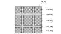
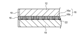
- FIG. 3 is a cross-sectional view taken along the line AA of the secondary battery shown in FIG. It is a figure which conceptually explains the shape change suppression of the negative electrode in the secondary battery which the ⁇ value is 30 or less by this invention. It is a figure which conceptually explains the shape change progress of the negative electrode in the secondary battery which the ⁇ value exceeds 30. It is sectional drawing which conceptually shows an example of the secondary battery according to this invention provided with a resin spacer. It is sectional drawing which conceptually shows an example of the secondary battery by this invention which provided with the negative electrode spacer. It is a figure which conceptually explains the shape change progress of the negative electrode in a conventional secondary battery.
- the secondary battery according to the present invention has a dissolution-precipitation type electrode in which the electrode active material is repeatedly dissolved and deposited as the electrode is charged and discharged.
- a typical example of the dissolution-precipitation type electrode is a zinc negative electrode used in a zinc secondary battery.
- the zinc secondary battery include a nickel zinc secondary battery, a silver zinc oxide secondary battery, a manganese zinc oxide secondary battery, and a zinc air secondary battery. Therefore, in the following description, the zinc secondary battery will be described as appropriate.
- FIGS 1 and 2 show a conceptual diagram of such a secondary battery.
- the secondary battery has a power generation unit 10.
- the power generation unit 10 includes a positive electrode layer 12, a negative electrode layer 14, a porous separator 16, and an electrolytic solution 18.
- the positive electrode layer 12 includes a positive electrode active material 12a and a positive electrode current collector 12b that supports the positive electrode active material 12a.
- the negative electrode layer 14 includes a negative electrode active material 14a and a negative electrode current collector 14b supporting the negative electrode active material 14a.
- the porous separator is interposed between the positive electrode layer 12 and the negative electrode layer 14.
- the positive electrode layer 12, the negative electrode layer 14, and the porous separator 16 are impregnated with the electrolytic solution 18.
- the negative electrode layer 14 is a dissolution-precipitation type electrode.
- the functional region 20 specified as the region where the positive electrode layer 12, the negative electrode layer 14, the electrolytic solution 18, and the porous separator 16 overlap is a plurality of power generation regions 20a.
- the power generation region 20a and the non-power generation region 20b are defined by the porous portion 16a and the dense portion 16b of the porous separator 16, respectively, but masking or a similar method (for example, a paste is applied to the porous portion 16a).
- the power generation region 20a and the non-power generation region 20b may be partitioned by other methods such as filling to obtain the non-power generation region 20b).
- the value ⁇ defined by the thickness (mm) of 16 is 30 or less.
- the negative electrode active material 14a By suppressing the shape change, the negative electrode active material 14a can be used efficiently. Therefore, the N / P ratio (the ratio of the capacity of the negative electrode active material to the capacity of the positive electrode active material) can be lowered, and as a result, a compact battery can be constructed.
- the negative electrode layer 14 shrinks unevenly from the end to the center as the negative electrode layer 14 repeats charging and discharging, that is, the outer peripheral portion of the negative electrode layer 14. Is unevenly eroded and lost. This is because the negative electrode active material 14a (for example, ZnO) constituting the negative electrode layer 14 moves from the end portion of the electrode toward the center through repeated dissolution and precipitation associated with charging and discharging. That is, the negative electrode layer 14 is gently deformed toward the center due to the diffusion of zinc oxide ions due to the dissolution of ZnO.
- the negative electrode active material 14a for example, ZnO
- a plurality of power generation regions 20a are partitioned by linear non-power generation regions 20b.
- the negative electrode active material 14a is repeatedly dissolved and deposited and deformed with charge and discharge, while the non-power generation region 20b is not or hardly involved in charge and discharge. Dissolution and precipitation of 14a are significantly suppressed.
- the negative electrode active material 14a which is deposited in each power generation region 20a due to charge / discharge and tends to cause a shape change, is dammed in the non-power generation region 20b.
- the shape change suppressing effect is inferior.
- the area circle equivalent diameter ⁇ per power generation region 20a is relatively wide, so that the left side ( ⁇ P) reflecting the shape changing force is reflected. ) Can be seen to overcome the right side (30 wt), which reflects the resistance to shape change.
- a large amount of the negative electrode active material 14a deposited due to charging / discharging in each power generation region 20a cannot be dammed in the non-power generation region 20b, and the negative electrode layer 14 cannot be dammed from the end to the inside. Allows the shape change to proceed.
- ⁇ is 30 or less, preferably 28 or less, more preferably 26 or less, and further preferably 24 or less.
- the lower limit of the value ⁇ is not particularly limited, but is typically 5 or more, and more typically 10 or more.
- the area circle equivalent diameter ⁇ per power generation region 20a is preferably 6.0 mm or less, more preferably 5.0 mm or less, further preferably 4.0 mm or less, particularly preferably 3.0 mm or less, and most preferably 2.0 mm. It is as follows.
- the area equivalent circle diameter is defined as the diameter of a circle having an area equal to the projected area per power generation area 20a, following the definition of JIS Z8827-1.
- the thickness P of the negative electrode layer 14 is preferably 0.1 to 1.0 mm, more preferably 0.2 to 0.9 mm, still more preferably 0.3 to 0.8 mm, and particularly preferably 0.4 to 0. It is 7 mm.
- the line width w of the non-power generation region 20b is preferably 0.01 to 1.0 mm, more preferably 0.1 to 0.9 mm, still more preferably 0.2 to 0.8 mm, and particularly preferably 0.3 to 0. It is 0.7 mm.
- the thickness t of the porous separator 16 is preferably 0.02 to 0.5 mm, more preferably 0.03 to 0.4 mm, still more preferably 0.04 to 0.3 mm, and particularly preferably 0.05 to 0. It is .2 mm.
- the thickness of the porous separator 16 may differ between the porous portion 16a and the dense portion 16b, but in that case, the thickness of the thicker portion (typically the porous portion 16a) is set to the thickness of the porous portion 16a. It may be adopted as a thickness t of 16.
- a spacer for example, a resin spacer or a negative electrode spacer
- a spacer 22 or 22' is provided between the negative electrode layer 14 and the dense portion 16b so as to fill the gap.
- the spacer 22 according to the preferred embodiment shown in FIG. 5 contains a resin. That is, by providing the resin spacer 22 at a position corresponding to the dense portion 16b, the gap between the negative electrode layer 14 and the dense portion 16b can be filled. By doing so, the diffusion of zincate ions can be suppressed more effectively as compared with the case where the spacer 22 is not provided, so that a more excellent shape change suppressing effect can be realized.
- the spacer 22' according to another preferred embodiment shown in FIG. 6 contains a negative electrode active material and / or a negative electrode current collector, thereby forming a convex portion 14c (hereinafter, also referred to as a negative electrode spacer 22') of the negative electrode layer 14. ing. That is, by forming the convex portion 14c containing the negative electrode active material and / or the negative electrode current collector at the position corresponding to the dense portion 16b on the surface of the negative electrode layer 14, the gap between the negative electrode layer 14 and the dense portion 16b is formed. Can be filled.
- the thickness t 1 (mm) of the convex portion 14c that is, the negative electrode spacer 22'
- the thickness t (mm) of the porous separator satisfy the relationship of t 1 / t ⁇ 0.5. It is preferable in that the diffusion of acid ions can be suppressed more effectively, and a more excellent shape change suppressing effect can be realized.
- the power generation area 20a and the non-power generation area 20b form a regular pattern.
- the power generation region 20a can be uniformly provided over the entire functional region 20, so that the shape change of the negative electrode can be suppressed more effectively.
- preferred regular patterns include, for example, the individual shapes of the power generation region 20a are squares, rectangles, rhombuses, triangles, other polygons, circles, etc., but are preferably squares or rhombuses.
- the porous separator 16 can be a separator generally used in various secondary batteries.
- Preferred porous separators 16 are porous membranes and / or non-woven fabrics. It is more preferable that the porous film and the non-woven fabric are made of resin in that a dense portion can be formed more efficiently than a hot press.
- the LDH separator for preventing zinc dendrite penetration in a zinc secondary battery as disclosed in Patent Documents 1 to 3 is a dense separator in which a porous substrate is filled with a layered double hydroxide (LDH). And therefore should be distinguished from porous separators.
- LDH layered double hydroxide
- the secondary battery is a zinc secondary battery
- the porous separator 16 is partitioned into a porous portion 16a and a dense portion 16b, the porous portion 16a defines a power generation region 20a, and the dense portion 16b defines a non-power generation region 20b. That is, it is preferable that the porous separator 16 is provided with the dense portion 16b, and the non-power generation region 20b is formed due to the denseness thereof. That is, since the function of the porous separator 16 is canceled by the denseness of the dense portion 16b, the dense portion 16b is not or hardly involved in charging / discharging, resulting in a non-power generation region 20b.
- the shape of the negative electrode can be changed only by using the porous separator 16 partitioned into the porous portion 16a and the dense portion 16b without separately requiring a special member for forming the non-power generation region 20b. Can be suppressed.
- the density of the dense portion 16b is 1.1 times or more, preferably 1.3 times or more, more preferably 1.5 times or more, still more preferably 1.8 times or more, and particularly preferably 1.8 times or more the density of the porous portion 16a. It is 2.0 times or more. The higher the density of the dense portion 16b, the better, so that the upper limit thereof is not particularly limited.
- the positive electrode layer 12 includes a positive electrode active material 12a and a positive electrode current collector 12b that supports the positive electrode active material 12a.
- a positive electrode active material 12a and the positive electrode current collector 12b appropriate materials may be selected according to the type of the secondary battery.
- the positive electrode active material 12a is preferably nickel hydroxide and / or nickel oxyhydroxide
- the positive electrode current collector 12b is preferably a nickel porous substrate such as a foamed nickel plate.
- the negative electrode layer 14 includes a negative electrode active material 14a and a negative electrode current collector 14b that supports the negative electrode active material 14a.
- the positive electrode active material 12a and the positive electrode current collector 12b appropriate materials may be selected according to the type of the secondary battery.
- the negative electrode active material 14a preferably contains a zinc material.
- the zinc material may be contained in any form of zinc metal, zinc compound and zinc alloy as long as it has an electrochemical activity suitable for the negative electrode.
- Preferred examples of the zinc material include zinc oxide, zinc metal, calcium zincate and the like, but a mixture of zinc metal and zinc oxide is more preferable.
- the electrolytic solution 18 may be an electrolytic solution 18 suitable for a secondary battery.
- the electrolytic solution 18 preferably contains an aqueous alkali metal hydroxide solution.
- the alkali metal hydroxide include potassium hydroxide, sodium hydroxide, lithium hydroxide, ammonium hydroxide and the like, but potassium hydroxide is more preferable.
- Zinc oxide, zinc hydroxide and the like may be added to the electrolytic solution in order to suppress autolysis of the zinc-containing material.
- the porous separator 16 is processed and partitioned into the porous portion 16a and the dense portion 16b, and (ii) the partitioned porous separator 16 and the positive electrode layer 12 are formed. This can be done by assembling a secondary battery using the negative electrode layer 14 and the electrolytic solution 18.
- Porous Separator 16 is processed to define a porous portion 16a that defines a plurality of power generation regions 20a and a linear non-power generation region 20b that defines each of the plurality of power generation regions 20a. It is partitioned into a dense portion 16b.
- the processing of the porous separator 16 is not particularly limited as long as the dense portion 16b has a predetermined density (for example, 1.1 times or more the porous portion 16a), but the porous separator 16 is air-pressed to be dense. It is preferable to form the portion 16b in terms of low cost and excellent mass productivity.
- the dense portion 16b can be easily and efficiently formed by pressing a predetermined patterned mold (projection) against the porous separator 16 and compressing it.
- the pattern of the mold (toppan) is preferably a regular pattern as described above. It is also preferable to heat the mold (toppan) when pressing it. By doing so, the density of the dense portion 16b can be further increased.
- the porous separator 16 is preferably made of resin.
- the secondary battery is assembled using the porous separator 16, the positive electrode layer 12, the negative electrode layer 14, and the electrolytic solution 18 partitioned as described above. This assembly may be performed according to a known method and is not particularly limited.
- the gap between the negative electrode layer 14 and the dense portion 16b can be filled on the surface of the negative electrode layer 14 and / or the surface of the dense portion 16b after the secondary battery is assembled.
- a spacer may be formed.
- the method for forming the spacer is not particularly limited, but when the resin spacer 22 as shown in FIG. 5 is formed, the resin paste is printed on the partitioned porous separator 16 obtained in the above step (i), or the above.
- the resin spacer 22 can be preferably formed by printing a resin paste on the negative electrode layer 14 or the like before the step (ii). Preferred examples of the printing method include screen printing, gravure printing and the like.
- the negative electrode spacer 22'as shown in FIG. 6 is formed, the negative electrode layer 14 is embossed or the like before the step (ii) to form irregularities on the surface thereof, thereby forming the negative electrode spacer 22. 'Can be preferably formed.
- the shape change of the negative electrode can be effectively suppressed only by subjecting the porous separator 16 to simple processing (for example, blank pressing), so that mass production or manufacturing can be performed. It can be said that it is extremely advantageous from the viewpoint of cost.
- Example 1 (comparison) (1) Preparation of Nickel-Zinc Secondary Battery A positive electrode layer, a negative electrode layer, a porous separator, and an electrolytic solution having the specifications shown below were prepared.
- -Positive electrode layer A positive electrode active material slurry containing nickel hydroxide particles filled in the pores of expanded nickel (positive electrode current collector) (size: 200 mm square, thickness: 0.5 mm).
- Negative electrode active material paste containing metallic zinc powder and zinc oxide powder is pressure-bonded to copper expanded metal (negative electrode current collector) (size: 200 mm square, thickness: 0.5 mm (thickness of negative electrode current collector) Including))
- -Porous separator Polypropylene non-woven fabric (thickness: 100 ⁇ m, basis weight: 40 g / m 2 )
- -Electrolyte 5.4 mol / L KOH aqueous solution in which 0.4 mol / L ZnO is dissolved
- the negative electrode layer was wrapped in a porous separator and housed in a battery container while facing the positive electrode layer.
- An electrolytic solution was injected into the battery container to obtain a nickel-zinc secondary battery.
- Examples 2-10 The porous separator was blank-pressed to form a dense portion so that a plurality of porous portions were partitioned into regular patterns of various shapes and dimensions shown in Table 1, and each of the porous separator and the negative electrode layer.
- a nickel-zinc secondary battery was prepared and evaluated in the same manner as in Example 1 except that the thickness was as shown in Table 1.
- a regular pattern pattern toppan is pressed against the porous separator before it is combined with the negative electrode layer, and the area to be a dense area (corresponding to the non-power generation area) is compressed while being heated. went.
- Examples 11-13 Nickel-zinc secondary batteries were prepared and evaluated in the same manner as in Examples 2 to 4, except that the resin spacers were formed and the thicknesses of the porous separator and the negative electrode layer were as shown in Table 2. rice field.
- the resin spacer was formed by screen-printing a resin paste on the surface of the dense portion of the porous separator.
- Examples 14-19 Except that the negative electrode spacer (convex portion of the negative electrode) was formed so as to have the t 1 / t ratio shown in Table 2, and the thicknesses of the porous separator and the negative electrode layer were set as shown in Table 2.
- Nickel-zinc secondary batteries were prepared and evaluated in the same manner as in Examples 2 to 4.
- the resin spacer is formed by embossing the surface of the negative electrode layer so that the gap between the negative electrode layer and the dense portion can be filled after assembly, and a predetermined t is formed on the portion facing the dense portion. This was done by forming a 1 / t ratio negative electrode convex portion.
- the functional area is divided into a plurality of power generation areas and a linear non-power generation area defining each of the plurality of power generation areas, and the value of the parameter ⁇ is 30.
- Examples 2, 4, 5 and 8 below compared with Example 1 having no non-power generation region and Examples 3, 6, 7, 9 and 10 having a non-power generation region but having an ⁇ value of more than 30.
- the residual area ratio of the negative electrode layer was high (that is, the negative electrode shape change was small), and the cycle life was long.
Landscapes
- Chemical & Material Sciences (AREA)
- Chemical Kinetics & Catalysis (AREA)
- Electrochemistry (AREA)
- General Chemical & Material Sciences (AREA)
- Engineering & Computer Science (AREA)
- Manufacturing & Machinery (AREA)
- Battery Electrode And Active Subsutance (AREA)
- Cell Separators (AREA)
Abstract
充放電の繰り返しに伴う負極のシェイプチェンジを低コストで効果的に抑制可能な二次電池が提供される。この二次電池は、正極層、負極層、多孔質セパレータ及び電解液を備えた発電単位を有し、負極層が溶解析出型電極であり、発電単位を平面視した場合に、正極層、負極層、電解液及び多孔質セパレータが重なる領域として特定される機能領域が、複数の発電領域と、複数の発電領域の各々を画定する線状の非発電領域とに区画化されており、発電領域は、式:α=ΦP/wt(式中、Φは発電領域1つ当たりの面積円相当径(mm)、Pは負極層の厚さ(mm)、wは非発電領域の線幅(mm)、tは多孔質セパレータの厚さ(mm)である)により定義される値αが30以下である。
Description
本発明は、二次電池、特に充放電に伴い電極活物質の溶解及び析出が繰り返される溶解析出型電極を有する二次電池、及びその製造方法に関するものである。
亜鉛二次電池等の、充放電に伴い電極活物質の溶解及び析出が繰り返される溶解析出型電極を有する二次電池において、充放電の繰り返しに伴い負極形状が望ましくない形状及びサイズに変化していく、負極シェイプチェンジの問題が知られている。例えば、亜鉛二次電池の場合、図7に示されるように、負極層14が充放電を繰り返すにつれて端部から中央に向かって不均一に縮小していく、すなわち負極層14の外周部分が不均一に浸食されて失われていく現象が見られる。これは負極層14を構成する負極活物質14a(ZnO)が充放電に伴う溶解及び析出の繰り返しを経て、電池の端部から中心方向に移動することによるものである。つまり、ZnOの溶解による亜鉛酸イオンの拡散によって、負極層14がなだらかに中心に向かって変形していく。かかる負極層14のシェイプチェンジは、正極層12と対向する負極層14の有効領域の減少につながり、その結果、電池抵抗の上昇や電池容量の低下、ひいては二次電池の短寿命化を招く。
このような負極シェイプチェンジの問題に対処すべく、様々な亜鉛二次電池が提案されている。例えば、特許文献1(特開2019-106351号公報)には、正極活物質層の端部における電気化学反応を抑制する正極反応抑制構造、及び/又は負極活物質層の余剰外周領域における電気化学反応を抑制する負極反応抑制構造を有する亜鉛二次電池が開示されている。特許文献2(特開2020-38763号公報)には、負極にAl、In、Ti及びNbからなる群から選択される少なくとも1種とZnとの複合金属酸化物であるZn化合物を含有させた亜鉛二次電池が開示されている。特許文献3(WO2020/049902)には、(A)ZnO粒子と、(B)(i)平均粒径D50が5~80μmである金属Zn粒子、(ii)In及びBiから選択される1種以上の金属元素、並びに(iii)ヒドロキシル基を有するバインダー樹脂から選択される少なくとも2つとを含む負極を備えた、亜鉛二次電池が開示されている。
特許文献1の手法では、正極及び/又は負極に反応抑制構造を別途設ける必要があるため、製造工程が複雑化し、製造コストも増大する。また、特許文献2の手法では負極に追加成分を加える必要があるため、やはり製造コストが増大する。したがって、既存の正極、負極及びセパレータを用いて、簡単な加工を施すのみで、負極のシェイプチェンジを抑制できれば、量産化や製造コストの観点から有利といえる。
本発明者らは、今般、所定の条件を満たすように線状の非発電領域で複数の発電領域を区画化するだけで、負極のシェイプチェンジを低コストで効果的に抑制できるとの知見を得た。
したがって、本発明の目的は、充放電の繰り返しに伴う負極のシェイプチェンジを低コストで効果的に抑制可能な二次電池を提供することにある。
本発明の一態様によれば、充放電に伴い電極活物質の溶解及び析出が繰り返される溶解析出型電極を有する二次電池であって、前記二次電池が発電単位を有し、
前記発電単位が、
正極活物質及びそれを支持する正極集電体を含む正極層と、
負極活物質及びそれを支持する負極集電体を含む負極層と、
前記正極層及び前記負極層の間に介在する多孔質セパレータと、
前記正極層、前記負極層及び前記多孔質セパレータが含浸される電解液と、
を備え、前記負極層が前記溶解析出型電極であり、
前記発電単位を平面視した場合に、前記正極層、前記負極層、前記電解液及び前記多孔質セパレータが重なる領域として特定される機能領域が、複数の発電領域と、前記複数の発電領域の各々を画定する線状の非発電領域とに区画化されており、
前記発電領域は、下記式:
α=ΦP/wt
(式中、Φは前記発電領域1つ当たりの面積円相当径(mm)、Pは前記負極層の厚さ(mm)、wは前記非発電領域の線幅(mm)、tは前記多孔質セパレータの厚さ(mm)である)により定義される値αが30以下である、二次電池が提供される。
本発明の他の一態様によれば、前記二次電池の製造方法であって、
多孔質セパレータを加工して、複数の発電領域を規定する多孔部と、前記複数の発電領域の各々を画定する線状の非発電領域を規定する緻密部とに区画化する工程と、
前記区画された多孔質セパレータ、前記正極層、前記負極層及び前記電解液を用いて前記二次電池を組み立てる工程と、
を含む、二次電池の製造方法が提供される。
多孔質セパレータを加工して、複数の発電領域を規定する多孔部と、前記複数の発電領域の各々を画定する線状の非発電領域を規定する緻密部とに区画化する工程と、
前記区画された多孔質セパレータ、前記正極層、前記負極層及び前記電解液を用いて前記二次電池を組み立てる工程と、
を含む、二次電池の製造方法が提供される。
二次電池
本発明による二次電池は、充放電に伴い電極活物質の溶解及び析出が繰り返される溶解析出型電極を有するものである。溶解析出型電極の典型例としては、亜鉛二次電池に用いられる亜鉛負極が挙げられる。亜鉛二次電池の例としては、ニッケル亜鉛二次電池、酸化銀亜鉛二次電池、酸化マンガン亜鉛二次電池、亜鉛空気二次電池が挙げられる。したがって、以下の説明においては、亜鉛二次電池に関する説明を適宜行うものとする。
本発明による二次電池は、充放電に伴い電極活物質の溶解及び析出が繰り返される溶解析出型電極を有するものである。溶解析出型電極の典型例としては、亜鉛二次電池に用いられる亜鉛負極が挙げられる。亜鉛二次電池の例としては、ニッケル亜鉛二次電池、酸化銀亜鉛二次電池、酸化マンガン亜鉛二次電池、亜鉛空気二次電池が挙げられる。したがって、以下の説明においては、亜鉛二次電池に関する説明を適宜行うものとする。
図1及び2にそのような二次電池の概念図を示す。二次電池は発電単位10を有する。発電単位10は、正極層12と、負極層14と、多孔質セパレータ16と、電解液18とを備える。正極層12は、正極活物質12a及びそれを支持する正極集電体12bを含む。負極層14は、負極活物質14a及びそれを支持する負極集電体14bを含む。多孔質セパレータは、正極層12及び負極層14の間に介在される。正極層12、負極層14及び多孔質セパレータ16は電解液18で含浸される。負極層14は溶解析出型電極である。この二次電池は、発電単位10を平面視した場合に、正極層12、負極層14、電解液18及び多孔質セパレータ16が重なる領域として特定される機能領域20が、複数の発電領域20aと、複数の発電領域20aの各々を画定する線状の非発電領域20bとに区画化されている。図1及び2では、発電領域20a及び非発電領域20bは、多孔質セパレータ16の多孔部16a及び緻密部16bによってそれぞれ規定されているが、マスキング、あるいはそれに類する手法(例えば多孔部16aにペーストを充填して非発電領域20bとする)等の他の手法によって発電領域20a及び非発電領域20bを区画化してもよい。
そして、発電領域20aは、下記式:
α=ΦP/wt
(式中、Φは発電領域20a1つ当たりの面積円相当径(mm)、Pは負極層14の厚さ(mm)、wは非発電領域20bの線幅(mm)、tは多孔質セパレータ16の厚さ(mm)である)により定義される値αが30以下である。このように、溶解析出型電極を有する二次電池において、所定の条件を満たすように線状の非発電領域20bで複数の発電領域20aを区画化するだけで、負極のシェイプチェンジを低コストで効果的に抑制することができる。シェイプチェンジを抑制することで、負極活物質14aを効率的に使用することができる。したがって、N/P比(正極活物質の容量に対する負極活物質の容量の比)を下げることができ、その結果、コンパクトな電池を構成することができる。
αが30以下であると負極のシェイプチェンジが抑制される推定メカニズムについて、図3~5を参照しながら以下に説明する。従来の亜鉛二次電池においては、図7に基づいて前述したように、負極層14が充放電を繰り返すにつれて端部から中央に向かって不均一に縮小していく、すなわち負極層14の外周部分が不均一に浸食されて失われていく現象が見られる。これは負極層14を構成する負極活物質14a(例えばZnO)が充放電に伴う溶解及び析出の繰り返しを経て、電極の端部から中心方向に移動することによるものである。つまり、ZnOの溶解による亜鉛酸イオンの拡散によって、負極層14がなだらかに中心に向かって変形していく。これに対し、本発明の二次電池においては、図3に示されるように、複数の発電領域20aが線状の非発電領域20bで区画化されている。その結果、発電領域20aでは充放電に伴い負極活物質14aが溶解及び析出を繰り返して変形していく一方、非発電領域20bは充放電に全く又は殆ど関与しないため、充放電に伴う負極活物質14aの溶解及び析出が有意に抑えられる。その結果、個々の発電領域20aにおいて充放電に伴い析出してシェイプチェンジを起こそうとする負極活物質14aが非発電領域20bでせき止められる形になるものと考えられる。これは、発電領域20a(具体的にはそこに変形を伴いながら析出していく負極活物質14a)がもたらすシェイプチェンジする力に、非発電領域20bがもたらすシェイプチェンジに対する抗力が打ち勝つことにより実現されるものと考えられる。発電領域20aがもたらすシェイプチェンジする力に寄与するファクターとしては、発電領域20a1つ当たりの面積円相当径Φ、及び負極層14の厚さPが挙げられる。これらは発電領域20aにおける充放電に関与する有効な負極活物質14aの量を左右するからである。一方、非発電領域20bがもたらすシェイプチェンジに対する抗力に寄与するファクターとしては、非発電領域20bの線幅w、及び多孔質セパレータ16の厚さtが挙げられる。つまり、α=(ΦP/wt)が30以下であることは、ΦP/wt≦30、さらにはΦP≦30wtと表現できるところ、この不等式はシェイプチェンジする力を反映する左辺(ΦP)に、シェイプチェンジに対する抗力を反映する右辺(30wt)が打ち勝つこと、すなわちシェイプチェンジを抑制することにつながるといえる。
これに対し、αが30を超える場合(すなわちΦP>30wt)には、シェイプチェンジ抑制効果が劣るものとなる。例えば、図4に示されるように、非発電領域20bが相対的に広い場合、発電領域20a1つ当たりの面積円相当径Φが相対的に広くなるため、シェイプチェンジする力を反映する左辺(ΦP)が、シェイプチェンジに対する抗力を反映する右辺(30wt)に打ち勝ってしまうとみることができる。その結果、図4に示されるように、個々の発電領域20aにおいて充放電に伴い析出した多量の負極活物質14aを非発電領域20bでせき止めることができなくなり、負極層14の端部から内部に向かうシェイプチェンジの進行を許してしまう。これは、正極層12と多孔質セパレータ16との間に隙間Gが発生し、そこに電解液18が流入してシェイプチェンジを加速させるものと推察される。この点、αを30以下とすることで上記問題を回避することができ、その結果、負極のシェイプチェンジ抑制を効果的に実現することができる。この場合、図4に示されるように、発電領域20a1つ当たりの負極活物質14a量が相対的に少なく、それ故、非発電領域20bがせきとめる効果を十分に奏することができるといえる。
上記効果の観点から、αは30以下であり、好ましくは28以下、より好ましくは26以下、さらに好ましくは24以下である。値αの下限値は特に限定されないが、典型的には、5以上、より典型的には10以上である。
発電領域20a1つ当たりの面積円相当径Φは、6.0mm以下が好ましく、より好ましくは5.0mm以下、さらに好ましくは4.0mm以下、特に好ましくは3.0mm以下、最も好ましくは2.0mm以下である。面積円相当径は、JIS Z8827-1の定義に倣って、発電領域20a1つ当たりの投影面積と等しい面積を持つ円の直径として定義される。負極層14の厚さPは、0.1~1.0mmが好ましく、より好ましくは0.2~0.9mm、さらに好ましくは0.3~0.8mm、特に好ましくは0.4~0.7mmである。非発電領域20bの線幅wは、0.01~1.0mmが好ましく、より好ましくは0.1~0.9mm、さらに好ましくは0.2~0.8mm、特に好ましくは0.3~0.7mmである。多孔質セパレータ16の厚さtは、0.02~0.5mmが好ましく、より好ましくは0.03~0.4mm、さらに好ましくは0.04~0.3mm、特に好ましくは0.05~0.2mmである。なお、多孔質セパレータ16の厚さは、多孔部16aと緻密部16bとで異なる場合がありうるが、その場合、厚い方の部分(典型的には多孔部16a)の厚さを多孔質セパレータ16の厚さtとして採用すればよい。
もっとも、多孔部16aに対して緻密部16bが薄い場合、薄い緻密部16bにスペーサ(例えば樹脂スペーサや負極スペーサ)を配置して多孔部16aの厚さと同じになるように、すなわち多孔質セパレータ16が全体にわたって均一の厚さになるようにしてもよい。すなわち、図5及び6に示されるように、負極層14と緻密部16bとの間に、その隙間を埋めるようにスペーサ22又は22’が設けられているのが好ましい。
図5に示される好ましい態様によるスペーサ22は樹脂を含む。すなわち、樹脂スペーサ22を緻密部16bに対応する位置に設けることで、負極層14と緻密部16bとの間の隙間を埋めることができる。こうすることで、スペーサ22が無い場合と比較して、亜鉛酸イオンの拡散をより効果的に抑えることができるため、さらに優れたシェイプチェンジ抑制効果を実現することができる。
図6に示される別の好ましい態様によるスペーサ22’は、負極活物質及び/又は負極集電体を含み、それにより負極層14の凸部14c(以下、負極スペーサ22’ともいう)を成している。すなわち、負極層14の表面の緻密部16bに対応する位置に、負極活物質及び/又は負極集電体を含む凸部14cを形成することで、負極層14と緻密部16bとの間の隙間を埋めることができる。この場合、この凸部14c(すなわち負極スペーサ22’)の厚さt1(mm)及び多孔質セパレータの厚さt(mm)はt1/t≦0.5の関係を満たすのが、亜鉛酸イオンの拡散をより効果的に抑えることができ、それによりさらに優れたシェイプチェンジ抑制効果を実現できる点で好ましい。
発電領域20a及び非発電領域20bは規則的なパターンを成しているのが好ましい。規則的なパターンとすることで、発電領域20aを機能領域20のぜんいきにわたって均一に設けることができるので、負極のシェイプチェンジをより効果的に抑制できる。好ましい規則的なパターンの例としては、発電領域20aの個々の形状が、正方形、長方形、菱形、三角形、その他の多角形、円形等が挙げられるが、好ましくは正方形又は菱形である。
多孔質セパレータ16は、各種二次電池において一般的に使用されるセパレータであることができる。好ましい多孔質セパレータ16は、多孔質膜及び/又は不織布である。多孔質膜及び不織布は樹脂製であるのが、熱プレスより緻密部を効率的に形成できる点でより好ましい。なお、特許文献1~3に開示されるような、亜鉛二次電池における亜鉛デンドライト貫通阻止のためのLDHセパレータは、多孔質基材が層状複水酸化物(LDH)で充填された緻密なセパレータであり、それ故、多孔質セパレータとは区別されるべきものである。もっとも、二次電池が亜鉛二次電池の場合、LDHセパレータを併用することが望ましく、その場合は、正極層12/LDHセパレータ/多孔質セパレータ16/負極層14の順に配置されるのが好ましい。
好ましくは、多孔質セパレータ16は、多孔部16a及び緻密部16bに区画化されており、多孔部16aが発電領域20aを規定し、緻密部16bが非発電領域20bを規定する。つまり、多孔質セパレータ16に緻密部16bを設け、その緻密性により非発電領域20bを形成するのが好ましい。すなわち、緻密部16bはその緻密性により多孔質セパレータ16の機能が打ち消されるため、充放電に全く又は殆ど関与しないこととなり、結果として非発電領域20bをもたらすこととなる。この態様によれば、非発電領域20bを形成するための特別な部材を別途必要とすることなく、多孔部16a及び緻密部16bに区画化された多孔質セパレータ16を用いるだけで負極のシェイプチェンジを抑制できる。これは、低コストでシェイプチェンジ抑制効果を得られることのみならず、部材点数の増加やそれに伴う体積の増加による電池のエネルギー密度の低下を回避できる点でも有利といえる。緻密部16bの密度は、多孔部16aの密度の1.1倍以上であり、好ましくは1.3倍以上、より好ましくは1.5倍以上、さらに好ましくは1.8倍以上、特に好ましくは2.0倍以上である。緻密部16bの密度は高ければ高いほど良いため、その上限は特に限定されない。
正極層12は、正極活物質12a及びそれを支持する正極集電体12bを含む。正極活物質12a及び正極集電体12bは二次電池の種類に応じた適切な材料をそれぞれ選択すればよい。例えば、ニッケル亜鉛二次電池の場合、正極活物質12aは水酸化ニッケル及び/又はオキシ水酸化ニッケルであるのが好ましく、正極集電体12bは発泡ニッケル板等のニッケル製多孔質基板が好ましい。
負極層14は、負極活物質14a及びそれを支持する負極集電体14bを含む。正極活物質12a及び正極集電体12bは二次電池の種類に応じた適切な材料をそれぞれ選択すればよい。亜鉛二次電池の場合、負極活物質14aは亜鉛材料を含むのが好ましい。亜鉛材料は、負極に適した電気化学的活性を有するものであれば、亜鉛金属、亜鉛化合物及び亜鉛合金のいずれの形態で含まれていてもよい。亜鉛材料の好ましい例としては、酸化亜鉛、亜鉛金属、亜鉛酸カルシウム等が挙げられるが、亜鉛金属及び酸化亜鉛の混合物がより好ましい。
電解液18は、二次電池に適したものを用いればよい。亜鉛二次電池の場合、電解液18は、アルカリ金属水酸化物水溶液を含むのが好ましい。アルカリ金属水酸化物の例としては、水酸化カリウム、水酸化ナトリウム、水酸化リチウム、水酸化アンモニウム等が挙げられるが、水酸化カリウムがより好ましい。亜鉛含有材料の自己溶解を抑制するために、電解液中に酸化亜鉛、水酸化亜鉛等を添加してもよい。
二次電池の製造方法
本発明による二次電池は、(i)多孔質セパレータ16を加工して多孔部16a及び緻密部16bに区画化し、(ii)区画された多孔質セパレータ16、正極層12、負極層14及び電解液18を用いて二次電池を組み立てることにより行うことができる。
本発明による二次電池は、(i)多孔質セパレータ16を加工して多孔部16a及び緻密部16bに区画化し、(ii)区画された多孔質セパレータ16、正極層12、負極層14及び電解液18を用いて二次電池を組み立てることにより行うことができる。
(i)多孔質セパレータの加工
多孔質セパレータ16を加工して、複数の発電領域20aを規定する多孔部16aと、複数の発電領域20aの各々を画定する線状の非発電領域20bを規定する緻密部16bとに区画化する。この多孔質セパレータ16の加工は、緻密部16bを所定の密度(例えば多孔部16aの1.1倍以上)にするものであれば特に限定されないが、多孔質セパレータ16を空押し加工して緻密部16bを形成させることにより行われるのが低コストでかつ量産性に優れる点で好ましい。空押し加工によれば、多孔質セパレータ16に所定のパターン状の型(凸版)を押し当てて圧縮することにより緻密部16bを簡便かつ効率的に形成できる。型(凸版)のパターンは、前述したような規則的なパターンであるのが好ましい。また、型(凸版)を押し当てる際、加熱を行うのも好ましい。こうすることで緻密部16bの密度を更に高めることができる。この目的のためには、多孔質セパレータ16は樹脂製であるのが好ましい。
多孔質セパレータ16を加工して、複数の発電領域20aを規定する多孔部16aと、複数の発電領域20aの各々を画定する線状の非発電領域20bを規定する緻密部16bとに区画化する。この多孔質セパレータ16の加工は、緻密部16bを所定の密度(例えば多孔部16aの1.1倍以上)にするものであれば特に限定されないが、多孔質セパレータ16を空押し加工して緻密部16bを形成させることにより行われるのが低コストでかつ量産性に優れる点で好ましい。空押し加工によれば、多孔質セパレータ16に所定のパターン状の型(凸版)を押し当てて圧縮することにより緻密部16bを簡便かつ効率的に形成できる。型(凸版)のパターンは、前述したような規則的なパターンであるのが好ましい。また、型(凸版)を押し当てる際、加熱を行うのも好ましい。こうすることで緻密部16bの密度を更に高めることができる。この目的のためには、多孔質セパレータ16は樹脂製であるのが好ましい。
(ii)二次電池の組み立て
上記のようにして区画された多孔質セパレータ16、正極層12、負極層14及び電解液18を用いて二次電池を組み立てる。この組み立ては、公知の手法に従って行えばよく特に限定されない。
上記のようにして区画された多孔質セパレータ16、正極層12、負極層14及び電解液18を用いて二次電池を組み立てる。この組み立ては、公知の手法に従って行えばよく特に限定されない。
(iii)スペーサの形成
前述したように、負極層14の表面及び/又は緻密部16bの表面に、二次電池の組み立て後に負極層14と緻密部16bとの間の隙間を埋めることができるように、スペーサを形成してもよい。スペーサの形成方法は特に限定されないが、図5に示されるような樹脂スペーサ22を形成する場合、上記工程(i)で得られた区画された多孔質セパレータ16に樹脂ペーストを印刷する、あるいは上記工程(ii)の前に負極層14に樹脂ペーストを印刷すること等により、樹脂スペーサ22を好ましく形成することができる。印刷法の好ましい例としては、スクリーン印刷、グラビア印刷等が挙げられる。また、図6に示されるような負極スペーサ22’を形成する場合、上記工程(ii)の前に負極層14にエンボス加工等を施すことでその表面に凹凸を形成することにより、負極スペーサ22’を好ましく形成することができる。
前述したように、負極層14の表面及び/又は緻密部16bの表面に、二次電池の組み立て後に負極層14と緻密部16bとの間の隙間を埋めることができるように、スペーサを形成してもよい。スペーサの形成方法は特に限定されないが、図5に示されるような樹脂スペーサ22を形成する場合、上記工程(i)で得られた区画された多孔質セパレータ16に樹脂ペーストを印刷する、あるいは上記工程(ii)の前に負極層14に樹脂ペーストを印刷すること等により、樹脂スペーサ22を好ましく形成することができる。印刷法の好ましい例としては、スクリーン印刷、グラビア印刷等が挙げられる。また、図6に示されるような負極スペーサ22’を形成する場合、上記工程(ii)の前に負極層14にエンボス加工等を施すことでその表面に凹凸を形成することにより、負極スペーサ22’を好ましく形成することができる。
このように本発明の製造方法によれば、多孔質セパレータ16に簡単な加工(例えば空押し加工)を施すだけで、負極のシェイプチェンジを効果的に抑制することができるため、量産化や製造コストの観点から極めて有利といえる。
本発明を以下の例によってさらに具体的に説明する。
例1(比較)
(1)ニッケル亜鉛二次電池の作製
以下に示される仕様の、正極層、負極層、多孔質セパレータ及び電解液を用意した。
‐正極層:水酸化ニッケル粒子を含む正極活物質スラリーを発泡ニッケル(正極集電体)の気孔内に充填させたもの(サイズ:200mm角、厚さ:0.5mm)
‐負極層:金属亜鉛粉末及び酸化亜鉛粉末を含む負極活物質ペーストを銅エキスパンドメタル(負極集電体)に圧着したもの(サイズ:200mm角、厚さ:0.5mm(負極集電体の厚さを含む))
‐多孔質セパレータ:ポリプロピレン製不織布(厚さ:100μm、目付:40g/m2)
‐電解液:0.4mol/LのZnOを溶解させた5.4mol/LのKOH水溶液
負極層を多孔質セパレータで包み込み、正極層と対向させつつ、電池容器に収容した。電池容器内に電解液を注入して、ニッケル亜鉛二次電池とした。
(2)充放電サイクル試験
得られたニッケル亜鉛二次電池に対して充放電サイクル試験を行った。この試験は、以下の条件:
‐充電:電圧:1.9V、終止容量:70%
‐放電:終止容量:0%
の充放電サイクルを100回繰り返すことにより行った。サイクル試験前後における負極層を平面視して、サイクル試験開始前に負極活物質で覆われていた面積S0に対する、100サイクル試験終了時に残存していた負極活物質で覆われる面積S1の割合(%)(すなわち100×S1/S0)を算出して、負極層の残存面積率(%)を得た。得られた負極層の残存面積率(%)を以下の基準に当てはめることにより、シェイプチェンジ抑制効果を3段階で格付け評価した。
‐評価A:負極層の残存面積率が70%以上
‐評価B:負極層の残存面積率が60%以上70%未満
‐評価C:負極層の残存面積率が60%未満
例2~10
多孔質セパレータを空押し加工して表1に示される各種形状及び寸法の規則的パターンに複数の多孔部が区画化されるように緻密部を形成したこと、並びに多孔質セパレータ及び負極層の各厚さを表1に示されるとおりとしたこと以外は、例1と同様にしてニッケル亜鉛二次電池の作製及び評価を行った。空押し加工は、負極層と組み合わせる前の多孔質セパレータに規則的パターン状の型(凸版)を押し当てて、緻密部(非発電領域に対応)とすべき領域を加熱しながら圧縮することにより行った。
多孔質セパレータを空押し加工して表1に示される各種形状及び寸法の規則的パターンに複数の多孔部が区画化されるように緻密部を形成したこと、並びに多孔質セパレータ及び負極層の各厚さを表1に示されるとおりとしたこと以外は、例1と同様にしてニッケル亜鉛二次電池の作製及び評価を行った。空押し加工は、負極層と組み合わせる前の多孔質セパレータに規則的パターン状の型(凸版)を押し当てて、緻密部(非発電領域に対応)とすべき領域を加熱しながら圧縮することにより行った。
例11~13
樹脂スペーサを形成したこと、並びに多孔質セパレータ及び負極層の各厚さを表2に示されるとおりとしたこと以外は、例2~4と同様にしてニッケル亜鉛二次電池の作製及び評価を行った。樹脂スペーサの形成は、多孔質セパレータの緻密部の表面に樹脂ペーストをスクリーン印刷することにより行った。
樹脂スペーサを形成したこと、並びに多孔質セパレータ及び負極層の各厚さを表2に示されるとおりとしたこと以外は、例2~4と同様にしてニッケル亜鉛二次電池の作製及び評価を行った。樹脂スペーサの形成は、多孔質セパレータの緻密部の表面に樹脂ペーストをスクリーン印刷することにより行った。
例14~19
負極スペーサ(負極凸部)を表2に示されるt1/t比となるように形成したこと、並びに多孔質セパレータ及び負極層の各厚さを表2に示されるとおりとしたこと以外は、例2~4と同様にしてニッケル亜鉛二次電池の作製及び評価を行った。樹脂スペーサの形成は、組み立て後に負極層と緻密部との間の隙間を埋めることができるように、負極層の表面にエンボス加工を施して、緻密部と対向することになる部分に所定のt1/t比の負極凸部を形成することにより行った。
負極スペーサ(負極凸部)を表2に示されるt1/t比となるように形成したこと、並びに多孔質セパレータ及び負極層の各厚さを表2に示されるとおりとしたこと以外は、例2~4と同様にしてニッケル亜鉛二次電池の作製及び評価を行った。樹脂スペーサの形成は、組み立て後に負極層と緻密部との間の隙間を埋めることができるように、負極層の表面にエンボス加工を施して、緻密部と対向することになる部分に所定のt1/t比の負極凸部を形成することにより行った。
結果
例1~19で作製した電池の仕様及びサイクル試験の結果を以下の表に示す。
例1~19で作製した電池の仕様及びサイクル試験の結果を以下の表に示す。

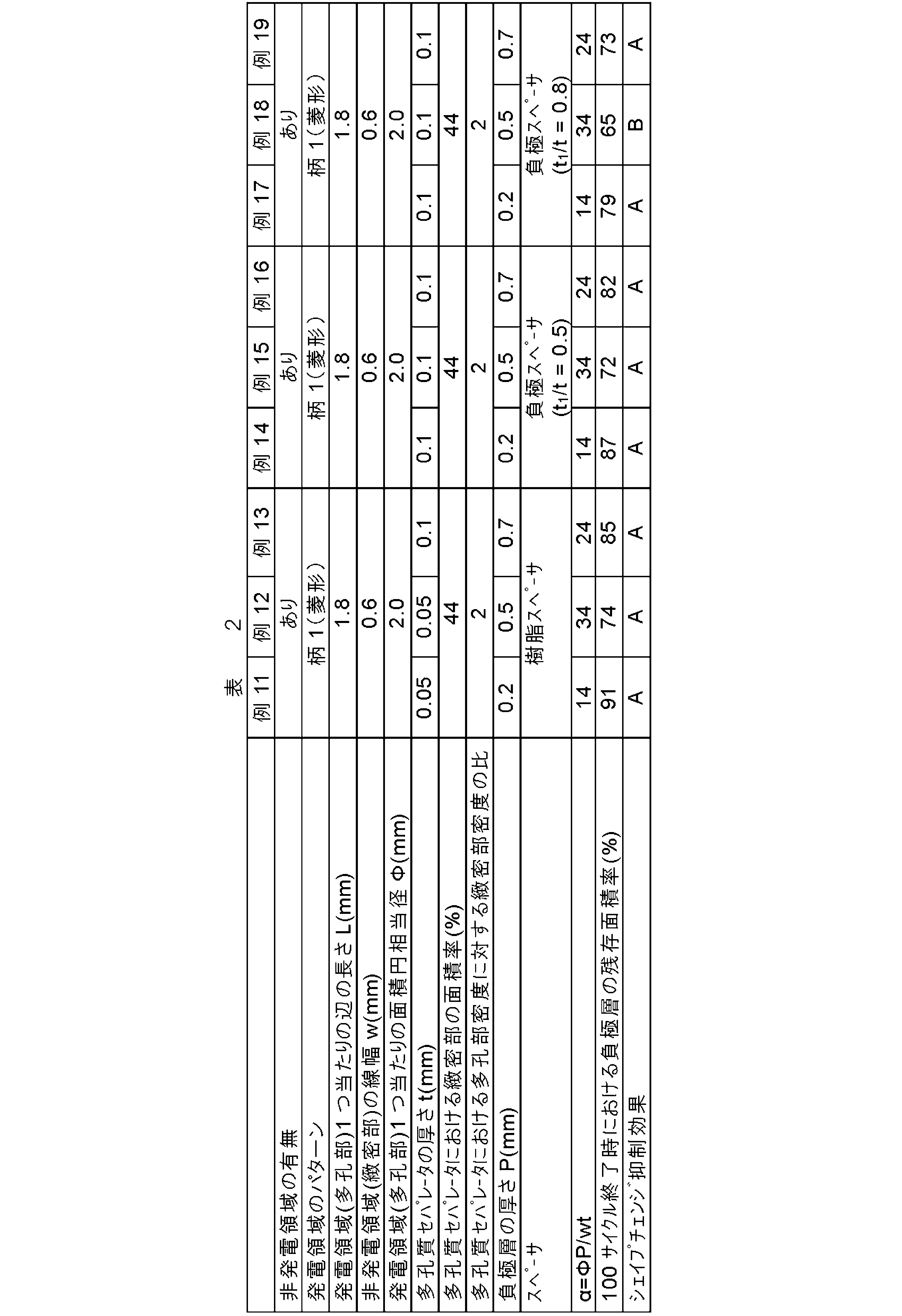
表1に示される結果から分かるように、機能領域が、複数の発電領域と、複数の発電領域の各々を画定する線状の非発電領域とに区画化され、かつ、パラメータαの値が30以下である例2、4、5及び8においては、非発電領域を有しない例1、非発電領域を有するがαの値が30を超える例3、6、7、9及び10と比較して、100サイクル終了時における負極層の残存面積率が高く(すなわち負極シェイプチェンジが小さく)、サイクル寿命が長くなった。
Claims (15)
- 充放電に伴い電極活物質の溶解及び析出が繰り返される溶解析出型電極を有する二次電池であって、前記二次電池が発電単位を有し、
前記発電単位が、
正極活物質及びそれを支持する正極集電体を含む正極層と、
負極活物質及びそれを支持する負極集電体を含む負極層と、
前記正極層及び前記負極層の間に介在する多孔質セパレータと、
前記正極層、前記負極層及び前記多孔質セパレータが含浸される電解液と、
を備え、前記負極層が前記溶解析出型電極であり、
前記発電単位を平面視した場合に、前記正極層、前記負極層、前記電解液及び前記多孔質セパレータが重なる領域として特定される機能領域が、複数の発電領域と、前記複数の発電領域の各々を画定する線状の非発電領域とに区画化されており、
前記発電領域は、下記式:
α=ΦP/wt
(式中、Φは前記発電領域1つ当たりの面積円相当径(mm)、Pは前記負極層の厚さ(mm)、wは前記非発電領域の線幅(mm)、tは前記多孔質セパレータの厚さ(mm)である)により定義される値αが30以下である、二次電池。 - 前記値αが24以下である、請求項1に記載の二次電池。
- 前記多孔質セパレータが、多孔部と、前記多孔部の1.1倍以上の密度を有する緻密部とに区画化されており、前記多孔部が前記発電領域を規定し、前記緻密部が前記非発電領域を規定する、請求項1又は2に記載の二次電池。
- 前記発電領域及び前記非発電領域が規則的なパターンを成している、請求項1~3のいずれか一項に記載の二次電池。
- 前記発電領域1つ当たりの面積円相当径が、3.0mm以下である、請求項1~4のいずれか一項に記載の二次電池。
- 前記非発電領域の線幅wが0.01~1.0mmである、請求項1~5のいずれか一項に記載の二次電池。
- 前記セパレータが、多孔質膜及び/又は不織布である、請求項1~6のいずれか一項に記載の二次電池。
- 前記負極活物質が亜鉛材料を含む、請求項1~7のいずれか一項に記載の二次電池。
- 前記負極層と前記緻密部との間に、その隙間を埋めるようにスペーサが設けられている、請求項3に記載の二次電池。
- 前記スペーサが樹脂を含む、請求項9に記載の二次電池。
- 前記スペーサが、前記負極活物質及び/又は前記負極集電体を含み、それにより前記負極層の凸部を成している、請求項9に記載の二次電池。
- 前記凸部の厚さt1(mm)及び前記多孔質セパレータの厚さt(mm)が、下記式:
t1/t≦0.5
を満たす、請求項11に記載の二次電池。 - 請求項1~12のいずれか一項に記載の二次電池の製造方法であって、
多孔質セパレータを加工して、複数の発電領域を規定する多孔部と、前記複数の発電領域の各々を画定する線状の非発電領域を規定する緻密部とに区画化する工程と、
前記区画された多孔質セパレータ、前記正極層、前記負極層及び前記電解液を用いて前記二次電池を組み立てる工程と、
を含む、二次電池の製造方法。 - 前記多孔質セパレータの加工が、前記多孔質セパレータを空押し加工して前記緻密部を形成させることにより行われる、請求項13に記載の二次電池の製造方法。
- 前記負極層の表面及び/又は前記緻密部の表面に、前記二次電池の組み立て後に前記負極層と前記緻密部との間の隙間を埋めることができるように、スペーサを形成する工程をさらに含む、請求項13又は14に記載の二次電池の製造方法。
Priority Applications (2)
| Application Number | Priority Date | Filing Date | Title |
|---|---|---|---|
| JP2022546976A JPWO2022050367A1 (ja) | 2020-09-04 | 2021-09-02 | |
| US18/161,933 US20230170534A1 (en) | 2020-09-04 | 2023-01-31 | Secondary battery and manufacturing method therefor |
Applications Claiming Priority (2)
| Application Number | Priority Date | Filing Date | Title |
|---|---|---|---|
| JP2020-149465 | 2020-09-04 | ||
| JP2020149465 | 2020-09-04 |
Related Child Applications (1)
| Application Number | Title | Priority Date | Filing Date |
|---|---|---|---|
| US18/161,933 Continuation US20230170534A1 (en) | 2020-09-04 | 2023-01-31 | Secondary battery and manufacturing method therefor |
Publications (1)
| Publication Number | Publication Date |
|---|---|
| WO2022050367A1 true WO2022050367A1 (ja) | 2022-03-10 |
Family
ID=80491071
Family Applications (1)
| Application Number | Title | Priority Date | Filing Date |
|---|---|---|---|
| PCT/JP2021/032373 Ceased WO2022050367A1 (ja) | 2020-09-04 | 2021-09-02 | 二次電池及びその製造方法 |
Country Status (3)
| Country | Link |
|---|---|
| US (1) | US20230170534A1 (ja) |
| JP (1) | JPWO2022050367A1 (ja) |
| WO (1) | WO2022050367A1 (ja) |
Citations (4)
| Publication number | Priority date | Publication date | Assignee | Title |
|---|---|---|---|---|
| JPH04206468A (ja) * | 1990-11-30 | 1992-07-28 | Yuasa Corp | 密閉型アルカリ亜鉛蓄電池 |
| JP2004146238A (ja) * | 2002-10-25 | 2004-05-20 | Matsushita Electric Ind Co Ltd | 電池用セパレータ及び電池 |
| JP2009516325A (ja) * | 2005-09-16 | 2009-04-16 | スプ カン,ボン | 区画された電解質を有するリチウム2次電池 |
| JP2014192137A (ja) * | 2013-03-28 | 2014-10-06 | Mitsubishi Heavy Ind Ltd | 二次電池 |
-
2021
- 2021-09-02 WO PCT/JP2021/032373 patent/WO2022050367A1/ja not_active Ceased
- 2021-09-02 JP JP2022546976A patent/JPWO2022050367A1/ja active Pending
-
2023
- 2023-01-31 US US18/161,933 patent/US20230170534A1/en not_active Abandoned
Patent Citations (4)
| Publication number | Priority date | Publication date | Assignee | Title |
|---|---|---|---|---|
| JPH04206468A (ja) * | 1990-11-30 | 1992-07-28 | Yuasa Corp | 密閉型アルカリ亜鉛蓄電池 |
| JP2004146238A (ja) * | 2002-10-25 | 2004-05-20 | Matsushita Electric Ind Co Ltd | 電池用セパレータ及び電池 |
| JP2009516325A (ja) * | 2005-09-16 | 2009-04-16 | スプ カン,ボン | 区画された電解質を有するリチウム2次電池 |
| JP2014192137A (ja) * | 2013-03-28 | 2014-10-06 | Mitsubishi Heavy Ind Ltd | 二次電池 |
Also Published As
| Publication number | Publication date |
|---|---|
| US20230170534A1 (en) | 2023-06-01 |
| JPWO2022050367A1 (ja) | 2022-03-10 |
Similar Documents
| Publication | Publication Date | Title |
|---|---|---|
| JP5033164B2 (ja) | 電池用ペースト式薄型電極の製造法 | |
| JP2018120709A (ja) | 全固体電池およびその製造方法 | |
| EP1478037A2 (en) | Secondary battery using non-sintered thin electrode and process for same | |
| JP2001185153A (ja) | 電極及び非水電解液二次電池 | |
| JP4536289B2 (ja) | 電池用ペースト式薄型電極、その製造方法及び二次電池 | |
| JP2020161256A (ja) | ニッケル亜鉛電池の製造方法 | |
| JP6665074B2 (ja) | アルカリ二次電池の極板及びアルカリ二次電池 | |
| JPH11185767A (ja) | ニッケル水素二次電池及び電極の製造方法 | |
| JP7168473B2 (ja) | 全固体電池用負極 | |
| JP2019133769A (ja) | 亜鉛電極用電極材及びその製造方法、並びに、亜鉛電池の製造方法 | |
| US20230170534A1 (en) | Secondary battery and manufacturing method therefor | |
| US20040219427A1 (en) | Non-sintered electrode for an electrochemical generator with an alkaline electrolyte | |
| JP2007123244A (ja) | 円筒型アルカリ蓄電池 | |
| CN112582689B (zh) | 镍氢二次电池和镍氢二次电池的制造方法 | |
| JPH103928A (ja) | ニッケル−水素二次電池 | |
| JP5093275B2 (ja) | 二次電池用電極の製造方法 | |
| JPH04286864A (ja) | 二次電池 | |
| JPH08148150A (ja) | 三次元基体を用いた電極及びその製造法 | |
| WO2018173345A1 (ja) | ニッケル水素電池及びその製造方法 | |
| JP2000077067A (ja) | アルカリ蓄電池用正極 | |
| JP2007305396A (ja) | 二次電池用電極およびその製造方法 | |
| JP2004071497A (ja) | ニッケル水素蓄電池 | |
| JP3145392B2 (ja) | ペースト式ニッケル正極 | |
| JP2019040801A (ja) | 水素吸蔵合金電極 | |
| JPH08203517A (ja) | 非焼結式水酸化ニッケル正極板及びその正極板を備えたアルカリ蓄電池 |
Legal Events
| Date | Code | Title | Description |
|---|---|---|---|
| 121 | Ep: the epo has been informed by wipo that ep was designated in this application |
Ref document number: 21864419 Country of ref document: EP Kind code of ref document: A1 |
|
| ENP | Entry into the national phase |
Ref document number: 2022546976 Country of ref document: JP Kind code of ref document: A |
|
| NENP | Non-entry into the national phase |
Ref country code: DE |
|
| 122 | Ep: pct application non-entry in european phase |
Ref document number: 21864419 Country of ref document: EP Kind code of ref document: A1 |