WO2022049787A1 - 基板保持ハンドおよび基板搬送ロボット - Google Patents
基板保持ハンドおよび基板搬送ロボット Download PDFInfo
- Publication number
- WO2022049787A1 WO2022049787A1 PCT/JP2020/041030 JP2020041030W WO2022049787A1 WO 2022049787 A1 WO2022049787 A1 WO 2022049787A1 JP 2020041030 W JP2020041030 W JP 2020041030W WO 2022049787 A1 WO2022049787 A1 WO 2022049787A1
- Authority
- WO
- WIPO (PCT)
- Prior art keywords
- blade
- tilt
- frame
- mounting member
- substrate
- Prior art date
- Legal status (The legal status is an assumption and is not a legal conclusion. Google has not performed a legal analysis and makes no representation as to the accuracy of the status listed.)
- Ceased
Links
Images

Classifications
-
- H—ELECTRICITY
- H10—SEMICONDUCTOR DEVICES; ELECTRIC SOLID-STATE DEVICES NOT OTHERWISE PROVIDED FOR
- H10P—GENERIC PROCESSES OR APPARATUS FOR THE MANUFACTURE OR TREATMENT OF DEVICES COVERED BY CLASS H10
- H10P72/00—Handling or holding of wafers, substrates or devices during manufacture or treatment thereof
- H10P72/70—Handling or holding of wafers, substrates or devices during manufacture or treatment thereof for supporting or gripping
- H10P72/76—Handling or holding of wafers, substrates or devices during manufacture or treatment thereof for supporting or gripping using mechanical means, e.g. clamps or pinches
- H10P72/7602—Handling or holding of wafers, substrates or devices during manufacture or treatment thereof for supporting or gripping using mechanical means, e.g. clamps or pinches the wafers being placed on a robot blade or gripped by a gripper for conveyance
-
- B—PERFORMING OPERATIONS; TRANSPORTING
- B25—HAND TOOLS; PORTABLE POWER-DRIVEN TOOLS; MANIPULATORS
- B25J—MANIPULATORS; CHAMBERS PROVIDED WITH MANIPULATION DEVICES
- B25J11/00—Manipulators not otherwise provided for
- B25J11/0095—Manipulators transporting wafers
-
- B—PERFORMING OPERATIONS; TRANSPORTING
- B25—HAND TOOLS; PORTABLE POWER-DRIVEN TOOLS; MANIPULATORS
- B25J—MANIPULATORS; CHAMBERS PROVIDED WITH MANIPULATION DEVICES
- B25J15/00—Gripping heads and other end effectors
- B25J15/0004—Gripping heads and other end effectors with provision for adjusting the gripped object in the hand
-
- B—PERFORMING OPERATIONS; TRANSPORTING
- B25—HAND TOOLS; PORTABLE POWER-DRIVEN TOOLS; MANIPULATORS
- B25J—MANIPULATORS; CHAMBERS PROVIDED WITH MANIPULATION DEVICES
- B25J15/00—Gripping heads and other end effectors
- B25J15/0014—Gripping heads and other end effectors having fork, comb or plate shaped means for engaging the lower surface on a object to be transported
-
- B—PERFORMING OPERATIONS; TRANSPORTING
- B25—HAND TOOLS; PORTABLE POWER-DRIVEN TOOLS; MANIPULATORS
- B25J—MANIPULATORS; CHAMBERS PROVIDED WITH MANIPULATION DEVICES
- B25J15/00—Gripping heads and other end effectors
- B25J15/0052—Gripping heads and other end effectors multiple gripper units or multiple end effectors
-
- B—PERFORMING OPERATIONS; TRANSPORTING
- B25—HAND TOOLS; PORTABLE POWER-DRIVEN TOOLS; MANIPULATORS
- B25J—MANIPULATORS; CHAMBERS PROVIDED WITH MANIPULATION DEVICES
- B25J15/00—Gripping heads and other end effectors
- B25J15/009—Gripping heads and other end effectors with pins for accurately positioning the object on the gripping head
-
- H—ELECTRICITY
- H10—SEMICONDUCTOR DEVICES; ELECTRIC SOLID-STATE DEVICES NOT OTHERWISE PROVIDED FOR
- H10P—GENERIC PROCESSES OR APPARATUS FOR THE MANUFACTURE OR TREATMENT OF DEVICES COVERED BY CLASS H10
- H10P72/00—Handling or holding of wafers, substrates or devices during manufacture or treatment thereof
- H10P72/30—Handling or holding of wafers, substrates or devices during manufacture or treatment thereof for conveying, e.g. between different workstations
- H10P72/34—Handling or holding of wafers, substrates or devices during manufacture or treatment thereof for conveying, e.g. between different workstations the wafers being stored in a carrier, involving loading and unloading
- H10P72/3402—Mechanical parts of transfer devices
-
- H—ELECTRICITY
- H10—SEMICONDUCTOR DEVICES; ELECTRIC SOLID-STATE DEVICES NOT OTHERWISE PROVIDED FOR
- H10P—GENERIC PROCESSES OR APPARATUS FOR THE MANUFACTURE OR TREATMENT OF DEVICES COVERED BY CLASS H10
- H10P72/00—Handling or holding of wafers, substrates or devices during manufacture or treatment thereof
- H10P72/30—Handling or holding of wafers, substrates or devices during manufacture or treatment thereof for conveying, e.g. between different workstations
- H10P72/34—Handling or holding of wafers, substrates or devices during manufacture or treatment thereof for conveying, e.g. between different workstations the wafers being stored in a carrier, involving loading and unloading
- H10P72/3411—Handling or holding of wafers, substrates or devices during manufacture or treatment thereof for conveying, e.g. between different workstations the wafers being stored in a carrier, involving loading and unloading involving loading and unloading of wafers
- H10P72/3412—Batch transfer of wafers
-
- H—ELECTRICITY
- H10—SEMICONDUCTOR DEVICES; ELECTRIC SOLID-STATE DEVICES NOT OTHERWISE PROVIDED FOR
- H10P—GENERIC PROCESSES OR APPARATUS FOR THE MANUFACTURE OR TREATMENT OF DEVICES COVERED BY CLASS H10
- H10P72/00—Handling or holding of wafers, substrates or devices during manufacture or treatment thereof
- H10P72/50—Handling or holding of wafers, substrates or devices during manufacture or treatment thereof for positioning, orientation or alignment
Definitions
- the present invention relates to a board holding hand and a board transfer robot, and relates to a board holding hand and a board transfer robot having a blade for supporting the board.
- a board holding hand having a blade for supporting the board is known.
- Such a hand is disclosed in, for example, Japanese Patent Application Laid-Open No. 2013-69914.
- the above-mentioned Japanese Unexamined Patent Publication No. 2013-69914 discloses a substrate transporting hand (board holding hand) for transporting a substrate.
- This board transfer hand includes a hand body (blade) that supports the board.
- This substrate transporting hand supports and transports a substrate stored in a substrate storage container corresponding to, for example, a SEMI (Semiconductor Equipment and Materials International) standard FOUP (Front Opening Unified Pod) with a hand body.
- SEMI semiconductor Equipment and Materials International
- FOUP Front Opening Unified Pod
- the substrate in the conventional substrate storage container as described in JP2013-69914, the substrate is horizontally parallel in the lateral view. It is stored so that it becomes.
- the hand body portion in the conventional board transporting hand as described in Japanese Patent Application Laid-Open No. 2013-69914, the hand body portion is horizontally viewed laterally so as to correspond to the board stored in the board storage container. It is provided so as to be parallel.
- An object (objective) of the present invention is the side of a blade that supports a substrate according to the inclination of the substrate with respect to the horizontal direction even when the substrate contained in the storage container is tilted with respect to the horizontal direction in a lateral view. It is an object of the present invention to provide a substrate holding hand and a substrate transfer robot capable of easily adjusting the inclination with respect to the horizontal direction in a direction.
- the substrate holding hand according to the first aspect of the present invention is to adjust the inclination of the frame, the blade supporting the substrate, the mounting member for supporting the blade, and the mounting member for mounting the blade to the frame.
- the blade is provided with an inclination adjusting mechanism capable of adjusting the inclination of the blade with respect to the horizontal direction in the lateral view.
- the board transfer robot includes a board holding hand and an arm for moving the board holding hand, and the board holding hand supports a frame, a blade that supports the board, and a blade.
- the board holding hand supports a frame, a blade that supports the board, and a blade.
- a storage container (hoop, etc.) can be provided.
- the tilt of the blade supporting the substrate in the horizontal direction can be easily adjusted to match the tilt of the substrate in the horizontal direction. Can be adjusted.
- the substrate housed in the storage container is tilted with respect to the horizontal direction due to the tilt of the storage container itself, the substrate is tilted according to the tilt of the substrate with respect to the horizontal direction.
- the horizontal tilt of the supporting blade in the lateral view can be easily adjusted.
- the blade bends due to the weight of the blade itself and the weight of the substrate when the blade holds the substrate, and the blade tilts in the horizontal direction in the lateral view, the tilt of the substrate with respect to the horizontal direction occurs.
- the inclination of the blade supporting the substrate with respect to the horizontal direction in the lateral view can be easily adjusted.
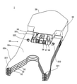
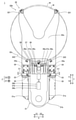
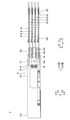
- FIG. 1 It is a figure which shows the structure of the substrate transfer robot by one Embodiment of this invention. It is a perspective view which shows the structure of the substrate holding hand by one Embodiment of this invention. It is a top view which shows the structure of the substrate holding hand by one Embodiment of this invention. It is a side view which shows the structure of the substrate holding hand by one Embodiment of this invention.
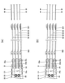
- (A) and (B) are diagrams for explaining the adjustment of the inclination of the blade according to the embodiment of the present invention.
- the configuration of the substrate transfer robot 100 according to the present embodiment will be described with reference to FIGS. 1 to 5.
- the board transfer robot 100 includes a board holding hand 1 and an arm 2 for moving the board holding hand 1.
- the substrate holding hand 1 supports the frame 31, the blade 32 that supports the substrate (semiconductor wafer) W, and the blade 32, and is attached to attach the blade 32 to the frame 31.
- It includes a member 33 and a tilt adjusting mechanism 34 that can adjust the tilt of the blade 32 in the horizontal direction in a lateral view by adjusting the tilt of the mounting member 33 with respect to the frame 31.
- the inclination adjusting mechanism 34 capable of adjusting the inclination of the blade 32 in the horizontal direction in the lateral view is provided. Even when the substrate W housed in the storage container (such as a hoop) is tilted with respect to the horizontal direction in a lateral view, the side of the blade 32 supporting the substrate W is aligned with the tilt of the substrate W with respect to the horizontal direction. The tilt with respect to the horizontal direction in the visual sense can be easily adjusted.
- the substrate W housed in the storage container is tilted with respect to the horizontal direction due to the tilt of the storage container itself, the substrate W is tilted in accordance with the tilt of the substrate W with respect to the horizontal direction.
- the inclination of the blade 32 supporting the substrate W with respect to the horizontal direction in the lateral view can be easily adjusted.
- the blade 32 is bent due to the weight of the blade 32 and the weight of the substrate W when the substrate W is held by the blade 32 and the blade 32 is tilted in the horizontal direction in the lateral view, it is horizontal.
- the inclination of the blade 32 supporting the substrate W with respect to the horizontal direction in the lateral view can be easily adjusted according to the inclination of the substrate W with respect to the direction.
- the board holding hand 1 includes a frame 31, a blade 32, a mounting member 33, and an inclination adjusting mechanism 34.
- the tilt adjusting mechanism 34 includes a tilt adjusting pin 34a.
- the tilt adjusting pin 34a is inserted into the mounting member 33, and the mounting member 33 extends laterally (X direction) orthogonal to the front-rear direction (Y direction) in which the frame 31 and the blade 32 are aligned in the horizontal direction. It is rotatably supported around the rotation axis C1 and is provided so as to extend laterally (X direction).
- the adjustment of the inclination of the blade 32 is exaggerated for the sake of easy understanding.
- the mounting member 33 includes a pair of mounting members 33 for mounting one side and the other side of the base end portion 32c of the blade 32 to the frame 31, respectively.
- the tilt adjusting pin 34a includes a pair of tilt adjusting pins 34a corresponding to the pair of mounting members 33.
- the tilt adjusting mechanism 34 can adjust the tilt of the blade 32 in the horizontal direction in the lateral view by rotating the pair of mounting members 33 around a predetermined rotation axis C1 with the pair of tilt adjusting pins 34a as the center of rotation. ..
- the inclination adjusting pin 34a is provided so as to be supported by the frame 31 and to protrude from the side of the frame 31 and be inserted into the mounting member 33.
- the tilt adjusting mechanism 34 rotates the mounting member 33 around a predetermined rotation axis C1 with the tilt adjusting pin 34a as the center of rotation, so that the mounting member 33 is framed by the fastening member 35 in a state where the tilt of the mounting member 33 is adjusted.
- the fastening member 35 is provided so as to extend in parallel with the predetermined rotation axis C1, and is attached to the frame 31 from the side (X direction) via the attachment member 33.
- the blade 32 includes a plurality of (4) blades 32 that each support the substrate W.
- the mounting member 33 commonly supports a plurality of blades 32.
- the tilt adjusting mechanism 34 can collectively adjust the tilt of the plurality of blades 32 in the horizontal direction by adjusting the tilt of the mounting member 33 with respect to the frame 31.
- the plurality of blades 32 are arranged side by side at a predetermined pitch in the direction (Z direction) perpendicular to the main surface 32a of the blades 32.
- the tilt adjusting mechanism 34 collectively tilts the plurality of blades 32 in the horizontal direction in a lateral view while maintaining the pitch between the plurality of blades 32 in the direction perpendicular to the main surface 32a of the blades 32 (Z direction). It is adjustable.
- the mounting member 33 is mounted on the side surface of the frame 31 from the side.
- the arm 2 is a horizontal articulated robot arm.
- the arm 2 includes a first arm 2a and a second arm 2b.
- the first arm 2a is configured to be rotatable with respect to a base 5 described later with one end as a rotation center.
- one end of the first arm 2a is rotatably connected to the base 5 via the first joint.
- the second arm 2b is configured to be rotatable with respect to the first arm 2a with one end as the center of rotation.
- one end of the second arm 2b is rotatably connected to the other end of the first arm 2a via a second joint.
- the substrate holding hand 1 is rotatably connected to the other end of the second arm 2b via a third joint.
- the servomotor which is the drive source for rotational drive
- the rotational position sensor that detects the rotational position of the output shaft of the servomotor
- the output of the servomotor are jointed.
- a drive mechanism including a power transmission mechanism for transmitting to is provided.
- the substrate transfer robot 100 further includes a base 5 to which the arm 2 is attached and an arm elevating mechanism 6 to which the base 5 is attached.
- the base 5 is configured such that one end is connected to one end of the first arm 2a and the other end is connected to the arm elevating mechanism 6.
- the arm elevating mechanism 6 is configured to raise and lower the arm 2 by raising and lowering the base 5.
- the arm elevating mechanism 6 includes a servomotor that is a drive source for elevating and lowering, a rotation position sensor that detects the rotation position of the output shaft of the servomotor, and a power transmission mechanism that transmits the output of the servomotor to the base 5 (arm 2). And include.
- the substrate holding hand 1 is provided with a plurality of (four) blades 32. That is, the substrate holding hand 1 is configured to be able to convey (hold) a plurality of (four) substrates W.
- the substrate holding hand 1 includes a frame 31, a blade 32, and a mounting member 33.
- the frame 31 is a support that supports the blade 32.
- the frame 31 includes a pair of side wall portions 31a and a base end portion 31b connecting the pair of side wall portions 31a.
- the pair of side wall portions 31a are provided apart from each other so that the wall surfaces face each other in a direction parallel to the direction in which the pair of front support portions 321 are arranged (X direction). Further, the pair of side wall portions 31a are provided so as to extend in a direction (Y direction) orthogonal to the direction in which the pair of front support portions 321 are arranged and parallel to the main surface 32a of the blade 32.
- the base end portion 31b connects each base end portion (a portion on the Y2 direction side) of the pair of side wall portions 31a.
- the proximal end portion 31b has a shape that is convexly curved toward the proximal end side (Y2 direction side).
- the pair of side wall portions 31a and the base end portion 31b are provided so as to form a U shape when viewed from a direction perpendicular to the main surface 32a of the blade 32.
- the blade 32 is a thin plate-shaped support plate that supports the substrate W.
- the blade 32 has a front support portion 321 provided on the tip end portion 32b side (Y1 direction side) and a rear support portion 322 provided on the base end portion 32c side (Y2 direction side). Further, the blade 32 has a shape in which the tip portion 32b side is bifurcated.
- a pair of front support portions 321 are separately provided for each of the bifurcated portions.
- the pair of front support portions 321 have a plurality (two) support surfaces provided at different heights from each other.
- the pair of rear support portions 322 have support surfaces provided at substantially the same height as the support surface on the lower side (Z2 direction side) of the pair of front support portions 321.
- the "height" means the distance from the main surface 32a of the blade 32 in the direction perpendicular to the main surface 32a of the blade 32 (Z direction).
- the pair of front support portions 321 and the pair of rear support portions 322 are provided on the main surface 32a of the blade 32.
- Each support surface of the pair of front support portions 321 and the pair of rear support portions 322 is configured to support the back surface (the surface on the Z2 direction side) of the outer peripheral edge portion of the substantially circular substrate W from below. ing.
- the mounting member 33 is mounted on the side wall portion 31a of the frame 31 from the side. Specifically, the mounting member 33 on the X1 direction side is mounted on the portion of the frame 31 on the side wall portion 31a on the X1 direction side on the tip end side from the outside side (X1 direction side). Further, the mounting member 33 on the X1 direction side is fixed to the portion on the tip end side of the side wall portion 31a on the X1 direction side of the frame 31 by the fastening member 35 on the X1 direction side. Further, the mounting member 33 on the X2 direction side is mounted on the portion of the frame 31 on the side wall portion 31a on the X2 direction side on the tip end side from the outside side (X2 direction side).
- the mounting member 33 on the X2 direction side is fixed to the tip end portion side of the side wall portion 31a on the X2 direction side of the frame 31 by the fastening member 35 on the X2 direction side.
- the fastening member 35 is inserted into the mounting member 33 in the X direction and is fastened to the fastening hole of the side wall portion 31a of the frame 31.
- the mounting member 33 has plate-shaped support portions 33a, 33b, and 33c that support the blade 32.
- the support portions 33a, 33b and 33c are arranged side by side in the direction perpendicular to the main surface 31c of the blade 32 (Z direction). Further, the support portions 33a, 33b and 33c are provided so as to extend from the frame 31 side (Y2 direction side) toward the tip end portion 32b side (Y1 direction side) of the blade 32.
- the support portion 33a supports the blade (first stage blade) 32 at the upper end (Z1 direction side) on the upper surface side.
- the support portion 33b commonly supports the intermediate blades (second-stage and third-stage blades) 32.
- the support portion 33b supports the blade 32 on each of the upper surface side and the lower surface side.
- the support portion 33c supports the blade (fourth stage blade) 32 at the lower end (Z2 direction side) on the lower surface side.
- the mounting member 33 is rotated around the rotation axis C1 with the tilt adjusting pin 34a as the center of rotation in a state where the fastening member 35 is loosened.
- the plurality of blades 32 supported by the support portions 33a, 33b and 33c of the mounting member 33 are rotated around the rotation axis C1 while maintaining the pitch between the plurality of blades 32.
- the inclinations of the plurality of blades 32 with respect to the horizontal direction in the lateral view are collectively adjusted.
- the inclination of the plurality of blades 32 with respect to the horizontal direction in the lateral view is fixed.
- the substrate holding hand 1 further includes a movable support unit 36 that moves forward and backward to support the substrate W, and a first movable pressing unit 37 and a second movable pressing unit 38 that move forward and backward to press the substrate W.
- the movable support unit 36 has a pair of support members 36a that support the substrate W, and an air cylinder 36b as an actuator for moving the pair of support members 36a forward and backward in the Y direction.
- the movable support unit 36 is configured so that the pair of support members 36a can be advanced in the Y1 direction by an air cylinder 36b and arranged at a support position that supports the substrate W.
- the movable support unit 36 is configured so that the pair of support members 36a can be retracted in the Y2 direction by the air cylinder 36b and arranged in a retracted position that does not support the substrate W.
- the pair of support members 36a have support surfaces provided at substantially the same height as the support surface on the upper side (Z1 direction side) of the pair of front support portions 321.
- Each support surface of the pair of support members 36a is configured to support the back surface (the surface on the Z2 direction side) of the outer peripheral edge portion of the substantially circular substrate W from below.
- the first movable pressing unit 37 has a pair of pressing members 37a for pressing the substrate W and an air cylinder 37b as an actuator for moving the pair of pressing members 37a forward and backward in the Y direction.
- the first movable pressing unit 37 is configured to be able to press the substrate W by advancing the pair of pressing members 37a in the Y1 direction by the air cylinder 37b. Further, the first movable pressing unit 37 is configured so that the pair of pressing members 37a can be retracted in the Y2 direction by the air cylinder 37b and arranged in a retracted position where the substrate W is not pressed.
- the second movable pressing unit 38 has a pair of pressing members 38a for pressing the substrate W and an air cylinder 38b as an actuator for moving the pair of pressing members 38a forward and backward in the Y direction.
- the second movable pressing unit 38 is configured to be able to press the substrate W by advancing the pair of pressing members 38a in the Y1 direction by the air cylinder 38b. Further, the second movable pressing unit 38 is configured so that the pair of pressing members 38a can be retracted in the Y2 direction by the air cylinder 38b and arranged in a retracted position where the substrate W is not pressed.
- the support surface on the upper side (Z1 direction side) of the pair of front support portions 321 and the support surface of the pair of support members 36a of the movable support unit 36 are the boards W after processing (after cleaning).
- the pair of pressing members 37a of the first movable pressing unit 37 are supported by the support surface on the upper side (Z1 direction side) of the pair of front support portions 321 and the support surface of the pair of support members 36a of the movable support unit 36.
- the treated substrate W after processing (after cleaning) is pressed.
- the support surface on the lower side (Z2 direction side) of the pair of front support portions 321 and the support surface of the pair of rear support portions 322 support the substrate W before processing (before cleaning). do.
- the pair of pressing members 38a of the second movable pressing unit 38 are supported by a support surface on the lower side (Z2 direction side) of the pair of front support portions 321 and a support surface of the pair of rear support portions 322. Press the substrate W before processing (before cleaning).
- the pair of front support portions 321 and the pair of rear support portions 322, the movable support unit 36, the first movable pressing unit 37, and the second movable pressing unit 38 are processed with the substrate W before processing (before cleaning). It can be used properly with the later (after cleaning) substrate W.
- the air cylinder 36b of the movable support unit 36, the air cylinder 37b of the first movable pressing unit 37, and the air cylinder 38b of the second movable pressing unit 38 are arranged inside the frame 31 as the frame inner parts 40a. ing. Further, the air cylinder 36b of the movable support unit 36, the air cylinder 37b of the first movable pressing unit 37, and the air cylinder 38b of the second movable pressing unit 38 are placed on the main surface 32a of the blade 32 inside the frame 31. They are arranged side by side in the vertical direction (Z direction).
- the air cylinder 36b of the movable support unit 36, the air cylinder 37b of the first movable pressing unit 37, and the air cylinder 38b of the second movable pressing unit 38 are in a direction perpendicular to the main surface 32a of the blade 32. It is provided so as to overlap when viewed from (Z direction). As a result, the air cylinders 36b, 37b and 38b are not arranged side by side in the width direction (X direction) of the frame 31, so that the air cylinders 36b, 37b and 38b can be compactly arranged in the width direction (X direction) of the frame 31. be.
- the substrate holding hand 1 further includes a cover (casing) 39 (see FIG. 2) provided separately from the frame 31.
- the cover 39 is provided so as to cover the frame 31 and a part of the movable support unit 36, the first movable pressing unit 37, and the second movable pressing unit 38 (a portion arranged inside the frame 31).
- the tilt adjusting mechanism 34 capable of adjusting the tilt of the blade 32 in the horizontal direction in the lateral view by adjusting the tilt of the mounting member 33 with respect to the frame 31, the storage container is provided. Even when the substrate W housed in (such as a hoop) is tilted with respect to the horizontal direction in the lateral view, the blade 32 supporting the substrate W is tilted in the lateral view according to the inclination of the substrate W with respect to the horizontal direction. The tilt with respect to the horizontal direction can be easily adjusted.
- the substrate W housed in the storage container is tilted with respect to the horizontal direction due to the tilt of the storage container itself, the substrate W is tilted in accordance with the tilt of the substrate W with respect to the horizontal direction.
- the inclination of the blade 32 supporting the substrate W with respect to the horizontal direction in the lateral view can be easily adjusted.
- the horizontal direction is also obtained.
- the inclination of the blade 32 supporting the substrate W with respect to the horizontal direction in the horizontal direction can be easily adjusted according to the inclination of the substrate W with respect to the substrate W.
- the tilt adjusting mechanism 34 includes the tilt adjusting pin 34a. Further, the inclination adjusting pin 34a is inserted into the mounting member 33, and the mounting member 33 is rotated around a predetermined rotation axis C1 extending in the horizontal direction orthogonal to the front-rear direction in which the frame 31 and the blade 32 are aligned. It is provided to support as much as possible and extend laterally. As a result, the mounting member 33 can be easily and surely rotated around a predetermined rotation axis C1 extending laterally with the tilt adjusting pin 34a as the center of rotation. Therefore, the blade 32 is provided by the tilt adjusting mechanism 34 including the tilt adjusting pin 34a. The horizontal tilt of the side view can be easily and surely adjusted.
- the mounting member 33 includes a pair of mounting members 33 for mounting one side and the other side of the base end portion 32c of the blade 32 to the frame 31, respectively.
- the tilt adjusting pin 34a includes a pair of tilt adjusting pins 34a corresponding to the pair of mounting members 33.
- the tilt adjusting mechanism 34 rotates the pair of mounting members 33 around a predetermined rotation axis C1 extending laterally with the pair of tilt adjusting pins 34a as the center of rotation, so that the blade 32 is viewed in the horizontal direction. The tilt can be adjusted.
- the pair of mounting members 33 can be more easily and surely rotated around the predetermined rotation axis C1 by using the pair of tilt adjusting pins 34a, so that the tilt adjusting mechanism 34 including the pair of tilt adjusting pins 34a can be rotated. Therefore, the inclination of the blade 32 with respect to the horizontal direction in the lateral view can be adjusted more easily and surely.
- the inclination adjusting pin 34a is provided so as to be supported by the frame 31 and to protrude from the side of the frame 31 and be inserted into the mounting member 33.
- the mounting member 33 can be rotated around a predetermined rotation axis C1 by the tilt adjusting pin 34a while the tilt adjusting pin 34a is firmly supported by the frame 31.
- the inclination of the blade 32 with respect to the horizontal direction in the lateral view can be easily adjusted.
- the tilt adjusting mechanism 34 adjusts the tilt of the mounting member 33 by rotating the mounting member 33 around a predetermined rotation axis C1 with the tilt adjusting pin 34a as the center of rotation.
- the mounting member 33 is fastened and fixed to the frame 31 by the fastening member 35, so that the inclination of the blade 32 with respect to the horizontal direction in the lateral view can be adjusted.
- the mounting member 33 can be fixed to the frame 31 by simply fastening and fixing the mounting member 33 to the frame 31, and the blade 32 can be fixed to an adjusted inclination with respect to the horizontal direction in the lateral view.
- the work of adjusting the inclination with respect to the horizontal direction can be easily performed.
- the blade 32 includes a plurality of blades 32 that each support the substrate W.
- the mounting member 33 commonly supports a plurality of blades 32.
- the inclination adjusting mechanism 34 can collectively adjust the inclination of the plurality of blades 32 in the horizontal direction in the lateral view by adjusting the inclination of the mounting member 33 with respect to the frame 31. This saves the trouble of adjusting the horizontal inclination of the plurality of blades 32 in the lateral view as compared with the case where it is necessary to individually adjust the horizontal inclination of the plurality of blades 32 in the lateral view. Therefore, it is possible to easily adjust the inclination of the plurality of blades 32 with respect to the horizontal direction in the lateral view.
- the plurality of blades 32 are arranged side by side at a predetermined pitch in the direction perpendicular to the main surface 32a of the blades 32.
- the tilt adjusting mechanism 34 collectively adjusts the tilts of the plurality of blades 32 with respect to the horizontal direction in the lateral view while maintaining the pitch between the plurality of blades 32 in the direction perpendicular to the main surface 32a of the blades 32. It is possible.
- the mounting member 33 is mounted on the side surface of the frame 31 from the side.
- the inclination of the mounting member 33 with respect to the horizontal direction in the lateral view can be easily adjusted from the side as compared with the case where the mounting member 33 is mounted from above or below the frame 31.
- By adjusting the inclination of the mounting member 33 it is possible to easily adjust the inclination of the blade 32 with respect to the horizontal direction in the lateral view.
- the arm is a horizontal articulated robot arm
- the present invention is not limited to this.
- the arm may be an arm other than the horizontal articulated robot arm such as a vertical articulated robot arm.
- the substrate holding hand may be provided with one blade.
- the substrate holding hand is provided with four blades, but the present invention is not limited to this.
- the board holding hand may be provided with a plurality of blades other than four.
- the blade has a bifurcated shape
- the present invention is not limited to this.
- the blade may have a shape other than the bifurcated shape.
- the blades are configured to be able to support two substrates at different heights, but the present invention is not limited to this.
- the blade may be configured to support only one substrate (only one height can support the substrate).
- the present invention is not limited to this.
- the movable support unit may not be provided.
- the movable support unit includes a pair of support members for one substrate, but the present invention is not limited to this.
- the movable support unit may include one support member for one substrate.
- the movable pressing unit includes a pair of pressing members
- the present invention is not limited to this.
- the movable pressing unit may include only one pressing member.
- the tilt adjusting mechanism includes a tilt adjusting pin
- the present invention is not limited to this.
- the tilt adjusting mechanism may include a tilt adjusting structure such as a tilt adjusting screw other than the tilt adjusting pin.
- the tilt adjusting mechanism can collectively adjust the tilt of a plurality of blades with respect to the horizontal direction in the lateral view, but the present invention is not limited to this.
- the tilt adjusting mechanism may be capable of individually adjusting the tilt of the plurality of blades with respect to the horizontal direction in the lateral view.
- the tilt adjusting mechanism may be capable of collectively adjusting the tilt of a part of the plurality of blades with respect to the horizontal direction in the lateral view.
Landscapes
- Engineering & Computer Science (AREA)
- Robotics (AREA)
- Mechanical Engineering (AREA)
- Container, Conveyance, Adherence, Positioning, Of Wafer (AREA)
- Manipulator (AREA)
Abstract
Description
本実施形態では、以下のような効果を得ることができる。
なお、今回開示された実施形態は、すべての点で例示であって制限的なものではないと考えられるべきである。本発明の範囲は、上記した実施形態の説明ではなく請求の範囲によって示され、さらに請求の範囲と均等の意味および範囲内でのすべての変更(変形例)が含まれる。
2 アーム
31 フレーム
32 ブレード
32a 主面
33 取付部材
34 傾き調整機構
34a 傾き調整ピン
35 締結部材
100 基板搬送ロボット
W 基板
C1 所定の回転軸線
Claims (9)
- フレームと、
基板を支持するブレードと、
前記ブレードを支持するとともに、前記ブレードを前記フレームに取り付けるための取付部材と、
前記フレームに対する前記取付部材の傾きを調整することにより、前記ブレードの側方視における水平方向に対する傾きを調整可能な傾き調整機構と、を備える、基板保持ハンド。 - 前記傾き調整機構は、傾き調整ピンを含み、
前記傾き調整ピンは、前記取付部材に挿入されるとともに、前記取付部材を水平方向のうち前記フレームと前記ブレードとが並ぶ前後方向に直交する側方に延びる所定の回転軸線周りに回転可能に支持し、前記側方に延びるように設けられている、請求項1に記載の基板保持ハンド。 - 前記取付部材は、前記ブレードの基端部の一方側および他方側を前記フレームにそれぞれ取り付けるための一対の取付部材を含み、
前記傾き調整ピンは、前記一対の取付部材に対応する一対の傾き調整ピンを含み、
前記傾き調整機構は、前記一対の傾き調整ピンを回転中心として前記一対の取付部材を前記所定の回転軸線周りに回転させることにより、前記ブレードの側方視における水平方向に対する傾きを調整可能である、請求項2に記載の基板保持ハンド。 - 前記傾き調整ピンは、前記フレームに支持されるとともに、前記フレームの側方から突出して前記取付部材に挿入されるように設けられている、請求項2に記載の基板保持ハンド。
- 前記傾き調整機構は、前記傾き調整ピンを回転中心として前記取付部材を前記所定の回転軸線周りに回転させることにより、前記取付部材の傾きを調整した状態で、締結部材により前記取付部材を前記フレームに締結固定することにより、前記ブレードの側方視における水平方向に対する傾きを調整可能である、請求項2に記載の基板保持ハンド。
- 前記ブレードは、前記基板を各々支持する複数のブレードを含み、
前記取付部材は、前記複数のブレードを共通に支持し、
前記傾き調整機構は、前記フレームに対する前記取付部材の傾きを調整することにより、前記複数のブレードの側方視における水平方向に対する傾きを一括して調整可能である、請求項1に記載の基板保持ハンド。 - 前記複数のブレードは、前記ブレードの主面に垂直な方向に所定のピッチで並んで配置されており、
前記傾き調整機構は、前記ブレードの主面に垂直な方向における前記複数のブレード間のピッチを維持した状態で、前記複数のブレードの側方視における水平方向に対する傾きを一括して調整可能である、請求項6に記載の基板保持ハンド。 - 前記取付部材は、前記フレームの側面に側方から取り付けられている、請求項1に記載の基板保持ハンド。
- 基板保持ハンドと、
前記基板保持ハンドを移動させるアームと、を備え、
前記基板保持ハンドは、
フレームと、
基板を支持するブレードと、
前記ブレードを支持するとともに、前記ブレードを前記フレームに取り付けるための取付部材と、
前記フレームに対する前記取付部材の傾きを調整することにより、前記ブレードの側方視における水平方向に対する傾きを調整可能な傾き調整機構と、を含む、基板搬送ロボット。
Priority Applications (4)
| Application Number | Priority Date | Filing Date | Title |
|---|---|---|---|
| CN202080103710.0A CN116325108B (zh) | 2020-09-03 | 2020-11-02 | 基板保持机械手和基板搬运机器人 |
| JP2022546870A JP7427796B2 (ja) | 2020-09-03 | 2020-11-02 | 基板保持ハンドおよび基板搬送ロボット |
| US18/024,419 US20230311339A1 (en) | 2020-09-03 | 2020-11-02 | Substrate holding hand and substrate conveying robot |
| KR1020237008333A KR102714310B1 (ko) | 2020-09-03 | 2020-11-02 | 기판 유지 핸드 및 기판 반송 로봇 |
Applications Claiming Priority (2)
| Application Number | Priority Date | Filing Date | Title |
|---|---|---|---|
| JP2020-148494 | 2020-09-03 | ||
| JP2020148494 | 2020-09-03 |
Publications (1)
| Publication Number | Publication Date |
|---|---|
| WO2022049787A1 true WO2022049787A1 (ja) | 2022-03-10 |
Family
ID=80490961
Family Applications (1)
| Application Number | Title | Priority Date | Filing Date |
|---|---|---|---|
| PCT/JP2020/041030 Ceased WO2022049787A1 (ja) | 2020-09-03 | 2020-11-02 | 基板保持ハンドおよび基板搬送ロボット |
Country Status (6)
| Country | Link |
|---|---|
| US (1) | US20230311339A1 (ja) |
| JP (1) | JP7427796B2 (ja) |
| KR (1) | KR102714310B1 (ja) |
| CN (1) | CN116325108B (ja) |
| TW (1) | TWI779382B (ja) |
| WO (1) | WO2022049787A1 (ja) |
Citations (7)
| Publication number | Priority date | Publication date | Assignee | Title |
|---|---|---|---|---|
| JPH11165863A (ja) * | 1997-12-02 | 1999-06-22 | Dainippon Screen Mfg Co Ltd | 基板搬送装置 |
| JPH11312723A (ja) * | 1998-04-30 | 1999-11-09 | Dainippon Screen Mfg Co Ltd | 基板搬送装置および方法 |
| JP2003019687A (ja) * | 2001-07-03 | 2003-01-21 | Aitec:Kk | ロボットハンドの駆動装置 |
| JP2007283436A (ja) * | 2006-04-17 | 2007-11-01 | Nachi Fujikoshi Corp | ロボット、ロボットシステム及びハンド装置の姿勢制御方法 |
| JP2010067871A (ja) * | 2008-09-12 | 2010-03-25 | Dainippon Screen Mfg Co Ltd | 基板搬送装置およびそれを備えた基板処理装置 |
| WO2017037976A1 (ja) * | 2015-09-03 | 2017-03-09 | 川崎重工業株式会社 | 基板移載装置 |
| JP2019519913A (ja) * | 2016-05-05 | 2019-07-11 | アプライド マテリアルズ インコーポレイテッドApplied Materials,Incorporated | 亀裂が低減されたロボットサブアセンブリ、エンドエフェクタアセンブリ、及び方法 |
Family Cites Families (9)
| Publication number | Priority date | Publication date | Assignee | Title |
|---|---|---|---|---|
| JP3802119B2 (ja) * | 1996-02-02 | 2006-07-26 | 株式会社安川電機 | ウェハ搬送装置 |
| WO2000005761A1 (en) * | 1998-07-24 | 2000-02-03 | Mitsubishi Denki Kabushiki Kaisha | Wafer holding hand |
| JP2003203962A (ja) | 2002-01-07 | 2003-07-18 | Kondo Seisakusho:Kk | ウエハ把持装置 |
| JP5578973B2 (ja) * | 2010-07-16 | 2014-08-27 | 日本電産サンキョー株式会社 | 産業用ロボット |
| JP5553065B2 (ja) | 2011-09-22 | 2014-07-16 | 株式会社安川電機 | 基板搬送用ハンドおよび基板搬送ロボット |
| US20180104827A1 (en) * | 2015-04-15 | 2018-04-19 | Kawasaki Jukogyo Kabushiki Kaisha | Substrate transfer robot and end effector of substrate transfer robot |
| JP7137047B2 (ja) * | 2018-03-15 | 2022-09-14 | シンフォニアテクノロジー株式会社 | Efem、及び、efemにおけるガス置換方法 |
| TWI805795B (zh) * | 2018-07-20 | 2023-06-21 | 美商應用材料股份有限公司 | 基板定位設備與方法 |
| JP7131334B2 (ja) * | 2018-11-29 | 2022-09-06 | 株式会社安川電機 | 基板支持装置、基板搬送ロボットおよびアライナ装置 |
-
2020
- 2020-11-02 JP JP2022546870A patent/JP7427796B2/ja active Active
- 2020-11-02 WO PCT/JP2020/041030 patent/WO2022049787A1/ja not_active Ceased
- 2020-11-02 CN CN202080103710.0A patent/CN116325108B/zh active Active
- 2020-11-02 TW TW109138070A patent/TWI779382B/zh active
- 2020-11-02 US US18/024,419 patent/US20230311339A1/en active Pending
- 2020-11-02 KR KR1020237008333A patent/KR102714310B1/ko active Active
Patent Citations (7)
| Publication number | Priority date | Publication date | Assignee | Title |
|---|---|---|---|---|
| JPH11165863A (ja) * | 1997-12-02 | 1999-06-22 | Dainippon Screen Mfg Co Ltd | 基板搬送装置 |
| JPH11312723A (ja) * | 1998-04-30 | 1999-11-09 | Dainippon Screen Mfg Co Ltd | 基板搬送装置および方法 |
| JP2003019687A (ja) * | 2001-07-03 | 2003-01-21 | Aitec:Kk | ロボットハンドの駆動装置 |
| JP2007283436A (ja) * | 2006-04-17 | 2007-11-01 | Nachi Fujikoshi Corp | ロボット、ロボットシステム及びハンド装置の姿勢制御方法 |
| JP2010067871A (ja) * | 2008-09-12 | 2010-03-25 | Dainippon Screen Mfg Co Ltd | 基板搬送装置およびそれを備えた基板処理装置 |
| WO2017037976A1 (ja) * | 2015-09-03 | 2017-03-09 | 川崎重工業株式会社 | 基板移載装置 |
| JP2019519913A (ja) * | 2016-05-05 | 2019-07-11 | アプライド マテリアルズ インコーポレイテッドApplied Materials,Incorporated | 亀裂が低減されたロボットサブアセンブリ、エンドエフェクタアセンブリ、及び方法 |
Also Published As
| Publication number | Publication date |
|---|---|
| TW202211366A (zh) | 2022-03-16 |
| JP7427796B2 (ja) | 2024-02-05 |
| KR102714310B1 (ko) | 2024-10-07 |
| CN116325108B (zh) | 2025-12-02 |
| CN116325108A (zh) | 2023-06-23 |
| JPWO2022049787A1 (ja) | 2022-03-10 |
| US20230311339A1 (en) | 2023-10-05 |
| TWI779382B (zh) | 2022-10-01 |
| KR20230048134A (ko) | 2023-04-10 |
Similar Documents
| Publication | Publication Date | Title |
|---|---|---|
| JP6374156B2 (ja) | 水平多関節ロボットおよび水平多関節ロボットの製造方法 | |
| KR102628862B1 (ko) | 기판을 반송하는 장치 및 기판을 처리하는 시스템 그리고 기판을 반송하는 방법 | |
| JP6058004B2 (ja) | マルチリンケージロボットを有するシステム及びマルチリンケージロボットにおいて位置アライメント及び回転アライメントを補正するための方法 | |
| JP5013281B2 (ja) | 移送ロボットおよび移送ロボットの制御方法 | |
| US6559461B1 (en) | Wafer scanning support unit of ion implantation apparatus | |
| KR101606223B1 (ko) | 산업용 로보트 | |
| CN117355399A (zh) | 具有角度柔顺机构的刀片型末端执行器 | |
| JP7427796B2 (ja) | 基板保持ハンドおよび基板搬送ロボット | |
| KR102512700B1 (ko) | 산업용 로봇 | |
| TW201834801A (zh) | 機器人之教示方法 | |
| JP2005026667A (ja) | 基板検出装置、基板検出方法、基板搬送装置および基板搬送方法、基板処理装置および基板処理方法 | |
| JP4029578B2 (ja) | ロボット | |
| JP7420954B2 (ja) | 基板保持ハンドおよび基板搬送ロボット | |
| WO2018096628A1 (ja) | 作業装置 | |
| JP3871535B2 (ja) | ロードポート装置及びこの装置と上位装置との取り付け機構 | |
| JP2000210889A (ja) | 産業用ロボット | |
| JP3916372B2 (ja) | ワーク搬送テーブル装置 | |
| JP7792205B2 (ja) | 高さ調整装置および製造装置 | |
| JP2000058625A (ja) | 基板搬送装置 | |
| CN211930765U (zh) | 用于摄像头模组的固定治具 | |
| JP2000254881A (ja) | ウェハー搬送用パラレルリンク機構ロボット | |
| WO2022049784A1 (ja) | 基板保持ハンドおよび基板搬送ロボット | |
| JPH11268829A (ja) | ローダ・アンローダ | |
| JP6486506B2 (ja) | 被実装物作業装置 | |
| WO2018096629A1 (ja) | 部品実装装置 |
Legal Events
| Date | Code | Title | Description |
|---|---|---|---|
| 121 | Ep: the epo has been informed by wipo that ep was designated in this application |
Ref document number: 20952521 Country of ref document: EP Kind code of ref document: A1 |
|
| ENP | Entry into the national phase |
Ref document number: 2022546870 Country of ref document: JP Kind code of ref document: A |
|
| ENP | Entry into the national phase |
Ref document number: 20237008333 Country of ref document: KR Kind code of ref document: A |
|
| NENP | Non-entry into the national phase |
Ref country code: DE |
|
| 122 | Ep: pct application non-entry in european phase |
Ref document number: 20952521 Country of ref document: EP Kind code of ref document: A1 |