WO2022044688A1 - コネクタ - Google Patents
コネクタ Download PDFInfo
- Publication number
- WO2022044688A1 WO2022044688A1 PCT/JP2021/028206 JP2021028206W WO2022044688A1 WO 2022044688 A1 WO2022044688 A1 WO 2022044688A1 JP 2021028206 W JP2021028206 W JP 2021028206W WO 2022044688 A1 WO2022044688 A1 WO 2022044688A1
- Authority
- WO
- WIPO (PCT)
- Prior art keywords
- locking
- lever
- housing
- locking portion
- temporary
- Prior art date
Links
- 230000000630 rising effect Effects 0.000 claims description 29
- 230000013011 mating Effects 0.000 claims description 12
- 230000002093 peripheral effect Effects 0.000 description 15
- 238000005452 bending Methods 0.000 description 13
- 229920003002 synthetic resin Polymers 0.000 description 3
- 239000000057 synthetic resin Substances 0.000 description 3
- 230000015572 biosynthetic process Effects 0.000 description 2
- 230000001154 acute effect Effects 0.000 description 1
- 210000000078 claw Anatomy 0.000 description 1
- 230000003028 elevating effect Effects 0.000 description 1
- 230000008030 elimination Effects 0.000 description 1
- 238000003379 elimination reaction Methods 0.000 description 1
- 210000004185 liver Anatomy 0.000 description 1
- 239000002184 metal Substances 0.000 description 1
- 238000000034 method Methods 0.000 description 1
- 238000012986 modification Methods 0.000 description 1
- 230000004048 modification Effects 0.000 description 1
- 230000000717 retained effect Effects 0.000 description 1
- 238000000638 solvent extraction Methods 0.000 description 1
Images


Classifications
-
- H—ELECTRICITY
- H01—ELECTRIC ELEMENTS
- H01R—ELECTRICALLY-CONDUCTIVE CONNECTIONS; STRUCTURAL ASSOCIATIONS OF A PLURALITY OF MUTUALLY-INSULATED ELECTRICAL CONNECTING ELEMENTS; COUPLING DEVICES; CURRENT COLLECTORS
- H01R13/00—Details of coupling devices of the kinds covered by groups H01R12/70 or H01R24/00 - H01R33/00
- H01R13/62—Means for facilitating engagement or disengagement of coupling parts or for holding them in engagement
- H01R13/629—Additional means for facilitating engagement or disengagement of coupling parts, e.g. aligning or guiding means, levers, gas pressure electrical locking indicators, manufacturing tolerances
- H01R13/62933—Comprising exclusively pivoting lever
- H01R13/62955—Pivoting lever comprising supplementary/additional locking means
-
- H—ELECTRICITY
- H01—ELECTRIC ELEMENTS
- H01R—ELECTRICALLY-CONDUCTIVE CONNECTIONS; STRUCTURAL ASSOCIATIONS OF A PLURALITY OF MUTUALLY-INSULATED ELECTRICAL CONNECTING ELEMENTS; COUPLING DEVICES; CURRENT COLLECTORS
- H01R13/00—Details of coupling devices of the kinds covered by groups H01R12/70 or H01R24/00 - H01R33/00
- H01R13/62—Means for facilitating engagement or disengagement of coupling parts or for holding them in engagement
- H01R13/629—Additional means for facilitating engagement or disengagement of coupling parts, e.g. aligning or guiding means, levers, gas pressure electrical locking indicators, manufacturing tolerances
- H01R13/62933—Comprising exclusively pivoting lever
- H01R13/62938—Pivoting lever comprising own camming means
Definitions
- This disclosure relates to connectors.
- the connector disclosed in Patent Document 1 includes a housing and a lever rotatably supported by the housing.
- the housing has a housing-side locking portion that is flexible and deformable.
- the lever has a lever-side locking portion. By locking the lever-side locking portion to the housing-side locking portion, the lever is stopped at the temporary locking position with respect to the housing.
- This type of connector is also disclosed in Patent Document 2.
- the locking portion on the lever side and the locking portion on the housing side may be disengaged. If the lever-side locking portion and the housing-side locking portion are completely unlocked, the lever rotates, so that the operator can notice that the lever is not in the locked state. However, in a state where the housing-side locking portion is flexed and deformed, the lever may remain incompletely in the temporary locking position while the lever-side locking portion is in contact with the protruding portion of the housing-side locking portion in a face-to-face manner. .. Since it is difficult to grasp this state, the operator may rotate a lever that is not in the locked state at the temporarily locked position. Then, it is not possible to obtain a modest release feeling that is felt when the lever is released from the locked state, and there is a possibility that the connector fitting work cannot be properly proceeded.
- the connectors of the present disclosure include a housing and a lever that is supported by the housing and rotates from a temporary locking position to the main locking position to advance fitting between the housing and the mating housing.
- One of the levers and the lever is provided with a flexible and deformable first locking portion, and the other is provided with a second locking portion.
- the first locking portion includes a first top portion and the above. It has a first locking surface connected to a first top portion, and the second locking portion has a second locking surface that is in contact with the first locking portion and stops the lever at the temporary locking position.
- the second locking surface has, in a state where the first locking portion is bent due to the interference between the first top portion and the second locking portion, the first locking surface is formed from the first top portion.
- a connector with tilted sides that are tilted to the side.
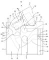
- FIG. 1 is a side view showing a state in which the lever is arranged closer to one end side of the play range of the temporary locking position with respect to the housing in the connector of the first embodiment.
- FIG. 2 is a plan view showing a state in which the lever is arranged closer to one end side of the play range of the temporary locking position with respect to the housing.
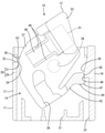
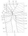
- FIG. 3 is a fracture plan view showing a state in which the lever is arranged closer to the other end side of the play range of the temporary locking position with respect to the housing, and the first locking surface and the second locking surface are in contact with each other. .. FIG.
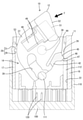
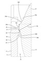
- FIG. 4 shows a state in which the lever rotates on the other end side of the play range of the temporary locking position, and the first locking portion is temporarily bent due to the interference between the first top portion and the second locking portion. It is a fracture plan view.
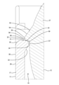
- FIG. 5 is an enlarged cross-sectional view of the first locking portion and the second locking portion in the state shown in FIG.
- FIG. 6 is an enlarged cross-sectional view of the first locking portion and the second locking portion in the state shown in FIG.
- FIG. 7 is a plan view of the lever.
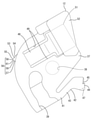
- FIG. 8 is a front view of the mating housing.
- FIG. 9 is an enlarged cross section showing a state in which the first top portion of the first locking portion and the second locking surface are in contact with each other and locked when the lever is in the temporary locking position in the connector of the second embodiment. It is a figure.
- FIG. 10 is an enlarged cross-sectional view showing a state in which the first locking portion is temporarily bent from the state shown in FIG.
- the connectors of this disclosure are (1) A housing and a lever supported by the housing and rotating from a temporary locking position to a main locking position to advance fitting between the housing and the mating housing are provided, and the housing and the lever are provided. One of them is provided with a flexible and deformable first locking portion, and the other is provided with a second locking portion.
- the first locking portion includes a first top portion and the first top portion.
- the second locking portion has a second locking surface that is in contact with the first locking portion and stops the lever at the temporary locking position.
- the second locking surface is inclined from the first top portion to the first locking surface side in a state where the first locking portion is bent due to interference between the first top portion and the second locking portion. It has an inclined side that is arranged in a row. If the lever is inadvertently rotated within the play range of the temporary locking position, the first locking portion is temporarily bent due to the interference between the first top portion and the second locking portion. However, since the second locking surface of the second locking portion has an inclined side, it can be displaced to the side facing the first locking surface by receiving the pressing force of the first top portion. Therefore, the first locking portion and the second locking portion can be quickly returned to the lockable state, and the bending of the first locking portion can be automatically eliminated.
- the "side” referred to in the present specification means a side on a surface in a cross section intersecting with a surface, and includes not only a line segment but also a curve. Further, in the definition of the "side” of the line connecting the vertices, the "vertex" may be formed by a curve (curved surface).
- the second locking portion includes a second rising surface arranged on the opposite side of the second locking surface, and a top portion arranged between the second rising surface and the inclined side. It is preferable to have. According to this, the inclination angle and the formation range of the inclined side can be easily adjusted by changing the relative position of the top portion with respect to the first locking portion.
- the second locking surface has a locking side that intersects the inclined side via the second top portion, and the locking side has the first locking portion at the temporary locking position.
- the first locking surface is arranged so as to be in contact with the first locking surface so as to be inclined more gently than the inclined side or to face each other in parallel. According to this, even if the second locking surface has an inclined side, the locking side can be in good contact with the first locking surface. Therefore, the locking force of the second locking portion with respect to the first locking portion can be maintained or increased.
- the housing has a housing-side locking portion
- the lever has a lever-side locking portion that is locked to the housing-side locking portion at the temporary locking position, and the housing side.
- One of the locking portion and the lever-side locking portion can be flexed and deformed, and the locked state of the housing-side locking portion and the lever-side locking portion is released by the unlocking portion of the mating housing.
- a gap is formed between the lever-side locking portion and the housing-side locking portion, and the lever allows the lever to bend with respect to the housing at the temporary locking position. It is good that it is in a state where it can rotate within the range of.
- the lever is easily rotated in the play range of the temporary locking position including the above-mentioned gap, and the locked state of the lever in the temporary locking position is easily released.
- the second locking surface is not limited to the first top portion, and the first locking portion and the second locking portion are engaged. Since the lever can be returned to the stoptable state, the locked state of the lever can be satisfactorily secured.
- the connector 10 includes a housing 11 and a lever 12 rotatably supported by the housing 11.
- the housing 11 is fitted to the mating housing 100.
- the lever 12 rotates from the temporary locking position to the main locking position with respect to the housing 11 to advance the fitting of both housings 11 and 100.
- the surface side where the housings 11 and 100 face each other at the start of fitting is the front side.
- the vertical direction is based on the vertical direction of FIGS. 1 and 8.
- the width direction is based on the left-right direction of each figure except FIG.
- the mating housing 100 is made of synthetic resin and has a square tubular hood portion 110 that opens forward, as shown in FIGS. 4 and 8.
- the hood portion 110 has a columnar cam follower 111 projecting downward at the center of the inner surface of the upper wall in the width direction.
- the hood portion 110 has a rib-shaped release portion 112 that protrudes downward and extends in the front-rear direction at one end in the width direction of the inner surface of the upper wall.
- the hood portion 110 has a pair of guide portions 113 that protrude from each other and extend in the front-rear direction at the upper ends of the inner surfaces of the left and right side wall portions.
- a plurality of male terminal fittings 120 are projected and arranged in the hood portion 110.
- Each male terminal fitting 120 has a tab shape and is arranged vertically and horizontally in a space below the guide portion 113 in the hood portion 110.
- the housing 11 is made of synthetic resin and is formed in a square block shape as a whole. As shown in FIG. 4, the housing 11 is fitted in the hood portion 110. As shown in FIG. 1, a plurality of female terminal fittings 20 (only one is shown in FIG. 1) are housed in the housing 11. Each female terminal fitting 20 is arranged at a position corresponding to each male terminal fitting 120. The female terminal fitting 20 is connected to the end of the electric wire 90.
- the housing 11 has a pair of guide grooves 13 (only one is shown in FIG. 1) extending in the front-rear direction and opening forward at the upper ends of the left and right side walls 16 and 17 (reference numeral 17 side in FIG. 1). There is. By inserting the guide portion 113 into the guide groove 13, the fitting operation of both housings 11 and 100 is guided.
- the housing 11 has an accommodating portion 14 capable of accommodating the lever 12 at the upper end portion.
- the accommodating portion 14 is provided above the cavity region for accommodating each female terminal fitting 20.
- the accommodating portion 14 is partitioned by left and right side walls 16 and 17 of the housing 11 and a top wall 18 (see FIG. 2).
- the housing 11 has a lock portion 19 projecting into the accommodating portion 14.
- a support shaft 62 for supporting the lever 12 is projected and arranged in the accommodating portion 14.
- the top wall 18 is formed in a flat plate shape. As shown in FIG. 2, the top wall 18 has an introduction groove 21 extending in the front-rear direction and opening forward in the central portion in the width direction.
- the support shaft 62 is arranged behind the introduction groove 21.
- the top wall 18 has a receiving groove 22 extending in the front-rear direction and opening forward at one end in the width direction.
- the receiving groove 22 has a groove width smaller than that of the introduction groove 21, and is formed longer than the introduction groove 21 in the front-rear direction.
- the introduction groove 21 has a role of passing the cam follower 111 and guiding the lever 12 to the cam groove 39 described later.
- the release portion 112 enters the receiving groove 22.
- the top wall 18 has a thick stopper portion 23 protruding along the rear end of the top wall 18 on one side in the width direction.
- the stopper portion 23 has a recess 24 recessed forward in the central portion in the width direction of the rear end of the top wall 18.
- the top wall 18 has a concave retracting portion 25 that is largely recessed in front of the stopper portion 23 on the other side in the width direction of the rear end.
- the lock portion 19 can be visually recognized from above through the inside of the retracting portion 25.
- the side wall 16 on one side in the width direction has a housing-side locking portion 26 protruding into the accommodating portion 14.
- the housing-side locking portion 26 can be visually recognized from above through the receiving groove 22.
- the housing-side locking portion 26 is formed in a trapezoidal shape.
- the inner surface, which is the protruding end of the housing-side locking portion 26, is arranged linearly along the front-rear direction.
- the front surface of the housing-side locking portion 26 is inclined so that the protruding end side projects forward.
- the side wall 17 on the other side in the width direction has a pair of upper and lower slits 27 at the upper end portion for partitioning the accommodating portion 14. Both slits 27 extend in the front-rear direction and are opened rearward on the rear end side of the upper end portion of the side wall 17.
- the housing 11 has a first locking portion 28 between the slits 27 at the upper end of the side wall 17.
- the first locking portion 28 has an elastic portion 29 extending from the front end between the slits 27 in a cantilevering manner to the rear, and a locking projection 31 protruding from the rear end portion of the elastic portion 29 into the accommodating portion 14. is doing.
- the elastic portion 29 constitutes a part of the side wall 17 and is formed with a constant thickness.
- the elastic portion 29 can be flexed and deformed inward and outward with the front end portion as a fulcrum. As shown in FIGS. 3 and 5, the elastic portion 29 is naturally arranged along the front-rear direction.
- the locking projection 31 is arranged between the first locking surface 32, the first rising surface 33, and the first locking surface 32 and the first rising surface 33. It has a first top 34 and.
- the first locking surface 32 is connected to the outer surface of the elastic portion 29 (the outer surface of the side wall 17) via the curved portion 35, and is arranged linearly in a direction intersecting the outer surface of the elastic portion 29. As shown in FIG. 5, when the elastic portion 29 is in the natural state, the first locking surface 32 is arranged along the width direction.
- the first rising surface 33 is connected to the inner surface of the elastic portion 29 (inner surface of the side wall 17), and is linearly inclined inward in the width direction so as to go deeper into the accommodating portion 14 toward the rear with respect to the inner surface of the elastic portion 29. is doing.
- the surface direction of the first rising surface 33 and the surface direction of the first locking surface 32 intersect each other at an acute angle with the first top portion 34 interposed therebetween.
- the first top portion 34 is curved in an arc shape from the first locking surface 32 to the first rising surface 33.
- the first top portion 34 intersects the first locking surface 32 and the first rising surface 33, and is formed on a curved surface having a radius of curvature smaller than that of the curved portion 35.
- the curved surface portion 36 and the first locking surface 32 facing the rear in the first top portion 34 are when the housing 11 is viewed from the rear in a state where the lever 12 is not assembled in the accommodating portion 14. Can be visually recognized.
- the lever 12 is made of synthetic resin and has a single plate-shaped lever body 37 as shown in FIG. 7.
- the lever body 37 has a bearing portion 38 that opens to the lower plate surface.
- the support shaft 62 is fitted in the bearing portion 38.
- the lever 12 is rotatable about the support shaft 62 fitted in the bearing portion 38 between the temporary locking position and the main locking position.
- the lever body 37 has a cam groove 39 that opens on the upper plate surface.
- the cam groove 39 is open on the outer peripheral edge of the lever body 37.
- the cam follower 111 of the mating housing 100 enters the entrance of the cam groove 39.
- the cam follower 111 slides into contact with the groove surface of the cam groove 39, the mating housing 100 is pulled to the housing 11, and both housings 11 and 100 are fitted. The case progresses.
- the cam follower 111 is arranged on the inner end side of the cam groove 39, and both housings 11 and 100 are in a state of being normally fitted.
- each female terminal fitting 20 and each male terminal fitting 120 are electrically connected.
- the lever body 37 has a lever-side locking portion 42 that cantilevers rearward from the base end portion 41 near the entrance of the cam groove 39 on the outer peripheral edge.
- the lever-side locking portion 42 includes an extending portion 43 arranged linearly from the base end portion 41, and a locking main body 44 projecting diagonally outward with respect to the extending portion 43. have.
- the extending portion 43 can be flexed and deformed inward and outward in the width direction with the base end portion 41 as a fulcrum.
- the locking body 44 has a locking recess 45 having an L-shaped notch at the corner of the rear end. As shown in FIG. 3, the locking recess 45 faces the tip angle region 46 formed from the inner surface to the front surface of the housing-side locking portion 26 at the temporary locking position.
- the locking main body 44 has a relief recess 47 having a shape in which the lower surface side is notched diagonally at the corner of the front end.
- the lever body 37 has a lock arm 48 on the side opposite to the side having the bearing portion 38, the cam groove 39, and the lever side locking portion 42 in the width direction.
- the lock arm 48 is flexibly and deformably arranged between a pair of notches 49 formed in the lever body 37.
- the lock arm 48 is locked to the lock portion 19 (see FIG. 2) at this locking position. Both housings 11 and 100 are held in a fitted state by locking the lock arm 48 and the lock portion 19.
- the front portion of the lock arm 48 is arranged in the retracting portion 25 at the main locking position. As a result, interference between the lock arm 48 and the top wall 18 is avoided.
- the lock arm 48 has a lock release portion 51 extended in the width direction at the rear end portion (the rear end portion at the main locking position).
- the lock arm 48 and the lock portion 19 are unlocked by pressing the lock release portion 51.
- the lever 12 is rotated to the temporary locking position side, so that the lever 12 can return from the main locking position to the temporary locking position. There is.
- the lever 12 has a bridge-shaped erection portion 52 at the rear end of the lever body 37.
- the erection portion 52 covers the outside of the lock release portion 51 to regulate an inadvertent release operation to the lock release portion 51.
- the inner edge portion of the erection portion 52 is formed in a protruding shape that fits into the recess 24 of the stopper portion 23 at the temporary locking position.
- the lever 12 has a second locking portion 53 protruding from the outer peripheral edge of the lever body 37.
- the second locking portion 53 is arranged at a position closer to the front end portion of the lock arm 48.
- the second locking portion 53 is formed in a claw shape.
- the thickness of the second locking portion 53 is formed to be constant within the thickness range of the lever body 37. As shown in FIG. 7, the second locking portion 53 has a second rising surface 54, a top portion 55, and a second locking surface 56.
- the top portion 55 is formed at the tip of the second locking portion 53 in the protruding direction.
- the top portion 55 is a portion where the second rising surface 54 and the second locking surface 56 intersect, and is configured as an obtuse angle top angle portion between the second rising surface 54 and the second locking surface 56. ..
- the second rising surface 54 is connected to the top 55 on the side opposite to the side where the lever 12 rotates to the main locking position (rear side). As shown in FIG. 6, the second rising surface 54 is linearly arranged at a constant inclination angle from the connecting position 70 on the outer peripheral edge of the lever body 37 to the top 55. The second rising surface 54 is a slope having a gentle inclination angle with respect to the tangential direction at the connecting position 70 of the outer peripheral edge of the lever main body 37.
- the second locking surface 56 is connected to the top 55 on the side (front side) where the lever 12 rotates to the main locking position. As shown in FIG. 6, the second locking surface 56 has a curved side 57 connected to the connecting position 80 of the outer peripheral edge of the lever main body 37. The curved side 57 has a U-shaped recess when viewed from the front.
- the second locking surface 56 has an inclined side 58 and a locking side having different inclination angles with respect to the tangential direction at the connecting position 80 of the outer peripheral edge of the lever body 37 between the curved side 57 and the top portion 55. Has 59. Further, the second locking surface 56 has a second top portion 61 between the inclined side 58 and the locking side 59.
- the locking side 59 is linearly arranged at a constant inclination angle from the curved side 57 to the inclined side 58.
- the locking side 59 forms a right angle or an angle close to a right angle with respect to the tangential direction at the connecting position of the outer peripheral edge of the lever body 37.
- the inclined side 58 is linearly arranged at a constant inclination angle from the second apex 61 to the apex 55.
- the inclined side 58 is an inclined surface having a gentle inclined angle of 45 degrees or less with respect to the tangential direction at the connecting position of the outer peripheral edge of the lever main body 37.
- the inclined side 58 is arranged between the top 55 and the second top 61, and is obtusely connected to the second rising surface 54 via the top 55.
- the inclined side 58 is obtusely connected to the locking side 59 via the second top portion 61.
- the length of the inclined side 58 (the length in the inclined direction) is smaller than the length of the locking side 59.
- the length of the second rising surface 54 is larger than the sum of the length of the inclined side 58 and the length of the locking side 59.
- the lever 12 may rotate within a play range with respect to the housing 11 at the temporary locking position.
- the inner edge portion of the erection portion 52 is fitted into the recess 24 of the stopper portion 23 and is arranged so as to be lockable. Liver.
- the lever 12 is restricted from rotating from the temporary locking position to the side opposite to the main locking position.
- the locking recess 45 of the lever-side locking portion 42 is arranged away from the tip angle region 46 of the housing-side locking portion 26.
- the second locking surface 56 of the second locking portion 53 is also arranged away from the first locking surface 32 of the first locking portion 28.
- the locking recess 45 of the lever-side locking portion 42 is the housing-side locking portion 26. It fits into the tip angle region 46 and is arranged so as to be lockable.
- the locking side 59 of the second locking surface 56 is arranged so as to face the first locking surface 32 and can be locked. Specifically, the locking side 59 of the second locking surface 56 is arranged so as to be in contact with the tip region (the region on the first top 34 side) of the first locking surface 32 at a gentle inclination angle or in parallel. To. This restricts the lever 12 from rotating from the temporary locking position to the main locking position.
- the entrance of the cam groove 39 communicates with the introduction groove 21.
- the housing 11 is shallowly fitted in the mating housing 100.
- the cam follower 111 is arranged at the entrance of the introduction groove 21 and the cam groove 39.
- the release portion 112 When the housing 11 is shallowly fitted to the mating housing 100, the release portion 112 is inserted into the receiving groove 22. The tip of the release portion 112 abuts against the locking body 44 of the lever-side locking portion 42, the locking body 44 is pressed against the release portion 112, and the extension portion 43 is bent and deformed. The bending of the extending portion 43 is allowed within the play range (gap 60) of the temporary locking position. When the extending portion 43 bends and deforms, the interference between the tip angle region 46 of the housing side locking portion 26 and the locking body 44 is avoided by the relief recess 47.
- the operator presses the erection portion 52 or the like to rotate the lever 12 from the temporary locking position to the main locking position.
- the second locking portion 53 presses the first locking portion 28
- the elastic portion 29 bends and deforms, the second top portion 61 gets over the first top portion 34, and the elastic portion 29 Deflection is eliminated.
- the elastic portion 29 abuts on the outer peripheral edge of the lever 12 as it returns elastically, and emits a collision sound.
- the operator released the locked state of the lever 12 in the temporary locking position by listening to the collision sound or by feeling the change in the operating force due to the elimination of the bending of the elastic portion 29. You can recognize that.
- the lever 12 reaches the main locking position, and the lock arm 48 locks the lock portion 19, so that both housings 11 and 100 are held in a normally fitted state.
- the bending of the elastic portion 29 is eliminated when the operator performs the rotation operation of the lever 12.
- the inclined side 58 of the second locking surface 56 is formed on the first top portion 34 of the locking projection 31. Contact.
- the inclined side 58 is arranged to be inclined so as to face the curved surface portion 36 and the first locking surface 32 side from the first top portion 34 in the front-rear direction.
- the elastic portion 29 tries to elastically recover from the bent state in the returning direction in which the bending is eliminated.
- the first top portion 34 presses the inclined side 58 of the second locking surface 56 in the returning direction of the elastic portion 29.
- a pressing force P acts on the second locking portion 53 in a direction perpendicular to the surface direction of the inclined side 58, and a rearward component force P1 is further applied as a component force component of the pressing force P. It works. Therefore, the second locking portion 53 is displaced rearward with respect to the first top portion 34 by the component force P1.
- the first top portion 34 slides on the inclined side 58 and is displaced toward the second top portion 61 side. In this way, the bending of the elastic portion 29 is automatically eliminated.
- the elastic portion 29 returns to the natural state.
- the first locking surface 32 faces the locking side 59 of the second locking surface 56 so as to be lockable.
- the first top portion 34 is set to be in contact with the inclined side 58 even when the elastic portion 29 is maximally bent within the play range of the temporary locking position. .. Therefore, no matter how the elastic portion 29 bends within the play range of the temporary locking position of the lever 12, the first locking portion 28 and the second locking portion 53 can be locked by the inclined side 58. be able to.
- the lever 12 is temporarily engaged. Even if the elastic portion 29 of the first locking portion 28 is temporarily bent due to careless rotation within the play range of the stop position, the second locking surface 56 is the first locking surface 32.
- the first locking portion 28 and the second locking portion 53 can be returned to a lockable state by being displaced to the side facing the surface. As a result, the bending of the elastic portion 29 can be automatically eliminated. Therefore, when the operator starts the rotation operation of the lever 12, it is guaranteed that the first locking surface 32 and the second locking surface 56 face each other in a lockable manner. As a result, the operator can feel the state in which the bending of the first locking portion 28 is eliminated with moderation, and can appropriately proceed with the rotation operation of the lever 12.
- the lever-side locking portion 42 when the lever 12 is in the temporary locking position, the lever-side locking portion 42 is allowed to bend between the lever-side locking portion 42 and the housing-side locking portion 26. There is a circumstance that the gap 60 is formed and the play range including the gap 60 becomes large. Therefore, since the lever 12 easily rotates within the play range of the temporary locking position, the above configuration is adopted so that the first locking portion 28 and the second locking portion 53 can return to the lockable state. The merit of doing it is great.
- the second locking portion 53 has the top portion 55 between the inclined side 58 and the second rising surface 54, the relative position of the top top 55 with respect to the first locking portion 28 can be changed. , The inclination angle and the formation range of the inclined side 58 can be easily adjusted.
- the second locking surface 56 has an inclined side 58 and a locking side 59 via the second top portion 61, and at the temporary locking position, the locking side 59 has an inclined side 58 with respect to the first locking surface 32. It can be tilted more gently or can be in parallel and facing each other. Therefore, the locking force of the second locking portion 53 with respect to the first locking portion 28 can be satisfactorily secured.
- Embodiment 2 of the present disclosure will be described with reference to FIGS. 9 and 10.
- the shape of the second locking portion 53A is different from that of the first embodiment.
- Others are the same as those in the first embodiment.
- the same or corresponding structures as those in the first embodiment are designated by the same reference numerals, and duplicate description will be omitted.
- the second locking portion 53A has a triangular cross section and protrudes from the outer peripheral edge of the lever body 37.
- the second locking portion 53A has a top 55A at the tip in the protruding direction, a second rising surface 54A behind the top 55A, and a second locking surface 56A in front of the top 55A. There is.
- the top portion 55A is a portion where the second rising surface 54A and the second locking surface 56A intersect, and is configured as an obtuse angle top angle portion between the second rising surface 54A and the second locking surface 56A. ..
- the second rising surface 54A is linearly arranged at a constant inclination angle from the connecting position 70A on the outer peripheral edge of the lever body 37 to the top 55A.
- the second rising surface 54A is a slope having a gentle inclination angle with respect to the tangential direction at the connecting position 70A of the outer peripheral edge of the lever main body 37.
- the length of the second rising surface 54A (the length in the inclined direction) is smaller than the length of the second rising surface 54A of the first embodiment.
- the second locking surface 56A is linearly arranged at a constant inclination angle from the connecting position 80A on the outer peripheral edge of the lever body 37 to the top 55A.
- the second locking surface 56A is entirely configured as an inclined side 58A.
- the second locking surface 56A does not have a portion corresponding to the second top portion 61 of the first embodiment.
- the second locking surface 56A is a slope having a gentle inclination angle of 45 degrees ( ⁇ / 4) or less with respect to the tangential direction at the connecting position 80A of the outer peripheral edge of the lever body 37 as a whole.
- the tilt angle of the second locking surface 56A is the same as or close to the tilt angle of the first locking surface 32.
- the inclination angle of the second locking surface 56A is larger than the inclination angle of the inclined side 58A of the first embodiment and smaller than the inclination angle of the locking side 59 of the first embodiment.
- the length of the second locking surface 56A is smaller than the length of the second rising surface 54A.
- the first top portion 34 is in contact with the second locking surface 56A. ..
- the elastic portion 29 is flexed and deformed to the maximum extent, the first top portion 34 comes into contact with the rear portion of the second locking surface 56A.
- the pressing force PA caused by the bending of the elastic portion 29 and the component force PA1 as a component force component of the pressing force PA act on the second locking portion 53A.
- the second locking portion 53A is displaced rearward with respect to the first top portion 34 by the component force PA1.
- the first top portion 34 displaces the inclined side 58A forward.
- the first top portion 34 is displaced toward the front portion of the second locking surface 56A.
- the first top portion 34 is a portion that faces the second locking surface 56A so as to be able to be locked at the temporary locking position.
- the second locking surface 56A is an inclined side 58A and is also a portion that faces the first top portion 34 so as to be lockable. Therefore, according to the second embodiment, a state in which the first locking portion 28 and the second locking portion 53A are locked at the temporary locking position is appropriately constructed.
- the embodiments disclosed this time are exemplary in all respects and not restrictive.
- the first locking portion that can be flexed and deformed is provided in the housing, and the second locking portion that cannot be flexed and deformed is provided in the lever.
- a possible first locking portion may be provided on the lever and a second locking portion that cannot be bent and deformed may be provided on the housing.
- the lever-side locking portion is made flexible and deformable, and the housing-side locking portion has rigidity that does not bend and deform.
- the lever-side locking portion is It may have a rigidity that does not bend and deform, and the locking portion on the housing side may be configured to be able to bend and deform.
- the lever at the temporary locking position is temporarily held by the housing-side locking portion and the lever-side locking portion, and is secondarily held by the first locking portion and the second locking portion.
- the housing-side locking portion and the lever-side locking portion are omitted from the connector, and the lever at the temporary locking position is provided only by the first locking portion and the second locking portion. It may be a structure to be retained.
- the first top portion has a rounded shape, but as another embodiment, the first top portion may be formed in a sharp shape.
- the second top portion is formed in a sharp shape, but as another embodiment, the second top portion may have a rounded shape.
- the second locking surface is composed of an inclined side, a locking side, a second top portion and a curved side, but as another embodiment, the second locking surface has a curved side. It does not have and may be composed of an inclined side and a second top.
- the locking side is arranged so as to contact the first locking surface with a gentle inclination angle at the temporary locking position, but as another embodiment, the locking side is temporarily locked. It may be arranged so as to be in parallel with the first locking surface at the position.
- the lever is composed of a single plate-shaped lever body, but as another embodiment, the lever may be a portal-shaped lever in which a pair of lever bodies are connected by a connecting portion. good.
- Locking recess 46 Tip Corner area 47 ... Relief recess 48 ... Lock arm 49 ... Notch 51 ... Unlocking part 52 ... Elevating part 53, 53A ... Second locking part 54, 54A ... Second rising surface 55, 55A ... Top 56, 56A ... First 2 Locking surface 57 ... Curved side 58, 58A ... Inclined side 59 ... Locking side 60 ... Gap 61 ... Second top 62 ... Support shaft 70, 70A, 80, 80A ... Connecting position 90 ... Wire 100 ... Mating side housing 110 ... Hood part 111... Cam follower 112... Release part 113... Guide part 120... Male terminal metal fittings F... External force P, PA... Pushing pressure P1, PA1... Component force
Abstract
レバー(12)は、ハウジング(11)に対し、仮係止位置と本係止位置とに回動可能に支持される。ハウジング(11)とレバー(12)のうち、いずれか一方には撓み変形可能な第1係止部(28)が設けられ、他方には第2係止部(53,53A)が設けられている。第1係止部(28)は、第1頂部(34)と、第1頂部(34)に連なる第1係止面(32)と、を有している。第2係止部(53,53A)は、第1係止部(28)に接してレバー(12)を仮係止位置に停止させる第2係止面(56,56A)を有している。第2係止面(56,56A)は、第1頂部(34)と第2係止部(53,53A)との干渉によって第1係止部(28)が撓んだ状態において、第1頂部(34)から第1係止面(32)側に傾斜して配置される傾斜辺(58,58A)を有している。
Description
本開示は、コネクタに関する。
特許文献1に開示されたコネクタは、ハウジングと、ハウジングに回動可能に支持されるレバーと、を備えている。ハウジングは、撓み変形可能なハウジング側係止部を有している。レバーは、レバー側係止部を有している。レバー側係止部がハウジング側係止部に係止されることにより、レバーがハウジングに対して仮係止位置に停止される。この種のコネクタは、特許文献2にも開示されている。
ところで、仮係止位置にあるレバーに不用意に外力が作用すると、レバー側係止部とハウジング側係止部の係止が外れることがある。仮に、レバー側係止部とハウジング側係止部の係止が完全に外れてしまうと、レバーが回動するため、作業者はレバーが係止状態にないことに気付くことができる。しかし、ハウジング側係止部が撓み変形した状態で、ハウジング側係止部の突起部分にレバー側係止部が対面状に接したまま、レバーが仮係止位置に不完全にとどまることもある。この状態を把握するのは難しいため、作業者は仮係止位置で係止状態にないレバーを回動させることがある。そうすると、レバーの係止状態を解除する際に感じる節度をもった解除感を得ることができず、コネクタの嵌合作業を適切に進めることができないおそれがある。
そこで、本開示は、レバーの係止状態を適切に解除することができるコネクタを提供することを目的とする。
本開示のコネクタは、ハウジングと、前記ハウジングに支持され、仮係止位置から本係止位置へと回動して前記ハウジングと相手側ハウジングとの嵌合を進めるレバーと、を備え、前記ハウジングと前記レバーのうち、いずれか一方には撓み変形可能な第1係止部が設けられ、他方には第2係止部が設けられ、前記第1係止部は、第1頂部と、前記第1頂部に連なる第1係止面と、を有し、前記第2係止部は、前記第1係止部に接して前記レバーを前記仮係止位置に停止させる第2係止面を有し、前記第2係止面は、前記第1頂部と前記第2係止部との干渉によって前記第1係止部が撓んだ状態において、前記第1頂部から前記第1係止面側に傾斜して配置される傾斜辺を有しているコネクタ。
本開示によれば、レバーの係止状態を適切に解除することができるコネクタを提供することが可能となる。
[本開示の実施形態の説明]
最初に本開示の実施態様を列記して説明する。
本開示のコネクタは、
(1)ハウジングと、前記ハウジングに支持され、仮係止位置から本係止位置へと回動して前記ハウジングと相手側ハウジングとの嵌合を進めるレバーと、を備え、前記ハウジングと前記レバーのうち、いずれか一方には撓み変形可能な第1係止部が設けられ、他方には第2係止部が設けられ、前記第1係止部は、第1頂部と、前記第1頂部に連なる第1係止面と、を有し、前記第2係止部は、前記第1係止部に接して前記レバーを前記仮係止位置に停止させる第2係止面を有し、前記第2係止面は、前記第1頂部と前記第2係止部との干渉によって前記第1係止部が撓んだ状態において、前記第1頂部から前記第1係止面側に傾斜して配置される傾斜辺を有している。
レバーが仮係止位置の遊び範囲で不用意に回動すると、第1頂部と第2係止部との干渉によって第1係止部が一時的に撓んだ状態になる。しかし、第2係止部の第2係止面は、傾斜辺を有しているため、第1頂部の押圧力を受けて第1係止面と対向する側に変位することができる。よって、第1係止部と第2係止部が係止可能な状態に迅速に戻ることができ、第1係止部の撓みを自動的に解消することができる。
作業者は、レバーの回動操作時、第1係止部の撓みが解消され、第1係止部および第2係止部が係止状態にあることを、節度をもって感じ取ることができる。よって、上記の構成によれば、仮係止位置にあるレバーの係止状態を適切に解除することができる。
なお、本明細書で称する「辺」は、面と交差する断面における面上の辺のことを言い、線分だけでなく曲線も含まれる。また、頂点間をつなぐ線という「辺」の定義において、「頂点」は曲線(曲面)で形成されるものであっても良い。
(2)前記第2係止部は、前記第2係止面の反対側に配置される第2立ち上がり面と、前記第2立ち上がり面と前記傾斜辺との間に配置される頂上部と、を有しているのが好ましい。
これによれば、第1係止部に対する頂上部の相対位置を変更することで、傾斜辺の傾斜角や形成範囲を簡単に調整することができる。
これによれば、第1係止部に対する頂上部の相対位置を変更することで、傾斜辺の傾斜角や形成範囲を簡単に調整することができる。
(3)前記第2係止面は、第2頂部を介して前記傾斜辺と交差する係止辺を有し、前記係止辺は、前記仮係止位置において、前記第1係止部が自然状態にあるときに、前記第1係止面に対し、前記傾斜辺よりも緩く傾斜し、または平行に対向して、接するように配置されると良い。
これによれば、第2係止面が傾斜辺を有していても、係止辺が第1係止面に対して良好に接することができる。このため、第1係止部に対する第2係止部の係止力を維持または高めることができる。
これによれば、第2係止面が傾斜辺を有していても、係止辺が第1係止面に対して良好に接することができる。このため、第1係止部に対する第2係止部の係止力を維持または高めることができる。
(4)前記ハウジングは、ハウジング側係止部を有し、前記レバーは、前記仮係止位置において、前記ハウジング側係止部に係止されるレバー側係止部を有し、前記ハウジング側係止部と前記レバー側係止部のいずれか片方は撓み変形可能とされ、前記ハウジング側係止部と前記レバー側係止部の係止状態は、前記相手側ハウジングの解除部によって解除され、前記レバー側係止部と前記ハウジング側係止部との間には、前記片方の撓みを許容する隙間が形成され、前記レバーは、前記仮係止位置において、前記ハウジングに対し、前記隙間の範囲内で回動し得る状態になっていると良い。
これによれば、レバーが上記の隙間を含む仮係止位置の遊び範囲で回動し易くなり、仮係止位置にあるレバーの係止状態が外れ易くなる。しかし、本開示によれば、レバーが仮係止位置の遊び範囲で回動しても、第2係止面が第1頂部にとどまらず、第1係止部と第2係止部が係止可能な状態に戻ることができるため、レバーの係止状態を良好に確保することができる。
これによれば、レバーが上記の隙間を含む仮係止位置の遊び範囲で回動し易くなり、仮係止位置にあるレバーの係止状態が外れ易くなる。しかし、本開示によれば、レバーが仮係止位置の遊び範囲で回動しても、第2係止面が第1頂部にとどまらず、第1係止部と第2係止部が係止可能な状態に戻ることができるため、レバーの係止状態を良好に確保することができる。
[本開示の実施形態の詳細]
本開示の具体例を以下に図面を参照しつつ説明する。なお、本発明はこれらの例示に限定されるものではなく、特許請求の範囲によって示され、特許請求の範囲と均等の意味および範囲内でのすべての変更が含まれることが意図される。
本開示の具体例を以下に図面を参照しつつ説明する。なお、本発明はこれらの例示に限定されるものではなく、特許請求の範囲によって示され、特許請求の範囲と均等の意味および範囲内でのすべての変更が含まれることが意図される。
<実施形態1>
コネクタ10は、ハウジング11と、ハウジング11に回動可能に支持されるレバー12と、を備える。ハウジング11は相手側ハウジング100に嵌合される。レバー12は、ハウジング11に対して仮係止位置から本係止位置へと回動して、両ハウジング11、100の嵌合を進める。なお、以下の説明において、前後方向は、両ハウジング11,100が嵌合開始時に互いに向き合う面側を前側とする。上下方向は、図1および図8の上下方向を基準とする。幅方向は、図1を除く各図の左右方向を基準とする。
コネクタ10は、ハウジング11と、ハウジング11に回動可能に支持されるレバー12と、を備える。ハウジング11は相手側ハウジング100に嵌合される。レバー12は、ハウジング11に対して仮係止位置から本係止位置へと回動して、両ハウジング11、100の嵌合を進める。なお、以下の説明において、前後方向は、両ハウジング11,100が嵌合開始時に互いに向き合う面側を前側とする。上下方向は、図1および図8の上下方向を基準とする。幅方向は、図1を除く各図の左右方向を基準とする。
(相手側ハウジング)
相手側ハウジング100は合成樹脂製であって、図4および図8に示すように、前方に開口する角筒状のフード部110を有している。フード部110は、上壁の内面の幅方向中央部に、下向きに突出する円柱状のカムフォロア111を有している。フード部110は、上壁の内面の幅方向一端部に、下向きに突出し、前後方向に延びるリブ状の解除部112を有している。フード部110は、左右側壁部分の内面の上端部に、互いに対向して突出し、前後方向に延びる一対のガイド部113を有している。
相手側ハウジング100は合成樹脂製であって、図4および図8に示すように、前方に開口する角筒状のフード部110を有している。フード部110は、上壁の内面の幅方向中央部に、下向きに突出する円柱状のカムフォロア111を有している。フード部110は、上壁の内面の幅方向一端部に、下向きに突出し、前後方向に延びるリブ状の解除部112を有している。フード部110は、左右側壁部分の内面の上端部に、互いに対向して突出し、前後方向に延びる一対のガイド部113を有している。
フード部110内には、複数の雄端子金具120が突出して配置される。各雄端子金具120は、タブ状をなし、フード部110内におけるガイド部113よりも下方の空間に、上下左右に整列して配置される。
(ハウジング)
ハウジング11は合成樹脂製であって、全体として角ブロック状に形成されている。ハウジング11は、図4に示すように、フード部110内に嵌合される。図1に示すように、ハウジング11には、複数の雌端子金具20(図1には、一つのみ図示)が収容されている。各雌端子金具20は、各雄端子金具120と対応する位置に配置される。雌端子金具20は、電線90の端部に接続されている。
ハウジング11は合成樹脂製であって、全体として角ブロック状に形成されている。ハウジング11は、図4に示すように、フード部110内に嵌合される。図1に示すように、ハウジング11には、複数の雌端子金具20(図1には、一つのみ図示)が収容されている。各雌端子金具20は、各雄端子金具120と対応する位置に配置される。雌端子金具20は、電線90の端部に接続されている。
ハウジング11は、左右側壁16,17の上端部(図1の符号17側)に、前後方向に延びて前方に開放される一対のガイド溝13(図1では一つのみ図示)を有している。ガイド溝13にガイド部113が挿入されることで、両ハウジング11,100の嵌合動作が案内される。
ハウジング11は、上端部に、図3および図4に示すように、レバー12を収容可能な収容部14を有している。収容部14は、各雌端子金具20を収容するキャビティ領域よりも上方に設けられている。収容部14は、ハウジング11の左右側壁16,17と天壁18(図2を参照)で区画されている。ハウジング11は、図2に示すように、収容部14内に突出するロック部19を有している。また、収容部14内には、図2に示すように、レバー12を支持する支軸62が突出して配置される。
天壁18は、平板状に形成されている。図2に示すように、天壁18は、幅方向中央部に、前後方向に延びて前方に開放される導入溝21を有している。支軸62は、導入溝21よりも後方に配置される。天壁18は、幅方向一端部に、前後方向に延びて前方に開放される受け溝22を有している。受け溝22は、導入溝21よりも小さい溝幅を有し、かつ導入溝21よりも前後方向に長く形成されている。導入溝21は、カムフォロア111を通過させて、レバー12の後述するカム溝39に導く役割を有している。受け溝22には、解除部112が入り込む。
天壁18は、幅方向一側に、この天壁18の後端に沿って突出する厚肉のストッパ部23を有している。ストッパ部23は、天壁18の後端の幅方向中央部に、前方に凹む凹所24を有している。天壁18は、後端の幅方向他側に、ストッパ部23よりも前方に大きく凹んだ凹状の退避部25を有している。ロック部19は、退避部25内を通して上方から視認され得る。
左右側壁16,17のうち、幅方向一側の側壁16は、収容部14内に突出するハウジング側係止部26を有している。ハウジング側係止部26は、受け溝22を通して上方から視認され得る。ハウジング側係止部26は、台形状に形成されている。ハウジング側係止部26の突出端である内面は、前後方向に沿って直線状に配置される。ハウジング側係止部26の前面は、突出端側が前方に突出するように傾斜している。
図1に示すように、左右側壁16,17のうち、幅方向他側の側壁17は、収容部14を区画する上端部に、上下一対のスリット27を有している。両スリット27は、側壁17の上端部の後端側において、前後方向に延びて後方に開放されている。
ハウジング11は、側壁17の上端部における両スリット27間に、第1係止部28を有している。第1係止部28は、両スリット27間の前端から後方へ片持ち状に延びる弾性部29と、弾性部29の後端部から収容部14内に突出する係止突起31と、を有している。図3~図5に示すように、弾性部29は、側壁17の一部を構成し、一定の厚みで形成される。弾性部29は、前端部を支点として内外に撓み変形可能とされる。図3および図5に示すように、弾性部29は、自然状態では前後方向に沿って配置される。
図5および図6に示すように、係止突起31は、第1係止面32と、第1立ち上がり面33と、第1係止面32と第1立ち上がり面33との間に配置される第1頂部34と、を有している。第1係止面32は、弾性部29の外面(側壁17の外面)に湾曲部35を介して連なり、弾性部29の外面に対して交差する方向に直線状に配置される。図5に示すように、弾性部29が自然状態にあるときに、第1係止面32は、幅方向に沿って配置される。
第1立ち上がり面33は、弾性部29の内面(側壁17の内面)に連なり、弾性部29の内面に対し、後方に行くほど収容部14内に深く入り込むように幅方向内側へ直線状に傾斜している。第1立ち上がり面33の面方向と第1係止面32の面方向は、第1頂部34を挟んで、互いに鋭角に交差している。
第1頂部34は、第1係止面32から第1立ち上がり面33にかけて弧状に湾曲している。第1頂部34は、第1係止面32および第1立ち上がり面33と交差し、湾曲部35よりも小さい曲率半径の曲面に形成される。
図3に示すように、第1頂部34における後方を向く曲面部36と第1係止面32は、収容部14内にレバー12が組み付けられていない状態で、ハウジング11を後方から見たときに視認され得る。
(レバー)
レバー12は、合成樹脂製であって、図7に示すように、一枚板状のレバー本体37を有している。レバー本体37は、下側の板面に開口する軸受部38を有している。レバー12が収容部14内に組み付けられると、軸受部38に支軸62が嵌まる。レバー12は、軸受部38に嵌まった支軸62を中心として、仮係止位置と本係止位置との間を回動可能とされる。
レバー12は、合成樹脂製であって、図7に示すように、一枚板状のレバー本体37を有している。レバー本体37は、下側の板面に開口する軸受部38を有している。レバー12が収容部14内に組み付けられると、軸受部38に支軸62が嵌まる。レバー12は、軸受部38に嵌まった支軸62を中心として、仮係止位置と本係止位置との間を回動可能とされる。
レバー本体37は、上側の板面に開口するカム溝39を有している。カム溝39は、レバー本体37の外周縁に開口している。図4に示すように、レバー12が仮係止位置にあるときに、カム溝39の入り口に相手側ハウジング100のカムフォロア111が進入する。レバー12が仮係止位置から本係止位置に回動する過程で、カムフォロア111がカム溝39の溝面を摺接し、ハウジング11に相手側ハウジング100が引き寄せられ、両ハウジング11,100の嵌合が進行する。レバー12が本係止位置に至ると、カムフォロア111がカム溝39の奥端側に配置され、両ハウジング11,100が正規嵌合された状態になる。両ハウジング11,100が正規嵌合されると、各雌端子金具20と各雄端子金具120が電気的に接続される。
レバー本体37は、外周縁におけるカム溝39の入り口寄りの基端部41から後方へ片持ち状に突出するレバー側係止部42を有している。図7に示すように、レバー側係止部42は、基端部41から直線状に配置される延出部43と、延出部43に対して斜め外側に突出する係止本体44と、を有している。延出部43は、基端部41を支点として幅方向の内外に撓み変形可能とされる。
係止本体44は、後端の角部に、L字に切り欠いた形状の係止凹部45を有している。図3に示すように、係止凹部45は、仮係止位置において、ハウジング側係止部26の内面から前面にかけて形成された先端角領域46に対向する。係止本体44は、前端の角部に、下面側を斜めに切り欠いた形状の逃がし凹部47を有している。
レバー本体37は、幅方向に関して、軸受部38、カム溝39およびレバー側係止部42を有する側とは反対側に、ロックアーム48を有している。ロックアーム48は、レバー本体37に形成された一対の切り込み49間に、撓み変形可能に配置される。ロックアーム48は、本係止位置において、ロック部19(図2を参照)に係止される。両ハウジング11,100は、ロックアーム48とロック部19の係止によって嵌合状態に保持される。ロックアーム48は、本係止位置において、前部が退避部25内に配置される。これにより、ロックアーム48と天壁18との干渉が回避される。
ロックアーム48は、後端部(本係止位置で後方の端部)に、幅方向に拡張したロック解除部51を有している。ロックアーム48とロック部19の係止は、ロック解除部51を押圧することで解除される。レバー12は、ロックアーム48とロック部19の係止が解除された後、仮係止位置側に回動されることにより、本係止位置から仮係止位置に戻ることが可能となっている。
レバー12は、レバー本体37の後端部にブリッジ状の架設部52を有している。架設部52は、ロック解除部51の外側を覆って、ロック解除部51への不用意な解除操作を規制する。図2に示すように、架設部52の内側縁部は、仮係止位置において、ストッパ部23の凹所24に嵌合する突形状に形成されている。
レバー12は、レバー本体37の外周縁に突出する第2係止部53を有している。第2係止部53は、ロックアーム48の前端部寄りの位置に配置される。第2係止部53は、爪状に形成されている。第2係止部53の厚みは、レバー本体37の厚み範囲に一定に形成されている。図7に示すように、第2係止部53は、第2立ち上がり面54、頂上部55および第2係止面56を有している。
頂上部55は、第2係止部53の突出方向の先端に形成されている。頂上部55は、第2立ち上がり面54と第2係止面56が交差する部分であって、第2立ち上がり面54と第2係止面56との間に鈍角の頂角部分として構成される。
第2立ち上がり面54は、頂上部55に対してレバー12が本係止位置に回動する側とは反対側(後側)で連なる。図6に示すように、第2立ち上がり面54は、レバー本体37の外周縁の連結位置70から頂上部55にかけて一定の傾斜角で直線状に配置される。第2立ち上がり面54は、レバー本体37の外周縁の連結位置70における接線方向に対し、緩い傾斜角をなす斜面である。
第2係止面56は、頂上部55に対してレバー12が本係止位置に回動する側(前側)で連なる。図6に示すように、第2係止面56は、レバー本体37の外周縁の連結位置80に連なる湾曲辺57を有している。湾曲辺57は、前方から見てU字形に凹む形状になっている。
第2係止面56は、湾曲辺57と頂上部55との間に、レバー本体37の外周縁の連結位置80における接線方向に対し、傾斜角を異にする、傾斜辺58および係止辺59を有している。また、第2係止面56は、傾斜辺58と係止辺59との間に、第2頂部61を有している。
係止辺59は、湾曲辺57から傾斜辺58にかけて一定の傾斜角で直線状に配置される。係止辺59は、レバー本体37の外周縁の連結位置における接線方向に対し、直角または直角に近い角度をなす。傾斜辺58は、第2頂部61から頂上部55にかけて一定の傾斜角で直線状に配置される。傾斜辺58は、レバー本体37の外周縁の連結位置における接線方向に対し、45度以下の緩い傾斜角をなす斜面である。
傾斜辺58は、頂上部55と第2頂部61との間に配置され、頂上部55を介して第2立ち上がり面54に鈍角に連なる。傾斜辺58は、第2頂部61を介して係止辺59に鈍角に連なる。レバー12が仮係止位置にあるとき、傾斜辺58は、前方へ行くに従って幅方向一側に傾斜するように配置される。
傾斜辺58は、頂上部55と第2頂部61との間に配置され、頂上部55を介して第2立ち上がり面54に鈍角に連なる。傾斜辺58は、第2頂部61を介して係止辺59に鈍角に連なる。レバー12が仮係止位置にあるとき、傾斜辺58は、前方へ行くに従って幅方向一側に傾斜するように配置される。
傾斜辺58の長さ(傾斜方向の長さ)は、係止辺59の長さよりも小さい。第2立ち上がり面54の長さは、傾斜辺58の長さと係止辺59の長さを加算した値よりも大きい。
(レバーの仮係止構造および仮係止解除構造)
レバー12は、仮係止位置において、ハウジング11に対して遊び範囲内で回動し得る。レバー12が仮係止位置の遊び範囲内の一端側にあるとき、図2に示すように、架設部52の内側縁部がストッパ部23の凹所24に嵌まって係止可能に配置される。これにより、レバー12が仮係止位置から本係止位置とは反対側に回動するのが規制される。このとき、レバー側係止部42の係止凹部45は、ハウジング側係止部26の先端角領域46から離れて配置される。また、第2係止部53の第2係止面56も、第1係止部28の第1係止面32から離れて配置される。
レバー12は、仮係止位置において、ハウジング11に対して遊び範囲内で回動し得る。レバー12が仮係止位置の遊び範囲内の一端側にあるとき、図2に示すように、架設部52の内側縁部がストッパ部23の凹所24に嵌まって係止可能に配置される。これにより、レバー12が仮係止位置から本係止位置とは反対側に回動するのが規制される。このとき、レバー側係止部42の係止凹部45は、ハウジング側係止部26の先端角領域46から離れて配置される。また、第2係止部53の第2係止面56も、第1係止部28の第1係止面32から離れて配置される。
これに対し、レバー12が仮係止位置の遊び範囲内の他端側にあるとき、図3に示すように、レバー側係止部42の係止凹部45は、ハウジング側係止部26の先端角領域46に嵌まって係止可能に配置される。また、図5に示すように、第2係止面56の係止辺59は、第1係止面32に対面して係止可能に配置される。具体的には、第2係止面56の係止辺59は、第1係止面32の先端領域(第1頂部34側の領域)に対して緩い傾斜角または平行に接するように配置される。これにより、レバー12が仮係止位置から本係止位置に回動するのが規制される。
なお、図2に示すように、レバー12が仮係止位置の遊び範囲内の一端側にあるとき、レバー側係止部42の係止凹部45とハウジング側係止部26の先端角領域46との間には、レバー側係止部42の延出部43の撓み変形を許容する隙間60が形成される。
また、レバー12が仮係止位置にあるとき、カム溝39の入り口は導入溝21と連通している。この状態で、図4に示すように、ハウジング11が相手側ハウジング100内に浅く嵌合される。すると、カムフォロア111が導入溝21とカム溝39の入り口に配置される。
ハウジング11が相手側ハウジング100に浅く嵌合されると、解除部112が受け溝22に挿入される。解除部112の先端はレバー側係止部42の係止本体44に突き当たり、係止本体44が解除部112に押圧されて、延出部43が撓み変形させられる。延出部43の撓みは、仮係止位置の遊び範囲内(隙間60)で許容される。延出部43が撓み変形する際、ハウジング側係止部26の先端角領域46と係止本体44との干渉は逃がし凹部47によって回避される。
次いで、作業者は、架設部52を押圧等し、レバー12を仮係止位置から本係止位置に回動させる。レバー12の回動開始時に、第2係止部53が第1係止部28を押圧し、弾性部29が撓み変形して、第2頂部61が第1頂部34を乗り越え、弾性部29の撓みが解消される。弾性部29は、弾性復帰するのに伴ってレバー12の外周縁に突き当たり、衝突音を発する。作業者は、衝突音を聞くことにより、あるいは弾性部29の撓みが解消されることに起因する操作力の変化を感じ取ることにより、仮係止位置にあるレバー12の係止状態が解除されたことを認識することができる。
その後、レバー12が本係止位置に至り、ロックアーム48がロック部19を係止することで、両ハウジング11,100が正規嵌合された状態に保持される。
その後、レバー12が本係止位置に至り、ロックアーム48がロック部19を係止することで、両ハウジング11,100が正規嵌合された状態に保持される。
ところで、両ハウジング11,100の嵌合前、例えば、架設部52に異物が干渉し、仮係止位置にあるレバー12に対し、本係止位置に回動する向きの外力F(図4を参照)が作用することがある。こうした外力Fが作用すると、上記の遊び範囲内の他端側において、第2係止部53が第1係止部28の係止突起31を押圧し、弾性部29が不用意に撓み変形する懸念がある。この場合において、仮に、弾性部29の撓みが解消されず、弾性部29が撓み変形したままの状態になると、作業者は、レバー12の回動開始時に、上記した、レバー12の係止状態が解除されたことを認識する解除感を得ることができない。
しかし、本実施形態1の場合、作業者がレバー12の回動操作を行う際には、弾性部29の撓みが解消されていることが保証されている。具体的には、両ハウジング11,100の嵌合前、弾性部29が撓み変形すると、図6に示すように、係止突起31の第1頂部34に第2係止面56の傾斜辺58が接触する。このとき、傾斜辺58は、前後方向に対して第1頂部34から曲面部36および第1係止面32側に臨むように傾斜して配置される。
ここで、弾性部29は、撓んだ状態から撓みを解消する復帰方向へと弾性復帰しようとする。第1頂部34は、弾性部29の復帰方向に、第2係止面56の傾斜辺58を押圧する。図6に示すように、第2係止部53には、傾斜辺58の面方向と垂直な方向に押圧力Pが作用し、さらに押圧力Pの分力成分として後方への分力P1が作用する。このため、第2係止部53は、分力P1によって第1頂部34に対して後方へ変位する。一方、第1頂部34は傾斜辺58を摺接し、第2頂部61側に向けて変位する。このようにして、弾性部29の撓みが自動的に解消されて行く。第1頂部34が第2頂部61を乗り越えると、弾性部29の撓みが一挙に解消され、弾性部29が自然状態に復帰する。弾性部29が自然状態に復帰すると、図5に示すように、第1係止面32が第2係止面56の係止辺59と係止可能に対向する。
本実施形態1の場合、レバー12が仮係止位置の遊び範囲内で、弾性部29が最大限に撓んだ状態においても、第1頂部34が傾斜辺58に接するように設定されている。このため、レバー12が仮係止位置の遊び範囲で、弾性部29が如何に撓んでも、傾斜辺58によって第1係止部28と第2係止部53を係止可能な状態にすることができる。
以上のように、本実施形態1によれば、第2係止面56の傾斜辺58が第1頂部34から第1係止面32側に傾斜して配置されるため、レバー12が仮係止位置の遊び範囲内で不用意に回動し、第1係止部28の弾性部29が一時的に撓んだ状態になっても、第2係止面56が第1係止面32と対向する側に変位し、第1係止部28と第2係止部53が係止可能な状態に戻ることができる。その結果、弾性部29の撓みを自動的に解消することができる。このため、作業者がレバー12の回動操作を開始する際には、第1係止面32と第2係止面56が係止可能に対向している状態が保証される。その結果、作業者は、第1係止部28の撓みが解消される状態を、節度をもって感じ取ることができ、レバー12の回動操作を適切に進めることができる。
特に、本実施形態1においては、レバー12が仮係止位置にあるときに、レバー側係止部42とハウジング側係止部26との間に、レバー側係止部42の撓みを許容する隙間60が形成され、隙間60を含めて遊び範囲が大きくなるという事情がある。このため、レバー12が仮係止位置の遊び範囲内で回動し易いため、第1係止部28と第2係止部53が係止可能な状態に戻ることができる上記の構成を採用するメリットは大きい。
また、第2係止部53が傾斜辺58と第2立ち上がり面54との間に頂上部55を有しているため、第1係止部28に対する頂上部55の相対位置を変更することで、傾斜辺58の傾斜角や形成範囲を簡単に調整することができる。
さらに、第2係止面56が第2頂部61を介して傾斜辺58と係止辺59を有し、仮係止位置では係止辺59が第1係止面32に対し、傾斜辺58よりも緩く傾斜し、または平行に対向して接することができる。このため、第1係止部28に対する第2係止部53の係止力を良好に確保することができる。
<実施形態2>
次に、本開示の実施形態2を図9および図10に基づいて説明する。本実施形態2は、第2係止部53Aの形状が上記の実施形態1と異なる。その他は、実施形態1と同様である。以下においては、実施形態1と同一または相当する構造には同一符号を付し、重複する説明を省略する。
次に、本開示の実施形態2を図9および図10に基づいて説明する。本実施形態2は、第2係止部53Aの形状が上記の実施形態1と異なる。その他は、実施形態1と同様である。以下においては、実施形態1と同一または相当する構造には同一符号を付し、重複する説明を省略する。
第2係止部53Aは、断面三角形状をなし、レバー本体37の外周縁に突出している。第2係止部53Aは、突出方向先端に頂上部55Aを有し、頂上部55Aの後方に第2立ち上がり面54Aを有し、頂上部55Aの前方に第2係止面56Aを有している。
頂上部55Aは、第2立ち上がり面54Aと第2係止面56Aが交差する部分であって、第2立ち上がり面54Aと第2係止面56Aとの間に鈍角の頂角部分として構成される。
第2立ち上がり面54Aは、レバー本体37の外周縁の連結位置70Aから頂上部55Aにかけて一定の傾斜角で直線状に配置される。第2立ち上がり面54Aは、レバー本体37の外周縁の連結位置70Aにおける接線方向に対し、緩い傾斜角をなす斜面である。第2立ち上がり面54Aの長さ(傾斜方向の長さ)は、実施形態1の第2立ち上がり面54Aの長さよりも小さい。
第2係止面56Aは、レバー本体37の外周縁の連結位置80Aから頂上部55Aにかけて一定の傾斜角で直線状に配置される。第2係止面56Aは、全体が傾斜辺58Aとして構成される。第2係止面56Aは、実施形態1の第2頂部61に相当する部分を有していない。第2係止面56Aは、全体として、レバー本体37の外周縁の連結位置80Aにおける接線方向に対し、45度(π/4)以下の緩い傾斜角をなす斜面である。第2係止面56Aの傾斜角は、第1係止面32の傾斜角と同一または近似している。第2係止面56Aの傾斜角は、実施形態1の傾斜辺58Aの傾斜角よりも大きく、実施形態1の係止辺59の傾斜角よりも小さい。第2係止面56Aの長さは、第2立ち上がり面54Aの長さよりも小さい。
両ハウジング11,100の嵌合前、レバー12が仮係止位置にあるときに、弾性部29が不用意に撓み変形すると、第1頂部34が第2係止面56Aに接した状態になる。弾性部29が最大限に撓み変形した場合、第1頂部34は第2係止面56Aの後部に接する。第2係止部53Aには、弾性部29の撓みに起因する押圧力PAと、押圧力PAの分力成分としての分力PA1が作用する。第2係止部53Aは、分力PA1によって第1頂部34に対して後方へ変位する。一方、第1頂部34は傾斜辺58Aを前方へ変位する。このようにして、弾性部29の撓みが自動的に解消されて行く。弾性部29が自然状態に復帰すると、第1頂部34が第2係止面56Aの前部側に変位する。実施形態2の場合、第1頂部34は、仮係止位置にて第2係止面56Aに係止可能に対向する部分である。また、第2係止面56Aは、傾斜辺58Aであるとともに、第1頂部34に係止可能に対向する部分でもある。このため、本実施形態2によれば、第1係止部28と第2係止部53Aが仮係止位置にて係止される状態が適切に構築される。
[本開示の他の実施形態]
今回開示された実施形態はすべての点で例示であって制限的なものではないと考えるべきである。
上記実施形態1,2の場合、撓み変形可能な第1係止部がハウジングに設けられ、撓み変形不能な第2係止部がレバーに設けられていたが、他の実施形態として、撓み変形可能な第1係止部がレバーに設けられ、撓み変形不能な第2係止部がハウジングに設けられていても良い。
上記実施形態1,2の場合、レバー側係止部が撓み変形可能とされ、ハウジング側係止部が撓み変形しない剛性を有していたが、他の実施形態として、レバー側係止部が撓み変形しない剛性を有し、ハウジング側係止部が撓み変形可能とされる構成であっても良い。
上記実施形態1,2の場合、仮係止位置のレバーが、ハウジング側係止部とレバー側係止部によって一次的に保持され、第1係止部と第2係止部によって二次的に保持されていたが、他の実施形態として、ハウジング側係止部とレバー側係止部がコネクタから省略され、仮係止位置のレバーが第1係止部と第2係止部によってのみ保持される構成であっても良い。
上記実施形態1,2の場合、第1頂部が丸みを有する形状になっていたが、他の実施形態として、第1頂部が先鋭形状に形成されていても良い。
上記実施形態1の場合、第2頂部が先鋭形状に形成されていたが、他の実施形態として、第2頂部が丸みを有する形状になっていても良い。
上記実施形態1の場合、第2係止面が、傾斜辺、係止辺、第2頂部および湾曲辺によって構成されていたが、他の実施形態として、第2係止面が、湾曲辺を有さず、傾斜辺および第2頂部によって構成されても良い。
上記実施形態1の場合、係止辺が仮係止位置において第1係止面に対して緩い傾斜角をもって接するように配置されていたが、他の実施形態として、係止辺が仮係止位置において第1係止面に対して平行に接するように配置されていても良い。
上記実施形態の場合、レバーは一枚板状のレバー本体で構成されていたが、他の実施形態として、レバーは一対のレバー本体を連結部で連結した門型形状をなすレバーであっても良い。
10…コネクタ
11…ハウジング
12…レバー
13…ガイド溝
14…収容部
16,17…左右側壁
18…天壁
19…ロック部
20…雌端子金具
21…導入溝
22…受け溝
23…ストッパ部
24…凹所
25…退避部
26…ハウジング側係止部
27…スリット
28…第1係止部
29…弾性部
31…係止突起
32…第1係止面
33…第1立ち上がり面
34…第1頂部
35…湾曲部
36…曲面部
37…レバー本体
38…軸受部
39…カム溝
41…基端部
42…レバー側係止部
43…延出部
44…係止本体
45…係止凹部
46…先端角領域
47…逃がし凹部
48…ロックアーム
49…切り込み
51…ロック解除部
52…架設部
53,53A…第2係止部
54,54A…第2立ち上がり面
55,55A…頂上部
56,56A…第2係止面
57…湾曲辺
58,58A…傾斜辺
59…係止辺
60…隙間
61…第2頂部
62…支軸
70,70A,80,80A…連結位置
90…電線
100…相手側ハウジング
110…フード部
111…カムフォロア
112…解除部
113…ガイド部
120…雄端子金具
F…外力
P,PA…押圧力
P1,PA1…分力
Claims (4)
- ハウジングと、
前記ハウジングに支持され、仮係止位置から本係止位置へと回動して前記ハウジングと相手側ハウジングとの嵌合を進めるレバーと、を備え、
前記ハウジングと前記レバーのうち、いずれか一方には撓み変形可能な第1係止部が設けられ、他方には第2係止部が設けられ、
前記第1係止部は、第1頂部と、前記第1頂部に連なる第1係止面と、を有し、
前記第2係止部は、前記第1係止部に接して前記レバーを前記仮係止位置に停止させる第2係止面を有し、
前記第2係止面は、前記第1頂部と前記第2係止部との干渉によって前記第1係止部が撓んだ状態において、前記第1頂部から前記第1係止面側に傾斜して配置される傾斜辺を有しているコネクタ。 - 前記第2係止部は、前記第2係止面の反対側に配置される第2立ち上がり面と、前記第2立ち上がり面と前記傾斜辺との間に配置される頂上部と、を有している請求項1に記載のコネクタ。
- 前記第2係止面は、第2頂部を介して前記傾斜辺と交差する係止辺を有し、前記係止辺は、前記仮係止位置において、前記第1係止部が自然状態にあるときに、前記第1係止面に対し、前記傾斜辺よりも緩く傾斜し、または平行に対向して、接するように配置される請求項1または請求項2に記載のコネクタ。
- 前記ハウジングは、ハウジング側係止部を有し、前記レバーは、前記仮係止位置において、前記ハウジング側係止部に係止されるレバー側係止部を有し、前記ハウジング側係止部と前記レバー側係止部のいずれか片方は撓み変形可能とされ、前記ハウジング側係止部と前記レバー側係止部の係止状態は、前記相手側ハウジングの解除部によって解除され、前記レバー側係止部と前記ハウジング側係止部との間には、前記片方の撓みを許容する隙間が形成され、前記レバーは、前記仮係止位置において、前記ハウジングに対し、前記隙間の範囲内で回動し得る状態になっている請求項1から請求項3のいずれか1項に記載のコネクタ。
Priority Applications (3)
| Application Number | Priority Date | Filing Date | Title |
|---|---|---|---|
| EP21861116.8A EP4207510A4 (en) | 2020-08-26 | 2021-07-29 | INTERCONNECTS |
| CN202180050931.0A CN116057787A (zh) | 2020-08-26 | 2021-07-29 | 连接器 |
| US18/021,501 US20230299539A1 (en) | 2020-08-26 | 2021-07-29 | Connector |
Applications Claiming Priority (2)
| Application Number | Priority Date | Filing Date | Title |
|---|---|---|---|
| JP2020142474A JP7437614B2 (ja) | 2020-08-26 | 2020-08-26 | コネクタ |
| JP2020-142474 | 2020-08-26 |
Publications (1)
| Publication Number | Publication Date |
|---|---|
| WO2022044688A1 true WO2022044688A1 (ja) | 2022-03-03 |
Family
ID=80353075
Family Applications (1)
| Application Number | Title | Priority Date | Filing Date |
|---|---|---|---|
| PCT/JP2021/028206 WO2022044688A1 (ja) | 2020-08-26 | 2021-07-29 | コネクタ |
Country Status (5)
| Country | Link |
|---|---|
| US (1) | US20230299539A1 (ja) |
| EP (1) | EP4207510A4 (ja) |
| JP (1) | JP7437614B2 (ja) |
| CN (1) | CN116057787A (ja) |
| WO (1) | WO2022044688A1 (ja) |
Citations (5)
| Publication number | Priority date | Publication date | Assignee | Title |
|---|---|---|---|---|
| JP2002352903A (ja) * | 2001-05-24 | 2002-12-06 | Sumitomo Wiring Syst Ltd | レバー式コネクタ |
| JP2010287427A (ja) * | 2009-06-11 | 2010-12-24 | Nissan Motor Co Ltd | 電源回路接続装置 |
| WO2014192800A1 (ja) * | 2013-05-30 | 2014-12-04 | 矢崎総業株式会社 | コネクタ |
| JP2015064957A (ja) | 2013-09-24 | 2015-04-09 | 矢崎総業株式会社 | レバー嵌合式コネクタ |
| JP2016152062A (ja) | 2015-02-16 | 2016-08-22 | 住友電装株式会社 | レバー式コネクタ |
Family Cites Families (2)
| Publication number | Priority date | Publication date | Assignee | Title |
|---|---|---|---|---|
| JP4577209B2 (ja) * | 2005-12-26 | 2010-11-10 | 住友電装株式会社 | コネクタ |
| JP6246646B2 (ja) * | 2014-03-31 | 2017-12-13 | タイコエレクトロニクスジャパン合同会社 | レバー式コネクタ |
-
2020
- 2020-08-26 JP JP2020142474A patent/JP7437614B2/ja active Active
-
2021
- 2021-07-29 CN CN202180050931.0A patent/CN116057787A/zh active Pending
- 2021-07-29 WO PCT/JP2021/028206 patent/WO2022044688A1/ja unknown
- 2021-07-29 EP EP21861116.8A patent/EP4207510A4/en active Pending
- 2021-07-29 US US18/021,501 patent/US20230299539A1/en active Pending
Patent Citations (5)
| Publication number | Priority date | Publication date | Assignee | Title |
|---|---|---|---|---|
| JP2002352903A (ja) * | 2001-05-24 | 2002-12-06 | Sumitomo Wiring Syst Ltd | レバー式コネクタ |
| JP2010287427A (ja) * | 2009-06-11 | 2010-12-24 | Nissan Motor Co Ltd | 電源回路接続装置 |
| WO2014192800A1 (ja) * | 2013-05-30 | 2014-12-04 | 矢崎総業株式会社 | コネクタ |
| JP2015064957A (ja) | 2013-09-24 | 2015-04-09 | 矢崎総業株式会社 | レバー嵌合式コネクタ |
| JP2016152062A (ja) | 2015-02-16 | 2016-08-22 | 住友電装株式会社 | レバー式コネクタ |
Non-Patent Citations (1)
| Title |
|---|
| See also references of EP4207510A4 |
Also Published As
| Publication number | Publication date |
|---|---|
| CN116057787A (zh) | 2023-05-02 |
| JP2022038143A (ja) | 2022-03-10 |
| EP4207510A4 (en) | 2024-02-14 |
| US20230299539A1 (en) | 2023-09-21 |
| JP7437614B2 (ja) | 2024-02-26 |
| EP4207510A1 (en) | 2023-07-05 |
Similar Documents
| Publication | Publication Date | Title |
|---|---|---|
| JP4985172B2 (ja) | レバー式コネクタ | |
| JP3810285B2 (ja) | 半嵌合防止コネクタ | |
| JP4457927B2 (ja) | コネクタ | |
| JP4688113B2 (ja) | コネクタ位置保証装置を有するレバー嵌合型コネクタ組立体 | |
| JP3758525B2 (ja) | レバー式コネクタ | |
| US7255581B2 (en) | Lever-type connector | |
| JP5029872B2 (ja) | レバー式コネクタ | |
| JP6424190B2 (ja) | レバー式コネクタ | |
| JP3987736B2 (ja) | レバー式コネクタ | |
| JP3755429B2 (ja) | コネクタ | |
| JP4492493B2 (ja) | レバー式コネクタ | |
| JP6492030B2 (ja) | コネクタ | |
| JP3275290B2 (ja) | レバー式コネクタ | |
| JP2003036927A (ja) | レバー式コネクタ | |
| JP4247920B2 (ja) | レバーコネクタ | |
| JP2016213081A (ja) | レバー式コネクタ | |
| JP2022039032A (ja) | コネクタ | |
| WO2022044688A1 (ja) | コネクタ | |
| JP6598023B2 (ja) | コネクタ | |
| JP3804558B2 (ja) | レバー式コネクタ | |
| JP7209192B2 (ja) | コネクタ | |
| JP7139981B2 (ja) | レバー式コネクタ | |
| JP7087986B2 (ja) | 分割コネクタ | |
| JP5947661B2 (ja) | コネクタ | |
| JP2008262718A (ja) | コネクタ |
Legal Events
| Date | Code | Title | Description |
|---|---|---|---|
| 121 | Ep: the epo has been informed by wipo that ep was designated in this application |
Ref document number: 21861116 Country of ref document: EP Kind code of ref document: A1 |
|
| NENP | Non-entry into the national phase |
Ref country code: DE |
|
| ENP | Entry into the national phase |
Ref document number: 2021861116 Country of ref document: EP Effective date: 20230327 |