EP4207510A1 - Connector - Google Patents
Connector Download PDFInfo
- Publication number
- EP4207510A1 EP4207510A1 EP21861116.8A EP21861116A EP4207510A1 EP 4207510 A1 EP4207510 A1 EP 4207510A1 EP 21861116 A EP21861116 A EP 21861116A EP 4207510 A1 EP4207510 A1 EP 4207510A1
- Authority
- EP
- European Patent Office
- Prior art keywords
- locking
- lever
- housing
- locking portion
- apex
- Prior art date
- Legal status (The legal status is an assumption and is not a legal conclusion. Google has not performed a legal analysis and makes no representation as to the accuracy of the status listed.)
- Pending
Links
- 230000000630 rising effect Effects 0.000 claims description 29
- 230000013011 mating Effects 0.000 claims description 14
- 230000002093 peripheral effect Effects 0.000 description 15
- 238000005452 bending Methods 0.000 description 14
- 229920003002 synthetic resin Polymers 0.000 description 3
- 239000000057 synthetic resin Substances 0.000 description 3
- 230000015572 biosynthetic process Effects 0.000 description 2
- 238000011084 recovery Methods 0.000 description 2
- 230000001154 acute effect Effects 0.000 description 1
- 210000000078 claw Anatomy 0.000 description 1
- 230000000694 effects Effects 0.000 description 1
- 230000008030 elimination Effects 0.000 description 1
- 238000003379 elimination reaction Methods 0.000 description 1
- 238000012986 modification Methods 0.000 description 1
- 230000004048 modification Effects 0.000 description 1
Images


Classifications
-
- H—ELECTRICITY
- H01—ELECTRIC ELEMENTS
- H01R—ELECTRICALLY-CONDUCTIVE CONNECTIONS; STRUCTURAL ASSOCIATIONS OF A PLURALITY OF MUTUALLY-INSULATED ELECTRICAL CONNECTING ELEMENTS; COUPLING DEVICES; CURRENT COLLECTORS
- H01R13/00—Details of coupling devices of the kinds covered by groups H01R12/70 or H01R24/00 - H01R33/00
- H01R13/62—Means for facilitating engagement or disengagement of coupling parts or for holding them in engagement
- H01R13/629—Additional means for facilitating engagement or disengagement of coupling parts, e.g. aligning or guiding means, levers, gas pressure electrical locking indicators, manufacturing tolerances
- H01R13/62933—Comprising exclusively pivoting lever
- H01R13/62955—Pivoting lever comprising supplementary/additional locking means
-
- H—ELECTRICITY
- H01—ELECTRIC ELEMENTS
- H01R—ELECTRICALLY-CONDUCTIVE CONNECTIONS; STRUCTURAL ASSOCIATIONS OF A PLURALITY OF MUTUALLY-INSULATED ELECTRICAL CONNECTING ELEMENTS; COUPLING DEVICES; CURRENT COLLECTORS
- H01R13/00—Details of coupling devices of the kinds covered by groups H01R12/70 or H01R24/00 - H01R33/00
- H01R13/62—Means for facilitating engagement or disengagement of coupling parts or for holding them in engagement
- H01R13/629—Additional means for facilitating engagement or disengagement of coupling parts, e.g. aligning or guiding means, levers, gas pressure electrical locking indicators, manufacturing tolerances
- H01R13/62933—Comprising exclusively pivoting lever
- H01R13/62938—Pivoting lever comprising own camming means
Abstract
Description
- The present disclosure relates to a connector.
- A connector disclosed in Patent Document 1 includes a housing and a lever rotatably supported by the housing. The housing has a housing-side locking portion capable of flexible deformation. The lever has a lever-side locking portion. Due to the lever-side locking portion locking onto the housing-side locking portion, the lever is stopped at a temporary locking position with respect to the housing. The same type of connector is also disclosed in Patent Document 2.
-
- Patent Document 1:
JP 2015-64957A - Patent Document 2:
JP 2016-152062A - If an external force inadvertently acts upon the lever at the temporary locking position, the locking of the lever-side locking portion and the housing-side locking portion may be released. If the engagement of the lever-side locking portion and the housing-side locking portion becomes completely released, the lever will rotate, which enables the operator to notice that the lever is not in the locked state. However, the lever may remain at the temporary locking position in an incompletely held state where the housing-side locking portion has flexibly deformed and the lever-side locking portion faces and contacts a protruding part of the housing-side locking portion. Since it is difficult to notice this state, the operator may rotate the lever that is at the temporarily locked position but is not in the locked state. When this happens, the operator will not experience a moderate feeling of release normally experienced when the lever is released from the locked state, resulting in the risk of the task of fitting the connector not proceeding appropriately.
- It is an object of the present disclosure to provide a connector where the locking state of a lever can be appropriately released.
- A connector according to an aspect of the present disclosure includes: a housing; and a lever that is supported by the housing and rotates from a temporary locking position to a main locking position to progressively fit the housing together with a mating housing, wherein one of the housing and the lever is provided with a first locking portion capable of flexible deformation and another of the housing and the lever is provided with a second locking portion, the first locking portion has a first apex portion and a first locking surface that is connected to the first apex portion, the second locking portion has a second locking surface that contacts the first locking portion and stops the lever at the temporary locking position, and the second locking surface has an inclined side which is disposed, in a state where the first locking portion has bent due to interference between the first apex portion and the second locking portion, so as to be inclined from the first apex portion toward the first locking surface.
- According to the present disclosure, it is possible to provide a connector where the locking state of a lever can be appropriately released.
-
-
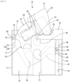
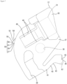
FIG. 1 is a side view depicting a state where, for a connector according to a first embodiment, a lever is disposed close to one end of a range of play at a temporary locking position with respect to a housing. -
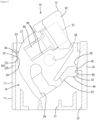
FIG. 2 is a plan view depicting a state where the lever is disposed close to one end of the range of play at the temporary locking position with respect to the housing. -
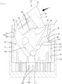
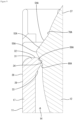
FIG. 3 is a broken plan view depicting a state where the lever is disposed close to another end of the range of play at the temporary locking position with respect to the housing, and a first locking surface and a second locking surface contact each other. -
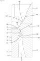
FIG. 4 is a broken plan view depicting a state where the lever has rotated to the other end of the range of play at the temporary locking position and a first locking portion has temporarily bent due to interference between a first apex portion and a second locking portion. -
FIG. 5 is an enlarged cross-sectional view of the first locking portion and the second locking portion in the state depicted inFIG. 3 . -
FIG. 6 is an enlarged cross-sectional view of the first locking portion and the second locking portion in the state depicted inFIG. 4 . -
FIG. 7 is a plan view of the lever. -
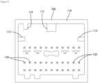
FIG. 8 is a front view of a mating housing. -
FIG. 9 is an enlarged cross-sectional view depicting a state where, for a connector according to a second embodiment, a first apex portion of a first locking portion and a second locking surface contact each other and are locked when a lever is at a temporary locking position. -
FIG. 10 is an enlarged cross-sectional view depicting a state where the first locking portion has temporarily bent from the state depicted inFIG. 9 . - Several embodiments of the present disclosure will first be listed and described in outline.
- A connector according to the present disclosure includes: a housing; and a lever that is supported by the housing and rotates from a temporary locking position to a main locking position to progressively fit the housing together with a mating housing, wherein one of the housing and the lever is provided with a first locking portion capable of flexible deformation and another of the housing and the lever is provided with a second locking portion, the first locking portion has a first apex portion and a first locking surface that is connected to the first apex portion, the second locking portion has a second locking surface that contacts the first locking portion and stops the lever at the temporary locking position, and the second locking surface has an inclined side which is disposed, in a state where the first locking portion has bent due to interference between the first apex portion and the second locking portion, so as to be inclined from the first apex portion toward the first locking surface.
- If the lever is inadvertently rotated within the range of play at the temporary locking position, the first locking portion becomes temporarily bent due to interference between the first apex portion and the second locking portion. However, since the second locking surface of the second locking portion has an inclined side, the second locking portion can receive the pressing force of the first apex portion and become displaced toward the side facing the first locking surface. Accordingly, the first locking portion and the second locking portion can be quickly returned to a lockable state, and bending of the first locking portion can be automatically eliminated.
- When performing a rotation operation of the lever, the operator can moderately experience that the bending of the first locking portion has been eliminated and the first locking portion and the second locking portion are in a locked state. This means that according to the above configuration, the locked state of the lever at the temporarily locked position can be appropriately released.
- Note that the expression "side" in the present specification refers to an edge on a plane in a cross-section that intersects the plane, and includes not only line segments but also curves. In a definition of a "side" as a line that joins apex points, the "apex points" may be on a curve (or curved surface).
- (2) The second locking portion preferably includes a second rising surface disposed on an opposite side to the second locking surface and a top portion disposed between the second rising surface and the inclined side.
- With this configuration, by changing the position of the top portion relative to the first locking portion, it is possible to easily adjust the angle of inclination and/or the formation range of the inclined side.
- (3) The second locking surface may include a locking side that intersects the inclined side with a second apex portion in between, and when the first locking portion is in a natural state at the temporary locking position, the locking side may be disposed so as to face and contact the first locking surface in parallel or at a shallower angle of inclination than the inclined side.
- With this configuration, even when the second locking surface has an inclined side, it is possible for the locking side to favorably contact the first locking surface. This means that it is possible to maintain or increase the locking force of the second locking portion on the first locking portion.
- (4) The housing may include a housing-side locking portion, the lever may include a lever-side locking portion that is locked to the housing-side locking portion at the temporary locking position, one of the housing-side locking portion and the lever-side locking portion may be capable of flexible deformation, a locking state of the housing-side locking portion and the lever-side locking portion may be released by a release portion of the mating housing, a gap, which allows the one of the housing-side locking portion and the lever-side locking portion to deform, may be formed between the lever-side locking portion and the housing-side locking portion, and the lever may be capable of rotating with respect to the housing within a range of the gap at the temporary locking position.
- With this configuration, it is easy to rotate the lever in a range of play at the temporary locking position including the gap described above, and easy to release the locked state of the lever at the temporary locking position. However, according to the present disclosure, even if the lever rotates within the range of play at the temporary locking position, the second locking surface does not stop on to the first apex portion, and the first locking portion and the second locking portion can return to the lockable state, which means that the locked state of the lever can be favorably ensured.
- Specific embodiments of the present disclosure are described below with reference to the drawings. It should be noted that the present invention is not limited to the examples described here, and is instead indicated by the claims and is intended to include all modifications within the meaning and scope of the claims and their equivalents.
- A
connector 10 includes ahousing 11 and alever 12 that is rotatably supported by thehousing 11. Thehousing 11 is fitted into amating housing 100. Thelever 12 rotates with respect to thehousing 11 from a temporary locking position to a main locking position, which progressively fits the twohousings housings FIGS. 1 and8 . The expression "width direction" is based on the left-right direction in the drawings aside fromFIG. 1 . - The
mating housing 100 is made of synthetic resin and, as depicted inFIGS. 4 and8 , has a squaretubular hood portion 110 that is open at the front. Thehood portion 110 has acam follower 111 in the form of a circular column that protrudes downward at a center in the width direction on an inner surface of an upper wall. At one end in the width direction of the inner surface of the upper wall, thehood portion 110 has a rib-shaped release portion 112 that protrudes downward and extends in the front-rear direction. At upper ends of inner surfaces of left and right side wall parts, thehood portion 110 has a pair ofguide portions 113 that project outward toward each other and extend in the front-rear direction. - A plurality of male
terminal fittings 120 are disposed so as to protrude on the inside of thehood portion 110. The maleterminal fittings 120 are each shaped like a tab and are arranged vertically and horizontally in a space below theguide portions 113 inside thehood portion 110. - The
housing 11 is made of synthetic resin and formed in the overall shape of a square block. As depicted inFIG. 4 , thehousing 11 is fitted inside thehood portion 110. As depicted inFIG. 1 , a plurality of femaleterminal fittings 20 are housed in the housing 11 (only one female terminal fitting 20 is illustrated inFIG. 1 ). Each female terminal fitting 20 is disposed at a position corresponding to a male terminal fitting 120. Each female terminal fitting 20 are connected to one end of anelectric wire 90. - The
housing 11 has, at upper ends (thereference numeral 17 side inFIG. 1 ) of left andright side walls FIG. 1 ) that extend in the front-rear direction and are open at the front. An operation that fits together the twohousings guide portions 113 into theguide channels 13. - As depicted in
FIGS. 3 and4 , at an upper end portion, thehousing 11 has ahousing portion 14 capable of housing thelever 12. Thehousing portion 14 is provided above a cavity region that houses the femaleterminal fittings 20. Thehousing portion 14 is delimited by the left andright side walls FIG. 2 ) of thehousing 11. As depicted inFIG. 2 , thehousing 11 has a lockingportion 19 that protrudes inside thehousing portion 14. Also on the inside of thehousing portion 14, as depicted inFIG. 2 , asupport shaft 62 that supports thelever 12 is disposed so as to protrude. - The
top wall 18 is formed in the shape of a flat plate. As depicted inFIG. 2 , in the center in the width direction, thetop wall 18 has anintroduction channel 21 that extends in the front-rear direction and is open at the front. Thesupport shaft 62 is disposed to a rear of thisintroduction channel 21. At one end in the width direction, thetop wall 18 also has areceiver channel 22 that extends in the front-rear direction and is open at the front. Thereceiver channel 22 has a narrower channel width than theintroduction channel 21, and is formed longer in the front-rear direction than theintroduction channel 21. Theintroduction channel 21 has a role of allowing thecam follower 111 to pass through and guiding thecam follower 111 to acam channel 39, described later, of thelever 12. Therelease portion 112 is inserted into thereceiver channel 22. - On one side in the width direction, the
top wall 18 has athick stopper portion 23 which protrudes along a rear end of thetop wall 18. In a center portion in the width direction of the rear end of thetop wall 18, thestopper portion 23 has arecess 24 that is recessed toward the front. On the other side in the width direction at the rear end, thetop wall 18 has a concave retractedportion 25 that is further recessed toward the front than thestopper portion 23. The lockingportion 19 can be visually confirmed from above through the inside of the retractedportion 25. - Out of the left and
right side walls side wall 16 on one side in the width direction has a housing-side locking portion 26 that protrudes into thehousing portion 14. The housing-side locking portion 26 can be visually confirmed from above through thereceiver channel 22. The housing-side locking portion 26 is formed in a trapezoidal shape. An inner surface, which is the protruding end of the housing-side locking portion 26, is linearly disposed along the front-rear direction. A front surface of the housing-side locking portion 26 is inclined so that the protruding end side projects toward the front. - As depicted in
FIG. 1 , out of the left andright side walls side wall 17 on the other side in the width direction has a pair of upper andlower slits 27 at an upper end portion that delimits theaccommodating portion 14. Both slits 27 extend in the front-rear direction and are open to the rear at a rear end side of the upper end portion of theside wall 17. - The
housing 11 has afirst locking portion 28 between theslits 27 at the upper end of theside wall 17. Thefirst locking portion 28 has anelastic portion 29, which extends from a front end between theslits 27 toward the rear in a cantilevered manner, and a lockingprotrusion 31 that protrudes from a rear end portion of theelastic portion 29 into thehousing portion 14. As depicted inFIGS. 3 to 5 , theelastic portion 29 constructs a part of theside wall 17 and is formed with a constant thickness. Theelastic portion 29 is capable of flexibly deforming inwardly and outwardly with a front end portion as a pivot. As depicted inFIGS. 3 and5 , in a natural state, theelastic portion 29 is disposed along the front-rear direction. - As depicted in
FIGS. 5 and6 , the lockingprotrusion 31 has afirst locking surface 32, a first risingsurface 33, and afirst apex portion 34 disposed between thefirst locking surface 32 and the first risingsurface 33. Thefirst locking surface 32 is connected via acurved portion 35 to an outer surface of the elastic portion 29 (which is the outer surface of the side wall 17), and is linearly disposed in a direction that intersects the outer surface of theelastic portion 29. As depicted inFIG. 5 , when theelastic portion 29 is in the natural state, thefirst locking surface 32 is disposed along the width direction. - The first rising
surface 33 is connected to an inner surface of the elastic portion 29 (which is the inner surface of the side wall 17), and is linearly inclined inward in the width direction with respect to the inner surface of theelastic portion 29 so as to extend deeper inside thehousing portion 14 toward the rear. A surface direction of the first risingsurface 33 and a surface direction of thefirst locking surface 32 intersect each other at an acute angle with thefirst apex portion 34 positioned in between. - The
first apex portion 34 is curved in an arc from thefirst locking surface 32 to the first risingsurface 33. Thefirst apex portion 34 intersects thefirst locking surface 32 and the first risingsurface 33, and is formed as a curved surface whose radius of curvature is smaller than that of thecurved portion 35. - As depicted in
FIG. 3 , acurved surface portion 36, which faces the rear out of thefirst apex portion 34, and thefirst locking surface 32 can be visually confirmed when thehousing 11 is viewed from the rear in a state where thelever 12 has not been assembled inside thehousing portion 14. - The
lever 12 is made of synthetic resin and as depicted inFIG. 7 has a levermain body 37 in the form of a single plate. The levermain body 37 has a bearingportion 38 that is open on a lower-side plate surface. When thelever 12 is assembled inside thehousing portion 14, thesupport shaft 62 fits into this bearingportion 38. Thelever 12 is rotatable about thesupport shaft 62 fitted into the bearingportion 38 between the temporary locking position and the main locking position. - The lever
main body 37 has thecam channel 39 that is open on an upper-side plate surface. Thecam channel 39 is also open at an outer peripheral edge of the levermain body 37. As depicted inFIG. 4 , when thelever 12 is at the temporary locking position, thecam follower 111 of themating housing 100 enters the entrance of thecam channel 39. As thelever 12 rotates from the temporary locking position to the main locking position, thecam follower 111 maintains sliding contact with a channel surface of thecam channel 39, which pulls themating housing 100 toward thehousing 11 and progressively fits the twohousings lever 12 has reached the main locking position, thecam follower 111 becomes disposed at the inner end of thecam channel 39 and the twohousings housings terminal fittings 20 and the respective maleterminal fittings 120 are electrically connected. - The lever
main body 37 has a lever-side locking portion 42 that protrudes rearward as a cantilever from abase end portion 41 on an outer peripheral edge of the levermain body 37 near the entrance to thecam channel 39. As depicted inFIG. 7 , the lever-side locking portion 42 has an extendingportion 43 disposed linearly from thebase end portion 41, and a lockingmain body 44 that protrudes diagonally outward with respect to the extendingportion 43. The extendingportion 43 is capable of flexibly deforming inwardly and outwardly in the width direction with thebase end portion 41 as a pivot. - At a corner on the rear end, the locking
main body 44 has a lockingrecess 45 in the form of an L-shaped notch. As depicted inFIG. 3 , at the temporary locking position, the lockingrecess 45 faces a front end angledregion 46 formed from an inner surface to a front surface of the housing-side locking portion 26. At a corner on a front end, the lockingmain body 44 has arelief recess 47 shaped so that a lower surface side is diagonally cut out. - The lever
main body 37 has a lockingarm 48 on an opposite side in the width direction to the side with the bearingportion 38, thecam channel 39, and the lever-side locking portion 42. The lockingarm 48 is disposed so as to be capable of flexible deformation between a pair ofcutouts 49 formed in the levermain body 37. At the main locking position, the lockingarm 48 becomes locked to the locking portion 19 (seeFIG. 2 ). The twohousings arm 48 and the lockingportion 19. At the main locking position, a front portion of the lockingarm 48 is disposed inside the retractedportion 25. By doing so, interference between the lockingarm 48 and thetop wall 18 is avoided. - At a rear end portion (that is, an end portion located at the rear at the main locking position), the locking
arm 48 has alock releasing portion 51 which extends in the width direction. The locking of the lockingarm 48 and the lockingportion 19 is released by pressing thislock releasing portion 51. By rotating thelever 12 toward the temporary locking position after the locking of the lockingarm 48 and the lockingportion 19 has been released, it is possible to return thelever 12 from the main locking position to the temporary locking position. - The
lever 12 has a bridge-shaped erectedpart 52 at a rear end of the levermain body 37. The erectedpart 52 covers the outside of thelock releasing portion 51 and prevents unintended releasing operations of thelock releasing portion 51. As depicted inFIG. 2 , an inner edge portion of the erectedpart 52 is formed in a protruding shape that fits into therecess 24 of thestopper portion 23 at the temporary locking position. - The
lever 12 has asecond locking portion 53 that protrudes on an outer peripheral edge of thelever body 37. Thesecond locking portion 53 is disposed at a position close to the front end portion of the lockingarm 48. Thesecond locking portion 53 is formed in a claw shape. Thesecond locking portion 53 is formed with a constant thickness within a range of the thickness of the levermain body 37. As depicted inFIG. 7 , thesecond locking portion 53 has a second risingsurface 54, atop portion 55, and asecond locking surface 56. - The
top portion 55 is formed on a front end in the protruding direction of thesecond locking portion 53. Thetop portion 55 is a part where the second risingsurface 54 and thesecond locking surface 56 intersect, and is configured as an obtuse-angled apex part between the second risingsurface 54 and thesecond locking surface 56. - The second rising
surface 54 is connected to thetop portion 55 on the opposite side (or rear side) to the side in which thelever 12 rotates toward the main locking position. As depicted inFIG. 6 , the second risingsurface 54 is linearly disposed at a constant inclination angle from a connectingposition 70 on the outer peripheral edge of the levermain body 37 to thetop portion 55. The second risingsurface 54 is an inclined surface with a gentle inclination angle with respect to the tangential direction at the connectingposition 70 on the outer peripheral edge of the levermain body 37. - The
second locking surface 56 is connected to thetop portion 55 on the side (or front side) in which thelever 12 rotates toward the main locking position. As depicted inFIG. 6 , thesecond locking surface 56 has acurved side 57 that connects to a connectingposition 80 on the outer peripheral edge of the levermain body 37. Thecurved side 57 is formed as a U-shaped recess when viewed from the front. - Between the
curved side 57 and thetop portion 55, thesecond locking surface 56 has aninclined side 58 and a lockingside 59 with respectively different inclination angles with respect to a tangential direction at the connectingposition 80 on the outer peripheral edge of thelever body 37. Thesecond locking surface 56 has asecond apex portion 61 between theinclined side 58 and the lockingside 59. - The locking
side 59 is linearly arranged at a constant inclination angle from thecurved side 57 to theinclined side 58. The lockingside 59 forms a right angle or an angle close to a right angle with respect to the tangential direction at the connecting position on the outer peripheral edge of thelever body 37. Theinclined side 58 is linearly disposed at a constant inclination angle from thesecond apex portion 61 to thetop portion 55. Theinclined side 58 is an inclined surface with a gentle inclination angle of 45 degrees or lower with respect to the tangential direction at the connecting position on the outer peripheral edge of the levermain body 37. - The
inclined side 58 is disposed between thetop portion 55 and thesecond apex portion 61, and is connected at an obtuse angle to the second risingsurface 54 via thetop portion 55. Theinclined side 58 connects at an obtuse angle to the lockingside 59 via thesecond apex portion 61. When thelever 12 is at the temporary locking position, theinclined side 58 is disposed so as to be inclined to one side in the width direction toward the front. - The length (that is, the length in the inclined direction) of the
inclined side 58 is smaller than the length of the lockingside 59. The length of the second risingsurface 54 is greater than the sum of the length of theinclined side 58 and the length of the lockingside 59. - The
lever 12 may rotate with respect to thehousing 11 within a range of play at the temporary locking position. When thelever 12 is at one end of the range of play at the temporary locking position, as depicted inFIG. 2 , the inner edge portion of the erectedpart 52 is disposed to fit into therecess 24 of thestopper portion 23 so as to be lockable. By doing so, thelever 12 is restricted from rotating from the temporary locking position in the opposite direction to the main locking position. At this time, the lockingrecess 45 of the lever-side locking portion 42 is disposed away from the front end angledregion 46 of the housing-side locking portion 26. Thesecond locking surface 56 of thesecond locking portion 53 is also disposed away from thefirst locking surface 32 of thefirst locking portion 28. - On the other hand, when the
lever 12 is at the other end of the range of play at the temporary locking position, as depicted inFIG. 3 , the lockingrecess 45 of the lever-side locking portion 42 is disposed so as to be capable of fitting together with and locking on the front end angledregion 46 of the housing-side locking portion 26. Also, as depicted inFIG. 5 , the lockingside 59 of thesecond locking surface 56 is disposed so as to face and be capable of locking on thefirst locking surface 32. In more detail, the lockingside 59 of thesecond locking surface 56 is disposed so as to contact a front end region (that is, a first apex portion 34-side region) of thefirst locking surface 32 at a gentle angle of inclination or in parallel. By doing so, rotation of thelever 12 from the temporary locking position toward the main locking position is restricted. - Note that as depicted in
FIG. 2 , when thelever 12 is at one end in the range of play at the temporary locking position, agap 60 that allows flexible deformation of the extendingportion 43 of the lever-side locking portion 42 is formed between the lockingrecess 45 of the lever-side locking portion 42 and the front end angledregion 46 of the housing-side locking portion 26. - Also, when the
lever 12 is at the temporary locking position, the entrance of thecam channel 39 communicates with theintroduction channel 21. In this state, as depicted inFIG. 4 , thehousing 11 is shallowly fit inside themating housing 100. When that happens, thecam follower 111 comes disposed at the entrance of theintroduction channel 21 and thecam channel 39. - When the
housing 11 has been shallowly fitted into themating housing 100, therelease portion 112 is inserted into thereceiver channel 22. A front end of therelease portion 112 abuts the lockingbody 44 of the lever-side locking portion 42 and the lockingbody 44 becomes pressed by therelease portion 112, causing flexible deformation of the extendingportion 43. Bending of the extendingportion 43 is allowed within the range of play (that is, the gap 60) at the temporary locking position. When flexible deformation of the extendingportion 43 occurs, interference between the front end angledregion 46 of the housingside locking portion 26 and the lockingmain body 44 is avoided by therelief recess 47. - Next, the operator presses the erected
part 52 or the like to rotate thelever 12 from the temporary locking position to the main locking position. At the start of rotation of thelever 12, thesecond locking portion 53 presses thefirst locking portion 28 causing flexible deformation of theelastic portion 29, thesecond apex portion 61 passes over thefirst apex portion 34 and then the bending of theelastic portion 29 is eliminated. As theelastic portion 29 elastically recovers, theelastic portion 29 will hit the outer peripheral edge of thelever 12, causing a knocking sound. By hearing this knocking sound and/or feeling a change in the operating force due to the elimination of the bending of theelastic portion 29, it is possible for the operator to recognize that the locked state of thelever 12 at the temporary locking position has been released. - After this, the
lever 12 reaches the main locking position, where the lockingarm 48 locks onto the lockingportion 19 so that the twohousings - However, before the two
housings part 52 so that an external force F (seeFIG. 4 ) acts on thelever 12 at the temporary locking position in a direction in which thelever 12 rotates toward the main locking position. When such an external force F acts, there are concerns that thesecond locking portion 53 will press the lockingprotrusion 31 of thefirst locking portion 28 at the other end of the range of play, resulting in unintended flexible deformation of theelastic portion 29. When this happens, if bending of theelastic portion 29 is not eliminated and theelastic portion 29 remains flexibly deformed, at the start of a rotation operation of thelever 12, the operator will not be able to obtain the sense of release described above and recognize that the locked state of thelever 12 has been released. - However, the first embodiment ensures that bending of the
elastic portion 29 will have been eliminated when the operator performs a rotation operation of thelever 12. In more detail, if flexible deformation of theelastic portion 29 occurs before the twohousings FIG. 6 , theinclined side 58 of thesecond locking surface 56 will contact thefirst apex portion 34 of the lockingprojection 31. At this time, theinclined side 58 becomes disposed so as to be inclined and approach thecurved surface portion 36 and thefirst locking surface 32 side from thefirst apex portion 34 in the front-rear direction. - In this state, the
elastic portion 29 will try to elastically recover from the bent state in a recovery direction where the bending is eliminated. Thefirst apex portion 34 will press theinclined side 58 of thesecond locking surface 56 in the recovery direction of theelastic portion 29. As depicted inFIG. 6 , a pressing force P will act on thesecond locking portion 53 in a direction perpendicular to the surface direction of theinclined side 58, and a rearward component force P1 will also act as a partial force (or "component") of the pressing force P. As a result, thesecond locking portion 53 becomes rearwardly displaced with respect to thefirst apex portion 34 by the component force P1. Meanwhile, thefirst apex portion 34 slides on theinclined side 58 and becomes displaced toward thesecond apex portion 61. As this happens, bending of theelastic portion 29 will become automatically eliminated. When thefirst apex portion 34 has passed over thesecond apex portion 61, the bending of theelastic portion 29 is instantly eliminated, and theelastic portion 29 returns to the natural state. When theelastic portion 29 has returned to the natural state, as depicted inFIG. 5 , thefirst locking surface 32 will face the lockingside 59 of thesecond locking surface 56 so as to be lockable. - In the case of the first embodiment, the
first apex portion 34 is set so as to contact theinclined side 58 even when theelastic portion 29 has maximally bent within the range of play at the temporary locking position. This means that no matter how theelastic portion 29 bends within the range of play for thelever 12 at the temporary locking position, thefirst locking portion 28 and thesecond locking portion 53 can be kept in a lockable state by theinclined side 58. - As described above, according to the first embodiment, since the
inclined side 58 of thesecond locking surface 56 is disposed so as to be inclined from thefirst apex portion 34 toward thefirst locking surface 32, even if thelever 12 is inadvertently rotated within the range of play at the temporary locking position and theelastic portion 29 of thefirst locking portion 28 becomes temporarily bent, thesecond locking surface 56 will become displaced toward a side facing thefirst locking surface 32, which makes it possible to return to a state where thefirst locking portion 28 and thesecond locking portion 53 are lockable. As a result, the bending of theelastic portion 29 can be automatically eliminated. This ensures that when the operator starts a rotation operation of thelever 12, thefirst locking surface 32 and thesecond locking surface 56 will face each other in a lockable state. As a result, the operator can moderately experience the state of the bending of thefirst locking portion 28 being eliminated, and can appropriately proceed with a rotation operation of thelever 12. - In particular, in the first embodiment, the
gap 60, which allows the lever-side locking portion 42 to bend when thelever 12 is at the temporary locking position, is formed between the lever-side locking portion 42 and the housing-side locking portion 26, which means the range of play including thegap 60 can be large. Since it is easy for thelever 12 to rotate within the range of play at the temporary locking position, there is a large merit to using the above configuration which enables thefirst locking portion 28 and thesecond locking portion 53 to return to the lockable state. - Also, since the
second locking portion 53 has thetop portion 55 between theinclined side 58 and the second risingsurface 54, it is possible to easily adjust the inclination angle and the formation range of theinclined side 58 by changing the relative position of thetop portion 55 with respect to thefirst locking portion 28. - Additionally, the
second locking surface 56 has aninclined side 58 and a lockingside 59 with thesecond apex portion 61 in between, and at the temporary locking position, the lockingside 59 is capable of facing and contacting thefirst locking surface 32 in parallel or at a gentler angle of inclination than theinclined side 58. This makes it possible to favorably ensure that thesecond locking portion 53 exerts a locking force on thefirst locking portion 28. - Next, a second embodiment of the present disclosure will be described with reference to
FIGS. 9 and10 . In this second embodiment, the shape of asecond locking portion 53A differs to the first embodiment described above. Other elements are the same as in the first embodiment. In the following description, identical or corresponding structures as those in the first embodiment have been assigned the same reference numerals and redundant description is omitted. - The
second locking portion 53A is triangular in cross section and protrudes on the outer peripheral edge of the levermain body 37. Thesecond locking portion 53A has atop portion 55A at a front end in the protruding direction, a second risingsurface 54A located to the rear of thetop portion 55A, and asecond locking surface 56A located to the front of thetop portion 55A. - The
top portion 55A is a part where the second risingsurface 54A and thesecond locking surface 56A intersect, and is configured as an obtuse-angled apex part between the second risingsurface 54A and thesecond locking surface 56A. - The second rising
surface 54A is linearly disposed at a constant inclination angle from a connectingposition 70A on the outer peripheral edge of the levermain body 37 to thetop portion 55A. The second risingsurface 54A is an inclined surface with a gentle angle of inclination with respect to the tangential direction at the connectingposition 70A on the outer peripheral edge of the levermain body 37. The length (that is, the length in the inclined direction) of the second risingsurface 54A is shorter than the length of the second risingsurface 54A in the first embodiment. - The
second locking surface 56A is linearly disposed at a constant inclination angle from a connectingposition 80A on the outer peripheral edge of the levermain body 37 to thetop portion 55A. Thesecond locking surface 56A as a whole is configured as an inclined side 58A. Thesecond locking surface 56A does not have a part corresponding to thesecond apex portion 61 in the first embodiment. Thesecond locking surface 56A as a whole is an inclined surface with a gentle angle of inclination of 45 degrees (n / 4) or below with respect to the tangential direction at the connectingposition 80A on the outer peripheral edge of the levermain body 37. The angle of inclination of thesecond locking surface 56A is the same as or close to the angle of inclination of thefirst locking surface 32. The angle of inclination of thesecond locking surface 56A is larger than the angle of inclination of the inclined side 58A in the first embodiment and smaller than the angle of inclination of the lockingside 59 in the first embodiment. The length of thesecond locking surface 56A is shorter than the length of the second risingsurface 54A. - If inadvertent flexible deformation of the
elastic portion 29 occurs when thelever 12 is present at the temporary locking position before the twohousings first apex portion 34 will come into contact with thesecond locking surface 56A. When theelastic portion 29 has flexibly deformed by a maximum amount, thefirst apex portion 34 will contact a rear portion of thesecond locking surface 56A. The pressing force PA caused by the bending of theelastic portion 29 and the component force PA1 as a partial force (or "component") of the pressing force PA will act on thesecond locking portion 53A. Thesecond locking portion 53A becomes rearwardly displaced with respect to thefirst apex portion 34 by the component force PA1. Meanwhile, thefirst apex portion 34 will become displaced to the front on the inclined side 58A. By doing so, the bending of theelastic portion 29 becomes automatically eliminated. When theelastic portion 29 has returned to the natural state, thefirst apex portion 34 is displaced toward a front portion of thesecond locking surface 56A. In this second embodiment, thefirst apex portion 34 is a part that faces and is capable of locking on thesecond locking surface 56A at the temporary locking position. Thesecond locking surface 56A is the inclined side 58A and is also a part that faces and is capable of locking on thefirst apex portion 34. This means that according to the second embodiment, a state in which thefirst locking portion 28 and thesecond locking portion 53A are locked at the temporary locking position is appropriately produced. - It should be understood that the embodiments disclosed herein are exemplary in all respects and not restrictive.
- Although the first locking portion that is capable of flexible deformation is provided on the housing and the second locking portion that is not capable of flexible deformation is provided on the lever in the first and second embodiments described above, as another embodiment, it is also possible to provide a first locking portion that is capable of flexible deformation on the lever and provide a second locking portion that is not capable of flexible deformation on the housing.
- Although the lever-side locking portion is capable of flexible deformation and the housing-side locking portion is rigid and does not flexibly deform in the first and second embodiments described above, as another embodiment, it is also possible to use a configuration where the lever-side locking portion is rigid and does not flexibly deform and the housing-side locking portion is capable of flexible deformation.
- Although the lever at the temporary locking position is primarily held by the housing-side locking portion and the lever-side locking portion and is secondarily held by the first locking portion and the second locking portion in the first and second embodiments described above, as another embodiment, it is also possible to use a configuration where the housing-side locking portion and the lever-side locking portion are omitted from the connector, and the lever at the temporary locking position is held by only the first locking portion and the second locking portion.
- In the first and second embodiments described above, the first apex portion has a rounded shape. However, as another embodiment, the first apex portion may be formed in a sharply pointed shape.
- In the first embodiment described above, the second apex portion is formed in a sharply pointed shape. However, as another embodiment, the second apex portion may have a rounded shape.
- In the first embodiment described above, the second locking surface is composed of an inclined side, a locking side, a second apex portion and a curved side. However, as another embodiment, the second locking surface may be composed of an inclined side and a second apex portion without having a curved side.
- In the first embodiment described above, the locking side is disposed so as to contact the first locking surface at a gentle inclination angle at the temporary locking position. However, as another embodiment, the locking side may be disposed so as to contact the first locking surface in parallel at the temporarily locking position.
- In the embodiments described above, the lever is composed of a lever main body in the form of a single plate, but as another embodiment, the lever may be a gate-shaped lever where a pair of lever main bodies are connected by a connecting portion.
-
- 10
- Connector
- 11
- Housing
- 12
- Lever
- 13
- Guide channel
- 14
- Housing portion
- 16, 17
- Left and right side walls
- 18
- Top wall
- 19
- Locking portion
- 20
- Female terminal fitting
- 21
- Introduction channel
- 22
- Receiver channel
- 23
- Stopper portion
- 24
- Recess
- 25
- Retracted part
- 26
- Housing-side locking portion
- 27
- Slit
- 28
- First locking portion
- 29
- Elastic portion
- 31
- Locking protrusion
- 32
- First locking surface
- 33
- First rising surface
- 34
- First apex portion
- 35
- Curved portion
- 36
- Curved surface portion
- 37
- Lever main body
- 38
- Bearing portion
- 39
- Cam channel
- 41
- Base end portion
- 42
- Lever-side locking portion
- 43
- Extending portion
- 44
- Locking main body
- 45
- Locking recess
- 46
- Front end angled region
- 47
- Relief recess
- 48
- Locking arm
- 49
- Cut out
- 51
- Lock releasing portion
- 52
- Erected part
- 53, 53A
- Second locking portion
- 54, 54A
- Second rising surface
- 55, 55A
- Top portion
- 56, 56A
- Second locking surface
- 57
- Curved side
- 58, 58A
- Inclined side
- 59
- Locking side
- 60
- Gap
- 61
- Second apex portion
- 62
- Support shaft
- 70, 70A, 80, 80A
- Connecting position
- 90
- Wire
- 100
- Mating housing
- 110
- Hood portion
- 111
- Cam follower
- 112
- Release portion
- 113
- Guide portion
- 120
- Male terminal fittings
- F
- External force
- P, PA
- Pressing force
- P1, PA1
- Component force
Claims (4)
- A connector comprising:a housing; anda lever that is supported by the housing and rotates from a temporary locking position to a main locking position to progressively fit the housing together with a mating housing,wherein one of the housing and the lever is provided with a first locking portion capable of flexible deformation and another of the housing and the lever is provided with a second locking portion,the first locking portion has a first apex portion and a first locking surface that is connected to the first apex portion,the second locking portion has a second locking surface that contacts the first locking portion and stops the lever at the temporary locking position, andthe second locking surface has an inclined side which is disposed, in a state where the first locking portion has bent due to interference between the first apex portion and the second locking portion, so as to be inclined from the first apex portion toward the first locking surface.
- The connector according to claim 1,
wherein the second locking portion includes a second rising surface disposed on an opposite side to the second locking surface and a top portion disposed between the second rising surface and the inclined side. - The connector according to claim 1 or 2,wherein the second locking surface includes a locking side that intersects the inclined side with a second apex portion in between, andwhen the first locking portion is in a natural state at the temporary locking position, the locking side is disposed so as to face and contact the first locking surface in parallel or at a shallower angle of inclination than the inclined side.
- The connector according to any one of claims 1 to 3,wherein the housing includes a housing-side locking portion,the lever includes a lever-side locking portion that is locked to the housing-side locking portion at the temporary locking position,one of the housing-side locking portion and the lever-side locking portion is capable of flexible deformation,a locking state of the housing-side locking portion and the lever-side locking portion is released by a release portion of the mating housing,a gap, which allows the one of the housing-side locking portion and the lever-side locking portion to deform, is formed between the lever-side locking portion and the housing-side locking portion, andthe lever is capable of rotating with respect to the housing within a range of the gap at the temporary locking position.
Applications Claiming Priority (2)
| Application Number | Priority Date | Filing Date | Title |
|---|---|---|---|
| JP2020142474A JP7437614B2 (en) | 2020-08-26 | 2020-08-26 | connector |
| PCT/JP2021/028206 WO2022044688A1 (en) | 2020-08-26 | 2021-07-29 | Connector |
Publications (2)
| Publication Number | Publication Date |
|---|---|
| EP4207510A1 true EP4207510A1 (en) | 2023-07-05 |
| EP4207510A4 EP4207510A4 (en) | 2024-02-14 |
Family
ID=80353075
Family Applications (1)
| Application Number | Title | Priority Date | Filing Date |
|---|---|---|---|
| EP21861116.8A Pending EP4207510A4 (en) | 2020-08-26 | 2021-07-29 | Connector |
Country Status (5)
| Country | Link |
|---|---|
| US (1) | US20230299539A1 (en) |
| EP (1) | EP4207510A4 (en) |
| JP (1) | JP7437614B2 (en) |
| CN (1) | CN116057787A (en) |
| WO (1) | WO2022044688A1 (en) |
Family Cites Families (7)
| Publication number | Priority date | Publication date | Assignee | Title |
|---|---|---|---|---|
| JP3758525B2 (en) | 2001-05-24 | 2006-03-22 | 住友電装株式会社 | Lever type connector |
| JP4577209B2 (en) * | 2005-12-26 | 2010-11-10 | 住友電装株式会社 | connector |
| JP2010287427A (en) | 2009-06-11 | 2010-12-24 | Nissan Motor Co Ltd | Power supply circuit connection device |
| WO2014192800A1 (en) | 2013-05-30 | 2014-12-04 | 矢崎総業株式会社 | Connector |
| JP6252068B2 (en) | 2013-09-24 | 2017-12-27 | 矢崎総業株式会社 | Lever fitting type connector |
| JP6246646B2 (en) * | 2014-03-31 | 2017-12-13 | タイコエレクトロニクスジャパン合同会社 | Lever type connector |
| JP6332074B2 (en) * | 2015-02-16 | 2018-05-30 | 住友電装株式会社 | Lever type connector |
-
2020
- 2020-08-26 JP JP2020142474A patent/JP7437614B2/en active Active
-
2021
- 2021-07-29 CN CN202180050931.0A patent/CN116057787A/en active Pending
- 2021-07-29 WO PCT/JP2021/028206 patent/WO2022044688A1/en unknown
- 2021-07-29 EP EP21861116.8A patent/EP4207510A4/en active Pending
- 2021-07-29 US US18/021,501 patent/US20230299539A1/en active Pending
Also Published As
| Publication number | Publication date |
|---|---|
| CN116057787A (en) | 2023-05-02 |
| JP2022038143A (en) | 2022-03-10 |
| EP4207510A4 (en) | 2024-02-14 |
| US20230299539A1 (en) | 2023-09-21 |
| JP7437614B2 (en) | 2024-02-26 |
| WO2022044688A1 (en) | 2022-03-03 |
Similar Documents
| Publication | Publication Date | Title |
|---|---|---|
| JP4457927B2 (en) | connector | |
| US7448888B2 (en) | Connector and a connector assembly | |
| US8662906B2 (en) | Plug-and-socket connector with a blocking element | |
| JP4497038B2 (en) | Lever type connector | |
| EP2284960A1 (en) | Lever-type connector | |
| US20060270258A1 (en) | Connector fitting structure | |
| JP2006344473A (en) | Lever type connector | |
| JP6492030B2 (en) | connector | |
| JP4066951B2 (en) | Lever type connector | |
| JP2008533684A (en) | Lever fitting type connector assembly having connector position assurance device | |
| JP5945964B2 (en) | connector | |
| JP6394981B2 (en) | Lever type connector | |
| JP6492029B2 (en) | connector | |
| JP3275290B2 (en) | Lever connector | |
| JP2006505104A (en) | Flexible flat cable connector | |
| JP2022039032A (en) | connector | |
| EP4207510A1 (en) | Connector | |
| JP2015046245A (en) | Relay terminal, and relay connector | |
| US6953372B2 (en) | Connector with press-in terminal fittings and recessed bulges surrounding the terminal fittings | |
| JP4655997B2 (en) | connector | |
| JP4254482B2 (en) | connector | |
| JP7275274B2 (en) | connector | |
| EP1916746A2 (en) | A connector | |
| CN107785730B (en) | Electrical connector for flat conductor | |
| JP4093583B2 (en) | Electrical connector for flat cable |
Legal Events
| Date | Code | Title | Description |
|---|---|---|---|
| STAA | Information on the status of an ep patent application or granted ep patent |
Free format text: STATUS: THE INTERNATIONAL PUBLICATION HAS BEEN MADE |
|
| PUAI | Public reference made under article 153(3) epc to a published international application that has entered the european phase |
Free format text: ORIGINAL CODE: 0009012 |
|
| STAA | Information on the status of an ep patent application or granted ep patent |
Free format text: STATUS: REQUEST FOR EXAMINATION WAS MADE |
|
| 17P | Request for examination filed |
Effective date: 20230220 |
|
| AK | Designated contracting states |
Kind code of ref document: A1 Designated state(s): AL AT BE BG CH CY CZ DE DK EE ES FI FR GB GR HR HU IE IS IT LI LT LU LV MC MK MT NL NO PL PT RO RS SE SI SK SM TR |
|
| DAV | Request for validation of the european patent (deleted) | ||
| DAX | Request for extension of the european patent (deleted) | ||
| REG | Reference to a national code |
Ref country code: DE Ref legal event code: R079 Free format text: PREVIOUS MAIN CLASS: H01R0013631000 Ipc: H01R0013629000 |
|
| A4 | Supplementary search report drawn up and despatched |
Effective date: 20240117 |
|
| RIC1 | Information provided on ipc code assigned before grant |
Ipc: H01R 13/629 20060101AFI20240111BHEP |