WO2022044667A1 - 非水電解液二次電池の正極の処理方法 - Google Patents
非水電解液二次電池の正極の処理方法 Download PDFInfo
- Publication number
- WO2022044667A1 WO2022044667A1 PCT/JP2021/027851 JP2021027851W WO2022044667A1 WO 2022044667 A1 WO2022044667 A1 WO 2022044667A1 JP 2021027851 W JP2021027851 W JP 2021027851W WO 2022044667 A1 WO2022044667 A1 WO 2022044667A1
- Authority
- WO
- WIPO (PCT)
- Prior art keywords
- positive electrode
- secondary battery
- foil
- electrolytic solution
- heating
- Prior art date
- Legal status (The legal status is an assumption and is not a legal conclusion. Google has not performed a legal analysis and makes no representation as to the accuracy of the status listed.)
- Ceased
Links
Images

Classifications
-
- H—ELECTRICITY
- H01—ELECTRIC ELEMENTS
- H01M—PROCESSES OR MEANS, e.g. BATTERIES, FOR THE DIRECT CONVERSION OF CHEMICAL ENERGY INTO ELECTRICAL ENERGY
- H01M10/00—Secondary cells; Manufacture thereof
- H01M10/54—Reclaiming serviceable parts of waste accumulators
-
- C—CHEMISTRY; METALLURGY
- C22—METALLURGY; FERROUS OR NON-FERROUS ALLOYS; TREATMENT OF ALLOYS OR NON-FERROUS METALS
- C22B—PRODUCTION AND REFINING OF METALS; PRETREATMENT OF RAW MATERIALS
- C22B21/00—Obtaining aluminium
- C22B21/0038—Obtaining aluminium by other processes
- C22B21/0069—Obtaining aluminium by other processes from scrap, skimmings or any secondary source aluminium, e.g. recovery of alloy constituents
-
- C—CHEMISTRY; METALLURGY
- C22—METALLURGY; FERROUS OR NON-FERROUS ALLOYS; TREATMENT OF ALLOYS OR NON-FERROUS METALS
- C22B—PRODUCTION AND REFINING OF METALS; PRETREATMENT OF RAW MATERIALS
- C22B21/00—Obtaining aluminium
- C22B21/0084—Obtaining aluminium melting and handling molten aluminium
- C22B21/0092—Remelting scrap, skimmings or any secondary source aluminium
-
- C—CHEMISTRY; METALLURGY
- C22—METALLURGY; FERROUS OR NON-FERROUS ALLOYS; TREATMENT OF ALLOYS OR NON-FERROUS METALS
- C22B—PRODUCTION AND REFINING OF METALS; PRETREATMENT OF RAW MATERIALS
- C22B21/00—Obtaining aluminium
- C22B21/02—Obtaining aluminium with reducing
-
- C—CHEMISTRY; METALLURGY
- C22—METALLURGY; FERROUS OR NON-FERROUS ALLOYS; TREATMENT OF ALLOYS OR NON-FERROUS METALS
- C22B—PRODUCTION AND REFINING OF METALS; PRETREATMENT OF RAW MATERIALS
- C22B5/00—General methods of reducing to metals
- C22B5/02—Dry methods smelting of sulfides or formation of mattes
-
- C—CHEMISTRY; METALLURGY
- C22—METALLURGY; FERROUS OR NON-FERROUS ALLOYS; TREATMENT OF ALLOYS OR NON-FERROUS METALS
- C22B—PRODUCTION AND REFINING OF METALS; PRETREATMENT OF RAW MATERIALS
- C22B7/00—Working up raw materials other than ores, e.g. scrap, to produce non-ferrous metals and compounds thereof; Methods of a general interest or applied to the winning of more than two metals
- C22B7/001—Dry processes
-
- Y—GENERAL TAGGING OF NEW TECHNOLOGICAL DEVELOPMENTS; GENERAL TAGGING OF CROSS-SECTIONAL TECHNOLOGIES SPANNING OVER SEVERAL SECTIONS OF THE IPC; TECHNICAL SUBJECTS COVERED BY FORMER USPC CROSS-REFERENCE ART COLLECTIONS [XRACs] AND DIGESTS
- Y02—TECHNOLOGIES OR APPLICATIONS FOR MITIGATION OR ADAPTATION AGAINST CLIMATE CHANGE
- Y02P—CLIMATE CHANGE MITIGATION TECHNOLOGIES IN THE PRODUCTION OR PROCESSING OF GOODS
- Y02P10/00—Technologies related to metal processing
- Y02P10/20—Recycling
-
- Y—GENERAL TAGGING OF NEW TECHNOLOGICAL DEVELOPMENTS; GENERAL TAGGING OF CROSS-SECTIONAL TECHNOLOGIES SPANNING OVER SEVERAL SECTIONS OF THE IPC; TECHNICAL SUBJECTS COVERED BY FORMER USPC CROSS-REFERENCE ART COLLECTIONS [XRACs] AND DIGESTS
- Y02—TECHNOLOGIES OR APPLICATIONS FOR MITIGATION OR ADAPTATION AGAINST CLIMATE CHANGE
- Y02W—CLIMATE CHANGE MITIGATION TECHNOLOGIES RELATED TO WASTEWATER TREATMENT OR WASTE MANAGEMENT
- Y02W30/00—Technologies for solid waste management
- Y02W30/50—Reuse, recycling or recovery technologies
- Y02W30/84—Recycling of batteries or fuel cells
Definitions
- the present invention relates to a method for treating a non-aqueous electrolyte secondary battery.
- Non-aqueous electrolyte secondary batteries such as lithium-ion secondary batteries are used as a power source to be mounted on hybrid vehicles and electric vehicles.
- the electrodes of the non-aqueous electrolyte secondary battery, especially the positive electrode contain valuable resources such as nickel (Ni) and cobalt (Co).
- Ni and Co cobalt
- Patent Document 1 describes, as a method for recovering cobalt from a secondary battery waste product, a method for recovering cobalt by roasting the battery waste product at 600 ° C. or higher, cutting, sieving, magnetic separation, and acid dissolving. Has been done.
- Patent Document 2 describes a method of recovering valuable resources such as Ni and Co by mixing a reducing agent with a recovered product containing Ni and Co obtained from a secondary battery and heating the recovered product.
- the recovery method described in Patent Document 1 requires steps such as magnetic separation and acid dissolution after roasting, so that there is a problem that the recycling cost is high.
- the recovery method described in Patent Document 2 requires a step of mixing the reducing agent, and has a problem that the mixing time and cost of the reducing agent are high. Further, in order to increase the reaction efficiency, a step of forming a mixture of the recovered product and the reducing agent into a briquette shape is also required.
- thermoit method As one of the methods for recovering a metal containing valuable resources from a positive electrode active material composed of a metal composite oxide.
- the thermite method generally uses a raw material in a powder state, and in order to use the positive electrode metal leaf in the thermite method, a step of pulverizing the metal leaf is required.
- the thermite reaction is to be carried out as it is without crushing the positive electrode metal foil, external heating at a high temperature using a high frequency induction melting furnace or the like is required, which is a barrier to cost reduction.
- an object of the present invention is to provide a method for treating the positive electrode of a non-aqueous electrolytic solution secondary battery, which can promote the reduction reaction of the positive electrode at low cost.
- the method for treating a positive electrode of a non-aqueous electrolytic solution secondary battery according to the present invention is a method for treating a positive electrode of a non-aqueous electrolytic solution secondary battery including a positive electrode having a foil containing Al and an active material as a metal composite oxide.
- the reduction reaction of the positive electrode active material can be promoted at low cost by performing the heat treatment on the positive electrode.
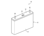
- FIG. 1 is a perspective view of the non-aqueous electrolyte secondary battery 10 used in the method for treating the non-aqueous electrolyte secondary battery according to the present embodiment.
- the non-aqueous electrolyte secondary battery 10 is a used lithium ion secondary battery used as a power source for automobiles such as electric vehicles and hybrid vehicles.
- the non-aqueous electrolyte secondary battery 10 is a lithium ion secondary battery will be described as an example, but the non-aqueous electrolyte secondary battery 10 is not limited to the lithium ion secondary battery, and magnesium.
- the non-aqueous electrolytic solution secondary battery 10 may be an unused lithium ion secondary battery or the like whose defect has been confirmed after production. Further, it may be process scraps or the like generated in the manufacturing process.
- the non-aqueous electrolytic solution secondary battery 10 includes an electrode body (not shown) and a non-aqueous electrolytic solution (not shown) in the cell container 12.
- the cell container 12 is made of, for example, an aluminum alloy.
- the cell container 12 includes a container body 14 and a lid body 16.
- the container body 14 and the lid 16 are laser welded.
- the container body 14 is formed in a bottomed square cylinder shape, and houses an electrode body and a non-aqueous electrolytic solution inside.
- the lid 16 is provided in the opening of the container body 14 and seals the container body 14.
- the lid 16 is provided with a safety valve 18, a positive electrode terminal 20, and a negative electrode terminal 22.
- the safety valve 18 is for reducing the pressure inside the non-aqueous electrolyte secondary battery 10.
- the positive electrode terminal 20 is connected to a positive electrode described later via a positive electrode lead (not shown).
- the negative electrode terminal 22 is connected to a negative electrode described later via a negative electrode lead (not shown).
- the electrode body includes a positive electrode (not shown) and a negative electrode (not shown) wound via a separator (not shown).
- the electrode body is not limited to the winding type as described above, and may be a laminated type in which a positive electrode, a negative electrode, and a separator are laminated.
- the positive electrode has a positive electrode current collector and a positive electrode active material layer.
- the positive electrode current collector is a foil containing aluminum (Al) (hereinafter, also referred to as Al foil).
- Al foil aluminum
- the mass ratio of the positive electrode current collector in the positive electrode is 5 to 25% by mass.
- the positive electrode active material layer contains a positive electrode active material, a binder, and a conductive material. The mass ratios of the conductive material and the binder in the positive electrode active material layer are 0 to 30% by mass and 0 to 20% by mass of the positive electrode, respectively.
- the positive electrode active material any metal composite oxide containing nickel (Ni) and / or cobalt (Co) can be used.
- the positive electrode active material is from lithium nickel composite oxide, lithium cobalt composite oxide, lithium nickel cobalt composite oxide, lithium nickel manganese composite oxide, lithium nickel cobalt aluminum composite oxide, lithium nickel cobalt manganese composite oxide and the like. You can choose.
- the positive electrode active material is a lithium nickel cobalt manganese composite oxide.
- any magnesium composite oxide can be used in the case of a magnesium ion secondary battery, and any sodium composite oxide can be used in the case of a sodium ion secondary battery, and potassium ion secondary can be used. In the case of a secondary battery, any potassium composite oxide can be used, and in the case of a calcium ion secondary battery, any calcium composite oxide can be used.
- the binder is a fluorine-based binder containing a fluorine compound such as polyvinylidene fluoride (PVDF).
- the conductive material is a carbon material such as graphite or carbon black.
- the negative electrode has a negative electrode current collector and a negative electrode active material layer.
- the negative electrode current collector is a copper (Cu) foil
- the negative electrode active material is graphite.
- a porous film made of a resin such as polyethylene (PE) or polypropylene (PP) or a non-woven fabric is generally used.
- the non-aqueous electrolyte solution contains a non-aqueous solvent and a lithium salt (electrolyte) soluble in this non-aqueous solvent.
- a non-aqueous solvent carbonates such as propylene carbonate (PC), ethylene carbonate (EC), butylene carbonate (BC), dimethyl carbonate (DMC), ethylmethyl carbonate (EMC), diethyl carbonate (DEC) and the like are used. Be done.
- PC propylene carbonate
- EC ethylene carbonate
- BC butylene carbonate
- DMC dimethyl carbonate
- EMC ethylmethyl carbonate
- DEC diethyl carbonate
- DEC diethyl carbonate
- Electrolytes include those containing a fluorine compound, for example, LiPF 6 (lithium hexafluorophosphate), LiBF 4 (lithium tetrafluoroborate), LiTFSA (lithium trifluoromethanesulfonylamide), LiTFSI (lithium bis (trifluoromethane) sulfone). Imid) and the like are used. These electrolytes can be used alone or in combination of two or more.
- the method for treating the non-aqueous electrolytic solution secondary battery 10 is a method for treating a non-aqueous electrolytic solution secondary battery including a positive electrode having a foil containing Al and an active material as a metal composite oxide.
- the positive electrode is taken out from the non-aqueous electrolytic solution secondary battery 10, the positive electrode is taken out from the secondary battery 10, the heating step S11 is performed to heat the positive electrode, and the positive electrode is melted by the reaction heat between the foil and the active material to melt the melt. It has a melting step S12 for obtaining the above, and a separating step S13 for separating the melt into a metal material containing a metal constituting a metal composite oxide and a slag.
- reaction between foil and active material means that when a mixture of a positive electrode current collector which is metal Al and a positive electrode active material which is a metal oxide is reacted, the metal oxide is reduced by the metal Al. However, it is a redox reaction that generates high heat, and is also called a thermite reaction.
- the positive electrode self-heats due to the heat of reaction between the foil and the active material.
- Self-heating means that the self-temperature rises due to the heat of reaction between the foil and the active material even if heat energy is not applied to the positive electrode from an external heating means (for example, a high-frequency induction melting furnace). do.
- a sheet-shaped positive electrode is obtained by opening the cell container 12 and rewinding the wound-type electrode body taken out.
- the sheet-shaped positive electrode is subjected to the heating step S11 and the melting step S12.
- a discharge step of discharging the non-aqueous electrolytic solution secondary battery 10 an in-cell cleaning step of cleaning the inside of the cell container 12 of the discharged non-aqueous electrolytic solution secondary battery 10 with a cleaning liquid, and the like are performed. Is also good.
- the sheet-shaped positive electrode obtained in the extraction step S10 is heat-treated.
- the heat-treated positive electrode is subjected to the next step, the melting step S12.
- the thermite reaction in the melting step S12 is promoted, and it becomes possible to melt the positive electrode and reduce the active material.
- the heating device used for the heat treatment includes a heating furnace, a heating unit, a thermometer, a gas supply unit, a flow meter, and a control unit.
- the heating furnace has an internal space for accommodating the positive electrode.
- the heating unit heats the positive electrode arranged in the heating furnace.
- the thermometer measures the temperature inside the heating furnace.
- the gas supply unit supplies a gas containing oxygen (air in this example) into the heating furnace, and makes the inside of the heating furnace an atmosphere containing oxygen.
- the flow meter measures the flow rate of air in the heating furnace.
- the control unit controls the heating unit based on the measurement result of the thermometer, raises the temperature inside the heating furnace at a predetermined heating rate, and controls the heating temperature to a preset heating temperature.
- the control unit controls the gas supply unit based on the measurement result of the flow meter, and controls the flow rate of the air supplied into the heating furnace.
- the control unit controls the heating unit and the gas supply unit so that the heating temperature and the flow rate are maintained for a predetermined time.
- the time to maintain the heating temperature and flow rate is called "keeping time”.
- the above heating device is an example. Therefore, the configuration of the heating device is not limited to the above configuration, and can be appropriately designed.
- a sheet-shaped positive electrode is placed in a heat-resistant container.
- the heating device is operated to raise the temperature inside the heating furnace to a preset heating temperature.
- a container in which a positive electrode is arranged is installed in a heating furnace, and air is supplied into the heating furnace at a predetermined flow rate. The heating temperature and flow rate are maintained until the preset keep time elapses.
- a container in which the positive electrode is arranged may be installed in the heating furnace.
- the heat treatment is preferably performed at a temperature at which the foil does not powder. If the heating temperature is too high, the Al foil as the positive electrode current collector becomes embrittled. The embrittled foil, for example, crumbles and becomes powder by simply touching it lightly with a finger, and becomes powder of the foil. The positive electrode active material in this state is peeled off from the foil and becomes a powder of the active material. If the heating temperature is too high as described above, the positive electrode becomes a powder containing the powder of the foil and the powder of the active material. When the Al foil is pulverized, the Al foil and the positive electrode active material are separated and do not adhere to each other as compared with the case where the Al foil is not pulverized.
- the thermite reaction in the melting step S12 that is, the foil and the active material
- the reaction due to the heat of reaction is inhibited.
- the Al foil becomes embrittled, it is considered that a part of the Al foil is oxidized to form alumina.
- Al as a reducing agent decreases.
- alumina is formed so as to cover the surface of the Al foil, it hinders the contact between the active material and Al and hinders the reaction.
- the positive electrode can be subjected to the melting step S12.
- the heat treatment is preferably performed at a temperature at which the binder is decomposed. If the heating temperature is too low, the binder will not be sufficiently decomposed and the binder will remain on the positive electrode.
- hydrogen or carbon oxide gas such as H2O , CO2 or CO is generated by the thermal decomposition of the binder and the subsequent oxidation in the melting step S12.
- Thermite reaction is inhibited.
- a gas that inhibits the thermite reaction is referred to as a reaction-inhibiting gas.
- the heat treatment is preferably performed at 400 ° C. or higher and 650 ° C. or lower.
- the heating temperature is surely decomposed, and the Al foil is not powdered, and the close contact state between the Al foil and the positive electrode active material is surely maintained.
- the positive electrode is heat-treated at a heating temperature of 660 ° C. or higher, which is the melting point of aluminum, it is considered that the Al foil melts and the surface of the melted aluminum is oxidized, causing the Al foil to become embrittlement and powder. ..
- the heating temperature is too high, alumina is formed between the metal Al and the active material, the contact portion between the Al foil and the positive electrode active material is reduced, and the thermite reaction is hindered. Further, if the heating temperature is too high, Al of the positive electrode current collector may act as a reducing agent and an unintended thermite reaction may occur, which is dangerous.
- the heat treatment is particularly preferably performed at 450 ° C. or higher and 600 ° C. or lower.
- the positive electrode to be subjected to the heat treatment may be in the form of a sheet as described above, or may be cut into a thin strip using, for example, a shredder or the like.
- a combustion assisting agent may be mixed with the positive electrode subjected to the heating step S11, and the positive electrode mixed with the combustion assisting agent may be subjected to the melting step S12 which is the next step.
- the combustion improver for example, a powder containing Al and NaClO 3 (sodium chlorate) is used. By mixing the combustion improver with the positive electrode, the combustion of the positive electrode is promoted in the melting step S12, and the thermite reaction can be further promoted.
- the melting step S12 melts the positive electrode heated by the heat treatment.
- the melting step S12 will be described by taking the case where LiNi x Coy Mn z O 2 is used as the positive electrode active material as an example.
- the Al foil contained in the positive electrode serves as a reducing agent, and the following reaction occurs.
- an alloy containing Ni, Co and Mn (Ni x Coy Mn z ) is obtained as a metal material containing a metal constituting a metal composite oxide.
- the reaction proceeds by self-heating (heat of reaction) after reaching a temperature at which the reaction is sustained.
- a method for exciting the thermite reaction for example, there is a thermite method in which a positive electrode is placed in a crucible and ignited. Basically, the thermite reaction proceeds only by this ignition, and a metal material containing a metal constituting a metal composite oxide can be obtained.
- a combustion improver may be appropriately used if necessary.
- there is also a method of using a device that applies high temperature heat from the outside such as arc melting or high frequency induction melting furnace. In this case, the positive electrode is melted by self-heating (heat of reaction), and arc melting, high frequency induction melting, etc. are performed. The positive electrode also melts due to heat.
- the close contact state between the Al foil and the positive electrode active material is maintained, so that the thermite reaction in the melting step S12 is promoted.
- the heating step S11 By heating at 400 ° C. or higher and 650 ° C. or lower in the heating step S11, the occurrence of the thermite reaction during the heat treatment is suppressed and the safety is improved. Further, the Al foil is not powdered, and the close contact state between the Al foil and the positive electrode active material is maintained. The binder is removed by the heat treatment, and the generation of the reaction-inhibiting gas at the stage of the melting step S12 is suppressed. Therefore, the thermite reaction in the melting step S12 is promoted.
- Example 1 A used non-aqueous electrolytic solution secondary battery in which the wound electrode body and the non-aqueous electrolytic solution were housed in the cell container 12 was prepared.
- the configurations of the positive electrode and the non-aqueous electrolytic solution contained in the prepared non-aqueous electrolytic solution secondary battery are as follows.
- the prepared non-aqueous electrolytic solution secondary battery was discharged, the cell container 12 was opened, and the wound type electrode body taken out was rewound to obtain a positive electrode (removal step S10). Then, an experiment was conducted by subjecting the obtained positive electrode to the heating step S11 and the melting step S12 in order.
- the experimental conditions and evaluation results are shown in Table 1.
- the positive electrodes subjected to the heat treatment were designated as Examples 1 to 4.
- Examples 1 to 4 were obtained by changing the heating temperature within the range of 400 ° C. or higher and 600 ° C. or lower.
- the heat treatment was performed in the state of the foil, and the state of the foil was maintained even after the heat treatment.
- Example 4 the heat treatment was performed in the state of the foil, and after the heat treatment, the state of the foil and the state of the powder were mixed.
- Table 1 the column of "Temperature [° C.]” indicates the heating temperature in the heat treatment.
- the column of "Temperature [° C.]" and the column of "Shape of positive electrode after heat treatment” "-" indicates that the heat treatment has not been performed.
- the positive electrodes of Examples 1 to 4 were put into a crucible and ignited. No combustion improver is used.
- the melt obtained in the melting step S12 was taken out from the crucible, and it was visually observed whether or not the positive electrode was melted, and the thermite reaction was evaluated according to the following criteria. " ⁇ " and “ ⁇ ” are pass, and "x" is fail.
- Comparative Example 1 The sheet-shaped positive electrode that was not subjected to the heating step S11 was designated as Comparative Example 1.
- Comparative Example 2 was a positive electrode subjected to heat treatment under the same conditions as in Examples 1 to 4 except that the heating temperature was changed. Comparative Examples 1 and 2 were evaluated by the same method and criteria as in Examples 1 and 4.
- Example 2 Comparing Examples 1 to 4 which are positive electrodes heat-treated at a heating temperature within the range of 400 ° C. or higher and 600 ° C. or lower and Comparative Example 2 which is a positive electrode heat-treated at a heating temperature of 750 ° C.
- the Al foil was powdered after the heat treatment, the thermite reaction was inhibited, and a metal material could not be obtained, whereas in Examples 1 to 4, it can be seen that the metal material can be obtained by the thermite reaction. From the above, by setting the heating temperature within the range of 400 ° C. or higher and 600 ° C. or lower, the Al foil is not powdered, the close contact state between the Al foil and the positive electrode active material is maintained, and the thermite reaction is promoted.
- the heating temperature is in the range of more than 600 ° C. and 650 ° C. or lower, the melting point of aluminum is less than 660 ° C., so that the Al foil does not powder and the close contact state between the Al foil and the positive electrode active material is maintained. , It is considered that the thermite reaction is promoted in the same manner as in Examples 1 to 4.
- Example 2 has a heating temperature in the range of 450 ° C. or higher and 500 ° C. or lower than that of Example 1 in which the heating temperature is 400 ° C. and Example 4 in which the heating temperature is 600 ° C. And it can be seen that the thermite reaction is better in Example 3. From the above, it was confirmed that the heating temperature is particularly preferably in the range of 450 ° C. or higher and 500 ° C. or lower.
- the present invention is not limited to the above embodiment, and can be appropriately modified within the scope of the gist of the present invention.
- a method for treating a non-aqueous electrolytic solution secondary battery including a positive electrode having a foil containing Al and an active material as a metal composite oxide.
- a method for treating a non-aqueous electrolyte secondary battery which comprises a separation step of separating the melt into a metal material containing a metal constituting the metal composite oxide and slag.
- the positive electrode contains a binder and contains a binder.
- a method for treating a positive electrode of a non-aqueous electrolytic solution secondary battery having a positive electrode having a foil containing Al and an active material as a metal composite oxide A heating step of performing a heat treatment for heating the positive electrode and A melting step of melting the positive electrode by the heat of reaction between the foil and the active material to obtain a melt.
- a method for treating a positive electrode of a non-aqueous electrolytic solution secondary battery which comprises a separation step of separating the melt into a metal material containing a metal constituting the metal composite oxide and slag.
- the positive electrode contains a binder and contains a binder.
Landscapes
- Chemical & Material Sciences (AREA)
- Engineering & Computer Science (AREA)
- Manufacturing & Machinery (AREA)
- Mechanical Engineering (AREA)
- Organic Chemistry (AREA)
- Metallurgy (AREA)
- Materials Engineering (AREA)
- Electrochemistry (AREA)
- General Chemical & Material Sciences (AREA)
- Chemical Kinetics & Catalysis (AREA)
- Life Sciences & Earth Sciences (AREA)
- Environmental & Geological Engineering (AREA)
- General Life Sciences & Earth Sciences (AREA)
- Geology (AREA)
- Secondary Cells (AREA)
- Battery Electrode And Active Subsutance (AREA)
Abstract
低コストで正極の還元反応を促進させることができる非水電解液二次電池の正極の処理方法を提供する。非水電解液二次電池の正極の処理方法は、Alを含む箔と、金属複合酸化物としての活物質とを有する正極を備える非水電解液二次電池の正極の処理方法であって、正極を加熱する加熱処理を行う加熱工程S11と、箔と活物質との反応熱により正極を溶融して溶融物を得る溶融工程S12と、溶融物を、金属複合酸化物を構成する金属を含む金属材料とスラグとに分離する分離工程S13とを有する。正極に対し加熱処理を行うことにより、低コストで正極の還元反応を促進させることができる。
Description
本発明は、非水電解液二次電池の処理方法に関する。
リチウムイオン二次電池等の非水電解液二次電池は、ハイブリッド自動車や電気自動車に搭載される電源として用いられている。近年、自動車用の使用済み非水電解液二次電池は、発生量の急激な増大が見込まれている。非水電解液二次電池の電極、特に正極にはニッケル(Ni)やコバルト(Co)等の有価物が含まれている。資源の有効利用のために、非水電解液二次電池から、Ni、Co等の有価物を回収する方法が提案されている。
例えば、特許文献1には、二次電池廃品からコバルトを回収する方法として、電池廃品を600℃以上で焙焼した後、裁断、篩分け、磁選、酸溶解してコバルトを回収する方法が記載されている。
特許文献2には、二次電池から得られたNi、Coを含む回収物に還元剤を混合して加熱することにより、Ni、Co等の有価物を回収する方法が記載されている。
特許文献1に記載された回収方法では、焙焼後に磁選や酸溶解などの工程が必要であるので、リサイクルコストが高くなるという課題がある。特許文献2に記載された回収方法では、還元剤を混合する工程が必要であり、混合の手間や還元剤のコストがかかるという問題がある。また、反応効率を高めるためには、回収物と還元剤との混合物をブリケット状に成形する工程も必要とされる。
金属複合酸化物からなる正極活物質から有価物を含む金属を回収する方法の一つとして「テルミット法」がある。テルミット法は、粉末状態の原料を用いるのが一般的であり、正極金属箔をテルミット法に用いるためには、金属箔を粉砕化する工程が必要となる。あるいは、正極金属箔を粉砕化せずにそのままの状態でテルミット反応させようとすると高周波誘導溶解炉等を用いた高温での外部加熱が必要となり、低コスト化の障壁となっている。
そこで本発明は、低コストで正極の還元反応を促進させることができる非水電解液二次電池の正極の処理方法を提供することを目的とする。
本発明に係る非水電解液二次電池の正極の処理方法は、Alを含む箔と、金属複合酸化物としての活物質とを有する正極を備える非水電解液二次電池の正極の処理方法であって、前記正極を加熱する加熱処理を行う加熱工程と、前記箔と前記活物質との反応熱により前記正極を溶融して溶融物を得る溶融工程と、前記溶融物を、前記金属複合酸化物を構成する金属を含む金属材料とスラグとに分離する分離工程とを有する。
本発明によれば、正極に対し加熱処理を行うことにより、低コストで正極活物質の還元反応を促進させることができる。
1.実施形態
以下、図面を参照して本発明の実施形態について詳細に説明する。
以下、図面を参照して本発明の実施形態について詳細に説明する。
図1は、本実施形態に係る非水電解液二次電池の処理方法に使用される非水電解液二次電池10の斜視図である。非水電解液二次電池10は、電気自動車やハイブリッド自動車等の自動車の電源として利用された使用済みのリチウムイオン二次電池である。以下の説明では非水電解液二次電池10がリチウムイオン二次電池である場合を例に説明するが、非水電解液二次電池10としては、リチウムイオン二次電池に限定されず、マグネシウムイオン二次電池、ナトリウムイオン二次電池、カリウムイオン二次電池、カルシウムイオン二次電池等でも良い。なお、非水電解液二次電池10は、製造後に不良が確認されたリチウムイオン二次電池等の未使用のものでも良い。また、製造工程で生じる工程屑等でも良い。
非水電解液二次電池10は、セル容器12に、電極体(図示せず)と非水電解液(図示せず)とを備える。セル容器12は、例えばアルミニウム合金製である。セル容器12は、容器本体14および蓋体16を含む。容器本体14と蓋体16とは、レーザー溶接されている。容器本体14は、有底角筒状に形成されており、内部に電極体と非水電解液とを収容する。蓋体16は、容器本体14の開口に設けられ、容器本体14を密閉する。蓋体16には、安全弁18、正極端子20、および負極端子22が設けられている。安全弁18は、非水電解液二次電池10の内部の圧力を低下させるためのものである。正極端子20は、正極リード(図示せず)を介して、後述する正極と接続している。負極端子22は、負極リード(図示せず)を介して、後述する負極と接続している。
電極体は、セパレータ(図示せず)を介して捲回された正極(図示せず)と負極(図示せず)とを含む。電極体は、上記のような捲回型である場合に限られず、正極、負極、およびセパレータを積層した積層型でも良い。
正極は、正極集電体および正極活物質層を有する。正極集電体はアルミニウム(Al)を含む箔(以下、Al箔とも言う)である。正極における正極集電体の質量比は、5~25質量%である。正極活物質層は、正極活物質、バインダー、および導電材を含む。正極活物質層における導電材、バインダーの質量比は、それぞれ正極の0~30質量%、0~20質量%である。
正極活物質としては、ニッケル(Ni)および/またはコバルト(Co)を含有する任意の金属複合酸化物を用いることができる。例えば、正極活物質は、リチウムニッケル複合酸化物、リチウムコバルト複合酸化物、リチウムニッケルコバルト複合酸化物、リチウムニッケルマンガン複合酸化物、リチウムニッケルコバルトアルミニウム複合酸化物、リチウムニッケルコバルトマンガン複合酸化物等から選択することができる。本実施形態においては、正極活物質は、リチウムニッケルコバルトマンガン複合酸化物である。なお、正極活物質は、マグネシウムイオン二次電池の場合は任意のマグネシウム複合酸化物を用いることができ、ナトリウムイオン二次電池の場合は任意のナトリウム複合酸化物を用いることができ、カリウムイオン二次電池の場合は任意のカリウム複合酸化物を用いることができ、カルシウムイオン二次電池の場合は任意のカルシウム複合酸化物を用いることができる。
バインダーは、ポリフッ化ビニリデン(PVDF)等のフッ素化合物を含むフッ素系バインダーである。導電材は、黒鉛、カーボンブラック等の炭素材料である。
負極は、負極集電体および負極活物質層を有する。例えば、負極集電体は銅(Cu)箔であり、負極活物質は黒鉛である。セパレータとしては、一般的には、ポリエチレン(PE)、ポリプロピレン(PP)等の樹脂製の多孔質膜または不織布が用いられる。
非水電解液は、非水溶媒と、この非水溶媒に溶解可能なリチウム塩(電解質)とを含む。非水溶媒としては、カーボネート類、例えば、プロピレンカーボネート(PC)、エチレンカーボネート(EC)、ブチレンカーボネート(BC)、ジメチルカーボネート(DMC)、エチルメチルカーボネート(EMC)、ジエチルカーボネート(DEC)等が用いられる。これらの非水溶媒は、1種類単独または2種類以上を組み合わせて使用することができる。
電解質としては、フッ素化合物を含むもの、例えば、LiPF6(ヘキサフルオロリン酸リチウム)、LiBF4(テトラフルオロホウ酸リチウム)、LiTFSA(リチウムトリフルオロメタンスルホニルアミド)、LiTFSI(リチウムビス(トリフルオロメタン)スルホンイミド)等が用いられる。これらの電解質は、1種類単独または2種類以上を組み合わせて使用することができる。
図2に示すように、非水電解液二次電池10の処理方法は、Alを含む箔と、金属複合酸化物としての活物質とを有する正極を備える非水電解液二次電池の処理方法であって、非水電解液二次電池10から正極を取り出す取出工程S10と、正極を加熱する加熱処理を行う加熱工程S11と、箔と活物質との反応熱により正極を溶融して溶融物を得る溶融工程S12と、溶融物を、金属複合酸化物を構成する金属を含む金属材料とスラグとに分離する分離工程S13とを有する。ここで、「箔と活物質との反応」とは、金属Alである正極集電体と金属酸化物である正極活物質との混合物を反応させた際に、金属Alにより金属酸化物を還元しながら高熱を発生する酸化還元反応であり、テルミット反応とも言う。正極は、箔と活物質との反応熱によって自己発熱する。「自己発熱」とは、正極に対し外部の加熱手段(例えば、高周波誘導溶解炉)から熱エネルギーが付与されなくても、箔と活物質との反応熱によって自己の温度が上昇することを意味する。各工程について、以下に詳細な説明を行う。
[取出工程]
取出工程S10では、セル容器12を開封して取り出した捲回型の電極体を巻き戻すことにより、シート状の正極を得る。シート状の正極は、加熱工程S11および溶融工程S12に供される。なお、取出工程S10では、非水電解液二次電池10を放電させる放電工程、放電させた非水電解液二次電池10のセル容器12内を洗浄液で洗浄するセル内洗浄工程等を行っても良い。
取出工程S10では、セル容器12を開封して取り出した捲回型の電極体を巻き戻すことにより、シート状の正極を得る。シート状の正極は、加熱工程S11および溶融工程S12に供される。なお、取出工程S10では、非水電解液二次電池10を放電させる放電工程、放電させた非水電解液二次電池10のセル容器12内を洗浄液で洗浄するセル内洗浄工程等を行っても良い。
[加熱工程]
加熱工程S11は、取出工程S10で得られたシート状の正極に対し加熱処理を行う。加熱処理がされた正極は次工程である溶融工程S12に供される。加熱処理により、溶融工程S12におけるテルミット反応が促進され、正極を溶融し活物質を還元することが可能となる。
加熱工程S11は、取出工程S10で得られたシート状の正極に対し加熱処理を行う。加熱処理がされた正極は次工程である溶融工程S12に供される。加熱処理により、溶融工程S12におけるテルミット反応が促進され、正極を溶融し活物質を還元することが可能となる。
加熱処理について説明する。加熱処理に用いる加熱装置は、加熱炉、加熱部、温度計、ガス供給部、流量計、および制御部を有する。加熱炉は、正極を収容するための内部空間を有する。加熱部は、加熱炉内に配置された正極を加熱する。温度計は、加熱炉内の温度を測定する。ガス供給部は、加熱炉内に酸素を含むガス(この例では空気)を供給し、加熱炉内を酸素を含む雰囲気とする。流量計は、加熱炉内の空気の流量を測定する。制御部は、温度計の測定結果に基づき加熱部を制御し、加熱炉内を所定の昇温速度で昇温させ、予め設定された加熱温度に制御する。制御部は、流量計の測定結果に基づきガス供給部を制御し、加熱炉内に供給する空気の流量を制御する。制御部は、加熱温度および流量が所定の時間維持されるように、加熱部とガス供給部とを制御する。加熱温度および流量を維持する時間を「キープ時間」と言う。なお、上記の加熱装置は一例である。このため、加熱装置の構成は、上記の構成に限定されず、適宜設計することができる。
加熱処理の手順を説明する。まず、シート状の正極を耐熱性の容器に配置する。次に、加熱装置を作動し、加熱炉内を昇温させ、予め設定された加熱温度とする。正極が配置された容器を加熱炉内に設置し、加熱炉内に空気を所定の流量で供給する。予め設定されたキープ時間が経過するまで、加熱温度および流量を維持する。なお、加熱装置を作動させる前に、正極が配置された容器を加熱炉内に設置しても良い。
加熱処理は、箔が粉体化しない温度で加熱を行うことが好ましい。加熱温度が高すぎると、正極集電体としてのAl箔が脆化する。脆化した箔は、例えば、指で軽く触れるだけで崩れて粉体化し、箔の粉末となる。この状態の正極活物質は、箔から剥離し、活物質の粉末となる。このように加熱温度が高すぎると、正極は、箔の粉末と活物質の粉末とを含む粉体となる。Al箔が粉体化した場合、粉体化しない場合に比べてAl箔と正極活物質とが分離されて密着していない状態となるので、溶融工程S12におけるテルミット反応、すなわち箔と活物質との反応熱による反応が阻害される。また、Al箔が脆化する場合は、Al箔の一部が酸化し、アルミナが生成していることが考えられる。この場合、還元剤となるAlが減少する。さらにAl箔の表面を覆うようにアルミナが生成する場合は、活物質とAlとの接触を妨げ、反応を阻害する。箔が粉体化しない温度で加熱処理を行うことにより、Al箔の酸化を抑えることができ、Al箔の粉体化が抑制されるので、Al箔と正極活物質との密着状態が維持された正極を溶融工程S12に供することができる。
加熱処理は、バインダーを分解する温度で行うことが好ましい。加熱温度が低すぎると、バインダーの分解が不十分となり、正極にバインダーが残留する。バインダーが残留した正極が溶融工程S12に供された場合、溶融工程S12において、バインダーの熱分解およびその後の酸化によりH2O、CO2やCO等の水素や炭素の酸化物のガスが発生し、テルミット反応が阻害される。テルミット反応を阻害するガスを反応阻害ガスと称する。バインダーを分解する温度で加熱処理を行うことにより、バインダーが除去された正極を溶融工程S12に供することができる。また、加熱処理は導電材を酸化除去する温度で行うことがより好ましい。
加熱処理は、400℃以上650℃以下で加熱を行うことが好ましい。加熱温度を400℃以上650℃以下とすることにより、バインダーが確実に分解され、かつ、Al箔が粉体化せずにAl箔と正極活物質との密着状態が確実に維持される。アルミニウムの融点である660℃以上の加熱温度で正極の加熱処理が行われた場合、Al箔が融解するとともに、融解したアルミニウムの表面が酸化され、Al箔が脆化および粉体化すると考えられる。加熱温度が高すぎると、金属Alと活物質との間にアルミナが形成され、Al箔と正極活物質との密着部分が減少し、テルミット反応が阻害される。また、加熱温度が高すぎると、正極集電体のAlが還元剤となって意図せぬテルミット反応が起きる場合があり、危険である。加熱処理は、450℃以上600℃以下で加熱を行うことが特に好ましい。
なお、加熱処理に供される正極は、上記のようなシート状のものでも良いし、例えばシュレッダー等を用いて細い帯状に切断したものでも良い。
加熱工程S11を行った正極に助燃剤を混合し、助燃剤が混合された正極を次工程である溶融工程S12に供しても良い。助燃剤としては、例えば、AlとNaClO3(塩素酸ナトリウム)とを含む粉末が用いられる。正極に助燃剤を混合することにより、溶融工程S12において正極の燃焼が促進され、テルミット反応をより促進することができる。
[溶融工程]
溶融工程S12は、加熱処理により加熱された正極を溶融する。溶融工程S12について、正極活物質としてLiNixCoyMnzO2を用いた場合を例に説明する。溶融工程S12では、正極に含まれるAl箔が還元剤となり、以下のような反応が生じる。反応の結果、金属複合酸化物を構成する金属を含む金属材料として、Ni、CoおよびMnを含有する合金(NixCoyMnz)が得られる。
LiNixCoyMnzO2+Al → 1/2Li2O+NixCoyMnz+1/2Al2O3
溶融工程S12は、加熱処理により加熱された正極を溶融する。溶融工程S12について、正極活物質としてLiNixCoyMnzO2を用いた場合を例に説明する。溶融工程S12では、正極に含まれるAl箔が還元剤となり、以下のような反応が生じる。反応の結果、金属複合酸化物を構成する金属を含む金属材料として、Ni、CoおよびMnを含有する合金(NixCoyMnz)が得られる。
LiNixCoyMnzO2+Al → 1/2Li2O+NixCoyMnz+1/2Al2O3
テルミット反応は、大きな発熱を伴う反応であるため、反応が持続する温度に到達した後は自己発熱(反応熱)により反応が進む。テルミット反応を励起させる方法としては、例えば、坩堝に正極を入れ、着火するテルミット法がある。基本的に、この着火だけでテルミット反応が進み、金属複合酸化物を構成する金属を含む金属材料を得ることができる。なお、テルミット法においては、必要に応じ適宜助燃剤を用いることもできる。あるいは、アーク溶解や高周波誘導溶解炉等の外部から高温の熱を与える装置を用いる方法もあり、この場合は、自己発熱(反応熱)により正極が溶融するとともに、アーク溶解や高周波誘導溶解等の熱によっても正極が溶融する。
[分離工程]
分離工程S13では、溶融物を冷却することにより金属複合酸化物を構成する金属を含む金属材料とスラグとを分離する。
分離工程S13では、溶融物を冷却することにより金属複合酸化物を構成する金属を含む金属材料とスラグとを分離する。
2.作用および効果
本実施形態に係る非水電解液二次電池の処理方法では、溶融工程S12の前に加熱工程S11を有することにより、溶融工程S12において自発的な酸化還元反応(テルミット反応)が進むので、低コストで正極の還元反応を促進させることができる。
本実施形態に係る非水電解液二次電池の処理方法では、溶融工程S12の前に加熱工程S11を有することにより、溶融工程S12において自発的な酸化還元反応(テルミット反応)が進むので、低コストで正極の還元反応を促進させることができる。
正極を粉砕する工程や箔と活物質とを分離する工程が不要となるので、正極をリサイクルする際の歩留まりが向上するとともにコストが低減される。
加熱工程S11において、箔が粉体化しない温度で加熱を行うことにより、Al箔と正極活物質との密着状態が維持されるので、溶融工程S12におけるテルミット反応が促進される。
加熱工程S11において、バインダーを分解する温度で加熱を行うことにより、溶融工程S12の段階での反応阻害ガスの発生が抑制され、テルミット反応が促進される。
加熱工程S11において、400℃以上650℃以下で加熱を行うことにより、加熱処理中のテルミット反応の発生が抑制され、安全性が向上する。また、Al箔が粉体化せず、Al箔と正極活物質との密着状態が維持される。加熱処理によりバインダーが除去され、溶融工程S12の段階での反応阻害ガスの発生が抑制される。このため、溶融工程S12におけるテルミット反応が促進される。
3.実施例
以下に、本発明の効果を確認するために行った実験について説明する。
以下に、本発明の効果を確認するために行った実験について説明する。
[実施例1]~[実施例4]
捲回型の電極体と非水電解液とがセル容器12に収容された使用済みの非水電解液二次電池を用意した。用意した非水電解液二次電池に含まれる正極と非水電解液の構成は以下の通りである。
捲回型の電極体と非水電解液とがセル容器12に収容された使用済みの非水電解液二次電池を用意した。用意した非水電解液二次電池に含まれる正極と非水電解液の構成は以下の通りである。
<正極>
Al箔 厚さ15μm,20質量%
活物質(LiNi1/6Co2/3Mn1/6O2) 72~73質量%
バインダー(PVDF) 3~4質量%
導電材 4質量%
<非水電解液>
非水溶媒(DMC:EMC:PC) 質量比28:27:28
電解質(LiPF6) 1M
Al箔 厚さ15μm,20質量%
活物質(LiNi1/6Co2/3Mn1/6O2) 72~73質量%
バインダー(PVDF) 3~4質量%
導電材 4質量%
<非水電解液>
非水溶媒(DMC:EMC:PC) 質量比28:27:28
電解質(LiPF6) 1M
実験では、まず、用意した非水電解液二次電池を放電させ、セル容器12を開封して取り出した捲回型の電極体を巻き戻すことにより正極を得た(取出工程S10)。そして、得られた正極を、加熱工程S11と溶融工程S12とに順に供することにより実験を行った。実験の条件と評価結果は表1に示す。
加熱工程S11において、加熱処理を行った正極を実施例1~4とした。実施例1~4は、400℃以上600℃以下の範囲内で加熱温度を変更して得られた。実施例1~3は、箔の状態で加熱処理が行われ、加熱処理後においても箔の状態が維持されていた。実施例4は、箔の状態で加熱処理が行われ、加熱処理後には箔の状態と粉末の状態とが混在するものとなった。表1において、「温度[℃]」の欄は、加熱処理における加熱温度を示す。「温度[℃]」の欄、および「加熱処理後の正極の形状」の欄において、「-」は、加熱処理を行っていないことを示す。
溶融工程S12において、実施例1~4の正極を坩堝に入れ着火した。なお、助燃剤は使用していない。
溶融工程S12で得られた溶融物を坩堝から取り出し、正極が溶融したか否かを目視で観察し、以下の基準でテルミット反応を評価した。「◎」および「〇」は合格であり、「×」は不合格である。
「◎」:正極が溶融し、金属材料が得られ、テルミット反応が起きた。
「〇」:正極の一部が溶融し、金属材料が得られ、テルミット反応が起きた。
「×」:金属材料が得られず、テルミット反応が起きなかった。
「〇」:正極の一部が溶融し、金属材料が得られ、テルミット反応が起きた。
「×」:金属材料が得られず、テルミット反応が起きなかった。

[比較例1]~[比較例2]
加熱工程S11を行わなかったシート状の正極を比較例1とした。加熱温度を変えたこと以外は実施例1~4と同じ条件として加熱処理を行った正極を比較例2とした。比較例1~2について、実施例1~4と同じ方法および基準で評価した。
加熱工程S11を行わなかったシート状の正極を比較例1とした。加熱温度を変えたこと以外は実施例1~4と同じ条件として加熱処理を行った正極を比較例2とした。比較例1~2について、実施例1~4と同じ方法および基準で評価した。
表1より、加熱工程S11を行った正極である実施例1~4と加熱工程S11を行わなかった正極である比較例1とを比べると、比較例1は、テルミット反応が起きず、金属材料が得られなかったのに対し、実施例1~4は、テルミット反応により金属材料が得られることがわかる。以上から、加熱工程S11を行うことにより、テルミット反応が促進されることが確認できた。
400℃以上600℃以下の範囲内の加熱温度で加熱処理を行った正極である実施例1~4と750℃の加熱温度で加熱処理を行った正極である比較例2とを比べると、比較例2は、加熱処理後にAl箔が粉体化し、テルミット反応が阻害され、金属材料が得られなかったのに対し、実施例1~4は、テルミット反応により金属材料が得られることがわかる。以上から、加熱温度を400℃以上600℃以下の範囲内とすることにより、Al箔が粉体化せず、Al箔と正極活物質との密着状態が維持され、テルミット反応が促進されることが確認できた。また、加熱温度が600℃超650℃以下の範囲内では、アルミニウムの融点である660℃未満であるので、Al箔が粉体化せず、Al箔と正極活物質との密着状態が維持され、実施例1~4と同様にテルミット反応が促進されると考えられる。
実施例1~4を比較すると、加熱温度が400℃である実施例1、加熱温度が600℃である実施例4よりも、加熱温度が450℃以上500℃以下の範囲内である実施例2および実施例3の方が、テルミット反応が良好であることがわかる。以上から、加熱温度は450℃以上500℃以下の範囲内が特に好ましいことが確認できた。
なお、実施例1~4、比較例1~2では、溶融工程S12において助燃剤を使用していない。すなわち、本発明によれば、表1に示したように、助燃剤を使用しなくても、溶融工程S12で得られる溶融物から、金属複合酸化物を構成する金属を含む金属材料を得られる場合があることが認められた。
本発明は上記実施形態に限定されるものではなく、本発明の趣旨の範囲内で適宜変更することが可能である。
[付記]
(付記項1)
Alを含む箔と、金属複合酸化物としての活物質とを有する正極を備える非水電解液二次電池の処理方法であって、
前記正極を加熱する加熱処理を行う加熱工程と、
前記箔と前記活物質との反応熱により前記正極を溶融して溶融物を得る溶融工程と、
前記溶融物を、前記金属複合酸化物を構成する金属を含む金属材料とスラグとに分離する分離工程と
を有する非水電解液二次電池の処理方法。
(付記項1)
Alを含む箔と、金属複合酸化物としての活物質とを有する正極を備える非水電解液二次電池の処理方法であって、
前記正極を加熱する加熱処理を行う加熱工程と、
前記箔と前記活物質との反応熱により前記正極を溶融して溶融物を得る溶融工程と、
前記溶融物を、前記金属複合酸化物を構成する金属を含む金属材料とスラグとに分離する分離工程と
を有する非水電解液二次電池の処理方法。
(付記項2)
前記加熱処理は、前記箔が粉体化しない温度で加熱を行う付記項1に記載の非水電解液二次電池の処理方法。
前記加熱処理は、前記箔が粉体化しない温度で加熱を行う付記項1に記載の非水電解液二次電池の処理方法。
(付記項3)
前記正極はバインダーを含み、
前記加熱処理は、前記バインダーを分解する温度で加熱を行う付記項1または2に記載の非水電解液二次電池の処理方法。
前記正極はバインダーを含み、
前記加熱処理は、前記バインダーを分解する温度で加熱を行う付記項1または2に記載の非水電解液二次電池の処理方法。
(付記項4)
前記加熱処理は、400℃以上650℃以下で加熱を行う付記項3に記載の非水電解液二次電池の処理方法。
前記加熱処理は、400℃以上650℃以下で加熱を行う付記項3に記載の非水電解液二次電池の処理方法。
(付記項5)
Alを含む箔と、金属複合酸化物としての活物質とを有する正極を備える非水電解液二次電池の正極の処理方法であって、
前記正極を加熱する加熱処理を行う加熱工程と、
前記箔と前記活物質との反応熱により前記正極を溶融して溶融物を得る溶融工程と、
前記溶融物を、前記金属複合酸化物を構成する金属を含む金属材料とスラグとに分離する分離工程と
を有する非水電解液二次電池の正極の処理方法。
Alを含む箔と、金属複合酸化物としての活物質とを有する正極を備える非水電解液二次電池の正極の処理方法であって、
前記正極を加熱する加熱処理を行う加熱工程と、
前記箔と前記活物質との反応熱により前記正極を溶融して溶融物を得る溶融工程と、
前記溶融物を、前記金属複合酸化物を構成する金属を含む金属材料とスラグとに分離する分離工程と
を有する非水電解液二次電池の正極の処理方法。
(付記項6)
前記加熱処理は、前記箔が粉体化しない温度で加熱を行う付記項5に記載の非水電解液二次電池の正極の処理方法。
前記加熱処理は、前記箔が粉体化しない温度で加熱を行う付記項5に記載の非水電解液二次電池の正極の処理方法。
(付記項7)
前記正極はバインダーを含み、
前記加熱処理は、前記バインダーを分解する温度で加熱を行う付記項5または6に記載の非水電解液二次電池の正極の処理方法。
前記正極はバインダーを含み、
前記加熱処理は、前記バインダーを分解する温度で加熱を行う付記項5または6に記載の非水電解液二次電池の正極の処理方法。
(付記項8)
前記加熱処理は、400℃以上650℃以下で加熱を行う付記項7に記載の非水電解液二次電池の正極の処理方法。
前記加熱処理は、400℃以上650℃以下で加熱を行う付記項7に記載の非水電解液二次電池の正極の処理方法。
(付記項9)
前記正極は非水電解液二次電池の製造工程で生じる工程屑である付記項5~8のいずれか1項に記載の非水電解液二次電池の正極の処理方法。
前記正極は非水電解液二次電池の製造工程で生じる工程屑である付記項5~8のいずれか1項に記載の非水電解液二次電池の正極の処理方法。
(付記項10)
前記正極は未使用の非水電解液二次電池の正極である付記項5~8のいずれか1項に記載の非水電解液二次電池の正極の処理方法。
前記正極は未使用の非水電解液二次電池の正極である付記項5~8のいずれか1項に記載の非水電解液二次電池の正極の処理方法。
(付記項11)
前記正極は使用済みの非水電解液二次電池の正極である付記項5~8のいずれか1項に記載の非水電解液二次電池の正極の処理方法。
前記正極は使用済みの非水電解液二次電池の正極である付記項5~8のいずれか1項に記載の非水電解液二次電池の正極の処理方法。
10 非水電解液二次電池
S11 加熱工程
S12 溶融工程
S13 分離工程
S11 加熱工程
S12 溶融工程
S13 分離工程
Claims (7)
- Alを含む箔と、金属複合酸化物としての活物質とを有する正極を備える非水電解液二次電池の正極の処理方法であって、
前記正極を加熱する加熱処理を行う加熱工程と、
前記箔と前記活物質との反応熱により前記正極を溶融して溶融物を得る溶融工程と、
前記溶融物を、前記金属複合酸化物を構成する金属を含む金属材料とスラグとに分離する分離工程と
を有する非水電解液二次電池の正極の処理方法。 - 前記加熱処理は、前記箔が粉体化しない温度で加熱を行う請求項1に記載の非水電解液二次電池の正極の処理方法。
- 前記正極はバインダーを含み、
前記加熱処理は、前記バインダーを分解する温度で加熱を行う請求項1または2に記載の非水電解液二次電池の正極の処理方法。 - 前記加熱処理は、400℃以上650℃以下で加熱を行う請求項3に記載の非水電解液二次電池の正極の処理方法。
- 前記正極は非水電解液二次電池の製造工程で生じる工程屑である請求項1~4のいずれか1項に記載の非水電解液二次電池の正極の処理方法。
- 前記正極は未使用の非水電解液二次電池の正極である請求項1~4のいずれか1項に記載の非水電解液二次電池の正極の処理方法。
- 前記正極は使用済みの非水電解液二次電池の正極である請求項1~4のいずれか1項に記載の非水電解液二次電池の正極の処理方法。
Priority Applications (2)
| Application Number | Priority Date | Filing Date | Title |
|---|---|---|---|
| US18/021,380 US20240039067A1 (en) | 2020-08-24 | 2021-07-28 | Treatment method for positive electrode of non-aqueous electrolyte secondary battery |
| CN202180051262.9A CN115917835A (zh) | 2020-08-24 | 2021-07-28 | 非水电解液二次电池的正极的处理方法 |
Applications Claiming Priority (2)
| Application Number | Priority Date | Filing Date | Title |
|---|---|---|---|
| JP2020140948A JP7605420B2 (ja) | 2020-08-24 | 2020-08-24 | 非水電解液二次電池の正極の処理方法 |
| JP2020-140948 | 2020-08-24 |
Publications (1)
| Publication Number | Publication Date |
|---|---|
| WO2022044667A1 true WO2022044667A1 (ja) | 2022-03-03 |
Family
ID=80353084
Family Applications (1)
| Application Number | Title | Priority Date | Filing Date |
|---|---|---|---|
| PCT/JP2021/027851 Ceased WO2022044667A1 (ja) | 2020-08-24 | 2021-07-28 | 非水電解液二次電池の正極の処理方法 |
Country Status (4)
| Country | Link |
|---|---|
| US (1) | US20240039067A1 (ja) |
| JP (1) | JP7605420B2 (ja) |
| CN (1) | CN115917835A (ja) |
| WO (1) | WO2022044667A1 (ja) |
Cited By (1)
| Publication number | Priority date | Publication date | Assignee | Title |
|---|---|---|---|---|
| DE102021132284A1 (de) | 2021-12-08 | 2023-06-15 | Bayerische Motoren Werke Aktiengesellschaft | Verfahren zum Aufbereiten von Batterieelektroden sowie Batterieelektrode |
Citations (3)
| Publication number | Priority date | Publication date | Assignee | Title |
|---|---|---|---|---|
| JP2012172169A (ja) * | 2011-02-18 | 2012-09-10 | Sumitomo Metal Mining Co Ltd | 有価金属回収方法 |
| JP2014199774A (ja) * | 2013-03-29 | 2014-10-23 | Jx日鉱日石金属株式会社 | リチウムイオン電池からの有価物の回収方法 |
| JP2018190610A (ja) * | 2017-05-08 | 2018-11-29 | 日本重化学工業株式会社 | リチウムイオン電池の処理方法およびニッケル金属水素化物電池用金属材料または水素貯蔵用金属材料 |
Family Cites Families (5)
| Publication number | Priority date | Publication date | Assignee | Title |
|---|---|---|---|---|
| JPH1046266A (ja) * | 1996-07-31 | 1998-02-17 | Tama Kagaku Kogyo Kk | 二次電池廃品からのコバルト回収方法 |
| KR100399025B1 (ko) * | 2000-11-23 | 2003-09-19 | 한국과학기술원 | 리튬이차전지용 리튬망간 산화물의 제조방법 |
| JP2014191912A (ja) | 2013-03-26 | 2014-10-06 | Sony Corp | 二次電池 |
| CN105990617A (zh) * | 2015-02-28 | 2016-10-05 | 微宏动力系统(湖州)有限公司 | 一种废旧锂离子电池电极材料回收再生的方法 |
| JP7077498B2 (ja) * | 2018-02-01 | 2022-05-31 | 株式会社神戸製鋼所 | 金属回収方法 |
-
2020
- 2020-08-24 JP JP2020140948A patent/JP7605420B2/ja active Active
-
2021
- 2021-07-28 WO PCT/JP2021/027851 patent/WO2022044667A1/ja not_active Ceased
- 2021-07-28 US US18/021,380 patent/US20240039067A1/en active Pending
- 2021-07-28 CN CN202180051262.9A patent/CN115917835A/zh active Pending
Patent Citations (3)
| Publication number | Priority date | Publication date | Assignee | Title |
|---|---|---|---|---|
| JP2012172169A (ja) * | 2011-02-18 | 2012-09-10 | Sumitomo Metal Mining Co Ltd | 有価金属回収方法 |
| JP2014199774A (ja) * | 2013-03-29 | 2014-10-23 | Jx日鉱日石金属株式会社 | リチウムイオン電池からの有価物の回収方法 |
| JP2018190610A (ja) * | 2017-05-08 | 2018-11-29 | 日本重化学工業株式会社 | リチウムイオン電池の処理方法およびニッケル金属水素化物電池用金属材料または水素貯蔵用金属材料 |
Cited By (1)
| Publication number | Priority date | Publication date | Assignee | Title |
|---|---|---|---|---|
| DE102021132284A1 (de) | 2021-12-08 | 2023-06-15 | Bayerische Motoren Werke Aktiengesellschaft | Verfahren zum Aufbereiten von Batterieelektroden sowie Batterieelektrode |
Also Published As
| Publication number | Publication date |
|---|---|
| CN115917835A (zh) | 2023-04-04 |
| JP2022036638A (ja) | 2022-03-08 |
| US20240039067A1 (en) | 2024-02-01 |
| JP7605420B2 (ja) | 2024-12-24 |
Similar Documents
| Publication | Publication Date | Title |
|---|---|---|
| CN112424383B (zh) | 从废锂离子电池中回收有价金属的回收方法 | |
| JP7465495B2 (ja) | 非水電解液二次電池用正極からの箔および活物質の回収方法 | |
| JP2013101830A (ja) | 廃棄電池の処理方法および電池構成要素の回収方法 | |
| JP7719894B2 (ja) | 全固体電池(assb)の再循環及びアノードの回収 | |
| JP7359062B2 (ja) | 廃リチウムイオン電池からの有価金属の回収方法 | |
| JP7220840B2 (ja) | 有価金属の製造方法 | |
| JP7400590B2 (ja) | 廃リチウムイオン電池からの有価金属の回収方法 | |
| JP7377491B2 (ja) | 非水電解液二次電池の正極の処理方法 | |
| JP7605420B2 (ja) | 非水電解液二次電池の正極の処理方法 | |
| CN115136387B (zh) | 正极活性材料再利用方法 | |
| JP7342989B2 (ja) | 有価金属の製造方法 | |
| JP7742078B2 (ja) | 非水電解液二次電池の正極の処理方法 | |
| JP7717381B2 (ja) | 非水電解液二次電池の正極の処理方法、および成形体 | |
| WO2023157397A1 (ja) | 有価金属の製造方法 | |
| JP2023121702A (ja) | 有価金属の製造方法 | |
| WO2023286387A1 (ja) | 有価金属の製造方法 | |
| JP7627525B1 (ja) | リチウムイオン二次電池の正極の処理方法 | |
| US12620643B2 (en) | Recycling all solid-state batteries (ASSBs) and anode recovery | |
| JP2024158388A (ja) | 有価金属の製造方法 | |
| JP2026021954A (ja) | 再生炭素材料の製造方法 | |
| WO2025234069A1 (ja) | 有価金属の製造方法 | |
| CN119790171A (zh) | 有价金属的回收方法 | |
| CN118742656A (zh) | 有价金属的制造方法 | |
| Sohn et al. | Technology Developments for Recycling of Lithium Battery Wastes |
Legal Events
| Date | Code | Title | Description |
|---|---|---|---|
| 121 | Ep: the epo has been informed by wipo that ep was designated in this application |
Ref document number: 21861095 Country of ref document: EP Kind code of ref document: A1 |
|
| WWE | Wipo information: entry into national phase |
Ref document number: 18021380 Country of ref document: US |
|
| NENP | Non-entry into the national phase |
Ref country code: DE |
|
| 122 | Ep: pct application non-entry in european phase |
Ref document number: 21861095 Country of ref document: EP Kind code of ref document: A1 |